KR20120073315A - Sliding block for an articulated spindle - Google Patents
Sliding block for an articulated spindle Download PDFInfo
- Publication number
- KR20120073315A KR20120073315A KR1020127011124A KR20127011124A KR20120073315A KR 20120073315 A KR20120073315 A KR 20120073315A KR 1020127011124 A KR1020127011124 A KR 1020127011124A KR 20127011124 A KR20127011124 A KR 20127011124A KR 20120073315 A KR20120073315 A KR 20120073315A
- Authority
- KR
- South Korea
- Prior art keywords
- spindle
- sliding
- sliding block
- articulation
- head
- Prior art date
Links
Images

Classifications
-
- F—MECHANICAL ENGINEERING; LIGHTING; HEATING; WEAPONS; BLASTING
- F16—ENGINEERING ELEMENTS AND UNITS; GENERAL MEASURES FOR PRODUCING AND MAINTAINING EFFECTIVE FUNCTIONING OF MACHINES OR INSTALLATIONS; THERMAL INSULATION IN GENERAL
- F16D—COUPLINGS FOR TRANSMITTING ROTATION; CLUTCHES; BRAKES
- F16D3/00—Yielding couplings, i.e. with means permitting movement between the connected parts during the drive
- F16D3/16—Universal joints in which flexibility is produced by means of pivots or sliding or rolling connecting parts
- F16D3/26—Hooke's joints or other joints with an equivalent intermediate member to which each coupling part is pivotally or slidably connected
- F16D3/265—Hooke's joints or other joints with an equivalent intermediate member to which each coupling part is pivotally or slidably connected in which one coupling part has a tongue received with the intermediate member(s) in a recess with a transverse axis in the other coupling part
Abstract
본 발명은 특히 압연기의 구동 장치 내에 배치되는 관절 스핀들(3)에 관한 것이며, 상기 관절 스핀들은 관절 헤드와의 연결을 형성하기 위해 커플링 슬리브를 포함하거나, 커플링 슬리브(2)와의 연결을 형성하기 위해 관절 헤드(4)를 포함하고, 커플링 슬리브(2)의 설부(1)는 회전축에 대해 횡방향으로 위치하는 관절 헤드(4)의 원통형 개구부(5) 내로 맞물리고, 관절 헤드와 설부(1) 사이에는 슬라이딩 블록(19)이 배치되고, 이 슬라이딩 블록은 부분 영역들에 회전체 윤곽부(23, 24)들을 포함하는 2개의 슬라이딩 몸체(21, 22)에 의해 형성되고, 이들 슬라이딩 몸체는, 관절 헤드(4) 내에서 회동 운동을 실행할 수 있도록, 관절부 내에서 슬라이딩 몸체(21, 22)들의 형태에 부합하게 형성되는 회전체형 리스세(25, 31) 내에 회전 가능하게 배치된다. 관절 스핀들(3)은, 회전체 윤곽부(23, 24)들이 오목하거나 볼록하게 형성되고, 리세스(25)는 그에 상응하게 볼록하거나 오목하게 형성되는 것을 특징으로 한다.The invention relates in particular to an articulation spindle (3) arranged in a drive device of a rolling mill, which articulation spindle comprises a coupling sleeve or forms a connection with the coupling sleeve (2) to form a connection with the articulation head. Articulated head 4, the tongue 1 of the coupling sleeve 2 meshes into a cylindrical opening 5 of the articulated head 4 which is located transverse to the axis of rotation, and the articulated head and tongue Between (1) a sliding block 19 is arranged, which is formed by two sliding bodies 21, 22 comprising rotor contours 23, 24 in the partial regions, these sliding blocks The body is rotatably disposed in the rotatable recesses 25 and 31 which are formed in conformity with the shape of the sliding bodies 21 and 22 in the joint portion so as to execute the rotational movement in the articulation head 4. The articulating spindle 3 is characterized in that the rotor contours 23, 24 are concave or convex, and the recess 25 is correspondingly convex or concave.

Description
본 발명은 특히 압연기의 구동 장치 내에 배치되는 관절 스핀들에 관한 것이며, 상기 관절 스핀들은 관절 헤드(articulated head)와의 연결을 형성하기 위해 커플링 슬리브(coupling sleeve)를 포함하거나, 또는 커플링 슬리브와의 연결을 형성하기 위해 관절 헤드를 포함하고, 커플링 슬리브의 설부(tongue)는 회전축에 대해 횡방향으로 위치하는 관절 헤드의 원통형 개구부 내로 맞물리고, 관절 헤드와 설부 사이에는 슬라이딩 블록(sliding block)이 배치되고, 이 슬라이딩 블록은 부분 영역들에 회전체 윤곽부들(rotational body contour)을 포함하는 2개의 슬라이딩 몸체(sliding body)에 의해 형성되고, 이들 슬라이딩 몸체는, 관절 헤드 내에서 회동 운동을 실행할 수 있도록, 관절부 내에서 슬라이딩 몸체의 형태에 부합하게 형성되는 회전체형 리세스 내에 회전 가능하게 배치된다.The invention relates in particular to an articulated spindle arranged in a drive device of a rolling mill, said articulating spindle comprising a coupling sleeve or forming with a coupling sleeve to form a connection with an articulated head. A joint head is included to form a connection, the tongue of the coupling sleeve engages into a cylindrical opening of the joint head located transverse to the axis of rotation, and a sliding block is provided between the joint head and the tongue. Disposed, the sliding block is formed by two sliding bodies comprising rotational body contours in the partial regions, which sliding bodies are capable of executing a rotational movement within the articulating head. Rotatably disposed in a rotatable recess formed in accordance with the shape of the sliding body within the joint The.
관절 블록으로서도 지칭되는 슬라이딩 블록은 공지되었다. 슬라이딩 블록은 비금속 또는 금속 재료로 구성되고 압연기 구동 장치의 관절 스핀들 및 관절 커플링 헤드에서 이용된다. 관절 스핀들의 양쪽 헤드에서, 또는 연결된 커플링 헤드에서 관절 블록을 이용할 경우 스핀들 또는 헤드의 플랫 저널(flat journal)이 관절 블록과 상호 작용한다. 관절 블록의 목적은 실질적으로 피니언 스탠드 및 롤 스탠드에서 자체의 축방향으로 소정의 한계 이내에서 상호 간에 변경될 수 있는 관절 스핀들들과 고정 배치되는 커플링 부재들의 사이에서 길이 및 방향 보상을 중재하는 것에 있다. 여기서 관절 블록 또는 슬라이딩 블록의 역할은, 스탠드의 시동 시에, 그리고 무엇보다 작업 롤들에서 압연 재료의 초회 패스(initial pass) 시 매우 짧은 시간 시퀀스에서 발생하는 것과 같은 충격 부하와 높은 토크를 전달하는 것 이외에도, 강력한 표면 압력 조건에서 추가적인 상대 운동을 개시하는 추가적인 목적을 수행하는 것에 있다.Sliding blocks, also referred to as joint blocks, are known. Sliding blocks are constructed of non-metallic or metallic materials and are used in articulating spindles and articulating heads of rolling mill drives. When using joint blocks at both heads of the articulating spindle, or at connected coupling heads, a flat journal of the spindle or head interacts with the articulating block. The purpose of the joint block is to substantially mediate the length and direction compensation between the joint spindles and the fixedly positioned coupling members which can be mutually changed within a predetermined limit in their axial direction at the pinion stand and the roll stand. have. The role of the articulated block or sliding block here is to transfer high loads and shock loads such as occur in a very short time sequence at the start of the stand and above all in the initial pass of the rolled material in the work rolls. In addition, it is to perform the additional object of initiating additional relative motion under strong surface pressure conditions.
여러 번 중첩되는 다양한 유형의 부하는 비교적 빠르면서도 뚜렷한 마모를 초래한다. 비록 더욱더 적합한 신종의 재료를 이용하는 것을 통해, 예컨대 새로운 소재의 이용을 통해 관절 블록의 내구성을 높이기 위한 시도가 항상 있어왔지만, 그럼에도 지금까지 마모로 인해 슬라이딩 블록의 매우 빈번한 교환이 요구되고 있다.Multiple types of loads that overlap many times result in relatively fast and marked wear. Although attempts have always been made to increase the durability of the joint blocks through the use of new and more suitable materials, for example through the use of new materials, nevertheless wear of the sliding blocks requires very frequent exchange.
교환 부품 비용 및 이와 결부된 보관 이외에도 특히 슬라이딩 블록의 교환에 의해 야기되는 정지 및 조립 시간이 특별히 길어지는데, 그 이유는 슬라이딩 블록의 교환 시 대부분 연결된 커플링 부재들로부터 관절 스핀들들을 완전하게 분리해야하기 때문이다. 비용 집약적인 압연기 시스템의 경우, 수리에 의해 발생하는 정지 및 조립 시간은, 특히 계획과 다르게 발생할 때, 특히 높은 부담이 된다.In addition to the replacement part costs and associated storage, the stop and assembly times, in particular caused by the replacement of the sliding block, are particularly long, since the replacement of the sliding blocks requires the complete separation of the articulation spindles from the most connected coupling members. Because. In the case of a cost-intensive rolling mill system, the downtime and assembly time caused by repairs are particularly high, especially when not planned.
DE 26 56 257 A1로부터는 상기 재료 비용을 절감하고, 특히 재료 요건을 줄이기 위해, 압연기 구동 장치들의 관절 스핀들들 및 관절 커플링 헤드들을 위해 복수의 부분 섹션으로 구성되는 슬라이딩 블록 또는 관절 블록이 공지되었다. 그 외에도 부분 섹션들을 위한 분리 평면들은 관절 블록의 종축에 대해 횡방향으로 제공된다.From DE 26 56 257 A1 a sliding block or joint block is known which consists of a plurality of partial sections for articulating spindles and articulating coupling heads of rolling mill drives, in order to reduce the material cost and in particular to reduce material requirements. . In addition the separation planes for the partial sections are provided transverse to the longitudinal axis of the joint block.
또한, WO 2004/072501로부터는 압연기의 구동 장치에 배치되는 관절 스핀들들을 위해 높은 표면 압력을 허용하고 그 외에도 높은 열적 강도를 보유하는 슬라이딩 블록이 개시된다. 여기서 관절 스핀들은 플랫 저널을 구비한 커플링 슬리브를 포함하며, 커플링 슬리브의 설부는 회전축에 대해 횡방향으로 위치하는 스핀들 헤드의 원통형 개구부 내로 맞물리며, 스핀들 헤드와 플랫 저널 사이에는 슬라이딩 블록의 스핀들 헤드가 배치된다. 상기 슬라이딩 블록은 복합 구조로 형성되면서 금속 내부 몸체와 이 내부 몸체를 둘러싸는 폴리머 섬유 재료 소재의 외부 층을 포함한다.In addition, WO 2004/072501 discloses a sliding block which allows high surface pressure for the articulated spindles arranged in the drive of the rolling mill and in addition has a high thermal strength. Wherein the articulating spindle comprises a coupling sleeve with a flat journal, wherein the tongue of the coupling sleeve engages into a cylindrical opening of the spindle head located transverse to the axis of rotation, and between the spindle head and the flat journal, the spindle head of the sliding block. Is placed. The sliding block is formed of a composite structure and includes a metallic inner body and an outer layer of polymeric fiber material material surrounding the inner body.
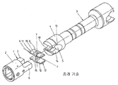
종래 기술은 도 1 및 도 2에 도시되어 있다. 도 1에는 관절 스핀들(3)과의 연결을 위해 설부(1)를 구비하여 형성된 커플링 슬리브(2)가 분해도로 도시되어 있다.The prior art is shown in FIGS. 1 and 2. 1 shows an exploded view of a
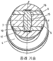
도 2에는 도 1의 커플링 슬리브가 절단선 II-II에 따라 절단되어 수직 단면도로 도시되어 있다.In Fig. 2 the coupling sleeve of Fig. 1 is cut along the cutting line II-II and shown in vertical section.
관절 스핀들(3)은 설부(1)를 수용하기 위한 리세스(5)를 구비하여 형성된 관절 헤드(4)를 포함한다. 설부(1)는 커플링 슬리브(1)의 외측면으로 향해 있는 원통형 윤곽부와 커플링 슬리브(1)의 내측면으로 향해 있는 장방형 윤곽부를 구비하여 손가락 모양의 평판(flat sheet)을 형성하는 2개의 돌출 부재(6, 7)로 구성된다. 상기 부재(6, 7)들 상에는 2개의 슬라이딩 플레이트(9, 10)를 구비한 슬라이딩 블록(8)이 고정된다. 슬라이딩 플레이트(9, 10)들은 리세스(5) 내에 안착하는 원통형 표면(11, 12)들을 포함하여, 이들 원통형 표면은, 슬라이딩 블록(8)과 관절 스핀들이 관절 스핀들(3)의 종축(x)에 대해 수직으로 축(z)을 중심으로 회전 또는 회동 가능하게 한다. 상기 표면(11, 12)들은 관절 스핀들(3)의 관절 헤드(4) 내 리세스(5)의 내부에서 대응하는 윤곽부(13, 14)들 내로 삽입 장착되도록 형성된다.The articulation spindle (3) comprises an articulation head (4) formed with a recess (5) for receiving a tongue (1). The tongue 1 has a cylindrical contour directed towards the outer side of the coupling sleeve 1 and a rectangular contour directed towards the inner side of the coupling sleeve 1 to form a flat sheet of finger shape. Two protruding
관절 블록 또는 슬라이드 플레이트(9, 10)들은, 부재(6, 7)들에 의해 형성되는 커플링 슬리브 리세스 내로 돌출되면서 일반적으로 슬라이딩 블록(9 또는 10)들 내의 보어부(16 또는 17) 내에서 안내되는 볼트(15)에 의해 서로 결합된다. 관절 헤드(4)와 커플링 슬리브(2) 사이의 상대 운동은 슬라이딩 블록(8)의 회전에 의해, 그리고 부재(6, 7)들의 회동 운동에 의해 실행된다. 슬라이딩 플레이트(9, 10)들은 y 축의 방향으로 슬라이딩 플레이트(9, 10)들의 미끄러짐을 방지하기 위해 정지부에 의해 안내되어야 한다. 이를 위해 표준으로서 관절 헤드(4)의 중심부에 원통형 그루브(18)가 제공되며, 그에 따라 슬라이딩 플레이트(9, 10)들이 구비된 가이드 캠(19)으로 상기 원통형 그루브 내로 삽입된다.The articulating block or
그러나 과거 확인된 점에 따르면, 압연 시스템의 출력 상승에 의해 상기 가이드 그루브들에서 응력 균열이 발생하였다.However, in the past, stress cracking occurred in the guide grooves due to the power increase of the rolling system.
본 발명의 목적은, 최초에 언급한 유형의 관절 스핀들에 있어서, 토크의 전달 시에 자체의 출력 용량이 상승하도록 상기 관절 스핀들을 개량하는 것에 있다.It is an object of the present invention to improve the articulating spindle such that its output capacity rises upon transmission of torque in the articulating spindle of the first mentioned type.
상기 목적은 최초에 언급한 관절 스핀들에서 본 발명에 따라 회전체 윤곽부들이 오목하거나 볼록하게 형성되고 리세스도 그에 상응하게 볼록하거나 오목하게 형성됨으로써 달성된다.This object is achieved by the concave or convex formation of the rotor contours and the recesses correspondingly convex or concave in accordance with the invention in the initially mentioned articulated spindle.
본 발명에 의해서는 응력 균열의 발생이 방지되면서도, 모따기, 반경부의 연마 또는 반경부의 경화와 같은 특별한 조치를 강구하지 않아도 된다. 본 발명에 의해서는 관절 헤드 내 응력 레벨 감소를 위한 기본적인 해결 방법이 제공되면서도, 요구되는 가이드 특성은 소실되지 않는다. 가이드 그루브 대신에 2 방향으로 y축에 대해 대칭을 이루는 방식으로 연장되는 균일한 공 모양 윤곽부가 이용되며, 이 윤곽부는 슬라이딩 플레이트 횡축 전체에, 즉 y 축에 중첩된다.According to the present invention, while the occurrence of stress cracking is prevented, no special measures such as chamfering, polishing of the radius part or curing of the radius part need be taken. While the present invention provides a basic solution for reducing stress levels in the articulation head, the required guide characteristics are not lost. Instead of the guide grooves a uniform ball-shaped contour is used which extends in a symmetrical manner with respect to the y axis in two directions, which contour overlaps the entire sliding plate transverse axis, ie on the y axis.
본 발명의 바람직한 개선예들은 종속항, 명세서 및 도면으로부터 제시된다.Advantageous refinements of the invention are presented from the dependent claims, the specification and the drawings.
바람직하게는 특히 회전체 윤곽부들이 부분 영역에서 통(barrel)의 형태 또는 한 잎 쌍곡면(hyperboloid of one sheet)의 형태를 보유한다.Preferably the rotor contours in particular retain the form of a barrel or of a hyperboloid of one sheet in the partial region.
통 형태는 구면, 타원형 또는 포물형 곡률을 갖는 곡선의 선삭(turning)을 통해 제조된다. 곡률에 의해 곡선의 형상은 슬라이딩 블록의 필요한 횡방향 안내 시 최적의 응력 상태에 부합하게 형성될 수 있다. 특별한 경우는 원호 섹션을 형성하는 통의 곡선이다. 이와 관련하여 각각의 실시예에 따라 관절부의 유격(play)은 감소되거나 확대될 수 있다.The barrel shape is produced by turning of a curve having a spherical, elliptical or parabolic curvature. The curvature allows the shape of the curve to be formed in accordance with the optimum stress state in the required lateral guiding of the sliding block. A special case is the curve of the barrel forming the arc section. In this regard, the play of the joint part may be reduced or enlarged according to each embodiment.
또한, 바람직하게는 슬라이딩 블록은 슬라이딩 블록 자체를 수용하는 리세스와 관련하여 응력을 받는 상태로 존재한다.In addition, the sliding block is preferably in a stressed state with respect to the recess for receiving the sliding block itself.
바람직하게는 관절 헤드의 영역에서 관절 스핀들은, 응력이 일측의 슬라이딩 블록의 회전체 윤곽부들과 타측의 리세스의 상호 간 비례하는 형태에 의해 결정되도록 구성된다.Preferably the articulation spindle in the region of the articulation head is configured such that the stress is determined by the form of proportionality between the rotor contours of the sliding block on one side and the recess on the other side.
관절 스핀들은 특히 바람직한 실시예에 따라 슬라이딩 블록의 응력이 두 슬라이딩 몸체의 상호 간 이격 간격을 조정하는 조정 수단에 의해, 특히 조정 볼트에 의해 리세스에 대향하여 조정되는 것을 특징으로 한다.The articulating spindle is according to a particularly preferred embodiment characterized in that the stress of the sliding block is adjusted against the recess by adjusting means for adjusting the mutually spaced spacing of the two sliding bodies, in particular by means of adjusting bolts.
또한, 본 발명은 앞서 상세하게 설명한 것처럼 관절 스핀들 내에서 이용하기 위한 슬라이딩 블록에도 관한 것이다.The invention also relates to a sliding block for use in the articulating spindle as described in detail above.
도 1은 관절 스핀들(3)과의 연결을 위해 설부(1)를 구비하여 형성된 종래 기술의 커플링 슬리브(2)의 분해도이다.
도 2는 도 1의 커플링 슬리브가 절단선 II-II에 따라 도시된 수직 단면도이다.
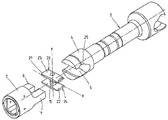
도 3은 통 형태로 형성되는 슬라이딩 블록들을 포함하는 본 발명에 따른 관절 스핀들을 도시한 분해 사시도이다.
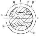
도 4는 도 3의 관절 스핀들을 절단선 IV-IV에 따라 절단하여 도시한 수직 단면도이다.
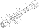
도 5는 한 잎 쌍곡면 형태의 슬라이딩 블록들을 포함하는 본 발명에 따른 관절 스핀들을 도시한 분해 사시도이다.
도 6은 도 5의 관절 스핀들을 절단선 V-V에 따라 절단하여 도시한 수직 단면도이다.1 is an exploded view of a
FIG. 2 is a vertical sectional view of the coupling sleeve of FIG. 1 taken along cut line II-II. FIG.
3 is an exploded perspective view showing the articulation spindle according to the present invention including the sliding blocks formed in a cylindrical shape.
4 is a vertical cross-sectional view taken along the cutting line IV-IV of the articulation spindle of FIG. 3.
5 is an exploded perspective view showing the articulation spindle according to the present invention including sliding blocks in the form of a leaf hyperboloid.
FIG. 6 is a vertical cross-sectional view of the joint spindle of FIG. 5 taken along a cutting line VV.
아래에서 본 발명은 2가지 실시예에 따라 더욱 상세하게 설명된다.In the following the invention is explained in more detail according to two embodiments.
2개의 핑거(6, 7)를 포함하는 커플링 슬리브(2)(도 3 및 4)는 종래 기술(도 1 및 2 참조)로부터 공지된 방식으로 스핀들(3)의 관절 헤드(4)와 상호 작용한다. 종래 기술과 다르게 슬라이딩 블록(20)은 2개의 슬라이딩 플레이트(21, 22)를 장착하고 있으며, 이들 슬라이딩 플레이트 각각 통형 표면(23, 24)을 포함한다. 또한, 종래 기술로부터 공지된 것처럼, 두 슬라이딩 플레이트(21, 22)는 볼트(15)에 의해 서로 결합된다. 종래 기술과 다르게 스핀들(3)의 관절 헤드(4)의 리세스(5) 내에는 가이드 그루브(18)가 요구되지 않으며, 마찬가지로 가이드 캠(19)도 필요하지 않다.The coupling sleeve 2 (FIGS. 3 and 4) comprising two
오히려 리세스가 볼록한 표면(23, 24)에 정확히 부합하게 형성되고 적어도 실질적으로 표면(23, 24)들과 동일한 곡률을 갖는 오목한 윤곽부(25)를 보유하는 것만으로 충분하고 그처럼 형성되기만 하면 된다.Rather, it is sufficient and sufficient for the recess to have a
본 발명의 추가의 실시예(도 5 및 6)에 따라 슬라이딩 블록(26)은 각각 한 잎 쌍곡면의 부채꼴로서 형성되는 표면(29, 30)을 구비하여 형성되는 2개의 슬라이딩 플레이트(27, 28)를 포함한다. 또한, 이런 경우에도 두 슬라이딩 플레이트(27, 28)는 볼트(15)에 의해 서로 결합된다. 제1 실시예의 경우에서처럼 스핀들(3)의 관절 헤드(4)의 리세스(5) 내에는 가이드 그루브(18)는 요구되지 않으며, 마찬가지로 가이드 캠(19)도 필요하지 않다.According to a further embodiment of the invention (FIGS. 5 and 6) the sliding
오히려 본 실시예에서도 리세스가 오목한 표면(29, 30)에 정확히 부합하게 형성되고 적어도 실질적으로 표면(29, 30)과 동일한 곡률을 갖는 볼록한 윤곽부(31)를 보유하는 것만으로 충분하고 그처럼 형성되기만 하면 된다.Rather, in this embodiment, it is sufficient and only sufficient to have the
본 발명에 의해 제공되는 슬라이딩 블록(20, 26)들의 구성에 따라, 표면(23, 24) 또는 표면(29, 30)의 형태에 의해서는, 슬라이딩 블록(20, 26)들이 스스로 중심 결정되면서 윤곽부(25, 31) 내에 장착되고, 그와 동시에 종래 기술에서 요구되는 것과 같은 가이드 캠 및 가이드 그루브는 생략될 수 있게 된다.According to the configuration of the sliding
1: 설부
2: 커플링 슬리브
3: 관절 스핀들
4: 관절 헤드
5: 리세스
6: 부재
7: 부재
8: 슬라이딩 블록
9: 슬라이딩 플레이트
10: 슬라이딩 플레이트
11: 원통형 표면
12: 원통형 표면
13: 윤곽부(contour)
14: 윤곽부
16: 보어부(bore)
17: 보어부
18: 그루브(groove)
19: 가이드 캠(guide cam)
20: 슬라이딩 블록
21: 슬라이딩 플레이트
22: 슬라이딩 플레이트
23: 표면
24: 표면
25: 윤곽부
26: 슬라이딩 블록
27: 슬라이딩 플레이트
28: 슬라이딩 플레이트
29: 표면
30: 표면
31: 윤곽부1: tongue
2: coupling sleeve
3: articulated spindle
4: articulated head
5: recess
6: absence
7: absence
8: sliding block
9: sliding plate
10: sliding plate
11: cylindrical surface
12: cylindrical surface
13: contour
14: contour
16: bore
17: Bore Fisher
18: groove
19: guide cam
20: sliding block
21: sliding plate
22: sliding plate
23: surface
24: surface
25: contour
26: sliding block
27: sliding plate
28: sliding plate
29: surface
30: surface
31: contour
Claims (7)
상기 회전체 윤곽부(23, 24; 29, 30)들은 오목하거나 볼록하게 형성되며, 상기 리세스(25, 31)는 그에 상응하게 볼록하거나 오목하게 형성되는 것을 특징으로 하는 관절 스핀들(3).As articulation spindle 3, comprising a coupling sleeve to form a connection with the articulation head, or including the articulation head 4 to form a connection with the coupling sleeve 2, in particular in the drive mechanism of the rolling mill. The tongue of the coupling sleeve 2 engages into the cylindrical opening 5 of the articulation head 4 located transversely to the axis of rotation and between the articulation head and the tongue 1 a sliding block 19. , 26 are arranged, the sliding block being formed by two sliding bodies 21, 22; 27, 28 comprising rotor contours 23, 24; 29, 30 in the partial region; The body is rotatable in the rotatable recesses 25, 31 formed in conformity with the shape of the sliding bodies 21, 22; 27, 28 in the joints so as to carry out the rotational movement in the articulation head 4. Disposed on the articulation spindle 3 In
The rotating body contours (23, 24; 29, 30) are concave or convex, and the recesses (25, 31) are correspondingly convex or concave.
Applications Claiming Priority (2)
| Application Number | Priority Date | Filing Date | Title |
|---|---|---|---|
| DE102009053129A DE102009053129A1 (en) | 2009-11-13 | 2009-11-13 | Sliding block for a joint spindle |
| DE102009053129.7 | 2009-11-13 |
Publications (1)
| Publication Number | Publication Date |
|---|---|
| KR20120073315A true KR20120073315A (en) | 2012-07-04 |
Family
ID=43379020
Family Applications (1)
| Application Number | Title | Priority Date | Filing Date |
|---|---|---|---|
| KR1020127011124A KR20120073315A (en) | 2009-11-13 | 2010-11-12 | Sliding block for an articulated spindle |
Country Status (10)
| Country | Link |
|---|---|
| US (1) | US9228615B2 (en) |
| EP (1) | EP2499389B1 (en) |
| JP (1) | JP5654032B2 (en) |
| KR (1) | KR20120073315A (en) |
| CN (1) | CN102597560B (en) |
| DE (1) | DE102009053129A1 (en) |
| ES (1) | ES2664949T3 (en) |
| RU (1) | RU2532207C2 (en) |
| TW (1) | TWI391579B (en) |
| WO (1) | WO2011058133A1 (en) |
Families Citing this family (7)
| Publication number | Priority date | Publication date | Assignee | Title |
|---|---|---|---|---|
| ITMI20130287A1 (en) * | 2013-02-27 | 2014-08-28 | Danieli Off Mecc | ELASTIC JOINT FOR PUNCHES |
| KR20170005445A (en) * | 2014-05-05 | 2017-01-13 | 로오드 코포레이션 | Mud motor transmission |
| TW201605586A (en) * | 2014-08-14 | 2016-02-16 | Honiton Ind Inc | Universal structure |
| TW201605585A (en) * | 2014-08-14 | 2016-02-16 | Honiton Ind Inc | Universal structure |
| CN109731927A (en) * | 2019-01-23 | 2019-05-10 | 合肥市百胜科技发展股份有限公司 | A kind of guide and guards |
| DE102020102081A1 (en) * | 2020-01-29 | 2021-07-29 | Vat Holding Ag | Connection device for connecting a valve rod to a closure member of a vacuum valve |
| CN112648298A (en) * | 2020-12-28 | 2021-04-13 | 奇瑞汽车股份有限公司 | Vehicle transmission |
Family Cites Families (31)
| Publication number | Priority date | Publication date | Assignee | Title |
|---|---|---|---|---|
| US1231249A (en) * | 1915-03-17 | 1917-06-26 | United Eng Foundry Co | Flexible shaft-coupling. |
| US1413848A (en) | 1921-05-19 | 1922-04-25 | Int Motor Co | Universal joint |
| US1532752A (en) * | 1924-09-12 | 1925-04-07 | United Eng Foundry Co | Rolling-mill-spindle coupling |
| GB262144A (en) * | 1925-11-30 | 1927-03-31 | Skf Svenska Kullagerfab Ab | Improvements in or relating to couplings for use in rolling mills or the like |
| FR624874A (en) * | 1925-11-30 | 1927-07-28 | Skf Svenska Kullagerfab Ab | Improvements to coupling boxes for rolling mills |
| GB284462A (en) | 1927-01-21 | 1928-02-02 | John Meredith Rubury | Improvements in and relating to universal joints and couplings |
| US2153093A (en) * | 1936-10-17 | 1939-04-04 | American Steel & Wire Co | Universal coupling |
| US2260567A (en) * | 1940-05-25 | 1941-10-28 | Thomas L Gatke | Molded composition slipper bearing |
| US2305699A (en) * | 1941-09-29 | 1942-12-22 | American Brake Shoe & Foundry | Universal coupling |
| US2361629A (en) | 1942-02-28 | 1944-10-31 | American Brake Shoe Co | Bearing |
| US2460361A (en) | 1943-09-22 | 1949-02-01 | Continental Diamond Fibre Co | Slipper bearing |
| US2895314A (en) * | 1958-07-25 | 1959-07-21 | Tony W Helm | Universal joint |
| US3070978A (en) * | 1960-07-20 | 1963-01-01 | Ilseder Huette | Coupling joint |
| BE608951A (en) | 1960-10-12 | 1962-02-01 | Ferroplast | Subdivided articulation fur for articulated shafts, in particular those of rolling mill stands. |
| US3469416A (en) * | 1967-01-16 | 1969-09-30 | Peter J Snyder | Universal spindle coupling and the like |
| US3713791A (en) * | 1969-01-17 | 1973-01-30 | G Oakes | Slipper bearing |
| DE2251919A1 (en) * | 1972-10-23 | 1974-04-25 | Rolf Herrmann | LOW-WEAR AND BACKLASH-FREE JOINT STONES |
| SE409751B (en) * | 1976-07-06 | 1979-09-03 | Morgaardshammar Ab | SLIDING BLOCK COUPLING |
| SU593020A1 (en) * | 1976-08-06 | 1978-02-15 | Пермский Филиал Всесоюзного Ордена Трудового Красного Знамени Научно-Исследовательского Института Буровой Техники | Articulated coupling |
| DE2656257A1 (en) | 1976-12-11 | 1978-06-15 | Wuppermann Gmbh Theodor | Bearing blocks for use between articulated spindles and couplings - esp. for driving rolling mills; allowing easy replacement of blocks |
| JPS5836405Y2 (en) * | 1979-04-20 | 1983-08-16 | 新日本製鐵株式会社 | Rolling mill spindle universal joint |
| JPS55154601A (en) | 1979-05-21 | 1980-12-02 | Nissan Motor Co Ltd | Electronic control unit for internal combustion engine |
| DE3000477A1 (en) * | 1980-01-08 | 1981-07-09 | Lorenz 7312 Kirchheim Baron | Universal shaft joint for pump - has two pivot pins turning in coupling head and shaft end at right angles |
| JPS6026807B2 (en) | 1981-03-18 | 1985-06-26 | 新日本製鐵株式会社 | Processing method for continuously cast austenitic stainless steel slabs |
| JPS57155322U (en) * | 1981-03-26 | 1982-09-29 | ||
| JPS60123432U (en) * | 1984-01-27 | 1985-08-20 | 山陽特殊製鋼株式会社 | universal cutlet spring |
| US5288271A (en) * | 1992-04-13 | 1994-02-22 | Houston Engineers, Inc. | Constant velocity universal joint assembly for downhole motor |
| US5496219A (en) * | 1993-10-19 | 1996-03-05 | The Anspach Effort, Inc. | Universal joint with dual rollers |
| DE10306542B3 (en) | 2003-02-13 | 2004-06-24 | Sms Demag Ag | Sliding pad for articulated spindles for the drives of rolling mills comprises a metallic inner body and an outer layer made from polymer fiber material surrounding the inner body |
| CA2472642C (en) * | 2004-06-07 | 2009-05-26 | William R. Wenzel | Drive line for down hole mud motor |
| WO2009132414A1 (en) * | 2008-04-30 | 2009-11-05 | Dreco Energy Services Ltd. | Drive shaft assembly for a downhole motor |
-
2009
- 2009-11-13 DE DE102009053129A patent/DE102009053129A1/en not_active Withdrawn
-
2010
- 2010-11-12 ES ES10779308.5T patent/ES2664949T3/en active Active
- 2010-11-12 EP EP10779308.5A patent/EP2499389B1/en active Active
- 2010-11-12 RU RU2012124048/11A patent/RU2532207C2/en not_active IP Right Cessation
- 2010-11-12 JP JP2012538342A patent/JP5654032B2/en active Active
- 2010-11-12 US US13/509,731 patent/US9228615B2/en active Active
- 2010-11-12 CN CN201080051285.1A patent/CN102597560B/en active Active
- 2010-11-12 WO PCT/EP2010/067373 patent/WO2011058133A1/en active Application Filing
- 2010-11-12 KR KR1020127011124A patent/KR20120073315A/en not_active Application Discontinuation
- 2010-11-12 TW TW099138906A patent/TWI391579B/en not_active IP Right Cessation
Also Published As
| Publication number | Publication date |
|---|---|
| ES2664949T3 (en) | 2018-04-24 |
| DE102009053129A1 (en) | 2011-05-19 |
| TWI391579B (en) | 2013-04-01 |
| JP2013510721A (en) | 2013-03-28 |
| EP2499389B1 (en) | 2018-01-10 |
| RU2012124048A (en) | 2013-12-20 |
| US20120244954A1 (en) | 2012-09-27 |
| EP2499389A1 (en) | 2012-09-19 |
| TW201121672A (en) | 2011-07-01 |
| CN102597560A (en) | 2012-07-18 |
| WO2011058133A1 (en) | 2011-05-19 |
| JP5654032B2 (en) | 2015-01-14 |
| CN102597560B (en) | 2015-08-19 |
| US9228615B2 (en) | 2016-01-05 |
| RU2532207C2 (en) | 2014-10-27 |
Similar Documents
| Publication | Publication Date | Title |
|---|---|---|
| KR20120073315A (en) | Sliding block for an articulated spindle | |
| DE60110751T2 (en) | Tilting pad STORAGE DEVICE | |
| JP2013510721A5 (en) | ||
| WO2011036969A1 (en) | Linear actuator | |
| GB2056620A (en) | Shaft couplings | |
| US6379046B1 (en) | Modular support structure for hydrodynamic bearing | |
| US8789401B2 (en) | Method for producing a support roll for a rolling mill | |
| US9714682B2 (en) | Joint yoke for a universal joint and universal joint | |
| GB2210952A (en) | A device for transferring load through a rolling element mounted with a plain bearing, methods for producing the device and a transmission joint provided with the latter | |
| CN102348515A (en) | A roller comprising a drive shaft and a roller ring, as well as a method for assembling such a roller | |
| US9175731B2 (en) | Constant velocity joint | |
| RU2569071C1 (en) | Shaft with ball-and-socket joint | |
| US3469416A (en) | Universal spindle coupling and the like | |
| CN105257748B (en) | Spring element and the safety clutch using the spring element | |
| CN101657276B (en) | Rolling mill and roll thereof | |
| CN207357973U (en) | A kind of plate punch press altogether | |
| JP2017202511A (en) | Spindle coupling, joint for spindle coupling and rolling roll driving device | |
| DE3143062C2 (en) | Ball joint | |
| CN210686490U (en) | Hydraulic oil cylinder with bolt locking device | |
| DE102005006816A1 (en) | Roll to compensate for bends in sheet material has bearing housing coupled to yoke by twin-arm suspension support | |
| US1135510A (en) | Universal coupling for shafts. | |
| CN201214576Y (en) | Guiding power transmission structure of coiler spindle | |
| RU1780892C (en) | Multipurpose spindle pivot joint | |
| US2305700A (en) | Universal coupling | |
| DE2751151B2 (en) | Elastic shaft coupling |
Legal Events
| Date | Code | Title | Description |
|---|---|---|---|
| A201 | Request for examination | ||
| E902 | Notification of reason for refusal | ||
| E601 | Decision to refuse application |