KR20120068197A - Cylinder apparatus for up/down balancing cross-rail of machine tool - Google Patents
Cylinder apparatus for up/down balancing cross-rail of machine tool Download PDFInfo
- Publication number
- KR20120068197A KR20120068197A KR1020100129705A KR20100129705A KR20120068197A KR 20120068197 A KR20120068197 A KR 20120068197A KR 1020100129705 A KR1020100129705 A KR 1020100129705A KR 20100129705 A KR20100129705 A KR 20100129705A KR 20120068197 A KR20120068197 A KR 20120068197A
- Authority
- KR
- South Korea
- Prior art keywords
- hydraulic cylinder
- leveling
- cross rail
- machine tool
- cylinder device
- Prior art date
Links
- 238000009434 installation Methods 0.000 claims abstract description 19
- NJPPVKZQTLUDBO-UHFFFAOYSA-N novaluron Chemical compound C1=C(Cl)C(OC(F)(F)C(OC(F)(F)F)F)=CC=C1NC(=O)NC(=O)C1=C(F)C=CC=C1F NJPPVKZQTLUDBO-UHFFFAOYSA-N 0.000 claims description 22
- 238000000034 method Methods 0.000 claims 2
- 244000145845 chattering Species 0.000 abstract 1
- 238000003754 machining Methods 0.000 description 7
- 239000000463 material Substances 0.000 description 6
- 238000010586 diagram Methods 0.000 description 4
- 238000012986 modification Methods 0.000 description 2
- 230000004048 modification Effects 0.000 description 2
- 238000010276 construction Methods 0.000 description 1
- 239000004570 mortar (masonry) Substances 0.000 description 1
Images


Classifications
-
- B—PERFORMING OPERATIONS; TRANSPORTING
- B23—MACHINE TOOLS; METAL-WORKING NOT OTHERWISE PROVIDED FOR
- B23Q—DETAILS, COMPONENTS, OR ACCESSORIES FOR MACHINE TOOLS, e.g. ARRANGEMENTS FOR COPYING OR CONTROLLING; MACHINE TOOLS IN GENERAL CHARACTERISED BY THE CONSTRUCTION OF PARTICULAR DETAILS OR COMPONENTS; COMBINATIONS OR ASSOCIATIONS OF METAL-WORKING MACHINES, NOT DIRECTED TO A PARTICULAR RESULT
- B23Q1/00—Members which are comprised in the general build-up of a form of machine, particularly relatively large fixed members
- B23Q1/25—Movable or adjustable work or tool supports
- B23Q1/26—Movable or adjustable work or tool supports characterised by constructional features relating to the co-operation of relatively movable members; Means for preventing relative movement of such members
- B23Q1/34—Relative movement obtained by use of deformable elements, e.g. piezoelectric, magnetostrictive, elastic or thermally-dilatable elements
-
- B—PERFORMING OPERATIONS; TRANSPORTING
- B23—MACHINE TOOLS; METAL-WORKING NOT OTHERWISE PROVIDED FOR
- B23Q—DETAILS, COMPONENTS, OR ACCESSORIES FOR MACHINE TOOLS, e.g. ARRANGEMENTS FOR COPYING OR CONTROLLING; MACHINE TOOLS IN GENERAL CHARACTERISED BY THE CONSTRUCTION OF PARTICULAR DETAILS OR COMPONENTS; COMBINATIONS OR ASSOCIATIONS OF METAL-WORKING MACHINES, NOT DIRECTED TO A PARTICULAR RESULT
- B23Q1/00—Members which are comprised in the general build-up of a form of machine, particularly relatively large fixed members
- B23Q1/01—Frames, beds, pillars or like members; Arrangement of ways
-
- B—PERFORMING OPERATIONS; TRANSPORTING
- B23—MACHINE TOOLS; METAL-WORKING NOT OTHERWISE PROVIDED FOR
- B23Q—DETAILS, COMPONENTS, OR ACCESSORIES FOR MACHINE TOOLS, e.g. ARRANGEMENTS FOR COPYING OR CONTROLLING; MACHINE TOOLS IN GENERAL CHARACTERISED BY THE CONSTRUCTION OF PARTICULAR DETAILS OR COMPONENTS; COMBINATIONS OR ASSOCIATIONS OF METAL-WORKING MACHINES, NOT DIRECTED TO A PARTICULAR RESULT
- B23Q1/00—Members which are comprised in the general build-up of a form of machine, particularly relatively large fixed members
- B23Q1/25—Movable or adjustable work or tool supports
- B23Q1/26—Movable or adjustable work or tool supports characterised by constructional features relating to the co-operation of relatively movable members; Means for preventing relative movement of such members
- B23Q1/38—Movable or adjustable work or tool supports characterised by constructional features relating to the co-operation of relatively movable members; Means for preventing relative movement of such members using fluid bearings or fluid cushion supports
Abstract
Description
본 발명은, 공작기계의 크로스 레일에 적용되는 유압 실린더 장치에 관한 것으로, 특히, 상하 밸런싱 구조가 개선된 공작기계용 크로스 레일의 상하 밸런스를 위한 유압 실린더 장치에 관한 것이다.
BACKGROUND OF THE INVENTION 1. Field of the Invention The present invention relates to a hydraulic cylinder device applied to a cross rail of a machine tool, and more particularly to a hydraulic cylinder device for vertical balance of a cross rail for a machine tool with improved up and down balancing structure.
공작기계에는 터닝센터, 머시닝센터, NC보링, 문형머시닝센터, 스위스 턴, 방전 가공기 등을 비롯하여 다양한 종류가 작업의 용도에 맞게 널리 사용되고 있다.Various types of machine tools are widely used for the purpose of work, including turning centers, machining centers, NC boring, door machining centers, swiss turns, and electric discharge machines.
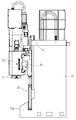
이러한 공작기계들 중에서도 그 크기가 대형일 뿐만 아니라 크로스 레일(16)이 상하 방향, 즉 W축 방향으로 이송될 수 있는 공작기계에 대해 도 1을 참조하여 간략하게 설명하면 다음과 같다.Among these machine tools, a machine tool capable of being not only large but also having a
도 1은 종래 기술에 따른 공작기계용 크로스 레일에 적용되는 유압 실린더 장치의 구조도이다.1 is a structural diagram of a hydraulic cylinder device applied to a cross rail for a machine tool according to the prior art.
이 도면에 도시된 공작기계는 크로스 레일(16)이 이송모터(15)에 의해 상하 방향인 W축 방향으로 이송될 수 있는 구조를 가진 대형 공작기계이다.The machine tool shown in this figure is a large machine tool having a structure in which the
크로스 레일(16)의 주변에는 크로스 레일(16)과 함께 W축 방향으로 이송되는 램 유닛(17)과 새들 유닛(18)이 구비된다.The periphery of the
참고로, 대형 공작기계는 도시된 크로스 레일(16)이 고정된 형태와 크로스 레일(16)이 W축인 상하 방향으로 이송되는 도 1과 같은 형태로 나뉜다.For reference, a large machine tool is divided into a form in which the
도시하지 않았지만 크로스 레일(16)이 고정된 형태의 대형 공작기계는, 특히 높이가 낮은 공작물을 가공할 때 램 유닛(17)이 Z축 방향으로 많은 거리를 이송할 수밖에 없어 그 돌출 길이가 마치 긴 외팔보 형태가 되기 때문에 가공 작업 시 떨림 현상 등이 발생될 수 있다.Although not shown, a large machine tool having a fixed
이에 비해, 크로스 레일(16)이 W축 상하 방향으로 이송될 수 있는 도 1의 대형 공작기계는, 크로스 레일(16)이 먼저 하방으로 이송된 후에 램 유닛(17)이 이송되는 구조를 가지기 때문에 램 유닛(17)이 돌출 길이가 아주 작아 가공 작업 시 떨림 현상 없이 안정적일 수 있다.In contrast, the large machine tool of FIG. 1 in which the
한편, 도 1에 도시된 대형 공작기계는 크로스 레일(16)과 램 유닛(17), 그리고 새들 유닛(18) 모두가 W축 방향으로 이송되고 있는데, 이 경우 이들의 중량이 수십 톤에 달하기 때문에 이들의 동작을 이송모터(15) 혼자 담당하기에는 한계가 따른다.On the other hand, in the large machine tool shown in FIG. 1, the
따라서 보통은 도 1처럼 유압 실린더 장치(20)가 부가되어 W축 방향의 이송을 보조하게 된다.Therefore, the
도 1은 측면도이기 때문에 유압 실린더 장치(20)가 한 개 도시되어 있지만, 정면에서 바라보면 유압 실린더 장치(20)는 좌우 한 쌍의 컬럼(12) 영역에 하나씩 적용되는 것이 일반적이다. 이때, 유압 실린더 장치(20)는 컬럼(12)의 상부에 설치되거나 아니면 도 1처럼 크로스 레일(16)의 하부에 설치된다.1 is a side view, so one
하지만, 유압 실린더 장치(20)를 상기와 같이 단순히 적용하는 경우, 다음과 같은 문제점이 있다.However, when simply applying the
도시하지는 않았지만, 유압 실린더 장치(20)가 컬럼(12)의 상부에 설치되는 경우는 공작기계의 전체 높이가 높아질 수밖에 없을 뿐만 아니라 유압 실린더 장치(20)의 직경이 커지는 등의 문제점이 있다.Although not shown, when the
이에 비해, 유압 실린더 장치(20)가 크로스 레일(16)의 하부에 설치되는 경우는 도 1처럼 유압 실린더 장치(20)의 하단부 영역을 컬럼(12)의 돌출된 전방부(12a)에 파묻는 형태로 가공 및 설치해야 하기 때문에, 컬럼(12)의 소재비 및 가공비 등의 원가 상승이 유발되는 문제점이 있다.In contrast, when the
특히 유압 실린더 장치(20)가 크로스 레일(16)의 하부에 설치되는 경우는, 유압 실린더 장치(20)가 상하, 좌우, 전후 등의 각 방향으로 조절될 수 없기 때문에, 컬럼(12), 유압 실린더 장치(20) 및 크로스 레일(16) 간의 상대적인 위치 조정, 즉 상대적인 얼라인(align) 작업이 컬럼(12)과 크로스 레일(16) 등 대형 부품의 가공에만 의존될 수밖에 없다. 때문에, 결과적으로 크로스 레일(16)의 정도 작업을 수행하기가 어려워 크로스 레일(16)의 상하 밸런스를 맞추기가 용이하지 않은 문제점이 있다.In particular, when the
이에, 본 발명은 전술한 바와 같은 문제점들을 해소하기 위해 안출된 것으로, 그 목적은 불필요하게 컬럼의 사이즈를 거대하게 유지하거나 혹은 종래처럼 컬럼을 다시 파내어 작업하는 등의 소재비 및 가공비 상승 문제를 적절하게 해소할 수 있으며, 무엇보다도 간단하고도 단순한 구조로서 W축 발란스 정도 조정 작업을 간편하게 수행할 수 있어 크로스 레일의 상하 밸런스를 용이하게 맞출 수 있는 공작기계용 크로스 레일의 상하 밸런스를 위한 유압 실린더 장치를 제공하는 것이다.
Accordingly, the present invention has been made to solve the above problems, the object of the present invention is to adequately solve the problem of material cost and processing cost increase, such as unnecessarily maintaining the size of the column unnecessarily or digging out the column again. Hydraulic cylinder device for vertical balance of cross rail for machine tool that can easily adjust the balance of the W-axis balance by easily adjusting the W-axis balance by the simple and simple structure. To provide.
전술한 목적을 달성하기 위해, 본 발명은 실린더 본체(131)와, 상기 실린더 본체(131)에 대해 길이 연장 또는 축소되는 실린더 로드(132)를 구비하며, 상기 실린더 로드(132)의 단부가 공작기계의 크로스 레일(cross-rail, 116)에 결합되는 유압 실린더(130); 및 하단부는 상기 공작기계와는 이격된 위치에서 상기 공작기계가 설치되는 설치면에 고정되고 상단부는 상기 실린더 본체(131)를 지지하며, 상기 크로스 레일(116)의 상하 밸런스를 위하여 상기 설치면에 대해 상기 유압 실린더(130)를 상기 설치면 상의 X축 또는 Y축 방향으로 위치 이동시키는 레벨링 유닛(140);을 포함하고, 상기 레벨링 유닛(140)은, 상기 설치면에 고정되며, 상면의 둘레 방향을 따라 다수의 브래킷(151a~151d)이 구비되는 레벨링 받침대(150); 상기 다수의 브래킷(151a~151d) 사이에서 상기 레벨링 받침대(150)의 상부에 위치되고 상기 유압 실린더(130)와 연결되는 레벨링 블록(160); 및 상기 다수의 브래킷(151a~151d)에 각각 전진 또는 후퇴 가능하게 결합되되 해당 위치에서 상기 레벨링 블록(160)을 선택적으로 가압하는 다수의 가압부재(170a~170d)를 포함하는 공작기계용 크로스 레일의 상하 밸런스를 위한 유압 실린더 장치를 제공한다.In order to achieve the above object, the present invention includes a
또한 본 발명은 위의 본 발명의 일실시예에 대하여 다음의 구체적인 실시예들을 더 제공한다.In addition, the present invention further provides the following specific embodiments of the above-described embodiment of the present invention.
본 발명의 일 실시예에 따르면, 상기 레벨링 받침대(150)의 판면에는 상기 레벨링 받침대(150)를 상기 설치면에 고정시키기 위한 앵커(154)가 통과되는 다수의 통공(152)이 더 형성되며, 상기 다수의 통공(152)은 상기 레벨링 받침대(150)의 판면에서 적어도 삼각 구도로 배치되는 것을 특징으로 한다.According to one embodiment of the present invention, the plate surface of the leveling
본 발명의 일 실시예에 따르면, 상기 레벨링 블록(160)은, 내부에 가압핀(162)에 의해 이동될 수 있는 이동편(163): 및 상단에는 상기 실린더 본체(131)의 하단부에 형성되는 샤프트(131a)가 조립되어 이동이 저지되는 볼 와셔(161)를 더 구비하며, 상기 이동편(163)은 레벨링 블록(160) 내에서 쐐기 형태로 마련되는 것을 특징으로 한다.
According to one embodiment of the invention, the
본 발명에 따르면, 불필요하게 컬럼의 사이즈를 거대하게 유지하거나 혹은 종래처럼 컬럼을 다시 파내어 작업하는 등의 소재비 및 가공비 상승 문제를 적절하게 해소할 수 있으며, 무엇보다도 간단하고도 단순한 구조로서 W축 발란스 정도 조정 작업을 간편하게 수행할 수 있어 크로스 레일의 상하 밸런스를 용이하게 맞출 수 있는 효과가 있다.
According to the present invention, it is possible to appropriately solve the problem of material cost and processing cost increase, such as unnecessarily maintaining the size of the column unnecessarily or digging the column again as usual, and above all, the W axis as a simple and simple structure. Balance adjustment can be easily performed, so that the vertical balance of the cross rails can be easily adjusted.
도 1은 종래 기술에 따른 공작기계용 크로스 레일에 적용되는 유압 실린더 장치의 구조도.
도 2는 본 발명의 일 실시예에 따른 크로스 레일의 상하 밸런스를 위한 유압 실린더 장치가 적용되는 공작기계의 구성도.
도 3은 도 2의 A 영역의 확대도.
도 4는 도 2에 도시된 유압 실린더 장치의 분해 사시도.
도 5는 도 4의 요부 확대도.
도 6은 레벨링 받침대의 확대 사시도.
도 7은 레벨링 유닛의 조립 사시도.
도 8은 레벨링 블록을 극히 개략적으로 도시한 도 7의 평면도.1 is a structural diagram of a hydraulic cylinder device applied to a cross rail for a machine tool according to the prior art.
2 is a block diagram of a machine tool to which a hydraulic cylinder device for vertical balance of a cross rail according to an embodiment of the present invention is applied.
3 is an enlarged view of area A of FIG. 2;
4 is an exploded perspective view of the hydraulic cylinder device shown in FIG.
5 is an enlarged view illustrating main parts of FIG. 4;
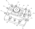
6 is an enlarged perspective view of the leveling pedestal;
7 is an assembled perspective view of the leveling unit.
8 is a plan view of FIG. 7 showing an extremely schematic leveling block;
이하, 본 발명에 따른 공작기계용 크로스 레일의 상하 밸런스를 위한 유압 실린더 장치의 실시예를 도 2 내지 도 8을 참조하여 설명하면 다음과 같다.Hereinafter, an embodiment of a hydraulic cylinder device for vertical balance of a cross rail for a machine tool according to the present invention will be described with reference to FIGS. 2 to 8.
도 2는 본 발명의 일 실시예에 따른 크로스 레일의 상하 밸런스를 위한 유압 실린더 장치가 적용되는 공작기계의 구성도이다.2 is a block diagram of a machine tool to which a hydraulic cylinder device for vertical balance of a cross rail according to an embodiment of the present invention is applied.
이 도면에 도시된 공작기계는 크로스 레일(116)이 상하 방향인 W축을 따라 이송될 수 있는 대형 공작기계로서, 공작물이 적재되는 베드(110)와, 베드(110) 상에 조립되는 테이블(111)과, 베드(110)의 좌우에 조립되는 한 쌍의 컬럼(112)을 구비한다.The machine tool shown in this drawing is a large machine tool in which the
컬럼(112)의 상부에는 탑 빔(119)이 조립되며, 한 쌍의 컬럼(112)의 가이드면을 따라 W축을 따라 이송 가능하게 크로스 레일(116)이 마련된다.The
크로스 레일(116)의 전방에는 수평 방향인 도 2의 좌우 방향을 따라 이송되는 새들 유닛(118)이 조립되고, 새들 유닛(118)의 내부에는 램 유닛(117)이 배치되어 역시 W축을 따라 이송된다.In the front of the
이러한 도 2의 대형 공작기계는 크로스 레일(116)이 W축으로 이송될 수 있는 구조를 가지기 때문에, 공작물의 가공 시 이송모터(115)에 의해 크로스 레일(116)이 먼저 하방으로 이송된 후에 램 유닛(117)이 이송된다. 때문에, 램 유닛(117)이 돌출 길이가 아주 작아 가공 작업 시 떨림 현상 없이 안정적일 수 있다.Since the large machine tool of FIG. 2 has a structure in which the
하지만, 앞서도 기술한 바와 같이, 크로스 레일(116), 램 유닛(117) 및 새들 유닛(118) 모두가 W축으로 이송되는 구조물이고, 또한 이들의 하중이 대략 수십 톤에 달하기 때문에, 이들의 동작을 이송모터(115) 혼자 담당하기에는 한계가 따른다.However, as previously described, since the
따라서 보통은 도 2처럼 유압 실린더 장치(120)가 부가되어 W축 방향의 이송을 보조하게 된다.Therefore, the
다만, 유압 실린더 장치(120)를 도 2와 같은 대형 공작기계에 부가함에 있어, 종래 기술의 경우에는 도 1처럼 유압 실린더 장치(20)의 하단부 영역을 컬럼(12)의 돌출된 전방부(12a)에 파묻는 형태로 가공 및 설치하여 왔기 때문에 컬럼(12)의 소재비 및 가공비 등의 원가 상승이 유발되고, 특히 이러한 작업으로 인해 W축 발란스 정도 조정 작업을 수행하기가 어려워 크로스 레일(116)의 상하 밸런스를 맞추기가 용이하지 않은 문제점을 유발시켰다.However, in adding the
하지만, 본 실시예의 경우에는 아래에서 설명하는 것처럼 유압 실린더 장치(120)를 설치면에 지지시킨 후에, 그 위치를 조정하면서 크로스 레일(116)을 지지하는 구조를 가지기 때문에, 소재비 및 가공비 등의 원가 상승의 유발 문제를 해소할 수 있고, 무엇보다도 간단하고도 단순한 구조로서 W축 발란스 정도 조정 작업을 간편하게 수행할 수 있어 크로스 레일(116)의 상하 밸런스를 용이하게 맞출 수 있게 된다.However, in the present embodiment, since the
이하, 도 8 내지 도 8을 참조하여 본 실시예의 공작기계용 크로스 레일(116)의 상하 밸런스를 위한 유압 실린더 장치(120)에 대해 자세히 설명하도록 한다.Hereinafter, the
도 3은 도 2의 A 영역의 확대도, 도 4는 도 2에 도시된 유압 실린더 장치의 분해 사시도, 도 5는 도 4의 요부 확대도, 도 6은 레벨링 받침대의 확대 사시도, 도 7은 레벨링 유닛의 조립 사시도, 그리고 도 8은 레벨링 블록을 극히 개략적으로 도시한 도 7의 평면도이다.FIG. 3 is an enlarged view of region A of FIG. 2, FIG. 4 is an exploded perspective view of the hydraulic cylinder device shown in FIG. 2, FIG. 5 is an enlarged view of a main portion of FIG. 4, FIG. 6 is an enlarged perspective view of a leveling pedestal, and FIG. 7 is a leveling. Assembled perspective view of the unit, and FIG. 8 is a plan view of FIG. 7 showing an extremely schematic leveling block.
이들 도면에 도시된 바와 같이, 본 실시예의 유압 실린더 장치(120)는, 크게 유압 실린더(130)와 레벨링 유닛(140)의 구조로 간단하게 마련될 수 있다.As shown in these figures, the
유압 실린더(130)는 도 4 및 도 5에 도시된 바와 같이, 실린더 본체(131)와, 실린더 본체(131)에 대해 길이 연장 또는 축소되는 실린더 로드(132)를 구비한다.The
실린더 본체(131)의 하단부는 레벨링 유닛(140)과 연결되며, 실린더 로드(132)의 상단부는 크로스 레일(116)에 결합되어 크로스 레일(116)을 지지한다.The lower end of the
실린더 로드(132)의 상단부에는 너트 유닛(133)이 결합되어 크로스 레일(116)의 밑면에 쐐기식으로 조립될 수 있다.The
레벨링 유닛(140)은 그 하단부가 도 2에 도시된 공작기계와는 이격된 위치에서 공작기계가 설치되는 설치면, 예컨대 지면에 견고하게 고정되어 유압 실린더(130)를 지지하며, 크로스 레일(116)의 상하 밸런스를 위하여 설치면에 대해 크로스 레일(116)을 지지하는 유압 실린더(130)를 설치면 상의 X축 또는 Y축 방향(도 8 참조)으로 위치 이동시키는 역할을 한다.The leveling
이처럼 레벨링 유닛(140)이 설치면에 지지됨에 따라 종래처럼 불필요하게 컬럼(112)의 사이즈를 거대하게 유지하거나 혹은 종래처럼 컬럼(112)을 다시 파내어 작업하는 등의 소재비 및 가공비 상승 문제를 적절하게 해소할 수 있다.As the
레벨링 유닛(140)에 대해 구체적으로 살펴보면, 레벨링 유닛(140)은 레벨링 받침대(150), 레벨링 블록(160), 그리고 다수의 가압부재(170a~170d)를 구비한다.Looking at the
레벨링 받침대(150)는 도 3에 도시된 바와 같이, 설치면에 고정되는 부분이다. 즉 지면에 기초공사를 통해 단단히 고정되어 크로스 레일(116) 등의 중량을 지지한다.The leveling
레벨링 받침대(150)가 설치면, 즉 지면에 단단히 고정되고 또한 수평도를 유지할 수 있도록 레벨링 받침대(150)의 판면에는 적어도 삼각 구도로 배치된 다수의 통공(152)이 형성되며, 통공(152)들을 통해 수직 방향으로 배치된 다수의 앵커(154)가 통과되어 설치면에 체결된다.A plurality of through
다시 말해, 공작기계 기초 공사 시 미리 정해진 위치에 기초 작업을 수행하고 공작기계를 설치할 때, 미리 결정된 위치에 도 6에 도시된 레벨링 받침대(150)를 배치하고 가로 및 세로 방향으로 수준기(155a,155b)를 올려 레벨을 확인한 후, 모르타르를 주입하여 도 3처럼 레벨링 받침대(150)를 지면에 견고하게 고정하게 된다.In other words, when performing the basic work at a predetermined position and installing the machine tool during the construction of the machine tool foundation, the leveling
이러한 레벨링 받침대(150)의 상면에는 그 둘레 방향을 따라 다수의 브래킷(151a~151d)이 마련된다. 브래킷(151a~151d)은 판면에 홀(hole)이 형성된 블록 구조를 가질 수 있는데, 그 형상이 반드시 도시된 것에 제한될 필요는 없다.The upper surface of the leveling
레벨링 블록(160)은 다수의 브래킷(151a~151d) 사이에서 레벨링 받침대(150)의 상부에 위치되고 유압 실린더(130)의 실린더 본체(131)와 연결된다. 이를 위해, 레벨링 블록(160)의 상부에는 볼 와셔(161)가 더 개재된다.The leveling
볼 와셔(161)는 실린더 본체(131)의 하단부에 형성되는 샤프트(131a)가 끼워져 완전히 밀착되도록 중심부가 관통된 구조를 갖는다. 때문에, 실린더 본체(131)의 임의 이동이 저지된다. 이러한 볼 와셔(161)는 두 부품이 구 형상으로 맞물려서 유압 실린더(130)가 레벨링 블록(160)에 매끄럽게 안착되도록 한다.The
레벨링 블록(160)의 내부에는 가압핀(162)에 의해 이동될 수 있는 이동편(163)이 더 구비되다. 이동편(163)은 레벨링 블록(160) 내에서 쐐기 형태로 마련될 수 있다.Inside the leveling
다수의 가압부재(170a~170d)는, 다수의 브래킷(151a~151d)에 각각 전진 또는 후퇴 가능하게 결합되되 해당 위치에서 레벨링 블록(160)을 선택적으로 가압하는 역할을 한다. 가압부재(170a~170d)는 도시된 바와 같은 통상의 볼트와 너트로 적용될 수 있는데, 이들을 통틀어 가압부재(170a~170d)라 하기로 한다.The plurality of pressing
이러한 구성을 갖는 본 실시예의 유압 실린더 장치(120)를 설치하고자 할 때는, 우선 지면에 기초공사를 통해 레벨링 받침대(150)를 단단히 고정시키고, 이어 그 상부로 레벨링 블록(160)과 볼 와셔(161)를 조립한다.When installing the
그 다음에, 볼 와셔(161)에 실린더 본체(131)의 하단부를 연결하고, 실린더 로드(132)의 상단부는 너트 유닛(133)을 통해 크로스 레일(116)의 밑면에 조립하면 된다.Then, the lower end of the
이처럼 유압 실린더(130)를 설치하려 할 때는, 크로스 레일(116)의 상하 밸런스를 고려하여 그 축선에 일치가 되도록 유압 실린더(130)를 설치해야 하는데, 레벨링 받침대(150)는 지면에 고정된 상태이므로 레벨링 받침대(150)에 대해 유압 실린더(130)를 지지하는 레벨링 블록(160)을 도 8의 X축 또는 Y축 방향으로 위치 이동시키면서 조정하면 된다.When the
예컨대, 유압 실린더(130)를 지지하는 레벨링 블록(160)이 도 8의 -X 방향으로 이동되어야 한다면 제3 가압부재(170c)를 느슨히 푼 상태에서 제1 가압부재(170a)를 조여 레벨링 블록(160)을 가압하면 되고, 레벨링 블록(160)이 도 8의 +X 방향으로 이동되어야 한다면 제1 가압부재(170a)를 느슨히 푼 상태에서 제3 가압부재(170c)를 조여 레벨링 블록(160)을 가압하면 된다. 물론, 조정이 완료된 후에는 모든 가압부재(170a~170d)를 조여 고정해야 한다.For example, if the leveling
만약, 레벨링 블록(160)이 도 8의 -Y 방향으로 이동되어야 한다면 제2 가압부재(170b)를 느슨히 푼 상태에서 제4 가압부재(170d)를 조여 레벨링 블록(160)을 가압하면 되고, 레벨링 블록(160)이 도 8의 +Y 방향으로 이동되어야 한다면 제4 가압부재(170d)를 느슨히 푼 상태에서 제2 가압부재(170b)를 조여 레벨링 블록(160)을 가압하면 된다.If the
이와 같은 방법으로 간단하게 레벨링 블록(160)을 평면상 X축 또는 Y축 방향의 위치, 다시 말해 좌우/전후 방향으로 정도 작업을 용이하게 수행함으로써 결과적으로 크로스 레일(116)의 상하 밸런스를 고려하여 크로스 레일(116)의 축선에 일치가 되도록 유압 실린더(130)를 설치할 수 있게 된다.In this way, the leveling
이와 같이, 본 실시예에 따르면, 불필요하게 컬럼(112)의 사이즈를 거대하게 유지하거나 혹은 종래처럼 컬럼(112)을 다시 파내어 작업하는 등의 소재비 및 가공비 상승 문제를 적절하게 해소할 수 있으며, 무엇보다도 간단하고도 단순한 구조로서 W축 발란스 정도 조정 작업을 간편하게 수행할 수 있어 크로스 레일의 상하 밸런스를 용이하게 맞출 수 있게 된다.Thus, according to this embodiment, it is possible to appropriately solve the problem of material cost and processing cost increase, such as unnecessarily maintaining the size of the
뿐만 아니라 구조적으로 안정되기 때문에, 수명이 반영구적일 수 있으며, 고장이 없을 수 있는데, 만약 고장이 나더라도 유지 보수를 쉽게 할 수 있다.In addition, because it is structurally stable, the life can be semi-permanent, there can be no failure, even if a failure can be easily maintained.
이와 같이 본 발명은 기재된 실시예에 한정되는 것이 아니고, 본 발명의 사상 및 범위를 벗어나지 않고 다양하게 수정 및 변형할 수 있음은 이 기술의 분야에서 통상의 지식을 가진 자에게 자명하다. 따라서 그러한 수정예 또는 변형예들은 본 발명의 특허청구범위에 속한다 하여야 할 것이다.
It will be apparent to those skilled in the art that various modifications and variations can be made in the present invention without departing from the spirit or scope of the invention. Therefore, such modifications or variations will have to be belong to the claims of the present invention.
110 : 베드 111 : 테이블
112 : 컬럼 115 : 이송모터
116 : 크로스 레일 117 : 램 유닛
118 : 새들 유닛 119 : 탑 빔
120 : 유압 실린더 장치 130 : 유압 실린더
131 : 실린더 본체 132 : 실린더 로드
133 : 너트 유닛 140 : 레벨링 유닛
150 : 레벨링 받침대 151a~151d : 브래킷
152 : 통공 154 : 앵커
160 : 레벨링 블록 161 : 볼 와셔
170a~170d : 가압부재110: Bed 111: Table
112: column 115: transfer motor
116: cross rail 117: ram unit
118: Saddle Unit 119: Top Beam
120: hydraulic cylinder device 130: hydraulic cylinder
131: cylinder body 132: cylinder rod
133: nut unit 140: leveling unit
150: leveling
152: through hole 154: anchor
160: leveling block 161: ball washer
170a ~ 170d: Pressing member
Claims (3)
하단부는 상기 공작기계와는 이격된 위치에서 상기 공작기계가 설치되는 설치면에 고정되고 상단부는 상기 실린더 본체(131)를 지지하며, 상기 크로스 레일(116)의 상하 밸런스를 위하여 상기 설치면에 대해 상기 유압 실린더(130)를 상기 설치면 상의 X축 또는 Y축 방향으로 위치 이동시키는 레벨링 유닛(140);을 포함하고,
상기 레벨링 유닛(140)은,
상기 설치면에 고정되며, 상면의 둘레 방향을 따라 다수의 브래킷(151a~151d)이 구비되는 레벨링 받침대(150);
상기 다수의 브래킷(151a~151d) 사이에서 상기 레벨링 받침대(150)의 상부에 위치되고 상기 유압 실린더(130)와 연결되는 레벨링 블록(160); 및
상기 다수의 브래킷(151a~151d)에 각각 전진 또는 후퇴 가능하게 결합되되 해당 위치에서 상기 레벨링 블록(160)을 선택적으로 가압하는 다수의 가압부재(170a~170d);를
포함하는 공작기계용 크로스 레일의 상하 밸런스를 위한 유압 실린더 장치.
A cylinder body 131 and a cylinder rod 132 extending or contracting with respect to the cylinder body 131, the end of the cylinder rod 132 having a cross-rail 116 of a machine tool; Hydraulic cylinder 130 coupled to; And
The lower end is fixed to the installation surface on which the machine tool is installed at a position spaced apart from the machine tool, and the upper end supports the cylinder body 131, and the installation surface for the vertical balance of the cross rail 116. And a leveling unit 140 for moving the hydraulic cylinder 130 in the X-axis or Y-axis direction on the installation surface.
The leveling unit 140,
A leveling pedestal 150 fixed to the installation surface and provided with a plurality of brackets 151a to 151d along the circumferential direction of the upper surface;
A leveling block 160 positioned above the leveling pedestal 150 between the plurality of brackets 151a to 151d and connected to the hydraulic cylinder 130; And
A plurality of pressing members 170a to 170d coupled to the plurality of brackets 151a to 151d so as to be forward or retracted, respectively, and selectively pressurizing the leveling block 160 at a corresponding position;
Hydraulic cylinder device for the vertical balance of the cross rail for machine tools included.
상기 레벨링 받침대(150)의 판면에는 상기 레벨링 받침대(150)를 상기 설치면에 고정시키기 위한 앵커(154)가 통과되는 다수의 통공(152)이 더 형성되며,
상기 다수의 통공(152)은 상기 레벨링 받침대(150)의 판면에서 적어도 삼각 구도로 배치되는 것을 특징으로 하는 공작기계용 크로스 레일의 상하 밸런스를 위한 유압 실린더 장치.
The method of claim 1,
The plate surface of the leveling pedestal 150 is further formed with a plurality of through holes 152 through which the anchor 154 for fixing the leveling pedestal 150 to the installation surface,
The plurality of through holes (152) is a hydraulic cylinder device for the vertical balance of the cross rail for the machine tool, characterized in that arranged at least in a triangular composition on the plate surface of the leveling pedestal (150).
상기 레벨링 블록(160)은,
내부에 가압핀(162)에 의해 이동될 수 있는 이동편(163): 및
상단에는 상기 실린더 본체(131)의 하단부에 형성되는 샤프트(131a)가 조립되어 이동이 저지되는 볼 와셔(161)를 더 구비하며,
상기 이동편(163)은 레벨링 블록(160) 내에서 쐐기 형태로 마련되는 것을 특징으로 하는 공작기계용 크로스 레일의 상하 밸런스를 위한 유압 실린더 장치.The method according to claim 1 or 2,
The leveling block 160,
Moving piece 163 that can be moved by the pressure pin 162 therein: And
The upper end is further provided with a ball washer 161 is assembled to the shaft (131a) formed at the lower end of the cylinder body 131 to prevent movement,
The moving piece (163) is a hydraulic cylinder device for the vertical balance of the cross rail for the machine tool, characterized in that provided in the wedge shape in the leveling block (160).
Priority Applications (1)
| Application Number | Priority Date | Filing Date | Title |
|---|---|---|---|
| KR1020100129705A KR101788867B1 (en) | 2010-12-17 | 2010-12-17 | Cylinder apparatus for up/down balancing cross-rail of machine tool |
Applications Claiming Priority (1)
| Application Number | Priority Date | Filing Date | Title |
|---|---|---|---|
| KR1020100129705A KR101788867B1 (en) | 2010-12-17 | 2010-12-17 | Cylinder apparatus for up/down balancing cross-rail of machine tool |
Publications (2)
| Publication Number | Publication Date |
|---|---|
| KR20120068197A true KR20120068197A (en) | 2012-06-27 |
| KR101788867B1 KR101788867B1 (en) | 2017-10-20 |
Family
ID=46686943
Family Applications (1)
| Application Number | Title | Priority Date | Filing Date |
|---|---|---|---|
| KR1020100129705A KR101788867B1 (en) | 2010-12-17 | 2010-12-17 | Cylinder apparatus for up/down balancing cross-rail of machine tool |
Country Status (1)
| Country | Link |
|---|---|
| KR (1) | KR101788867B1 (en) |
Cited By (4)
| Publication number | Priority date | Publication date | Assignee | Title |
|---|---|---|---|---|
| CN103894841A (en) * | 2014-04-07 | 2014-07-02 | 山东义信重机制造有限公司 | Feeding mechanism for horizontal lathe |
| KR20150074738A (en) | 2013-12-24 | 2015-07-02 | 두산인프라코어 주식회사 | Bed of machine tool |
| KR20160008343A (en) * | 2014-07-14 | 2016-01-22 | 주식회사 세스코 | Bed for machine tools |
| CN107571036A (en) * | 2017-09-27 | 2018-01-12 | 上海明索重型机械股份有限公司 | The dynamic beam retaining mechanism of Digit Control Machine Tool |
Families Citing this family (1)
| Publication number | Priority date | Publication date | Assignee | Title |
|---|---|---|---|---|
| CN110340682A (en) * | 2019-07-09 | 2019-10-18 | 南通远大精密机械有限公司 | A kind of self-balancing vertical machining centre |
-
2010
- 2010-12-17 KR KR1020100129705A patent/KR101788867B1/en active IP Right Grant
Cited By (4)
| Publication number | Priority date | Publication date | Assignee | Title |
|---|---|---|---|---|
| KR20150074738A (en) | 2013-12-24 | 2015-07-02 | 두산인프라코어 주식회사 | Bed of machine tool |
| CN103894841A (en) * | 2014-04-07 | 2014-07-02 | 山东义信重机制造有限公司 | Feeding mechanism for horizontal lathe |
| KR20160008343A (en) * | 2014-07-14 | 2016-01-22 | 주식회사 세스코 | Bed for machine tools |
| CN107571036A (en) * | 2017-09-27 | 2018-01-12 | 上海明索重型机械股份有限公司 | The dynamic beam retaining mechanism of Digit Control Machine Tool |
Also Published As
| Publication number | Publication date |
|---|---|
| KR101788867B1 (en) | 2017-10-20 |
Similar Documents
| Publication | Publication Date | Title |
|---|---|---|
| KR20120068197A (en) | Cylinder apparatus for up/down balancing cross-rail of machine tool | |
| KR20120019400A (en) | Assembling an auxiliary lifting unit on a mobile crane | |
| CN105312798A (en) | Steel structure numerical control assembly center | |
| CN103712811B (en) | Combination beam pre-stress type is hydraulic bracket test-bed | |
| CN211438958U (en) | Multi-direction shock-proof shock absorption base for machine tool | |
| CN112475937A (en) | Lightweight vertical rail type machine tool | |
| CN203804585U (en) | Boring fixture for support of large mechanical travelling mechanism | |
| JP2013223906A (en) | Machine tool and leveling method | |
| CN107020871B (en) | Engraving machine | |
| CN214292782U (en) | Supporting device for cabin | |
| KR101079283B1 (en) | A large-sized cutter which prevent an transformed of working environment | |
| CN210146699U (en) | Machine tool of large bending machine | |
| CN206632660U (en) | A kind of Installing machine tool seat | |
| CN205520213U (en) | Well support assembly welding frock | |
| CN201366488Y (en) | Fixed supporting device of sector section basic framework of continuous casting machine | |
| CN112621286B (en) | Turnover driving assembly and driving method thereof | |
| CN104985595A (en) | A three-axis truss type robot | |
| CN202291985U (en) | Universal welding clamp for frame | |
| CN109571084A (en) | A kind of steel construction piece boring grab | |
| CN218225309U (en) | Support tool for welding movable arm of loader | |
| CN220362171U (en) | Auxiliary welding tool for trailer of tunnel boring machine | |
| CN220112730U (en) | Fixed beam gantry drilling and milling machine working platform structure | |
| CN201316899Y (en) | Base and upright posts for fixed beam type numerical control plane-milling machine body structure | |
| CN110508657A (en) | A kind of continuous punching equipment adjustable working table | |
| KR20150000194U (en) | Step control backing devicee |
Legal Events
| Date | Code | Title | Description |
|---|---|---|---|
| A201 | Request for examination | ||
| E902 | Notification of reason for refusal | ||
| E701 | Decision to grant or registration of patent right | ||
| GRNT | Written decision to grant |