KR20120066660A - Method and system for capturing and utilizing energy generated in a flue gas stream processing system - Google Patents
Method and system for capturing and utilizing energy generated in a flue gas stream processing system Download PDFInfo
- Publication number
- KR20120066660A KR20120066660A KR1020127010373A KR20127010373A KR20120066660A KR 20120066660 A KR20120066660 A KR 20120066660A KR 1020127010373 A KR1020127010373 A KR 1020127010373A KR 20127010373 A KR20127010373 A KR 20127010373A KR 20120066660 A KR20120066660 A KR 20120066660A
- Authority
- KR
- South Korea
- Prior art keywords
- carbon dioxide
- stream
- kpascal
- flue gas
- pressure
- Prior art date
Links
Images
Classifications
-
- B—PERFORMING OPERATIONS; TRANSPORTING
- B01—PHYSICAL OR CHEMICAL PROCESSES OR APPARATUS IN GENERAL
- B01D—SEPARATION
- B01D53/00—Separation of gases or vapours; Recovering vapours of volatile solvents from gases; Chemical or biological purification of waste gases, e.g. engine exhaust gases, smoke, fumes, flue gases, aerosols
- B01D53/14—Separation of gases or vapours; Recovering vapours of volatile solvents from gases; Chemical or biological purification of waste gases, e.g. engine exhaust gases, smoke, fumes, flue gases, aerosols by absorption
- B01D53/1425—Regeneration of liquid absorbents
-
- B—PERFORMING OPERATIONS; TRANSPORTING
- B01—PHYSICAL OR CHEMICAL PROCESSES OR APPARATUS IN GENERAL
- B01D—SEPARATION
- B01D53/00—Separation of gases or vapours; Recovering vapours of volatile solvents from gases; Chemical or biological purification of waste gases, e.g. engine exhaust gases, smoke, fumes, flue gases, aerosols
- B01D53/14—Separation of gases or vapours; Recovering vapours of volatile solvents from gases; Chemical or biological purification of waste gases, e.g. engine exhaust gases, smoke, fumes, flue gases, aerosols by absorption
- B01D53/1456—Removing acid components
- B01D53/1475—Removing carbon dioxide
-
- B—PERFORMING OPERATIONS; TRANSPORTING
- B01—PHYSICAL OR CHEMICAL PROCESSES OR APPARATUS IN GENERAL
- B01D—SEPARATION
- B01D53/00—Separation of gases or vapours; Recovering vapours of volatile solvents from gases; Chemical or biological purification of waste gases, e.g. engine exhaust gases, smoke, fumes, flue gases, aerosols
- B01D53/34—Chemical or biological purification of waste gases
- B01D53/46—Removing components of defined structure
- B01D53/62—Carbon oxides
-
- B—PERFORMING OPERATIONS; TRANSPORTING
- B01—PHYSICAL OR CHEMICAL PROCESSES OR APPARATUS IN GENERAL
- B01D—SEPARATION
- B01D53/00—Separation of gases or vapours; Recovering vapours of volatile solvents from gases; Chemical or biological purification of waste gases, e.g. engine exhaust gases, smoke, fumes, flue gases, aerosols
- B01D53/34—Chemical or biological purification of waste gases
- B01D53/74—General processes for purification of waste gases; Apparatus or devices specially adapted therefor
- B01D53/77—Liquid phase processes
- B01D53/78—Liquid phase processes with gas-liquid contact
-
- F—MECHANICAL ENGINEERING; LIGHTING; HEATING; WEAPONS; BLASTING
- F23—COMBUSTION APPARATUS; COMBUSTION PROCESSES
- F23J—REMOVAL OR TREATMENT OF COMBUSTION PRODUCTS OR COMBUSTION RESIDUES; FLUES
- F23J15/00—Arrangements of devices for treating smoke or fumes
- F23J15/02—Arrangements of devices for treating smoke or fumes of purifiers, e.g. for removing noxious material
- F23J15/04—Arrangements of devices for treating smoke or fumes of purifiers, e.g. for removing noxious material using washing fluids
-
- B—PERFORMING OPERATIONS; TRANSPORTING
- B01—PHYSICAL OR CHEMICAL PROCESSES OR APPARATUS IN GENERAL
- B01D—SEPARATION
- B01D2256/00—Main component in the product gas stream after treatment
- B01D2256/22—Carbon dioxide
-
- B—PERFORMING OPERATIONS; TRANSPORTING
- B01—PHYSICAL OR CHEMICAL PROCESSES OR APPARATUS IN GENERAL
- B01D—SEPARATION
- B01D2257/00—Components to be removed
- B01D2257/50—Carbon oxides
- B01D2257/504—Carbon dioxide
-
- F—MECHANICAL ENGINEERING; LIGHTING; HEATING; WEAPONS; BLASTING
- F23—COMBUSTION APPARATUS; COMBUSTION PROCESSES
- F23J—REMOVAL OR TREATMENT OF COMBUSTION PRODUCTS OR COMBUSTION RESIDUES; FLUES
- F23J2215/00—Preventing emissions
- F23J2215/50—Carbon dioxide
-
- F—MECHANICAL ENGINEERING; LIGHTING; HEATING; WEAPONS; BLASTING
- F23—COMBUSTION APPARATUS; COMBUSTION PROCESSES
- F23J—REMOVAL OR TREATMENT OF COMBUSTION PRODUCTS OR COMBUSTION RESIDUES; FLUES
- F23J2219/00—Treatment devices
- F23J2219/40—Sorption with wet devices, e.g. scrubbers
-
- F—MECHANICAL ENGINEERING; LIGHTING; HEATING; WEAPONS; BLASTING
- F23—COMBUSTION APPARATUS; COMBUSTION PROCESSES
- F23J—REMOVAL OR TREATMENT OF COMBUSTION PRODUCTS OR COMBUSTION RESIDUES; FLUES
- F23J2219/00—Treatment devices
- F23J2219/60—Sorption with dry devices, e.g. beds
-
- Y—GENERAL TAGGING OF NEW TECHNOLOGICAL DEVELOPMENTS; GENERAL TAGGING OF CROSS-SECTIONAL TECHNOLOGIES SPANNING OVER SEVERAL SECTIONS OF THE IPC; TECHNICAL SUBJECTS COVERED BY FORMER USPC CROSS-REFERENCE ART COLLECTIONS [XRACs] AND DIGESTS
- Y02—TECHNOLOGIES OR APPLICATIONS FOR MITIGATION OR ADAPTATION AGAINST CLIMATE CHANGE
- Y02A—TECHNOLOGIES FOR ADAPTATION TO CLIMATE CHANGE
- Y02A50/00—TECHNOLOGIES FOR ADAPTATION TO CLIMATE CHANGE in human health protection, e.g. against extreme weather
- Y02A50/20—Air quality improvement or preservation, e.g. vehicle emission control or emission reduction by using catalytic converters
-
- Y—GENERAL TAGGING OF NEW TECHNOLOGICAL DEVELOPMENTS; GENERAL TAGGING OF CROSS-SECTIONAL TECHNOLOGIES SPANNING OVER SEVERAL SECTIONS OF THE IPC; TECHNICAL SUBJECTS COVERED BY FORMER USPC CROSS-REFERENCE ART COLLECTIONS [XRACs] AND DIGESTS
- Y02—TECHNOLOGIES OR APPLICATIONS FOR MITIGATION OR ADAPTATION AGAINST CLIMATE CHANGE
- Y02C—CAPTURE, STORAGE, SEQUESTRATION OR DISPOSAL OF GREENHOUSE GASES [GHG]
- Y02C20/00—Capture or disposal of greenhouse gases
- Y02C20/40—Capture or disposal of greenhouse gases of CO2
-
- Y—GENERAL TAGGING OF NEW TECHNOLOGICAL DEVELOPMENTS; GENERAL TAGGING OF CROSS-SECTIONAL TECHNOLOGIES SPANNING OVER SEVERAL SECTIONS OF THE IPC; TECHNICAL SUBJECTS COVERED BY FORMER USPC CROSS-REFERENCE ART COLLECTIONS [XRACs] AND DIGESTS
- Y02—TECHNOLOGIES OR APPLICATIONS FOR MITIGATION OR ADAPTATION AGAINST CLIMATE CHANGE
- Y02E—REDUCTION OF GREENHOUSE GAS [GHG] EMISSIONS, RELATED TO ENERGY GENERATION, TRANSMISSION OR DISTRIBUTION
- Y02E20/00—Combustion technologies with mitigation potential
- Y02E20/32—Direct CO2 mitigation
Abstract
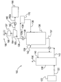
연도 가스 처리 시스템(100) 내에 발생된 에너지를 활용하기 위한 시스템 및 방법. 본 방법은 이산화탄소 함유 용액(142)을 재생 시스템(136) 내의 압력을 받게 하고, 그에 의해서 상기 이산화탄소 함유 용액(142)으로부터 이산화탄소를 제거하고 고압 이산화탄소 스트림(138)을 발생시킨다. 고압 이산화탄소 스트림(138)의 적어도 일부는 팽창 터빈(160)으로 도입되고, 그에 의해서 에너지(164)를 발생시킨다. 에너지(164)는 전력(168)을 발생시키는데 사용된다.Systems and methods for utilizing the energy generated in the flue gas treatment system (100). The method subjects the carbon dioxide containing solution 142 to pressure in the regeneration system 136, thereby removing carbon dioxide from the carbon dioxide containing solution 142 and generating a high pressure carbon dioxide stream 138. At least a portion of the high pressure carbon dioxide stream 138 is introduced into the expansion turbine 160, thereby generating energy 164. Energy 164 is used to generate power 168.

Description
본 출원은 2009년 9월 24일자 출원되고 그 전체가 본원에서 참고로 합체되며 발명의 명칭이 "연도 가스 스트림 처리 시스템에서 발생되는 에너지를 포획하여 활용하기 위한 방법 및 시스템"인 미국 임시 특허 출원번호 제 61/245,436호에 대한 우선권을 주장한다.This application is filed on September 24, 2009, incorporated herein by reference in its entirety, and is incorporated herein by reference in its entirety, US Provisional Patent Application No., entitled "Methods and Systems for Capturing and Utilizing Energy Generated in a Flue Gas Stream Treatment System." Claims priority to heading 61 / 245,436.
공시된 주제는 연도 가스 스트림으로부터 이산화탄소(C02)를 제거하기 위한 시스템 및 방법에 관한 것이다. 특히, 공시된 주제는 연도 가스 스트림으로부터 C02를 제거하는 동안 발생되는 에너지를 포획하여 활용하기 위한 시스템 및 방법에 관한 것이다.
The disclosed subject matter relates to a system and method for removing carbon dioxide (C0 2 ) from a flue gas stream. In particular, the disclosed subject matter relates to systems and methods for capturing and utilizing the energy generated during removal of CO 2 from flue gas streams.
전세계에서 사용되는 대부분의 에너지는 석탄, 오일 및 천연 가스와 같이, 탄소 및 수소-함유 연료들의 연소에서 얻어진다. 탄소 및 수소 이외에, 이들 연료들은 산소, 습기 및 애쉬, 황(종종 "SOx"로 칭하는 황 산화물 형태), 질소 화합물(종종 "NOx"로 칭하는 질소 산화물 형태), 염소, 수은 및 기타 미량 원소들을 함유한다. 연소 동안 방출된 오염물들의 위험 영향에 대한 경고로 인해 발전소, 제련소 및 기타 산업 공정들로부터의 방출물들에 대한 더욱 엄격한 제한을 실행하게 되었다. 거의 제로에 근접한 오염물 방출을 달성하기 위하여 상기 산업장의 작업자들에 대한 압력이 증가하고 있다.Most of the energy used around the world comes from the combustion of carbon and hydrogen-containing fuels, such as coal, oil and natural gas. In addition to carbon and hydrogen, these fuels contain oxygen, moisture and ash, sulfur (often in the form of sulfur oxides called "SOx"), nitrogen compounds (often in the form of nitrogen oxides called "NOx"), chlorine, mercury and other trace elements do. Warnings of the dangerous effects of pollutants released during combustion have led to stricter restrictions on emissions from power plants, smelters and other industrial processes. The pressure on workers in the industry is increasing to achieve pollutant emissions near zero.
다수의 방법 및 시스템들이 거의 제로에 근접한 오염물 방출을 달성하는데 반응하여 발전되었다. 시스템 및 방법은 탈황 시스템들(습식 연도 가스 탈황 시스템들("WFGD") 및 건식 연도 가스 탈황 시스템들("DFGD")), 미립자 필터(예로서 백 하우스, 미립자 집전체 등을 포함함) 뿐 아니라, 연도 가스로부터 오염물들을 흡수하는 하나 이상의 흡수제의 사용을 포함하지만, 이들에 국한되지 않는다. 흡수제의 예들은 활성 탄소, 암모니아, 석회석 등을 포함하지만, 이들에 국한되지 않는다.Many methods and systems have been developed in response to achieving pollutant emissions close to zero. The system and method includes only desulfurization systems (wet flue gas desulfurization systems ("WFGD") and dry flue gas desulfurization systems ("DFGD")), particulate filters (such as bag houses, particulate current collectors, etc.). It does not include, but is not limited to, the use of one or more absorbents to absorb contaminants from the flue gas. Examples of absorbents include, but are not limited to, activated carbon, ammonia, limestone, and the like.
암모니아 뿐 아니라, 아민 용액들은 연도 가스 스트림으로부터 C02 뿐 아니라 이산화황(S02) 및 염화수소(HC1)를 효과적으로 제거하는 것으로 알려졌다. 하나의 특정 적용예에서, 연도 가스 스트림으로부터의 C02를 암모니로 흡수 및 제거하는 것은 저온, 예로서, 0℃ 내지 20℃ 사이에서 실행된다.
In addition to ammonia, amine solutions have been found to effectively remove sulfur dioxide (S0 2 ) and hydrogen chloride (HC1) as well as CO 2 from the flue gas stream. In one particular application, the absorption and removal of C0 2 from the flue gas stream with ammonia is carried out at low temperatures, for example between 0 ° C and 20 ° C.
연도 가스 스트림으로부터 오염물들의 제거는 상당량의 에너지를 필요로 한다. 연도 가스 스트림 처리 시스템 내의 오염물들을 제거 및 처리하는 동안 발생된 에너지를 사용하면 그 시스템에 의해서 요구되는 비용 및 자원을 감소시킬 수 있다.Removal of contaminants from the flue gas stream requires significant amounts of energy. The use of energy generated during the removal and treatment of contaminants in the flue gas stream treatment system can reduce the cost and resources required by the system.
본원에 예시된 형태들에 따라서, 연도 가스 처리 시스템 내에서 발생되는 에너지를 활용하기 위한 방법이 제공되며, 이 방법은 연도 가스 처리 시스템 내의 재생 시스템으로 이산화탄소 함유 용액을 제공하는 단계; 상기 이산화탄소 함유 용액을 상기 재생 시스템 내의 압력을 받게 하고 그에 의해서, 상기 이산화탄소 함유 용액으로부터 이산화탄소를 제거하고 고압 이산화탄소 스트림 및 감소된 이산화탄소 수용 용액을 생성하는 단계; 상기 고압 이산화탄소 스트림의 적어도 일부를 팽창 터빈으로 도입하여 상기 고압 이산화탄소 스트림의 압력을 감소시키고, 그에 의해서 에너지 및 저압 이산화탄소 스트림을 생성하는 단계; 및 상기 팽창 터빈 내에 발생된 에너지를 활용하여 전력을 발생시키고, 그에 의해서 연도 가스 처리 시스템 내에 발생된 에너지를 활용하는 단계를 포함한다.In accordance with aspects exemplified herein, a method for utilizing energy generated in a flue gas treatment system is provided, the method comprising providing a carbon dioxide containing solution to a regeneration system in a flue gas treatment system; Subjecting the carbon dioxide containing solution to pressure in the regeneration system thereby removing carbon dioxide from the carbon dioxide containing solution and producing a high pressure carbon dioxide stream and a reduced carbon dioxide receiving solution; Introducing at least a portion of the high pressure carbon dioxide stream into an expansion turbine to reduce the pressure of the high pressure carbon dioxide stream, thereby producing an energy and low pressure carbon dioxide stream; And generating power by utilizing the energy generated in the expansion turbine, thereby utilizing the energy generated in the flue gas treatment system.
본원에 예시된 다른 형태들에 따라서, 연도 가스 스트림으로부터 제거된 이산화탄소의 처리 동안 발생된 에너지를 활용하기 위한 시스템이 제공되며, 이 시스템은 이산화탄소 수용 연도 가스 스트림을 받도록 구성된 흡수 시스템으로서, 상기 이산화탄소 수용 연도 가스 스트림은 상기 흡수 시스템 내의 이산화탄소 제거 용액과 접촉하여 감소된 이산화탄소 수용 연도 가스 스트림 및 이산화탄소 함유 용액을 형성하는 상기 흡수 시스템; 상기 이산화탄소 함유 용액을 받도록 구성된 재생 시스템으로서, 고압 이산화탄소 스트림 및 감소된 이산화탄소 수용 용액을 발생시키는 상기 재생 시스템; 상기 고압 이산화탄소 스트림의 압력을 감소시켜서 저압 이산화탄소 스트림 및 에너지를 생성하기 위하여, 상기 고압 이산화탄소 스트림의 적어도 일부를 받도록 구성된 팽창 터빈; 및 상기 팽창 터빈과 교통하고, 상기 팽창 터빈으로부터의 에너지를 활용하여 전기를 발생시키는 제네레이터를 포함한다. According to other aspects exemplified herein, a system is provided for utilizing energy generated during treatment of carbon dioxide removed from a flue gas stream, the system being an absorption system configured to receive a carbon dioxide receiving flue gas stream, wherein the carbon dioxide receiving The flue gas stream is in contact with the carbon dioxide removal solution in the absorption system to form a reduced carbon dioxide containing flue gas stream and a carbon dioxide containing solution; A regeneration system configured to receive the carbon dioxide containing solution, the regeneration system generating a high pressure carbon dioxide stream and a reduced carbon dioxide receiving solution; An expansion turbine configured to receive at least a portion of the high pressure carbon dioxide stream to reduce the pressure of the high pressure carbon dioxide stream to produce a low pressure carbon dioxide stream and energy; And a generator in communication with the expansion turbine and generating electricity by utilizing energy from the expansion turbine.
본원에 예시된 다른 형태들에 따라서, 연도 가스 스트림으로부터 이산화탄소의 제거 동안 발생된 에너지를 재순환하기 위한 방법이 제공되며, 이 방법은 이산화탄소 수용 연도 가스 스트림을 흡수 시스템에 제공하는 단계; 상기 이산화탄소 수용 연도 가스 스트림을 이산화탄소 제거 용액과 접촉시키고, 그에 의해서 상기 연도 가스 스트림으로부터 이산화탄소를 제거하고 감소된 이산화탄소 수용 연도 가스 스트림 및 이산화탄소 함유 용액을 형성하는 단계; 상기 이산화탄소 함유 용액을 1723.7 kpascal 내지 3447.4 kpascal 범위의 압력을 받게 하고, 그에 의해서 고압 이산화탄소 스트림 및 감소된 이산화탄소 수용 용액을 형성하는 단계로서, 상기 고압 이산화탄소 스트림은 1723.7 kpascal 내지 3447.4 kpascal 범위의 압력을 가지는 단계; 상기 고압 이산화탄소 스트림의 압력을 감소시켜서 저압 이산화탄소 스트림 및 에너지를 형성하는 단계로서, 상기 저압 이산화탄소 스트림은 68.9 kpascal 내지 689.5 kpascal 범위의 압력을 가지는 단계; 및 상기 에너지를 활용하여 상기 흡수 시스템에 전기를 제공하고, 그에 의해서 연도 가스 스트림으로부터 이산화탄소의 제거 동안 발생된 에너지를 재순환하는 단계를 포함한다.In accordance with other aspects exemplified herein, a method is provided for recycling energy generated during removal of carbon dioxide from a flue gas stream, the method comprising providing a carbon dioxide receiving flue gas stream to an absorption system; Contacting the carbon dioxide containing flue gas stream with a carbon dioxide removal solution, thereby removing carbon dioxide from the flue gas stream and forming a reduced carbon dioxide containing flue gas stream and a carbon dioxide containing solution; Subjecting the carbon dioxide containing solution to pressure in the range of 1723.7 kpascal to 3447.4 kpascal, thereby forming a high pressure carbon dioxide stream and a reduced carbon dioxide receiving solution, wherein the high pressure carbon dioxide stream has a pressure in the range of 1723.7 kpascal to 3447.4 kpascal. ; Reducing the pressure of the high pressure carbon dioxide stream to form a low pressure carbon dioxide stream and energy, the low pressure carbon dioxide stream having a pressure ranging from 68.9 kpascal to 689.5 kpascal; And utilizing the energy to provide electricity to the absorption system, thereby recycling energy generated during removal of carbon dioxide from the flue gas stream.
상기 설명 및 기타 형태들은 이하 도면 및 상세 설명에 의해서 예시된다.The above description and other forms are exemplified by the following drawings and detailed description.
이하, 예시적인 실시예인 도면을 참조하고, 유사 요소들은 유사 번호로 기재된다.Reference is now made to the drawings, which are exemplary embodiments, in which like elements are described by like numerals.
도 1은 연도 가스 스트림으로부터 오염물들을 제거하는데 활용되는 연도 가스 스트림 처리 시스템의 개략도.
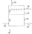
도 2는 도 1에 도시된 시스템 내에 사용되는 흡수 시스템의 일 실시예의 예시도.1 is a schematic diagram of a flue gas stream treatment system utilized to remove contaminants from a flue gas stream.
FIG. 2 is an illustration of one embodiment of an absorption system for use within the system shown in FIG. 1. FIG.
일 실시예는 도 1에 도시된 바와 같이, 연도 가스 스트림(120)으로부터 오염물들을 제거하기 위한 시스템(100)을 포함한다. 연도 가스 스트림(120)은 노(122) 내에 있는 연료의 연소에 의해서 발생된다. 연도 가스 스트림(120)은 황 산화물(SOx), 질소 산화물(NOx) 뿐 아니라 수은(Hg), 염화수소(HCl), 미립자 물질, C02, 등을 포함하는 다수의 오염물들을 포함하지만, 이들에 국한되지 않는다. 도 1에 도시되지 않았지만, 연도 가스 스트림(120)은 예로서, 연도 가스로부터 SOx 및 미립자들을 제거할 수 있는 연도 가스 탈황 공정 및 미립자 집진기에 의한 처리와 같이, 오염물질을 제거하는 처리 과정을 겪을 수 있다.One embodiment includes a
여전히 도 1에 있어서, 연도 가스 스트림(120)은 흡수 시스템(130)을 통해서 연도 가스 스트림(120)을 통과시킴으로써 CO2를 제거하는 처리를 겪을 수 있다. 도 1에는 도시되지 않았지만, 연도 가스 스트림(120)은 흡수 시스템(130) 안으로 들어가기 전에 냉각 시스템을 통과해서 진행될 수 있다는 것을 예상할 수 있다. 냉각 시스템은 연도 가스 스트림(120)이 주위 온도 미만의 온도로 냉각시킬 수 있다.Still in FIG. 1,
도 2에 도시된 바와 같이, 흡수 시스템(130)은 연도 가스 스트림으로부터 CO2의 흡수를 용이하게 하기 위하여 C02 수용 연도 가스 스트림(120)을 (입구 또는 개방부를 통해서) 받도록 구성된다. 연도 가스 스트림(120)으로부터 C02의 흡수는 흡수 시스템(130)으로 공급되는 C02 제거 용액(140)과 연도 가스 스트림을 접촉시킴으로써 이루어진다. 일 실시예에서, C02 제거 용액(140)은 물 용액에 용해된 암모니아 및 CO2 종들을 포함하고 중탄산 암모늄(ammonium bicarbonate)의 침전 고체를 또한 포함할 수 있는 암모니아 처리된 용액 또는 슬러리(140)이다. 다른 실시예에서, C02 제거 용액(140)은 아민 용액이다.As shown in FIG. 2,
일 실시예에서, 흡수 시스템(130)은 제 1 흡수체(132) 및 제 2 흡수체(134)를 포함한다. 흡수 시스템(130)은 이러한 관점에 국한되지 않고 다른 실시예에서는, 도 2에 도시된 흡수체들보다 많거나 또는 작은 수의 흡수체들을 포함할 수 있다.In one embodiment, the
도 2에 상세히 도시된 바와 같이, C02 제거 용액(140)은 흡수 시스템(130)으로 도입된다. 일 실시예에서, C02 제거 용액(140)은 흡수 시스템(130) 내의 방향 B의 연도 가스 스트림(120)의 유동과 역방향으로 흐르는 방향 A로 제 1 흡수체(132) 내의 흡수 시스템으로 도입된다. C02 제거 용액(140)이 연도 가스 스트림(120)과 접촉할 때, 연도 가스 스트림에 제공된 C02는 흡수되어 제거되고, 그에 의해서 흡수 시스템(130)을 나오는 이산화탄소 함유 용액(142)과 감소된 이산화탄소 수용 연도 가스 스트림(150)을 형성한다. 그에 따른 이산화탄소 함유 용액(142)의 적어도 일부는 흡수 시스템(130)으로부터 흡수 시스템의 하류에 있는 재생 시스템(136)으로 운반된다(도 1). 재생 시스템(136)에서, 이산화탄소 함유 용액(142)은 흡수 시스템(130)으로 도입되는 C02 제거 용액(140)을 형성하기 위하여 재생될 수 있다.As shown in detail in FIG. 2, the CO 2 removal solution 140 is introduced into the
CO2 제거 용액(140)은 제 1 흡수체(132) 안으로 도입되는 것으로 예시된 실시예에 도시되었지만, 시스템(100)은 이러한 관점에 국한되지 않는데, 그 이유는 CO2 제거 용액이 대신에 제 2 흡수체(134) 내로 도입되거나 또는 제 1 흡수체 및 제 2 흡수체 모두에 도입될 수 있기 때문이다.Although the CO 2
일 실시예에서, 흡수 시스템(130)은 저온 특히 약 20℃ 미만의 온도에서 작동한다. 일 실시예에서, 흡수 시스템(130)은 약 0 내지 약 20℃의 온도 범위에서 작동한다. 다른 실시예에서, 흡수 시스템(130)은 약 0 내지 약 10℃의 온도 범위에서 작동한다. 그러나, 시스템은 이러한 관점에서 국한되지 않으며, 이는 흡수 시스템이 임의의 온도에서 작동할 수 있다는 것이 예상되기 때문이다.In one embodiment, the
여전히 도 2에서, 감소된 이산화탄소 수용 연도 가스 스트림(150)은 대기 환경으로 방출되기 전에 추가 오염물 제거 공정 및 시스템의 처리를 받는다. 이산화탄소 함유 용액(142)은 재생 시스템(136)으로 제공된다.Still in FIG. 2, the reduced carbon dioxide receiving
다시 도 1에 있어서, 재생 시스템(136)은 감소된 이산화탄소 수용 용액(137) 및 고압 이산화탄소 스트림(138)을 형성하기 위하여, 이산화탄소 함유 용액(142)을 수용하고 이산화탄소 함유 용액으로부터 CO2의 제거를 용이하게 하도록 구성된 임의의 재생 시스템일 수 있다.Again in FIG. 1, the
도 1에 도시된 바와 같이, 재생 시스템(136)은 이산화탄소 함유 용액(142)을 재생 시스템 내로 도입하는 입구(139)를 포함한다. 도 1은 재생 시스템(136) 상의 특정 위치에 위치한 입구(139)를 도시하지만, 입구(139)는 재생 시스템 상의 임의의 위치에 위치할 수 있다는 것을 예상할 수 있다.As shown in FIG. 1, the
일 실시예에서, 재생 시스템(136)은 이산화탄소 함유 용액(142)으로부터 CO2의 제거를 용이하게 하기 위하여 증기(도시생략)를 사용한다. 다른 실시예에서, 재생 시스템은 이산화탄소 함유 용액(142)으로부터 CO2를 제거하기 위하여, 약 1723.7 kpascal(평방 인치당 약 250 파운드[게이지] (psig)) 내지 약 3447.4 kpascal(평방 인치당 약 500 파운드 [게이지] (psig)) 범위의 압력에서 작동한다.다른 실시예에서, 재생 시스템(136)은 이산화탄소 함유 용액(142)으로부터 CO2를 제거하기 위하여 증기 및 압력의 조합을 사용할 수 있다.In one embodiment, the
도 1에 도시된 바와 같이, 재생 시스템(136)에서 발생된 감소된 이산화탄소 수용 용액(137)은 C02 제거 용액(140)과 함께 사용하기 위하여 흡수 시스템(130)으로 제공될 수 있다. 예시된 실시예에는 도시되지 않았지만, 감소된 이산화탄소 수용 용액(137)은 신규 C02 제거 용액(140) 또는 흡수 시스템(130)으로부터 재순환된 C02 제거 용액과 조합될 수 있다. 대안적으로, 그리고 예시된 실시예에서는 도시되지 않았지만, 감소된 이산화탄소 수용 용액(137)은 신규 C02 제거 용액(140) 또는 흡수 시스템(130)으로부터 재순환된 C02 제거 용액과 조합되지 않고 흡수 시스템(130)에 직접 제공될 수 있다.As shown in FIG. 1, the reduced carbon dioxide receiving
일 실시예에서, 이산화탄소 함유 용액(142)은 재생 시스템(136) 내의 압력을 받는다. 약 1723.7 kpascal(평방 인치당 약 250 파운드[게이지] (psig)) 내지 약 3447.4 kpascal(평방 인치당 약 500 파운드 [게이지] (psig)) 범위의 압력에서 재생 시스템(136)이 작동하면, 고압 이산화탄소 스트림(138)을 발생시킨다.In one embodiment, the carbon
고압 이산화탄소 스트림(138)은 약 1723.7 kpascal(평방 인치당 약 250 파운드[게이지] (psig)) 내지 약 3447.4 kpascal(평방 인치당 약 500 파운드 [게이지] (psig)) 범위의 압력을 가진다. 일 실시예에서, 고압 이산화탄소 스트림(138)의 압력은 약 2068.4kpascal(약 300 psig) 내지 약 3447.4 kpascal(약 500 psig) 범위 내에 있다. 다른 실시예에서, 고압 이산화탄소 스트림(138)의 압력은 약 2068.4kpascal(약 300 psig) 내지 약 3102.6 kpascal (약 450 psig)의 범위 내에 있다. 추가 실시예에서, 고압 이산화탄소 스트림(138)의 압력은 약 2068.4 kpascal (약 300 psig)이다.The high pressure
도 1에 도시된 바와 같이, 고압 이산화탄소 스트림(138)은 열 교환기(138a)에 제공되고 차후에 팽창 터빈(160)에 제공된다. 일 실시예에서, 열 교환기(138a)를 통해서 진행한 후에, 고압 이산화탄소 스트림(138)의 적어도 일부는 탈수 유닛(170)에 제공되고, 고압 이산화탄소 스트림(138)의 분리 부분은 팽창 터빈(160)에 제공된다.As shown in FIG. 1, high pressure
탈수 유닛(170)은 고압 이산화탄소 스트림의 그 부분을 재생 시스템(136)으로 뒤로 재순환하기 전에 고압 이산화탄소 스트림(138)으로부터 과도한 습기를 제거한다. 재생 시스템(136)으로 재순환된 고압 이산화탄소 스트림(138)의 습기 함량은 시스템 및 적용상황에 따라서 약 100 ppmv 내지 600 ppmv의 범위 내에 있을 것이다.The
도시되지 않았지만, 모든 고압 이산화탄소 스트림(138)은 재생 시스템(136)으로부터 팽창 터빈(160)으로 제공될 수 있다는 것이 예상된다.Although not shown, it is contemplated that all high pressure carbon dioxide streams 138 may be provided from
팽창 터빈(160)은 고압 이산화탄소 스트림의 압력을 감소시키고 저압 이산화탄소 스트림(162) 및 에너지(164)를 생성하기 위하여, 고압 이산화탄소 스트림(138)의 적어도 일부를 (입구 또는 개방부에 의해서) 받도록 구성된다.
일 실시예에서, 고압 이산화탄소 스트림(138)의 압력은 적어도 50%로 감소되어서 저압 이산화탄소 스트림(162)을 형성한다. 다른 실시예에서, 고압 이산화탄소 스트림(138)의 압력은 적어도 75%로 감소되어서 저압 이산화탄소 스트림(162)을 형성한다.In one embodiment, the pressure of the high pressure
구체적으로, 일 실시예에서, 저압 이산화탄소 스트림(162)의 압력은 약 68.9 kpascal (약 10 psig) 내지 약 1066.6 kpascal (약 140 psig) 범위 내에 있다. 다른 실시예에서,저압 이산화탄소 스트림(162)의 압력은 약 68.9 kpascal (약 10 psig) 내지 약 689.5 kpascal (약 100 psig)의 범위 내에 있다. 또다른 실시예에서, 저압 이산화탄소 스트림(162)의 압력은 약 68.9 kpascal (약 10 psig) 내지 약 620.5 kpascal (약 90 psig)의 범위 내에 있다. 추가 실시예에서, 저압 이산화탄소 스트림(162)의 압력은 약 137.9 kpascal (약 20 psig) 내지 약 206.8 kpascal (30 psig)의 범위 내에 있다. 추가 실시예에서, 저압 이산화탄소 스트림(162)의 압력은 약 137.9 kpascal (약 20 psig)이다.Specifically, in one embodiment, the pressure of the low pressure
도 1에 도시된 바와 같이, 저압 이산화탄소 스트림(162)은 저압 이산화탄소 스트림(162a)을 저장 용기(166)에 제공하기 전에 냉각기(165)로 보내진다. 저압 이산화탄소 스트림(162)은 액화되어서 냉각기(165)에서 약 10℃ 내지 80℃의 온도로 냉각된다. 팽창 터빈(160)의 압력 팽창으로부터 발생하는 저압 이산화탄소 스트림(162)의 온도 감소는 냉각기(165)에 의해서 요구되는 에너지를 감소시키고 저압 이산화탄소 스트림의 온도를 액화점으로 낮춘다.As shown in FIG. 1, low pressure
일 실시예에서, 저압 이산화탄소 스트림(162a)은 사용을 위해 또는 추가 처리공정을 위해서 다른 위치로 이송되기 전에 단지 임시적으로 저장 용기(166)에 저장된다.In one embodiment, low pressure
팽창 터빈(160)에서 저압 이산화탄소 스트림(162)을 발생시키기 위하여, 고압 이산화탄소 스트림(138)의 압력을 감소시키면, 또한 에너지(164)를 생성하게 된다. 일 실시예에서, 에너지(164)는 팽창 터빈(160)의 샤프트를 회전시키는 적업 형태이고, 이는 교대로 제네레이터(167)와 같은 장비 부재를 구동시키는데 사용된다. 이해할 수 있는 바와 같이, 고압 이산화탄소 스트림(138)은 팽창 터빈(160)에서 일정 엔트로피의 팽창을 겪게 되고 저온을 갖는 저압 이산화탄소 스트림(162)으로서 나오게 된다.In order to generate the low pressure
도 1에 도시된 바와 같이, 에너지(164)는 전력(168)을 생성하기 위하여 제네레이터(167)에 의해서 사용된다. 제네레이터(167)는 전력(168)을 생성하기 위하여 팽창 터빈(160)에 의해서 제공되는 에너지(164)의 변형을 용이하게 하는 임의의 유형의 제네레이터일 수 있다. 일 실시예에서, 제네레이터(167)는 전기를 전력(168)으로 생성하기 위한 발전기이다.As shown in FIG. 1,
다른 실시예에서, 팽창 터빈(160)은 펌프, 압축기, 냉동 압축기, 팬, 송풍기 등과 같은, 분리된 장비 부재에 연결될 수 있다. 에너지(164)는 팽창 터빈(160)에 결합된 장비에 전력을 제공하는데 사용될 수 있다. 즉, 에너지는 팽창 터빈에 결합된 장비의 주요 운동원일 수 있다.In other embodiments,
제네레이터(167)에 의해서 생성된 전력(168)은 시스템(100) 내에 사용될 수 있다. 예를 들어, 전력(168)은 발전소(122)에 제공되어서 발전소에서 사용될 수 있다. 다른 예에서, 전력(168)은 시스템(100) 내의 여러 디바이스들에 제공되어서 상기 여러 디바이스들에 의해서 사용되며, 상기 여러 디바이스들은 흡수 시스템(130) 내의 펌프, 재생 시스템(136)과 교통하는 펌프, 시스템(100) 내에 사용되는 냉각기 및 응축기, 시스템(100) 내에 사용되는 팬들, 시스템(100) 내에 사용되는 습식 연도 가스 탈황 시스템과 연계하여 사용되는 재순환 펌프 및 볼밀(ball mills)을 포함하지만, 이들에 국한되지 않는다. 대안적으로, 또는 시스템(100) 내의 디바이스들에 전력(168)을 제공하는 것 이외에, 전기 형태의 전력(168)이 소비자 전력망(180) 또는 다른 디바이스 또는 시스템(100)의 외부에 있는 시스템에 제공될 수 있다.
시스템(100) 내의 전력(168)을 사용하면, 시스템 외부에 있는 소스로부터 전력을 얻는데 필요한 설비를 생략, 간소화 또는 제거할 수 있다. 시스템(100) 외부에 있는 소스로부터 전력을 얻는데 필요한 설비를 생략, 간소화 또는 제거함으로써, 외부 소스로부터 전력을 얻는 시스템을 더욱 효율적이고 및/또는 비용 효과적으로 할 수 있다. 효율성 및 비용 감소는 또한 전력(168)이 시스템(100)의 외부로 보내질 때, 소비자 전력망(180)과 같은 시스템 및 디바이스에 의해서 경험하게 된다.Using
본원의 용어 "제 1 " 및 "제 2 " 등은 임의의 순서, 수량 또는 중요성을 의미하는 것이 아니고, 서로 구별하기 위하여 사용되는 것이다. "단수 표현"은 수량의 제한을 의미하는 것이 아니고, 지정된 항목중 적어도 하나의 존재를 지시한다.The terms "first", "second", and the like herein do not mean any order, quantity, or importance, but are used to distinguish each other. "Singular expression" does not mean a limitation of quantity, but rather indicates the presence of at least one of the specified items.
본 발명은 여러 예시적인 실시예를 참조하여 기술되었지만, 당업자는 본 발명의 범주 내에서 다양하게 변형할 수 있고 요소들을 등가 요소들로 대체할 수 있음을 이해할 것이다. 또한, 본 발명의 핵심 범주 내에서 본 발명의 교시에 특정 상황 또는 재료를 적용시키도록 다수의 변형이 가해질 수 있다. 따라서, 본 발명은 본 발명을 실행하기 위하여 고안된 최상의 형태로 개시된 특정 실시예에 국한되지 않고, 본 발명은 첨부된 청구범위의 범주 내의 모든 실시예들을 포함하도록 의도된다.
Although the present invention has been described with reference to various exemplary embodiments, those skilled in the art will understand that various modifications may be made and equivalent elements may be replaced by equivalent elements within the scope of the present invention. In addition, many modifications may be made to adapt a particular situation or material to the teachings of the invention within the core scope of the invention. Thus, it is intended that the invention not be limited to the particular embodiment disclosed as the best form devised for carrying out the invention, but that the invention will include all embodiments falling within the scope of the appended claims.
Claims (21)
연도 가스 처리 시스템 내의 재생 시스템으로 이산화탄소 함유 용액을 제공하는 단계;
상기 이산화탄소 함유 용액을 상기 재생 시스템 내의 압력을 받게 하고 그에 의해서, 상기 이산화탄소 함유 용액으로부터 이산화탄소를 제거하고 고압 이산화탄소 스트림 및 감소된 이산화탄소 수용 용액을 생성하는 단계;
상기 고압 이산화탄소 스트림의 적어도 일부를 팽창 터빈으로 도입하여 상기 고압 이산화탄소 스트림의 압력을 감소시키고, 그에 의해서 에너지 및 저압 이산화탄소 스트림을 생성하는 단계; 및
상기 팽창 터빈 내에 발생된 에너지를 활용하여 전력을 발생시키고, 그에 의해서 연도 가스 처리 시스템 내에 발생된 에너지를 활용하는 단계를 포함하는 방법.A method for utilizing energy generated in a flue gas treatment system,
Providing a carbon dioxide containing solution to a regeneration system in a flue gas treatment system;
Subjecting the carbon dioxide containing solution to pressure in the regeneration system thereby removing carbon dioxide from the carbon dioxide containing solution and producing a high pressure carbon dioxide stream and a reduced carbon dioxide receiving solution;
Introducing at least a portion of the high pressure carbon dioxide stream into an expansion turbine to reduce the pressure of the high pressure carbon dioxide stream, thereby producing an energy and low pressure carbon dioxide stream; And
Utilizing power generated in the expansion turbine to generate power, thereby utilizing energy generated in the flue gas treatment system.
이산화탄소 수용 연도 가스 스트림을 받도록 구성된 흡수 시스템으로서, 상기 이산화탄소 수용 연도 가스 스트림은 상기 흡수 시스템 내의 이산화탄소 제거 용액과 접촉하여 감소된 이산화탄소 수용 연도 가스 스트림 및 이산화탄소 함유 용액을 형성하는 상기 흡수 시스템;
상기 이산화탄소 함유 용액을 받도록 구성된 재생 시스템으로서, 고압 이산화탄소 스트림 및 감소된 이산화탄소 수용 용액을 발생시키는 상기 재생 시스템;
상기 고압 이산화탄소 스트림의 압력을 감소시켜서 저압 이산화탄소 스트림 및 에너지를 생성하기 위하여, 상기 고압 이산화탄소 스트림의 적어도 일부를 받도록 구성된 팽창 터빈; 및
상기 팽창 터빈과 교통하고, 상기 팽창 터빈으로부터의 에너지를 활용하여 전기를 발생시키는 제네레이터를 포함하는 시스템.A system for utilizing energy generated during treatment of carbon dioxide removed from a flue gas stream,
An absorption system configured to receive a carbon dioxide receiving flue gas stream, wherein the carbon dioxide receiving flue gas stream is in contact with the carbon dioxide removal solution in the absorption system to form a reduced carbon dioxide receiving flue gas stream and a carbon dioxide containing solution;
A regeneration system configured to receive the carbon dioxide containing solution, the regeneration system generating a high pressure carbon dioxide stream and a reduced carbon dioxide receiving solution;
An expansion turbine configured to receive at least a portion of the high pressure carbon dioxide stream to reduce the pressure of the high pressure carbon dioxide stream to produce a low pressure carbon dioxide stream and energy; And
And a generator in communication with the expansion turbine and generating electricity by utilizing energy from the expansion turbine.
이산화탄소 수용 연도 가스 스트림을 흡수 시스템에 제공하는 단계;
상기 이산화탄소 수용 연도 가스 스트림을 이산화탄소 제거 용액과 접촉시키고, 그에 의해서 상기 연도 가스 스트림으로부터 이산화탄소를 제거하고 감소된 이산화탄소 수용 연도 가스 스트림 및 이산화탄소 함유 용액을 형성하는 단계;
상기 이산화탄소 함유 용액을 1723.7 kpascal 내지 3447.4 kpascal 범위의 압력을 받게 하고, 그에 의해서 고압 이산화탄소 스트림 및 감소된 이산화탄소 수용 용액을 형성하는 단계로서, 상기 고압 이산화탄소 스트림은 1723.7 kpascal 내지 3447.4 kpascal 범위의 압력을 가지는 단계;
상기 고압 이산화탄소 스트림의 압력을 감소시켜서 저압 이산화탄소 스트림 및 에너지를 형성하는 단계로서, 상기 저압 이산화탄소 스트림은 68.9 kpascal 내지 689.5 kpascal 범위의 압력을 가지는 단계; 및
상기 에너지를 활용하여 상기 흡수 시스템에 전기를 제공하고, 그에 의해서 연도 가스 스트림으로부터 이산화탄소의 제거 동안 발생된 에너지를 재순환하는 단계를 포함하는 방법.
A method for recycling energy generated during removal of carbon dioxide from a flue gas stream,
Providing a carbon dioxide receiving flue gas stream to the absorption system;
Contacting the carbon dioxide containing flue gas stream with a carbon dioxide removal solution, thereby removing carbon dioxide from the flue gas stream and forming a reduced carbon dioxide containing flue gas stream and a carbon dioxide containing solution;
Subjecting the carbon dioxide containing solution to pressure in the range of 1723.7 kpascal to 3447.4 kpascal, thereby forming a high pressure carbon dioxide stream and a reduced carbon dioxide receiving solution, wherein the high pressure carbon dioxide stream has a pressure in the range of 1723.7 kpascal to 3447.4 kpascal. ;
Reducing the pressure of the high pressure carbon dioxide stream to form a low pressure carbon dioxide stream and energy, the low pressure carbon dioxide stream having a pressure ranging from 68.9 kpascal to 689.5 kpascal; And
Utilizing said energy to provide electricity to said absorption system, thereby recycling energy generated during removal of carbon dioxide from a flue gas stream.
Applications Claiming Priority (4)
| Application Number | Priority Date | Filing Date | Title |
|---|---|---|---|
| US24543609P | 2009-09-24 | 2009-09-24 | |
| US61/245,436 | 2009-09-24 | ||
| US12/849,128 US20110068585A1 (en) | 2009-09-24 | 2010-08-03 | Method and system for capturing and utilizing energy generated in a flue gas stream processing system |
| US12/849,128 | 2010-08-03 |
Publications (1)
| Publication Number | Publication Date |
|---|---|
| KR20120066660A true KR20120066660A (en) | 2012-06-22 |
Family
ID=43755976
Family Applications (1)
| Application Number | Title | Priority Date | Filing Date |
|---|---|---|---|
| KR1020127010373A KR20120066660A (en) | 2009-09-24 | 2010-09-15 | Method and system for capturing and utilizing energy generated in a flue gas stream processing system |
Country Status (13)
| Country | Link |
|---|---|
| US (1) | US20110068585A1 (en) |
| EP (1) | EP2480313A1 (en) |
| JP (1) | JP2013505823A (en) |
| KR (1) | KR20120066660A (en) |
| CN (1) | CN102665858A (en) |
| AU (1) | AU2010298537A1 (en) |
| BR (1) | BR112012007436A2 (en) |
| CA (1) | CA2775066A1 (en) |
| IL (1) | IL218781A0 (en) |
| MA (1) | MA33678B1 (en) |
| MX (1) | MX2012003435A (en) |
| RU (1) | RU2012116246A (en) |
| WO (1) | WO2011037788A1 (en) |
Cited By (1)
| Publication number | Priority date | Publication date | Assignee | Title |
|---|---|---|---|---|
| KR101441512B1 (en) * | 2010-01-14 | 2014-11-03 | 알스톰 테크놀러지 리미티드 | Water wash method and system for a carbon dioxide capture process |
Families Citing this family (21)
| Publication number | Priority date | Publication date | Assignee | Title |
|---|---|---|---|---|
| WO2007112570A1 (en) | 2006-04-03 | 2007-10-11 | Pharmatherm Chemicals Inc. | Thermal extraction method and product |
| US20110284359A1 (en) | 2010-05-20 | 2011-11-24 | Uop Llc | Processes for controlling afterburn in a reheater and for controlling loss of entrained solid particles in combustion product flue gas |
| US8499702B2 (en) | 2010-07-15 | 2013-08-06 | Ensyn Renewables, Inc. | Char-handling processes in a pyrolysis system |
| US9441887B2 (en) | 2011-02-22 | 2016-09-13 | Ensyn Renewables, Inc. | Heat removal and recovery in biomass pyrolysis |
| US9347005B2 (en) * | 2011-09-13 | 2016-05-24 | Ensyn Renewables, Inc. | Methods and apparatuses for rapid thermal processing of carbonaceous material |
| US9044727B2 (en) | 2011-09-22 | 2015-06-02 | Ensyn Renewables, Inc. | Apparatuses and methods for controlling heat for rapid thermal processing of carbonaceous material |
| US10400175B2 (en) | 2011-09-22 | 2019-09-03 | Ensyn Renewables, Inc. | Apparatuses and methods for controlling heat for rapid thermal processing of carbonaceous material |
| US10041667B2 (en) | 2011-09-22 | 2018-08-07 | Ensyn Renewables, Inc. | Apparatuses for controlling heat for rapid thermal processing of carbonaceous material and methods for the same |
| US8470077B2 (en) | 2011-11-17 | 2013-06-25 | Alstom Technology Ltd | Low pressure stripping in a gas purification process and systems thereof |
| US9109177B2 (en) | 2011-12-12 | 2015-08-18 | Ensyn Renewables, Inc. | Systems and methods for renewable fuel |
| US20130175004A1 (en) | 2012-01-06 | 2013-07-11 | Alstom Technology Ltd | Gas treatment system with a heat exchanger for reduction of chiller energy consumption |
| KR20130102950A (en) * | 2012-03-09 | 2013-09-23 | 현대자동차주식회사 | Device and method for energy generating after carbon capture |
| US8539749B1 (en) | 2012-04-12 | 2013-09-24 | General Electric Company | Systems and apparatus relating to reheat combustion turbine engines with exhaust gas recirculation |
| US9353682B2 (en) | 2012-04-12 | 2016-05-31 | General Electric Company | Methods, systems and apparatus relating to combustion turbine power plants with exhaust gas recirculation |
| US9670413B2 (en) | 2012-06-28 | 2017-06-06 | Ensyn Renewables, Inc. | Methods and apparatuses for thermally converting biomass |
| US20140150652A1 (en) | 2012-11-30 | 2014-06-05 | Alstom Technology Ltd. | Post absorber scrubbing of so3 |
| AR097135A1 (en) | 2013-06-26 | 2016-02-24 | Ensyn Renewables Inc | SYSTEMS AND METHODS FOR RENEWABLE FUEL |
| EP3337966B1 (en) | 2015-08-21 | 2021-12-15 | Ensyn Renewables, Inc. | Liquid biomass heating system |
| JP6916714B2 (en) * | 2016-11-08 | 2021-08-11 | 株式会社東芝 | Power generation system and condensing absorber |
| EP3565664A4 (en) | 2016-12-29 | 2020-08-05 | Ensyn Renewables, Inc. | Demetallization of liquid biomass |
| CN116196741B (en) * | 2023-04-27 | 2023-07-25 | 中国科学院西北生态环境资源研究院 | Device and method for forming carbon dioxide hydrate by ball milling method |
Family Cites Families (24)
| Publication number | Priority date | Publication date | Assignee | Title |
|---|---|---|---|---|
| US3692506A (en) * | 1970-02-13 | 1972-09-19 | Total Energy Corp | High btu gas content from coal |
| US4270937A (en) * | 1976-12-01 | 1981-06-02 | Cng Research Company | Gas separation process |
| GB1597479A (en) * | 1976-12-01 | 1981-09-09 | Cng Res Co | Gas separation processes |
| JPS60172331A (en) * | 1984-02-20 | 1985-09-05 | Mitsubishi Gas Chem Co Inc | Recovering method of mechanical power |
| GB2165552A (en) * | 1984-10-11 | 1986-04-16 | British Gas Corp | Methanating synthesis gas |
| ZA899705B (en) * | 1989-01-26 | 1990-09-26 | Aeci Ltd | Purification of gases |
| JP2792777B2 (en) * | 1992-01-17 | 1998-09-03 | 関西電力株式会社 | Method for removing carbon dioxide from flue gas |
| NO990812L (en) * | 1999-02-19 | 2000-08-21 | Norsk Hydro As | Method for removing and recovering CO2 from exhaust gas |
| US6209307B1 (en) * | 1999-05-05 | 2001-04-03 | Fpl Energy, Inc. | Thermodynamic process for generating work using absorption and regeneration |
| AU2001276823A1 (en) * | 2000-05-12 | 2001-12-03 | Clean Energy Systems, Inc. | Semi-closed brayton cycle gas turbine power systems |
| DE10210729A1 (en) * | 2002-03-12 | 2003-10-02 | Basf Ag | Process for deacidifying a fluid stream and washing liquid for use in such a process |
| NO20023050L (en) * | 2002-06-21 | 2003-12-22 | Fleischer & Co | Process and facilities for carrying out the process |
| DE10313438A1 (en) * | 2003-03-26 | 2004-11-04 | Uhde Gmbh | Process for the selective removal of hydrogen sulfide and CO2 from raw gas |
| JP4274846B2 (en) * | 2003-04-30 | 2009-06-10 | 三菱重工業株式会社 | Carbon dioxide recovery method and system |
| FR2855984B1 (en) * | 2003-06-10 | 2005-07-22 | Inst Francais Du Petrole | PROCESS FOR TREATING SMOKE |
| NO321817B1 (en) * | 2003-11-06 | 2006-07-10 | Sargas As | Wastewater treatment plants |
| BRPI0514141A (en) * | 2004-08-06 | 2008-05-27 | Eig Inc | Ultra-flue gas cleaning including CO2 removal |
| JP4687184B2 (en) * | 2005-03-29 | 2011-05-25 | 三菱マテリアル株式会社 | Method and apparatus for purifying mixed gas containing acid gas |
| CN1887405A (en) * | 2005-06-27 | 2007-01-03 | 成都华西化工研究所 | Process of removing and recovering CO2 from fume |
| US20070248527A1 (en) * | 2006-04-25 | 2007-10-25 | Spencer Dwain F | Methods and systems for selectively separating co2 from an oxygen combustion gaseous stream |
| US7942008B2 (en) * | 2006-10-09 | 2011-05-17 | General Electric Company | Method and system for reducing power plant emissions |
| US7867322B2 (en) * | 2007-01-31 | 2011-01-11 | Alstom Technology Ltd | Use of SO2 from flue gas for acid wash of ammonia |
| MY155789A (en) * | 2008-03-13 | 2015-11-30 | Shell Int Research | Process for removal of carbon dioxide from a gas |
| DE102008020414A1 (en) * | 2008-04-24 | 2009-10-29 | Leithner, Reinhard, Prof. Dr. techn. | Method for separating carbon dioxide from exhaust gas or synthetic gas from e.g. machine, involves renewing regenerated and separated adsorbent/absorbent, in which adsorber and/or absorber are returned back and used freshly |
-
2010
- 2010-08-03 US US12/849,128 patent/US20110068585A1/en not_active Abandoned
- 2010-09-15 BR BR112012007436A patent/BR112012007436A2/en not_active IP Right Cessation
- 2010-09-15 AU AU2010298537A patent/AU2010298537A1/en not_active Abandoned
- 2010-09-15 RU RU2012116246/05A patent/RU2012116246A/en not_active Application Discontinuation
- 2010-09-15 MX MX2012003435A patent/MX2012003435A/en not_active Application Discontinuation
- 2010-09-15 CN CN201080044117XA patent/CN102665858A/en active Pending
- 2010-09-15 CA CA2775066A patent/CA2775066A1/en not_active Abandoned
- 2010-09-15 WO PCT/US2010/048840 patent/WO2011037788A1/en active Application Filing
- 2010-09-15 EP EP10757353A patent/EP2480313A1/en not_active Withdrawn
- 2010-09-15 JP JP2012530930A patent/JP2013505823A/en active Pending
- 2010-09-15 KR KR1020127010373A patent/KR20120066660A/en not_active Application Discontinuation
-
2012
- 2012-03-22 IL IL218781A patent/IL218781A0/en unknown
- 2012-04-19 MA MA34782A patent/MA33678B1/en unknown
Cited By (1)
| Publication number | Priority date | Publication date | Assignee | Title |
|---|---|---|---|---|
| KR101441512B1 (en) * | 2010-01-14 | 2014-11-03 | 알스톰 테크놀러지 리미티드 | Water wash method and system for a carbon dioxide capture process |
Also Published As
| Publication number | Publication date |
|---|---|
| MX2012003435A (en) | 2012-06-08 |
| JP2013505823A (en) | 2013-02-21 |
| WO2011037788A1 (en) | 2011-03-31 |
| BR112012007436A2 (en) | 2017-05-30 |
| AU2010298537A1 (en) | 2012-04-19 |
| US20110068585A1 (en) | 2011-03-24 |
| CA2775066A1 (en) | 2011-03-31 |
| IL218781A0 (en) | 2012-06-28 |
| MA33678B1 (en) | 2012-10-01 |
| CN102665858A (en) | 2012-09-12 |
| EP2480313A1 (en) | 2012-08-01 |
| RU2012116246A (en) | 2013-10-27 |
Similar Documents
| Publication | Publication Date | Title |
|---|---|---|
| KR20120066660A (en) | Method and system for capturing and utilizing energy generated in a flue gas stream processing system | |
| AU2011259879B2 (en) | Exhaust gas treatment system and method | |
| AU2011259877B2 (en) | Exhaust gas treatment system and method | |
| US9216380B1 (en) | Ammonia stripper for a carbon capture system for reduction of energy consumption | |
| AU2011259873B2 (en) | Air pollution control system and method | |
| WO2012104692A1 (en) | Apparatus and system for nox reduction in wet flue gas | |
| AU2012226513B2 (en) | System and method for low NOx emitting regeneration of desiccants | |
| WO2013144863A1 (en) | A method for processing a power plant flue gas | |
| CN106310847A (en) | Oxygen-enriched combustion boiler flue gas purification and resource recycling system and process | |
| EP2724770A1 (en) | Absorption unit for drying flue gas | |
| US8668892B2 (en) | Method and system for NOx removal from a flue gas | |
| Boos et al. | Method and system for NO x removal from a flue gas | |
| CZ28872U1 (en) | Solid sorbent-based engineering system for catching CO2 from combustion products |
Legal Events
| Date | Code | Title | Description |
|---|---|---|---|
| A201 | Request for examination | ||
| E902 | Notification of reason for refusal | ||
| E601 | Decision to refuse application |