KR20120051722A - Hydraulic power module - Google Patents
Hydraulic power module Download PDFInfo
- Publication number
- KR20120051722A KR20120051722A KR1020127005012A KR20127005012A KR20120051722A KR 20120051722 A KR20120051722 A KR 20120051722A KR 1020127005012 A KR1020127005012 A KR 1020127005012A KR 20127005012 A KR20127005012 A KR 20127005012A KR 20120051722 A KR20120051722 A KR 20120051722A
- Authority
- KR
- South Korea
- Prior art keywords
- hydraulic
- hpm
- servo motor
- motor
- power module
- Prior art date
Links
Images


Classifications
-
- F—MECHANICAL ENGINEERING; LIGHTING; HEATING; WEAPONS; BLASTING
- F15—FLUID-PRESSURE ACTUATORS; HYDRAULICS OR PNEUMATICS IN GENERAL
- F15B—SYSTEMS ACTING BY MEANS OF FLUIDS IN GENERAL; FLUID-PRESSURE ACTUATORS, e.g. SERVOMOTORS; DETAILS OF FLUID-PRESSURE SYSTEMS, NOT OTHERWISE PROVIDED FOR
- F15B1/00—Installations or systems with accumulators; Supply reservoir or sump assemblies
- F15B1/26—Supply reservoir or sump assemblies
-
- F—MECHANICAL ENGINEERING; LIGHTING; HEATING; WEAPONS; BLASTING
- F15—FLUID-PRESSURE ACTUATORS; HYDRAULICS OR PNEUMATICS IN GENERAL
- F15B—SYSTEMS ACTING BY MEANS OF FLUIDS IN GENERAL; FLUID-PRESSURE ACTUATORS, e.g. SERVOMOTORS; DETAILS OF FLUID-PRESSURE SYSTEMS, NOT OTHERWISE PROVIDED FOR
- F15B15/00—Fluid-actuated devices for displacing a member from one position to another; Gearing associated therewith
- F15B15/18—Combined units comprising both motor and pump
-
- F—MECHANICAL ENGINEERING; LIGHTING; HEATING; WEAPONS; BLASTING
- F16—ENGINEERING ELEMENTS AND UNITS; GENERAL MEASURES FOR PRODUCING AND MAINTAINING EFFECTIVE FUNCTIONING OF MACHINES OR INSTALLATIONS; THERMAL INSULATION IN GENERAL
- F16F—SPRINGS; SHOCK-ABSORBERS; MEANS FOR DAMPING VIBRATION
- F16F9/00—Springs, vibration-dampers, shock-absorbers, or similarly-constructed movement-dampers using a fluid or the equivalent as damping medium
- F16F9/32—Details
- F16F9/50—Special means providing automatic damping adjustment, i.e. self-adjustment of damping by particular sliding movements of a valve element, other than flexions or displacement of valve discs; Special means providing self-adjustment of spring characteristics
- F16F9/512—Means responsive to load action, i.e. static load on the damper or dynamic fluid pressure changes in the damper, e.g. due to changes in velocity
- F16F9/5126—Piston, or piston-like valve elements
-
- F—MECHANICAL ENGINEERING; LIGHTING; HEATING; WEAPONS; BLASTING
- F01—MACHINES OR ENGINES IN GENERAL; ENGINE PLANTS IN GENERAL; STEAM ENGINES
- F01L—CYCLICALLY OPERATING VALVES FOR MACHINES OR ENGINES
- F01L1/00—Valve-gear or valve arrangements, e.g. lift-valve gear
- F01L1/20—Adjusting or compensating clearance
- F01L1/22—Adjusting or compensating clearance automatically, e.g. mechanically
- F01L1/24—Adjusting or compensating clearance automatically, e.g. mechanically by fluid means, e.g. hydraulically
- F01L2001/2444—Details relating to the hydraulic feeding circuit, e.g. lifter oil manifold assembly [LOMA]
Abstract
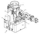
유압력 모듈(10)은, 1) 유압유를 정확한 영역으로 전달하는 유압 매니폴드(12), 2) 유압유(16)를 포함하는 유압 저장부(14), 3) 유압 펌프(18), 4) DC 서보 모터(20), 5) 방향 밸브(22), 6) 냉각 시스템(24), 7) 일체형 필터 하우징(26) 및 8) 전자 장치들 - DC 서보 모터(20)를 제어하는 모터 제어부(28)로 구성된다.The hydraulic force module 10 includes 1) a hydraulic manifold 12 for delivering hydraulic oil to the correct area, 2) a hydraulic reservoir 14 including hydraulic oil 16, 3) a hydraulic pump 18, 4) DC servo motor 20, 5) directional valve 22, 6) cooling system 24, 7) integrated filter housing 26 and 8) electronics-motor control unit for controlling DC servo motor 20 ( 28).
Description
본 발명은 유압력 모듈에 관한 것이다.The present invention relates to a hydraulic force module.
본 출원은 2009년 7월 29일에 출원된 미국 출원 제61/229,298호를 기초로 우선권을 주장하고 상기 미국 출원의 내용은 참조로서 본원에서 도입된다.This application claims priority based on US application 61 / 229,298, filed on July 29, 2009, the contents of which are incorporated herein by reference.
유체 제공을 제어하는 유압력 모듈 및 다른 장치는 매우 잘 알려져 있다.Hydraulic force modules and other devices for controlling fluid delivery are very well known.
본 발명의 목적은, 제어를 과감하게 개선시키고, 기계 장치의 수명을 증가시키고, 간단한 설계를 사용하고, 전력 소비를 감소시키고, 냉각 요건을 감소시키고 노이즈 레벨을 감소시킬 수 있는 유압력 모듈을 제공하는 것에 있다.It is an object of the present invention to provide a hydraulic power module that can drastically improve control, increase the life of a machine, use a simple design, reduce power consumption, reduce cooling requirements and reduce noise levels. It is in doing it.
본 발명의 유압력 모듈은, 1) 유압유(hydraulic fluid)를 정확한 영역으로 전달하는 유압 매니폴드(hydraulic manifold), 2) 유압유가 들어있는 유압 저장부, 3) 유압 펌프, 4) DC 서보 모터(servo motor), 5) 방향 밸브, 6) 냉각 시스템, 7) 일체형 필터 하우징 및 8) 전자 장치들 - DC 서보 모터를 제어하는 모터 제어부로 구성된다.The hydraulic force module of the present invention comprises: 1) hydraulic manifold for delivering hydraulic fluid to the correct area, 2) hydraulic reservoir containing hydraulic oil, 3) hydraulic pump, 4) DC servo motor ( servo motor), 5) directional valve, 6) cooling system, 7) integrated filter housing and 8) electronics-motor control unit for controlling the DC servo motor.
유압력 모듈(HPM)은 유압유를 공급하여 유압 실린더(들)의 다양한 구성부를 작동시키도록 동작한다. DC 서보 모터는 유압 매니폴드를 통하여 유압 펌프에 직접 연결된다. 모터가 회전할 시에, 펌프는 유압유가 매니폴드를 통하여 방향 밸브로 전달되도록 한다. HPM은 유압 실린더의 양 측면으로 흐름을 전환시키도록 방향 밸브에게 신호를 전송한다.The hydraulic force module (HPM) operates to supply hydraulic oil to operate various components of the hydraulic cylinder (s). The DC servo motor is directly connected to the hydraulic pump through the hydraulic manifold. As the motor rotates, the pump allows hydraulic oil to be delivered through the manifold to the directional valve. The HPM sends a signal to the directional valve to divert the flow to both sides of the hydraulic cylinder.
센서(예: 유체 라인의 유량계, 유압 실린더에 결합된 선형 트랜스듀서(linear transducer) 등)와 함께, HPM은 유압 실린더의 피스톤의 속도를 정확하게 제어하는 비율로 유압유를 제공한다. HPM은 또한 유압 실린더 피스톤의 위치가 대향력(opposing force)에 대해 이동이 없도록 유지시킬 수 있다. 이는 정확한 유량(flow rate) 또는 일정한 동압 및 정압(constant dynamic and static pressures)을 생성한다.Together with sensors (eg flow meters in fluid lines, linear transducers coupled to hydraulic cylinders, etc.), HPM provides hydraulic oil at a rate that accurately controls the speed of the pistons in the hydraulic cylinders. The HPM can also keep the position of the hydraulic cylinder pistons free from movement against opposing forces. This produces an accurate flow rate or constant dynamic and static pressures.
본 발명의 시스템에는 다수의 이점이 있고, 본 발명의 시스템은 예를 들면, DC 서보 모터 및 모터 제어기를 사용함으로써 제어를 극적으로 증가시킨다. 또 다른 결과로서, 시스템 기계 장치의 수명은 개선되는데, 어떠한 흐름도 요구되지 않을 시에 모든 부분들의 이동이 멈춰 마모가 적어질 수 있다는 점에서 그러하다.The system of the present invention has a number of advantages, and the system of the present invention dramatically increases control by using, for example, a DC servo motor and a motor controller. As a further consequence, the life of the system mechanism is improved, in that, when no flow diagram is required, the movement of all parts can be stopped, resulting in less wear.
본 발명은 어떠한 흐름도 요구되지 않을 시에 흐름이 멈추도록 함으로써, 유압 냉각 요건을 감소시킨다.The present invention reduces hydraulic cooling requirements by allowing flow to stop when no flow diagram is required.
본 발명은 통상적인 AC 파워 팩 시스템(power pack systems)에 비해 간단한 기계 장치의 설계를 만들어 낸다. HPM의 동적 응답은 어큐뮬레이터들(accumulators)의 필요성을 제거한다.The present invention creates a simple mechanical design compared to conventional AC power pack systems. HPM's dynamic response eliminates the need for accumulators.
HPM 제어는 제로 속도(zero speed)로 완전한 토크 출력(full torque output)을 가능케 한다. 이는 시스템이 흐름에 대한 요청에 거의 즉각적으로 응답하도록 한다(압력이 만들어지는 동안 지연이 없음). HPM의 동적 응답은 시스템 변화의 보상을 가능케 하여, 유압력 모듈이 보다 일정한 압력을 생성하도록 하거나, 그리고/또는 통상적인 AC 기술보다 흐름이 더 양호하도록 한다. HPM 제어는 압력의 변화를 가능케 하고, 기계 장치의 조정이 없이도 흐름을 가능케 한다(압력 보상 펌프들, 덤프 밸브들(dump valves) 등). HPM은 토크 모터, 속도 및 위치를 제어하고, 통상적인 AC 파워 팩은 단지 개선된 제어를 이루어내는 속도만을 제어한다.HPM control enables full torque output at zero speed. This allows the system to respond almost immediately to a request for flow (no delay while pressure is being created). The dynamic response of the HPM enables compensation of system changes, allowing the hydraulic force module to generate more constant pressure and / or better flow than conventional AC technology. HPM control enables changes in pressure and flow without adjustment of machinery (pressure compensation pumps, dump valves, etc.). The HPM controls the torque motor, speed and position, and conventional AC power packs only control the speed at which improved control is achieved.
노이즈 레벨은 통상적인 AC 파워 팩 설계보다 낮다. 설계 및 제어 그 자체로 파워 소비가 감소되도록 한다. 시스템은 필요한 근거에 따라 단지 에너지를 사용할 수 있다. 선형 트랜스듀서에 기반한 폐쇄형 루프 흐름 제어(closed loop flow control)는 비용이 낮은 지점에서 균등한 제어를 제공한다. 알고리즘은 유압 펌프를 이용하여 작동될 것이다. 새로운 압력 및/또는 흐름이 필요할 시에, 펌프를 간단하게 대체할 수 있다.The noise level is lower than conventional AC power pack designs. The design and control itself allows for reduced power consumption. The system can use energy only on the basis of the need. Closed loop flow control based on linear transducers provides even control at low cost points. The algorithm will work using a hydraulic pump. When new pressures and / or flows are needed, the pump can simply be replaced.
본 발명의 목적 및 이점은 첨부된 도면과 함께 다음의 설명으로부터 명확하게 나타날 수 있고, 도면에서 동일한 참조 기호들은 여러 도면을 통하여 동일하거나 유사한 부분을 언급한다.The objects and advantages of the present invention will be apparent from the following description taken in conjunction with the accompanying drawings, in which like reference numerals refer to the same or similar parts throughout the several views.
도 1은 본 발명의 HPM의 전면도이다.
도 2는 본 발명의 HPM의 후면도이다.
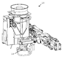
도 3은 저장부가 제거된 본 발명의 HPM의 펌프를 도시한 도면이다.
도 4는 본 발명의 HPM의 개략도이다.
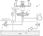
도 5는 본 발명의 HPM의 유체 회로도의 개략도이다.1 is a front view of the HPM of the present invention.
2 is a rear view of the HPM of the present invention.
Figure 3 shows the pump of the HPM of the present invention with the reservoir removed.
4 is a schematic diagram of the HPM of the present invention.
5 is a schematic diagram of a fluid circuit diagram of the HPM of the present invention.
본 발명의 유압력 모듈(10)은, 1) 유압유를 정확한 영역으로 전달하는 유압 매니폴드(12), 2) 유압유(16)가 들어있는 유압 저장부(14), 3) 유압 펌프(18), 4) DC 서보 모터(20), 5) 방향 밸브(22), 6) 냉각 시스템(24), 7) 일체형 필터 하우징(26) 및 8) 전자 장치들 - DC 서보 모터(20)를 제어하는 모터 제어부(28)로 구성된다.The
유압력 모듈(HPM)(10)은 유압유(16)를 공급하여 유압 실린더(들)(30)의 다양한 구성부를 작동시키도록 동작한다. DC 서보 모터(20)는 유압 매니폴드(12)를 통하여 유압 펌프(18)에 직접 연결된다. 모터(20)가 회전할 시에, 펌프(18)는 유압유(16)가 매니폴드(12)를 향하여 방향 밸브(22)로 전달되도록 한다. HPM(10)은 유압 실린더(30)의 양 측면으로 흐름을 전환시키도록 방향 밸브(22)에게 신호를 전송한다. The hydraulic force module (HPM) 10 operates to supply hydraulic oil 16 to actuate various components of the hydraulic cylinder (s) 30. The
센서(32)(예: 유체 라인의 유량계, 유압 실린더에 결합된 선형 트랜스듀서(34) 등)와 함께, HPM(10)은 유압 실린더(30)의 피스톤 속도를 정확하게 제어하는 비율로 유압유(16)를 제공한다. HPM은 또한 유압 실린더(30)의 피스톤의 위치가 대향력(opposing force)에 대해 이동이 없도록 유지시킬 수 있다. 이는 정확한 유량 또는 일정한 동압 및 정압을 생성한다.With sensors 32 (eg, flow meters in fluid lines,
다양한 변화 및 변형이 다음의 청구항에 의해 정의된 바와 같이 본 발명의 권리 범위 및 기술 사상을 벗어남 없이 유압력 모듈로 구현될 수 있다는 것을 고려해볼 수 있다.It is contemplated that various changes and modifications may be implemented in the hydraulic force module without departing from the scope and spirit of the present invention as defined by the following claims.
Claims (3)
상기 유압 실린더는:
유압유를 전달하는 유압 매니폴드;
유압유가 들어있는 유압 저장부;
유압 펌프;
DC 서보 모터;
방향 밸브;
냉각 시스템; 및
상기 DC 서보 모터를 제어하는 모터 제어부를 포함하는 것을 특징으로 하는 유압력 모듈.A hydraulic power module for controlling at least one hydraulic cylinder,
The hydraulic cylinder is:
A hydraulic manifold for delivering hydraulic oil;
A hydraulic reservoir containing hydraulic oil;
Hydraulic pump;
DC servo motor;
Directional valve;
Cooling system; And
Hydraulic power module comprising a motor control unit for controlling the DC servo motor.
상기 유압력 모듈은 일체형 필터 하우징을 더 포함하는 것을 특징으로 하는 유압력 모듈.The method of claim 1,
The hydraulic force module further comprises an integrated filter housing.
상기 모터 제어부는, 모터의 회전이 없고 흐름이 없는 조건 하에서, 압력을 유지시킬 수 있는 것을 특징으로 하는 유압력 모듈.The method of claim 1,
The motor control unit, the hydraulic force module, characterized in that to maintain the pressure under the condition that there is no rotation of the motor flow.
Applications Claiming Priority (2)
| Application Number | Priority Date | Filing Date | Title |
|---|---|---|---|
| US22929809P | 2009-07-29 | 2009-07-29 | |
| US61/229,298 | 2009-07-29 |
Publications (1)
| Publication Number | Publication Date |
|---|---|
| KR20120051722A true KR20120051722A (en) | 2012-05-22 |
Family
ID=42937653
Family Applications (1)
| Application Number | Title | Priority Date | Filing Date |
|---|---|---|---|
| KR1020127005012A KR20120051722A (en) | 2009-07-29 | 2010-07-27 | Hydraulic power module |
Country Status (11)
| Country | Link |
|---|---|
| US (1) | US20120121439A1 (en) |
| EP (1) | EP2459886A1 (en) |
| JP (1) | JP5843290B2 (en) |
| KR (1) | KR20120051722A (en) |
| CN (1) | CN102472301B (en) |
| AU (1) | AU2010276482B2 (en) |
| BR (1) | BR112012001418A2 (en) |
| IN (1) | IN2012DN01705A (en) |
| MX (1) | MX2012001217A (en) |
| RU (1) | RU2012105643A (en) |
| WO (1) | WO2011014486A1 (en) |
Cited By (1)
| Publication number | Priority date | Publication date | Assignee | Title |
|---|---|---|---|---|
| KR101532683B1 (en) * | 2013-10-29 | 2015-07-01 | 국방과학연구소 | Hydraulic system |
Families Citing this family (5)
| Publication number | Priority date | Publication date | Assignee | Title |
|---|---|---|---|---|
| US9193046B2 (en) * | 2012-08-03 | 2015-11-24 | Spx Flow, Inc. | Auto cycle pump and method of operation |
| CN107000355A (en) * | 2014-09-19 | 2017-08-01 | Siti-B&T集团股份公司 | The hydraulic system for the forcing press for being used to manufacture ceramic product is particularly for forcing press |
| CN107725506A (en) * | 2017-10-23 | 2018-02-23 | 天津世仓工业设备有限公司 | A kind of numerical control press electrohydraulic servo-controlling system |
| EP3771482A1 (en) | 2019-07-30 | 2021-02-03 | Dana Motion Systems Italia S.R.L. | Adaptor plug for a spin-on filter |
| DE202019005807U1 (en) | 2019-07-30 | 2022-03-25 | Dana Motion Systems Italia S.R.L. | Adapter plug for a twist-on filter |
Family Cites Families (19)
| Publication number | Priority date | Publication date | Assignee | Title |
|---|---|---|---|---|
| US3902318A (en) * | 1974-08-28 | 1975-09-02 | Sperry Rand Corp | Power transmission |
| US4043127A (en) * | 1975-07-02 | 1977-08-23 | Kubik Philip A | Reservoir housing |
| JPS62184206A (en) * | 1986-02-07 | 1987-08-12 | Hitachi Seiko Ltd | Electro-hydraulic convertible driving device |
| US5144801A (en) * | 1989-04-28 | 1992-09-08 | Parker Hannifin Corporation | Electro-hydraulic actuator system |
| US5778671A (en) * | 1996-09-13 | 1998-07-14 | Vickers, Inc. | Electrohydraulic system and apparatus with bidirectional electric-motor/hydraulic-pump unit |
| US6282893B1 (en) * | 1999-08-19 | 2001-09-04 | Delaware Capital Formation, Inc. | Self-contained actuator |
| CA2405739C (en) * | 2000-04-14 | 2006-12-05 | Actuant Corporation | Variable speed hydraulic pump |
| JP2001317447A (en) * | 2000-05-09 | 2001-11-16 | Tokimec Inc | Hydraulic device |
| JP2001317507A (en) * | 2000-05-11 | 2001-11-16 | Daishin Shoko:Kk | Oil tank structure in hydraulic cylinder device |
| JP2002147405A (en) * | 2000-11-14 | 2002-05-22 | Toyooki Kogyo Co Ltd | Hydraulic driver |
| JP2003172306A (en) * | 2001-12-04 | 2003-06-20 | Komatsu Ltd | Hydraulic signal output circuit |
| FR2851306B1 (en) * | 2003-02-18 | 2006-08-04 | Giat Ind Sa | COMPACT ELECTRO-HYDRAULIC GENERATOR FOR TURRET ENGINE |
| JP4439847B2 (en) * | 2003-06-24 | 2010-03-24 | 東京計器株式会社 | Hydraulic device |
| US7086225B2 (en) * | 2004-02-11 | 2006-08-08 | Haldex Hydraulics Corporation | Control valve supply for rotary hydraulic machine |
| ITRM20060085U1 (en) * | 2006-05-17 | 2007-11-18 | Findisa S R L | HYDRAULIC LOW VOLTAGE SYSTEM WITH ELECTRONIC CONTROL OF AUTOMATIC CLOSURE HANDLING |
| DE102006026077A1 (en) * | 2006-06-03 | 2007-12-06 | Hydac Process Technology Gmbh | fluid system |
| US7420350B2 (en) * | 2006-11-17 | 2008-09-02 | Gm Global Technology Operations, Inc. | Methods and apparatus for an active front steering actuator |
| CN101042149A (en) * | 2007-04-20 | 2007-09-26 | 绍兴市肯特机械电子有限公司 | Hydraulic power system controlled by servo electric machine |
| CN101382157A (en) * | 2007-09-07 | 2009-03-11 | 中国科学院沈阳自动化研究所 | Electrohydraulic mixed power cylinder |
-
2010
- 2010-07-27 KR KR1020127005012A patent/KR20120051722A/en active IP Right Grant
- 2010-07-27 BR BR112012001418A patent/BR112012001418A2/en not_active IP Right Cessation
- 2010-07-27 RU RU2012105643/06A patent/RU2012105643A/en not_active Application Discontinuation
- 2010-07-27 IN IN1705DEN2012 patent/IN2012DN01705A/en unknown
- 2010-07-27 EP EP10740086A patent/EP2459886A1/en not_active Withdrawn
- 2010-07-27 MX MX2012001217A patent/MX2012001217A/en active IP Right Grant
- 2010-07-27 AU AU2010276482A patent/AU2010276482B2/en not_active Ceased
- 2010-07-27 US US13/386,962 patent/US20120121439A1/en not_active Abandoned
- 2010-07-27 JP JP2012522954A patent/JP5843290B2/en not_active Expired - Fee Related
- 2010-07-27 WO PCT/US2010/043338 patent/WO2011014486A1/en active Application Filing
- 2010-07-27 CN CN201080033083.4A patent/CN102472301B/en not_active Expired - Fee Related
Cited By (1)
| Publication number | Priority date | Publication date | Assignee | Title |
|---|---|---|---|---|
| KR101532683B1 (en) * | 2013-10-29 | 2015-07-01 | 국방과학연구소 | Hydraulic system |
Also Published As
| Publication number | Publication date |
|---|---|
| JP2013501196A (en) | 2013-01-10 |
| CN102472301A (en) | 2012-05-23 |
| BR112012001418A2 (en) | 2019-09-24 |
| CN102472301B (en) | 2015-12-16 |
| JP5843290B2 (en) | 2016-01-13 |
| AU2010276482A1 (en) | 2012-02-02 |
| RU2012105643A (en) | 2013-09-10 |
| MX2012001217A (en) | 2012-04-30 |
| IN2012DN01705A (en) | 2015-06-05 |
| EP2459886A1 (en) | 2012-06-06 |
| AU2010276482B2 (en) | 2015-07-09 |
| WO2011014486A1 (en) | 2011-02-03 |
| US20120121439A1 (en) | 2012-05-17 |
Similar Documents
| Publication | Publication Date | Title |
|---|---|---|
| US8453441B2 (en) | System and method for pump-controlled cylinder cushioning | |
| JP4365870B2 (en) | Fluid pressure actuator | |
| KR20120051722A (en) | Hydraulic power module | |
| JP5599504B2 (en) | Hydraulic fan drive | |
| CN101392809B (en) | Active hydraulic damper and hydraulic actuator | |
| US6854269B2 (en) | Noise attenuation in a hydraulic circuit | |
| US9233695B2 (en) | Railcar damping device | |
| US9677579B2 (en) | Actuator unit | |
| JP2006336805A (en) | Control device of work machine | |
| US8429907B2 (en) | Active hydraulic regeneration for motion control | |
| CN105971051B (en) | Digging machine | |
| JP5954927B2 (en) | Hydraulic device | |
| JP2011038558A (en) | Electric fluid pressure actuator device | |
| JP6009770B2 (en) | Hydraulic closed circuit system | |
| KR20230054726A (en) | Hydraulic Active Suspension Flow Control System | |
| CN116838660B (en) | Hydraulic control system for realizing self-feedback of main pump and oil supplementing synchronous variable | |
| CN220769824U (en) | Hydraulic system | |
| CN106523480A (en) | Hydraulic servo drive system and control method | |
| JP2013160319A (en) | Hydraulic closed circuit system | |
| JP5391119B2 (en) | Actuator unit | |
| JP2015096757A (en) | Hydraulic drive unit | |
| JP2002206507A (en) | Actuator device |
Legal Events
| Date | Code | Title | Description |
|---|---|---|---|
| A201 | Request for examination | ||
| E902 | Notification of reason for refusal | ||
| E902 | Notification of reason for refusal | ||
| E701 | Decision to grant or registration of patent right |