KR20120042653A - Hot water supplying equipment - Google Patents
Hot water supplying equipment Download PDFInfo
- Publication number
- KR20120042653A KR20120042653A KR1020110103083A KR20110103083A KR20120042653A KR 20120042653 A KR20120042653 A KR 20120042653A KR 1020110103083 A KR1020110103083 A KR 1020110103083A KR 20110103083 A KR20110103083 A KR 20110103083A KR 20120042653 A KR20120042653 A KR 20120042653A
- Authority
- KR
- South Korea
- Prior art keywords
- hot water
- silver ion
- ion generator
- silver
- water supply
- Prior art date
Links
Images


Classifications
-
- F—MECHANICAL ENGINEERING; LIGHTING; HEATING; WEAPONS; BLASTING
- F24—HEATING; RANGES; VENTILATING
- F24D—DOMESTIC- OR SPACE-HEATING SYSTEMS, e.g. CENTRAL HEATING SYSTEMS; DOMESTIC HOT-WATER SUPPLY SYSTEMS; ELEMENTS OR COMPONENTS THEREFOR
- F24D17/00—Domestic hot-water supply systems
-
- C—CHEMISTRY; METALLURGY
- C02—TREATMENT OF WATER, WASTE WATER, SEWAGE, OR SLUDGE
- C02F—TREATMENT OF WATER, WASTE WATER, SEWAGE, OR SLUDGE
- C02F1/00—Treatment of water, waste water, or sewage
- C02F1/42—Treatment of water, waste water, or sewage by ion-exchange
-
- F—MECHANICAL ENGINEERING; LIGHTING; HEATING; WEAPONS; BLASTING
- F24—HEATING; RANGES; VENTILATING
- F24D—DOMESTIC- OR SPACE-HEATING SYSTEMS, e.g. CENTRAL HEATING SYSTEMS; DOMESTIC HOT-WATER SUPPLY SYSTEMS; ELEMENTS OR COMPONENTS THEREFOR
- F24D19/00—Details
- F24D19/10—Arrangement or mounting of control or safety devices
- F24D19/1006—Arrangement or mounting of control or safety devices for water heating systems
- F24D19/1051—Arrangement or mounting of control or safety devices for water heating systems for domestic hot water
-
- F—MECHANICAL ENGINEERING; LIGHTING; HEATING; WEAPONS; BLASTING
- F24—HEATING; RANGES; VENTILATING
- F24D—DOMESTIC- OR SPACE-HEATING SYSTEMS, e.g. CENTRAL HEATING SYSTEMS; DOMESTIC HOT-WATER SUPPLY SYSTEMS; ELEMENTS OR COMPONENTS THEREFOR
- F24D2220/00—Components of central heating installations excluding heat sources
- F24D2220/04—Sensors
- F24D2220/044—Flow sensors
Abstract
Description
본 발명은 온수 공급 장치에 관한 것이다.The present invention relates to a hot water supply device.
온수를 사용 장소로 공급하는 온수공급장치로서, 온수저장탱크를 구비하고 상기 온수저장탱크 내의 온수를 사용 장소인 욕조로 공급하며, 또한 급탕관(給湯管)에 은 이온 발생기를 설치한 온수공급장치가 알려져 있다.A hot water supply device for supplying hot water to a place of use, comprising a hot water storage tank, supplying hot water in the hot water storage tank to a bath, a hot water supply device, and a silver ion generator installed in a hot water supply pipe. Is known.
은 이온 발생기는 급탕관 내에서 서로 대향하는 한 쌍의 은제의 전극을 구비하고, 이들 전극의 상호간에 전압이 인가됨으로써 양 전극간에 온수를 통하여 전류가 흐르고, 이에 수반하여 한쪽의 은 전극으로부터 다른 쪽의 은 전극으로 이동하는 은 이온을 발생시킨다.The silver ion generator includes a pair of silver electrodes facing each other in a hot water supply pipe, and a current flows through the hot water between the two electrodes by applying a voltage between these electrodes, thereby causing the current to flow from one silver electrode to the other. Generates silver ions moving to the silver electrode.
상기 은 이온이 온수와 함께 욕조로 공급된다. 상기 은 이온은 높은 항균력을 발휘한다. 또한, 온수에 포함되는 은 이온의 농도에 따라 항균력이 다르다. The silver ions are supplied to the bath with hot water. The silver ion exhibits high antibacterial activity. In addition, the antibacterial activity varies depending on the concentration of silver ions contained in the warm water.
일반적으로 은 이온 발생기를 구비한 온수공급장치는 목욕물 받기 후의 온수에 포함되는 은 이온의 농도가 어느 일정한 농도가 되도록 은 이온 발생기를 제어하는 제어수단을 구비하고 있다.In general, a hot water supply device having a silver ion generator is provided with a control means for controlling the silver ion generator so that the concentration of the silver ions contained in the hot water after receiving the bath water becomes a certain concentration.
여기에서, 온수에 포함되는 은 이온의 농도가 높으면 높을수록, 온수의 항균력은 높은 것으로 알려져 있고, 일반적인 온수공급장치의 제어수단은 온수가 높은 항균력을 발휘하는 은 이온 농도가 되도록 은 이온 발생기를 제어하도록 설정되어 있다.Here, the higher the concentration of silver ions contained in the hot water, the higher the antibacterial activity of the hot water is, and the control means of a general hot water supply device controls the silver ion generator so that the hot water has a high concentration of silver ions exhibiting high antibacterial activity. It is set to.
그러나, 높은 항균력을 발휘하는 은 이온 농도로 하는 경우, 은 이온 발생기의 은 이온 발생원의 소모가 심하고, 사용자가 그만큼 높은 은 이온 농도를 필요로 하지 않는 경우에도 은 이온 발생원이 소모된다. 이에 의해, 사용자는 은 이온 발생기의 은 이온 발생원을 빈번하게 교환하게 되어 불필요한 교환비용이 필요해진다.However, when the silver ion concentration exhibiting high antimicrobial power is used, the silver ion source of the silver ion generator is consumed severely, and the silver ion source is consumed even when the user does not need the high silver ion concentration. As a result, the user frequently exchanges the silver ion generating source of the silver ion generator, so that an unnecessary exchange cost is required.
본 발명의 실시형태는 상기 사정을 고려한 것으로, 그 목적은 사용자가 최적의 은 이온 농도의 온수를 선택적으로 이용할 수 있는 온수공급장치를 제공하는 것이다. Embodiment of this invention considered the said situation, The objective is to provide the hot water supply apparatus which a user can selectively use the hot water of optimal silver ion concentration.
본 발명의 실시형태의 온수공급장치에서는 온수의 공급로에 설치된 은제의 전극을 구비하고, 온수의 공급시에 동작하여 온수 중에 은 이온을 발생시키는 은 이온 발생기와, 소정량의 온수에 포함되는 은 이온의 농도를 설정하는 설정수단과, 설정수단으로 설정된 은 이온의 농도에 기초하여 은 이온 발생기의 동작을 제어하는 제어수단을 갖는다.The hot water supply device according to the embodiment of the present invention includes a silver ion generator provided with a silver electrode provided in a hot water supply path, which is operated at the time of supply of hot water to generate silver ions in the hot water, and a silver contained in a predetermined amount of hot water. Setting means for setting the concentration of the ions, and control means for controlling the operation of the silver ion generator based on the concentration of the silver ions set by the setting means.
이에 의해, 은 이온 발생기의 동작시간을 변경함으로써 온수의 은 이온 농도를 임의로 설정할 수 있는 온수공급장치를 제공할 수 있다. Thereby, the hot water supply device which can arbitrarily set the silver ion concentration of hot water by changing the operation time of a silver ion generator can be provided.
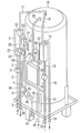
도 1은 본 발명의 실시형태에 관한 온수공급장치의 구성을 도시한 도면이다.
도 2는 본 발명의 실시형태에 관한 온수공급장치의 저장탱크 및 그 주변부의 구성을 도시한 사시도이다.
도 3은 본 발명의 실시형태에 관한 온수공급장치의 제어부의 주요부를 도시한 블럭도이다.
도 4는 본 발명의 제 2 실시형태에 관한 은 이온 농도가 0.05ppm으로 설정된 경우의 은 이온 발생기의 동작시간을 도시한 도면이다.
도 5는 본 발명의 제 2 실시형태에 관한 온수공급장치의 작용을 설명하는 플로우차트이다.
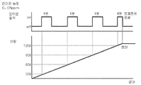
도 6은 본 발명의 제 2 실시형태에 관한 은 이온 농도가 0.05ppm으로 설정된 경우의 은 이온 발생기의 그 밖의 동작시간을 도시한 도면이다.
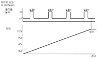
도 7은 본 발명의 제 2 실시형태에 관한 은 이온 농도가 0.025ppm으로 설정된 경우의 은 이온 발생기의 동작시간을 도시한 도면이다.
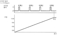
도 8은 본 발명의 제 2 실시형태에 관한 은 이온 농도가 0.0125ppm으로 설정된 경우의 은 이온 발생기의 동작시간을 도시한 도면이다.
도 9는 본 발명의 실시형태에 관한 온수공급장치를 조작하는 조작기의 표시부의 표시예를 도시한 도면이다.1 is a diagram showing the configuration of a hot water supply device according to an embodiment of the present invention.
2 is a perspective view showing the configuration of a storage tank and a peripheral portion of the hot water supply device according to the embodiment of the present invention.
3 is a block diagram showing a main part of a control unit of a hot water supply device according to an embodiment of the present invention.
4 is a diagram showing an operating time of a silver ion generator when the silver ion concentration according to the second embodiment of the present invention is set to 0.05 ppm.
5 is a flowchart for explaining the operation of the hot water supply device according to the second embodiment of the present invention.
Fig. 6 is a diagram showing other operating time of the silver ion generator when the silver ion concentration according to the second embodiment of the present invention is set to 0.05 ppm.
Fig. 7 is a diagram showing the operating time of the silver ion generator when the silver ion concentration according to the second embodiment of the present invention is set to 0.025 ppm.
FIG. 8 is a diagram showing an operating time of a silver ion generator when the silver ion concentration according to the second embodiment of the present invention is set to 0.0125 ppm.
9 is a diagram showing a display example of a display portion of an manipulator for operating a hot water supply device according to an embodiment of the present invention.
이하, 본 발명의 실시형태에 대해서 도면을 참조하면서 설명한다.DESCRIPTION OF THE PREFERRED EMBODIMENTS Hereinafter, embodiments of the present invention will be described with reference to the drawings.
도 1에서 "1"은 급탕 유닛으로, 급수관(2)을 통하여 급수원(도시하지 않음)에 접속된다. 상기 급수관(2)의 물이 급수관(2)상의 감압밸브(3)에서 감압되어 급수관(4)에 인도되고, 급수관(4)의 물이 역류방지밸브(5)를 통하여 저장 탱크(10)의 하부에 인도된다. 또한, 감압밸브(3)에서 감압된 물의 일부가 급수관(6) 및 급수관(6)상의 역류방지밸브(7)를 통하여 혼합수전(12)에 인도된다.In FIG. 1, "1" is a hot water supply unit, and is connected to a water supply source (not shown) through the
온수저장탱크(10)의 상부에 급탕관(11)을 통하여 혼합수전(12)이 접속되고, 혼합수전(12)의 출구가 급탕관(온수의 공급로)(13), 급탕관(13)상의 호퍼(14), 은 이온 발생기(50), 및 유량을 계측하는 유량계측수단인 유량계(30)를 통하여 욕조(20)에 접속된다.The mixing
유량계(30)는 급탕관(13) 및 은 이온 발생기(50)를 통과하는 온수의 유량을 계측하기 위한 유량계측수단이다.The
급탕관(13)에서의 은 이온 발생기(50)의 설치 부분보다 하류측 위치에, 온수관(15) 및 온수관(15)상의 순환펌프(16)를 통하여 욕조열교환기(17)의 제 1 유로의 입구가 접속되고, 제 1 유로의 출구가 온수관(18)을 통하여 욕조(20)에 접속된다.The first of the
즉, 욕조(20)에 연결되는 급탕관(13)의 일부, 온수관(15), 순환펌프(16), 욕조열교환기(17)의 제 1 유로, 및 온수관(18)에 의해 욕조(20) 내의 온수를 보온(다시 데우기라고도 함)하기 위한 보온유로가 형성된다.That is, a portion of the
급탕관(11)에 온수관(31) 및 온수관(31)상의 역류방지밸브(32)를 통하여 욕조열교환기(17)의 제 2 유로의 입구가 접속되고, 제 2 유로의 출구가 온수관(33) 및 온수관(33)상의 순환펌프(34)를 통하여 온수저장탱크(10)의 상부에 접속된다.An inlet of the second flow path of the
급탕관(11)에 급탕관(35) 및 급탕관(35)상의 역류방지밸브(36)를 통하여 혼합수전(37)이 접속되고, 혼합수전(37)의 출구가 급탕관(38)을 통하여 사용 장소인 부엌, 세면대, 욕실의 샤워기 등에 분기 접속된다. 혼합수전(37)에는 급수관(2)에서의 감압 밸브(3)를 거친 물이 인도되어 있고, 그 물이 급탕관(35)으로부터의 온수에 혼합된다.The mixing
온수저장탱크(10)의 하부에 온수관(41) 및 온수관(41) 상의 순환펌프(42)를 통하여 열원 유닛(80)의 수(水)열교환기(82)의 입구가 접속되고, 수열교환기(82)의 출구가 온수관(43)을 통하여 온수관(33)에서의 순환펌프(34)의 하류측 위치에 접속된다.An inlet of the
호퍼(14)는 개폐밸브(14a, 14b), 역류방지밸브(14c, 14e) 및 플로우센서(흐름검지수단)(14d)를 구비한다. 플로우센서(흐름검지수단)(14d)은 급탕관(13)에서의 온수의 흐름을 검지한다.The
열원유닛(80)은 도 1의 파선 화살표로 도시한 바와 같이 압축기(81)로부터 토출되는 냉매를 수열교환기(82), 팽창밸브(83), 및 공기열교환기(84)를 통하여 압축기(81)에 되돌리는 히트펌프식 냉동 사이클을 구비하고 또한 열원 유닛 제어부(90)를 구비하며, 외기로부터 열을 받아들이고(열교환시켜 열을 흡수하는 것), 그 받아들인 열을 수열교환기(82)의 온수(온수관(41)으로부터 인도되는 온수)에 준다.The
또한, 급탕 유닛(1)에 급탕 유닛 제어부(60)가 설치되고, 상기 급탕 유닛 제어부(60)에 리모트컨트롤식의 조작기(이하, 리모컨이라고 함)(70) 및 열원 유닛(80)의 열원 유닛 제어부(90)가 접속된다.In addition, a hot water supply
리모컨(70)은 욕조(20)의 근방에 설치되고, 급탕 유닛(1) 및 열원 유닛(80)에 대한 운전 조건을 설정할 수 있다. 또한, 리모컨(70)에는 도 3에 도시한 바와 같이 액정표시부(71)와, 사용자가 은 이온 농도를 설정하기 위한 설정수단으로서 조작부(72)가 설치되어 있다.The
온수 저장 탱크(10) 및 그 주변부의 구성을 도 2에 도시한다. 급탕 유닛 제어부(60)는 온수 저장 탱크(10)의 측면부에 부착되어 있다.The structure of the hot
급탕 유닛 제어부(60)의 주요부를 도 3에 도시한다.The main part of the hot water supply
급탕 유닛 제어부(60)는 상용교류전원 AC에 접속된 전원단자(61), 상기 전원단자(61)에 통전로(62) 및 상기 통전로(62) 상의 릴레이 접점(65a)을 통하여 접속된 구동회로(63), 주제어부(64), 상기 주제어부(64)에 접속된 릴레이(65), 주제어부(64)에 접속된 타이머(66)를 갖는다. 그리고, 주제어부(64)에 리모컨(70) 및 열원 유닛 제어부(90)가 접속된다. 구동회로(63)에는 은 이온 발생기(50)가 접속되어 있다.The hot water supply
구동회로(63)는 은 이온 발생기(50)를 구동한다. 은 이온 발생기(50)는 급탕관(13) 내에 배치된 서로 대향하는 한쌍의 은제의 전극(51, 52)를 갖고, 이들 전극(51, 52)의 상호간에 구동회로(63)로부터 전압을 인가함으로써 동작하여 양전극(51,52) 간에 온수를 통하여 전류를 흐르게 하고, 이에 수반하여 한쪽의 은전극(51)으로부터 다른쪽 은전극(52)으로 이동하려고 하는 은(Ag) 이온을 발생시킨다.The
상기 은 이온이 급탕관(13) 내의 온수와 함께 욕조(20)로 공급된다. 또한, 급탕관(13)에서 은 이온 발생기(50)의 설치 위치로부터 적어도 온수관(15)의 접속부위까지의 구간에는 누전방지를 위해 절연 처리가 실시된, 예를 들어 알루미늄 3층관이 사용된다.The silver ions are supplied to the
주제어부(64)는 주요한 기능으로서 다음의 (1) 내지 (7)의 수단을 갖는다.The
(1) 미리 정해져 있는 시간대, 예를 들어 심야전력시간대에 열원 유닛(80)의 열원 유닛 제어부(90)에 운전 온을 지령하고, 또한 순환펌프(42)를 운전(온)하는 제어수단.(1) Control means for instructing the heat source
(2) 욕조(20)로의 급탕(목욕물 받기?온수보충을 포함)이 리모컨(70)의조작에 의해 지시되면 호퍼(14)의 개폐 밸브(14a, 14b)를 개방하는 개방제어수단.(2) Open control means for opening /
(3) 은 이온 발생기(50)의 동작시간(T)을 타이머(66)에 의해 계시(計時)하는 계시수단.(3) means for counting the operating time T of the
(4) 조작부(72)가 조작되어 은 이온 농도가 설정되고, 설정된 목욕물 받기량(La)에 대해서 설정된 은 이온의 농도에 기초하여 은 이온 발생기 동작시간(Ts)을 설정(제어)하는 설정제어수단.(4) A setting control for operating the
(5) 목욕물 받기 운전을 개시한 직후에 릴레이(65)를 작동시켜 상기 릴레이 접점(65a)을 폐쇄하고, 이에 의해 은 이온 발생기(50)에 통전하여 은 이온 발생기(50)를 동작시키고, 설정된 은 이온 농도에 따른 은 이온 발생기 총동작시간(Ta)을 초과하면 릴레이(65)를 해제하여 그 릴레이 접점(65a)을 개방하고, 이에 의해 은 이온 발생기(50)로의 통전을 차단하여 은 이온 발생기(50)의 동작을 정지시키는 통전제어수단.(5) Immediately after the bath receiving operation is started, the
(6) 유량계(30)를 통과한 온수의 운전개시로부터의 적산유량(L)을 검지(적산)하고 적산유량(L)이 설정된 목욕물 받기량(La)에 도달하면 호퍼(14)의 개폐 밸브(14a, 14b)를 폐쇄하는 폐쇄제어수단.(6) The open / close valve of the
(7) 조작부(72)의 조작으로 설정되는 은 이온 농도와, 그 은 이온 농도에 의한 효능 및 주의 사항을 리모컨(70)의 액정표시부(71)에 표시하여 알리는 알림수단.(7) Notification means for displaying on the liquid
다음에, 은 이온 발생기(50)의 작용에 대해서 설명한다.Next, the operation of the
본 실시형태의 은 이온 발생기(50)는 약 30 l의 온수에 대해서 1 분간 동작하면 은 이온 농도가 0.05 ppm이 되도록 전류값이 설정되어 있다. 또한, 전류값에 의해 동작시간(T)과 은 이온 농도의 관계는 변화된다.The
표 1에 욕조(20)의 목욕물 받기량에 대한 은 이온 발생기(50)의 총동작 시간(Ta)과 은 이온 농도의 관계를 나타낸다.Table 1 shows the relationship between the total operating time Ta of the

사용자가 리모컨(70)에 설치된 조작부(72)를 조작함으로써 표 1에 나타낸 바와 같이 은 이온 발생기(50)의 동작시간이 설정된다. 온수의 은 이온 농도는 0.05 ppm, 0.025 ppm, 0.0125 ppm의 3단계로 설정할 수 있다.As the user manipulates the
여기에서 표 1에 표시되는 은 이온 발생기(50)의 동작시간은 설정된 목욕물 받기량에 대한 총동작 시간(Ta)이다. 예를 들어, 목욕물 받기량이 130 l인 경우, 은 이온 발생기(50)의 총동작 시간(Ta)을 4 분간으로 하면 은 이온 농도가 0.05 ppm의 온수가 되고, 총동작 시간(Ta)을 2 분간으로 하면 은 이온 농도가 0.025 ppm이 되며, 총동작 시간(Ta)을 1 분간으로 하면 은 이온 농도는 0.0125 ppm이 된다.Here, the operating time of the
표 1의 은 이온 농도의 온수를 얻기 위한 목욕물 받기 운전에 대해서 설명한다.The bath receiving operation for obtaining hot water of silver ion concentration of Table 1 is demonstrated.
심야 전력 시간대에서 열원 유닛(80)의 압축기(81)가 운전(온)하고, 압축기(81)로부터 토출되는 냉매가 수열교환기(82), 팽창 밸브(83), 공기열 교환기(84)를 통과하여 순환된다.In the late-night power time zone, the
이에 수반하여, 순환 펌프(42)가 운전(온)하고, 온수 저장 탱크(10)의 하부의 온수가 온수관(41)을 통과하여 수열교환기(82)에 유입되어 가열된다. 수열교환기(82)로부터 유출되는 온수는 온수관(43) 및 온수관(33)을 통과하여 온수 저장 탱크(10)의 상부에 공급된다. 이렇게 하여, 온수 저장 탱크(10)에 온수가 저장된다.In connection with this, the
그리고, 리모컨(70)의 조작에 의해 목욕물 받기 운전이 개시되면, 호퍼(14)의 개폐 밸브(14a, 14b)가 개방되고, 온수 저장 탱크(10) 내의 온수가 급탕관(11), 혼합수전(12), 급탕관(13) 및 은 이온 발생기(50)를 통과하여 욕조(20)에 공급되어 목욕물 받기 운전이 이루어진다.When the bath water receiving operation is started by the operation of the
여기에서, 은 이온 발생기(50)를, 목욕물 받기 운전 개시시부터 설정된 목욕물 받기량(La)에 대한 은 이온 발생기 총동작 시간(Ta)의 기간만큼 작동시키고, 그 후 은 이온 발생기(50)를 정지시켜 목욕물 받기 운전이 계속된다. 그리고, 적산유량(L)이 설정된 목욕물 받기량(La)에 도달할 때까지 목욕물 받기를 실시한다.Here, the
이에 의해, 목욕물 받기 운전 종료후에는 욕조(20) 내에 설정된 은 이온 농도의 온수가 받아진다.Thereby, after completion of the bath water receiving operation, hot water having a silver ion concentration set in the
이와 같이, 은 이온 발생기(50)에 통전되는 전류값을 변경하지 않고 은 이온 발생기(50)의 동작시간을 변경함으로써 욕조(20) 내의 온수의 은 이온 농도를 임의로 설정할 수 있다.In this way, the silver ion concentration of the hot water in the
다음에, 제 2 실시형태에 대해서 도 4 내지 도 8을 사용하여 설명한다.Next, 2nd Embodiment is described using FIGS. 4-8.
제 2 실시형태에서 도 1 내지 도 3에 도시한 구성은 제 1 실시형태와 동일하다. 주제어부(64)는 제 1 목욕물 받기 형태와 동일한 기능 (1) 내지 (4), (6), (7)의 수단을 갖고 있고, 통전제어수단(5) 대신 이하의 (5A)의 통전제어수단을 구비하고 있다.1 to 3 in the second embodiment is the same as the first embodiment. The
(5A) 유량계측수단인 유량계(30)에 의해 온수의 적산유량(L)이 소정량에 도달한 것을 검지할 때마다, 릴레이(65)를 작동하여 그 릴레이 접점(65a)을 폐쇄하고, 이에 의해 은 이온 발생기(50)에 통전하여 은 이온 발생기(50)를 동작시킨다.(5A) Whenever the
그리고, 목욕물 받기량에 따른 은 이온 발생기의 동작시간(Ts)을 초과하면, 릴레이(65)를 해제하여 릴레이 접점(65a)을 개방하고, 이에 의해 은 이온 발생기(50)로의 통전을 차단하여 은 이온 발생기(50)의 동작을 정지시키는 것을 반복하는 통전제어수단.When the operation time Ts of the silver ion generator according to the amount of bath water is exceeded, the
여기에서 구체적으로는 동작시간(Ts)은 목욕물 받기량 30 l 급탕할 때마다 은 이온 발생기(50)를 동작시키는 시간이고, 욕조(20) 내에 설정된 목욕물 받기량(La)의 온수가 저류되는 기간내에, 은 이온 발생기(50)가 동작시간(Ts)으로 반복하여 동작하고, 전체로서의 은 이온 발생기(50)의 동작시간이 총작동시간(Ta)과 거의 일치하는 것이다.Specifically, the operating time Ts is a time for operating the
예를 들어 목욕물 받기량 130 l의 경우, 도 4와 도 6 내지 도 8의 그래프로 나타낸 바와 같이 된다. 즉, 도 4에 도시한 바와 같이 농도 0.05 ppm의 경우에는 은 이온 발생기(50)의 동작시간(Ts)을 1 분간으로 하고 30 l 급탕될 때마다 은 이온 발생기(50)를 1 분간 동작시키고, 130 l가 급탕될 때까지의 동안에 총동작시간(Ta)인 4 분 정도가 된다.For example, in the case of 130 L of bath water receiving amount, it becomes as shown with the graph of FIG. 4 and FIG. That is, as shown in FIG. 4, when the concentration is 0.05 ppm, the operating time Ts of the
예를 들어, 도 5의 플로우차트에 의해 리모컨(70)의 조작에 의해 목욕물 받기량이 130 l, 설정된 은 이온 농도가 0.05ppm인 경우의 동작을 설명한다.For example, the operation | movement when the amount of bath water receiving 130l and the set silver ion concentration is 0.05 ppm by operation of the
욕조(20)로의 급탕(목욕물 받기)이 리모컨(70)의 조작에 의해 지시되면, n=1이 설정되고(단계 101), 호퍼(14)의 개폐 밸브(14a, 14b)가 개방되며, 온수 저장 탱크(10) 내의 온수가 급탕관(11), 혼합수전(12), 급탕관(13), 및 은 이온 발생기(50)를 통과하여 욕조(20)에 공급된다. 이 때, 온수의 흐름이 플로우센서(14d)에서 검지되고, 유량계(30)를 통과한 온수의 적산유량(L)의 계측을 개시한다(단계 102).When the hot water supply (receiving the bath water) to the
다음에, 적산유량(L)이 30 l×n에 도달했는지의 여부를 판정한다(단계 103). 여기에서 첫회는 n=1이므로 단계 103은 30 l에 도달했는지의 여부의 판정이 되고, 이후 n의 값의 증가에 따라서 적산유량(L)의 판정값이 변화된다.Next, it is determined whether or not the integrated flow rate L has reached 30 l x n (step 103). Here, since the first time is n = 1,
적산유량(L)이 30 l×n에 도달하면(단계 103의 '예'), 30 l×n에 도달했다고 판정된 적산유량(L)이, 목표의 목욕물 받기량 130 l(La)를 초과하고 있는지의 여부를 판정하고(단계 104), 초과하지 않은 경우에는(단계 104의 '아니오'), 은 이온 발생기(50)의 동작을 개시한다(단계 106). 즉, 릴레이(65)가 작동하여 릴레이 접점(65a)이 폐쇄되고, 이 폐쇄에 의해 구동회로(63)가 동작하여 은 이온 발생기(50)가 동작된다.If the accumulated flow rate L reaches 30 l × n (YES in step 103), the accumulated flow rate L determined to have reached 30 l × n exceeds the target bath water receiving amount 130 l (La). It is judged whether or not (step 104), and if not exceeded (NO in step 104), the operation of the
또한, 은 이온 발생기(50)의 동작과 동시에 계시수단인 타이머(66)가 은 이온 발생기의 동작시간(Ts)의 계시를 개시한다(단계 106).At the same time as the operation of the
단계 107에서 은 이온 발생기(50)의 동작시간(Ts)이 1분(Tsa)을 경과했는지의 여부를 판정한다.In
동작시간(Ts)이 1분 미만인 경우에는(단계 107의 '아니오'), 단계 104로 되돌아가 은 이온 발생기(50)의 동작을 계속한다.If the operating time Ts is less than 1 minute (NO in step 107), the process returns to step 104 where the operation of the
동작시간(Ts)이 소정 시간인 1분(Tsa)을 경과하면(단계 107의 '예'), 은 이온 발생기의 동작을 정지시킨다(단계 108). 즉, 릴레이(65)가 해제되어 릴레이 접점(65a)이 개방된다. 상기 개방에 의해 구동회로(63) 및 은 이온 발생기(50)의 동작이 정지된다.When the operating time Ts passes one minute Tsa, which is a predetermined time (YES in step 107), the operation of the silver ion generator is stopped (step 108). That is, the
그 후, n=n+1이 설정되고(단계 109), 단계 103으로 되돌아가, 적산유량(L)이 다음의 값(n+1)의 처리로 이행된다. 즉, 적산유량(L)이 60 l(30 l×2)에 도달하고(단계 103의 '예'), 적산유량(L)이 설정된 목욕물 받기량 130 l(La)을 초과하지 않은 경우(단계 104의 '아니오'), 은 이온 발생기(50)를 다시 동작시켜 타이머(66)에 의해 은 이온 발생기(50)의 동작시간(Ts)의 계측을 다시 개시한다(단계 106).Thereafter, n = n + 1 is set (step 109), the flow returns to step 103, and the integration flow rate L proceeds to the processing of the next
동작 시간(Ts)이 추가로 1 분(Tsa) 경과할 때까지 적산유량(L)이 130 l(La)에 도달하지 않은 것을 확인하면서(단계 104의 '아니오') 은 이온 발생기(50)를 계속 동작시킨다(단계 107의 '아니오'). 그리고, 동작시간(Ts)이 1분(Tsa)을 초과하면(단계 107의 '예'), 타이머(66)에 의한 계시를 종료하고, 은 이온 발생기(50)의 동작을 종료한다(단계 108). 그리고, 적산유량(L)이 또한 다음의 값(n=n+1)의 처리로 이행한다(단계 109).While confirming that the accumulated flow rate L has not reached 130 l (La) until the operating time Ts is further 1 minute (Tsa) (NO in step 104), the
상기의 처리가 적산유량(L)이 설정된 목욕물 받기량 130 l(La)에 도달할 때까지 반복된다.The above process is repeated until the integrated flow rate L reaches the set bath water receiving amount 130 l (La).
유량계(30)의 계측에 의해 적산유량(L)이 설정된 목욕물 받기량 130 l(La)에 도달하면(단계 104의 '예'), 호퍼(14)의 개폐 밸브(14a, 14b)가 폐쇄되어 욕조(20)로의 급탕이 정지된다(단계 105). 또한, 도 6의 그래프에 나타낸 바와 같이 은 이온 발생기의 동작 시간(T)이 목표에 도달하지 않아도 은 이온 발생기(50)의 동작이 정지된다.When the accumulated flow rate L reaches 130 l (La) of the set amount of bath water received by measurement of the flowmeter 30 (YES in step 104), the opening /
사용자가 리모컨(70)을 조작함으로써 목욕물 받기 운전이 강제적으로 종료되는 경우에도 은 이온 발생기(50)의 동작이 정지된다.The operation of the
여기에서, 상기한 바와 같이 은 이온 발생기(50)의 동작시간(Tsa)은 은 이온 농도가 0.05 ppm의 온수를 얻는 경우에는 1 분간이지만, 도 7에 도시한 바와 같이 은 이온 농도가 0.025 ppm인 경우에는 동작시간(Tsa)은 30초로 하고, 도 8에 도시한 바와 같인 은 이온 농도가 0.0125 ppm인 경우에는 동작시간(Tsa)은 15초가 설정된다.Here, as described above, the operating time Tsa of the
또한, 목욕물 받기량(La)은 리모컨(70)의 조작에 의해 설정된다.In addition, bath water receiving amount La is set by operation of the
여기에서, 상술한 본 실시형태에서는 설정된 은 이온 농도가 0.05 ppm인 경우에 적산유량(L)이 30 l 증가할 때마다 은 이온 발생기(50)를 Tsa 분간 동작시켰지만, 예를 들어 적산유량(L)이 15 l 증가할 때마다 은 이온 발생기(50)를 Tsb분간 동작시켜도 좋다. 이 경우, 은 이온 발생기(50)의 동작시간(Tsb)을 Tsa/2로 하면 좋다.Here, in the above-described embodiment, the
또한, 목욕물 받기량이 설정되지 않고 도시하지 않은 수위센서가 목표 수위를 검지하는 경우에는 도 5의 플로우차트의 단계 104를, 수위 센서가 검지한 값이 목표수위를 초과했는지의 여부를 판정하도록 변경하면 좋고, 다른 단계는 도 5의 플로우차트와 동일해도 좋다.In addition, when the bath water receiving amount is not set and the water level sensor (not shown) detects the target water level, if
이상과 같이 목욕물 받기 동작에 의해 욕조(20)에 공급되는 온수에 은 이온이 가해진다. 상기 은 이온에 의해 욕조(20)에 공급되는 온수의 항균력을 높이고, 잡균의 증식을 억제할 수 있다.As described above, silver ions are applied to the hot water supplied to the
제 2 실시형태와 같이 은 이온 발생기(50)를 급탕이 실시되고 있는 기간내에 소정 유량마다 분산시켜 동작시킴으로써, 목욕물 받기 운전을 도중에 중지하는 경우에도 목표로 하는 농도에 보다 가까운 은 이온 농도의 온수를 얻을 수 있고, 세밀한 은 이온의 농도관리를 실시할 수 있다.As in the second embodiment, by dispersing the
또한, 제 1, 제 2 실시형태 중 어느 것에서도 욕조(20) 내의 온수의 보온이 리모컨(70)의 조작에 의해 지시되면, 순환펌프(16, 34)가 운전되고, 욕조(20) 내의 온수가 급탕관(13), 온수관(15), 욕조열교환기(17)의 제 1 유로, 온수관(18)을 통과하여 순환하고, 또한 온수저장탱크(10) 내의 온수가 급탕관(11), 온수관(31), 욕조열교환기(17)의 제 2 유로, 온수관(33)을 통과하여 순환한다. 이 때, 욕조열교환기(17)의 제 2 유로를 통과하는 온수의 열이, 제 1 유로를 통과하는 욕조 순환의 온수로 이행된다. 이렇게 하여 욕조(20) 내의 온수가 보온된다.In addition, in any of the first and second embodiments, when the warming of the hot water in the
이상, 상술한 바와 같이 리모컨(70)의 조작에 의해 사용자는 임의로 은 이온 농도를 설정할 수 있고, 사용 상황에 따라서 필요한 은 이온 농도의 온수를 얻을 수 있다.As described above, the user can arbitrarily set the silver ion concentration by the operation of the
이에 의해, 고농도(0.05 ppm)의 은 이온 온수의 사용에 의해 욕조가 거무스름해지는 것을 방지하고, 은 이온 발생원의 소모를 억제하면서, 적절한 항균력을 얻고 싶은 경우에는 사용자는 은 이온 발생기를 저농도(0.025 ppm, 0.0125 ppm)로 동작하도록 설정할 수 있다.This prevents the bath from blacking out by the use of high concentration (0.05 ppm) of silver ion hot water, suppresses the consumption of the silver ion generating source, and provides a low concentration (0.025 ppm) of the silver ion generator when the user wants to obtain proper antibacterial activity. , 0.0125 ppm).
또한, 백선균에 대한 높은 항균성을 발휘하는 0.05 ppm 이상의 은 이온 농도의 온수가 필요한 경우에는 사용자는 은 이온 발생기가 고농도(0.05 ppm)로 동작하도록 설정할 수 있다.In addition, when hot water having a silver ion concentration of 0.05 ppm or more that exhibits high antibacterial activity against ringworm is required, the user may set the silver ion generator to operate at a high concentration (0.05 ppm).
도 9의 (a)에 리모컨(70)의 전체도를 도시하고, 도 9의 (b)에 은 이온 농도와, 그 농도에서의 효능 및 주의사항 등을 표시하여 알리는 알림수단인 액정표시부(71)의 일부 확대도를 도시한다.FIG. 9A illustrates the overall view of the
사용자가 은 이온의 농도를 리모컨(70)의 조작부(72)를 조작하여 설정하면, 액정표시부(71)에는 설정되어 있는 은 이온 농도나, 설정된 은 이온 농도에서의 효능 및 주의사항이 표시되고, 사용자에 대한 정보제공이 이루어진다.When the user sets the concentration of silver ions by operating the
이 정보를 기초로 사용자는 필요로 하는 은 이온 농도를 임의로 선정할 수 있고, 개개의 사용상황에 따라서 은 이온 농도를 선택할 수 있다.Based on this information, the user can arbitrarily select the required silver ion concentration, and can select the silver ion concentration according to an individual use situation.
여기에서, 액정표시부(71)에 표시되는 은 이온 농도는 0.05 ppm 등의 수치에 의한 표시에 한정되는 것은 아니고 높음, 낮음 등의 정도를 나타내는 말에 의한 표시이어도 좋다.Here, the silver ion concentration displayed on the liquid
또한, 은 이온 농도와 효능 및 주의 사항 등의 표시는 액정표시부(71)의 표시의 크기나 보기 쉬운 점 등을 고려하여 번갈아 표시되어도 좋다.In addition, displays such as silver ion concentration, efficacy, and precautions may be alternately displayed in consideration of the size of the display of the
상술한 실시 형태에서는 은 이온의 농도를 설정하는 조작부(71)와 알리는 알림수단인 액정표시부(71)를, 목욕물 받기 운전을 조작?설정하는 리모트컨트롤식 조작기인 리모컨(70)에 설치했지만, 독립된 은 이온 설정용 리모컨 장치에 설치해도 좋다.In the above-described embodiment, the
또한, 알림수단은 액정표시부(71)와 같이 시각적으로 알리는 것에 한정되지 않고, 스피커 등과 같이 음성에 의해 청각적(聽覺的)으로 알리는 것이어도 좋다.The notifying means is not limited to visually notifying like the
또한, 상기 실시형태에서는 욕조(20)로의 급탕경로에 은 이온 발생기(50)를 설치한 경우를 예로 설명했지만 부엌, 세면장 등으로의 급탕경로에 은 이온 발생기(50)를 설치하는 경우에도 동일하게 실시 가능하다. 온수뿐만 아니라 수돗물의 공급로에 은 이온 발생기(50)를 설치하여 수돗물을 항균하는 경우에도 동일하게 실시 가능하다.In the above embodiment, the case where the
그 밖에, 본 발명은 상기 실시형태 그대로 한정되는 것은 아니고, 실시 단계에서는 그 요지를 벗어나지 않는 범위에서 구성요소를 변형하여 구체화할 수 있다. 또한, 상기 실시형태에 개시되어 있는 복수의 구성요소를 적절하게 조합시킴으로써 여러가지 발명을 형성할 수 있다. 모든 구성요소로부터 몇가지 구성요소를 삭제해도 좋다.In addition, this invention is not limited to the said embodiment as it is, In an implementation step, a component can be modified and actualized in the range which does not deviate from the summary. Moreover, various inventions can be formed by combining suitably the several component disclosed in the said embodiment. You may delete some components from all components.
1: 급탕 유닛 2,4,6: 급수관
3: 감압 밸브 10: 저장 탱크
11, 13, 35, 38: 급탕관 12, 37: 혼합수전
14: 호퍼 14a, 14b: 개폐 밸브
14d: 플로우센서(흐름검지수단) 30: 유량계
15, 18, 33, 41, 43: 온수관 16, 34, 42: 순환 펌프
17: 욕조열교환기 50: 은 이온 발생기
51, 52: 은제의 전극 60: 급탕 유닛 제어부
64: 주제어부 65: 릴레이
66: 타이머 80: 열원 유닛
81: 압축기 82: 수열교환기
84: 공기열교환기 70: 리모컨
71: 액정표시부 90: 열원 유닛 제어부1: hot
3: pressure reducing valve 10: storage tank
11, 13, 35, 38: hot
14:
14d: flow sensor (flow detection means) 30: flow meter
15, 18, 33, 41, 43:
17: bath heat exchanger 50: silver ion generator
51 and 52: silver electrode 60: hot water supply unit control unit
64: main controller 65: relay
66: timer 80: heat source unit
81: compressor 82: water heat exchanger
84: air heat exchanger 70: remote control
71: liquid crystal display unit 90: heat source unit control unit
Claims (3)
소정량의 온수에 포함되는 은 이온의 농도를 설정하는 설정수단, 및
상기 설정수단으로 설정된 은 이온의 농도에 기초하여 상기 은 이온 발생기의 동작을 제어하는 제어수단을 구비하는 것을 특징으로 하는 온수공급장치.A silver ion generator provided with a silver electrode provided in a hot water supply path and operating at the time of supply of hot water to generate silver ions in the hot water,
Setting means for setting a concentration of silver ions contained in a predetermined amount of hot water, and
And control means for controlling the operation of the silver ion generator based on the concentration of silver ions set by the setting means.
상기 은 이온 발생기의 동작시간을 계시하는 계시수단과,
상기 은 이온 발생기를 통과하는 상기 온수의 유량을 계측하는 유량계측수단을 구비하고,
상기 제어수단은 상기 은 이온 발생기의 동작시간과, 상기 유량계측수단이 계측하는 유량에 따라 상기 은 이온 발생기의 동작을 제어하는 것을 특징으로 하는 온수공급장치.The method of claim 1,
Time means for indicating an operating time of the silver ion generator;
And a flow rate measuring means for measuring the flow rate of the hot water passing through the silver ion generator,
And the control means controls the operation of the silver ion generator in accordance with the operation time of the silver ion generator and the flow rate measured by the flow rate measuring means.
상기 설정수단은 설정되는 은 이온의 농도와, 효능 및 주의사항 중 적어도 하나를 알리는 알림수단을 구비하는 것을 특징으로 하는 온수공급장치.The method according to claim 1 or 2,
The setting means is a hot water supply device characterized in that it comprises a notification means for notifying at least one of the concentration of the silver ions being set, efficacy and precautions.
Applications Claiming Priority (2)
| Application Number | Priority Date | Filing Date | Title |
|---|---|---|---|
| JPJP-P-2010-237218 | 2010-10-22 | ||
| JP2010237218A JP2012088020A (en) | 2010-10-22 | 2010-10-22 | Hot water supply apparatus |
Publications (1)
| Publication Number | Publication Date |
|---|---|
| KR20120042653A true KR20120042653A (en) | 2012-05-03 |
Family
ID=46038503
Family Applications (1)
| Application Number | Title | Priority Date | Filing Date |
|---|---|---|---|
| KR1020110103083A KR20120042653A (en) | 2010-10-22 | 2011-10-10 | Hot water supplying equipment |
Country Status (3)
| Country | Link |
|---|---|
| JP (1) | JP2012088020A (en) |
| KR (1) | KR20120042653A (en) |
| CN (1) | CN102455051B (en) |
Families Citing this family (1)
| Publication number | Priority date | Publication date | Assignee | Title |
|---|---|---|---|---|
| CN110143641B (en) * | 2019-04-12 | 2022-04-12 | 广东万家乐燃气具有限公司 | Cruise sterilization method of water heating equipment and water heating equipment |
Family Cites Families (8)
| Publication number | Priority date | Publication date | Assignee | Title |
|---|---|---|---|---|
| JPS62266191A (en) * | 1986-05-12 | 1987-11-18 | Hitachi Ltd | Water purifying apparatus |
| JPH06320167A (en) * | 1993-05-12 | 1994-11-22 | Hitachi Home Tec Ltd | Circulating and cleaning apparatus for bath water |
| JP4513558B2 (en) * | 2004-12-27 | 2010-07-28 | 株式会社ノーリツ | Hot water storage water heater with sterilization function |
| JP3876911B2 (en) * | 2005-06-29 | 2007-02-07 | ダイキン工業株式会社 | Water heater |
| JP2007185631A (en) * | 2006-01-16 | 2007-07-26 | Noritz Corp | Silver ion generator and bath hot water supply apparatus |
| JP2007185419A (en) * | 2006-01-16 | 2007-07-26 | Noritz Corp | Bath water heater |
| JP4951495B2 (en) * | 2007-12-25 | 2012-06-13 | リンナイ株式会社 | Bath hot water supply system |
| JP4673383B2 (en) * | 2008-02-05 | 2011-04-20 | リンナイ株式会社 | Automatic cleaning system for bathtubs |
-
2010
- 2010-10-22 JP JP2010237218A patent/JP2012088020A/en active Pending
-
2011
- 2011-10-10 KR KR1020110103083A patent/KR20120042653A/en not_active Application Discontinuation
- 2011-10-20 CN CN201110340447.XA patent/CN102455051B/en active Active
Also Published As
| Publication number | Publication date |
|---|---|
| CN102455051B (en) | 2015-08-12 |
| JP2012088020A (en) | 2012-05-10 |
| CN102455051A (en) | 2012-05-16 |
Similar Documents
| Publication | Publication Date | Title |
|---|---|---|
| JP2011149582A (en) | Hot water supply system | |
| KR20120042653A (en) | Hot water supplying equipment | |
| JP4462381B1 (en) | Hot water storage water heater | |
| JP5897937B2 (en) | Bath equipment | |
| JP2013015305A (en) | Hot water supply apparatus | |
| JP2007185419A (en) | Bath water heater | |
| JP5267112B2 (en) | Hot water storage water heater | |
| JP2009243786A (en) | Refrigerator | |
| JP2011094872A (en) | Hot water supply device | |
| JP4125610B2 (en) | Water heater | |
| JP4654844B2 (en) | Hot water storage water heater | |
| JP2012017956A (en) | Hot water supply system | |
| JP4674654B1 (en) | Water heater | |
| JP2011185508A (en) | Water heater | |
| JP2011092856A (en) | Hot water supply device | |
| JP4883230B1 (en) | Water heater | |
| JP5242823B2 (en) | refrigerator | |
| JP5177241B2 (en) | Water heater | |
| JP4640534B1 (en) | Water heater | |
| JP5865129B2 (en) | Water heater | |
| JP5824606B2 (en) | Water heater | |
| JP2014234931A (en) | Water heater | |
| JP2011002123A (en) | Storage type water heater | |
| JP4998576B2 (en) | Water heater | |
| JP6599778B2 (en) | Bathing support device and bath device |
Legal Events
| Date | Code | Title | Description |
|---|---|---|---|
| A201 | Request for examination | ||
| E902 | Notification of reason for refusal | ||
| E601 | Decision to refuse application |