KR20120041450A - Refrigerator with water tnak for refrigerator - Google Patents
Refrigerator with water tnak for refrigerator Download PDFInfo
- Publication number
- KR20120041450A KR20120041450A KR1020100102907A KR20100102907A KR20120041450A KR 20120041450 A KR20120041450 A KR 20120041450A KR 1020100102907 A KR1020100102907 A KR 1020100102907A KR 20100102907 A KR20100102907 A KR 20100102907A KR 20120041450 A KR20120041450 A KR 20120041450A
- Authority
- KR
- South Korea
- Prior art keywords
- water
- housing
- partition
- refrigerator
- inlet
- Prior art date
Links
Images


Classifications
-
- F—MECHANICAL ENGINEERING; LIGHTING; HEATING; WEAPONS; BLASTING
- F25—REFRIGERATION OR COOLING; COMBINED HEATING AND REFRIGERATION SYSTEMS; HEAT PUMP SYSTEMS; MANUFACTURE OR STORAGE OF ICE; LIQUEFACTION SOLIDIFICATION OF GASES
- F25D—REFRIGERATORS; COLD ROOMS; ICE-BOXES; COOLING OR FREEZING APPARATUS NOT OTHERWISE PROVIDED FOR
- F25D23/00—General constructional features
- F25D23/12—Arrangements of compartments additional to cooling compartments; Combinations of refrigerators with other equipment, e.g. stove
- F25D23/126—Water cooler
-
- F—MECHANICAL ENGINEERING; LIGHTING; HEATING; WEAPONS; BLASTING
- F25—REFRIGERATION OR COOLING; COMBINED HEATING AND REFRIGERATION SYSTEMS; HEAT PUMP SYSTEMS; MANUFACTURE OR STORAGE OF ICE; LIQUEFACTION SOLIDIFICATION OF GASES
- F25D—REFRIGERATORS; COLD ROOMS; ICE-BOXES; COOLING OR FREEZING APPARATUS NOT OTHERWISE PROVIDED FOR
- F25D2323/00—General constructional features not provided for in other groups of this subclass
- F25D2323/122—General constructional features not provided for in other groups of this subclass the refrigerator is characterised by a water tank for the water/ice dispenser
Abstract
Description
본 발명은 디스펜서로 공급되는 물을 저장하는 워터 탱크를 구비한 냉장고에 관한 이다.The present invention relates to a refrigerator having a water tank for storing water supplied to a dispenser.
일반적으로 냉장고는 음식물이 보관되는 저장실에 저온의 냉기를 공급하여 음식물을 보관하는 장치로서, 결빙온도 이하로 유지시키는 냉동실과, 결빙온도를 약간 상회하는 온도를 유지하는 냉장실을 구비한다.2. Description of the Related Art Generally, a refrigerator is a device for storing food by supplying low temperature cold air to a storage room in which food is stored. The refrigerator includes a freezer compartment for maintaining the freezing temperature or less and a refrigerating compartment for maintaining a temperature slightly above the freezing temperature.
근래에는 생활의 편리성 및 저장공간의 필요에 따라 다양한 대형 냉장고가 출시되고 있으며, 이러한 냉장고는 냉동실이 상부에 마련되는 일반형과, 냉동실이 좌우 일측에 마련되는 양문형과, 냉동실이 하부에 마련되는 혼합형 등 종류가 다양해 지고 있다.Recently, various large refrigerators have been released according to the convenience of living and the need for storage space, and these refrigerators have a general type in which a freezer is provided at the upper side, a double door type in which the freezer is provided at the left and right sides, and a mixed type in which the freezer is provided at the lower part. There are various kinds of lamps.
이러한 냉장고 중에는 도어의 전면 쪽에서 음용수를 취출할 수 있도록 하는 디스펜서나 저장실 내에서 얼음을 제조할 수 있는 제빙장치를 구비하는 것이 있다.Some such refrigerators include an ice maker that can produce ice in a dispenser or storage compartment to allow drinking water to be drawn out from the front side of the door.
통상적으로 이러한 냉장고는 도어 전면 쪽의 디스펜서나 냉동실의 제빙장치 쪽으로 물을 공급하기 위한 급수시스템 뿐 아니라 공급되는 물을 정화하기 위한 정수필터와 정화된 물을 저장하는 워터 탱크를 갖추고 있다.Typically such refrigerators are equipped with a water tank for storing purified water and a purified water filter for purifying the supplied water, as well as a water supply system for supplying water to the dispenser at the front side of the door or the ice making unit of the freezer compartment.
워터 탱크는 급수원으로부터 물을 공급받아 저장하고, 워터 탱크에 저장되어 냉각된 물은 급수시스템을 통하여 디스펜서로 공급된다.The water tank receives water from the water supply and stores it. The water stored in the water tank is cooled and supplied to the dispenser through the water supply system.
이 경우, 급수원으로부터 유입되는 상온의 물과 워터 탱크에 저장된 냉각된 물의 혼합을 방지하기 위한 다양한 형태의 워터 탱크가 개시되고 있다.
In this case, various types of water tanks are disclosed to prevent mixing of water at room temperature flowing from a water supply source and cooled water stored in the water tank.
본 발명의 일측면은 냉장고의 공간효율성을 향상함과 동시에 선입 선출의 효과를 증대시킬 수 있는 워터 탱크를 구비한 냉장고를 제공한다.One aspect of the present invention provides a refrigerator having a water tank capable of improving the space efficiency of the refrigerator and increasing the effect of first-in, first-out.
또한, 본 발명의 다른 측면은 냉장고용 워터 탱크의 생산성을 향상시킬 수 있는 워터 탱크를 구비한 냉장고를 제공한다.
In addition, another aspect of the present invention provides a refrigerator having a water tank that can improve the productivity of the water tank for a refrigerator.
이를 위해 본 발명의 실시예에 따른 냉장고용 워터 탱크는 유입구, 유출구 및 상기 유입구를 통해 유입된 물이 저장되는 워터 저장부를 구비한 하우징;과, 상기 워터 저장부를 복수의 저장공간으로 구획하도록 상기 워터 저장부에 설치되는 적어도 하나 이상의 파티션을 구비한 구획유닛;과, 상기 적어도 하나 이상의 파티션에 의해 구획된 상기 복수의 저장공간을 서로 연통시키도록 상기 적어도 하나 이상의 파티션에 형성된 연통구;와, 상기 유입구를 통해 상기 워터 저장부에 유입된 물이 상기 연통구를 통과하여 상기 유출구로 이동되는 물 이동경로;를 포함하고, 상기 연통구는 상기 물 이동경로가 구불구불(serpentine)한 형태를 이루도록 상기 적어도 하나 이상의 파티션에 배치될 수 있다.To this end, the refrigerator water tank according to an embodiment of the present invention comprises a housing having a water storage unit for storing the inlet, the outlet and the water introduced through the inlet; and the water to partition the water storage unit into a plurality of storage spaces A partition unit having at least one partition installed in a storage unit, and a communication port formed in the at least one partition to communicate the plurality of storage spaces partitioned by the at least one partition with each other; and the inlet port And a water movement path through which the water flowing into the water storage unit passes through the communication port and moves to the outlet. The communication port includes the at least one water flow path to form a serpentine form. Can be placed in more partitions.
또한, 상기 워터 저장부는 길이방향으로 길이가 길게 형성될 수 있다.In addition, the water storage unit may be formed long in the longitudinal direction.
또한, 상기 적어도 하나 이상의 파티션에는 절개된 절개부가 마련되고, 상기 연통구는 상기 절개부와 상기 하우징 내면 사이에 형성될 수 있다.In addition, the at least one partition may be provided with a cut out portion, and the communication port may be formed between the cutout and the inner surface of the housing.
또한, 상기 유입구 및 상기 유출구는 상기 워터 저장부의 상기 길이방향 양단부에 각각 배치되고, 상기 유입구와 인접한 위치에 배치되는 상기 적어도 하나 이상의 파티션 중 하나에 형성된 연통구는 상기 워터 저장부 상측에 인접하게 배치될 수 있다.In addition, the inlet and the outlet are respectively disposed in the longitudinal both ends of the water reservoir, the communication port formed in one of the at least one or more partitions disposed in a position adjacent to the inlet is to be disposed adjacent to the upper side of the water reservoir Can be.
또한, 상기 유출구 및 상기 유입구는 상기 워터 저장부의 상기 길이방향 일단부에 배치되고, 상기 유입구를 통해 유입되는 물이 상기 길이방향 일단부 반대편의 타단부에 인접한 위치에서 토출되도록 상기 유입구와 연통되는 워터튜브를 포함할 수 있다.In addition, the outlet and the inlet is disposed in the longitudinal one end of the water storage portion, the water in communication with the inlet so that the water flowing through the inlet is discharged at a position adjacent to the other end opposite the longitudinal one end It may include a tube.
또한, 상기 구획유닛은 양단이 상기 길이방향 양단부에 각각 지지되는 로드부를 포함하고, 상기 적어도 하나 이상의 파티션은 상기 로드부의 반경방향 외측으로 연장 형성될 수 있다.In addition, the partition unit may include a rod portion, each end of which is supported at both ends of the longitudinal direction, the at least one partition may be formed to extend radially outward of the rod portion.
또한, 상기 구획유닛은 양단이 상기 길이방향 양단부에 각각 지지되는 로드부를 포함하고, 상기 적어도 하나 이상의 파티션은 나선 형상을 가지도록 상기 로드부에서 연장 형성될 수 있다.In addition, the partition unit may include a rod portion, each end of which is supported at both ends of the longitudinal direction, the at least one partition may be formed extending from the rod portion to have a spiral shape.
또한, 상기 적어도 하나 이상의 파티션 중 상기 연통구가 상기 워터 저장부의 하측에 인접하게 배치된 파티션 상측에는 에어 배출을 위한 에어홀이 더 구비될 수 있다.In addition, an air hole for discharging air may be further provided on an upper side of the partition in which the communication port of the at least one or more partitions is disposed adjacent to the lower side of the water storage unit.
또한, 상기 적어도 하나 이상의 파티션 중 상기 연통구가 상기 워터 저장부의 상측에 인접하게 배치된 파티션에 형성된 연통구는 상기 하우징의 세로방향 길이의 중간 지점보다 상대적으로 높은 위치에 배치될 수 있다.In addition, the communication port formed in the partition in which the communication port is arranged adjacent to the upper side of the water storage unit of the at least one partition may be disposed at a position relatively higher than the middle point of the longitudinal length of the housing.
또한, 상기 적어도 하나 이상의 파티션 중 상기 연통구가 상기 워터 저장부의 하측에 인접하게 배치된 파티션에 형성된 연통구는 상기 하우징의 세로방향 길이의 중앙보다 상대적으로 낮은 위치에 배치될 수 있다.In addition, the communication port formed in the partition in which the communication port is arranged adjacent to the lower side of the water storage portion of the at least one partition may be disposed at a position relatively lower than the center of the longitudinal length of the housing.
또한, 상기 하우징은 상기 길이방향 일측을 형성하는 제1하우징과, 상기 길이방향 타측을 형성하는 제2하우징을 포함하고, 상기 제1하우징 및 상기 제2하우징은 서로 결합되고, 상기 구획유닛은 사출 성형되어 상기 하우징 내부에 장착될 수 있다.In addition, the housing includes a first housing forming the longitudinal one side and a second housing forming the other longitudinal direction, the first housing and the second housing are coupled to each other, the partition unit is injection It may be molded and mounted inside the housing.
또한, 상기 제1하우징 및 상기 제2하우징은 융착 결합될 수 있다.In addition, the first housing and the second housing may be fusion coupled.
또한, 상기 구획유닛은 일단이 상기 제1하우징에 지지되며 타단이 상기 제2하우징에 지지되도록 상기 길이방향을 따라 연장된 로드부를 포함하고, 상기 로드부는 상기 워터 저장부의 세로길이 중앙부에 배치되고, 상기 적어도 하나 이상의 파티션은 상기 로드부로부터 상기 하우징 내면을 향해 연장 형성될 수 있다.In addition, the partition unit includes a rod portion extending in the longitudinal direction so that one end is supported in the first housing and the other end is supported in the second housing, the rod portion is disposed in the longitudinal center of the water storage portion, The at least one partition may extend from the rod toward the inner surface of the housing.
본 발명의 실시예에 의한 냉장고는 일단에서 타단까지 수평방향으로 연장된 길이를 갖는 워터 저장부와, 상기 일단 근처에서 상기 워터 저장부로 유입된 물이 상기 타단 근처에 배치된 유출구로 토출되는 물 이동경로를 구비한 하우징;과, 상기 워터 저장부를 구획하도록 상기 워터 저장부에서 상기 길이방향을 따라 이격 배치되며 각각 개구된 연통구가 형성된 복수의 파티션을 갖는 구획유닛;을 포함하고, 상기 물 이동경로가 구불구불한 형태를 이루도록 상기 복수의 파티션 중 하나에 인접하는 파티션에 형성된 연통구는 상기 하나의 파티션에 형성된 연통구와 서로 교차(cross)배열될 수 있다.According to an embodiment of the present invention, a refrigerator includes a water storage unit having a length extending in a horizontal direction from one end to the other end, and a water movement in which water introduced into the water storage unit near the one end is discharged to an outlet disposed near the other end. And a partition unit having a plurality of partitions spaced apart in the water direction from the water storage part along the length direction so as to partition the water storage part, and having a plurality of partitions each having openings formed therein. Communication spheres formed in the partition adjacent to one of the plurality of partitions to form a serpentine form may be cross-crossed with the communication sphere formed in the one partition.
또한, 급수원, 일측이 상기 급수원에 연결되고 타측이 상기 워터 저장부의 타단 근처에 연결되는 유입구를 더 포함하고, 상기 유입구를 통해 유입된 물을 상기 하우징의 일단 근처에서 토출시키도록 상기 유입구와 연통되는 워터튜브를 더 구비할 수 있다.In addition, the water supply source, one side is connected to the water supply source and the other side further comprises an inlet connected to the other end of the water storage portion, the inlet to discharge the water introduced through the inlet near one end of the housing and It may further comprise a water tube in communication.
또한, 상기 복수의 파티션 중 상기 워터튜브의 토출구와 인접한 파티션에 형성된 연통구는 상기 워터 저장부의 상부에 인접하도록 배치될 수 있다.In addition, the communication port formed in the partition adjacent to the discharge port of the water tube of the plurality of partitions may be disposed to be adjacent to the upper portion of the water storage.
또한, 상기 급수원과 상기 유입구 사이에는 상기 급수원으로부터 공급되는 물을 필터링하는 필터부가 구비될 수 있다.In addition, a filter unit may be provided between the water supply source and the inlet to filter the water supplied from the water supply source.
또한, 상기 유출구는 상기 하우징의 타단 상측에 배치되고, 상기 유출구와 동일 선상에 위치하는 상기 복수의 파티션 상측에는 각각 에어 배출을 위한 에어홀이 형성될 수 있다.The outlet may be disposed above the other end of the housing, and an air hole for discharging air may be formed on the upper side of the plurality of partitions positioned on the same line as the outlet.
또한, 상기 하우징은 서로 결합되도록 상기 길이방향 일측을 형성하는 제1하우징 및 상기 길이방향 타측을 형성하는 제2하우징을 포함하고, 상기 제1하우징 및 상기 제2하우징은 융착 결합되고, 상기 구획유닛은 상기 하우징 내부에 장착될 수 있다.In addition, the housing includes a first housing to form the longitudinal one side and the second housing to form the other side in the longitudinal direction to be coupled to each other, the first housing and the second housing is fusion-bonded, the partition unit May be mounted inside the housing.
또한, 저장실을 구비한 본체를 더 포함하고, 상기 하우징은 상기 유출구가 상향 경사지도록 상기 저장실에 배치될 수 있다.The apparatus may further include a main body having a storage compartment, and the housing may be disposed in the storage compartment such that the outlet is inclined upward.
또한, 상기 구획유닛은 상기 길이방향을 따라 연장 형성된 로드부를 포함하고, 상기 로드부는 양단이 각각 상기 제1하우징 및 상기 제2하우징에 지지되어 상기 워터 저장부의 중앙부에 배치되고, 상기 복수의 파티션은 상기 로드부로부터 연장 형성될 수 있다.In addition, the partition unit includes a rod portion extending in the longitudinal direction, the rod portion is supported at both ends of the first housing and the second housing are disposed in the central portion of the water storage unit, the plurality of partitions It may be formed extending from the rod portion.
또한, 상기 복수의 파티션 각각에는 절개된 절개부가 마련되고, 상기 연통구는 상기 절개부와 상기 하우징 내면 사이에 형성될 수 있다.In addition, each of the plurality of partitions is provided with a cut out portion, the communication port may be formed between the cut portion and the inner surface of the housing.
또한, 상기 복수의 파티션은 나선 형상을 가질 수 있다.In addition, the plurality of partitions may have a spiral shape.
또한, 상기 유출구와 연결되는 디스펜서를 더 포함할 수 있다.The apparatus may further include a dispenser connected to the outlet.
또한, 급수원, 상기 급수원과 연결된 유입구를 더 포함하고, 상기 유입구는 상기 상기 워터 저장부의 일단 근처에 배치될 수 있다.In addition, the water source may further include an inlet connected to the water source, and the inlet may be disposed near one end of the water reservoir.
본 발명의 다른 실시예에 의한 냉장고용 워터 탱크는 유입구, 유출구 및 길이가 긴 워터 저장부를 구비한 하우징;과, 상기 워터 저장부를 복수의 저장공간으로 구획하도록 상기 길이방향을 따라 이격 배치되며 개구된 연통구를 구비한 적어도 하나 이상의 파티션;을 포함할 수 있다.A water tank for a refrigerator according to another embodiment of the present invention includes a housing having an inlet port, an outlet port, and a long water storage unit, and spaced apart and opened along the length direction so as to partition the water storage unit into a plurality of storage spaces. It may include; at least one partition having a communication port.
또한, 상기 유입구 및 상기 유출구는 상기 길이방향 양단부에 각각 배치될 수 있다.In addition, the inlet and the outlet may be disposed at each of the longitudinal ends.
또한, 상기 유입구 및 상기 유출구는 상기 길이방향 일단부에 배치되고, 상기 유입구로 유입되는 물을 상기 길이방향 일단부 반대편의 타단부에 토출시키도록 상기 유입구와 연결된 워터튜브를 더 포함할 수 있다.The inlet and the outlet may further include a water tube disposed at the one end in the longitudinal direction and connected to the inlet to discharge the water flowing into the inlet to the other end opposite to the one end in the longitudinal direction.
또한, 상기 파티션은 복수개 마련되고, 상기 연통구는 상기 길이방향에 대해 상하 교대로 상기 복수의 파티션에 각각 배치될 수 있다.In addition, a plurality of partitions may be provided, and the communication port may be disposed in the plurality of partitions in an up and down alternation with respect to the longitudinal direction, respectively.
또한, 상기 적어도 하나 이상의 파티션은 나선 형상으로 이루어질 수 있다.In addition, the at least one partition may be formed in a spiral shape.
또한, 상기 복수의 파티션 중 상기 연통구가 상기 워터 저장부의 하부에 인접하게 배치된 파티션들의 상측에는 에어 배출을 위한 에어홀이 형성될 수 있다.In addition, an air hole for discharging air may be formed above the partitions in which the communication port is disposed adjacent the lower portion of the water storage unit.
본 발명의 실시예에 의한 워터 탱크의 제조방법은 제1하우징, 제2하우징 및 구획유닛을 사출 성형하고, 상기 제1하우징 및 상기 제2하우징 내부에 상기 구획유닛을 삽입 장착하고, 상기 제1하우징과 상기 제2하우징을 융착 결합하는 것을 특징으로 한다.
According to an embodiment of the present invention, a method of manufacturing a water tank may include injection molding a first housing, a second housing, and a partition unit, inserting the compartment unit into the first housing and the second housing, and inserting the compartment unit into the first housing. It is characterized in that the fusion coupling between the housing and the second housing.
이상에서 살펴본 바와 같이, 본 발명의 실시예에 의한 워터 탱크를 구비한 냉장고는 공간 효율성을 향상시킬 뿐만 아니라 선입 선출에 따른 디스펜서의 신뢰성을 향상시킬 수 있게 된다.As described above, the refrigerator provided with the water tank according to the embodiment of the present invention may not only improve space efficiency but also improve the reliability of the dispenser according to the first-in, first-out.
또한, 본 발명의 실시예에 의한 워터 탱크는 간단한 구조를 통해 성형될 수 있게 되므로 내구성 및 생산성이 향상될 수 있게 된다.In addition, since the water tank according to the embodiment of the present invention can be molded through a simple structure, durability and productivity can be improved.
도 1은 본 발명의 실시예에 따른 냉장고의 대략적인 구조를 보인 사시도이다.
도 2는 본 발명의 실시예에 따른 냉장고의 내부구조를 나타낸 것이다.
도 3은 본 발명의 실시예에 따른 냉장고의 정수장치의 결합구조를 나타낸 것이다.
도 4는 본 발명의 실시예에 따른 냉장고용 워터 탱크를 나타낸 분해 사시도이다.
도 5는 본 발명의 실시예에 따른 냉장고용 워터 탱크의 단면도이다.
도 6은 본 발명의 실시예에 따른 냉장고용 워터 탱크의 물 이동경로를 나타낸 것이다.
도 7은 본 발명의 다른 실시예에 의한 워터 탱크의 구획유닛을 나타낸 분해 사시도이다.
도 8은 본 발명의 다른 실시예에 의한 워터 탱크의 물 이동경로를 나타낸 것이다.
도 9는 본 발명의 또 다른 실시예에 의한 워터 탱크의 구획유닛을 나타낸 것이다.1 is a perspective view showing a schematic structure of a refrigerator according to an embodiment of the present invention.
Figure 2 shows the internal structure of the refrigerator according to an embodiment of the present invention.
Figure 3 shows the coupling structure of the water purifier of the refrigerator according to the embodiment of the present invention.
Figure 4 is an exploded perspective view showing a water tank for a refrigerator according to an embodiment of the present invention.
5 is a cross-sectional view of a water tank for a refrigerator according to an embodiment of the present invention.
Figure 6 shows the water movement path of the water tank for a refrigerator according to an embodiment of the present invention.
7 is an exploded perspective view showing a partition unit of a water tank according to another embodiment of the present invention.
Figure 8 shows the water movement path of the water tank according to another embodiment of the present invention.
Figure 9 shows a partition unit of a water tank according to another embodiment of the present invention.
이하에서는 상기와 같은 본 발명의 냉장고용 워터 탱크를 구비한 냉장고의 기술적 사상에 따른 바람직한 실시 예를 첨부도면을 참조하여 설명한다.Hereinafter, with reference to the accompanying drawings, a preferred embodiment according to the technical concept of the refrigerator having a water tank for a refrigerator of the present invention as described above.
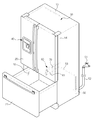
도 1은 본 발명의 실시예에 따른 냉장고의 대략적인 구조를 보인 사시도이고, 도 2는 본 발명의 실시예에 따른 냉장고의 내부구조를 나타낸 것이고, 도 3은 본 발명의 실시예에 따른 냉장고의 정수장치의 결합구조를 나타낸 것이다.1 is a perspective view showing a schematic structure of a refrigerator according to an embodiment of the present invention, Figure 2 shows the internal structure of the refrigerator according to an embodiment of the present invention, Figure 3 is a refrigerator according to an embodiment of the present invention It shows the coupling structure of water purifier.
도 1 내지 도 3을 참조하면, 본 발명의 실시예에 의한 냉장고는 내부에 저장실(11,12)을 구비한 본체(10)와, 저장실(11,12)을 개폐하는 도어(20,21)를 포함한다.1 to 3, the refrigerator according to the embodiment of the present invention includes a
저장실(11,12)은 본체(10) 상부의 냉장실(11)과, 본체(10) 하부의 냉동실(12)로 구비되고, 도어(20,21)는 냉장실(11)을 개폐하는 회전 도어(20)와, 냉동실(12)을 개폐하는 서랍식 도어(21)를 구비할 수 있다.The storage compartments 11 and 12 are provided with a
냉장실(11)에는 선반(18) 및 서랍식 저장용기(19)가 구비되고, 상부에는 구획된 공간에 설치되는 제빙장치(30)가 구비될 수 있다.The refrigerating
도어(20)에는 사용자가 외부에서 음료 또는 얼음을 취출할 수 있는 디스펜서(40)가 구비될 수 있다.The
또한, 냉장고에는 디스펜서(40)로 물을 공급하기 위한 급수시스템(50)이 구비될 수 있다.In addition, the refrigerator may be provided with a
급수시스템(50)은 외부의 급수원(51)과, 급수원(51)과 연결되어 급수를 제어하는 급수밸브(55)와, 급수밸브(55)를 통해 공급되는 물을 정화하거나 저장하는 정수장치(60)와, 급수원(51)으로부터 공급되는 물을 디스펜서(40)로 안내하는 급수관(52,53,54)들을 포함하여 구성될 수 있다.The
급수관(52,53,54)은 급수원(51)과 급수밸브(55)를 연결하는 제1급수관(52)과, 급수밸브(55)와 정수장치(60)를 연결하는 제2급수관(53)과, 정수장치(60)와 디스펜서(40)를 연결하는 제3급수관(54)을 포함하여 구성될 수 있다.The
이러한 급수관(52,53,54), 정수장치(60) 및 급수밸브(55)의 배치는 급수 유로에 따라서 다양한 형태로 설계 변경될 수 있다.The arrangement of the
정수장치(60)는 급수원(51)으로부터 공급되는 물을 필터링하기 위한 필터부(61)와, 필터부(61)에 의해 정화된 물을 저장하는 워터 탱크(70)를 포함하여 구성될 수 있다.The
정수장치(60)는 냉장실(11)의 하부에 배치되되, 냉장실(11)의 공간 효율을 위하여 나란히 배치된 2개의 서랍식 저장용기(19)의 사이 공간에 배치될 수 있다.The
필터부(61)는 필터의 교체를 용이하도록 정수장치(60)로부터 분리 가능하게 설치될 수 있다.The
필터부(61)는 밸브부(63)를 통하여 급수원(51)과 연결될 수 있다.The
밸브부(63)는 필터부(61)가 장착된 경우에는 급수원(51)으로부터 공급된 물을 필터부(61)로 공급하고, 필터부(61)가 분리된 경우에는 급수원(51)으로부터 공급된 물을 워터 탱크(70)로 공급하도록 제어될 수 있다.The
이러한 밸브부(63)는 냉장실(11) 후벽에 배치되는 인렛 커넥터(13)와 접속하여 제2급수관(53)과 연결될 수 있다.The
필터부(61)를 통하여 정화된 물은 워터 탱크(70)로 유입될 수 있다.The purified water through the
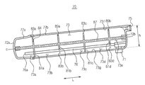
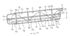
도 4는 본 발명의 실시예에 따른 냉장고용 워터 탱크를 나타낸 분해 사시도이고, 도 5는 본 발명의 실시예에 따른 냉장고용 워터 탱크의 단면도이고, 도 6은 본 발명의 실시예에 따른 냉장고용 워터 탱크의 물 이동경로를 나타낸 것이다.Figure 4 is an exploded perspective view showing a water tank for a refrigerator according to an embodiment of the present invention, Figure 5 is a cross-sectional view of a water tank for a refrigerator according to an embodiment of the present invention, Figure 6 is for a refrigerator according to an embodiment of the present invention The water movement path of the water tank is shown.
워터 탱크(70)는 필터부(61)를 통해 정화된 물이 유입되는 유입구(71)와, 유입구(71)를 통해 유입된 물이 저장되는 워터 저장부(73)와, 워터 저장부(73)에 저장되어 냉각된 물이 토출되는 유출구(75)를 구비한 하우징(77)을 포함하여 구성될 수 있다.The
하우징(77)은 일단(72a)에서 일단(72a)과 마주하는 타단(72b) 까지 길이방향(화살표 L)을 따라 길이가 길게 형성되며 서로 결합되는 제1하우징(77a) 및 제2하우징(77b)을 포함하여 구성될 수 있다. 이는 냉장실(11)에 설치되는 워터 탱크(70)의 사이즈를 줄일 수 있게 되므로 냉장실(11)의 공간 효율성을 향상시킬 수 있게 된다.The
제1하우징(77a) 및 제2하우징(77b)은 사출 성형된 후 그 결합부분이 초음파 또는 진동 융착기를 통해 서로 융착 결합되어 실링됨으로써 그 내부에 물이 저장되는 워터 저장부(73)를 형성할 수 있다.After the
워터 저장부(73)는 하우징(77)과 대응하는 길이를 가지도록 하우징(77) 내부에 형성되고, 그 단면이 원형 형상을 가지도록 마련될 수 있다. 또한, 워터 저장부(73)는 길이방향을 따라 그 직경이 일정한 원통형상으로 이루어지거나, 그 직경이 커지는 테이퍼 형상을 가질 수도 있다.The
유입구(71)는 필터부(61)를 거쳐 정회된 물이 토출되는 밸브부(63)의 토출구(미도시)와 연결되고, 유출구(75)는 냉장실(11)의 후벽 하부에 배치된 아웃렛 커넥터(14)(도 3참조)와 연결될 수 있다.The
아웃렛 커넥터(14)는 디스펜서(40)와 연결된 제3급수관(54)과 연결되고, 유출구(75)를 통해 워터 저장부(73)로부터 토출되는 물은 디스펜서(40)로 공급될 수 있다.The
유입구(71) 및 유출구(75)는 하우징(77)의 타단(72b)과 인접한 위치에 배치될 수 있다. 이는 급수시스템(50)의 급수유로의 구조를 단순화하기 위함이다.The
유입구(71)에는 일측이 유입구(71)에 연결되고, 타측이 하우징(77)의 일단(77a)에 근접한 위치에 배치되는 워터튜브(76)가 연결될 수 있다.One side of the
워터튜브(76)는 유입구(71)로부터 유입된 상온의 물이 유입구(71)와 근접한 위치에 배치되는 유출구(75)쪽으로 바로 토출되는 것을 방지하는 역할을 한다.The
이러한 워터튜브(76)는 유입구(71)가 유출구(75)와 반대편에 위치되는 경우에는 생략될 수 있다.The
즉, 유입구(71) 및 유출구(75)가 서로 인접한 위치에 마련된 경우에는 유입구(71)로부터 유입된 상온의 물이 유출구(75)로부터 멀리 떨어진 위치에 토출되도록 워터튜브(76)가 구비되나, 유입구(71) 및 유출구(75)가 서로 반대편에 위치된 경우에는 워터튜브(76)는 필요치 않게 된다.That is, when the
한편, 유입구(71)로부터 워터 저장부(73)에 유입된 물은 유출구(75)로 이동되나, 이 경우, 유입구(71)를 통해 유입된 상온의 물은 워터 저장부(73)에 저장된 냉각된 물과 바로 섞이게 되고, 이에 따라 유출구(75)로 토출되는 물이 미지근한 상태를 가질 수 있게 된다.On the other hand, the water introduced into the
따라서, 본 실시예의 워터 탱크(70)는 디스펜서(40)로 공급되는 물이 항상 냉각된 상태를 유지할 수 있도록 워터 저장부(73)를 소정의 영역으로 구획하는 구획유닛(80)을 구비할 수 있다.Therefore, the
구획유닛(80)은 유입구(71)로부터 유입된 상온의 물과 워터 저장부(73)에서 냉각된 물이 서로 섞이는 것을 방지함으로써 워터 저장부(73)에서 냉각된 물을 먼저 디스펜서(40)로 토출시킬 수 있게 된다.The
이러한 구획유닛(80)은 워터 저장부(73) 내부를 복수의 저장공간으로 구획하는 복수의 파티션(81)을 구비할 수 있다.The
본 실시예에서는 복수의 파티션(81)이 4개 구비된 예를 설명하나, 이러한 파티션(81)의 수는 변경 가능하다. 일 예로, 워터 저장부(73)를 2개의 저장공간으로 구획하는 경우에는 하나의 파티션(81)만이 구비될 수 있다.In this embodiment, an example in which four
복수의 파티션(81)은 워터 저장부(73)의 길이방향을 따라 이격 배치될 수 있다. 이러한 복수의 파티션(81)은 양단이 워터 저장부(73)의 길이방향 양단부에 각각 지지되는 로드부(87)의 축방향을 따라 이격 배치되어 로드부(87)의 반경방향 외측으로 연장 형성될 수 있다.The plurality of
로드부(87)에서 연장 형성된 복수의 파티션(81)은 제2하우징(77b)의 개구부를 통해 삽입되어 워터 저장부(73)에 장착될 수 있다.The plurality of
워터 저장부(73)에 장착된 로드부(87)는 워터 저장부(73)의 세로방향 길이(h)의 중간 지점(c)에 배치될 수 있다.The
복수의 파티션(81a,81b,81c,8ad)에 의해 구획된 워터 저장부(73)는 복수의 저장공간(73a,73b,73c,73d,73e)을 형성한다.The
복수의 파티션(81a,81b,81c,8ad) 각각에는 복수의 저장공간(73a,73b,73c,73d,73e)을 서로 연통시키기 위한 연통구(83)가 구비될 수 있다.Each of the plurality of
연통구(83)는 서로 인접하는 저장공간을 연통시키기 위한 것으로서, 일부가 개구되거나 관통되도록 형성될 수 있다.The
본 실시예에서는 파티션(81)의 일측을 절개한 절개부(84)를 통하여 워터 저장부(73)의 내면과 절개부(84) 사이에서 연통구(83)를 형성하도록 하였으나, 서로 인접하는 저장공간을 연통시키는 것이라면 연통구(83)의 형상에 대하여는 한정되지 않는다.In the present exemplary embodiment, the
이러한 연통구(83)는 복수의 파티션(81a,81b,81c,8ad)에 각각 형성된 제1 내지 제4연통구(83a,83b,83c,83d)를 포함할 수 있다.The
제1 내지 제4연통구(83a,83b,83c,83d)는 길이방향(L)에 대해 서로 교차되도록 배치될 수 있다. 이는 유입구(71)를 통해 워터 저장부(73)에 유입된 물이 제1 내지 제5저장공간(73a,73b,73c,73d,73e)을 거친 후 유출구(75)로 토출되는 물의 이동경로(90)(도 6참조)가 상하방향으로 유동될 수 있도록 하기 위함이다.The first to
즉 유입구(71)를 거쳐 워터튜브(76)의 토출구(76a)와 인접한 위치에 배치되는 제1연통구(83a)는 워터 저장부(73)의 내면 상측(73f)에 인접하도록 제1파티션(81a)에 배치되고, 제1파티션(81a)에 인접하는 제2파티션(81b)에 배치되는 제2연통구(83b)는 워터 저장부(73)의 내면 하측(73g)에 인접하도록 배치될 수 있다.That is, the
또한, 제3연통구(83c)는 워터 저장부(73)의 내면 상측(73f)에 인접하게 배치되고, 제4연통구(83d)는 워터 저장부(73)의 내면 하측(73g)에 인접하게 배치된다.In addition, the
이러한 구성을 통하여, 워터 저장부(73)에서 유출구(75)로 물이 토출되는 경로인 물 이동경로(90)는 상하 방향으로 지그재그 형태를 이룰 수 있게 된다.Through this configuration, the
이와 같은 경우, 복수의 저장공간(73a,73b,73c,73d,73e)에 각각 저장된 물은 서로 섞이게 되는 것을 줄일 수 있게 되므로, 유입되는 상온의 물에 의하여 워터 저장부(73)에 냉각된 물의 온도가 상승되는 것을 방지할 수 있게 된다.In this case, since the water stored in each of the plurality of
한편, 급수원(51)으로부터 공급되는 물이 워터 저장부(73)에 유입되는 쪽, 즉 워터튜브(76)의 토출구(76a)와 인접한 위치에 배치되는 제1파티션(81a)에 형성된 제1연통구(83a)는 워터 저장부(73)의 상측(73f)에 인접하도록 배치되는 것이 좋다. 이는 유입구(71)를 통해 유입된 상온의 물이 바로 제2저장공간(73b)측으로 유입되어 섞이게 되는 것을 방지하기 위함이다. 이 경우, 한 개의 파티션(81)만이 구비된 경우에도 동일한 효과를 가질 수 있게 된다.On the other hand, the first water formed in the first partition (81a) is disposed on the side in which the water supplied from the
또한, 워터 저장부(73)의 상측(73f)에 인접하게 배치되는 제1 및 제3연통구(83a,83c)의 위치는 워터 저장부(73)의 세로방향 길이(h)의 중간 지점(c)보다 높은 위치에 배치되고, 워터 저장부(73)의 하측(73g)에 인접하게 배치되는 제2 및 제4연통구(83b,83d)의 위치는 워터 저장부(73)의 세로방향 길이(h)의 중간 지점(c)보다 낮은 위치에 배치될 수 있다.In addition, the positions of the first and
이는 복수의 저장공간(73a,73b,73c,73d,73e)들에 각각 저장된 물의 혼합을 최소화 하기 위함이다.This is to minimize the mixing of the water stored in each of the plurality of storage spaces (73a, 73b, 73c, 73d, 73e).
또한, 제2 및 제4연통구(83b,83d)를 구비한 제2 및 제4파티션(81b,83d)의 상측단에는 에어홀(89a,89b)이 구비될 수 있다. 에어홀(89a,89b)은 유출구(75)와 동일 선상에 배치되도록 제2 및 제4파티션(81b,83d)의 상측에서 절개되어 형성될 수 있다. 이러한 에어홀(89a,89b)은 급수에 의해 발생되는 공기를 신속하게 배출하는 기능을 수행한다.In addition,
즉, 워터 저장부(73)에서 유동하는 물 이동경로(90)는 지그재그 형태로 굴곡됨에 따라 굴곡되는 부분에서 부분적으로 와류가 형성되고, 이에 따라 급수원(51)으로부터 공급된 물에 포함된 공기는 워터 저장부(73) 내에서 맴돌아 체류하게 된다.That is, as the
워터 저장부(73) 내에서 체류하는 공기는 높은 수압에 의해 압축된 후 대기와 통해 있는 디스펜서(40)의 출수부와 동일한 대기압이 되면서 팽창되어 디스펜서(40)의 출수부로 잔수를 발생시키는 원인이 되나, 이러한 공기는 에어홀(89a,89b)을 통하여 신속하게 배출될 수 있어 잔수 발생을 방지할 수 있게 된다.Air remaining in the
또한, 본 실시예의 워터 탱크(70)는 저장실에 설치되는 경우 에어 배출과 함께 유입되는 물과 출수되는 물의 선입 선출 효과를 높일 수 있도록 상향 경사지게 배치될 수 있다.In addition, the
즉, 워터 탱크(70)가 저장실(11) 내에 설치된 경우 하우징(77)은 일단(72a)에서 유출구(75)가 형성된 하우징(77)의 타단(72b)까지 상향 경사지게 배치되고, 이에 따라, 유출구(75)는 하우징(77)의 타단(72b) 상측에서 상향 경사지도록 배치될 수 있다.That is, when the
이러한 유출구(75)는 제1연통구(83a), 에어홀(89a), 제3연통구(83c) 및 에어홀(89b)과 동일 선상에 배치되어 워터 저장부(73)내로 유입된 에어는 유출구(75)를 통해 신속하게 배출된다. 이 경우, 제1연통구(83a) 및 제3연통구(83c)는 에어홀(89a,89b)의 기능을 겸할 수 있게 된다.The
한편, 도시하지는 않았으나 하우징(77)의 상측부분이 길이방향을 따라 그 직경이 증가하는 테이퍼 형태를 이루는 경우에는 유출구(75)와 동일 선상에 배치된 제1연통구(83a), 에어홀(89a), 제3연통구(83c) 및 에어홀(89b)은 그 길이방향을 따라 상향 경사지게 배치되므로 저장실(11)에 수평한 상태로 설치될 수 있을 것이다.On the other hand, although not shown, when the upper portion of the
이러한 구성을 통하여 급수원(51)으로부터 공급된 상온의 물은 급수밸브(55)를 통해 조절되어 정수장치(60)로 공급된다. 본 실시예에서는 정수장치(60)는 필터부(61)를 구비하였으나, 필터부(61)가 없는 경우에는 바로 워터 탱크(70)로 유입될 수 있다.The water at room temperature supplied from the
필터부(61)를 통해 정화된 물은 도 6에 도시된 바와 같이 유입구(71)를 통해 유입되고, 유입구(71)에 유입된 물은 워터 튜브(76)를 거쳐 유출구(75)로부터 멀리 떨어진 워터 저장부(73)의 제1저장공간(73a)으로 토출된다.The water purified through the
제1저장공간(73a)에 저장된 물은 제1 내지 제4연통구(83a,83b,83c,83d)를 거쳐 제2 내지 제5저장공간(73b,73c,73d,73e)에 저장되고, 저장된 물은 냉장실(11)의 냉기에 의하여 냉각된다.Water stored in the first storage space (73a) is stored in the second to fifth storage spaces (73b, 73c, 73d, 73e) through the first to fourth communication port (83a, 83b, 83c, 83d), and stored Water is cooled by cold air in the refrigerating
이후, 디스펜서(40)를 작동시키면, 급수원(51)으로부터 상온의 물이 워터 탱크(70)로 공급되나 워터 저장부(73)는 복수의 파티션(81a,81b,81c,8ad)에 구획되므로 상온의 물과 냉각된 물이 바로 섞이게 되는 것을 방지하게 된다.Thereafter, when the
즉, 유입구(71)를 통해 워터 저장부(73)로 유입된 상온의 물이 유출구(75)로 토출되는 물 이동경로(90)는 상하 방향으로 지그재그 형태를 이루게 되므로, 상온의 물과 냉각된 물의 혼합은 현저히 줄어들게 된다.That is, since the
이에 따라, 디스펜서(40)로 공급되는 물은 항상 냉각된 상태를 유지할 수 있게 되므로, 소비자는 최대한 시원한 물을 공급받을 수 있게 된다.Accordingly, since the water supplied to the
또한, 급수를 통해 워터 저장부(73)에 공급된 공기는 길이방향을 따라 나란히 배치되는 제1연통구(83a), 에어홀(89a), 제3연통구(83c) 및 에어홀(89b)를 통해 유출구(75)로 신속하게 배출됨으로써, 밸브의 개폐에 따라 디스펜서(40)에서 발생되는 잔수를 예방할 수 있게 된다. 즉, 디스펜싱 동작에 대한 신호를 제공하는 레버가 off된 뒤에도 디스펜서의 취수관에서 물이 떨어지는 현상을 방지하게 된다.In addition, the air supplied to the
또한, 워터 탱크(70) 내부의 냉각된 물의 선입 선출을 위하여 하우징(70)의 형상을 지그재그 형태로 형성하는 경우에는 워터 탱크(70)의 사이즈 증가에 따라 저장실의 공간 효율성은 저하될 뿐만 아니라, 성형의 곤란함 등으로 생산성은 저하될 수 있으나, 본 실시예의 워터 탱크(70)는 구획유닛(80)을 통하여 상하로 유동하는 물 이동경로(90)를 구현하게 되므로 구조가 간단하여 생산성이 향상되게 된다.In addition, when the
즉, 제1하우징(77a), 제2하우징(77b) 및 구획유닛(80)을 별도로 사출 성형 한 후 구획유닛(80)을 제1,2하우징(77a,77b) 내에 삽입 안착시킨 상태에서 제1,2하우징(77a,77b)의 접합면을 융착시킴에 따라 워터 탱크(70)를 제조할 수 있어 워터 탱크(70)의 신뢰성은 향상된다.That is, the injection molding of the
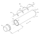
이하에서는 본 발명의 다른 실시예에 대해 설명한다. 이상에서 설명한 본 발명의 일 실시예와 동일한 부분에 대해서는 설명을 생략한다. 도 7은 본 발명의 다른 실시예에 의한 워터 탱크의 구획유닛을 나타낸 분해 사시도이고, 도 8은 본 발명의 다른 실시예에 의한 워터 탱크의 물 이동경로를 나타낸 것이다.Hereinafter, another embodiment of the present invention will be described. Description of the same parts as in the embodiment of the present invention described above will be omitted. Figure 7 is an exploded perspective view showing a partition unit of a water tank according to another embodiment of the present invention, Figure 8 shows a water movement path of the water tank according to another embodiment of the present invention.
도 7 및 도8을 참조하면, 본 실시예의 워터 저장부(73)를 복수의 저장공간으로 구획하는 구획유닛(100)의 파티션(110)은 나선 형태로 구비될 수 있다.7 and 8, the
구획유닛(100)은 양단이 워터 저장부(73)의 길이방향(L) 양단부에 각각 지지되는 로드부(110)와, 로드부(110)의 축방향을 따라 나선 형태로 연장 형성된 파티션(120)을 포함하여 구성될 수 있다.The
파티션(120)은 로드부(120)로부터 워터 저장부(73)의 내면까지 연장 형성될 수 있다. 또한, 워터 저장부(73)의 상측(73f)에 인접한 파티션(120)에는 에어 배출을 위한 에어홀(130)이 구비될 수 있다.The
본 실시예에서는 파티션(120)이 로드부(120)에서 연장 형성되도록 하였으나, 도 9에 도시된 바와 같이 구획유닛(100)은 나선 형태의 파티션(120)만으로 형성될 수 있다. 이 경우, 나선 형태의 파티션(120)의 양단이 각각 워터 저장부(73)의 양단부에 지지될 수 있다.In the present embodiment, the
또한, 나선 형태의 파티션(120)은 그 형상에 의하여 워터 저장부(73)의 내벽과 파티션(120) 사이에서 개구된 연통구(121)를 형성하고, 연통구(121)를 통해 파티션(120)에 구획된 복수의 저장공간을 연통시킬 수 있게 된다.In addition, the
이러한 구성을 통해, 나선 형태의 파티션(120)을 갖는 구획유닛(70)을 워터 저장부(73)에 장착한 경우에는 워터 저장부(73)는 복수의 저장공간으로 구획되게 되고, 유입구(71) 및 워터튜브(76)를 통해 유입된 상온의 물은 워터 저장부(73)에서 냉각된 물과 혼합되는 것을 줄일 수 있게 된다.Through this configuration, when the
즉, 워터 저장부(73) 내에서 유출구(75)로 토출되는 물 이동경로(95)는 도 8에 도시된 바와 같이 나선형의 파티션(120)을 따라 나선 형태의 상하 방향으로 유동하게 되므로, 워터 저장부(73)에 유입된 상온의 물의 혼합을 줄일 수 있게 된다.That is, since the
이상에서는 특정의 실시예에 대하여 도시하고 설명하였다. 그러나, 상기한 실시예에만 한정되지 않으며, 발명이 속하는 기술분야에서 통상의 지식을 가진 자라면 이하의 청구범위에 기재된 발명의 기술적 사상의 요지를 벗어남이 없이 얼마든지 다양하게 변경 실시할 수 있을 것이다.
In the above, specific embodiments have been illustrated and described. However, the present invention is not limited to the above-described embodiments, and those skilled in the art may make various changes without departing from the spirit of the technical idea of the invention as set forth in the claims below. .
10: 본체, 20: 도어,
30: 제빙장치, 40: 디스펜서,
50: 급수시시템, 61: 필터부,
70: 워터탱크, 71: 유입구,
73: 워터저장부, 75: 유출구,
80: 구획유닛, 81: 파티션,
83: 연통구, 84: 절개부,
87: 로드부, 89: 에어홀.10: main body, 20: door,
30: ice maker, 40: dispenser,
50: water supply system, 61: filter unit,
70: water tank, 71: inlet,
73: water reservoir, 75: outlet,
80: compartment unit, 81: partition,
83: communication port, 84: incision,
87: rod part, 89: air hole.
Claims (32)
상기 워터 저장부를 복수의 저장공간으로 구획하도록 상기 워터 저장부에 설치되는 적어도 하나 이상의 파티션을 구비한 구획유닛;과,
상기 적어도 하나 이상의 파티션에 의해 구획된 상기 복수의 저장공간을 서로 연통시키도록 상기 적어도 하나 이상의 파티션에 형성된 연통구;와,
상기 유입구를 통해 상기 워터 저장부에 유입된 물이 상기 연통구를 통과하여 상기 유출구로 이동되는 물 이동경로;를 포함하고,
상기 연통구는 상기 물 이동경로가 구불구불(serpentine)한 형태를 이루도록 상기 적어도 하나 이상의 파티션에 배치되는 것을 특징으로 하는 냉장고용 워터 탱크.A housing having an inlet, an outlet, and a water storage unit for storing the water introduced through the inlet;
A partition unit having at least one partition installed in the water storage unit so as to partition the water storage unit into a plurality of storage spaces;
A communication port formed in the at least one partition to communicate the plurality of storage spaces partitioned by the at least one partition with each other; and
And a water movement path through which the water introduced into the water storage unit through the inlet passes through the communication port and moves to the outlet.
The communication port is a water tank for a refrigerator, characterized in that disposed in the at least one partition so that the water path is serpentine (serpentine) form.
상기 워터 저장부는 길이방향으로 길이가 길게 형성된 것을 특징으로 하는 냉장고용 워터 탱크.The method of claim 1,
The water tank for a refrigerator, characterized in that the water storage is formed long in the longitudinal direction.
상기 적어도 하나 이상의 파티션에는 절개된 절개부가 마련되고,
상기 연통구는 상기 절개부와 상기 하우징 내면 사이에 형성되는 것을 특징으로 하는 냉장고용 워터 탱크.The method of claim 1,
The at least one partition is provided with a cut incision,
The communication port is a water tank for a refrigerator, characterized in that formed between the cutout and the inner surface of the housing.
상기 유입구 및 상기 유출구는 상기 워터 저장부의 상기 길이방향 양단부에 각각 배치되고,
상기 유입구와 인접한 위치에 배치되는 상기 적어도 하나 이상의 파티션 중 하나에 형성된 연통구는 상기 워터 저장부 상측에 인접하게 배치되는 것을 특징으로 하는 냉장고용 워터 탱크.The method of claim 2,
The inlet and the outlet are respectively disposed in the longitudinal both ends of the water reservoir,
The communication port formed in one of the at least one partition disposed in a position adjacent to the inlet is a water tank for a refrigerator, characterized in that disposed adjacent to the upper side of the water storage.
상기 유출구 및 상기 유입구는 상기 워터 저장부의 상기 길이방향 일단부에 배치되고,
상기 유입구를 통해 유입되는 물이 상기 길이방향 일단부 반대편의 타단부에 인접한 위치에서 토출되도록 상기 유입구와 연통되는 워터튜브를 포함하는 것을 특징으로 하는 냉장고용 워터 탱크.The method of claim 2,
The outlet and the inlet are disposed at one end of the water reservoir in the longitudinal direction;
And a water tube communicating with the inlet so that water introduced through the inlet is discharged at a position adjacent to the other end opposite the one end in the longitudinal direction.
상기 구획유닛은 양단이 상기 길이방향 양단부에 각각 지지되는 로드부를 포함하고, 상기 적어도 하나 이상의 파티션은 상기 로드부의 반경방향 외측으로 연장 형성된 것을 특징으로 하는 냉장고용 워터 탱크.The method of claim 2,
The partition unit includes a rod portion, each end of which is supported at both ends of the longitudinal direction, wherein the at least one or more partitions are formed to extend radially outward of the rod portion.
상기 구획유닛은 양단이 상기 길이방향 양단부에 각각 지지되는 로드부를 포함하고, 상기 적어도 하나 이상의 파티션은 나선 형상을 가지도록 상기 로드부에서 연장 형성된 것을 특징으로 하는 냉장고용 워터 탱크.The method of claim 2,
The partition unit includes a rod portion, each end of which is supported at both ends of the longitudinal direction, wherein the at least one or more partitions extend from the rod portion to have a spiral shape.
상기 적어도 하나 이상의 파티션 중 상기 연통구가 상기 워터 저장부의 하측에 인접하게 배치된 파티션 상측에는 에어 배출을 위한 에어홀이 더 구비되는 것을 특징으로 하는 냉장고용 워터 탱크.The method of claim 3, wherein
The water tank for the refrigerator, characterized in that the air hole for air discharge is further provided on the partition side of the at least one partition in which the communication port is disposed adjacent to the lower side of the water storage unit.
상기 적어도 하나 이상의 파티션 중 상기 연통구가 상기 워터 저장부의 상측에 인접하게 배치된 파티션에 형성된 연통구는 상기 하우징의 세로방향 길이의 중간 지점보다 상대적으로 높은 위치에 배치되는 것을 특징으로 하는 냉장고용 워터 탱크.The method of claim 2,
The communication port of the at least one partition formed in the partition in which the communication port is disposed adjacent to the upper side of the water storage portion is a water tank for a refrigerator, characterized in that disposed in a position relatively higher than the middle point of the longitudinal length of the housing. .
상기 적어도 하나 이상의 파티션 중 상기 연통구가 상기 워터 저장부의 하측에 인접하게 배치된 파티션에 형성된 연통구는 상기 하우징의 세로방향 길이의 중앙보다 상대적으로 낮은 위치에 배치되는 것을 특징으로 하는 냉장고용 워터 탱크.The method of claim 9,
The communication port of the at least one partition formed in the partition in which the communication port is disposed adjacent to the lower side of the water storage portion is a water tank for a refrigerator, characterized in that disposed in a position relatively lower than the center of the longitudinal length of the housing.
상기 하우징은 상기 길이방향 일측을 형성하는 제1하우징과, 상기 길이방향 타측을 형성하는 제2하우징을 포함하고, 상기 제1하우징 및 상기 제2하우징은 서로 결합되고,
상기 구획유닛은 사출 성형되어 상기 하우징 내부에 장착되는 것을 특징으로 하는 냉장고용 워터 탱크.In the second,
The housing includes a first housing forming the longitudinal one side and a second housing defining the other longitudinal direction, wherein the first housing and the second housing are coupled to each other,
The compartment unit is a water tank for a refrigerator, characterized in that the injection molding is mounted inside the housing.
상기 제1하우징 및 상기 제2하우징은 융착 결합된 것을 특징으로 하는 냉장고용 워터 탱크.12. The method of claim 11,
The water tank for the refrigerator, characterized in that the first housing and the second housing are fusion-bonded.
상기 구획유닛은 일단이 상기 제1하우징에 지지되며 타단이 상기 제2하우징에 지지되도록 상기 길이방향을 따라 연장된 로드부를 포함하고, 상기 로드부는 상기 워터 저장부의 세로길이 중앙부에 배치되고,
상기 적어도 하나 이상의 파티션은 상기 로드부로부터 상기 하우징 내면을 향해 연장 형성된 것을 특징으로 하는 냉장고용 워터 탱크.12. The method of claim 11,
The partition unit includes a rod portion extending in the longitudinal direction such that one end thereof is supported by the first housing and the other end thereof is supported by the second housing, wherein the rod portion is disposed at a central length of the water storage portion.
And the at least one partition extends from the rod toward the inner surface of the housing.
상기 워터 저장부를 구획하도록 상기 워터 저장부에서 상기 길이방향을 따라 이격 배치되며 각각 개구된 연통구가 형성된 복수의 파티션을 갖는 구획유닛;을 포함하고,
상기 물 이동경로가 구불구불한 형태를 이루도록 상기 복수의 파티션 중 하나에 인접하는 파티션에 형성된 연통구는 상기 하나의 파티션에 형성된 연통구와 서로 교차(cross)배열된 것을 특징으로 하는 냉장고.A housing having a water storage unit having a length extending in a horizontal direction from one end to the other end, and a water movement path through which water introduced into the water storage unit near the one end is discharged to an outlet disposed near the other end;
And a partition unit having a plurality of partitions spaced apart in the water direction from the water storage part along the length direction so as to partition the water storage part, and each having a communication port opened therein.
And a communication port formed in a partition adjacent to one of the plurality of partitions so that the water movement path has a serpentine shape is cross-aligned with the communication hole formed in the one partition.
급수원, 일측이 상기 급수원에 연결되고 타측이 상기 워터 저장부의 타단 근처에 연결되는 유입구를 더 포함하고,
상기 유입구를 통해 유입된 물을 상기 하우징의 일단 근처에서 토출시키도록 상기 유입구와 연통되는 워터튜브를 더 구비하는 것을 특징으로 하는 냉장고.The method of claim 14,
Water supply source, one side is further connected to the water supply source and the other side further comprises an inlet connected near the other end of the water storage unit,
And a water tube communicating with the inlet for discharging water introduced through the inlet near one end of the housing.
상기 복수의 파티션 중 상기 워터튜브의 토출구와 인접한 파티션에 형성된 연통구는 상기 워터 저장부의 상부에 인접하도록 배치되는 것을 특징으로 하는 냉장고.16. The method of claim 15,
The communication port formed in the partition adjacent to the discharge port of the water tube of the plurality of partitions, characterized in that the refrigerator is arranged to be adjacent to the upper portion of the water storage.
상기 급수원과 상기 유입구 사이에는 상기 급수원으로부터 공급되는 물을 필터링하는 필터부가 구비되는 것을 특징으로 하는 냉장고.16. The method of claim 15,
And a filter unit for filtering the water supplied from the water source between the water source and the inlet.
상기 유출구는 상기 하우징의 타단 상측에 배치되고,
상기 유출구와 동일 선상에 위치하는 상기 복수의 파티션 상측에는 각각 에어 배출을 위한 에어홀이 형성된 것을 특징으로 하는 냉장고.The method of claim 14,
The outlet is disposed above the other end of the housing,
And an air hole for discharging air is formed above the plurality of partitions positioned on the same line as the outlet.
상기 하우징은 서로 결합되도록 상기 길이방향 일측을 형성하는 제1하우징 및 상기 길이방향 타측을 형성하는 제2하우징을 포함하고,
상기 제1하우징 및 상기 제2하우징은 융착 결합되고, 상기 구획유닛은 상기 하우징 내부에 장착되는 것을 특징으로 하는 냉장고.The method of claim 14,
The housing includes a first housing for forming the longitudinal one side to be coupled to each other and a second housing for forming the other longitudinal direction,
And the first housing and the second housing are fusion-bonded, and the compartment unit is mounted inside the housing.
저장실을 구비한 본체를 더 포함하고,
상기 하우징은 상기 유출구가 상향 경사지도록 상기 저장실에 배치된 것을 특징으로 하는 냉장고.19. The method of claim 18,
Further comprising a body having a storage compartment,
And the housing is disposed in the storage compartment such that the outlet is inclined upward.
상기 구획유닛은 상기 길이방향을 따라 연장 형성된 로드부를 포함하고,
상기 로드부는 양단이 각각 상기 제1하우징 및 상기 제2하우징에 지지되어 상기 워터 저장부의 중앙부에 배치되고,
상기 복수의 파티션은 상기 로드부로부터 연장 형성된 것을 특징으로 하는 냉장고.The method of claim 19,
The partition unit includes a rod portion extending in the longitudinal direction,
Both ends of the rod are supported by the first housing and the second housing, respectively, and are disposed in the center of the water storage unit.
The plurality of partitions, characterized in that the refrigerator extending from the rod.
상기 복수의 파티션 각각에는 절개된 절개부가 마련되고,
상기 연통구는 상기 절개부와 상기 하우징 내면 사이에 형성되는 것을 특징으로 하는 냉장고.The method of claim 21,
Each of the plurality of partitions is provided with a cut out portion,
The communication port is a refrigerator, characterized in that formed between the cutout and the inner surface of the housing.
상기 복수의 파티션은 나선 형상을 가지는 것을 특징으로 하는 냉장고.The method of claim 21,
And the plurality of partitions have a spiral shape.
상기 유출구와 연결되는 디스펜서를 더 포함하는 것을 특징으로 하는 냉장고.The method of claim 14,
The refrigerator further comprises a dispenser connected to the outlet.
급수원, 상기 급수원과 연결된 유입구를 더 포함하고,
상기 유입구는 상기 상기 워터 저장부의 일단 근처에 배치되는 것을 특징으로 하는 냉장고.The method of claim 14,
Water supply source, and further comprising an inlet connected to the water supply source,
And the inlet is arranged near one end of the water reservoir.
상기 워터 저장부를 복수의 저장공간으로 구획하도록 상기 길이방향을 따라 이격 배치되며 개구된 연통구를 구비한 적어도 하나 이상의 파티션;을 포함하는 것을 특징으로 하는 냉장고용 워터 탱크.A housing having an inlet, an outlet, and a long water reservoir;
And at least one partition spaced apart in the longitudinal direction so as to partition the water storage into a plurality of storage spaces and having an open communication port.
상기 유입구 및 상기 유출구는 상기 길이방향 양단부에 각각 배치되는 것을 특징으로 하는 냉장고용 워터 탱크.The method of claim 25,
And said inlet and said outlet are respectively disposed at both ends of said longitudinal direction.
상기 유입구 및 상기 유출구는 상기 길이방향 일단부에 배치되고, 상기 유입구로 유입되는 물을 상기 길이방향 일단부 반대편의 타단부에 토출시키도록 상기 유입구와 연결된 워터튜브를 더 포함하는 것을 특징으로 하는 냉장고용 워터 탱크.The method of claim 25,
The inlet and the outlet is disposed in the one end in the longitudinal direction, further comprising a water tube connected to the inlet to discharge the water flowing into the inlet to the other end opposite the longitudinal one end Water tank.
상기 파티션은 복수개 마련되고, 상기 연통구는 상기 길이방향에 대해 상하 교대로 상기 복수의 파티션에 각각 배치된 것을 특징으로 하는 냉장고용 워터 탱크.The method of claim 25,
A plurality of partitions are provided, and the communication port is a water tank for a refrigerator, characterized in that arranged in each of the plurality of partitions alternately up and down with respect to the longitudinal direction.
상기 적어도 하나 이상의 파티션은 나선 형상으로 이루어진 것을 특징으로 하는 냉장고용 워터 탱크.The method of claim 25,
The water tank for a refrigerator, characterized in that the at least one partition has a spiral shape.
상기 복수의 파티션 중 상기 연통구가 상기 워터 저장부의 하부에 인접하게 배치된 파티션들의 상측에는 에어 배출을 위한 에어홀이 형성된 것을 특징으로 하는 냉장고용 워터 탱크.30. The method of claim 29,
The water tank for a refrigerator, characterized in that an air hole for air discharge is formed above the partitions in which the communication port is arranged adjacent to the lower portion of the water storage unit.
상기 제1하우징 및 상기 제2하우징 내부에 상기 구획유닛을 삽입 장착하고,
상기 제1하우징과 상기 제2하우징을 융착 결합하는 것을 특징으로 하는 냉장고용 워터 탱크의 제조방법.Injection molding the first housing, the second housing and the partition unit,
Inserting the compartment unit into the first housing and the second housing;
The method of manufacturing a water tank for a refrigerator, characterized in that the first housing and the second housing by fusion bonding.
Priority Applications (4)
| Application Number | Priority Date | Filing Date | Title |
|---|---|---|---|
| KR1020100102907A KR20120041450A (en) | 2010-10-21 | 2010-10-21 | Refrigerator with water tnak for refrigerator |
| US13/200,924 US20120096888A1 (en) | 2010-10-21 | 2011-10-05 | Refrigerator with water tank |
| EP11184950.1A EP2444763A3 (en) | 2010-10-21 | 2011-10-13 | Refrigerator with water tank |
| CN2011103227494A CN102455101A (en) | 2010-10-21 | 2011-10-21 | Refrigerator with water tank |
Applications Claiming Priority (1)
| Application Number | Priority Date | Filing Date | Title |
|---|---|---|---|
| KR1020100102907A KR20120041450A (en) | 2010-10-21 | 2010-10-21 | Refrigerator with water tnak for refrigerator |
Publications (1)
| Publication Number | Publication Date |
|---|---|
| KR20120041450A true KR20120041450A (en) | 2012-05-02 |
Family
ID=44862545
Family Applications (1)
| Application Number | Title | Priority Date | Filing Date |
|---|---|---|---|
| KR1020100102907A KR20120041450A (en) | 2010-10-21 | 2010-10-21 | Refrigerator with water tnak for refrigerator |
Country Status (4)
| Country | Link |
|---|---|
| US (1) | US20120096888A1 (en) |
| EP (1) | EP2444763A3 (en) |
| KR (1) | KR20120041450A (en) |
| CN (1) | CN102455101A (en) |
Cited By (7)
| Publication number | Priority date | Publication date | Assignee | Title |
|---|---|---|---|---|
| US9506682B2 (en) | 2013-02-20 | 2016-11-29 | Lg Electronics Inc. | Refrigerator |
| KR20180136312A (en) * | 2017-06-14 | 2018-12-24 | 엘지전자 주식회사 | Refrigerator |
| KR20220076744A (en) * | 2020-12-01 | 2022-06-08 | 주식회사 마이크로필터 | Filter assembly and refrigerator including the same |
| KR20220076746A (en) * | 2020-12-01 | 2022-06-08 | 주식회사 마이크로필터 | Filter assembly and refrigerator including the same |
| KR20220076745A (en) * | 2020-12-01 | 2022-06-08 | 주식회사 마이크로필터 | Filter assembly and refrigerator including the same |
| WO2022119251A1 (en) * | 2020-12-01 | 2022-06-09 | 주식회사 마이크로필터 | Water purifier filter assembly and refrigerator comprising same |
| WO2023128165A1 (en) * | 2021-12-28 | 2023-07-06 | 삼성전자주식회사 | Refrigerator |
Families Citing this family (4)
| Publication number | Priority date | Publication date | Assignee | Title |
|---|---|---|---|---|
| KR101609438B1 (en) | 2014-02-11 | 2016-04-05 | 엘지전자 주식회사 | Refrigerator |
| CN104757880A (en) * | 2015-04-10 | 2015-07-08 | 佛山市美的清湖净水设备有限公司 | Cabin type liquid storage container for clean drinking equipment and clean drinking equipment with cabin type liquid storage container |
| US11203516B2 (en) | 2019-01-23 | 2021-12-21 | Haws Corporation | Enhanced tankless evaporator |
| US20230266056A1 (en) * | 2022-02-23 | 2023-08-24 | Bsh Home Appliances Corporation | Multi-chambered water tank for confined spaces in a refrigeration appliance |
Family Cites Families (23)
| Publication number | Priority date | Publication date | Assignee | Title |
|---|---|---|---|---|
| US1557200A (en) * | 1924-03-29 | 1925-10-13 | Delco Light Co | Refrigerating apparatus |
| US3079498A (en) * | 1960-07-15 | 1963-02-26 | Ruffin Hoebel Corp | Swimming pool water purifier |
| US3521703A (en) * | 1968-10-01 | 1970-07-28 | Gen Electric | Spiral core precooler for water coolers |
| US4036620A (en) * | 1976-06-04 | 1977-07-19 | General Motors Corporation | Water chilling tank for refrigerator |
| US4550771A (en) * | 1980-11-11 | 1985-11-05 | Morteza Arbabian | Waste water heat recovery apparatus |
| US4739629A (en) * | 1987-03-18 | 1988-04-26 | General Electric Company | Water storage tank for use in the fresh food compartment of a refrigerator |
| US4922731A (en) * | 1988-09-30 | 1990-05-08 | Texas Instruments Incorporated | Quartz conductive baffles for heat removal and method |
| US5078209A (en) * | 1991-02-06 | 1992-01-07 | Modine Manufacturing Co. | Heat exchanger assembly |
| US5271245A (en) * | 1992-08-20 | 1993-12-21 | Ac&R Components, Inc. | Two-stage helical oil separator |
| DE19802012C2 (en) * | 1998-01-21 | 2002-05-23 | Modine Mfg Co | Caseless plate heat exchanger |
| AR023533A1 (en) * | 2000-04-18 | 2002-09-04 | Haarlow Corp | AUTOMATIC DEVICE FOR THE DOSAGE EXPENDED OF MEDIUM AND LOW TEMPERATURE DENSE BODIES. |
| KR100356542B1 (en) * | 2000-12-29 | 2002-10-19 | 삼성전자 주식회사 | Refrigerator Having Freezing Compartment |
| US20050160759A1 (en) * | 2004-01-26 | 2005-07-28 | Oasis Corporation | Chiller reservoir with internal baffles |
| CN100549590C (en) * | 2005-05-11 | 2009-10-14 | 乐金电子(天津)电器有限公司 | The supply tank mounting structure of dispenser for refrigerator |
| US7866465B2 (en) * | 2005-09-27 | 2011-01-11 | Alexander Dverin | Multi-compartment storage and mixing vessel |
| KR100692221B1 (en) * | 2005-09-28 | 2007-03-09 | 삼성전자주식회사 | Refrigerator and watertank for the same |
| US8061150B2 (en) * | 2006-02-15 | 2011-11-22 | Lg Electronics Inc. | Apparatus for supercooling, and method of operating the same |
| US8833100B2 (en) * | 2006-12-28 | 2014-09-16 | Whirlpool Corporation | Water reservoir pressure vessel |
| EP2212209A2 (en) * | 2007-10-26 | 2010-08-04 | 3M Innovative Properties Company | Liquid storage tank with internal flow control baffle and methods |
| US9115920B2 (en) * | 2009-01-07 | 2015-08-25 | Samsung Electronics Co., Ltd. | Water filter device and refrigerator having the same |
| US8938985B2 (en) * | 2009-03-10 | 2015-01-27 | Samsung Electronics Co., Ltd. | Refrigerator |
| KR20110001556A (en) * | 2009-06-30 | 2011-01-06 | 삼성전자주식회사 | Refrigerator and water purification device |
| US20120134868A1 (en) * | 2010-11-29 | 2012-05-31 | Kingston Comp Co., Ltd. | Rotary sliding-vane compressor |
-
2010
- 2010-10-21 KR KR1020100102907A patent/KR20120041450A/en not_active Application Discontinuation
-
2011
- 2011-10-05 US US13/200,924 patent/US20120096888A1/en not_active Abandoned
- 2011-10-13 EP EP11184950.1A patent/EP2444763A3/en not_active Withdrawn
- 2011-10-21 CN CN2011103227494A patent/CN102455101A/en active Pending
Cited By (13)
| Publication number | Priority date | Publication date | Assignee | Title |
|---|---|---|---|---|
| US11754334B2 (en) | 2013-02-20 | 2023-09-12 | Lg Electronics Inc. | Refrigerator |
| US9664432B2 (en) | 2013-02-20 | 2017-05-30 | Lg Electronics Inc. | Refrigerator |
| US9841226B2 (en) | 2013-02-20 | 2017-12-12 | Lg Electronics Inc. | Refrigerator |
| US9506682B2 (en) | 2013-02-20 | 2016-11-29 | Lg Electronics Inc. | Refrigerator |
| US10288344B2 (en) | 2013-02-20 | 2019-05-14 | Lg Electronics Inc. | Refrigerator |
| US10690398B2 (en) | 2013-02-20 | 2020-06-23 | Lg Electronics, Inc. | Refrigerator |
| US11326832B2 (en) | 2013-02-20 | 2022-05-10 | Lg Electronics Inc. | Refrigerator |
| KR20180136312A (en) * | 2017-06-14 | 2018-12-24 | 엘지전자 주식회사 | Refrigerator |
| KR20220076746A (en) * | 2020-12-01 | 2022-06-08 | 주식회사 마이크로필터 | Filter assembly and refrigerator including the same |
| KR20220076745A (en) * | 2020-12-01 | 2022-06-08 | 주식회사 마이크로필터 | Filter assembly and refrigerator including the same |
| WO2022119251A1 (en) * | 2020-12-01 | 2022-06-09 | 주식회사 마이크로필터 | Water purifier filter assembly and refrigerator comprising same |
| KR20220076744A (en) * | 2020-12-01 | 2022-06-08 | 주식회사 마이크로필터 | Filter assembly and refrigerator including the same |
| WO2023128165A1 (en) * | 2021-12-28 | 2023-07-06 | 삼성전자주식회사 | Refrigerator |
Also Published As
| Publication number | Publication date |
|---|---|
| EP2444763A3 (en) | 2014-01-08 |
| CN102455101A (en) | 2012-05-16 |
| EP2444763A2 (en) | 2012-04-25 |
| US20120096888A1 (en) | 2012-04-26 |
Similar Documents
| Publication | Publication Date | Title |
|---|---|---|
| KR20120041450A (en) | Refrigerator with water tnak for refrigerator | |
| US9216914B2 (en) | Water filter device and refrigerator having the same | |
| US11148925B2 (en) | Refrigerator equipped with apparatus for producing carbonated water | |
| US3982406A (en) | Refrigerator water storage and dispensing system with water filter | |
| EP2206996B1 (en) | Refrigerator having a water filter device | |
| KR101665417B1 (en) | Refrigerator | |
| US8833100B2 (en) | Water reservoir pressure vessel | |
| KR101717701B1 (en) | Water filter device and refrigerator having the same | |
| EP2407737B1 (en) | Refrigerator | |
| US20120297814A1 (en) | Refrigerator and water tank assembly for refrigerator | |
| EP3553431B1 (en) | Refrigerator | |
| US9492796B2 (en) | Refrigerator equipped with apparatus for producing carbonated water | |
| CN102472548B (en) | Refrigerator | |
| US20110056222A1 (en) | Refrigerator | |
| US7805956B2 (en) | Additive-storing tank assembly and refrigerator having the same | |
| BRPI0902419B1 (en) | cooler | |
| EP2772712A2 (en) | Refrigerator equipped with apparatus for producing carbonated water | |
| KR20170067705A (en) | Refrigerator | |
| KR20170123136A (en) | Water Supplying Apparatus Providing Cold Water and Soda Water with Single Cooling Cycle | |
| CN116324317A (en) | Refrigerator with a refrigerator body | |
| KR101079469B1 (en) | Refrigerator | |
| KR102131232B1 (en) | Refrigerator | |
| KR20240051625A (en) | Refrigerator | |
| KR100704662B1 (en) | Refrigerator | |
| KR101150590B1 (en) | Refrigerator and water tank for refigerator |
Legal Events
| Date | Code | Title | Description |
|---|---|---|---|
| WITN | Application deemed withdrawn, e.g. because no request for examination was filed or no examination fee was paid |