KR20120041176A - System and method of communication for electronic apparatuses - Google Patents
System and method of communication for electronic apparatuses Download PDFInfo
- Publication number
- KR20120041176A KR20120041176A KR1020117029603A KR20117029603A KR20120041176A KR 20120041176 A KR20120041176 A KR 20120041176A KR 1020117029603 A KR1020117029603 A KR 1020117029603A KR 20117029603 A KR20117029603 A KR 20117029603A KR 20120041176 A KR20120041176 A KR 20120041176A
- Authority
- KR
- South Korea
- Prior art keywords
- frequency
- communication
- energy supply
- electrical energy
- functional modules
- Prior art date
Links
Images


Classifications
-
- G—PHYSICS
- G05—CONTROLLING; REGULATING
- G05B—CONTROL OR REGULATING SYSTEMS IN GENERAL; FUNCTIONAL ELEMENTS OF SUCH SYSTEMS; MONITORING OR TESTING ARRANGEMENTS FOR SUCH SYSTEMS OR ELEMENTS
- G05B19/00—Programme-control systems
- G05B19/02—Programme-control systems electric
- G05B19/04—Programme control other than numerical control, i.e. in sequence controllers or logic controllers
- G05B19/042—Programme control other than numerical control, i.e. in sequence controllers or logic controllers using digital processors
- G05B19/0423—Input/output
- G05B19/0425—Safety, monitoring
-
- G—PHYSICS
- G05—CONTROLLING; REGULATING
- G05B—CONTROL OR REGULATING SYSTEMS IN GENERAL; FUNCTIONAL ELEMENTS OF SUCH SYSTEMS; MONITORING OR TESTING ARRANGEMENTS FOR SUCH SYSTEMS OR ELEMENTS
- G05B2219/00—Program-control systems
- G05B2219/20—Pc systems
- G05B2219/21—Pc I-O input output
- G05B2219/21155—Over voltage protection
-
- G—PHYSICS
- G05—CONTROLLING; REGULATING
- G05B—CONTROL OR REGULATING SYSTEMS IN GENERAL; FUNCTIONAL ELEMENTS OF SUCH SYSTEMS; MONITORING OR TESTING ARRANGEMENTS FOR SUCH SYSTEMS OR ELEMENTS
- G05B2219/00—Program-control systems
- G05B2219/20—Pc systems
- G05B2219/25—Pc structure of the system
- G05B2219/25314—Modular structure, modules
-
- G—PHYSICS
- G05—CONTROLLING; REGULATING
- G05B—CONTROL OR REGULATING SYSTEMS IN GENERAL; FUNCTIONAL ELEMENTS OF SUCH SYSTEMS; MONITORING OR TESTING ARRANGEMENTS FOR SUCH SYSTEMS OR ELEMENTS
- G05B2219/00—Program-control systems
- G05B2219/20—Pc systems
- G05B2219/26—Pc applications
- G05B2219/2613—Household appliance in general
Abstract
본 발명은, 전자 장치가 접속되어 있는 전기 에너지 공급 장치의 잠재적인 장애 이벤트(potential failure event)에 면역성이 있는 전자 장치로의 응용을 위한 통신 시스템을 언급하고 있다. 상기 시스템은, 기능 모듈(1, 2, 3, 4)을 구비하고 있고, 여기서 적어도 하나의 기능 모듈(1, 2, 3, 4)은 처리 장치(5)를 갖고 있으며, 적어도 하나의 기능 모듈(1, 2, 3, 4)은 처리 장치(5)에 의해 제어가능한 장치(6, 7)를 갖고 있다. 이들 기능 모듈(1, 2, 3, 4)은, 전기 에너지 공급 장치(8)에 의해 공급된 미리 정해진 주파수에서 교류 전압에 의해 전기적으로 전력이 공급된다. 기능 모듈(1, 2, 3, 4)은 각각 전원 버스(9, 10) 및 통신 버스(11, 10)를 매개로 서로 병렬로 전기적으로 동작가능하게 연결된다. 처리 장치(5)는 적어도 하나의 통신 신호(13)를 통신 버스(11, 10)에 공급하도록 배열되고, 통신 신호(13)는 전기 에너지 공급 장치에 의해 공급되는 전압의 주파수보다 실질적으로 큰 미리 정해진 반복 주파수에서 반복되도록 배열된 고주파 펄스(14)의 복수의 세트를 통해 기능 모듈(1, 2, 3, 4) 사이에서 작동되는 상호작용을 허용할 수 있으며, 고주파 펄스(14)의 각 세트는 통신 프로토콜의 적어도 하나의 비트에 대응하는 정보 펄스(15)를 형성하도록 배열되어 있다. 이 시스템은 또한 전기 에너지 공급 장치와 기능 모듈(1, 2, 3, 4) 사이에 배치되어 전기 에너지 공급 장치(8)의 전압 주파수보다 큰 전기 신호의 주파수 성분의 통과만을 허용할 수 있는 주파수 필터(12)도 구비하고 있다. 본 발명은 또한 위에서 설명한 시스템에 의해 실행되는 통신 방법도 언급하고 있다.The present invention refers to a communication system for application to an electronic device that is immune to potential failure events of an electrical energy supply device to which the electronic device is connected. The system comprises functional modules 1, 2, 3, 4, wherein at least one functional module 1, 2, 3, 4 has a processing device 5, and at least one functional module. 1, 2, 3, and 4 have devices 6 and 7 which can be controlled by the processing device 5. These functional modules 1, 2, 3, 4 are electrically powered by an alternating voltage at a predetermined frequency supplied by the electric energy supply device 8. The functional modules 1, 2, 3, 4 are electrically operatively connected in parallel with each other via the power buses 9, 10 and the communication buses 11, 10, respectively. The processing device 5 is arranged to supply at least one communication signal 13 to the communication buses 11 and 10, the communication signal 13 being substantially larger than the frequency of the voltage supplied by the electrical energy supply device. A plurality of sets of high frequency pulses 14 arranged to repeat at a given repetition frequency may allow for interactions operated between the functional modules 1, 2, 3, 4, each set of high frequency pulses 14. Are arranged to form an information pulse 15 corresponding to at least one bit of the communication protocol. The system is also arranged between the electrical energy supply and the functional modules 1, 2, 3 and 4, a frequency filter which can only allow the passage of frequency components of the electrical signal greater than the voltage frequency of the electrical energy supply 8. (12) is also provided. The invention also refers to a communication method executed by the system described above.
Description
본 발명은, 전자 장치의 복수의 기능 모듈(functional module)간의 통신을 허용할 수 있고, 이들 기능 모듈에 의해 구성되는 내부 구성요소에 대한 손상을 회피하기 위해 상기 전자 장치가 접속되어 있는 전기 에너지 공급 장치의 잠재적인 장애 이벤트(potential failure event)에 면역성이 있는 시스템에 관한 것이다.The present invention can permit communication between a plurality of functional modules of an electronic device, and supply electrical energy to which the electronic device is connected to avoid damage to internal components constituted by these functional modules. A system that is immune to potential failure events of a device.
본 발명은 또한 상기 전자 장치가 접속되어 있는 전기 공급 장치의 장애의 발생 시에 이들 기능 모듈에 의해 구성되는 내부 구성요소에 대한 손상을 회피하는 전자 장치의 복수의 기능 모듈간의 통신 방법에 관한 것이다.
The invention also relates to a communication method between a plurality of functional modules of an electronic device which avoids damage to internal components constituted by these functional modules in the event of a failure of an electrical supply device to which the electronic device is connected.
예를 들어, 냉각 장비 및 홈 어플라이언스(home appliances, 가전 제품) 등과 같은 전자 장치는, 일반적으로 그 장치가 설계 사양에 따라 기능을 실행하도록 적당한 논리적 순서(logical sequence)에 따라 제어되는 다수의 전기/전자기계 부하(load) 및 센서를 구비하고 있다.For example, electronic devices, such as cooling equipment and home appliances, generally include a number of electrical / controlled devices that are controlled in a suitable logical sequence such that the device performs functions in accordance with design specifications. It is equipped with an electromechanical load and a sensor.
센서에 의해 캡처(capture)된 진폭(magnitude) 및 각종 부하의 구동을 모니터링(monitering, 감시), 처리 및 제어하는 것은, 일반적으로 각 장치의 특정하면서 특별한 특성에 따라 프로그램된 마이크로 컨트롤러 또는 마이크로 프로세서 등과 같은 제어 장치(control unit)에 의해 수행된다.Monitoring, processing, and controlling the magnitude captured by the sensor and the driving of the various loads is typically performed by a microcontroller or microprocessor programmed according to the specific and particular characteristics of each device. Performed by the same control unit.
일반적으로, 상기 제어 장치는 또한 그것과 함께 올바르게 작동하도록 특별하게 전용적으로 설계된 메인 전자 보드(main electronic board)에 포함되어야 했다. 이러한 이유로, 그 장치를 개발하는데 높은 비용과 긴 시간이 필요했고, 한층 더 깊이 생각해야 할 것은 일반적으로 시장에서의 제품의 출시(launch)에 대한 임계 경로를 나타내는 장치 및 사용자의 안전을 맡고 있는 국가 및/또는 국제 기관(agency)에 의해 결정된 표준에서 수립된 시험에 승인을 받아야 한다는 점이다.In general, the control device also had to be included in a main electronic board specially designed to work properly with it. For this reason, the development of the device required a high cost and long time, and further consideration should be given to the countries responsible for the safety of the device and the user, which typically represents the critical path to the launch of the product in the market. And / or approval of tests established in standards determined by international agencies.
추가적으로, 더 진보된 버전 또는 장치의 후속 세대(generation)에 임의의 변경이나 기능적인 개선이 필요하거나, 또는 새로운 기능, 센서 또는 부하가 거기에 추가될 때, 제어 장치 및/또는 메인 전자 보드에 필요하게 되는 변경을 수행하는데 그만큼 더 시간과 추가적인 비용이 필요하게 될 것이다. 또한, 새로운 시험를 받게 되기 때문에 그만큼 더 추가적인 비용이 필요하게 되는 장치에 대해 제품 및 사용자 안전을 맡고 있는 기관에서 다시 평가하게 될 것이다. 추가적으로, 그 장치에 대한 제조 공정 및 조정/튜닝(tuning, 조율) 루틴도 또한 높은 비용을 포함하는 주요한 적응(adaptation)을 필요로 하게 된다.In addition, more advanced versions or subsequent generations of devices require any changes or functional improvements, or when a new function, sensor or load is added to it, required by the control device and / or main electronic board. It will take more time and additional cost to make the changes you make. In addition, new testing will re-evaluate the product and user safety organizations for devices that require additional costs. In addition, the manufacturing process and tuning / tuning routines for the device also require major adaptation, including high cost.
위에서 설명한 문제를 고려하여, 국제 특허 문서 WO 2005/106,359는 추가적인 부하 및 센서가 메인 보드 또는 제어 장치 프로그램을 중요한 방법으로 변경할 필요 없이 시스템에 포함될 수 있도록, 전원 버스(power bus) 및 통신 버스를 매개로 서로 병렬로 접속된 기능 모듈을 갖추고 있기 때문에, 모듈성(modularity) 및 확장성(expandability) 수용능력(capacity)을 갖는 전자 장치에 사용할 수 있는 시스템을 개시하고 있다. 따라서, 부하 또는 센서가 추가될 때 새로운 안전 시험에 장치를 제공할 필요성을 가지고 분배하는 것을 제외하고, 장치에 대한 개선 및 기능 변경에 관한 비용 및 개발 시간/시험을 저감할 수 있다.In view of the problems described above, the international patent document WO 2005 / 106,359 mediates a power bus and a communication bus so that additional loads and sensors can be included in the system without having to make major changes to the main board or control device program. In addition, since a module having functional modules connected in parallel to each other, a system that can be used in an electronic device having modularity and expandability capacity is disclosed. Thus, it is possible to reduce costs and development time / tests for improvements and functional changes to the device, except for dispensing with the need to provide the device for new safety tests when loads or sensors are added.
그러나, 예를 들어 접촉 불량이나 연속성 중단 등과 같은 문서 WO 2005/106,359에 개시된 시스템에서의 어떤 예기치 못한 전기적 장애가 있는 경우는, 그 기능 모듈에 서지(surge)를 일으키게 되고, 따라서 제어 장치, 센서 및/또는 부하 등과 같은 중요한 시스템 구성요소가 영구적으로 손상될 수 있어 장치에 치유할 수 없는 손상을 초래하고 사용자에게 주요한 손해(prejudice)를 초래할 수 있다.However, any unexpected electrical disturbances in the system disclosed in document WO 2005 / 106,359, such as poor contact or interruption of continuity, will result in a surge in the functional module and thus control devices, sensors and / or Alternatively, critical system components such as loads can be permanently damaged, resulting in irreparable damage to the device and major damage to the user.
따라서, 그 시스템에 발생할 수 있는 전기적 장애에 대한 면역성의 수용능력과 결합되는 모듈성 및 확장성 수용능력을 가진 시스템은 아직까지 알려지고 있지 않다.
Thus, systems with modular and scalable capacities combined with immune capacities for electrical disturbances that may occur in the system are not yet known.
따라서, 이 발명의 제1 목적은, 모듈성 및 확장성 수용능력을 갖는 다중 센서와 전자 장치 부하를 감시하고 제어하며, 또한 그 시스템에 발생할 수 있는 전기적 장애(예컨대 서지)에 대한 면역성이 있는 시스템을 제공하는 것이다.Accordingly, a first object of this invention is to provide a system that monitors and controls the load of multiple sensors and electronics with modular and scalable capacities, and is also immune to electrical disturbances (e.g. surges) that may occur in the system. To provide.
이 발명의 제2 목적은, 발생할 수 있는 잠재적인 전기적 장애(예컨대 서지)에 면역성이 있고, 제품이 변경 또는 개선될 때 제품 안전을 맡고 있는 기관에 의해 결정된 표준에서 수립된 새로운 시험에 장치를 제공할 필요성을 가지고 분배하기 위해, 시간, 비용을 절감하고 장치를 개발하고 확인하는 과정을 상당히 간단화하기 위해, 또한 모듈성 및 확장성을 갖는 다중 센서와 전자 장치의 부하를 모니터링 및 제어할 수 있는 시스템을 제공하는 것이다.A second object of this invention is to provide a device for a new test that is immune to potential electrical disturbances (such as surges) that may occur and that is established in standards determined by the organization responsible for product safety when the product is changed or improved. Systems that can monitor and control the load of multiple sensors and electronics with modularity and scalability to save time, money, and significantly simplify the process of developing and verifying devices, for distribution with the need to do so To provide.
이 발명의 제3 목적은, 발생할 수 있는 잠재적인 전기적 장애(예컨대 서지)에 면역성이 있고, 시스템의 기능 모듈의 동작 상태에 관한 정보(예컨대 진단 정보)의 외부 네트워크로의 공급을 가능하게 할 뿐만 아니라 외부 네트워크에 의해 동작하는 로직(logic)의 부분적인 또는 전체적인 제어를 가능하게 하기 위해, 다중 센서와 전자 장치의 부하를 모니터링 및 제어할 수 있고, 간단하고 쉬운 방법으로 외부 정보 네트워크로의 접속을 허용(허가)하는 시스템을 제공하는 것이다.A third object of this invention is to be immune to potential electrical disturbances (e.g. surges) that may occur and to enable the supply of information (e.g. diagnostic information) to the external network regarding the operating status of the functional modules of the system. Rather, to enable partial or total control of the logic operated by the external network, it is possible to monitor and control the load of multiple sensors and electronics, and to access the external information network in a simple and easy way. It is to provide a system that allows.
이 발명의 제4 목적은, 발생할 수 있는 잠재적인 전기적 장애(예컨대 서지)에 면역성이 있고, 상당히 절감된 비용으로 제품이 빠른 속도로 진화하는 것을 허용하기 위해, 다중 센서와 전자 장치의 부하를 모니터링 및 제어할 수 있고, 간단하고 쉬운 방법으로 센서와 부하 또는 기능 모듈의 추가를 허용하는 시스템을 제공하는 것이다.The fourth object of the present invention is to monitor the load of multiple sensors and electronics, to be immune to potential electrical disturbances (such as surges) that can occur and to allow the product to evolve rapidly at significantly reduced costs. And a system that is controllable and allows the addition of sensors and loads or functional modules in a simple and easy way.
이 발명의 제5 목적은, 상기 전자 장치가 접속되는 전기 공급 장치(electric power source, 전원)에 장애(예컨대 서지)가 있는 경우에 이들 기능 모듈에 의해 구비되는 내부 구성요소에 대한 손상을 방지하는 전자 장치의 복수의 기능 모듈의 통신 방법을 제공하는 것이다.
The fifth object of the present invention is to prevent damage to the internal components provided by these functional modules in the event of a failure (e.g. surge) in the electric power source (power source) to which the electronic device is connected. A communication method of a plurality of functional modules of an electronic device is provided.
본 발명의 제1, 제2, 제3 및/또는 제4 목적은,The first, second, third and / or fourth object of the present invention,
- 적어도 하나의 기능 모듈이 처리 장치를 갖고 적어도 하나의 기능 모듈이 처리 장치에 의해 제어가능한 장치를 갖는 다수의 기능 모듈;A plurality of functional modules, wherein at least one functional module has a processing device and at least one functional module has a device controllable by the processing device;
- 미리 정해진 주파수에서 상기 기능 모듈에 교류 전압을 공급하도록 배열된 적어도 하나의 전기 에너지 공급 장치(소스);At least one electrical energy supply (source) arranged to supply an alternating voltage to said functional module at a predetermined frequency;
- 전기 에너지 공급 장치를 상기 기능 모듈에 전기적으로 연결하도록 배열된 적어도 하나의 전원 버스;At least one power bus arranged to electrically connect an electrical energy supply to the functional module;
- 상기 기능 모듈을 서로 병렬로 동작가능하게 연결하도록 배열된 적어도 하나의 통신 버스;At least one communication bus arranged to operatively connect said functional modules in parallel with each other;
- 상기 전기 에너지 공급 장치와 상기 기능 모듈 사이에 배치되어 상기 전기 에너지 공급 장치 전압 주파수보다 큰 전기 신호의 주파수 성분의 통과만을 허용(허가)할 수 있는 주파수 필터를 구비하여 구성되되,A frequency filter disposed between the electrical energy supply and the functional module, the frequency filter being capable of permitting only the passage of frequency components of an electrical signal greater than the electrical energy supply voltage frequency,
상기 처리 장치는 적어도 하나의 통신 신호를 통신 버스에 공급하도록 배열되고, 상기 통신 신호는 서로 상기 기능 모듈의 작동되는 상호작용(operative interaction)을 허용할 수 있으며, 상기 통신 신호는 고주파 펄스의 복수의 세트로 구성되고, 상기 고주파 펄스는 미리 정해진 반복 주파수에서 반복되도록 배열되며, 상기 반복 주파수는 상기 전기 에너지 공급 장치에 의해 공급되는 전압의 주파수보다 실질적으로 크고, 고주파 펄스의 각 세트는 통신 프로토콜의 적어도 하나의 비트에 대응하는 정보 펄스를 형성하도록(어떤 모양으로 만들도록) 배열된 전자 장치를 위한 통신 시스템을 제공함으로써 달성된다.The processing device is arranged to supply at least one communication signal to a communication bus, the communication signals may allow operative interaction of the functional modules with each other, the communication signals being a plurality of high frequency pulses. Wherein the high frequency pulses are arranged to repeat at a predetermined repetition frequency, the repetition frequency being substantially greater than the frequency of the voltage supplied by the electrical energy supply, wherein each set of high frequency pulses is at least a It is achieved by providing a communication system for an electronic device arranged to form (in some shape) an information pulse corresponding to one bit.
따라서, 본 발명의 시스템은 새로운 프로젝트를 수행하기 위한 필요성 없이 설치되는 센서의 수뿐만 아니라 구동되는 부하의 수 및 프로그램(소프트웨어)의 작업도 또한 확장, 축소 및 변경하거나, 또는 제품이나 장치의 원래의 설계에 중요한 변경을 구현할 수 있다. 상기 시스템은 또한 모니터링, 유지 보수 및 제어를 위해 예를 들어 인터넷과 같은 외부 네트워크와 그 장치의 상호작용을 허가할 수 있는 인터페이스 유형(interface kind)의 기능 모듈의 접속을 가능하게 한다. 이들 특성은, 안전 및 신뢰성 요구에 관한 새로운 승인 검사를 반드시 받아야 할 필요가 없기 때문에, 본 발명이 새로운 모델 및 같은 제품의 더 개선된 버전이 출시될 때 시간 및 비용의 현저한 절감과 같은 중요한 장점을 갖는 솔루션(solution)이 되게 한다.Thus, the system of the present invention also expands, shrinks and modifies not only the number of sensors installed without the necessity for carrying out a new project, but also the number of driven loads and the work of the program (software), or of the original product or device. Major changes to the design can be implemented. The system also enables the connection of an interface type functional module that can permit interaction of the device with an external network such as the Internet for monitoring, maintenance and control, for example. Because these features do not necessarily require new approval checks for safety and reliability requirements, the present invention has important advantages such as significant savings in time and cost when new models and more improved versions of the same product are released. To have a solution.
본 발명의 제5 목적은, 전자 장치가 단일의 전원 버스에 의해 서로 전기적으로 연결된 기능 모듈을 갖추고 있고, 상기 전원 버스는 전기 에너지 공급 장치에 전기적으로 연결되며, 상기 전기 에너지 공급 장치는 미리 정해진 주파수에서 기능 모듈에 교류 전압을 공급하도록 배열된 전자 장치를 위한 통신 방법을 통해 달성되는데, 상기 방법은 다음 단계,A fifth object of the invention is that an electronic device is provided with functional modules electrically connected to each other by a single power bus, the power bus being electrically connected to an electrical energy supply, the electrical energy supply being a predetermined frequency. Is achieved through a communication method for an electronic device arranged to supply an alternating voltage to a functional module at
i) 단일의 통신 버스를 매개로 서로 동작가능하게 기능 모듈을 연결하는 단계; ii) 전기 에너지 공급 장치 전압 주파수보다 실질적으로 큰 미리 정해진 반복 주파수에서 반복하는 복수의 고주파 펄스를 통신 버스에 공급하는 단계; iii) 단계 ii)에서 공급된 고주파 펄스를 복수의 정보 펄스를 형성하도록(어떤 모양으로 만들도록) 세트로 배열하는 단계; iv) 단계 iii)에서 형성된 정보 펄스를 통신 신호를 형성하도록(어떤 모양으로 만들도록) 세트로 배열하는 단계; v) 전기 에너지 공급 장치 전압 주파수보다 낮거나 그 주파수와 같은 통신 신호의 주파수 성분을 통과시키도록 필터링하는 단계를 구비함으로써 특징지워진다.
i) coupling the functional modules to each other via a single communication bus; ii) supplying a communication bus with a plurality of high frequency pulses that repeat at a predetermined repetition frequency substantially greater than the electrical energy supply voltage frequency; iii) arranging the high frequency pulses supplied in step ii) into a set to form (in some shape) a plurality of information pulses; iv) arranging the information pulses formed in step iii) into a set to form (in some shape) a communication signal; v) filtering to pass a frequency component of a communication signal below or equal to the electrical energy supply voltage frequency.
이제, 본 발명은 도면을 바탕으로 더 상세히 설명된다:
도 1은 본 발명의 전자 장치를 위한 통신 시스템의 블록 다이어그램을 나타낸 것이고,
도 2는 본 발명의 전자 장치를 위한 통신 시스템의 간단화된 전기적 구조(electrical scheme)를 나타낸 것이고,
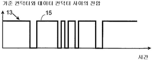
도 3은 도 1과 도 2에 나타낸 시스템에 의해 구비되는 기능 모듈 사이의 통신 신호의 그래프로서, 고주파 펄스를 강조해서 나타낸 것이고,
도 4는 도 1과 도 2에 나타낸 시스템에 의해 구비되는 기능 모듈 사이의 통신 신호의 그래프로서, 단지 도 3에 나타낸 고주파 펄스에 의해 형성되는 포락선(envelope)을 강조해서 나타낸 것이다.The invention is now described in more detail on the basis of the drawings:
1 shows a block diagram of a communication system for an electronic device of the present invention,
2 shows a simplified electrical scheme of a communication system for an electronic device of the present invention,
3 is a graph of communication signals between the functional modules provided by the system shown in FIGS. 1 and 2, with emphasis on high frequency pulses;
FIG. 4 is a graph of the communication signals between the functional modules provided by the system shown in FIGS. 1 and 2, with emphasis only on the envelope formed by the high frequency pulses shown in FIG. 3.
전자 장치를 위한 통신 시스템(장비 또는 어플라이언스), 본 발명의 목적은, 도 1에 개략적으로 나타내어져 있다.A communication system (equipment or appliance) for an electronic device, the object of the invention is schematically shown in FIG.
상기 시스템은, 적어도 하나의 기능 모듈(1, 2, 3, 4)이 처리 장치(5)를 가진 복수의 기능 모듈(1, 2, 3, 4)을 구비하고 있다. 추가적으로, 적어도 하나의 기능 모듈(1, 2, 3, 4)은 센서(6) 또는 미리 정해진 임피던스를 갖는 부하(7)로 이루어진 제어가능한 장치(6, 7)를 갖고 있다. 처리 장치(5)는 어떤 기능 모듈(1, 2, 3, 4)에 배치될 수 있는 적어도 하나의 제어가능한 장치(6, 7)를 제어할 수 있는 프로그램가능한 마이크로 컨트롤러 또는 마이크로 프로세서로 구성되는 것이 바람직하다. 바람직하게는, 상기 시스템은 복수의 처리 장치(5)와 제어가능한 장치(6, 7)를 구비하고 있다. 추가적으로, 상기 시스템은 또한 미리 정해진 주파수에서 기능 모듈(1, 2, 3, 4)에 교류 전압을 공급하도록 배열된 전기 에너지 공급 장치(소스; 8)를 구비하고 있다. 일반적으로, 이 공급 전압의 신호의 주파수는 전자 장비의 설치 사이트에 따라 50Hz와 60Hz 사이에서 달라진다. 분명히, 진폭(magnitude)의 이러한 단위에서 다른 주파수 값이 국부적인 설치 조건 및 장비의 응용 분야에 따라 사용될 수 있다.The system comprises a plurality of
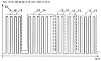
기능 모듈(1, 2, 3, 4)은, 전기 에너지 공급 장치(8)를 상기 기능 모듈(1, 2, 3, 4)에 전기적으로 연결하도록 차례로 배열되어 있는 적어도 하나의 전원 버스(power bus; 9, 10)에 의해 서로 전기적으로 연결되어 있다. 따라서, 전원 버스(9, 10)는 전기 에너지 공급 장치(8)의 전류를 기능 모듈(1, 2, 3, 4)로 전도하는 것을 담당한다. 전원 버스(9, 10)는 위상 컨덕터(phase conductor; 9) 및 기준 컨덕터(reference conductor; 10)를 구비하고 있다. 바람직하게는, 이 시스템은 추가 기능 모듈(확장성)의 구현을 간단화하고 촉진하는 것 외에, 비용을 절감하고 그 성능을 최적화하기 위해 단일의 전원 버스(9, 10)를 구비하고 있다. 추가적으로, 기능 모듈(1, 2, 3, 4)은 또한 이들 기능 모듈(1, 2, 3, 4)이 서로 병렬 연결(parallel association)을 허용하도록 배열된 통신 버스(11)를 매개로 서로 동작가능하게 연결된다. 통신 버스(11, 10)는 데이터 컨덕터(11) 및 기준 컨덕터(10)를 구비하고 있다. 바람직하게는, 이 시스템은 또한 추가 기능 모듈(확장성)의 구현을 간단화하고 촉진하는 것 외에, 비용을 절감하고 그 성능을 최적화하기 위해 단일의 통신 버스(11, 10)를 구비하고 있다.The
따라서, 그 시스템에 부하 또는 추가적인 센서를 구현할 필요가 있을 때는, 단지 부하 유형 또는 센서 유형의 장치를 전원 버스(9, 10) 및 통신 버스(11, 10)에 연결하고, 이들 추가적인 구성요소가 시스템에 적절하고 통합된 방식으로 동작할 수 있도록 적절한 매개 변수 및 명령과 함께 시스템 가동(behavior)을 제어하는 프로그램을 제공하는 것이 필요하게 된다.Thus, when a load or additional sensor needs to be implemented in the system, only a device of the load type or sensor type is connected to the
이러한 의미에서, 다른 복잡도(degrees of complexity), 다른 수의 부하 및 센서를 갖는 장치/시스템은 새로운 특정의 전자 제어 설계를 위한 필요성 없이 이 발명에서 제안된 솔루션에 의해 제어될 수 있다.In this sense, devices / systems with different degrees of complexity, different numbers of loads and sensors can be controlled by the solution proposed in this invention without the need for new specific electronic control designs.
기준 컨덕터(10)가 전원 버스(9, 10) 및 통신 버스(11, 10)에 의해 공유된다는 것이 중요하다. 도 1에 나타낸 본 발명의 바람직한 실시예에서는, 전자 장비가 4개의 기능 모듈(1, 2, 3, 4), 즉It is important that the
- 시스템의 중앙 모니터링 및 제어 장치로 구성되고, 어느 기능 모듈(2, 3, 4)이 동작을 실행하고 데이텀(datum, 자료)을 다른 기능 모듈(1, 2, 3, 4)로 송신해야 하는지를 지시하기 위해 정보 패키지가 통신 버스(11, 10)에 인가되는 순간을 주기적으로 표시할 수 있으며, 상기 기능이 처리 장치(5)의 동작에 의해 가능하게 되는 주요 기능 모듈(1);A central monitoring and control unit of the system, which function modules (2, 3, 4) perform the operation and transmit the datum (data) to the other function modules (1, 2, 3, 4); A main function module (1) which can periodically indicate the moment when the information package is applied to the communication buses (11, 10) for indication, the function being made possible by the operation of the processing apparatus (5);
- 적어도 벤틸레이터(ventilator, 환기장치), 램프, 전기 저항, 전자 기계 액추에이터 및 그 중에서 하나로 구성될 수 있는 부하(7)를 갖추고, 바람직하게는 처리 장치(5)도 갖춘 기능 작동 모듈(functional actuation module; 2);A functional actuation module having at least a ventilator, a lamp, an electric resistance, an electromechanical actuator and a load 7 which can be composed of one of them, preferably also a
- 적어도 온도 게이지, 압력 게이지, 진동 또는 음향 압력 게이지, 근접 센서, 및 그 중에서 하나로 구성될 수 있는 센서(6)를 갖추고, 바람직하게는 처리 장치(5)도 갖춘 기능 측정 모듈(functional measuring module; 3); 및A functional measuring module with at least a temperature gauge, a pressure gauge, a vibrating or acoustic pressure gauge, a proximity sensor, and a sensor 6 which can be composed of one of them, preferably also with a
- 유지 보수/시험 및/또는 원격 제어 작업을 위한 인터넷, 적외선, 블루투스, 지그비(Zigbee), 와이파이 또는 이동 전화 네트워크를 매개로 한 외부 장비와의 로컬 접속(local connection) 또는 원격 접속(remote connection)을 가능하게 하기 위해, 전자 장비와 적어도 모니터링하는 수단 사이의 작동되는 상호작용(operative interaction) 및/또는 외부 제어를 허용하도록 배열된 기능 인터페이스 모듈(4)Local or remote connection with external devices via the Internet, infrared, Bluetooth, Zigbee, Wi-Fi or mobile phone networks for maintenance / testing and / or remote control tasks. Functional interface module 4 arranged to allow operative interaction and / or external control between the electronic equipment and at least the means for monitoring
을 구비하고 있다.Equipped with.
따라서, 주요 기능 모듈(1)은, 어떤 다른 기능 모듈(2, 3, 4)이 예를 들어 전력이 전원 버스(9, 10)로부터 부하(7)로 흘러야 하는 순간과 같은 정해진 동작을 실행해야 하는 순간, 또는 기능 측정 모듈(3)이 센서(6)에서 측정된 진폭값을 알려야 하는 순간 또는 기능 인터페이스 모듈(4)이 정보를 요청하고 통신 버스(11, 10)를 경유해서 다른 외부 장치로부터 입력되는 정보를 공급해야 하는 순간을 앞서 자세히 설명한 적절한 전압 신호에 의해 주기적으로 지시한다.Thus, the main functional module 1 must perform certain operations such as the moment when some other
도 2에서 알 수 있는 바와 같이, 상기 시스템은 또한 전기 에너지 공급 장치(8)와 기능 모듈(1, 2, 3, 4) 사이에 배치되어 전기 에너지 공급 장치(8)의 전압 주파수보다 실질적으로 큰 주파수를 갖는 전기 신호의 성분만의 통과를 허용할 수 있는 주파수 필터(12)도 구비하고 있다. 따라서, 주파수 필터(12)는 전원 버스(9, 10)에서 발생할 수 있는 서지에 대해, 기능 모듈(1, 2, 3, 4)과 그들의 구성요소 및 예를 들어 제어가능한 장치(6, 7)와 같은 내부 요소(internal element)를 간접적으로 보호하는 기능을 가진다. 본 발명의 바람직한 실시예에 따르면, 주파수 필터(12)는 전기 에너지 공급 장치(8)의 전압 주파수보다 큰 주파수를 갖는 전기 신호의 성분만의 통과를 허용할 수 있는 특정값을 갖는 디커플링 캐패시터(decoupling capacitor, 감결합 콘덴서)로 구성된다. 주파수 필터(12)는, 회로의 전류를 제한하도록 크기가 조정된 저항(16)에 연결되어 각 기능 모듈(1, 2, 3, 4)의 구성요소와 내부 요소의 손상을 회피한다.As can be seen in FIG. 2, the system is also arranged between the
따라서, 기능 모듈(1, 2, 3, 4)간의 통신은 전력 소스(electrical power source)로부터 입력되는 전압 피크(서지)로서 그러한 높은 전압 레벨의 격리를 허용하도록 적절하게 크기가 조정된 주파수 필터(12; 디커플링 캐패시터)를 통과해야한다. 따라서, 전원 버스(9, 10)에 대한 연결이 실패한 경우에는, 필터(12)를 통해 순환하는 전류가 비교적 낮기 때문에, 기능 모듈(1, 2, 3, 4)의 요소 및 구성요소가 서지에 의해 손상되지 않게 되어 기능 모듈(1, 2, 3, 4)에 대해 어떤 유형의 손상도 회피한다. 위상 컨덕터(9)의 중단의 경우에 있어서, 상기 손상은 데이터 컨덕터(11)에 연결된 전자 회로에서 발생할 것이고, 기준 컨덕터(10)와 데이터 컨덕터(11) 사이의 전압 레벨은 접속된 부하(7) 또는 센서(6)의 어느 것인가를 통한 전류 전도로 인해 전기 에너지 공급 장치(8)에 의해 공급되는 것에 가깝거나 그와 같은 값(일반적으로 5볼트의 단위)으로 상승하도록 강요될 것이다.Thus, the communication between the
기능 모듈(1, 2, 3, 4) 사이의 통신 방법에 관해서는, 서로 기능 모듈(1, 2, 3, 4)의 작동되는 상호작용(operative interaction)을 허용하기 위해 그 프로그래밍을 통해 처리 장치(5)가 적어도 통신 신호(13)를 통신 버스(11, 10)로 공급하도록 배열되어 있다. 보다 구체적으로는, 처리 장치(5)는 통신 신호(13)를 다른 기능 모듈(1, 2, 3, 4)로 보내도록 배열된 데이터 출력 단자(19)를 갖추고 있다. 추가적으로, 처리 장치(5)는 통신 신호(13)를 다른 기능 모듈(1, 2, 3, 4)로부터 수신하도록 배열된 데이터 입력 단자(20)를 갖추고 있다.As for the communication method between the
도 3에서 알 수 있는 바와 같이, 통신 신호(13)는 전기 에너지 공급 장치에 의해 공급되는 전압의 주파수보다 실질적으로 큰 미리 정해진 반복 주파수에서 반복되도록 배열된 고주파 펄스(14)의 복수의 세트로 구성되고, 여기서 상기 고주파 펄스의 반복 주파수의 값은 실질적으로는 60Hz보다 큰 값, 바람직하게는 kHz?MHz의 단위로 이루어진다.As can be seen in FIG. 3, the
고주파 펄스(14)의 각 세트는 미리 수립된 통신 프로토콜의 적어도 하나의 비트에 대응하는 정보 펄스(15)를 형성하도록(어떤 모양으로 만들도록) 배열되어 있고, 여기서 정보 펄스(15)는 결정된 기능 모듈(1, 2, 3, 4)이 다른 기능 모듈(1, 2, 3, 4)로 보내는 데이텀(비트)으로 유효하게 이루어진다. 정보 비트의 세트는 앞서 언급한 통신 프로토콜을 따르는 정보 패키지를 형성한다는 것이 중요하다.Each set of
도 3에 있어서, 정보 펄스(15)는 그래프 상의 실선 곡선(continuous line curve)으로 표시된 고주파 펄스(14)를 외면적으로 포함하는 점선 곡선(dotted line curve)으로 이루어진다. 도 4는 처리 장치(5)에 의해 실행되는 프로그램에 의해 수립된 미리 정해진 특정 통신 프로토콜을 따르는 정보 펄스(15)의 예를 나타낸 것이다.In Fig. 3, the
이런 이유로, 정보 패키지를 형성하는 정보 펄스(15)는 데이터 컨덕터(11)와 기준 컨덕터(10) 사이에 가해진 전압 변조에 의해 형성된다. 이 변조는, 정보 패키지를 형성하는 디지털 펄스(전압 포락선)로부터의 구별을 명백하게 허용하기 위해 충분히 높은 주파수의 최대 및 최소 레벨 사이의 전압의 변동으로 이루어진다.For this reason, the
따라서, 적어도 2개의 기능 모듈(1, 2, 3, 4) 사이의 상호작용은, 처리 장치(5)에 의해 실행되는 프로그램(소프트웨어)을 통해 제어되는 고주파 펄스(14)로 구성된 순차적인 전압 포락선(정보 펄스(15))에 의해 인에이블(enable)되는 교환이나 그들 사이의 양방향 디지털 정보 흐름을 허용한다.Thus, the interaction between at least two
도 2에 따르면, 하드웨어에 관해서는, 기능 모듈(1, 2, 3, 4)은 전압 포락선의 정보를 허용하기 위해 통신 신호(13)를 지원하도록 서로 결합된 캐패시터(21) 와 저항(22)을 갖고 있다. 추가적으로, 기능 모듈(1, 2, 3, 4)은 통신 신호(13)의 데이터 입력 단자(20)로의 공급을 허용할 수 있는 한 세트의 정류 다이오드(23, 24)도 갖추고 있다.According to FIG. 2, in terms of hardware, the
또한 도 2에서 알 수 있는 바와 같이, 기능 모듈(1, 2, 3, 4)은 그 구성요소 및 내부 요소에 전기적으로 전력을 공급할 수 있는 연속적인 전압 소스(18)를 구비하고 있다. 이 연속적인 전압 소스(18)는 차례로 통신 신호(13) 자체 및/또는 전기 에너지 공급 장치(8)로부터 입력되는 교류 주전압의 정류된 전기 신호에 의해 전력이 공급될 수 있다.As can also be seen in FIG. 2, the
따라서, 본 발명에 의해 드러난 시스템의 하드웨어-소프트웨어 조합이 통신 신호(13)의 형성뿐만 아니라 서로에 대해 기능 모듈(1, 2, 3, 4)의 작동되는 상호작용을 허용한다.Thus, the hardware-software combination of the system revealed by the present invention allows the formation of the
위에서 설명한 시스템에 의해 실행되는 통신의 방법도 또한 본 발명의 보호의 대상이며, 다음과 같은 단계: i) 단일의 통신 버스(11, 10)를 매개로 서로 동작가능하게 기능 모듈(1, 2, 3, 4)을 연결하는 단계; ii) 전기 에너지 공급 장치(8)의 전압 주파수보다 실질적으로 큰 미리 정해진 반복 주파수에서 반복하는 고주파 펄스(14)를 통신 버스(11, 10)에 공급하는 단계; iii) 단계 ii)에서 공급된 고주파 펄스(14)를 복수의 정보 펄스(15)를 형성하도록 세트로 배열하는 단계; iv) 단계 iii)에서 형성된 정보 펄스(15)를 통신 신호(13)를 형성하도록 세트로 배열하는 단계; v) 전기 에너지 공급 장치(8)의 전압 주파수보다 낮거나 그 주파수와 같은 통신 신호(13)의 주파수 성분을 통과시키도록 필터링하는 단계를 구비한다.The method of communication carried out by the system described above is also subject to the protection of the present invention, the following steps: i)
기존의 통신 시스템 및 방법에서는, 고주파 펄스가 전압 포락선 자체(정보 펄스(15))로 구성된다는 점, 즉 각 전압 펄스가 송신하기를 원하는 사용자에게 비트 자체(정보)를 나타내도록 전압 포락선이 고주파에서 반복하도록 배열된 고주파 펄스를 갖추지 않는다는 점을 강조하는 것이 중요하다. 따라서, 기존의 통신 시스템에서는, 분명히 바람직하지 않은 정보 데이터(비트)를 필터링할 수 있는 것처럼 주파수 필터를 구현하는 것은 불가능하다. 예를 들어, 전원 버스의 위상 컨덕터에 접촉 장애 또는 연속성 손실이 있는 경우는, 여전히 전원 공급 장치에 연결된 모든 기능 모듈에 있어서 위상 컨덕터(9)와 기준 컨덕터(10) 사이에 높은 전압(예를 들어 110V 또는 220V)이 발생되는데, 시스템이 면역 능력을 갖고 있기 않기 때문에, 이 고전압에 의해 그 구성요소 및 내부 요소가 손상될 수 있다.In conventional communication systems and methods, a high frequency pulse is composed of a voltage envelope itself (information pulse 15), i.e., the voltage envelope at high frequency such that each voltage pulse represents the bit itself (information) to the user wishing to transmit. It is important to emphasize that it does not have high frequency pulses arranged to repeat. Therefore, in existing communication systems, it is impossible to implement a frequency filter as it can filter out undesirable information data (bits). For example, if there is a contact failure or loss of continuity in the phase conductors of the power bus, a high voltage (e.g., between the phase conductor 9 and the
그에 반해, 본 발명의 시스템의 중요한 특징은 주파수 필터(12)의 존재로 인해 전원 버스에서의 임의의 설치 실패와 접촉 결함에 대해 그 면역성이 있다는 점이고, 이러한 특징은 이전에 설명한 바와 같이 기능 모듈(1, 2, 3, 4) 사이의 통신(정보 흐름)은 고주파 펄스에 의한 것이기 때문에, 그 정확한 작업을 구비하는 일없이 시스템에 있어서 적절히 구현될 수 있다.On the contrary, an important feature of the system of the present invention is that it is immune to any installation failures and contact faults in the power bus due to the presence of the
따라서, 본 발명은 로컬 및/또는 원격 장비에 의한 모니터링/외부 제어를 가능하게 할 뿐만 아니라 그 모듈러(modular) 및 확장성 수용능력과 관련된 상기 면역 특성을 전례 없는 방식으로 공급한다.Thus, the present invention not only enables monitoring / external control by local and / or remote equipment, but also provides the immune characteristics related to its modular and expandable capacity in an unprecedented manner.
예시적인 바람직한 실시예를 설명했는데, 본 발명의 범위는 여기에 첨부된 청구의 범위의 내용에 의해서만 한정되는 다른 가능한 변형을 포함하고, 잠재적인 등가물은 그 안에 포함됨을 이해해야 한다.Having described exemplary preferred embodiments, it is to be understood that the scope of the present invention includes other possible modifications limited only by the content of the claims appended hereto, and potential equivalents are included therein.
Claims (8)
- 미리 정해진 주파수에서 상기 기능 모듈(1, 2, 3, 4)에 교류 전압을 공급하도록 배열된 적어도 하나의 전기 에너지 공급 장치(8);
- 상기 전기 에너지 공급 장치(8)를 상기 기능 모듈(1, 2, 3, 4)에 전기적으로 연결하도록 배열된 적어도 하나의 전원 버스(9, 10);
- 상기 기능 모듈(1, 2, 3, 4)을 서로 병렬로 동작가능하게 연결하도록 배열된 적어도 하나의 통신 버스(11, 10);
- 상기 전기 에너지 공급 장치와 상기 기능 모듈(1, 2, 3, 4) 사이에 배치되어 상기 전기 에너지 공급 장치 전압 주파수보다 큰 전기 신호의 주파수 성분의 통과만을 허용할 수 있는 주파수 필터(12)를 구비하여 구성되되,
상기 처리 장치(5)는 적어도 하나의 통신 신호(13)를 통신 버스(11, 10)에 공급하도록 배열되고, 상기 통신 신호(13)는 상기 기능 모듈(1, 2, 3, 4) 사이에서 작동되는 상호작용을 허용할 수 있으며, 상기 통신 신호(13)는 고주파 펄스(14)의 복수의 세트로 구성되고, 상기 고주파 펄스(14)는 미리 정해진 반복 주파수에서 반복되도록 배열되며, 상기 반복 주파수는 상기 전기 에너지 공급 장치에 의해 공급되는 전압의 주파수보다 실질적으로 크고, 고주파 펄스(14)의 각 세트는 통신 프로토콜의 적어도 하나의 비트에 대응하는 정보 펄스(15)를 형성하도록 배열된 것을 특징으로 하는 전자 장치를 위한 통신 시스템.
At least one functional module (1, 2, 3, 4) has a processing device and at least one functional module (1, 2, 3, 4) is controllable by the processing device (5) A plurality of function modules (1, 2, 3, 4) having;
At least one electrical energy supply (8) arranged to supply an alternating voltage to the function module (1, 2, 3, 4) at a predetermined frequency;
At least one power bus (9, 10) arranged to electrically connect the electrical energy supply (8) to the functional module (1, 2, 3, 4);
At least one communication bus (11, 10) arranged to operatively connect said functional modules (1, 2, 3, 4) in parallel with each other;
A frequency filter 12 disposed between the electrical energy supply and the functional modules 1, 2, 3, 4, which can only allow passage of frequency components of an electrical signal greater than the electrical energy supply voltage frequency. Equipped and configured,
The processing device 5 is arranged to supply at least one communication signal 13 to the communication buses 11, 10, the communication signal 13 being between the function modules 1, 2, 3, 4. Allow for interaction to be activated, the communication signal 13 consisting of a plurality of sets of high frequency pulses 14, the high frequency pulses 14 arranged to be repeated at a predetermined repetition frequency, the repetition frequency Is substantially greater than the frequency of the voltage supplied by the electrical energy supply, and each set of high frequency pulses 14 is arranged to form an information pulse 15 corresponding to at least one bit of the communication protocol. Communication system for an electronic device.
2. Communication system according to claim 1, characterized in that the device (6, 7) controllable by the processing device (5) consists of a sensor (6) or a load (7).
The device according to one of the preceding claims, characterized in that it comprises a single power bus (9, 10) arranged to electrically connect the electrical energy supply (8) to the functional module (1, 2, 3, 4). Communication system.
Communication system according to one of the preceding claims, characterized in that it comprises a single communication bus (11, 10) arranged to operatively connect said functional modules (1, 2, 3, 4) to each other.
The method according to any one of the preceding claims, characterized in that the frequency filter (12) consists of a decoupling capacitor having a specific value that can allow passage of only components of an electrical signal having a frequency greater than the electrical energy supply voltage frequency. Communication system.
The functional interface module according to any one of the preceding claims, wherein the functional modules 1, 2, 3, 4 are arranged to allow for an operative interaction between the electronic device and at least one means of monitoring and / or external control. (4) a communication system characterized by the above-mentioned.
In any one of the preceding claims, the functional module (1, 2, 3, 4) is provided with a continuous voltage source (18) capable of electrically supplying its components and internal elements, and said continuous An exemplary voltage source (18) is characterized in that the power is supplied by the rectified electrical signal of an alternating voltage input from the communication signal (13) itself and / or from the electrical energy supply (8).
i) 단일의 통신 버스(11, 10)를 매개로 서로 동작가능하게 기능 모듈(1, 2, 3, 4)을 연결하는 단계;
ii) 전기 에너지 공급 장치 전압 주파수보다 실질적으로 큰 미리 정해진 반복 주파수에서 반복하는 복수의 고주파 펄스(14)를 통신 버스(11, 10)에 공급하는 단계;
iii) 단계 ii)에서 공급된 고주파 펄스(14)를 복수의 정보 펄스(15)를 형성하도록 세트로 배열하는 단계;
iv) 단계 iii)에서 형성된 정보 펄스(15)를 통신 신호(13)를 형성하도록 세트로 배열하는 단계; 및
v) 전기 에너지 공급 장치 전압 주파수보다 낮거나 그 주파수와 같은 통신 신호(13)의 주파수 성분을 통과시키도록 필터링하는 단계를 구비하는 것을 특징으로 하는 통신 방법.
The electronic device has functional modules 1, 2, 3, 4 electrically connected to each other by a single power bus 9, 10, which power buses 9, 10 are connected to an electrical energy supply 8. The electrical energy supply device 8 is electrically connected and the communication method for an electronic device arranged to supply an alternating voltage to the functional modules 1, 2, 3, 4 at a predetermined frequency, the method comprising: ,
i) connecting the functional modules (1, 2, 3, 4) to be operative to each other via a single communication bus (11, 10);
ii) supplying a communication bus (11, 10) with a plurality of high frequency pulses (14) which repeat at a predetermined repetition frequency substantially greater than the electrical energy supply voltage frequency;
iii) arranging the high frequency pulses 14 supplied in step ii) in sets to form a plurality of information pulses 15;
iv) arranging the information pulses 15 formed in step iii) in a set to form a communication signal 13; And
v) filtering to pass a frequency component of the communication signal (13) below or equal to the electrical energy supply voltage frequency.
Applications Claiming Priority (2)
| Application Number | Priority Date | Filing Date | Title |
|---|---|---|---|
| BRPI0901496-9 | 2009-05-15 | ||
| BRPI0901496-9A BRPI0901496A2 (en) | 2009-05-15 | 2009-05-15 | communication system and method for electronic equipment |
Publications (1)
| Publication Number | Publication Date |
|---|---|
| KR20120041176A true KR20120041176A (en) | 2012-04-30 |
Family
ID=42333315
Family Applications (1)
| Application Number | Title | Priority Date | Filing Date |
|---|---|---|---|
| KR1020117029603A KR20120041176A (en) | 2009-05-15 | 2010-05-12 | System and method of communication for electronic apparatuses |
Country Status (9)
| Country | Link |
|---|---|
| US (1) | US9176494B2 (en) |
| EP (1) | EP2430501B1 (en) |
| JP (2) | JP2012527132A (en) |
| KR (1) | KR20120041176A (en) |
| CN (1) | CN101895452B (en) |
| AR (1) | AR077170A1 (en) |
| BR (1) | BRPI0901496A2 (en) |
| SG (1) | SG176065A1 (en) |
| WO (1) | WO2010130018A1 (en) |
Families Citing this family (2)
| Publication number | Priority date | Publication date | Assignee | Title |
|---|---|---|---|---|
| WO2020149855A1 (en) * | 2019-01-18 | 2020-07-23 | Hewlett-Packard Development Company, L.P. | Print cartridge circuits |
| JP7032366B2 (en) * | 2019-10-09 | 2022-03-08 | 株式会社日立製作所 | Operations support system and method |
Family Cites Families (15)
| Publication number | Priority date | Publication date | Assignee | Title |
|---|---|---|---|---|
| JPS5755341A (en) * | 1980-09-22 | 1982-04-02 | Mitsubishi Electric Corp | Control system for air conditioning machine |
| JPH07177362A (en) * | 1993-01-08 | 1995-07-14 | Canon Inc | Image processing system and image processor |
| JP3091620B2 (en) * | 1993-12-27 | 2000-09-25 | 戸田建設株式会社 | Guidance light control system |
| JP3379226B2 (en) * | 1994-07-25 | 2003-02-24 | 三菱電機株式会社 | Control device for air conditioner |
| US5600310A (en) * | 1994-12-02 | 1997-02-04 | General Electric Company | Serial bus control for appliances |
| US6683531B2 (en) * | 2000-05-04 | 2004-01-27 | Trench Limited | Coupling device for providing a communications link for RF broadband data signals to a power line and method for installing same |
| US7136270B2 (en) * | 2003-01-28 | 2006-11-14 | Gateway Inc. | Surge protector including data pass-through |
| JP4336142B2 (en) * | 2003-05-23 | 2009-09-30 | 日立アプライアンス株式会社 | Air conditioner communication control device |
| ES2424149T3 (en) * | 2003-10-21 | 2013-09-27 | Panasonic Corporation | Communications circuit between building equipment |
| JP4725119B2 (en) * | 2004-02-10 | 2011-07-13 | 株式会社富士通ゼネラル | Air conditioner control device |
| JP4419592B2 (en) * | 2004-02-10 | 2010-02-24 | 株式会社富士通ゼネラル | Air conditioner control device |
| BRPI0402015A (en) | 2004-05-05 | 2005-12-20 | Brasil Compressores Sa | System and process for energizing loads by a control unit |
| JP2009079811A (en) * | 2007-09-26 | 2009-04-16 | Sanyo Electric Co Ltd | Air conditioning system and indoor unit |
| JP5340574B2 (en) * | 2007-09-26 | 2013-11-13 | 三洋電機株式会社 | Air conditioning system and communication control device |
| NZ563174A (en) * | 2007-11-05 | 2010-03-26 | Gang Chen | Method and apparatus for remotely controlling electrically powered accessories by way of a digital signal impressed onto the power cable of the accessory to be controlled |
-
2009
- 2009-05-15 BR BRPI0901496-9A patent/BRPI0901496A2/en active Search and Examination
-
2010
- 2010-05-12 EP EP10720524.7A patent/EP2430501B1/en not_active Not-in-force
- 2010-05-12 AR ARP100101641A patent/AR077170A1/en active IP Right Grant
- 2010-05-12 US US13/320,647 patent/US9176494B2/en not_active Expired - Fee Related
- 2010-05-12 SG SG2011083896A patent/SG176065A1/en unknown
- 2010-05-12 WO PCT/BR2010/000152 patent/WO2010130018A1/en active Application Filing
- 2010-05-12 JP JP2012510074A patent/JP2012527132A/en active Pending
- 2010-05-12 KR KR1020117029603A patent/KR20120041176A/en not_active Application Discontinuation
- 2010-05-14 CN CN201010225749.8A patent/CN101895452B/en not_active Expired - Fee Related
-
2014
- 2014-12-26 JP JP2014266510A patent/JP2015065698A/en not_active Ceased
Also Published As
| Publication number | Publication date |
|---|---|
| CN101895452B (en) | 2014-08-13 |
| EP2430501B1 (en) | 2013-04-17 |
| EP2430501A1 (en) | 2012-03-21 |
| AR077170A1 (en) | 2011-08-10 |
| US9176494B2 (en) | 2015-11-03 |
| US20120158194A1 (en) | 2012-06-21 |
| SG176065A1 (en) | 2011-12-29 |
| CN101895452A (en) | 2010-11-24 |
| JP2012527132A (en) | 2012-11-01 |
| WO2010130018A1 (en) | 2010-11-18 |
| BRPI0901496A2 (en) | 2011-01-18 |
| JP2015065698A (en) | 2015-04-09 |
Similar Documents
| Publication | Publication Date | Title |
|---|---|---|
| JP3686443B2 (en) | Device and method for manipulating the power status of a remote device | |
| US11664677B2 (en) | Intelligent automatic transfer switch module | |
| US8230083B2 (en) | Communication adapter apparatus, communication adapter, method of writing data in nonvolatile memory, and electric apparatus and ROM writer used for the method | |
| CN101907689B (en) | Generation method and device of test circuit and power supply testing system | |
| JP3693337B2 (en) | Power system wiring diagram creation system, and power supply equipment and program used therefor | |
| CN105981127A (en) | Relay with integral phase controlled switching | |
| US10075015B2 (en) | Maintenance transfer switch | |
| CN102680829B (en) | Device and method for monitoring safe failure of electric device | |
| RU2604332C2 (en) | Wireless field device having reconfigurable discrete input/output channel | |
| US9989593B2 (en) | Modular test environment for a plurality of test objects | |
| CN104850474B (en) | A kind of hard disc of computer batch-testing device and test method | |
| KR20120041176A (en) | System and method of communication for electronic apparatuses | |
| CN117246178A (en) | DC charging pile power distribution one-in four-out switch module device and control method | |
| RU2724183C1 (en) | Automation technology field device based on energy technology via ethernet | |
| CN201514450U (en) | Drawer module testing device and drawer module testing system | |
| US20070255969A1 (en) | Device for Controlling the Energy Flow Between an Energy Supply Network and an Electric Device Connected Thereto | |
| CN201266352Y (en) | Power source remote controller for computer | |
| JP4828524B2 (en) | System and method for applying a voltage to a load via a control unit | |
| CN211918407U (en) | One-inlet four-outlet switch module device for power distribution of direct current charging pile | |
| CN107357203A (en) | A kind of high-low voltage continuous monitoring device | |
| JP3553481B2 (en) | measuring device | |
| US20150142197A1 (en) | Automated identification of components connected in a power grid | |
| CN110311618A (en) | Electric machine control system | |
| CN107742808A (en) | Electric power connection line | |
| CN204304408U (en) | A kind of motor controlling protector |
Legal Events
| Date | Code | Title | Description |
|---|---|---|---|
| A201 | Request for examination | ||
| E902 | Notification of reason for refusal | ||
| E601 | Decision to refuse application |