KR20120016260A - Methods for making microreplication tools - Google Patents
Methods for making microreplication tools Download PDFInfo
- Publication number
- KR20120016260A KR20120016260A KR1020117028804A KR20117028804A KR20120016260A KR 20120016260 A KR20120016260 A KR 20120016260A KR 1020117028804 A KR1020117028804 A KR 1020117028804A KR 20117028804 A KR20117028804 A KR 20117028804A KR 20120016260 A KR20120016260 A KR 20120016260A
- Authority
- KR
- South Korea
- Prior art keywords
- cutting
- workpiece
- tool
- distance
- cutting tool
- Prior art date
Links
Images


Classifications
-
- B—PERFORMING OPERATIONS; TRANSPORTING
- B23—MACHINE TOOLS; METAL-WORKING NOT OTHERWISE PROVIDED FOR
- B23B—TURNING; BORING
- B23B1/00—Methods for turning or working essentially requiring the use of turning-machines; Use of auxiliary equipment in connection with such methods
-
- B—PERFORMING OPERATIONS; TRANSPORTING
- B22—CASTING; POWDER METALLURGY
- B22D—CASTING OF METALS; CASTING OF OTHER SUBSTANCES BY THE SAME PROCESSES OR DEVICES
- B22D11/00—Continuous casting of metals, i.e. casting in indefinite lengths
- B22D11/06—Continuous casting of metals, i.e. casting in indefinite lengths into moulds with travelling walls, e.g. with rolls, plates, belts, caterpillars
- B22D11/0637—Accessories therefor
- B22D11/0665—Accessories therefor for treating the casting surfaces, e.g. calibrating, cleaning, dressing, preheating
- B22D11/0674—Accessories therefor for treating the casting surfaces, e.g. calibrating, cleaning, dressing, preheating for machining
-
- B—PERFORMING OPERATIONS; TRANSPORTING
- B23—MACHINE TOOLS; METAL-WORKING NOT OTHERWISE PROVIDED FOR
- B23B—TURNING; BORING
- B23B27/00—Tools for turning or boring machines; Tools of a similar kind in general; Accessories therefor
- B23B27/14—Cutting tools of which the bits or tips or cutting inserts are of special material
- B23B27/18—Cutting tools of which the bits or tips or cutting inserts are of special material with cutting bits or tips or cutting inserts rigidly mounted, e.g. by brazing
- B23B27/20—Cutting tools of which the bits or tips or cutting inserts are of special material with cutting bits or tips or cutting inserts rigidly mounted, e.g. by brazing with diamond bits or cutting inserts
-
- B—PERFORMING OPERATIONS; TRANSPORTING
- B23—MACHINE TOOLS; METAL-WORKING NOT OTHERWISE PROVIDED FOR
- B23B—TURNING; BORING
- B23B5/00—Turning-machines or devices specially adapted for particular work; Accessories specially adapted therefor
- B23B5/36—Turning-machines or devices specially adapted for particular work; Accessories specially adapted therefor for turning specially-shaped surfaces by making use of relative movement of the tool and work produced by geometrical mechanisms, i.e. forming-lathes
- B23B5/46—Turning-machines or devices specially adapted for particular work; Accessories specially adapted therefor for turning specially-shaped surfaces by making use of relative movement of the tool and work produced by geometrical mechanisms, i.e. forming-lathes for turning helical or spiral surfaces
- B23B5/48—Turning-machines or devices specially adapted for particular work; Accessories specially adapted therefor for turning specially-shaped surfaces by making use of relative movement of the tool and work produced by geometrical mechanisms, i.e. forming-lathes for turning helical or spiral surfaces for cutting grooves, e.g. oil grooves of helicoidal shape
-
- B—PERFORMING OPERATIONS; TRANSPORTING
- B23—MACHINE TOOLS; METAL-WORKING NOT OTHERWISE PROVIDED FOR
- B23B—TURNING; BORING
- B23B2210/00—Details of turning tools
- B23B2210/02—Tool holders having multiple cutting inserts
- B23B2210/022—Grooving tools
-
- B—PERFORMING OPERATIONS; TRANSPORTING
- B23—MACHINE TOOLS; METAL-WORKING NOT OTHERWISE PROVIDED FOR
- B23B—TURNING; BORING
- B23B2270/00—Details of turning, boring or drilling machines, processes or tools not otherwise provided for
- B23B2270/16—Constructions comprising three or more similar components
-
- Y—GENERAL TAGGING OF NEW TECHNOLOGICAL DEVELOPMENTS; GENERAL TAGGING OF CROSS-SECTIONAL TECHNOLOGIES SPANNING OVER SEVERAL SECTIONS OF THE IPC; TECHNICAL SUBJECTS COVERED BY FORMER USPC CROSS-REFERENCE ART COLLECTIONS [XRACs] AND DIGESTS
- Y10—TECHNICAL SUBJECTS COVERED BY FORMER USPC
- Y10T—TECHNICAL SUBJECTS COVERED BY FORMER US CLASSIFICATION
- Y10T428/00—Stock material or miscellaneous articles
- Y10T428/24—Structurally defined web or sheet [e.g., overall dimension, etc.]
- Y10T428/24479—Structurally defined web or sheet [e.g., overall dimension, etc.] including variation in thickness
- Y10T428/2457—Parallel ribs and/or grooves
- Y10T428/24587—Oblique to longitudinal axis of web or sheet
-
- Y—GENERAL TAGGING OF NEW TECHNOLOGICAL DEVELOPMENTS; GENERAL TAGGING OF CROSS-SECTIONAL TECHNOLOGIES SPANNING OVER SEVERAL SECTIONS OF THE IPC; TECHNICAL SUBJECTS COVERED BY FORMER USPC CROSS-REFERENCE ART COLLECTIONS [XRACs] AND DIGESTS
- Y10—TECHNICAL SUBJECTS COVERED BY FORMER USPC
- Y10T—TECHNICAL SUBJECTS COVERED BY FORMER US CLASSIFICATION
- Y10T82/00—Turning
- Y10T82/10—Process of turning
Abstract
피치 간격 P만큼 분리된 인접 특징부(52, 53)들을 포함하는 패턴을 공작물(50) 내에 절삭하기 위한 방법이 제공된다. 본 방법은 공작물(50) 내에 제1 특징부(52)를 생성하는 제1 절삭 팁(22)을 갖는 제1 공구 섕크, 및 공작물(50) 내에 제2 특징부(53)를 생성하는 제2 절삭 팁(23)을 갖는 제2 공구 섕크를 구비한 절삭 공구 조립체(74)를 제공하는 단계를 포함하며, 여기서 제1 절삭 팁과 제2 절삭 팁 사이의 거리 Y는 nP와 같고, 여기서 n은 1보다 큰 홀수 정수이다. 공작물은 절삭 공구 조립체(74)에 대해서 회전되고(C), 절삭 공구는 회전하는 공작물(50)에 대해서 횡방향(B)을 따라 전진되며, 여기서 절삭 공구(74)는 공작물(50)의 각각의 회전에 대해서 2P의 거리만큼 횡방향을 따라 전진된다.A method is provided for cutting a pattern in a workpiece 50 comprising adjacent features 52, 53 separated by a pitch spacing P. The method includes a first tool shank having a first cutting tip 22 that creates a first feature 52 in a work piece 50, and a second generating a second feature 53 in a work piece 50. Providing a cutting tool assembly 74 with a second tool shank having a cutting tip 23, wherein the distance Y between the first and second cutting tips is equal to nP, where n is Odd integer greater than one. The workpiece is rotated relative to the cutting tool assembly 74 (C) and the cutting tool is advanced along the transverse direction B relative to the rotating workpiece 50, where the cutting tool 74 is each of the workpiece 50. Advance along the transverse direction by a distance of 2P for the rotation of.
Description
본 발명은 예를 들어 미세복제 공구(microreplication tool)와 같은 공작물을 기계 가공하기 위한 방법에 관한 것이다. 본 발명은 또한 예를 들어 광 지향 필름(light directing film)과 같은, 이들 공구로부터 제조될 수 있는 미세복제된 구조체에 관한 것이다.The present invention relates to a method for machining a workpiece, for example a microreplication tool. The invention also relates to microreplicated structures which can be produced from these tools, such as for example light directing films.
다이아몬드 기계 가공 기술은 주조 벨트, 주조 롤러, 사출 주형, 압출 또는 엠보싱 공구 등을 포함하는 미세복제 공구와 같은 매우 다양한 공작물을 생성하는 데 사용될 수 있다. 미세복제 공구는 통상적으로 미세복제된 구조체를 갖는 부품을 생성하기 위해 압출 공정, 사출 성형 공정, 엠보싱 공정, 주조 공정 등에 사용된다. 광 지향 필름, 연마 필름, 접착 필름, 자기 정합 프로파일(self-mating profile)을 갖는 기계식 체결구, 또는 임의의 성형된 또는 압출된 부품은 대략 1000 마이크로미터 미만의 치수를 갖는 미세복제된 구조체를 포함할 수 있다.Diamond machining techniques can be used to produce a wide variety of workpieces, such as microreplication tools, including casting belts, casting rollers, injection molds, extrusion or embossing tools, and the like. Microreplication tools are typically used in extrusion processes, injection molding processes, embossing processes, casting processes and the like to produce parts having microreplicated structures. Light directing films, abrasive films, adhesive films, mechanical fasteners with a self-mating profile, or any molded or extruded part include microreplicated structures having dimensions of less than approximately 1000 micrometers. can do.
절삭 공구 조립체를 사용하여 미세복제 공구를 생성하는 공정은 비용이 많이 들고 시간이 많이 소비될 수 있다. 본 명세서에 참고로 포함된 미국 특허 출원 공개 제2004/0045419호('419 공개 공보)는 미세복제 공구 또는 다른 공작물을 기계 가공하는 데 사용될 수 있는, 다수의 절삭 팁을 포함하는 절삭 공구 조립체를 기술하고 있다. 특히, 절삭 공구 조립체의 다수의 절삭 팁은 조립체의 단일 절삭 패스(pass) 동안에 미세복제 공구 내에 다수의 홈 또는 다른 특징부(feature)를 생성하는 데 사용될 수 있다. 다수의 절삭 팁을 갖는 절삭 공구 조립체는 단일 절삭 패스에서 다수의 특징부를 형성할 수 있고, 그러한 공구는 단일 절삭 팁을 갖는 절삭 공구 조립체보다 더욱 신속하게 더욱 복잡한 패턴을 생성하고/하거나 제조 시간을 단축시킬 수 있다. 예를 들어, 절삭 공구 조립체가 2개의 다이아몬드를 포함하는 경우, 미세복제 공구 내에 홈을 절삭하기 위해 필요한 패스의 수는 절반만큼 감소될 수 있다.The process of creating microreplication tools using the cutting tool assembly can be expensive and time consuming. US Patent Application Publication No. 2004/0045419 ('419 Publication), incorporated herein by reference, describes a cutting tool assembly comprising a plurality of cutting tips that can be used to machine microreplication tools or other workpieces. Doing. In particular, multiple cutting tips of the cutting tool assembly can be used to create multiple grooves or other features in the microreplication tool during a single cutting pass of the assembly. Cutting tool assemblies with multiple cutting tips can form multiple features in a single cutting pass, which tools produce more complex patterns and / or shorten manufacturing times more quickly than cutting tool assemblies with single cutting tips. You can. For example, if the cutting tool assembly includes two diamonds, the number of passes required to cut the grooves in the microreplication tool may be reduced by half.
절삭 팁은 미세복제 공구 내에 생성될 홈 또는 다른 특징부에 대응하도록 정밀하게 형성된다. 절삭 팁은 미세복제 공구 내에 생성될 홈들의 1피치 이상의 간격과 동일한 거리만큼 팁들이 서로 이격되도록 장착 구조체 내에 정밀하게 위치된다.The cutting tip is precisely formed to correspond to the groove or other feature to be created in the microreplication tool. The cutting tip is precisely positioned in the mounting structure such that the tips are spaced apart from each other by a distance equal to or more than one pitch of grooves to be created in the microreplication tool.
또한, 상이한 다이아몬드 팁은 미세복제 공구 내에 생성될 상이한 특징부를 한정할 수 있다. 그 경우에, 공작물 내에 2개 이상의 물리적으로 별개인 특징부를 생성하기 위해 2개의 상이한 절삭 공구 조립체를 사용하는 것이 필요하지 않다. 그러한 기술은 미세복제 공구의 품질을 개선할 수 있고, 미세복제 공구의 생성과 관련된 시간 및 비용을 감소시킬 수 있으며, 이는 이어서 궁극적인 미세복제된 물품의 생성과 관련된 비용을 효과적으로 감소시킬 수 있다.In addition, different diamond tips may define different features to be created in the microreplication tool. In that case, it is not necessary to use two different cutting tool assemblies to create two or more physically distinct features in the workpiece. Such techniques can improve the quality of microreplication tools and reduce the time and cost associated with creating microreplication tools, which in turn can effectively reduce the costs associated with the creation of the ultimate microreplicated article.
'419 공개 공보는 다수의 절삭 팁을 갖는 절삭 공구 조립체로 미세복제되는 공구를 효율적으로 제조하는 데 사용될 수 있는 플라이 절삭, 플런지 절삭, 및 스레드 절삭 기술을 기술하고 있다. 공작물의 각각의 회전에 대해서, '419 공개 공보는 공작물 내에 생성될 인접 구조체들 사이의 단일 피치 간격(P)과 동일한 횡방향 거리만큼 절삭 공구가 전진되는 것을 교시한다(도 12). 대조적으로, 본 명세서에 기술되는 플라이, 플런지 및 스레드 절삭 방법은, 공작물의 각각의 회전에 대해서, 절삭 팁을 갖는 절삭 공구 조립체가 다수의 피치 간격만큼 전진될 것을 요구한다. 이는 향상된 절삭 정밀도를 제공하고, 공작물의 기계 가공을 완료하기 위해 필요한 패스의 수를 감소시킨다.The '419 publication describes a ply cutting, plunge cutting, and thread cutting technique that can be used to efficiently produce a tool that is microreplicated into a cutting tool assembly having multiple cutting tips. For each rotation of the workpiece, the '419 publication teaches that the cutting tool is advanced by the lateral distance equal to the single pitch spacing P between adjacent structures to be created in the workpiece (FIG. 12). In contrast, the ply, plunge and thread cutting methods described herein require that for each rotation of the workpiece, the cutting tool assembly with the cutting tip is advanced by a number of pitch intervals. This provides improved cutting precision and reduces the number of passes required to complete the machining of the workpiece.
예를 들어, 절삭 공구 조립체의 절삭 팁들이 nP와 동일한 거리만큼 이격되어 있고, 여기서 n은 홀수 정수인 경우, 공구는 2P의 거리만큼 전진될 수 있고, 따라서 공작물은 1회의 절삭 패스(또한 본 명세서에서 단일 출발 절삭으로 지칭됨)에서 완전히 기계 가공될 수 있다. 다른 예로서, 절삭 팁들 사이의 거리가 nP가 되도록 선택되고, 여기서 n은 짝수 정수인 경우, 본 명세서에 기술된 플라이, 플런지 및 스레드 절삭 방법은 공작물의 각각의 회전에 대해서 절삭 공구 조립체가 2(nP)의 거리만큼 전진될 것을 요구하고, 따라서 공작물은 2회의 절삭 패스(본 명세서에서 2회 출발 절삭으로 지칭됨)에서 완전히 기계 가공될 수 있다.For example, if the cutting tips of the cutting tool assembly are spaced by the same distance as nP, where n is an odd integer, the tool may be advanced by a distance of 2P, so that the workpiece may be subjected to one cutting pass (also referred to herein). In a single starting cut). As another example, if the distance between the cutting tips is selected to be nP, where n is an even integer, the ply, plunge and thread cutting methods described herein may be applied to the cutting tool assembly 2 (2) for each rotation of the workpiece. nP), and thus the workpiece can be fully machined in two cutting passes (referred to herein as two starting cuts).
따라서, 본 발명은 절삭 팁 간격, 팁 형상과 치수, 및 공작물 회전당 횡방향 전진의 선택이 기계 가공 시간을 추가로 단축시킬 수 있으며 복잡하고 다양한 형상을 갖는 홈 및 다른 구조체의 더 정밀한 형성을 용이하게 할 수 있게 하는 것을 제공한다.Thus, the present invention allows the selection of cutting tip spacing, tip shape and dimension, and transverse advance per workpiece rotation to further shorten machining time and facilitate more precise formation of grooves and other structures having complex and varied shapes. It provides what you can do.
일 실시예에서, 본 발명은 공작물 내에 패턴을 절삭하기 위한 방법에 관한 것이며, 여기서 패턴은 피치 간격 P만큼 분리된 인접 특징부들을 포함한다. 본 방법은 공작물 내에 제1 특징부를 생성하는 제1 절삭 팁을 갖는 제1 공구 섕크(shank), 및 공작물 내에 제2 특징부를 생성하는 제2 절삭 팁을 갖는 제2 공구 섕크를 구비한 절삭 공구 조립체를 제공하는 단계를 포함하며, 여기서 제1 절삭 팁과 제2 절삭 팁 사이의 거리 Y는 nP와 같고, 여기서 n은 1보다 큰 홀수 정수이다. 공작물은 절삭 공구 조립체에 대해서 회전되고, 절삭 공구는 회전하는 공작물에 대해서 횡방향을 따라 전진되며, 여기서 절삭 공구는 공작물의 각각의 회전에 대해서 2P의 거리만큼 횡방향을 따라 전진된다.In one embodiment, the invention relates to a method for cutting a pattern in a workpiece, wherein the pattern includes adjacent features separated by a pitch spacing P. FIG. The method includes a cutting tool assembly having a first tool shank having a first cutting tip that creates a first feature in a workpiece, and a second tool shank having a second cutting tip that creates a second feature in the workpiece. And a distance Y between the first and second cutting tips is equal to nP, where n is an odd integer greater than one. The workpiece is rotated relative to the cutting tool assembly, and the cutting tool is advanced laterally relative to the rotating workpiece, where the cutting tool is advanced laterally by a distance of 2P for each rotation of the workpiece.
다른 실시예에서, 본 발명은 공작물 내에 패턴을 절삭하기 위한 방법에 관한 것이며, 여기서 패턴은 피치 간격 P만큼 분리된 인접 특징부들을 포함한다. 본 방법은 공작물 내에 제1 특징부를 생성하는 제1 절삭 팁을 갖는 제1 공구 섕크, 및 공작물 내에 제2 특징부를 생성하는 제2 절삭 팁을 갖는 제2 공구 섕크를 구비한 절삭 공구 조립체를 제공하는 단계를 포함하며, 여기서 제1 절삭 팁과 제2 절삭 팁 사이의 거리 Y는 nP와 같고, 여기서 n은 짝수 정수이다. 공작물은 절삭 공구 조립체에 대해서 회전된다. 출발 위치에서 시작하여, 절삭 공구는 회전하는 공작물에 대해서 횡방향을 따라 전진되며, 여기서 공구는 공작물의 각각의 회전에 대해서 2Y의 거리만큼 횡방향을 따라 전진된다. 절삭 공구는 출발 위치로 복귀되고 오프셋(offset) 출발 위치로 횡방향을 따라 거리 P만큼 전진되며, 오프셋 출발 위치에서 시작하여, 절삭 공구는 회전하는 공작물에 대해서 횡방향을 따라 전진되며, 여기서 절삭 공구는 공작물의 각각의 회전에 대해서 2Y의 거리만큼 전진된다.In another embodiment, the present invention is directed to a method for cutting a pattern in a workpiece, wherein the pattern includes adjacent features separated by a pitch spacing P. FIG. The method provides a cutting tool assembly having a first tool shank having a first cutting tip that creates a first feature in a workpiece, and a second tool shank having a second cutting tip that creates a second feature in the workpiece. Wherein the distance Y between the first and second cutting tips is equal to nP, where n is an even integer. The workpiece is rotated relative to the cutting tool assembly. Starting at the starting position, the cutting tool is advanced along the transverse direction with respect to the rotating workpiece, where the tool is advanced along the transverse direction by a distance of 2Y for each rotation of the workpiece. The cutting tool is returned to the starting position and advanced laterally along the distance P to the offset starting position, starting at the offset starting position, the cutting tool is advanced along the transverse direction with respect to the rotating workpiece, where the cutting tool Is advanced by a distance of 2Y for each rotation of the workpiece.
또 다른 실시예에서, 본 발명은 공작물 내에 패턴을 절삭하기 위한 방법에 관한 것이며, 여기서 패턴은 원하는 피치 간격 P만큼 분리된 인접 특징부들 및 P로부터의 최대 허용가능 이탈량(departure) Δ를 포함한다. 본 방법은 공작물 내에 제1 특징부를 생성하는 제1 절삭 팁을 갖는 제1 공구 섕크, 및 공작물 내에 제2 특징부를 생성하는 제2 절삭 팁을 갖는 제2 공구 섕크를 구비한 절삭 공구 조립체를 제공하는 단계를 포함한다. 제1 절삭 팁과 제2 절삭 팁 사이의 거리 Y = nP가 확립되며, 여기서 n은 ε/Δ보다 큰 정수이고, 여기서 ε은 제1 절삭 팁과 제2 절삭 팁 사이의 원하는 간격을 달성할 때의 정밀도이다. 제1 절삭 팁과 제2 절삭 팁 사이의 실제 거리가 S와 같은 경우, 공작물은 절삭 공구 조립체에 대해서 회전되고, 절삭 공구는 회전하는 공작물에 대해서 횡방향을 따라 전진되며, 여기서 절삭 공구는 공작물의 각각의 회전에 대해서 2P'의 거리만큼 횡방향을 따라 전진되며, 여기서 P' = S/n이다.In yet another embodiment, the present invention is directed to a method for cutting a pattern in a workpiece, wherein the pattern comprises adjacent features separated by a desired pitch spacing P and a maximum allowable deviation Δ from P. . The method provides a cutting tool assembly having a first tool shank having a first cutting tip that creates a first feature in a workpiece, and a second tool shank having a second cutting tip that creates a second feature in the workpiece. Steps. The distance Y = nP between the first and second cutting tips is established, where n is an integer greater than ε / Δ, where ε is the desired spacing between the first and second cutting tips. Is the precision of. If the actual distance between the first and second cutting tips is equal to S, the workpiece is rotated with respect to the cutting tool assembly and the cutting tool is advanced transversely with respect to the rotating workpiece, where the cutting tool is For each rotation it is advanced along the transverse direction by a distance of 2P ', where P' = S / n.
다른 실시예에서, 본 발명은 제1 방향을 따라 연장되는 선형 미세구조체들의 열(row)들의 어레이를 갖는 구조화된 주 표면(structured major surface)을 포함하는 광 지향 필름에 관한 것이다. 어레이 내의 각각의 선형 미세구조체는 일정한 높이를 갖는 복수의 제1 영역, 및 복수의 제1 영역의 일정한 높이보다 큰 최대 높이를 갖는 복수의 제2 영역을 포함하며, 여기서 n개의 열만큼 이격된 임의의 2개의 선형 미세구조체의 제2 영역들은 서로 직선 정렬(linear registration)되지만, 사이에 있는 선형 미세구조체들의 제2 영역과는 직선 정렬되지 않으며, n은 2보다 크다.In another embodiment, the present invention is directed to a light directing film comprising a structured major surface having an array of rows of linear microstructures extending along a first direction. Each linear microstructure in the array includes a plurality of first regions having a constant height, and a plurality of second regions having a maximum height greater than a predetermined height of the plurality of first regions, wherein any spaced apart by n rows The second regions of the two linear microstructures of are linearly registered with each other, but are not linearly aligned with the second region of linear microstructures in between, and n is greater than two.
다른 실시예에서, 본 발명은 공작물 내에 패턴을 절삭하기 위한 방법에 관한 것이다. 본 방법은 복수의 절삭 팁을 갖는 절삭 공구 조립체를 제공하는 단계를 포함하며, 여기서 절삭 팁은 일정하지 않은 높이를 갖고, 여기서 절삭 팁들 사이의 거리 P는 일정하지 않으며, 여기서 절삭 공구 조립체는 폭 Y를 갖는다. 공작물은 절삭 공구 조립체에 대해서 회전되고, 회전하는 공작물에 대해서 횡방향을 따라 전진되며, 여기서 절삭 공구는 공작물의 각각의 회전에 대해서 Y의 거리만큼 횡방향을 따라 전진된다.In another embodiment, the present invention relates to a method for cutting a pattern in a workpiece. The method includes providing a cutting tool assembly having a plurality of cutting tips, wherein the cutting tips have a non-uniform height, wherein the distance P between the cutting tips is not constant, wherein the cutting tool assembly has a width Y Has The workpiece is rotated relative to the cutting tool assembly and advanced transversely relative to the rotating workpiece, where the cutting tool is advanced transversely by a distance of Y for each rotation of the workpiece.
본 발명의 하나 이상의 실시예의 상세 사항이 첨부 도면 및 이하의 상세한 설명에 기재되어 있다. 본 발명의 다른 특징, 목적 및 이점이 상세한 설명 및 도면으로부터, 그리고 특허청구범위로부터 명백해질 것이다.The details of one or more embodiments of the invention are set forth in the accompanying drawings and the description below. Other features, objects, and advantages of the invention will be apparent from the description and drawings, and from the claims.
<도 1>
도 1은 미세복제 공구를 생성하기 위한 플런지 또는 스레드 절삭 기계 가공 공정에 적합한 장치의 개념적 사시도.
<도 2>
도 2는 도 1의 플런지/스레드 절삭 장치에 사용될 수 있는 절삭 공구 장치의 평면도.
<도 3a 내지 도 3f>
도 3a 내지 도 3f는 공작물 내로 홈을 절삭하는 절삭 공구, 및 공작물 내에 형성된 최종적인 홈 및 돌출부의 개략 평단면도.
<도 4a 내지 도 4h>
도 4a 내지 도 4h는 공작물 내로 홈을 절삭하는 절삭 공구, 및 공작물 내에 형성된 최종적인 홈 및 돌출부의 개략 평단면도.
<도 5a 내지 도 4f>
도 5a 내지 도 4f는 공작물 내로 홈을 절삭하는 절삭 공구, 및 공작물 내에 형성된 최종적인 홈 및 돌출부의 개략 평단면도.
<도 6a 내지 도 6c>
도 6a 내지 도 6c는 공작물 내로 홈을 절삭하는 절삭 공구, 및 공작물 내에 형성된 최종적인 홈 및 돌출부의 개략 평단면도.
<도 7a 및 도 7b>
도 7a 및 도 7b는 도 1의 플런지/스레드 절삭 장치에 사용될 수 있는 절삭 공구 장치의 평면도.
<도 8 내지 도 10>
도 8 내지 도 10은 도 1의 플런지/스레드 절삭 장치에 사용될 수 있는 절삭 공구 장치의 평면도.
<도 11a 내지 도 11c>
도 11a 내지 도 11c는 도 1의 플런지/스레드 절삭 장치를 이용하여 기계 가공된 공작물을 사용하여 제조될 수 있는 광 지향 필름의 개략 사시도.
<도 12a>
도 12a는 도 1의 플런지/스레드 절삭 장치에 사용될 수 있는 절삭 공구의 개략 단면도.
<도 12b 및 도 12c>
도 12b 및 도 12c는 도 12a의 절삭 공구에 의해 절삭된 홈을 갖는 공작물의 개략 단면도.
<도 13a>
도 13a는 도 1의 플런지/스레드 절삭 장치에 사용될 수 있는 절삭 공구의 개략 단면도.
<도 13b>
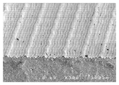
도 13b는 도 13a의 절삭 공구에 의해 절삭된 홈을 갖는 공작물의 사진.
여러 도면에서의 유사한 도면 부호는 유사한 요소를 나타낸다. 본 출원의 도면은 축척대로 도시되지는 않는다.<Figure 1>
1 is a conceptual perspective view of an apparatus suitable for a plunge or thread cutting machining process for producing microreplication tools.
<FIG. 2>
2 is a plan view of a cutting tool device that may be used in the plunge / thread cutting device of FIG.
3A to 3F
3A-3F are schematic plan cross-sectional views of a cutting tool for cutting grooves into a workpiece, and of the final grooves and protrusions formed in the workpiece.
4A to 4H
4A-4H are schematic plan cross-sectional views of a cutting tool for cutting grooves into a workpiece, and of the final grooves and protrusions formed in the workpiece.
5a to 4f
5A-4F are schematic plan cross-sectional views of a cutting tool for cutting grooves into a workpiece, and the final grooves and protrusions formed in the workpiece.
6A to 6C.
6A-6C are schematic plan cross-sectional views of a cutting tool for cutting grooves into a workpiece, and of the final grooves and protrusions formed in the workpiece;
7A and 7B
7A and 7B are top views of a cutting tool device that may be used in the plunge / thread cutting device of FIG.
8 to 10
8-10 are plan views of cutting tool devices that may be used in the plunge / thread cutting device of FIG.
11A to 11C.
11A-11C are schematic perspective views of a light directing film that may be produced using a workpiece machined using the plunge / thread cutting device of FIG. 1.
Figure 12a
12A is a schematic cross-sectional view of a cutting tool that may be used in the plunge / thread cutting device of FIG. 1.
12B and 12C.
12B and 12C are schematic cross-sectional views of a workpiece having grooves cut by the cutting tool of FIG. 12A.
Figure 13a
13A is a schematic cross-sectional view of a cutting tool that may be used in the plunge / thread cutting device of FIG. 1.
Figure 13b
FIG. 13B is a photograph of a workpiece having a groove cut by the cutting tool of FIG. 13A.
Like reference symbols in the various drawings indicate like elements. The drawings in this application are not drawn to scale.
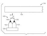
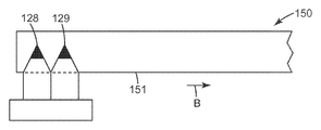
도 1은 장착 구조체(24)를 포함하는 절삭 공구 조립체(20)를 도시한다. 장착 구조체(24)는 절삭 팁(28)을 갖는 제1 절삭 공구 섕크(22)뿐만 아니라 절삭 팁(29)을 갖는 제2 절삭 공구 섕크(23)를 포함한다. 도 1에 도시된 절삭 공구 조립체는 2개의 절삭 팁을 포함하지만, 임의의 개수의 절삭 공구 섕크가 장착 구조체(24) 내에 장착될 수 있다. 절삭 팁(28, 29)은 공작물 내에 원하는 패턴의 미세구조체들을 생성하기 위해 동일한 형상 및 크기를 가질 수 있거나, 상이한 형상 및 크기일 수 있다. 본 명세서에 기술되는 공작물은 도 1에 도시된 공구(50)와 같은 미세복제 공구이지만, 본 발명의 방법은 플라이, 플런지 및 스레드 절삭 중 적어도 하나에 의해 기계 가공될 수 있는 임의의 공작물과 함께 사용될 수 있다. 도 1에서, 미세복제 공구(50)는 주조 롤이지만, 다른 미세복제 공구, 예를 들어 주조 벨트, 사출 금형, 압출 또는 엠보싱 공구, 또는 다른 공작물이 또한 절삭 공구 조립체(20)를 사용하여 생성될 수 있다.1 shows a
절삭 공구 조립체(20)는 절삭 공구 조립체(20)를 미세복제 공구(50)에 대해서 위치시키는 공구 가공 기계(tooling machine)(74) 내에 고정된다. 공구 가공 기계(74)는 절삭 공구 조립체(20)를 미세복제 공구(50)에 대해서 (화살표 A 및 B로 도시된 바와 같이) 횡방향으로 이동시킨다. 동시에, 미세복제 공구(50)는 화살표 C로 나타낸 방향으로 축을 중심으로 회전된다. 공구 가공 기계(74)는 미세복제 공구(50)의 표면(51) 내에 홈을 절삭하기 위해 플런지 절삭, 스레드 절삭, 플라이 절삭 기술 및/또는 이들의 조합(스레드 절삭 기술만이 본 명세서에 상세하게 설명될 것임)을 사용하여 절삭 공구 조립체(20)를 회전하는 미세복제 공구(50)와 접촉시킬 수 있다. 절삭 팁(28, 29)이 미세복제 공구(50)를 기계 가공함에 따라, 대응 패턴의 홈 및 돌출부가 미세복제 공구의 표면(51) 내에 형성된다. 또한, 고속 공구 서보(fast tool servo)(도 1에 도시되지 않음)가 선택적으로 절삭 공구 조립체(20)와 공구 가공 기계(74) 사이에 사용될 수 있다. 예를 들어, 고속 공구 서보는 절삭 공구 조립체(20)를 진동시킬 수 있으며, 이는 표면(51) 내에 특정의 미세구조체를 생성한다. 적합한 재료가 공구(50)에 대해 주조되거나 압출될 때, 절삭 팁(28, 29)에 의해 공구(50)의 표면(51) 내에 형성된 홈에 대응하는 돌출 구조체를 갖는 미세구조화된 물품이 형성된다.The cutting
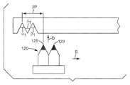
다수의 팁 절삭 공구(20)가 도 2에 더 상세하게 도시되어 있으며, 각각의 절삭 팁은 예를 들어 절삭 높이(H), 절삭 폭(W), 및 팁 각도(θ)를 포함하는 하나 이상의 변수에 의해 기술될 수 있다. 절삭 높이(H)는 절삭 팁이 공작물 내에 절삭할 수 있는 최대 깊이를 정의하며, 절삭 깊이로도 지칭될 수 있다. 물품이 공구에 대해 주조될 때, 절삭 깊이는 물품 내의 구조체의 (기부로부터 피크까지의) 높이에 대응한다. 절삭 폭(W)은 평균 절삭 폭, 또는 도 2에 나타낸 바와 같이 절삭 팁의 최대 절삭 폭으로서 정의될 수 있다. 물품이 공구에 대해 주조될 때, 절삭 폭은 물품 내의 구조체의 기부에서의 폭에 대응한다. 예를 들어, 높이(H) 및/또는 폭(W)은 대략 500 마이크로미터 미만, 대략 200 마이크로미터 미만, 대략 100 마이크로미터 미만, 대략 50 마이크로미터 미만, 대략 10 마이크로미터 미만, 대략 1.0 마이크로미터 미만, 또는 대략 0.1 마이크로미터 미만이 되도록 형성될 수 있다.A number of
절삭 팁(28, 29)의 크기를 정의하는 데 사용될 수 있는 다른 양은 종횡비(aspect ratio), 즉 높이(H) 대 폭(W)의 비이다. 종횡비는 대략 1:5 초과, 대략 1:2 초과, 대략 1:1 초과, 대략 2:1 초과, 또는 대략 5:1 초과가 되도록 한정될 수 있다.Another amount that can be used to define the size of the cutting
도 2의 변수(Y)는 절삭 공구(20) 내의 인접 절삭 팁(28 및 29)들 사이의 공칭 거리를 지칭하며, 본 명세서에서 피치 간격(P)의 정수(n)배로 정의된다. 본 명세서에서 용어 "피치"(P)는 공작물 내에 생성될 2개의 인접 특징부들, 예를 들어 도 1의 미세복제 공구(50)의 표면(51) 내에 각각의 절삭 팁(28, 29)에 의해 생성된 인접 홈(52, 53)들 사이의 거리를 지칭한다. 아래에 더 상세하게 설명되는 바와 같이, 본 명세서에서, n은 1 이상의 정수인 것으로 가정될 것인데, 이는 절삭 공구(20) 내의 절삭 팁(28, 29)이 1피치(P) 초과의 간격만큼 분리됨을 의미한다.Variable Y in FIG. 2 refers to the nominal distance between adjacent cutting
전형적으로, 절삭 팁(28, 29)들은 10 마이크로미터 미만, 또는 1 마이크로미터 미만, 또는 심지어 0.5 마이크로미터 정도의 허용 오차 내에서 장착 구조체(24) 내에 서로에 대해서 위치될 수 있다. 그러한 정밀 배치는 광학 필름, 접착 필름, 연마 필름, 기계식 체결구 등의 제조를 위한 미세복제 공구를 효과적으로 생성하기 위해 요구될 수 있다. 생성될 미세복제 공구의 치수에 따라, 공구 상의 인접 특징부들의 피치 간격 P는 대략 5000 마이크로미터 미만, 대략 1000 마이크로미터 미만, 대략 500 마이크로미터 미만, 대략 200 마이크로미터 미만, 대략 100 마이크로미터 미만, 대략 50 마이크로미터 미만, 대략 10 마이크로미터 미만, 대략 5 마이크로미터 미만, 대략 1 마이크로미터 미만일 수 있으며, 팁(28, 29)들의 0.5 마이크로미터 간격의 허용 오차에 근접할 수 있다.Typically, the cutting
일부 실시예에서, 절삭 팁(28, 29) 중 하나는 고정될 수 있고, 다른 절삭 팁은 절삭 팁(28, 29)이 원하는 간격을 가질 때까지 이동될 수 있다. 예를 들어, 도 2를 참조하면, 섕크(22)가 절삭 팁(28)을 정밀하게 위치시키기 위해 장착 구조체(24) 내에 고정될 수 있고, 이어서 절삭 팁(29)이 원하는 위치에 있을 때까지 섕크(23)가 장착 구조체(24) 내에서 이동될 수 있다. 섕크(22, 23)는 예를 들어 태핑(tapping), 쉬밍(shimming), 만곡(flexure), 또는 별개의 위치설정 단계에 의해 장착 구조체(24) 내에서 이동될 수 있다. 도 2에 도시되지 않은 대안적인 실시예에서, 절삭 팁(28, 29)은 단일 섕크 상에 제공될 수 있거나, 2개의 절삭 팁이 단일 결정으로 밀링될 수 있다.In some embodiments, one of the cutting
예를 들어, 집속 이온빔 밀링(focused ion beam milling) 공정에 의해 생성된 다이아몬드 팁은 전술된 다양한 높이, 폭, 피치 및 종횡비를 달성할 수 있다. 집속 이온빔 밀링은 다이아몬드의 원자들을 연마 제거(mill away)(때때로 어블레이션(ablation)으로 지칭됨)하기 위해 갈륨 이온과 같은 이온을 다이아몬드를 향해 가속시키는 공정을 말한다. 갈륨 이온의 가속은 다이아몬드로부터 원자들을 원자별로(atom by atom basis) 제거할 수 있다. 래핑(lapping) 또는 연삭(grinding)과 같은 저가의 기술이 또한 다이아몬드 팁 및/또는 도 2의 절삭 팁(28, 29)의 다른 부분을 형성하기 위해 단독으로 또는 이온빔 밀링과 조합하여 사용될 수 있다. 래핑은 유리된 연마재(loose abrasive)를 사용하여 다이아몬드로부터 재료를 제거하는 공정을 말하는 반면, 연삭은 매체(medium) 또는 기재(substrate)에 고정된 연마재를 사용하여 다이아몬드로부터 재료를 제거하는 공정을 말한다.For example, diamond tips produced by a focused ion beam milling process can achieve the various heights, widths, pitches, and aspect ratios described above. Focused ion beam milling refers to the process of accelerating ions, such as gallium ions, toward the diamond in order to mill away the diamond's atoms (sometimes referred to as ablation). Acceleration of gallium ions can remove atoms from the diamond on an atomic basis. Low cost techniques such as lapping or grinding may also be used alone or in combination with ion beam milling to form diamond tips and / or other portions of the cutting
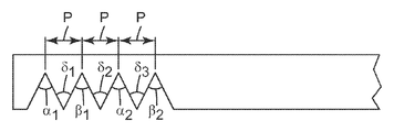
도 3a 및 도 3b를 참조하면, 절삭 공구(120)는 공구 섕크(122, 123) 및 절삭 팁(128, 129)을 갖는 공구 장착 구조체(124)를 포함한다. 절삭 공구(120)는 화살표 D의 방향을 따라 정위치로 이동될 수 있어서, 절삭 팁(128, 129)이 공작물(150)의 표면(151)과 결합하여 표면(151) 내에 선택된 깊이의 홈을 기계 가공한다. 공구(120) 내에서, 절삭 팁(128, 129)은 1피치 거리 P의 거리만큼 분리되는데, 즉 공식 Y = nP에서 n = 1이고 Y = P이며, 이는 절삭 공구(20) 내의 절삭 팁(28, 29)들 사이의 거리 Y가 공작물 내의 특징부들의 피치와 같을 것임을, 즉 Y = P임을 의미한다. 도 3c에 도시된 바와 같이, 공작물(150)의 제1 회전 동안에, 절삭 공구(120)는 방향 B를 따라 횡방향으로 이동되어, 제1 절삭 팁(128)이 제1 홈 α1을 절삭하고 제2 절삭 팁(129)이 인접한 제2 홈 β1을 절삭하게 한다. 홈 α1 및 β1의 골(trough)들은 거리 P만큼 분리되어 있다. 도 3d에서, 공작물(150)의 제2 회전 동안에, 공구(120)는 다시 방향 B를 따라 2P의 횡방향 거리만큼 이동되어, 제1 절삭 팁(128)이 표면(151) 내에 홈 α2를 절삭하고 제2 절삭 팁(129)이 홈 β2를 절삭하게 한다(도 3e). 역시, 홈 α2 및 β2의 골들은 거리 P만큼 분리되어 있다. 공작물(150)의 제3 회전 동안에, 공구(120)는 다시 방향 B를 따라 2P의 횡방향 거리만큼 이동되어, 제1 절삭 팁(128)이 표면(151) 내에 홈 α3를 절삭하고 제2 절삭 팁(129)이 홈 β3를 절삭하게 한다(도 3f). 역시, 홈 α3 및 β3의 골들은 거리 P만큼 분리되어 있다. 공작물(150)의 회전당 2P의 횡방향 증분의 절삭 공구(120)의 이동은 표면(151)의 원하는 부분(또는 실질적으로 전체)이 완전히 기계 가공될 때까지 계속된다.3A and 3B, the
상기의 내용에 비추어, 절삭 팁(128, 129)들 사이의 거리 Y가 nP와 같도록 선택되고 여기서 n은 홀수 정수이며, 공구가 공작물의 각각의 회전 동안에 2P의 거리만큼 전진되는 경우, 공작물(150)의 표면(151)을 완전히 처리하기 위해 1회의 절삭 패스만이 요구된다.In view of the above, if the distance Y between the cutting
도 3a 내지 도 3f에 설명된 방법은 1회 출발 또는 일 패스 공정으로 지칭되며, 이는 본 출원에서 절삭 공구가 공작물에 대해서 오직 하나의 횡방향으로 그의 출발 위치로부터 이동하여 단일 패스에서 공작물의 표면의 원하는 부분을 연속적으로 기계 가공함을 의미한다. 일부 실시예에서, 실질적으로 전체의 표면이 단일 패스에서 기계 가공되고, 다른 실시예에서 표면의 부분적인 기계 가공만이 요구된다.The method described in FIGS. 3A-3F is referred to as a one-start or one-pass process, in which the cutting tool is moved from its starting position in only one transverse direction with respect to the workpiece to This means that the desired part is machined continuously. In some embodiments, substantially the entire surface is machined in a single pass, and in other embodiments only partial machining of the surface is required.
본 출원에서, 다수회 출발(multi-start) 또는 다중 패스(multi-pass) 공정은 절삭 공구가 공작물의 제1 부분을 기계 가공하기 위해 제1 절삭 패스를 수행하고 공작물의 제2 부분을 기계 가공하기 위해 제2 절삭 패스를 수행하는 절삭 방법을 지칭한다.In the present application, a multi-start or multi-pass process involves a cutting tool performing a first cutting pass and machining a second portion of the workpiece to machine the first portion of the workpiece. It refers to a cutting method for performing a second cutting pass in order to.
제1 절삭 패스에서, 절삭 공구는 공작물의 표면의 제1 부분을 부분적으로 기계 가공하기 위해 공작물에 대해서 제1 횡방향을 따라 제1 출발 위치로부터 이동한다. 제1 절삭 패스의 결과, 공작물의 표면은 제1 패턴의 홈들을 포함한다. 제1 절삭 패스가 완료된 후에, 절삭 공구는 제1 횡방향과 반대인 제2 횡방향을 따라 제2 출발 위치로 이동된다. 이러한 "복귀" 패스 동안에, 절삭 공구는 공작물을 기계 가공하지 않는다. 제2 출발 위치는 제1 출발 위치와 동일하거나, 제1 출발 위치와 상이할 수 있다.In the first cutting pass, the cutting tool moves from the first starting position along the first transverse direction relative to the workpiece to partially machine the first portion of the surface of the workpiece. As a result of the first cutting pass, the surface of the workpiece includes the grooves of the first pattern. After the first cutting pass is completed, the cutting tool is moved to the second starting position along a second transverse direction opposite to the first transverse direction. During this "return" pass, the cutting tool does not machine the workpiece. The second starting position may be the same as the first starting position or different from the first starting position.
절삭 공구가 제2 출발 위치에 위치된 후에, 절삭 공구는 공작물의 제2 부분을 기계 가공하기 위해 제2 절삭 패스를 행한다. 공작물의 제2 부분은 제1 부분과 동일할 수 있거나, 제1 부분과 상이할 수 있다. 제2 출발 위치로부터, 절삭 공구는 공작물이 기계 가공될 때가지 제1 횡방향을 따라 이동된다.After the cutting tool is located in the second starting position, the cutting tool makes a second cutting pass to machine the second portion of the workpiece. The second portion of the workpiece may be the same as the first portion or may be different from the first portion. From the second starting position, the cutting tool is moved along the first transverse direction until the workpiece is machined.
예를 들어, 다수회 출발 공정에서, 일부 실시예에서 제2 출발 위치는 제1 출발 위치와 상이하고, 절삭 공구는 제1 절삭 패스에서 형성된 제1 패턴의 홈들과 상이한 제2 패턴의 홈들을 공작물 내에 형성한다.For example, in a multiple starting process, in some embodiments the second starting position is different from the first starting position, and the cutting tool is configured to workpiece the second pattern of grooves different from the grooves of the first pattern formed in the first cutting pass. To form.
다른 예에서, 다중 패스 공정에서, 일부 실시예에서 절삭 공구는 제1 위치와 동일한 제2 위치로 복귀한다. 이들 실시예에서, 절삭 공구는 제1 절삭 패스에서 형성된 제1 패턴의 홈들을 따른다. 그러나, 제2 절삭 패스에서, 절삭 공구는 공작물의 표면으로부터 추가의 재료를 제거하기 위해 공작물 내로 더 깊이 이동될 수 있다. 제2 절삭은 더 우수한 특징부 충실도를 제공할 수 있고(제1 절삭 패스에서 공작물의 표면으로부터 제거된 재료의 양이 너무 지나친 경우 일부 구조체에 대해 인열 또는 변형이 발생할 수 있음) 그리고/또는 제1 절삭 패스에서 형성된 홈에 추가의 구조적 특징부를 부가할 수 있다.In another example, in a multipass process, in some embodiments the cutting tool returns to the same second position as the first position. In these embodiments, the cutting tool follows the grooves of the first pattern formed in the first cutting pass. However, in the second cutting pass, the cutting tool can be moved deeper into the workpiece to remove additional material from the surface of the workpiece. The second cut may provide better feature fidelity (eg, tearing or deformation may occur for some structures if the amount of material removed from the surface of the workpiece in the first cutting pass is excessive) and / or the first Additional structural features may be added to the grooves formed in the cutting pass.
전형적으로, 1회 출발 공정은 다수회 출발 공정보다 더 정밀한 홈 및 피크 형성을 제공한다. 습도, 온도 등과 같은 절삭 조건은 다수의 절삭 패스 사이에서 변할 수 있으며, 이는 공작물 내에 기계 가공되는 홈의 정밀도에 악영향을 미칠 수 있다. 다수회 출발 절삭은 또한 절삭 공구가 공작물에 대해서 한 번 이상 재위치되는 것을 필요로 하며, 이는 단일 출발 방법보다 덜 정밀한 홈 배치를 야기할 수 있다. 단일 출발 절삭은 또한 다수회 출발 절삭보다 아주 더 빠르고 더 용이하며, 공구 가공 비용을 최소로 유지하는 데 바람직하다.Typically, a one start process provides more precise groove and peak formation than a multiple start process. Cutting conditions, such as humidity, temperature, etc., can vary between multiple cutting passes, which can adversely affect the precision of the grooves machined within the workpiece. Multiple starting cuts also require the cutting tool to be repositioned more than once with respect to the workpiece, which can result in less precise groove placement than the single starting method. Single start cutting is also much faster and easier than multiple start cutting and is desirable to keep tooling costs to a minimum.
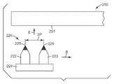
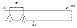
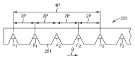
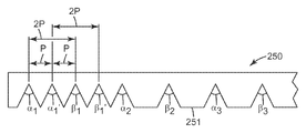
도 4a 및 도 4b를 참조하면, 절삭 공구(220)는 공구 섕크(222, 223) 및 절삭 팁(228, 229)을 갖는 공구 장착 구조체(224)를 포함한다. 절삭 공구(220)는 화살표 E의 방향을 이동되어, 절삭 팁(228, 229)이 공작물(250)의 표면(251) 내로 절삭하게 한다. 공구(220) 내에서, 절삭 팁(228, 229)은 2피치(P)의 거리만큼 분리되는데, 즉 공식 Y = nP에서 n = 2이고 Y =2P이다. 도 3b에 도시된 바와 같이, 공작물(250)의 제1 회전 동안에, 공구(220)는 출발점(252)에서 시작하여 방향 B를 따라 횡방향으로 이동하여, 제1 절삭 팁(228)이 공작물(250) 내에 제1 홈 α1을 절삭하고 제2 절삭 팁(229)이 인접한 제2 홈 β1을 절삭하게 한다. 홈 α1 및 β1의 골들은 거리 2P만큼 분리되어 있다. 공작물(250)의 제2 회전 동안에, 공구(220)는 표면(251) 내에 다음 세트의 홈들을 절삭하기 위해 방향 B를 따라 4P의 횡방향 거리만큼 이동되고, 제1 절삭 팁(228)은 홈 α2를 절삭하고 제2 절삭 팁(229)은 홈 β2를 절삭한다(도 4c). 역시, 홈 α2 및 β2의 골들은 거리 2P만큼 분리되어 있다. 공작물(250)의 제3 회전 동안에, 공구(220)는 다시 방향 B를 따라 4P의 횡방향 거리만큼 이동되고, 제1 절삭 팁(228)은 표면(251) 내에 홈 α3를 절삭하고 제2 절삭 팁(229)은 홈 β3를 절삭한다(도 4d). 홈 α3 및 β3의 골들은 거리 2P만큼 분리되어 있다. 공작물(250)의 회전당 방향 B를 따른 4P의 횡방향 증분의 절삭 공구(220)의 이동은 절삭 공구(220)가 표면(251)의 단부(도 4d에 도시되지 않음)에 도달할 때까지 계속된다.4A and 4B, the
도 4e를 참조하면, 이어서 공구(220)는 최초의 절삭 출발점(252)으로부터 1피치(P)의 거리만큼 오프셋된 제2 절삭 출발점(254)까지 방향 A를 따라 횡방향 후방으로 이동된다. 도 4f에 도시된 바와 같이, 제2 출발 뒤의 공작물(250)의 제1 회전 동안에, 공구(220)는 화살표 F의 방향을 따라 표면(251)을 향해 이동하고, 제1 절삭 팁(228)은 표면(251) 내에 제1 홈 α1' 및 제2 홈 β1'을 절삭하며, 각각의 홈의 골들은 거리 2P만큼 분리되어 있다. 또한, 홈 α1'의 골은 인접한 홈 α1의 골로부터 거리 P에 있다. 도 4g를 참조하면, 공작물(250)의 제2 회전 동안에, 공구(220)는 제2 절삭을 행하고 홈 α2' 및 β2'를 형성하기 위해 다시 거리 4P만큼 이동된다. 홈 α2' 및 β2'의 골들은 서로로부터 거리 2P에 있고, 홈 α2 및 β2로부터 각각 거리 P에 있다. 도 4h에 도시된 바와 같이, 공작물(250)의 제3 회전 동안에, 공구(220)는 제3 절삭을 행하고 홈 α3' 및 β3'를 형성하기 위해 다시 거리 4P만큼 이동된다. 홈 α3' 및 β3'의 골들은 서로로부터 거리 2P에 있고, 홈 α3 및 β3로부터 각각 거리 P에 있다. 이러한 절차는 표면(251)이 완전히 기계 가공될 때까지 계속된다.Referring to FIG. 4E, the
상기의 내용에 비추어, 절삭 팁(228, 229)들 사이의 거리 Y가 nP와 같도록 선택되고 여기서 n은 짝수 정수이며, 공구가 공작물의 각각의 회전 동안에 2nP의 거리만큼 전진되는 경우, 공작물(250)의 표면(251)을 완전히 처리하기 위해 2회의 절삭 출발이 사용될 수 있다.In view of the above, if the distance Y between the cutting
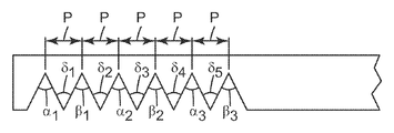
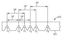
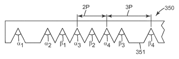
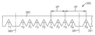
도 5a 및 도 5b를 참조하면, 절삭 공구(320)는 공구 섕크(322, 323) 및 절삭 팁(328, 329)을 갖는 공구 장착 구조체(324)를 포함한다. 절삭 공구(320)는 방향 B를 따라 횡방향으로 이동되고(도 1) 화살표 G의 방향으로 이동되어, 절삭 팁(328, 329)이 회전하는 공작물(350)의 표면(351) 내로 절삭하게 한다. 공구(320) 내에서, 절삭 팁(328, 329)들은 3피치(P)의 거리만큼 분리되는데, 즉 공식 Y = nP에서 n = 3이고 Y =3P이다. 도 5b에 도시된 바와 같이, 공작물(350)의 제1 회전 동안에, 제1 절삭 팁(328)은 제1 홈 α1을 절삭하고 제2 절삭 팁(329)은 제2 홈 β1을 절삭한다. 홈 α1 및 β1의 골들은 거리 3P만큼 분리되어 있다. 공작물(350)의 제2 회전 동안에, 공구(320)는 표면(351) 내에 다음 세트의 홈들을 절삭하기 위해 방향 B를 따라 2P의 횡방향 거리만큼 이동되고, 제1 절삭 팁(328)은 표면(351) 내에 홈 α2를 절삭하고 제2 절삭 팁(329)은 홈 β2를 절삭한다(도 5c). 역시, 홈 α2 및 β2의 골들은 거리 3P만큼 분리되어 있다. 공작물(350)의 제3 회전 동안에, 공구(320)는 방향 B를 따라 거리 2P의 횡방향 거리만큼 다시 이동되고, 제1 절삭 팁(328)은 표면(351) 내에 홈 α3를 절삭하고 제2 절삭 팁(329)은 홈 β3를 절삭한다(도 5d). 역시, 홈 α3 및 β3의 골들은 거리 3P만큼 분리되어 있다. 공작물(350)의 제4 회전 동안에, 도 5e에 도시된 바와 같이, 공구(350)는 방향 B로 2P의 횡방향 거리만큼 이동되고, 제1 절삭 팁(328)은 표면(351) 내에 홈 α4를 절삭하고 제2 절삭 팁(329)은 표면(351) 내에 홈 β4를 절삭한다. 역시, 홈 α4 및 β4의 골들은 거리 3P만큼 분리되어 있다. 공작물(350)의 회전당 방향 B를 따른 2P의 횡방향 증분의 절삭 공구(320)의 이동이 계속되어 3P의 거리만큼 분리된 홈 α5 및 β5를 형성하며, 표면(351)이 완전히 기계 가공될 때까지 절삭 공구(320)가 이동된다. 최종 절삭 후에, 공작물(350)은 최종 완성된 미세복제 공구를 형성하기 위해 선(360, 361)에서 트리밍(trimming)될 수 있다.5A and 5B, the cutting tool 320 includes a
단일 출발을 사용하여 인접 홈들 사이에 피치 P를 갖는 미세복제 공구를 제조하기 위해, 이중 절삭 팁을 갖고 절삭 팁 간격 Y = nP이고 여기서 n은 1보다 큰 홀수 정수인 절삭 공구가 선택될 수 있다. 절삭 공구는 회전하는 공작물의 각각의 회전 동안에 2P의 거리만큼 전진되어야 한다.To produce a microreplication tool having a pitch P between adjacent grooves using a single start, a cutting tool with a double cutting tip and cutting tip spacing Y = nP where n is an odd integer greater than 1 can be selected. The cutting tool must be advanced a distance of 2P during each rotation of the rotating workpiece.
상기 공작물은 예를 들어 광학 필름과 같은 미세복제된 물품을 제조하기 위한 미세복제 공구로서 사용될 수 있다. 광학 필름이 LCD와 같은 광학 장치에 인접하게 배치될 때 원하지 않는 광학 효과(예를 들어, 무아레(Moire) 패턴, 웨트아웃(wet-out) 등)를 생성하지 않는 것을 보장하기 위해, 광학 필름 내에 정밀한 구조체를 만드는 것이 바람직하다. 광학 필름 내에 정밀한 패턴의 구조체를 만들기 위해, 정밀한 홈 패턴을 갖는 미세복제 공구로 광학 필름을 제조하는 것이 중요하다. 홈들 사이의 피치(P)가 정밀하게 제어되는 고도로 정밀한 홈 패턴을 공작물 내에 만드는 것이 요구되는 경우, 미세복제 공구를 제조하는 데 사용되는 절삭 공구의 이중 절삭 팁들 사이의 거리 Y도 또한 정밀하게 제어되어야 한다. 예를 들어, 공작물 내의 원하는 패턴이 피치 간격 P만큼 분리된 인접 특징부들 및 P로부터의 최대 허용가능 이탈량 ±Δ를 포함한다고 가정한다. 이중 팁 절삭 공구가 패턴을 만드는 데 사용될 것이고, 따라서 제1 절삭 팁과 제2 절삭 팁 사이의 거리 Y = nP - 여기서, n은 ε/Δ보다 큰 정수이고 ε은 제1 절삭 팁과 제2 절삭 팁 사이의 원하는 간격을 달성할 때의 정밀도임 - 가 설정되어야 한다고 가정한다. 제1 절삭 팁과 제2 절삭 팁 사이의 실제 거리가 S인 경우, 피치 P의 홈들을 갖는 공작물을 제조하기 위해, 절삭 공구는 공작물의 각각의 회전에 대해서 2P'의 거리만큼 회전하는 공작물에 대해서 횡방향을 따라 전진되어야 하며, 여기서 P' = S/n이다.The workpiece can be used as a microreplication tool for producing microreplicated articles, for example optical films. To ensure that the optical film does not produce unwanted optical effects (e.g., moire patterns, wet-out, etc.) when placed adjacent to an optical device such as an LCD, It is desirable to make a precise structure. In order to make a precise patterned structure in the optical film, it is important to manufacture the optical film with a microreplication tool having a precise groove pattern. If it is desired to make in the workpiece a highly precise groove pattern in which the pitch P between the grooves is precisely controlled, the distance Y between the double cutting tips of the cutting tool used to manufacture the microreplica tool must also be precisely controlled. do. For example, suppose that the desired pattern in the workpiece includes the maximum allowable deviation amount ± Δ from P and adjacent features separated by a pitch interval P. FIG. A double tip cutting tool will be used to make the pattern, so the distance between the first and second cutting tips Y = nP-where n is an integer greater than ε / Δ and ε is the first cutting tip and the second cutting Assume that this is the precision when achieving the desired spacing between the tips. If the actual distance between the first and second cutting tips is S, in order to produce a workpiece with grooves of pitch P, the cutting tool is directed to a workpiece that is rotated by a distance of 2P 'for each rotation of the workpiece. Advance along the transverse direction, where P '= S / n.
예를 들어, 공작물 내의 원하는 피치(P)가 50 ㎛이고 이때 P의 최대 편차(Δ)가 ± 0.1 ㎛라고 가정한다. 절삭 공구의 이중 절삭 팁들 사이의 거리 Y = nP의 오차 ε가 10 ㎛라고 가정한다. 따라서, n은 ε/Δ 또는 10 ㎛/0.1 ㎛보다 크거나, 100보다 커야 한다. n = 111이 되도록 n이 선택되는 경우, 이중 절삭 팁들 사이의 실제 간격 S는 (111)(50 ㎛) = 5550 ㎛이다. S는 실제로 약 5560 ㎛이기 때문에, 실제 피치 P'는 5560 ㎛ /111 또는 50.09 ㎛가 되도록 선택되어야 한다. 5560 ㎛의 절삭 팁 간격의 상태에서, 절삭 공구는 공작물의 표면 상의 프리즘형 구조체들의 어레이에 동일한 높이, 동일한 기부 폭, 및 대칭적인 측벽을 제공하기 위해 공작물의 각각의 회전에 대해서 2P'의 횡방향 거리만큼 전진되어야 한다.For example, assume that the desired pitch P in the workpiece is 50 μm and the maximum deviation Δ of P is ± 0.1 μm. Assume that the error ε of the distance Y = nP between the double cutting tips of the cutting tool is 10 μm. Therefore, n must be greater than ε / Δ or 10 μm / 0.1 μm or greater than 100. When n is selected such that n = 111, the actual spacing S between the double cutting tips is (111) (50 μm) = 5550 μm. Since S is actually about 5560 μm, the actual pitch P ′ should be chosen to be 5560 μm / 111 or 50.09 μm. With a cutting tip spacing of 5560 μm, the cutting tool is 2P ′ transverse to each rotation of the workpiece to provide an array of prismatic structures on the surface of the workpiece with the same height, same base width, and symmetrical sidewalls. Advance by the distance.
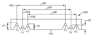
전술한 플라이, 플런지 및 스레드 절삭 방법은 미세복제되는 공구를 제조할 때 큰 유연성을 제공한다. 예를 들어, 광 지향 필름의 미세복제된 표면이 다른 필름의 표면과 접촉할 때 "웨트아웃"이 광학 디스플레이에 발생하여, 디스플레이 표면 영역에 걸쳐 광 강도의 편차를 야기할 수 있다. 웨트아웃 효과를 감소시키기 위해, 이중 팁 절삭 공구가 도 6a 내지 도 6c에 도시된 바와 같이 공작물(450)의 표면(451) 내에 홈을 절삭하는 데 사용될 수 있다. 공구(도시되지 않음)는 거리 8P만큼 이격된 2개의 절삭 팁을 갖고, 공작물(450)의 제1 회전 동안에, 제1 출발 위치(452)로부터, 깊이 d1을 각각 갖는 홈 α1 및 β1을 절삭한다. 공작물(450)의 제2 회전 동안에, 또한 깊이 d1을 각각 갖는 홈 α2 및 β2를 절삭하기 위해 공구는 거리 2(8P) = 16P만큼 횡방향으로 전진된다(도 6a에 도시되지 않음). 도 6b를 참조하면, 이러한 시퀀스를 표면(451)의 단부에 도달하기 위해 필요한 만큼 n회 반복한 후에, 공구는 제1 출발 위치(452)로부터 거리 P만큼 오프셋된 제2 출발 위치(454)로 복귀된다. 공작물(450)의 제1 후속 회전 동안에, 공구는 각각 8P만큼 이격되어 있고 d2 < d1의 깊이를 갖는 홈 α1' 및 β1'을 절삭한다. 공작물(450)의 제2 회전 동안에, 또한 깊이 d2 < d1를 각각 갖는 홈 α2' 및 β2'을 절삭하기 위해 공구는 거리 2(8P) = 16P만큼 횡방향으로 전진된다(도 6b에 도시되지 않음). 도 6c를 참조하면, 이러한 시퀀스를 표면(451)의 단부에 도달하기 위해 필요한 만큼 n회 반복한 후에, 공구는 제2 출발 위치(454)로부터 거리 P만큼 오프셋된 제3 출발 위치(456)로 복귀된다. 공작물(450)의 제1 후속 회전 동안에, 공구는 각각 8P만큼 이격되어 있고 d2 < d3 < d1의 깊이를 갖는 홈 α1'' 및 β1''을 절삭한다. 공작물(450)의 제2 회전 동안에, 또한 깊이 d2 < d3 < d1을 각각 갖는 홈 α2'' 및 β2''을 절삭하기 위해 공구는 거리 2(8P) = 16P만큼 횡방향으로 전진된다(도 6c에 도시되지 않음). 이어서 공구는 홈 α1''으로부터 거리 P만큼 오프셋된 제4 출발 위치로 복귀될 수 있으며, 표면(451)을 완전히 기계 가공하기 위해 필요한 만큼 공정이 n회 계속될 수 있다. 최종적인 공구는 다양한 깊이 d2 < d3 < d1의 홈들을 갖고, 이러한 다양한 깊이는 공구로부터 제조된 광학 필름이 광학 디스플레이에 사용될 때 웨트아웃 효과를 감소시키는 데 사용될 수 있다.The ply, plunge and thread cutting methods described above provide great flexibility in producing microreplicated tools. For example, “wet out” can occur in an optical display when the microreplicated surface of the light directing film contacts the surface of another film, causing variation in light intensity across the display surface area. To reduce the wet out effect, a dual tip cutting tool can be used to cut the grooves in the
도 7a에 도시된 다른 예에서, 절삭 공구(520)의 일부분은 공구 섕크(522, 523 및 525)를 갖는 공구 장착 구조체(524)를 포함한다. 각각의 공구 섕크(522, 523, 525)는 절삭 팁(528, 529 및 531)을 각각 포함한다. 절삭 팁(528, 529)은 각각 높이 h1을 가지며, 이는 절삭 팁(528, 529)이 공작물의 표면과 결합할 때 동일한 절삭 깊이 d1을 갖는 홈들을 생성할 것이다(도 7a에 도시되지 않음). 절삭 팁(528, 529)은 둥글게 되어 있으며, 이는 공작물 내의 깊이 d1의 모든 홈 내에 둥근 골을 기계 가공할 것이다. 절삭 공구(520) 내에서, 절삭 팁(528, 529)들은 2피치(P)의 거리만큼 분리되어 있는데, 즉 공식 Y = nP에서 n = 2이고 Y =2P이다. 따라서, 공작물 내의 깊이 d1의 둥근 골 홈들은 거리 2P만큼 분리될 것이다. 절삭 팁(531)은 h1보다 작은 높이 h2를 가지며, 이는 절삭 팁(531)이 공작물의 표면과 결합할 때 동일한 절삭 깊이 h2를 갖는 홈들을 생성할 것이다. 절삭 팁(531)은 뾰족하게 되어 있으며, 이는 공작물 내의 깊이 d2의 모든 홈 내에 V자 형상의 골을 기계 가공할 것이다. 절삭 공구(520) 내에서, 절삭 팁(531)은 2피치(P)의 거리만큼 분리되어 있는데, 즉 공식 Y = nP에서 n = 2이고 Y =2P이다. 따라서, 공작물 내의 깊이 d2의 V자 형상의 골 홈들도 또한 거리 2P만큼 분리될 것이다.In another example shown in FIG. 7A, a portion of cutting
사용시, 공구(520)는 공작물의 각각의 회전에 대해서 2(2P) = 4P의 거리만큼 전진될 것이고, 최종적인 홈 패턴은, 깊이 d2를 갖는 V자 형상의 홈에 의해 각각 분리되는, 거리 2P만큼 이격된 깊이 d1을 갖는 둥근 골 홈들을 포함할 것이다. V자 형상의 홈들도 또한 거리 2P만큼 분리될 것이다. 이러한 홈 패턴에 대응하는 리브(rib)들의 구조적 패턴을 포함하는 광학 필름은 스크래칭(scratching)에 대한 우수한 저항성을 갖는다.In use, the
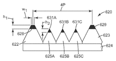
도 7b에 도시된 또 다른 예에서, 절삭 공구(620)의 일부분은 공구 섕크(622, 623 및 625A 내지 625C)를 갖는 공구 장착 구조체(624)를 포함한다. 각각의 공구 섕크(622, 623, 625)는 절삭 팁(628, 629 및 631A 내지 631C)을 각각 포함한다. 절삭 팁(628, 629)은 각각 높이 h1을 가지며, 이는 절삭 팁(628, 629)이 공작물의 표면과 결합할 때 동일한 절삭 깊이 d1을 갖는 홈들을 생성할 것이다(도 7b에 도시되지 않음). 절삭 팁(628, 629)은 거리 d3에 걸친 평평한 팁을 포함하며, 이는 공작물 내의 깊이 d1의 모든 홈의 바닥에 거리 d3의 폭의 평평한 골을 기계 가공할 것이다. 절삭 공구(620) 내에서, 절삭 팁(628, 629)은 4피치(P)의 거리만큼 분리되어 있는데, 즉 공식 Y = nP에서 n = 4이고 Y = 4P이다. 따라서, 공작물 내의 깊이 d1의 둥근 골 홈들은 거리 4P만큼 분리될 것이다. 절삭 팁(631A 내지 631C)은 h1보다 작은 높이 h2를 가지며, 이는 절삭 팁(631A 내지 631C)이 공작물의 표면과 결합할 때 동일한 절삭 깊이 h2를 갖는 홈들을 생성할 것이다. 절삭 팁(631A 내지 631C)은 뾰족하게 되어 있으며, 이는 공작물 내의 깊이 d2의 모든 홈 내에 V자 형상의 골을 기계 가공할 것이다. 절삭 공구(620) 내에서, 절삭 팁(631A 내지 631C)들은 1피치(P)의 거리만큼 분리되어 있는데, 즉 공식 Y = nP에서 n = 1이고 Y =P이다. 따라서, 공작물 내의 깊이 d2의 V자 형상의 골 홈들도 또한 거리 P만큼 분리될 것이다.In another example shown in FIG. 7B, a portion of the
사용시, 공구(620)는 공작물의 각각의 회전에 대해서 2(4P) = 8P의 거리만큼 전진될 것이고, 최종적인 홈 패턴은, 깊이 d2를 갖는 3개의 V자 형상의 홈에 의해 각각 분리되는, 거리 4P만큼 이격된 깊이 d1을 갖는 평평한 골 홈들을 포함할 것이다. V자 형상의 홈들은 거리 P만큼 분리될 것이다. 예를 들어, 제1 광학 필름이 도 7b에 도시된 공구를 사용하여 형성되는 경우, 절삭 팁(628, 629)에 의해 생성된 리브 상에 접착제가 적용될 수 있다. 이어서 동일하거나 유사한 홈 패턴을 갖는 제2 광학 필름이 제1 광학 필름 상에 적용될 수 있으며, 이때 제2 광학 필름 내의 홈들의 종축은 제1 광학 필름 내의 홈들의 종축에 직교하도록 위치된다. 이어서 최종적인 라미네이팅된 구조체가 광학 디스플레이 장치 내에 배치될 수 있다.In use, the
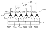
도 8에 도시된 또 다른 예에서, 절삭 공구(720)의 일부분은 공구 섕크(722A 및 722B, 723A 및 723B, 725A 및 725B)를 갖는 공구 장착 구조체(724)를 포함한다. 각각의 공구 섕크(722A 및 722B, 723A 및 723B, 725A 및 725B)는 절삭 팁(728A 및 728B, 729A 및 729B, 731A 및 731B)을 각각 포함한다. 모든 절삭 팁은 높이 h1을 가지며, 이는 절삭 팁들이 공작물의 표면과 결합할 때 동일한 절삭 깊이 d1을 갖는 홈들을 생성할 것이다(도 8에 도시되지 않음). 절삭 팁(728A 및 728B)은 끼인각 θ1을 갖고, 절삭 팁(731A 및 731B)은 끼인각 θ2를 가지며, 절삭 팁(729A 및 729B)은 끼인각 θ3를 갖고, θ1, θ2 및 θ3의 각각은 상이하다. 각각의 절삭 팁은 공작물 내에 대체로 V자 형상의 홈을 기계 가공할 것이지만, 각각의 홈은 약간 상이한 각도를 가질 것이다. 절삭 공구(720) 내에서, 절삭 팁(728A 및 728B, 729A 및 729B, 731A 및 731B)은 3피치(P)의 거리만큼 각각 분리되어 있는데, 즉 공식 Y = nP에서 n = 3이고 Y =3P이다.In another example shown in FIG. 8, a portion of cutting
사용시, 1회 출발 절삭을 제공하기 위해, 공구(720)는 공작물의 각각의 회전에 대해서 2P의 거리만큼 전진될 것이고, 최종적인 홈 패턴은, 각각 P만큼 이격되고 상이한 V자 끼인각을 갖는 3개의 홈들의 세트들을 포함할 것이다. 매 세 번째의 홈은 동일한 끼인각을 가질 것이다.In use, to provide one starting cut, the
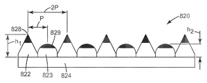
도 9에 도시된 다른 예에서, 절삭 공구(820)의 일부분은 공구 섕크(822 및 823)를 갖는 공구 장착 구조체(824)를 포함한다. 각각의 공구 섕크(822, 823)는 절삭 팁(828, 829)을 각각 포함한다. 절삭 팁(828)들은 각각 높이 h1을 가지며, 이는 절삭 팁(828)이 공작물의 표면과 결합할 때 동일한 절삭 깊이 d1을 갖는 홈들을 생성할 것이다(도 9에 도시되지 않음). 절삭 팁(828)은 V자 형상이며, 이는 공작물 내의 깊이 d1의 모든 홈 내에 V자 형상의 골을 기계 가공할 것이다. 절삭 공구(520) 내에서, 절삭 팁(528, 529)들은 2피치(P)의 거리만큼 분리되어 있는데, 즉 공식 Y = nP에서 n = 2이고 Y =2P이다. 따라서, 공작물 내의 깊이 d1의 V자 형상의 골 홈들은 거리 2P만큼 분리될 것이다. 절삭 팁(829)은 h1보다 작은 높이 h2를 가지며, 이는 절삭 팁(829)이 공작물의 표면과 결합할 때 동일한 절삭 깊이 h2를 갖는 홈들을 생성할 것이다. 절삭 팁(829)은 둥글게 되어 있으며, 이는 공작물 내의 깊이 d2의 모든 홈 내에 둥근 골을 기계 가공할 것이다. 절삭 공구(820) 내에서, 절삭 팁(829)들도 또한 2피치(P)의 거리만큼 분리되어 있는데, 즉 공식 Y = nP에서 n = 2이고 Y =2P이다. 따라서, 공작물 내의 깊이 d2의 둥근 골 홈들도 또한 거리 2P만큼 분리될 것이다.In another example shown in FIG. 9, a portion of cutting
사용시, 도 9의 공구(820)는 공작물의 각각의 회전에 대해서 2(2P) = 4P의 거리만큼 전진될 것이고, 최종적인 홈 패턴은, 깊이 d2를 갖는 둥근 골 홈에 의해 각각 분리되는, 거리 2P만큼 이격된 깊이 d1을 갖는 V자 형상의 골 홈들을 포함할 것이다. 둥근 골 홈들도 또한 거리 2P만큼 분리될 것이다.In use, the
도 10에 도시된 또 다른 예에서, 절삭 공구(920)의 일부분은 공구 섕크(922, 923 및 925A 내지 925C)를 갖는 공구 장착 구조체(924)를 포함한다. 각각의 공구 섕크(922, 923, 925)는 절삭 팁(928, 929 및 931A 내지 931C)을 각각 포함한다. 절삭 팁(928, 929)은 각각 높이 h1을 가지며, 이는 절삭 팁(928, 929)이 공작물의 표면과 결합할 때 동일한 절삭 깊이 d1을 갖는 홈들을 생성할 것이다(도 10에 도시되지 않음). 절삭 팁(928, 929)은 폭 d3를 갖는 평평한 팁을 포함하며, 이는 공작물 내의 깊이 d1의 모든 홈의 바닥에 거리 d3의 폭의 평평한 골을 기계 가공할 것이다. 절삭 공구(920) 내에서, 절삭 팁(928, 929)들은 4피치(P)의 거리만큼 분리되어 있는데, 즉 공식 Y = nP에서 n = 4이고 Y = 4P이다. 따라서, 공작물 내의 깊이 d1의 둥근 골 홈들은 거리 4P만큼 분리될 것이다. 절삭 팁(931A 내지 931C)은 h1보다 작은 높이 h2를 가지며, 이는 절삭 팁(931A 내지 931C)이 공작물의 표면과 결합할 때 동일한 절삭 깊이 h2를 갖는 홈들을 생성할 것이다. 절삭 팁(931A 내지 931C)은 둥글게 되어 있으며, 이는 공작물 내의 깊이 d2의 모든 홈 내에 둥근 골을 기계 가공할 것이다. 절삭 공구(920) 내에서, 절삭 팁(931A 내지 931C)들은 1피치(P)의 거리만큼 분리되어 있는데, 즉 공식 Y = nP에서 n = 1이고 Y = P이다. 따라서, 공작물 내의 깊이 d2의 둥근 골 홈들도 또한 거리 P만큼 분리될 것이다.In another example shown in FIG. 10, a portion of the
사용시, 공구(920)는 공작물의 각각의 회전에 대해서 2(4P) = 8P의 거리만큼 전진될 것이고, 최종적인 홈 패턴은 깊이 d2를 갖는 3개의 둥근 골 홈에 의해 각각 분리되는, 거리 4P만큼 이격된 깊이 d1을 갖는 평평한 골 홈들을 포함할 것이다. 둥근 골 홈들은 거리 P만큼 분리될 것이다. 이러한 홈 패턴에 대응하는 렌즈형(lenticular) 요소 및 리브의 구조적 패턴을 포함하는 광학 필름은 광학 디스플레이 장치 내의 인접 필름들에 대한 우수한 점착성을 갖는다.In use, the
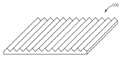
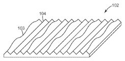
원하는 광학 효과를 갖는 광학 필름을 생성할 수 있는 특유의 패턴을 갖는 미세복제 공구를 제공하기 위해 다중 팁형(multi-tipped) 공구가 또한 스레드 및 플런지 절삭과 조합하여 사용될 수 있다. 예를 들어, 도 5a에 도시된 절삭 공구(320)가 홈 형성된 공작물을 기계 가공하기 위해 도 5b 내지 도 5f에 상세하게 설명된 바와 같은 스레드 절삭 절차에 사용된다고 가정한다. 일 실시예에서, 공작물은 롤 내의 홈 패턴에 대응하는 융기된 리브형 구조체들의 어레이를 갖는 광학 필름을 제조하는 데 사용될 수 있는 주조 롤일 수 있다. 리브들은 실질적으로 일정한 높이를 가지며, 그러한 광학 필름(100)의 예가 도 11a에 도시되어 있다.Multi-tipped tools can also be used in combination with thread and plunge cutting to provide microreplication tools with unique patterns that can produce optical films with the desired optical effect. For example, assume that the cutting tool 320 shown in FIG. 5A is used in a thread cutting procedure as described in detail in FIGS. 5B-5F to machine a grooved workpiece. In one embodiment, the workpiece can be a casting roll that can be used to make an optical film having an array of raised ribbed structures corresponding to a groove pattern in the roll. The ribs have a substantially constant height, an example of such an
그러나, 주조 롤이 도 5a의 공구(320)에 의해 기계 가공되지만, 공구(320)가 고속 공구 서보에 의해 진동된다고 가정한다. 일 실시예에서, 최종적인 광학 필름은 실질적으로 일정한 높이의 2개의 V자 형상의 홈에 의해 각각 분리되는, 3P만큼 이격된 파형의(변동하는 높이의) 홈들로 된 파형 쌍들을 포함하는, 도 11b의 필름(102)과 유사한 외양을 가질 것이다. 실질적으로 일정한 높이의 홈들의 각각은 P만큼 이격되어 있다.However, assume that the casting roll is machined by the tool 320 of FIG. 5A, but the tool 320 is vibrated by the high speed tool servo. In one embodiment, the final optical film includes waveform pairs of grooves of varying heights (of varying heights) separated by 3P, each separated by two V-shaped grooves of substantially constant height. It will have a similar appearance to film 102 of 11b. Each of the grooves of substantially constant height is spaced apart by P.
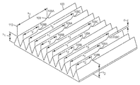
도 11c에 도시된 또 다른 실시예에서, 실질적으로 일정한 높이 h1의 제1 영역(107)을 각각 갖는 리브들의 어레이를 구비한 광학 필름(106)을 생성할 수 있는 주조 롤이 도 5a의 공구(320)에 의해 기계 가공된다고 또한 가정한다. 그러나, 선택된 간격(규칙적, 의사-규칙적, 또는 무작위적일 수 있음)으로, 공구(320)는 공작물 내로 거리 d만큼 추가로 밀어 넣어져 각각의 리브 상에 높이 h2 = h1 + d를 갖는 적어도 하나의 제2 영역(108)을 형성한다. 공구(320) 상의 절삭 팁들은 거리 3P만큼 이격되어 있기 때문에, 매 세 번째의 리브 상의 제2 영역(108)들은 직선 정렬(linear registration)될 것인데, 즉 예를 들어 필름의 에지와 같은 기준점으로부터 실질적으로 동일한 거리에 있을 것이다. 그러나, 세 번째 리브들의 각각의 쌍 사이의 2개의 리브는 세 번째 리브 쌍들 상의 리브들과 직선 정렬되지 않는 제2 영역을 가질 것이다(또는 세 번째 리브 쌍들 사이의 리브들은 심지어 제2 영역을 전혀 갖지 않을 수도 있음). 예를 들어, 도 11c에서, 제2 영역(108A)은 필름 에지의 기준점(110)으로부터 거리 x1에 있고, 제2 영역(108B)은 기준점(110)으로부터 거리 x2에 있고, 제2 영역(108C)은 기준점(110)으로부터 거리 x3에 있으며, 이때 x1 ≠ x2 ≠ x3이다. 제2 영역들의 그러한 배열은 웨트아웃을 감소시키거나 실질적으로 제거하는 동시에, 필름이 디스플레이 장치에 사용될 때 필름의 광학 이득을 실질적으로 유지한다.In another embodiment shown in FIG. 11C, a casting roll capable of producing an optical film 106 having an array of ribs each having a first region 107 of substantially constant height h1 is provided in the tool (FIG. 5A). It is also assumed to be machined by 320). However, at selected intervals (which may be regular, pseudo-regular, or random), the tool 320 is further pushed into the workpiece by the distance d so that at least one having a height h2 = h1 + d on each rib. The
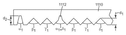
다수의 절삭 팁(1102, 1104, 1106 및 1108)을 포함하는 다른 절삭 공구(1100)가 도 12a에 도시되어 있다. 절삭 팁(1104, 1106, 1108)은 높이 h1을 갖는 한편, 절삭 팁(1102)은 높이 h2 > h1을 갖는다. 절삭 팁(1102)은 또한 폭 w를 갖는 평평한 절삭 영역을 포함하며, 절삭 공구의 전체 폭은 Y이다.Another
도 12b를 참조하면, 절삭 공구(1100)에 의한 제1 절삭 패스는 기재(1110) 내에 V자 형상의 단면 및 깊이 d1을 갖는 실질적으로 동일한 3개의 홈 β1, γ1, δ1을 생성하며, 이때 홈 β1은 절삭 팁(1104)에 의해 절삭되고, 홈 γ1은 절삭 팁(1106)에 의해 절삭되며, 홈 δ1은 절삭 팁(1108)에 의해 절삭된다. 절삭 공구(1100) 상의 절삭 팁(1102)은 폭 w의 평평한 "바닥(floor)" 및 깊이 d2 > d1를 갖는 대체로 V자 형상의 홈 α1을 생성한다.12B, the first cutting pass by the
도 12c를 참조하면, 제2 절삭 패스에서 절삭 공구(1100)는 공구(1100)의 전체 폭과 동일한 횡방향 거리 Y만큼 전진된다. 제2 절삭 패스에서, 절삭 팁(1102)은 기존의 홈 δ1 내로 절삭하여 깊이 d2를 갖는 평평한 바닥의 영역(1112)을 부가한다. 최종적인 홈은 원래의 홈 α1과 δ1 둘 모두의 특징을 포함하며, 제2 절삭 패스는 절삭 공구(1100) 상의 첫 번째 절삭 팁(1102) 및 마지막 절삭 팁(1108)의 부가 구조에 의해 복합 홈을 생성한다. 제2 절삭 패스에서, 절삭 팁(1104, 1106 및 1108)은 또한 깊이 d1을 각각 갖는 V자 형상의 홈 β2, γ2, δ2를 각각 생성한다. 후속 절삭 패스에서, 절삭 공구(1100)는 다시 횡방향 거리 Y만큼 전진될 것이며, 첫 번째의 홈 α1을 셈에 넣지 않고 매 세 번째의 홈 δn 내로 평평한 바닥의 구조가 부가될 것이다.12C, in the second cutting pass, the
도 13a는 상이한 형상, 폭 및 높이를 각각 갖는 6개의 절삭 팁(1202, 1204, 1206, 1208, 1210 및 1212)을 포함하는 절삭 공구(1200)의 단면도이다. 예를 들어, 절삭 공구(1204)는 높이 h1을 갖는 한편, 절삭 팁(1206)은 높이 h2 > h1을 갖는다. 절삭 팁(1212)은 높이 h3 < h1 < h3를 갖는다. 절삭 공구(1200) 내의 모든 절삭 팁들 중에서, 절삭 팁(1206)이 가장 큰 전체 폭 w를 갖는다. 절삭 공구(1200)의 전체 폭은 Y이다.13A is a cross-sectional view of a
도 13b는 공구(1200)가 본 명세서에 설명된 바와 같은 다수회 출발 절삭 공정에 사용되었을 때 생성된 패턴을 보여주는 포팅(potting) 재료의 현미경 사진이다. 제1 절삭 패스에서, 절삭 팁(1202, 1204, 1206, 1208, 1210 및 1212)은 각각의 홈(1302, 1304, 1306, 1308, 1310 및 1312)을 각각 생성한다. 제2 절삭 패스에서, 절삭 공구(1200)는 제2 배열의 홈들을 생성하기 위해 공구의 전체 폭과 동일한 거리 Y만큼 전진되고, 여기서 절삭 팁(1202)은 홈(1322)을 생성하고, 절삭 팁(1204)은 홈(1324)을 생성하며, 절삭 팁(1206)은 홈(1326)을 생성하며, 절삭 팁(1208)은 홈(1328)을 생성하고, 절삭 팁(1210)은 홈(1330)을 생성하며, 절삭 팁(1212)은 홈(1332)을 생성한다. 이러한 절삭 기술을 사용하여, 절삭 팁(1200)은 매 여섯 번째의 홈 내에 특유의 홈 형상을 형성한다.13B is a micrograph of the potting material showing the pattern generated when the
전술된 바와 같이, 본 발명은 디스플레이 시스템에 적용가능하며, 백라이트 디스플레이 및 후방 프로젝션 스크린과 같은, 다수의 광 관리 필름을 갖는 디스플레이 및 스크린 내의 외관 결함을 감소시키는 데 특히 유용한 것으로 여겨진다. 따라서, 본 발명은 전술한 특정 실시예로 제한되는 것으로 간주되어서는 안 되며, 오히려 첨부된 특허청구범위에 명확히 기재된 본 발명의 모든 태양을 포함하는 것으로 이해되어야 한다. 본 명세서의 개관시 본 발명이 적용될 수 있는 다양한 변형, 동등한 공정뿐만 아니라 다수의 구조가 본 발명과 관계된 분야의 당업자에게 쉽게 명확해질 것이다. 특허청구범위는 이러한 변형 및 장치를 포함하고자 한다.As mentioned above, the present invention is applicable to display systems and is believed to be particularly useful for reducing appearance defects in displays and screens with multiple light management films, such as backlit displays and rear projection screens. Accordingly, the present invention should not be considered limited to the specific embodiments described above, but rather should be understood to cover all aspects of the invention as clearly set forth in the appended claims. Various modifications, equivalent processes, as well as numerous structures to which the present invention may be applied, will be readily apparent to those skilled in the art related to the present invention in the overview of this specification. The claims are intended to cover such modifications and arrangements.
Claims (6)
공작물 내에 제1 특징부를 생성하는 제1 절삭 팁을 갖는 제1 공구 섕크(shank), 및 공작물 내에 제2 특징부를 생성하는 제2 절삭 팁을 갖는 제2 공구 섕크를 포함하는 절삭 공구 조립체를 제공하는 단계 - 여기서, 제1 절삭 팁과 제2 절삭 팁 사이의 거리 Y는 nP와 같고, n은 1보다 큰 홀수 정수임 - ;
절삭 공구 조립체에 대해서 공작물을 회전시키는 단계; 및
회전하는 공작물에 대해서 횡방향을 따라 절삭 공구를 전진시키는 단계 - 여기서, 절삭 공구는 공작물의 각각의 회전에 대해서 2P의 거리만큼 횡방향을 따라 전진됨 - 를 포함하는 방법.A method for cutting a pattern in a workpiece comprising adjacent features separated by a pitch spacing P,
Providing a cutting tool assembly comprising a first tool shank having a first cutting tip that creates a first feature in a workpiece, and a second tool shank having a second cutting tip that creates a second feature in the workpiece. Step, where the distance Y between the first and second cutting tips is equal to nP, and n is an odd integer greater than one;
Rotating the workpiece with respect to the cutting tool assembly; And
Advancing the cutting tool along the transverse direction with respect to the rotating workpiece, wherein the cutting tool is advanced along the transverse direction by a distance of 2 P for each rotation of the workpiece.
공작물 내에 제1 특징부를 생성하는 제1 절삭 팁을 갖는 제1 공구 섕크, 및 공작물 내에 제2 특징부를 생성하는 제2 절삭 팁을 갖는 제2 공구 섕크를 포함하는 절삭 공구 조립체를 제공하는 단계 - 여기서, 제1 절삭 팁과 제2 절삭 팁 사이의 거리 Y는 nP와 같고, n은 짝수 정수임 - ;
절삭 공구 조립체에 대해서 공작물을 회전시키는 단계;
출발 위치에서 시작하여, 회전하는 공작물에 대해서 횡방향을 따라 절삭 공구를 전진시키는 단계 - 여기서, 상기 공구는 공작물의 각각의 회전에 대해서 2Y의 거리만큼 횡방향을 따라 전진됨 - ;
절삭 공구를 출발 위치로 복귀시키고, 오프셋(offset) 출발 위치로 횡방향을 따라 거리 P만큼 절삭 공구를 전진시키는 단계; 및
오프셋 출발 위치에서 시작하여, 회전하는 공작물에 대해서 횡방향을 따라 절삭 공구를 전진시키는 단계 - 여기서, 절삭 공구는 공작물의 각각의 회전에 대해서 2Y의 거리만큼 전진됨 - 를 포함하는 방법.A method for cutting a pattern in a workpiece comprising adjacent features separated by a pitch spacing P, the method comprising:
Providing a cutting tool assembly comprising a first tool shank having a first cutting tip creating a first feature in a workpiece, and a second tool shank having a second cutting tip creating a second feature in the workpiece, wherein , The distance Y between the first and second cutting tips is equal to nP and n is an even integer;
Rotating the workpiece with respect to the cutting tool assembly;
Starting at the starting position, advancing the cutting tool along the transverse direction with respect to the rotating workpiece, wherein the tool is advanced along the transverse direction by a distance of 2Y for each rotation of the workpiece;
Returning the cutting tool to the starting position and advancing the cutting tool by a distance P along the transverse direction to an offset starting position; And
Starting at an offset starting position, advancing the cutting tool transversely relative to the rotating workpiece, wherein the cutting tool is advanced by a distance of 2Y for each rotation of the workpiece.
공작물 내에 제1 특징부를 생성하는 제1 절삭 팁을 갖는 제1 공구 섕크, 및 공작물 내에 제2 특징부를 생성하는 제2 절삭 팁을 갖는 제2 공구 섕크를 포함하는 절삭 공구 조립체를 제공하는 단계;
제1 절삭 팁과 제2 절삭 팁 사이의 거리 Y = nP를 설정하는 단계 - 여기서, n은 ε/Δ보다 큰 정수이고, ε은 제1 절삭 팁과 제2 절삭 팁 사이의 원하는 간격을 달성할 때의 정밀도임 - ;
제1 절삭 팁과 제2 절삭 팁 사이의 실제 거리 S를 측정하는 단계;
절삭 공구 조립체에 대해서 공작물을 회전시키는 단계; 및
회전하는 공작물에 대해서 횡방향을 따라 절삭 공구를 전진시키는 단계 - 여기서, 절삭 공구는 공작물의 각각의 회전에 대해서 2P'의 거리만큼 횡방향을 따라 전진되고, P' = S/n임 - 를 포함하는 방법.A method for cutting a pattern in a workpiece comprising adjacent features separated by a desired pitch spacing P and a maximum allowable deviation Δ from P, the method comprising:
Providing a cutting tool assembly comprising a first tool shank having a first cutting tip creating a first feature in a workpiece, and a second tool shank having a second cutting tip creating a second feature in the workpiece;
Setting the distance Y = nP between the first and second cutting tips, where n is an integer greater than ε / Δ, and ε is to achieve the desired spacing between the first and second cutting tips. Is the precision when-;
Measuring an actual distance S between the first and second cutting tips;
Rotating the workpiece with respect to the cutting tool assembly; And
Advancing the cutting tool along the transverse direction with respect to the rotating workpiece, wherein the cutting tool is advanced along the transverse direction by a distance of 2P 'for each rotation of the workpiece, with P' = S / n. How to.
제1 방향을 따라 연장되는 선형 미세구조체들의 열(row)들의 어레이를 포함하는 구조화된 주 표면(structured major surface)을 포함하고,
어레이 내의 각각의 선형 미세구조체는 일정한 높이를 갖는 복수의 제1 영역, 및 복수의 제1 영역의 일정한 높이보다 큰 최대 높이를 갖는 복수의 제2 영역을 포함하며,
n개의 열만큼 이격된 임의의 2개의 선형 미세구조체의 제2 영역들은 서로 직선 정렬(linear registration)되지만, 사이에 있는 선형 미세구조체들의 제2 영역들과는 직선 정렬되지 않으며, n은 2보다 큰 광 지향 필름.As a light directing film,
A structured major surface comprising an array of rows of linear microstructures extending along a first direction,
Each linear microstructure in the array includes a plurality of first regions having a constant height, and a plurality of second regions having a maximum height greater than a predetermined height of the plurality of first regions,
The second regions of any two linear microstructures spaced by n rows are linearly registered with each other, but not linearly aligned with the second regions of linear microstructures in between, and n is a light directing greater than two. film.
복수의 절삭 팁을 포함하는 절삭 공구 조립체를 제공하는 단계 - 여기서, 절삭 팁은 일정하지 않은 높이를 갖고, 절삭 팁들 사이의 거리 P는 일정하지 않으며, 절삭 공구 조립체는 폭 Y를 가짐 - ;
절삭 공구 조립체에 대해서 공작물을 회전시키는 단계; 및
회전하는 공작물에 대해서 횡방향을 따라 절삭 공구를 전진시키는 단계 - 여기서, 절삭 공구는 공작물의 각각의 회전에 대해서 Y의 거리만큼 횡방향을 따라 전진됨 - 를 포함하는 방법.As a method for cutting a pattern in a workpiece,
Providing a cutting tool assembly comprising a plurality of cutting tips, wherein the cutting tips have a non-uniform height, the distance P between the cutting tips is not constant, and the cutting tool assembly has a width Y;
Rotating the workpiece with respect to the cutting tool assembly; And
Advancing the cutting tool along the transverse direction relative to the rotating workpiece, wherein the cutting tool is advanced along the transverse direction by a distance of Y for each rotation of the workpiece.
Applications Claiming Priority (2)
| Application Number | Priority Date | Filing Date | Title |
|---|---|---|---|
| US17511809P | 2009-05-04 | 2009-05-04 | |
| US61/175,118 | 2009-05-04 |
Publications (1)
| Publication Number | Publication Date |
|---|---|
| KR20120016260A true KR20120016260A (en) | 2012-02-23 |
Family
ID=42314801
Family Applications (1)
| Application Number | Title | Priority Date | Filing Date |
|---|---|---|---|
| KR1020117028804A KR20120016260A (en) | 2009-05-04 | 2010-05-03 | Methods for making microreplication tools |
Country Status (7)
| Country | Link |
|---|---|
| US (1) | US20120058310A1 (en) |
| EP (1) | EP2427287A2 (en) |
| JP (1) | JP2012525990A (en) |
| KR (1) | KR20120016260A (en) |
| CN (1) | CN102458728A (en) |
| SG (1) | SG175840A1 (en) |
| WO (1) | WO2010129456A2 (en) |
Cited By (1)
| Publication number | Priority date | Publication date | Assignee | Title |
|---|---|---|---|---|
| KR20170050366A (en) * | 2015-10-30 | 2017-05-11 | 한국기계연구원 | Multi cutting module and multi cutting method using the same |
Families Citing this family (13)
| Publication number | Priority date | Publication date | Assignee | Title |
|---|---|---|---|---|
| JP5962058B2 (en) * | 2012-02-28 | 2016-08-03 | 富士ゼロックス株式会社 | Lens manufacturing equipment |
| JP5871701B2 (en) * | 2012-04-10 | 2016-03-01 | 株式会社神戸製鋼所 | Cutting tool manufacturing method |
| JP6382803B2 (en) * | 2012-06-27 | 2018-08-29 | スリーエム イノベイティブ プロパティズ カンパニー | Optical component array |
| JP5968728B2 (en) * | 2012-08-30 | 2016-08-10 | Ntn株式会社 | Turning method and turning apparatus |
| CN103302321B (en) * | 2013-05-29 | 2016-09-28 | 广州导新模具注塑有限公司 | Circular Fresnel processing patterns knife combination device, equipment and processing technique |
| DE102014117398B3 (en) * | 2014-11-27 | 2016-05-25 | Thielenhaus Technologies Gmbh | Method for generating grooves on a camshaft |
| JP7106774B2 (en) * | 2017-06-21 | 2022-07-26 | デクセリアルズ株式会社 | Microfabrication device, microfabrication unit, control device, master manufacturing method, and microfabrication method for master substrate |
| CN107790871A (en) * | 2017-12-08 | 2018-03-13 | 上海航天设备制造总厂有限公司 | The outer welder of aluminium-alloy pipe auger friction welding (FW) welding by both sides double-faced forming |
| JP7195110B2 (en) * | 2018-10-26 | 2022-12-23 | シチズン時計株式会社 | Machine tools and controllers |
| JP7214568B2 (en) * | 2019-05-29 | 2023-01-30 | シチズン時計株式会社 | Machine tools and controllers for these machine tools |
| CN110434403A (en) * | 2019-07-03 | 2019-11-12 | 福建夜光达科技股份有限公司 | High-efficiency and precision cuts the multitool mechanism and application method and application method of fine structure |
| CN117916037A (en) * | 2021-09-07 | 2024-04-19 | 诺维尔里斯公司 | System and method for producing textured casting molds for continuous belt casters |
| JP7132456B1 (en) | 2022-02-08 | 2022-09-06 | デクセリアルズ株式会社 | Microfabrication device, microfabrication unit, control device, master manufacturing method, and microfabrication method for master substrate |
Family Cites Families (9)
| Publication number | Priority date | Publication date | Assignee | Title |
|---|---|---|---|---|
| US1949515A (en) * | 1930-02-28 | 1934-03-06 | Norton Co | Method of turning and grinding round work surfaces |
| US2954570A (en) * | 1957-10-07 | 1960-10-04 | Couch Ace | Holder for plural thread chasing tools including tool clamping block with lubrication passageway |
| DE19817018B4 (en) * | 1998-04-17 | 2004-03-04 | Schmitt, Manfred Norbert, Dipl.-Kaufm. Dr. | Thread milling tool for larger thread lengths |
| US6095907A (en) * | 1998-10-02 | 2000-08-01 | Kennametal Inc. | Reciprocating assembly for abrading a workpiece |
| US7140812B2 (en) * | 2002-05-29 | 2006-11-28 | 3M Innovative Properties Company | Diamond tool with a multi-tipped diamond |
| US20040045419A1 (en) * | 2002-09-10 | 2004-03-11 | Bryan William J. | Multi-diamond cutting tool assembly for creating microreplication tools |
| US7445409B2 (en) * | 2005-10-19 | 2008-11-04 | 3M Innovative Properties Company | Cutting tool assembly including diamond cutting tips at half-pitch spacing for land feature creation |
| JP4837448B2 (en) * | 2006-06-14 | 2011-12-14 | 東芝機械株式会社 | Precision roll lathe |
| AU2008100847A4 (en) * | 2007-10-12 | 2008-10-09 | Bluescope Steel Limited | Method of forming textured casting rolls with diamond engraving |
-
2010
- 2010-05-03 EP EP10719568A patent/EP2427287A2/en not_active Withdrawn
- 2010-05-03 JP JP2012509866A patent/JP2012525990A/en not_active Withdrawn
- 2010-05-03 US US13/318,603 patent/US20120058310A1/en not_active Abandoned
- 2010-05-03 CN CN2010800262663A patent/CN102458728A/en active Pending
- 2010-05-03 KR KR1020117028804A patent/KR20120016260A/en not_active Application Discontinuation
- 2010-05-03 SG SG2011080082A patent/SG175840A1/en unknown
- 2010-05-03 WO PCT/US2010/033351 patent/WO2010129456A2/en active Application Filing
Cited By (1)
| Publication number | Priority date | Publication date | Assignee | Title |
|---|---|---|---|---|
| KR20170050366A (en) * | 2015-10-30 | 2017-05-11 | 한국기계연구원 | Multi cutting module and multi cutting method using the same |
Also Published As
| Publication number | Publication date |
|---|---|
| EP2427287A2 (en) | 2012-03-14 |
| US20120058310A1 (en) | 2012-03-08 |
| WO2010129456A3 (en) | 2011-01-06 |
| WO2010129456A2 (en) | 2010-11-11 |
| CN102458728A (en) | 2012-05-16 |
| JP2012525990A (en) | 2012-10-25 |
| SG175840A1 (en) | 2011-12-29 |
Similar Documents
| Publication | Publication Date | Title |
|---|---|---|
| KR20120016260A (en) | Methods for making microreplication tools | |
| KR100960754B1 (en) | Diamond tool with a multi-tipped diamond | |
| US7510462B2 (en) | Multi-diamond cutting tool assembly for creating microreplication tools | |
| KR101330857B1 (en) | Aligned multi-diamond cutting tool assembly for creating microreplication tools and method for creating the same | |
| JP2009512568A (en) | Cutting tool assembly containing half-pitch spaced diamond cutting tips to create land features | |
| RU2311293C2 (en) | Tooling equipment with the spiral turns for manufacture of the articles with the structured surface | |
| JP4221117B2 (en) | Molding sheet mold production equipment | |
| JPH06277952A (en) | Groove forming method by electric discharge machining | |
| US10414685B2 (en) | Substrate processing method | |
| RU2482939C1 (en) | Cutting indexable insert | |
| JP2014136304A (en) | Molding die, manufacturing method of the same, structure, and manufacturing method of the same | |
| JP6657076B2 (en) | A set of plates or parts obtained by cutting a block of metal or composite material | |
| RU2637709C1 (en) | Method of cutting node connections of cells of glass-fiber-reinforced honeycomb block | |
| JP4328583B2 (en) | Manufacturing method of workpiece by laser cutting device | |
| JP2011203661A (en) | Optical element, processed body and method for producing them | |
| JP2018034261A (en) | Gear shaving method |
Legal Events
| Date | Code | Title | Description |
|---|---|---|---|
| WITN | Application deemed withdrawn, e.g. because no request for examination was filed or no examination fee was paid |