KR20120008956A - Articulated bracket for fence - Google Patents
Articulated bracket for fence Download PDFInfo
- Publication number
- KR20120008956A KR20120008956A KR1020100070417A KR20100070417A KR20120008956A KR 20120008956 A KR20120008956 A KR 20120008956A KR 1020100070417 A KR1020100070417 A KR 1020100070417A KR 20100070417 A KR20100070417 A KR 20100070417A KR 20120008956 A KR20120008956 A KR 20120008956A
- Authority
- KR
- South Korea
- Prior art keywords
- fence
- bracket
- cross member
- joint
- fastening
- Prior art date
Links
Images


Classifications
-
- E—FIXED CONSTRUCTIONS
- E04—BUILDING
- E04H—BUILDINGS OR LIKE STRUCTURES FOR PARTICULAR PURPOSES; SWIMMING OR SPLASH BATHS OR POOLS; MASTS; FENCING; TENTS OR CANOPIES, IN GENERAL
- E04H17/00—Fencing, e.g. fences, enclosures, corrals
- E04H17/14—Fences constructed of rigid elements, e.g. with additional wire fillings or with posts
- E04H17/1413—Post-and-rail fences, e.g. without vertical cross-members
- E04H17/1447—Details of connections between rails and posts
- E04H17/1488—Brackets for connections between rails and posts
-
- E—FIXED CONSTRUCTIONS
- E04—BUILDING
- E04F—FINISHING WORK ON BUILDINGS, e.g. STAIRS, FLOORS
- E04F11/00—Stairways, ramps, or like structures; Balustrades; Handrails
- E04F11/18—Balustrades; Handrails
- E04F11/181—Balustrades
- E04F11/1817—Connections therefor
-
- E—FIXED CONSTRUCTIONS
- E04—BUILDING
- E04H—BUILDINGS OR LIKE STRUCTURES FOR PARTICULAR PURPOSES; SWIMMING OR SPLASH BATHS OR POOLS; MASTS; FENCING; TENTS OR CANOPIES, IN GENERAL
- E04H17/00—Fencing, e.g. fences, enclosures, corrals
- E04H17/14—Fences constructed of rigid elements, e.g. with additional wire fillings or with posts
- E04H17/1413—Post-and-rail fences, e.g. without vertical cross-members
- E04H17/1447—Details of connections between rails and posts
- E04H17/1448—Adjustable, angled or hinged connections
-
- E—FIXED CONSTRUCTIONS
- E04—BUILDING
- E04F—FINISHING WORK ON BUILDINGS, e.g. STAIRS, FLOORS
- E04F11/00—Stairways, ramps, or like structures; Balustrades; Handrails
- E04F11/18—Balustrades; Handrails
- E04F11/181—Balustrades
- E04F11/1817—Connections therefor
- E04F11/1834—Connections therefor with adjustable angle, e.g. pivotal connections
-
- E—FIXED CONSTRUCTIONS
- E04—BUILDING
- E04H—BUILDINGS OR LIKE STRUCTURES FOR PARTICULAR PURPOSES; SWIMMING OR SPLASH BATHS OR POOLS; MASTS; FENCING; TENTS OR CANOPIES, IN GENERAL
- E04H17/00—Fencing, e.g. fences, enclosures, corrals
- E04H17/14—Fences constructed of rigid elements, e.g. with additional wire fillings or with posts
- E04H17/1413—Post-and-rail fences, e.g. without vertical cross-members
- E04H17/1447—Details of connections between rails and posts
- E04H17/1452—Details of connections between rails and posts the ends of the rails are fixed on the lateral sides of the posts
-
- Y—GENERAL TAGGING OF NEW TECHNOLOGICAL DEVELOPMENTS; GENERAL TAGGING OF CROSS-SECTIONAL TECHNOLOGIES SPANNING OVER SEVERAL SECTIONS OF THE IPC; TECHNICAL SUBJECTS COVERED BY FORMER USPC CROSS-REFERENCE ART COLLECTIONS [XRACs] AND DIGESTS
- Y10—TECHNICAL SUBJECTS COVERED BY FORMER USPC
- Y10S—TECHNICAL SUBJECTS COVERED BY FORMER USPC CROSS-REFERENCE ART COLLECTIONS [XRACs] AND DIGESTS
- Y10S256/00—Fences
Abstract
Description
본 발명은 펜스의 가로재와 기둥재를 연결하기 위한 브라켓 구조에 관한 것으로서, 더욱 상세하게는 펜스의 가로재가 기둥재에 연결되어 상하좌우로 자유롭게 움직일 수 있도록 관절부를 구비한 펜스용 관절형 브라켓 구조에 관한 것이다.The present invention relates to a bracket structure for connecting a fence member and a pillar member, and more particularly, a joint bracket structure for a fence having a joint part to be freely moved up, down, left and right by connecting the fence member to the pillar member. It is about.
펜스는 경계를 삼기 위해 세워지는 구조물로, 보통 다리 난간 또는 등산로 등에 안전을 위해 세워지거나, 보호될 지역에 대한 외부인의 출입을 통제하기 위해 설치된다. 또한, 아파트, 빌딩 등의 계단에는 사용자의 추락을 방지하기 위해 설치되기도 하며, 장식을 위해 테라스 등의 건축물에 사용되기도 한다. 이러한 펜스는 지면에 세워지는 복수의 기둥재와, 상기 기둥재에 가로 방향으로 놓여 고정되는 가로재로 이루어진다. 이때 상기 기둥재와 가로재는 그 사이에 브라켓과 힌지를 구비하여 힌지축에 따라 가로재의 각도변경이 가능하도록 설치된다.A fence is a structure that is erected as a boundary, usually built for safety on bridge rails or hiking trails, or to control outsiders' access to protected areas. In addition, the stairs of apartments, buildings, etc. may be installed to prevent a user from falling, or may be used in buildings such as terraces for decoration. Such a fence is composed of a plurality of pillars erected on the ground, and a horizontal member placed in the horizontal direction and fixed to the pillars. At this time, the pillar and the cross member is provided so that the angle of the cross member according to the hinge axis having a bracket and a hinge therebetween.
종래의 한국등록특허 제941698호는 단일방향 회전이 가능한 힌지가 구비된 펜스를 개시한다. 상기 한국등록특허에 따르면, 지면에 세워지는 기둥재에는 한쌍의 거치판이 수직 형성되고, 각 거치판에는 서로 대향되게 관통홀이 형성되는 제1브라켓이 구비되며, 상기 관통홀에는 힌지핀이 끼움결합된다. 상기 힌지핀의 외주면에는 끼움관체가 구비되는데, 양 단부가 각 거치판의 마주보는 내측면에 접하는 탄성재질의 원통형 끼움관체가 상기 힌지핀의 외주면을 감싸면서 구비된다. 기둥재가 결합되는 제2브라켓에는 그 하부에 힌지공이 형성되어 있어서 힌지공이 상기 끼움관체에 선접되면서 회전이 가능하도록 구비된다. 상기 제2브라켓에는 가로재가 결합됨으로써, 상기 펜스가 구현된다.Conventional Korean Patent No. 961698 discloses a fence provided with a hinge capable of unidirectional rotation. According to the Korean registered patent, a pair of mounting plates are vertically formed on the pillars erected on the ground, and each mounting plate is provided with a first bracket having a through hole facing each other, and a hinge pin is fitted to the through holes. do. An outer circumferential surface of the hinge pin is provided with a fitting tube. An elastic cylindrical fitting tube having both ends in contact with the inner surface facing each mounting plate is provided while surrounding the outer circumferential surface of the hinge pin. In the second bracket to which the pillar material is coupled, a hinge hole is formed at a lower portion thereof so that the hinge hole is in contact with the fitting tube and is rotatable. The fence is implemented by coupling a cross member to the second bracket.
상기와 같은 종래 기술은 제1브라켓 및 제2브라켓에 의해 기둥재와 가로재의 연결부위가 외부로 크게 노출되어 미관상 좋지 못하고, 힌지에 의한 회전에 단일방향으로만 가능해서 펜스의 시공이 용이하지 못하며 설치 장소의 제약을 받게 된다.As described above, the first bracket and the second bracket are exposed to the outside by a large portion of the connection between the pillar and the cross member so that the appearance is not good, and the construction of the fence is not easy because it is possible to rotate by the hinge only in one direction. You will be constrained by the installation location.
본 발명은 상술한 바와 같은 문제점을 해결하기 위한 것으로, 기둥재와 가로재의 연결부위가 외부로 노출되는 부분을 줄이고, 가로재가 상하좌우로 자유롭게 회전이 가능하도록 펜스의 설치시 관절부가 구비된 브라켓 구조를 제공하는 것을 목적으로 삼고 있다.
The present invention is to solve the problems as described above, to reduce the portion exposed to the connection portion of the column member and the cross member to the outside, the bracket structure provided with the joint portion when installing the fence so that the cross member can be rotated freely up, down, left and right It is intended to provide.
상술한 바와 같은 목적을 달성하기 위해 본 발명은 지면에 세워지는 기둥재와 상기 기둥재 사이에 가로로 놓인 가로재를 결합시키는 펜스용 관절형 브라켓 구조에 있어서, 상기 기둥재에 결합되는 브라켓; 상기 브라켓의 상부면에 구비되고, 내측 중공부가 구비된 외부 관절부; 상기 외부 관절부 내측 중공부에 안치되어 상하좌우로 움직일 수 있는 내부 관절부; 및 일 단부가 상기 내부 관절부와 연결되며, 상기 가로재와 결합되는 가로재 체결부;를 구비한 펜스용 관절형 브라켓 구조를 제공한다.In order to achieve the object as described above, the present invention is an articulated bracket structure for a fence for coupling a horizontal member placed horizontally between the pillar and the pillar to stand on the ground, the bracket coupled to the pillar; An outer joint part provided on an upper surface of the bracket and provided with an inner hollow part; An inner joint part disposed in the inner hollow part of the outer joint part and movable up, down, left and right; And one end is connected to the inner joint portion, and provides a joint bracket structure for the fence having;
여기서, 상기 외부 관절부에는 상기 내측 중공부를 외부와 연통시키는 개구가 형성되는 것이 바람직하다.Here, the outer joint portion is preferably formed with an opening for communicating the inner hollow portion with the outside.
여기서, 상기 개구는 상기 내부 관절부가 상하 좌우로 움직임에 따라 상기 가로재 체결부가 상하좌우로 자유롭게 움직일 수 있도록 십(十)자 형태인 것이 바람직하다.Here, the opening is preferably in a cross shape so that the cross member fastening portion can move freely up, down, left and right as the inner joint moves up, down, left and right.
여기서, 가로재 체결부에는 슬롯이 형성되어 있어서, 상기 가로재는 상기 슬롯을 관통하는 체결부재에 의해 상기 가로재 체결부의 슬롯에 체결되는 것이 바람직하다.Here, the cross member fastening portion is formed with a slot, the cross member is preferably fastened to the slot of the cross member fastening portion by a fastening member penetrating the slot.
여기서, 상기 체결부재는 볼트와 너트로서, 볼트가 상기 슬롯 및 가로재를 통과하여 너트와 결합됨으로써 상기 가로재가 가로재 체결부에 체결되는 것이 바람직하다.Here, the fastening member is a bolt and a nut, it is preferable that the cross member is fastened to the cross member fastening portion by the bolt is coupled to the nut through the slot and the cross member.
여기서, 상기 브라켓과 외부 관절부는 일체로 성형된 것이 바람직하다.Here, it is preferable that the bracket and the external joint part are integrally molded.
여기서, 상기 내부 관절부와 가로재 체결부는 일체로 성형된 것이 바람직하다.
Here, the inner joint portion and the cross member fastening portion is preferably molded integrally.
본 발명에 따르면, 기둥재에 결합된 가로재가 상하좌우로 자유롭게 회전할 수 있고, 외부로 노출되는 연결부위가 적은 펜스를 구현할 수 있다.According to the present invention, the horizontal member coupled to the pillar member can freely rotate up, down, left, and right, and implement a fence having fewer connection parts exposed to the outside.
또한, 본 발명에 따르면, 외부 관절부 상에 상기 내부 관절부와 가로재 체결부의 연결부보다 크기가 큰 개구가 형성되어 상기 내부 관절부의 회전에 따라 상기 가로재 체결부 및 그에 연결된 가로재가 상하좌우로 자유롭게 회전할 수 있도록 한다.In addition, according to the present invention, an opening having a larger size than the connection portion of the inner joint portion and the cross member fastening portion is formed on the outer joint portion so that the cross member fastening portion and the cross member connected thereto are freely rotated up, down, left and right according to the rotation of the inner joint portion. Do it.
또한, 본 발명에 따르면, 상기 가로재 체결부 및 그에 연결된 가로재가 상하좌우로 자유롭게 회전할 수 있도록 하되, 외부 관절부에 십(十)자 형태의 개구를 구비하여 상기 개구의 형태를 따라 회전하도록 할 수 있다.In addition, according to the present invention, the horizontal member fastening portion and the horizontal member connected to the horizontal member to be freely rotated up, down, left and right, provided with an opening of the cross shape in the outer joint portion to rotate along the shape of the opening Can be.
또한, 본 발명에 따르면, 가로재 체결부에 슬롯이 형성되어 있어서 가로재가 슬롯을 통과하는 체결부재에 의해 가로재 체결부에 체결될 수 있도록 한다.In addition, according to the present invention, the cross member is formed in the fastening member so that the cross member can be fastened to the fastener by the fastening member passing through the slot.
또한, 본 발명에 따르면, 상기 체결부재로 볼트와 너트를 사용하여 상기 가로재를 가로재 체결부에 더욱 견고하게 결합시킬 수 있다.In addition, according to the present invention, by using the bolt and the nut as the fastening member it is possible to more firmly couple the cross member to the cross member fastening portion.
또한, 본 발명에 따르면, 브라켓과 외부 관절부는 일체로 성형되어 펜스의 시공효율성을 높이고, 브라켓과 외부 관절부의 결합에 필요한 자재를 생산하는데 필요한 비용을 절감할 수 있으며, 브라켓과 외부 관절부 간의 결합을 더욱 견고하게 할 수 있다.In addition, according to the present invention, the bracket and the external joint portion is integrally molded to increase the construction efficiency of the fence, reduce the cost required to produce the material required for the coupling of the bracket and the external joint portion, the coupling between the bracket and the external joint portion It can be more robust.
또한, 본 발명에 따르면, 상기 내부 관절부와 가로재 체결부는 일체로 성형되어 펜스의 시공효율성을 높이고, 내부 관절부와 가로재 체결부의 결합에 필요한 자재를 생산하는데 필요한 비용을 절감할 수 있으며, 내부 관절부와 가로재 체결부 간의 결합을 더욱 견고하게 할 수 있다.
In addition, according to the present invention, the inner joint portion and the cross member fastening portion is integrally formed to increase the construction efficiency of the fence, and can reduce the cost required to produce the material required for the coupling of the inner joint portion and the cross member fastening, the inner joint portion And the coupling between the fasteners can be more firm.
도 1은 종래의 브라켓 구조를 도시한 사시도이다.
도 2는 본 발명에 따른 외부 관절부가 구비된 브라켓을 도시한 사시도이다.
도 3은 본 발명에 따른 내부 관절부가 결합된 가로재 체결부를 도시한 사시도이다.
도 4는 도 2에 도시된 외부 관절부가 구비된 브라켓과 도 3에 도시된 내부 관절부가 결합된 가로재 체결부가 결합된 것을 도시한 사시도이다.
도 5는 도 4의 브라켓 구조가 절단된 상태를 도시한 사시도이다.
도 6은 도 3에 도시된 가로재 체결부에 볼트 및 너트를 이용하여 가로재를 결합시킨 것을 도시한 사시도이다.
도 7은 본 발명에 따른 브라켓 구조를 이용하여 기둥재와 가로재가 결합된 것을 도시한 부분 사시도이다.
도 8은 본 발명에 따른 펜스용 관절형 브라켓 구조가 구비된 펜스를 도시한 사시도이다.1 is a perspective view showing a conventional bracket structure.
2 is a perspective view showing a bracket provided with an external joint according to the present invention.
Figure 3 is a perspective view showing a fastener coupled to the inner joint portion according to the present invention.
FIG. 4 is a perspective view illustrating that a bracket having an external joint portion illustrated in FIG. 2 and a cross member fastening portion coupled to an internal joint portion illustrated in FIG. 3 are combined.
5 is a perspective view illustrating a state in which the bracket structure of FIG. 4 is cut.
FIG. 6 is a perspective view illustrating the coupling of the cross member by using a bolt and a nut to the cross member coupling unit illustrated in FIG. 3.
Figure 7 is a partial perspective view showing that the column member and the horizontal member is coupled using the bracket structure according to the present invention.
8 is a perspective view showing a fence provided with a joint bracket structure for the fence in accordance with the present invention.
이하, 본 발명에 따른 펜스용 관절형 브라켓 구조의 바람직한 실시예들을 도면을 참조하여 상세하게 설명한다. 이하에서 사용된 용어나 단어는 통상적이거나 사전적인 의미로 한정해서 해석되어서는 아니되며, 발명자는 그 자신의 발명을 최선의 방법으로 설명하기 위해 용어의 개념을 적절하게 정의할 수 있다는 원칙에 입각하여 본 발명의 기술적 사상에 부합하는 의미와 개념으로 해석되어야 할 것이다. Hereinafter, preferred embodiments of the articulating bracket structure for a fence according to the present invention will be described in detail with reference to the drawings. The terms or words used below should not be construed as being limited to ordinary or dictionary meanings, and the inventors can properly define the concept of terms in order to explain their invention in the best way. It should be interpreted as meanings and concepts corresponding to the technical spirit of the present invention.
본 발명에 따른 펜스용 관절형 브라켓 구조는 브라켓(10), 외부 관절부(20), 내부 관절부(30), 가로재 체결부(40)를 포함한다.Fence articulated bracket structure according to the present invention includes a
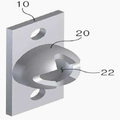
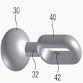
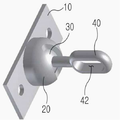
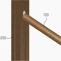
펜스를 구현하기 위해서는 지면에 세워지는 복수의 기둥재(200) 사이에 가로로 놓인 가로재(100)를 결합시켜야 하는데, 상기 기둥재(200)와 가로재(100)를 결합시키기 위해서 브라켓 구조가 사용된다. 상기 기둥재(200)는 브라켓(10)의 일면과 결합되고, 상기 기둥재(200)와 브라켓(10) 결합면의 반대쪽 면인 상기 브라켓(10)의 상부면에는 외부 관절부(20)가 구비된다. 상기 브라켓(10)과 외부 관절부(20)의 결합은 용접되거나 나사 결합 또는 리벳 결합으로 결합될 수 있고, 브라켓(10)과 외부 관절부(20)가 일체로 성형될 수도 있다. 도 2 및 도 4에 도시된 바와 같이, 상기 외부 관절부(20)에는 그 내측에 내측 중공부(22)가 구비되어 있어서 내부 관절부(30)가 상기 내측 중공부(22)에 안치된다. 상기 내부 관절부(30)는 내측 중공부(22) 내에서 자유롭게 회전이 가능하도록 구비되며, 그러기 위해서는 상기 내측 중공부(20)의 내주면과 상기 내부 관절부(30)의 외주면은 서로 대응되는 형태를 갖는 것이 바람직하고, 상하좌우로 자유롭게 회전 가능하기 위해서는 상기 내부 관절부(30)가 볼(ball) 형태인 것이 더욱 바람직하다. 상기 내부 관절부(30)는 가로재 체결부(40)의 일단부와 연결되는데, 도 3에 도시된 바와 같이, 내부 관절부(30)와 가로재 체결부(40)는 연결부(32)에 의해 연결될 수 있다. 상기 내부 관절부(30), 연결부(32) 및 가로재 체결부(40)는 용접되거나 나사 결합 또는 리벳 결합으로 연결될 수 있고, 일체로 성형되는 것도 가능하다. 상기 가로재 체결부(40)는 소정의 체결 방식을 통해 가로재(100)와 결합된다. 이로써, 상기 기둥재(200)와 가로재(100)가 결합된 펜스를 구현할 수 있으며, 상기 가로재 체결부(40)는 자유롭게 회전 가능한 내부 관절부(30)에 연결되어 있으므로, 결과적으로 가로재 체결부(40) 및 그에 결합되는 가로재가 상하좌우로 자유롭게 회전가능하게 된다. 또한, 가로재와 기둥재를 연결시키기 위한 브라켓 구조의 외부 노출을 최소화하여 미관상 좋은 펜스를 구현할 수 있다.In order to implement the fence, the
상기 외부 관절부(20)에는 내측 중공부(22)를 외부와 연통시키는 개구가 형성된다. 상기 외부 관절부(20)의 내측 중공부(22)에 안치되는 내부 관절부(30)는 가로재 체결부(40)와 연결부(32)를 통해서 연결되며, 상기 내부 관절부(30)에 연결된 연결부(32)가 외부로 노출될 수 있도록 상기 내측 중공부(22) 상에 개구가 형성된다. 상기 개구는 어떠한 형태라도 무방하다. 상기 내부 관절부(30)에 연결된 연결부(32)가 상기 개구를 통과하여 외부로 노출되며, 상기 연결부(32)의 노출된 일 단면에 상기 가로재 체결부(40)가 결합된다. 상기 내부 관절부(30)가 회전함에 따라 상기 연결부(32)도 함께 회전하므로, 그 회전 범위 이상의 크기를 가진 개구가 형성되어야 한다. 즉, 상기 개구는 연결부(32)의 단면보다 넓게 형성되어서 상기 내부 관절부(30)가 회전함에 따라 상기 연결부(32)의 회전에 필요한 반경을 확보하도록 한다.The
상기 개구는 십(十)자 형태일 수 있다. 상기 개구는 어떠한 형태라고 무방하지만, 십(十)자 형태를 갖는 경우에는 내부 관절부(30)가 상하좌우로 움직임에 따라 그에 연결된 가로재 체결부(40)도 상하좌우로 움직일 수 있을 뿐만 아니라, 시공시 상기 연결부(32) 및 가로재 체결부(40)가 원하는 방향으로만 움직이도록 가이드하는 역할을 할 수 있다.The opening may be in the shape of a cross. The opening may be any shape, but in the case of having a cross shape, as the inner
가로재 체결부(40)에는 슬롯(slot)(42)이 형성되어 있어서, 도 6에 도시된 바와 같이, 상기 슬롯(42) 상에 가로재(100)가 놓이고, 상기 슬롯(42) 및 가로재(100)를 관통하는 볼트 또는 리벳과 같은 체결부재에 의해 가로재가 상기 가로재 체결부(40)에 고정된다. 상기 볼트 또는 리벳과 같은 체결부재의 단면은 상기 슬롯(42)의 크기보다 작거나 동일하면 무방하나, 상기 체결부재의 단면이 상기 슬롯(42)의 크기와 동일하여 상기 체결부재가 슬롯(42)을 관통하여 가로재를 견고하게 고정시킬 수 있도록 하는 것이 바람직하다.
이때, 상기 체결부재가 볼트와 너트인 경우, 상기 볼트(50)가 슬롯(42) 및 가로재(100)를 통과한 후, 볼트 헤드의 반대쪽에서 볼트(50)와 너트(52)를 결합시켜서 가로재(100)를 가로재 체결부(40)에 견고하게 고정시킨다. 또한, 체결부재가 리벳인 경우에는, 리벳이 슬롯(42) 및 가로재(100)를 통과한 후, 상기 리벳이 슬롯(42) 및 가로재(100)로부터 이탈되지 않도록 해머 등으로 리벳 헤드를 두들겨서 고정시킨다. 슬롯(42)을 관통하여 가로재를 고정시키는 체결부재는 반드시 볼트나 리벳이 아니어도 무방하다.In this case, when the fastening member is a bolt and a nut, the
상기 브라켓(10)과 외부 관절부(20)는 일체로 사출 성형될 수 있다. 이로써 브라켓(10)과 외부 관절부(20)를 따로 결합시키는 공정을 필요로 하지 않아서 작업효율을 높이고 결합부재의 생산에 따른 비용을 감소시킬 수 있다.The
상기 내부 관절부(30)와 가로재 체결부(40)는 일체로 사출 성형될 수 있다. 이로써 내부 관절부(30)와 가로재 체결부(40)를 따로 결합시키는 공정을 필요로 하지 않아서 작업효율을 높이고 결합부재의 생산에 따른 비용을 감소시킬 수 있다.The inner
이상과 같이 본 발명은 비록 한정된 실시예와 도면에 의해 설명되었으나, 본 발명은 이것에 의해 한정되지 않으며 본 발명이 속하는 기술분야에서 통상의 지식을 가진 자에 의해 본 발명의 기술사상과 아래에 기재될 특허청구범위의 균등범위 내에서 다양하게 수정 및 변형될 수 있음은 물론이다.
As described above, although the present invention has been described by way of limited embodiments and drawings, the present invention is not limited thereto and is described below by the person skilled in the art and the technical spirit of the present invention. Of course, it can be variously modified and modified within the scope of equivalent claims.
10 : 브라켓
20 : 외부 관절부
22 : 내측 중공부
30 : 내부 관절부
32 : 내부 관절부와 가로재 체결부의 연결부
40 : 가로재 체결부
42 : 슬롯
50 : 볼트
52 : 너트
100 : 가로재
200 : 기둥재10: bracket
20: external joint
22: inner hollow part
30: internal joint
32: connecting portion of the inner joint and the cross member
40: cross member fastening portion
42: slot
50: Bolt
52: Nut
100: road ash
200: pillar material
Claims (7)
상기 기둥재에 결합되는 브라켓;
상기 브라켓의 일면에 구비되고, 내측 중공부가 구비된 외부 관절부;
상기 외부 관절부 내측 중공부에 안치되어 상하좌우로 움직일 수 있는 내부 관절부; 및
일 단부가 상기 내부 관절부와 연결되며, 상기 가로재와 결합되는 가로재 체결부;를 구비한 펜스용 관절형 브라켓 구조.
In the joint bracket structure for the fence for coupling the horizontal member placed horizontally between the pillar and the pillar standing on the ground,
A bracket coupled to the pillar material;
An outer joint part provided on one surface of the bracket and provided with an inner hollow part;
An inner joint part disposed in the inner hollow part of the outer joint part and movable up, down, left and right; And
A joint bracket structure for a fence having an end portion connected to the inner joint portion and coupled with a horizontal member coupled to the horizontal member.
상기 외부 관절부에는 상기 내측 중공부를 외부와 연통시키는 개구가 형성되는 것을 특징으로 하는 펜스용 관절형 브라켓 구조.
The method of claim 1,
The outer joint portion is an articulated bracket structure for a fence, characterized in that the opening is formed to communicate the inner hollow portion with the outside.
상기 개구는 상기 내부 관절부가 상하 좌우로 움직임에 따라 상기 가로재 체결부가 상하좌우로 자유롭게 움직일 수 있도록 십(十)자 형태인 것을 특징으로 하는 펜스용 관절형 브라켓 구조.
The method of claim 2,
The opening has an articulated bracket structure for a fence, characterized in that the cross-shaped fastening portion to move freely up, down, left and right as the inner joint moves up, down, left and right.
상기 가로재 체결부에는 슬롯이 형성되어 있어서, 상기 가로재는 상기 슬롯 및 가로재를 관통하는 체결부재에 의해 상기 가로재 체결부의 슬롯에 체결되는 것을 특징으로 하는 펜스용 관절형 브라켓 구조.
The method of claim 1,
The cross member fastening portion is formed with a slot, the cross member is a joint bracket structure for the fence characterized in that the fastening member is fastened to the slot member of the cross member by a fastening member penetrating the slot member.
상기 체결부재는 볼트와 너트로서, 볼트가 상기 슬롯 및 가로재를 통과하여 너트와 결합됨으로써 상기 가로재가 가로재 체결부에 체결되는 것을 특징으로 하는 펜스용 관절형 브라켓 구조.
The method of claim 4, wherein
The fastening member is a bolt and a nut, the joint member structure for the fence, characterized in that the bolt is coupled to the nut through the slot and the cross member is fastened to the cross member fastening portion.
상기 브라켓과 외부 관절부는 일체로 성형된 것을 특징으로 하는 펜스용 관절형 브라켓 구조.
The method of claim 1,
The bracket and the outer joint portion is a joint bracket structure for the fence, characterized in that molded integrally.
상기 내부 관절부와 가로재 체결부는 일체로 성형된 것을 특징으로 하는 펜스용 관절형 브라켓 구조.
The method of claim 1,
The joint bracket structure for the fence, characterized in that the inner joint portion and the cross member fastening portion formed integrally.
Priority Applications (5)
| Application Number | Priority Date | Filing Date | Title |
|---|---|---|---|
| KR1020100070417A KR20120008956A (en) | 2010-07-21 | 2010-07-21 | Articulated bracket for fence |
| JP2013519575A JP5660212B2 (en) | 2010-07-21 | 2011-07-08 | Articulated bracket for fence |
| CN201180035165.7A CN103003511B (en) | 2010-07-21 | 2011-07-08 | For the articulated stand of guardrail |
| US13/810,376 US20130119335A1 (en) | 2010-07-21 | 2011-07-08 | Articulated bracket for fence |
| PCT/KR2011/005029 WO2012011691A2 (en) | 2010-07-21 | 2011-07-08 | Articulated bracket for fence |
Applications Claiming Priority (1)
| Application Number | Priority Date | Filing Date | Title |
|---|---|---|---|
| KR1020100070417A KR20120008956A (en) | 2010-07-21 | 2010-07-21 | Articulated bracket for fence |
Publications (1)
| Publication Number | Publication Date |
|---|---|
| KR20120008956A true KR20120008956A (en) | 2012-02-01 |
Family
ID=45497264
Family Applications (1)
| Application Number | Title | Priority Date | Filing Date |
|---|---|---|---|
| KR1020100070417A KR20120008956A (en) | 2010-07-21 | 2010-07-21 | Articulated bracket for fence |
Country Status (5)
| Country | Link |
|---|---|
| US (1) | US20130119335A1 (en) |
| JP (1) | JP5660212B2 (en) |
| KR (1) | KR20120008956A (en) |
| CN (1) | CN103003511B (en) |
| WO (1) | WO2012011691A2 (en) |
Cited By (1)
| Publication number | Priority date | Publication date | Assignee | Title |
|---|---|---|---|---|
| KR101250988B1 (en) * | 2012-05-31 | 2013-04-05 | 임정례 | Bracket of fence |
Families Citing this family (3)
| Publication number | Priority date | Publication date | Assignee | Title |
|---|---|---|---|---|
| FR2997433B1 (en) * | 2012-10-26 | 2015-08-21 | Lippi La Cloture | ASSEMBLED FENCING PANEL WITHOUT WELDING AND FENCE HAVING SUCH A PANEL |
| USD775940S1 (en) * | 2014-04-10 | 2017-01-10 | James Klatka | PVC swivel connector |
| IT201900024850A1 (en) * | 2019-12-19 | 2021-06-19 | Faraone S R L | FIXING SYSTEM TO CONNECT ONE OR MORE PANELS TO AN INSTALLATION STRUCTURE TO DEFINE TECHNICAL PROTECTION AND / OR DELIMITATION AND / OR FURNITURE STRUCTURES. |
Family Cites Families (10)
| Publication number | Priority date | Publication date | Assignee | Title |
|---|---|---|---|---|
| US590835A (en) * | 1897-09-28 | Slip-joint for scrub-brushes | ||
| US1664893A (en) * | 1926-02-20 | 1928-04-03 | Meyering Bernard | Joint |
| US4060222A (en) * | 1976-06-22 | 1977-11-29 | Sheldon Pitkin | Prefabricated fencing system |
| KR890000735Y1 (en) * | 1985-06-19 | 1989-03-25 | 손창현 | Connecting device for wire fence |
| KR100431952B1 (en) * | 2002-04-12 | 2004-05-17 | (주)뉴그린 밸리 | A Fence |
| JP3126080U (en) * | 2006-07-31 | 2006-10-12 | 株式会社ザイエンス | Crosspiece fixing bracket |
| KR100802500B1 (en) * | 2007-01-17 | 2008-02-14 | 주식회사강산 | Crossrail angle adjustment apparatus for barrier constructed on inclined ground |
| US7640617B2 (en) * | 2007-03-09 | 2010-01-05 | Helen Of Troy Limited | Cleaning device including a pivot joint |
| CN201011189Y (en) * | 2007-03-14 | 2008-01-23 | 严敏飞 | Tiltable railing |
| KR100993547B1 (en) * | 2008-06-20 | 2010-11-10 | (주)중동 | Fence junction coupling device |
-
2010
- 2010-07-21 KR KR1020100070417A patent/KR20120008956A/en not_active Application Discontinuation
-
2011
- 2011-07-08 WO PCT/KR2011/005029 patent/WO2012011691A2/en active Application Filing
- 2011-07-08 US US13/810,376 patent/US20130119335A1/en not_active Abandoned
- 2011-07-08 CN CN201180035165.7A patent/CN103003511B/en not_active Expired - Fee Related
- 2011-07-08 JP JP2013519575A patent/JP5660212B2/en not_active Expired - Fee Related
Cited By (1)
| Publication number | Priority date | Publication date | Assignee | Title |
|---|---|---|---|---|
| KR101250988B1 (en) * | 2012-05-31 | 2013-04-05 | 임정례 | Bracket of fence |
Also Published As
| Publication number | Publication date |
|---|---|
| JP2013531156A (en) | 2013-08-01 |
| US20130119335A1 (en) | 2013-05-16 |
| CN103003511B (en) | 2015-09-23 |
| WO2012011691A2 (en) | 2012-01-26 |
| WO2012011691A3 (en) | 2012-04-19 |
| CN103003511A (en) | 2013-03-27 |
| JP5660212B2 (en) | 2015-01-28 |
Similar Documents
| Publication | Publication Date | Title |
|---|---|---|
| CA2413295C (en) | Railing with pivotally connected pickets | |
| KR200464339Y1 (en) | joint structure guardrail of angle and stretch controller | |
| JP6045180B2 (en) | System handrail and horizontal handrail unit, flip-up handrail unit and auxiliary handrail unit used therefor | |
| KR101177528B1 (en) | Articulated shock-absorbing fence | |
| JP4856744B2 (en) | Linkage mechanism for linear members of boundary structures | |
| US8671963B2 (en) | Overhead combined tent structure | |
| KR101302070B1 (en) | Angle and direction adjusting joint of design fence between parapet and rail | |
| KR20120008956A (en) | Articulated bracket for fence | |
| JP2013092034A5 (en) | ||
| KR102252869B1 (en) | Wooden fence with improved ease of fixing the lower part of the wooden post and prevention of vibration and noise | |
| KR102156673B1 (en) | Hybrid bracket for wood fence | |
| KR100867322B1 (en) | Post of prefabricated structure and handrail coupling structure | |
| KR102023036B1 (en) | A post for wood fence | |
| RU2659102C1 (en) | Spherical detachable residential module | |
| KR20120033608A (en) | Angle control type railing apparatus | |
| KR101631566B1 (en) | Crossbar coupling device of handrail and the installation method | |
| KR101725252B1 (en) | Smart pannel bracket device for artificial rock wall | |
| KR200482903Y1 (en) | Lifeline mounting pole | |
| KR102451668B1 (en) | Handrail structure | |
| KR100455561B1 (en) | Constructing stone exterior wall fixture | |
| KR101032763B1 (en) | A fence connector a easy control appartuss for angle | |
| KR101994679B1 (en) | Connector for handrail | |
| KR20200077223A (en) | construction assembly of fence with easy to construct at slope | |
| KR101787246B1 (en) | Assembly of outside panels on the wall | |
| KR102423773B1 (en) | Railing connection device using housing |
Legal Events
| Date | Code | Title | Description |
|---|---|---|---|
| A201 | Request for examination | ||
| E601 | Decision to refuse application |