KR20120006992A - Electrical energy storage cell and cell block, electrical energy storage device and the vehicle comprising the same - Google Patents
Electrical energy storage cell and cell block, electrical energy storage device and the vehicle comprising the same Download PDFInfo
- Publication number
- KR20120006992A KR20120006992A KR1020117023177A KR20117023177A KR20120006992A KR 20120006992 A KR20120006992 A KR 20120006992A KR 1020117023177 A KR1020117023177 A KR 1020117023177A KR 20117023177 A KR20117023177 A KR 20117023177A KR 20120006992 A KR20120006992 A KR 20120006992A
- Authority
- KR
- South Korea
- Prior art keywords
- electrical energy
- cell
- energy storage
- current collector
- seam
- Prior art date
Links
Images


Classifications
-
- H—ELECTRICITY
- H01—ELECTRIC ELEMENTS
- H01M—PROCESSES OR MEANS, e.g. BATTERIES, FOR THE DIRECT CONVERSION OF CHEMICAL ENERGY INTO ELECTRICAL ENERGY
- H01M50/00—Constructional details or processes of manufacture of the non-active parts of electrochemical cells other than fuel cells, e.g. hybrid cells
- H01M50/20—Mountings; Secondary casings or frames; Racks, modules or packs; Suspension devices; Shock absorbers; Transport or carrying devices; Holders
-
- H—ELECTRICITY
- H01—ELECTRIC ELEMENTS
- H01M—PROCESSES OR MEANS, e.g. BATTERIES, FOR THE DIRECT CONVERSION OF CHEMICAL ENERGY INTO ELECTRICAL ENERGY
- H01M10/00—Secondary cells; Manufacture thereof
- H01M10/05—Accumulators with non-aqueous electrolyte
- H01M10/052—Li-accumulators
-
- H—ELECTRICITY
- H01—ELECTRIC ELEMENTS
- H01M—PROCESSES OR MEANS, e.g. BATTERIES, FOR THE DIRECT CONVERSION OF CHEMICAL ENERGY INTO ELECTRICAL ENERGY
- H01M50/00—Constructional details or processes of manufacture of the non-active parts of electrochemical cells other than fuel cells, e.g. hybrid cells
- H01M50/10—Primary casings, jackets or wrappings of a single cell or a single battery
- H01M50/102—Primary casings, jackets or wrappings of a single cell or a single battery characterised by their shape or physical structure
- H01M50/103—Primary casings, jackets or wrappings of a single cell or a single battery characterised by their shape or physical structure prismatic or rectangular
-
- H—ELECTRICITY
- H01—ELECTRIC ELEMENTS
- H01M—PROCESSES OR MEANS, e.g. BATTERIES, FOR THE DIRECT CONVERSION OF CHEMICAL ENERGY INTO ELECTRICAL ENERGY
- H01M50/00—Constructional details or processes of manufacture of the non-active parts of electrochemical cells other than fuel cells, e.g. hybrid cells
- H01M50/10—Primary casings, jackets or wrappings of a single cell or a single battery
- H01M50/131—Primary casings, jackets or wrappings of a single cell or a single battery characterised by physical properties, e.g. gas-permeability or size
-
- H—ELECTRICITY
- H01—ELECTRIC ELEMENTS
- H01M—PROCESSES OR MEANS, e.g. BATTERIES, FOR THE DIRECT CONVERSION OF CHEMICAL ENERGY INTO ELECTRICAL ENERGY
- H01M50/00—Constructional details or processes of manufacture of the non-active parts of electrochemical cells other than fuel cells, e.g. hybrid cells
- H01M50/10—Primary casings, jackets or wrappings of a single cell or a single battery
- H01M50/147—Lids or covers
-
- H—ELECTRICITY
- H01—ELECTRIC ELEMENTS
- H01M—PROCESSES OR MEANS, e.g. BATTERIES, FOR THE DIRECT CONVERSION OF CHEMICAL ENERGY INTO ELECTRICAL ENERGY
- H01M50/00—Constructional details or processes of manufacture of the non-active parts of electrochemical cells other than fuel cells, e.g. hybrid cells
- H01M50/10—Primary casings, jackets or wrappings of a single cell or a single battery
- H01M50/172—Arrangements of electric connectors penetrating the casing
- H01M50/174—Arrangements of electric connectors penetrating the casing adapted for the shape of the cells
- H01M50/176—Arrangements of electric connectors penetrating the casing adapted for the shape of the cells for prismatic or rectangular cells
-
- H—ELECTRICITY
- H01—ELECTRIC ELEMENTS
- H01M—PROCESSES OR MEANS, e.g. BATTERIES, FOR THE DIRECT CONVERSION OF CHEMICAL ENERGY INTO ELECTRICAL ENERGY
- H01M50/00—Constructional details or processes of manufacture of the non-active parts of electrochemical cells other than fuel cells, e.g. hybrid cells
- H01M50/10—Primary casings, jackets or wrappings of a single cell or a single battery
- H01M50/183—Sealing members
-
- H—ELECTRICITY
- H01—ELECTRIC ELEMENTS
- H01M—PROCESSES OR MEANS, e.g. BATTERIES, FOR THE DIRECT CONVERSION OF CHEMICAL ENERGY INTO ELECTRICAL ENERGY
- H01M50/00—Constructional details or processes of manufacture of the non-active parts of electrochemical cells other than fuel cells, e.g. hybrid cells
- H01M50/20—Mountings; Secondary casings or frames; Racks, modules or packs; Suspension devices; Shock absorbers; Transport or carrying devices; Holders
- H01M50/204—Racks, modules or packs for multiple batteries or multiple cells
- H01M50/207—Racks, modules or packs for multiple batteries or multiple cells characterised by their shape
- H01M50/209—Racks, modules or packs for multiple batteries or multiple cells characterised by their shape adapted for prismatic or rectangular cells
-
- H—ELECTRICITY
- H01—ELECTRIC ELEMENTS
- H01M—PROCESSES OR MEANS, e.g. BATTERIES, FOR THE DIRECT CONVERSION OF CHEMICAL ENERGY INTO ELECTRICAL ENERGY
- H01M50/00—Constructional details or processes of manufacture of the non-active parts of electrochemical cells other than fuel cells, e.g. hybrid cells
- H01M50/20—Mountings; Secondary casings or frames; Racks, modules or packs; Suspension devices; Shock absorbers; Transport or carrying devices; Holders
- H01M50/258—Modular batteries; Casings provided with means for assembling
-
- H—ELECTRICITY
- H01—ELECTRIC ELEMENTS
- H01M—PROCESSES OR MEANS, e.g. BATTERIES, FOR THE DIRECT CONVERSION OF CHEMICAL ENERGY INTO ELECTRICAL ENERGY
- H01M50/00—Constructional details or processes of manufacture of the non-active parts of electrochemical cells other than fuel cells, e.g. hybrid cells
- H01M50/20—Mountings; Secondary casings or frames; Racks, modules or packs; Suspension devices; Shock absorbers; Transport or carrying devices; Holders
- H01M50/262—Mountings; Secondary casings or frames; Racks, modules or packs; Suspension devices; Shock absorbers; Transport or carrying devices; Holders with fastening means, e.g. locks
- H01M50/264—Mountings; Secondary casings or frames; Racks, modules or packs; Suspension devices; Shock absorbers; Transport or carrying devices; Holders with fastening means, e.g. locks for cells or batteries, e.g. straps, tie rods or peripheral frames
-
- H—ELECTRICITY
- H01—ELECTRIC ELEMENTS
- H01M—PROCESSES OR MEANS, e.g. BATTERIES, FOR THE DIRECT CONVERSION OF CHEMICAL ENERGY INTO ELECTRICAL ENERGY
- H01M50/00—Constructional details or processes of manufacture of the non-active parts of electrochemical cells other than fuel cells, e.g. hybrid cells
- H01M50/20—Mountings; Secondary casings or frames; Racks, modules or packs; Suspension devices; Shock absorbers; Transport or carrying devices; Holders
- H01M50/296—Mountings; Secondary casings or frames; Racks, modules or packs; Suspension devices; Shock absorbers; Transport or carrying devices; Holders characterised by terminals of battery packs
-
- H—ELECTRICITY
- H01—ELECTRIC ELEMENTS
- H01M—PROCESSES OR MEANS, e.g. BATTERIES, FOR THE DIRECT CONVERSION OF CHEMICAL ENERGY INTO ELECTRICAL ENERGY
- H01M50/00—Constructional details or processes of manufacture of the non-active parts of electrochemical cells other than fuel cells, e.g. hybrid cells
- H01M50/50—Current conducting connections for cells or batteries
-
- Y—GENERAL TAGGING OF NEW TECHNOLOGICAL DEVELOPMENTS; GENERAL TAGGING OF CROSS-SECTIONAL TECHNOLOGIES SPANNING OVER SEVERAL SECTIONS OF THE IPC; TECHNICAL SUBJECTS COVERED BY FORMER USPC CROSS-REFERENCE ART COLLECTIONS [XRACs] AND DIGESTS
- Y02—TECHNOLOGIES OR APPLICATIONS FOR MITIGATION OR ADAPTATION AGAINST CLIMATE CHANGE
- Y02E—REDUCTION OF GREENHOUSE GAS [GHG] EMISSIONS, RELATED TO ENERGY GENERATION, TRANSMISSION OR DISTRIBUTION
- Y02E60/00—Enabling technologies; Technologies with a potential or indirect contribution to GHG emissions mitigation
- Y02E60/10—Energy storage using batteries
-
- Y—GENERAL TAGGING OF NEW TECHNOLOGICAL DEVELOPMENTS; GENERAL TAGGING OF CROSS-SECTIONAL TECHNOLOGIES SPANNING OVER SEVERAL SECTIONS OF THE IPC; TECHNICAL SUBJECTS COVERED BY FORMER USPC CROSS-REFERENCE ART COLLECTIONS [XRACs] AND DIGESTS
- Y02—TECHNOLOGIES OR APPLICATIONS FOR MITIGATION OR ADAPTATION AGAINST CLIMATE CHANGE
- Y02P—CLIMATE CHANGE MITIGATION TECHNOLOGIES IN THE PRODUCTION OR PROCESSING OF GOODS
- Y02P70/00—Climate change mitigation technologies in the production process for final industrial or consumer products
- Y02P70/50—Manufacturing or production processes characterised by the final manufactured product
Abstract
전기 에너지 저장 셀은 외부로부터 공급되는 전기 에너지를 저장하고, 저장된 에너지를 외부로 전달하도록 배치 및 구성되는 활성부; 활성부와 연결되고, 외부로부터 전류를 활성부에 공급하고 활성부로부터 나오는 전류를 외부로 전달하도록 배치 및 구성되는 적어도 2개의 집전체 도체들; 및 대략 직육면체 형태의 윤곽에 의해 프리즘 모양의 기본 형태를 그리고, 활성부를 가스 및 액체가 새지 않게 덮어싸는 외장 덮개를 구비한다. 본 발명에 따르면, 외장 덮개는 2개의 납작한 포일부들 및 포일부들의 에지들을 연결하는 둘레 방향 이음매부를 구비하되, 이음매부는 활성부를 프레임 형태로 둘러싸고, 기계적 압력 하에서도 두께가 변함없이 활성부의 두께보다 더 크게 되는 최대 두께의 섹션들을 구비한다. 셀 블록은 그 두께 방향으로 스태킹되는 그러한 다수의 전기 에너지 저장 셀들로 구성되고, 전속 전극 단자들과 함께 전기 에너지 저장 장치를 형성하는데, 그 전기 에너지 저장 장치는 바람직하게는 차량에 사용될 수 있다.The electrical energy storage cell includes an active part arranged and configured to store electrical energy supplied from the outside and deliver the stored energy to the outside; At least two current collector conductors connected to the active portion and arranged and configured to supply a current from the outside to the active portion and to transfer current from the active portion to the outside; And an outer cover covering the prismatic shape by the outline of the substantially rectangular parallelepiped shape and covering the active part freely of gas and liquid. According to the invention, the sheathing cover comprises two flat foil portions and a circumferential seam connecting the edges of the foil portions, the seam surrounding the active portion in the form of a frame, the thickness of the active portion being unchanged even under mechanical pressure. With sections of maximum thickness that become larger. The cell block consists of such a plurality of electrical energy storage cells stacked in the thickness direction thereof, and forms together with the electrode electrodes the electrical energy storage device, which electrical energy storage device can preferably be used in a vehicle.
Description
본 발명은 전기 에너지 셀, 다수의 서로 연결된 전기 에너지 저장 셀들로 이뤄진 셀 블록, 셀 블록을 구비한 전기 에너지 저장 장치, 및 그를 장착한 차량에 관한 것이다. The present invention relates to an electrical energy cell, a cell block consisting of a plurality of interconnected electrical energy storage cells, an electrical energy storage device having a cell block, and a vehicle equipped with the same.
충전 전류의 인가 시에 전해질 중에서 양극과 음극 사이의 전기 화학적 충전 반응으로 전기 에너지가 화학 에너지로 변환되어 저장되고 전기 소비 장치의 연결 시에 전기 화학적 방전 반응으로 화학 에너지가 전기 에너지로 변환되는 하나 이상의 저장 셀들로 구성된 전기 에너지 저장용 배터리들(1차 전지) 및 축전지들(2차 전지)이 공지되어 있다. 여기서, 1차 전지는 통상적으로 한 번만 충전되고 방전 후에는 폐기 처리되어야 하는 반면에, 2차 전지는 다수의(수 100 내지 10000 이상까지) 사이클들의 충전과 방전을 허용한다. 그와 관련하여, 예컨대 주지된 바대로 빈번한 충전 사이클들을 겪는 차량 배터리와 같이, 때로는 축전지들이 배터리들로서 지칭되기도 한다는 것을 언급하고자 한다.At least one electrochemical charging reaction between the positive electrode and the negative electrode in the electrolyte upon application of the charging current, the electrical energy is converted into chemical energy and stored, and at the time of connection of the electrical consuming device, the chemical energy is converted into electrical energy. Batteries (primary cells) and accumulators (secondary cells) for storing electrical energy consisting of storage cells are known. Here, the primary cell is typically charged only once and must be disposed of after discharge, while the secondary cell allows for charging and discharging of multiple (up to 100-10000) cycles. In that regard, it is intended to mention that accumulators are sometimes referred to as batteries, for example a vehicle battery undergoing frequent charging cycles as is well known.
최근, 리튬 화합물 계통의 1차 및 2차 전지들이 그 중요성을 얻고 있다. 그들은 높은 에너지 밀도 및 열적 안정성을 갖고, 자기 방전이 낮으면서도 일정한 전압을 제공하며, 소위 메모리 효과(memory effect)로부터 자유롭다.In recent years, primary and secondary batteries of lithium compound systems have gained in importance. They have high energy density and thermal stability, provide a constant voltage with low self discharge, and are free from so-called memory effects.
에너지 저장소, 특히 리튬 배터리들 및 축전지들을 얇은 플레이트의 형태로 제조하는 것이 공지되어 있다. 그라츠 공과 대학(TU Graz)의 K.-C. Moller 박사 및 M. Winter 박사의 2005년 2월 무기 화학 기술 실습 노트 "1차 리튬 배터리 및 재충전 가능한 리튬 배터리"는 예컨대 체크 카드 또는 특히 스마트 카드의 형태의 리튬 이온 폴리머 셀을 개시하고 있다. 리튬 이온 셀의 작용 원리에 관해서는 그 노트를 참조하면 된다. 그러한 셀에서는, 양극 재료와 음극 재료, 집전체(current collector), 및 분리막(separator)이 얇은 포일들의 형태로 적절하게 포개어지고(스테킹되고), 복합재로 된 슬리브 포일로 포장되는데, 양극 또는 음극의 집전체 포일들과 연결된 집전체 도체가 셀의 에지에서 옆으로 돌출된다.It is known to manufacture energy stores, in particular lithium batteries and accumulators in the form of thin plates. K.-C. of Graz Institute of Technology (TU Graz) February 2005 Inorganic Chemistry Technical Practice Notes by Dr. Moller and Dr. M. Winter "Primary Lithium Battery and Rechargeable Lithium Battery" discloses lithium ion polymer cells, for example in the form of check cards or in particular smart cards. See the note on the working principle of lithium ion cells. In such cells, the anode material and the cathode material, the current collector, and the separator are properly stacked (stacked) in the form of thin foils and wrapped in a sleeve sleeve of composite material, positive or negative electrode. A current collector conductor connected with current collector foils of protrudes laterally at the edge of the cell.
예컨대, EP 1 475 852 A1로부터 공지된 바와 같이, 양극과 음극 쌍들의 수를 변경함으로써 그러한 셀의 용량을 필요에 따라 설정할 수 있다. 그 문헌에서, 집전체 포일들의 단부들은 슬리브 포일 내에서 합쳐지고, 수직으로 슬리브 포일을 관통하여 연장되는 예컨대 리벳과 같은 연결 수단에 의해 바깥쪽에서 슬리브 포일 상에 놓인 막대형 집전체 도체와 연결된다. 그 경우, 바깥쪽에 놓인 집전체 도체는 다시 플랫 셀(flat cell)의 에지에서 돌출된다.For example, as known from
EP 1 562 242 A2에는, 집전체 포일들의 단부들로부터 분리된 막대형 집전체 도체도 또한 제공되는데, 그러나 그러한 집전체 도체는 슬리브 포일 내에서 이미 집전체 포일들의 단부들과 연결되고, 역시 슬리브 포일의 용접 이음매를 관통하여 바깥쪽으로 안내된다. 이때, 막대형 집전체 도체는 선택적으로 플랫 셀의 하나의 에지에서 아니면 서로 대향된 에지들에서 돌출된다.
예컨대, 자동차 배터리들에서 얻고자 하는 높은 전압과 용량에 의거하여 통상적으로 필요로 하는 바와 같이 다수의 플랫 셀들이 하나의 셀 패키지로 스태킹(stacking)되면, 개별 셀들의 연결은 통상적으로 WO 2008/128764 A1 또는 JP 07-282841 A에 개시된 바와 같이 상면에서 이뤄진다. 도 14는 WO 2008/128764 A1에 따른 다수의 직육면체 또는 플레이트 형태의 개별 플랫 셀(102)을 하나의 셀 스택(101)으로 배열한 것을 도시하고 있다. 대향된 측면들에서, 셀(102)의 음극(A)과 양극(K)으로부터 동일한 플랫 측면의 접점 플래그들(103A, 103K)이 셀의 동일한 상부 에지(협폭 측면)로부터 위쪽으로 각각 돌출한다. 이때, 각각의 셀(102)의 양극 접점 플래그(K)는 직선형인 반면에, 각각의 셀(102)의 음극 접점 플래그(103A)는 굽어져 있고, 특히 대략 각각의 셀(102)의 두께만큼(더 좋게는 대략 각각의 셀(102)의 두께 이상만큼) 굽어져 있다. 그러한 셀 스택(101)에서는, 음극(A)이 좌측에 배치되고 양극(K)이 우측에 배치된 셀(102) 다음에 음극(A)이 우측에 배치되고 양극(K)이 좌측에 배치된 셀(102)이 각각 이어진다. 그와 같이 하여, 추가의 도움 없이도 굽어진 음극 접점 플래그(103A)가 직선형 양극 접점 플래그(103K)와 각각 접촉하거나, 적어도 그 부근에 있게 되어 서로 연결될 수 있다. 그리하여 직렬 접속이 구현된다. 셀들(102)은 서로 일정 간격을 두고 배치되고, 포지티브 피트 또는 논-포지티브 피트 방식으로 베이스 플레이트(105) 상에 고정된다.For example, if multiple flat cells are stacked into a single cell package, as is typically required based on the high voltage and capacity desired to be obtained in automotive batteries, the connection of the individual cells is typically WO 2008/128764. On top as disclosed in A1 or JP 07-282841 A. FIG. 14 shows the arrangement of individual
베이스 플레이트(105) 상에의 배열 및 고정은 주도 면밀한 정렬 및 확실한 고정을 필요로 한다. 셀들의 분해는 개개의 셀들(102)의 개별적인 분리를 필요로 한다. 하부 영역에서의 셀들의 고정만이 제공되므로, 가속 또는 진동의 작용 시에 상부 영역에서 셀들(102)의 관성 및 탄성에 의해 접점 플래그들 사이에 형성되는 연결점들이 기계적 하중에 노출될 수 있는데, 그것은 베이스 플레이트(105)에의 고정이 조금만 헐거워지더라도 심화되게 된다. 접점 플래그들(103A, 103K)의 접촉 면적도 비교적 작다.Arrangement and fastening on the
아직 공개되지 않은 개발안으로부터, 다수의 얇은 직육면체 형태의 갈바니 전지들을 그 최대 연장의 측면들이 서로 대면하거나 접촉한 채로 유지 장치에 몰딩되도록 하나 이상의 스택으로 통합하는 것이 공지되어 있다. 그러한 어레이는 더 이상 분해될 수는 없다.From developments that have not yet been disclosed, it is known to integrate a plurality of thin cuboid shaped galvanic cells into one or more stacks such that the sides of their maximum extension are molded into the holding device with their sides facing or contacting each other. Such an array can no longer be disassembled.
다수의 평판형 셀들이 2개의 단부 플레이트들 사이에 스태킹되되, 스택들이 단부 플레이트들 사이에서 연장되는 타이 로드(나사 볼트)들에 의해 결합되어 있는 문헌상으로 상세히 기록되어 있지 않은 어레이가 본 발명자들에게 공지되어 있다. 그러한 어레이에서는, 내부 영역에 놓인 저장 셀들의 활성 부분에 적지 않은 압력이 가해진다.The inventors have described an array, which is not documented in detail, in which a number of planar cells are stacked between two end plates, but the stacks are joined by tie rods (screw bolts) extending between the end plates. Known. In such an array, no significant pressure is applied to the active portion of the storage cells lying in the inner region.
따라서 본 발명의 과제는 공지의 구조 형태에 대한 대안을 제공하고, 특히 그러한 구조 형태의 단점들을 방지하는 평판형 전기 에너지 저장 셀 및 다수의 그러한 셀들로 이뤄진 셀 블록을 제공하는 것이다.It is therefore an object of the present invention to provide an alternative to known structural forms, and in particular to provide a planar electrical energy storage cell and a cell block consisting of a number of such cells which avoid the disadvantages of such structural forms.
본 발명의 특별한 과제는 블록의 형성 시에 셀들이 서로 확실하게 위치 고정되는 것이 가능하도록 평판형 전기 에너지 저장 셀을 구성하는 것이다.A particular object of the present invention is to configure a flat electrical energy storage cell so that the cells can be reliably positioned with each other in the formation of the block.
본 발명의 또 다른 과제는 평판형 전기 에너지 저장 셀들로 형성되는 블록이 가능한 한 콤팩트하면서도 그 활성 영역이 압축 응력에 노출되는 일이 없도록 평판형 전기 에너지 저장 셀을 구성하는 것이다.Yet another object of the present invention is to construct a planar electrical energy storage cell such that the block formed of the planar electrical energy storage cells is as compact as possible while the active area thereof is not exposed to compressive stress.
그러한 과제는 독립 청구항 1 및 독립 청구항 25의 특징들에 의해 해결된다. 본 발명의 바람직한 부가의 구성들은 종속 청구항들의 주제들을 이룬다.Such a problem is solved by the features of
본 발명의 전기 에너지 저장 셀은 외부로부터 공급되는 전기 에너지를 저장하고, 저장된 에너지를 외부로 전달하도록 배치 및 구성되는 활성부; 활성부와 연결되고, 외부로부터 전류를 활성부에 공급하고 활성부로부터 나오는 전류를 외부로 전달하도록 배치 및 구성되는 적어도 2개의 집전체 도체들; 및 대략 직육면체 형태의 윤곽에 의해 프리즘 모양의 기본 형태를 그리고, 활성부를 가스 및 액체가 새지 않게 덮어싸는 외장 덮개를 구비한다. 외장 덮개는 2개의 납작한 포일부들 및 포일부들의 에지들을 연결하는 둘레 방향 이음매부를 구비하는데, 이음매부는 활성부를 프레임 형태로 둘러싸고, 기계적 압력 하에서도 두께가 변함없이 활성부의 두께보다 더 크게 되는 최대 두께의 섹션들을 구비한다.The electrical energy storage cell of the present invention includes an active part arranged and configured to store electrical energy supplied from the outside and deliver stored energy to the outside; At least two current collector conductors connected to the active portion and arranged and configured to supply a current from the outside to the active portion and to transfer current from the active portion to the outside; And an outer cover covering the prismatic shape by the outline of the substantially rectangular parallelepiped shape and covering the active part freely of gas and liquid. The sheath has two flat foils and a circumferential seam connecting the edges of the foils, the seam enclosing the active part in the form of a frame, the maximum thickness of which is invariably greater than the thickness of the active part even under mechanical pressure. It has sections of.
그러한 구조는 이음매부의 최대 두께의 섹션들이 활성부에 기계적 영향을 미침이 없이 서로 접하도록 전기 에너지 저장 셀들(이하 "셀들"로 약칭함)을 스태킹하는 것을 가능하게 한다. 포일부들과 이음매부의 재료들 및 포일부들과 이음매부 사이의 연결 방법을 적절히 선택한다면, 활성부를 전자기장의 영향으로부터 차폐하고, 외장 덮개를 활성부에 있는 및/또는 활성부에서 생성되는 물질들에 대해 저항성이 있게 구성하는 것도 가능하게 된다.Such a structure makes it possible to stack electrical energy storage cells (hereinafter abbreviated as "cells") such that sections of the maximum thickness of the seam contact each other without mechanically affecting the active portion. With proper selection of the materials of the foil parts and the seam and the connection method between the foil parts and the seam, the active part is shielded from the effects of the electromagnetic field, and the sheath is in the active part and / or the materials produced in the active part. It can also be configured to be resistant to.
2개의 포일부들은 적어도 최대 두께의 섹션들에서 이음매부의 대향된 플랫 측면들 상에 평면적으로 접하여 그와 밀접하게 연결되는 것이 바람직하다. 그와 같이 하여, 포일부들이 2개의 평행한 평면들에서 펼쳐져 프리즘 모양의 기본 형태의 플랫 측면들을 형성하는 것이 보장되게 된다.The two foil portions are preferably in flat contact with and closely connected on opposite flat sides of the seam at least in sections of maximum thickness. As such, it is ensured that the foil portions unfold in two parallel planes to form flat sides of the prismatic shape.
그러한 셀들로 형성되는 셀 블록에서는, 셀들이 그 두께 방향으로 스태킹되고, 바람직하게는 적어도 최대 두께의 영역들에 해당하는 영역들에 순차대로 포개어 놓인다. 이때, 셀들은 스태킹 방향으로 바람직하게는 압축에 의해 서로 클램핑된다. 그리하여 각각의 셀들의 활성부에 압력이 가해지는 일이 없이 개별 셀들의 콤팩트하고 확실한 배열 및 조립이 가능하게 된다.In a cell block formed of such cells, the cells are stacked in their thickness direction and are preferably superimposed sequentially in areas corresponding to areas of at least maximum thickness. The cells are then clamped to each other in the stacking direction, preferably by compression. Thus, compact and reliable arrangement and assembly of individual cells is possible without applying pressure to the active portion of each cell.
이음매부는 두께 방향으로 연장되는 관통 구멍들을 최대 두께의 섹션들에서 구비하고, 포일부들은 그 관통 구멍들과 동렬로 놓인 구멍들을 구비하는 것이 바람직하다. 그러한 셀들로 구성된 셀 블록에서, 셀들의 클램핑은 모든 셀들의 관통 구멍들을 통해 연장되는 타이 로드들에 의해 이뤄진다. 그와 같이 하여, 셀 블록의 매우 간단하고도 콤팩트한 구조가 가능하게 되는데, 왜냐하면 셀들의 체적들이 클램핑에 활용되기 때문이다. 셀들은 적어도 마찰에 의해 서로 위치 안정적으로 고정된다. 셀들이 서로 클램핑되기도 전에 이미 관통 구멍들과 연계하여 타이 로드들을 통해 스태킹 방향에 대해 수직으로 셀들의 센터링이 이뤄진다. 그것은 조립을 수월하게 하고, 조립 시에 비틀림을 방지한다.The joint portion preferably has through holes extending in the thickness direction in sections of maximum thickness, and the foil portions preferably include holes arranged in line with the through holes. In a cell block consisting of such cells, clamping of the cells is accomplished by tie rods extending through the through holes of all cells. In this way, a very simple and compact structure of the cell block is possible, because the volumes of the cells are utilized for clamping. The cells are stably fixed to each other at least by friction. Even before the cells are clamped to each other, the cells are centered perpendicularly to the stacking direction via tie rods in conjunction with the through holes. It facilitates assembly and prevents torsion during assembly.
관통 개구부들의 길이의 일부에 걸쳐 관통 개구부들 내에서 각각 연장되고 이음매부의 일 측면으로부터 돌출하는 슬리브들이 마련되되, 슬리브들의 돌출 길이와 관통 개구부들 속에 비워져 있는 길이의 합은 포일들의 합친 두께보다는 크고 포일 중의 하나의 두께를 가산한 이음매부의 최대 두께의 절반보다는 작은 것이 바람직하다. 그러한 셀들을 셀 블록으로 조립할 경우, 하나의 셀로부터 돌출한 슬리브의 부분이 인접 셀의 이음매부의 관통 개구부의 비워져 있는 부분 내로 각각 연장된다. 그와 같이 하여, 타이 로드들을 도입하여 클램핑하기 전에 조립을 할 때에 이미 스태킹 방향에 대해 수직으로 셀들의 상호 센터링이 달성되게 된다. 이때, 타이 로드들은 슬리브들을 통해 연장되고, 그에 따라 확실한 안내를 받게 된다.Sleeves are provided that extend in the through openings and protrude from one side of the seam, respectively, over a portion of the length of the through openings, the sum of the protruding length of the sleeves and the length emptied in the through openings is greater than the combined thickness of the foils and the foils. Preferably, the thickness of one of the joints is smaller than half of the maximum thickness of the joint. When assembling such cells into a cell block, portions of the sleeve protruding from one cell each extend into an empty portion of the through opening of the seam of the adjacent cell. As such, mutual centering of the cells is already achieved perpendicular to the stacking direction when assembling before introducing and clamping the tie rods. At this time, the tie rods extend through the sleeves and are thus guided firmly.
대안적으로, 이음매부가 두께 방향으로 돌출하는 돌출부들을 구비하되, 돌출부와 대향된 각각의 측면에 크기 및 형태에 있어 돌출부와 상응하고 그와 동렬로 정렬된 리세스가 마련되고, 포일부들이 돌출부들 또는 리세스들과 동렬로 정렬된 상응하는 형태 및 연장의 구멍들을 구비할 수 있는데, 돌출부들의 높이와 리세스들의 깊이는 포일들의 합친 두께보다는 크고 포일 중의 하나의 두께를 가산한 이음매부의 최대 두께의 절반보다는 작은 것이 바람직하다. 그러한 셀들을 셀 블록으로 조립할 경우, 하나의 셀의 이음매부의 돌출부가 인접 셀의 이음매부의 리세스 내로 각각 연장된다. 그와 같이 하여, 셀들의 조립 시에 스태킹 방향에 대해 수직으로 센터링이 달성된다.Alternatively, the seam has protrusions protruding in the thickness direction, with recesses corresponding to and aligned in line with the protrusions in size and shape on each side opposite the protrusions, the foils being the protrusions. Or holes of corresponding shape and extension aligned in line with the recesses, the height of the protrusions and the depth of the recesses being greater than the combined thickness of the foils and of the maximum thickness of the seam plus the thickness of one of the foils. Less than half is preferred. When such cells are assembled into cell blocks, the protrusions of the seams of one cell each extend into the recesses of the seams of adjacent cells. As such, centering is achieved perpendicular to the stacking direction upon assembly of the cells.
돌출부들 및 리세스들에 추가하여, 이음매부는 두께 방향으로 연장되는 관통 구멍들을 최대 두께의 섹션들에 구비하고, 포일부들은 관통 구멍들과 동렬로 정렬된 구멍들을 구비할 수 있는데, 관통 구멍들은 중심에서 돌출부들 또는 리세스들과 동렬로 정렬되어 마련되는 것이 바람직하다. 그와 같이 하여, 타이 로드들을 관통 구멍들을 통해 연장함으로써, 다수의 셀들을 전술된 방식으로 셀 블록으로 클램핑하는 것이 공간을 절감하면서 확실하고도 간단하게 성취될 수 있게 된다.In addition to the protrusions and recesses, the seam has through holes extending in the thickness direction in sections of maximum thickness, and the foil portions may have holes aligned in line with the through holes, the through holes being It is preferably provided aligned in line with the protrusions or recesses at the center. As such, by extending the tie rods through the through holes, clamping multiple cells into the cell block in the manner described above can be achieved reliably and simply while saving space.
셀들의 집전체 도체들은 평면형 프로파일을 갖고, 외장 덮개로부터 떨어져 돌출하는 것이 바람직하다. 평면형 프로파일을 갖는 돌출한 집전체 도체들에 의해, 하나의 셀의 하나의 집전체 도체가 인접 셀의 하나의 집전체 도체와 각각 연결되고, 그 셀이 셀 블록의 첫 번째 또는 마지막 셀이 아닌 한 그 셀의 다른 집전체 도체가 다른 인접 셀의 하나의 집전체 도체와 각각 연결되는 방식으로 셀 블록 내에서 셀들의 연속적인 접촉이 매우 간단하게 가능하게 된다.The current collector conductors of the cells have a planar profile and preferably protrude away from the sheath. By projecting current collector conductors with a planar profile, one current collector conductor of one cell is connected to one current collector conductor of an adjacent cell, respectively, unless the cell is the first or last cell of the cell block. The continuous contact of the cells in the cell block is made very simple in such a way that the different current collector conductors of that cell are each connected with one current collector conductor of another adjacent cell.
이때, 항상 상이한 극성의 집전체 도체들이 서로 연결될 경우, 셀 블록에서 셀들의 직렬 접속이 매우 간단하게 구현되게 된다.In this case, when current collectors of different polarities are always connected to each other, series connection of cells in a cell block is very simple.
집전체 도체들은 외장 덮개에 의해 정의되는 프리즘 모양의 기본 형태의 플랫 측면과 평행하게 돌출하는 것이 바람직하고, 외장 덮개에 의해 정의되는 프리즘 모양의 기본 형태의 대향된 플랫 측면들에 접경하여 연장되는 것이 매우 바람직하다. 그러한 셀들을 셀 블록으로 합치거나 스태킹할 경우, 집전체 도체들이 접경해 있는 플랫 측면에 있는 집전체 도체들이 셀 블록의 스태킹 방향으로 항상 서로 마주하도록 셀들을 배열하는 것이 바람직하다. 그럼으로써, 연결하려는 인접 셀들의 집전체 도체들이 항상 서로 최소의 축 방향 간격으로 마주하게 되어 클램프 또는 다른 적절한 조치들에 의해 간단하게 서로 접촉하게 된다.The current collector conductors preferably protrude parallel to the flat side of the prismatic base defined by the sheath, and extend to abut the opposite flat sides of the prismatic base defined by the sheath. Very preferred. When combining or stacking such cells into a cell block, it is desirable to arrange the cells such that the current collector conductors on the flat side of which the current conductor conductors border always face each other in the stacking direction of the cell block. In this way, the current collector conductors of adjacent cells to be connected are always facing each other at minimum axial spacing so that they simply contact each other by clamps or other appropriate measures.
이때, 집전체 도체들은 외장 덮개에 의해 정의되는 프리즘 모양의 기본 형태의 대향된 협폭 측면들로부터 또는 대안적으로 동일한 협폭 측면으로부터 돌출할 수 있다. 또한, 프리즘 모양의 형태는 4개의 동일한 길이의 협폭 측면들을 구비할 수 있거나, 즉 스태킹 방향 또는 코너 방향을 횡단하는 단면에서 정사각형으로 형성되거나, 2개의 대향된 쌍들이 협폭 측면들이 상이한 길이를 가질 수 있는데, 집전체 도체들은 긴 쌍의 협폭 측면들로부터 또는 짧은 쌍의 협폭 측면들로부터 돌출한다. 마지막 선택 안은 장착 조건에 그 초점을 둔 것으로, 현재로서는 외장 덮개에 의해 정의되는 프리즘 모양의 기본 형태의 대향된 협폭 측면들로부터, 그리고 긴 쌍의 협폭 측면들로부터 돌출하는 것이 바람직하다.The current collector conductors can then protrude from opposite narrow sides of the prismatic basic form defined by the sheathing cover or alternatively from the same narrow side. In addition, the prismatic shape may have four equal length narrow sides, that is, formed in a square at a cross section crossing the stacking direction or the corner direction, or the two opposing pairs may have different lengths on the narrow sides. Current collector conductors protrude from the narrow pair of narrow sides or from the narrow pair of narrow sides. The final option focuses on the mounting conditions, which at this time preferably protrudes from opposing narrow sides of the prismatic basic shape defined by the sheath and from a long pair of narrow sides.
제1 및 제2 집전체 도체들이 그로부터 돌출하는 협폭 측면들을 따른 제1 및 제2 집전체 도체들의 연장은 그 협폭 측면들의 절반보다 큰 것이 바람직하다. 그와 같이 하여, 집전체 도체들 사이의 접촉 면적이 매우 커져서 바람직하게도 접촉저항이 작아지게 된다.Preferably, the extension of the first and second current collector conductors along the narrow sides from which the first and second current collector conductors protrude therefrom is greater than half of their narrow sides. In this way, the contact area between the current collector conductors becomes very large, and preferably the contact resistance becomes small.
집전체 도체들은 이음매부와 하나의 포일 사이를 가로질러 연장되어 그들과 연결되는 것이 매우 바람직하다. 따라서 셀의 활성부 내에 배치된 전극들이 외장 덮개의 내부에서 집전체 도체들과 연결되어 연속적으로 접촉되는 바깥쪽에 놓인 집전체 도체들과의 밀봉 문제가 회피되게 된다.It is highly desirable that the current collector conductors extend across and connect with the seam and one foil. Therefore, the problem of sealing with the outer current collector conductors that are connected to the current collector conductors in continuous contact with the current collectors disposed in the active part of the cell is avoided.
집전체 도체들은 그 하나의 다리가 활성부의 협폭 측면에 접하고 그 다른 다리가 이음매부와 하나의 포일 사이를 가로질러 연장되는 L형 프로파일을 갖는 것이 바람직하다. 그러한 L형 프로파일에 의해, 활성부의 협폭 측면이 형성되어 안정화되고, 그 협폭 측면이 활성부에 영향을 미침이 없이 이음매부의 프레임 형태의 내면에 접하게 된다.The current collector conductors preferably have an L-shaped profile in which one leg abuts the narrow side of the active portion and the other leg extends across between the seam and one foil. By such an L-shaped profile, the narrow side of the active part is formed and stabilized, and the narrow side is in contact with the inner surface of the frame shape of the joint without affecting the active part.
이음매부가 형태 및 크기에 있어 집전체 도체들에 맞춰진 노치들을 구비하는 경우, 플랫 측면들의 매끄러운 외곽이 확보되게 된다.When the seam has notches adapted to the current collector conductors in shape and size, a smooth outline of the flat sides is ensured.
본 발명은 전적인 것은 아니지만 매우 바람직하게는 활성부가 2가지 타입의 화학적 활성 재료들의 적층 포일 패키지, 전기 전도 재료들, 및 경우에 따라 전해질 재료로 적셔진 분리 층들로 이뤄지는 갈바니 전지들, 특히 평판형 타입의 갈바니 2차 전지들에 적용된다. 적어도 하나의 타입의 화학적 활성 재료는 바람직하게는 리튬 화합물을 구비하고, 다른 타입의 화학적 활성 재료는 흑연을 구비한다. 활성부는 원하지 않는 반응을 방지하기 위해 진공 상태로 되는 것이 매우 바람직하다.The invention is not exhaustive but very preferably galvanic cells, in particular flat type, in which the active part consists of a laminated foil package of two types of chemically active materials, electrically conductive materials, and optionally separating layers moistened with an electrolyte material. Applied to galvanic secondary batteries. At least one type of chemically active material preferably comprises a lithium compound and another type of chemically active material comprises graphite. It is highly desirable that the active portion be in vacuum to prevent unwanted reactions.
셀 블록의 첫 번째 셀의 자유 집전체 도체가 접속 전극 단자와 연결되고, 셀 블록의 마지막 셀의 자유 집전체 도체가 다른 접속 전극 단자와 연결되면, 셀 블록은 바람직하게도 전기 에너지 저장 장치로서 사용될 수 있게 된다.If the free current collector of the first cell of the cell block is connected with the connecting electrode terminal, and the free current conductor of the last cell of the cell block is connected with the other connecting electrode terminal, the cell block can preferably be used as an electrical energy storage device. Will be.
그러한 전기 에너지 저장 장치는 차량에 사용되는 것이 매우 바람직하다.Such electrical energy storage devices are highly desirable for use in vehicles.
첨부 도면들을 참조하여 작성되어 있는 이후의 상세한 설명으로부터 본 발명의 전술된 및 기타의 특징들, 과제들, 및 이점들을 명확히 알아볼 수 있을 것이다. 첨부 도면들 중에서,
도 1은 본 발명의 일 실시 형태에 따른 갈바니 전지의 낱개 부품들 또는 어셈블리들의 분해 사시도이고;
도 2A는 도 1의 평면 Ⅱ를 따른 프레임부의 단면도이며;
도 2B는 도 1의 평면 Ⅱ를 따른 활성부의 단면도이고;
도 3은 도 1의 평면 Ⅲ을 따른 프레임부의 단면도이며;
도 4는 조립 상태에 있는 본 발명의 제2 실시 형태에 따른 갈바니 전지의 사시도이고;
도 5는 본 발명의 제3 실시 형태에 따른 셀 블록의 낱개 부품들 또는 어셈블리들의 분해 사시도이며;
도 6은 도 5의 셀 블록의 몇 개의 어셈블리들의 다른 시선 방향으로부터의 확대도이고;
도 7은 조립 상태에 있는 도 5의 셀 블록의 사시도이며;
도 8은 도 7의 세부 Ⅷ의 확대도이고;
도 9는 본 발명의 제4 실시 형태에 따른 갈바니 전지의 상부 협폭 측면의 사시도이며;
도 10은 본 발명의 제5 실시 형태에 따른 갈바니 전지의 상부 협폭 측면의 사시도이고;
도 11은 제6 실시 형태에 따른 갈바니 전지의 전기 어셈블리의 사시도이며;
도 12는 본 발명의 제7 실시 형태에 따른 갈바니 전지의 상부 협폭 측면의 사시도이고;
도 13은 도 3의 도면의 상부에 해당하는 본 발명의 제8 실시 형태에서의 프레임부의 단면도이며;
도 14는 선행 기술에 따른 셀 블록의 사시도이다.The foregoing and other features, problems, and advantages of the present invention will become apparent from the following detailed description taken in conjunction with the accompanying drawings. In the accompanying drawings,
1 is an exploded perspective view of individual parts or assemblies of a galvanic cell according to an embodiment of the present invention;
2A is a cross-sectional view of the frame section along plane II of FIG. 1;
2B is a cross-sectional view of the active part along plane II of FIG. 1;
3 is a cross-sectional view of the frame portion along plane III of FIG. 1;
4 is a perspective view of a galvanic cell according to a second embodiment of the present invention in an assembled state;
5 is an exploded perspective view of the individual parts or assemblies of the cell block according to the third embodiment of the present invention;
FIG. 6 is an enlarged view from another eye direction of several assemblies of the cell block of FIG. 5; FIG.
7 is a perspective view of the cell block of FIG. 5 in an assembled state;
8 is an enlarged view of detail VII of FIG. 7;
9 is a perspective view of an upper narrow side of a galvanic cell according to a fourth embodiment of the present invention;
10 is a perspective view of an upper narrow side of a galvanic cell according to a fifth embodiment of the present invention;
11 is a perspective view of an electrical assembly of a galvanic cell according to a sixth embodiment;
12 is a perspective view of an upper narrow side of a galvanic cell according to a seventh embodiment of the present invention;
FIG. 13 is a sectional view of a frame portion in an eighth embodiment of the present invention corresponding to the upper portion of the drawing of FIG. 3; FIG.
14 is a perspective view of a cell block according to the prior art.
첨부 도면들의 도시들은 개략적인 것으로, 본 발명을 이해하는데 가장 중요한 특징들을 나타내는데 국한되어 있다는 사실을 언급하고자 한다. 첨부 도면들에 재현된 치수들 및 크기 비율들은 단지 도시의 명료화만을 책임지고 있지 결코 한정적인 것으로 이해되어서는 안 된다는 점도 언급하고자 한다.The figures in the accompanying drawings are schematic and are intended to refer to the fact that they are limited to representing the most important features for understanding the present invention. It should also be noted that the dimensions and size ratios reproduced in the accompanying drawings are only responsible for clarity of illustration and should not be understood to be limiting.
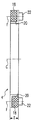
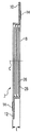
본 발명의 실시 형태로서, 이하 도 1 내지 도 3에 의거하여 갈바니 전지를 설명하기로 한다. 여기서, 도 1은 갈바니 전지(1)의 낱개 부품들 또는 어셈블리들의 분해 사시도이고, 도 2a는 도 1의 평면 Ⅱ를 따른 프레임부의 단면도이며, 도 2b는 도 1의 평면 Ⅱ를 따른 활성부의 단면도이고, 도 3은 도 1의 평면 Ⅲ을 따른 프레임부의 단면도이다. 갈바니 전지(1)는 본 발명의 의미에서의 전기 에너지 저장 셀이다.As an embodiment of the present invention, a galvanic battery will be described below with reference to FIGS. 1 to 3. 1 is an exploded perspective view of individual parts or assemblies of the
도 1의 도시에 따르면, 갈바니 전지(1)는 전기 어셈블리(2), 프레임부(4), 및 2개의 커버 포일들(6)로 구성되는데, 전기 어셈블리는 포일 패키지(8), 음극 집전체 도체(10), 및 양극 집전체 도체(12)를 구비한다. 정향을 위해, 본 도면에는 그 원점이 전방 커버 포일(6)의 중심에 정의되어 있는 좌표축이 표시되어 있다. 전지(1)의 측방 방향은 횡 방향(A)의 중심축에 의해 정의되고, 전지(1)의 수직축은 높이 방향(B)의 중심축에 의해 정의되며, 동시에 전지의 두께 방향이기도 한 전지의 축 방향은 길이 방향(C)의 중심축에 의해 정의된다. 모든 축들은 가는 일점쇄선들로 도시되어 있다. 플러스(positive) 방향이 화살표에 의해 각각 도시되어 있다.According to the illustration of FIG. 1, the
본 도면에서 알 수 있는 바와 같이, 포일 패키지(8)는 대략 플레이트 형태의 윤곽을 갖고, 그 측방 방향(A)으로의 연장이 수직 방향(B)으로의 연장보다 크다. 음극 집전체 도체(10)는 양호한 도체 재료로 제조되고, L형 횡단면을 갖는다. 음극 집전체 도체(10)의 L형 프로파일의 짧은 다리는 포일 패키지(8)의 상부 협폭 측면에 부착된다. 마찬가지로, 양극 집전체 도체(12)도 양호한 도체 재료로 제조되고, L형 횡단면을 가지며, 양극 집전체 도체의 L형 프로파일의 짧은 다리가 포일 패키지(8)의 하부 협폭 측면에 부착된다. 따라서 음극 집전체 도체(10)의 긴 다리는 포일 패키지(8)의 전방 플랫 측면과 동렬로 정렬되어 위쪽(플러스 B 방향)으로 연장되고, 양극 집전체 도체(12)의 긴 다리는 포일 패키지(8)의 후방 플랫 측면과 동렬로 정렬되어 아래쪽(마이너스 B 방향)으로 연장된다. 음극 집전체 도체 및 양극 집전체의 L형 프로파일의 긴 다리들은 두께 방향으로 포일 패키지의 반대쪽을 향한 측면에 전방 또는 후방 커버 포일(6)과의 연결을 위한 가열 실링 테이프(14)의 스트립을 각각 구비한다. 포일 패키지(8)는 본 발명의 의미에서의 활성부를 형성한다는 점을 언급하고자 한다. 집전체 도체들(10, 12)의 재료는 구리, 알루미늄, 또는 기타의 금속이나 그 합금과 같은 공지의 재료들로부터 선택될 수 있다. 접촉의 개선(접촉 저항의 감소) 및/또는 부식의 방지를 위해, 집전체 도체들(10, 12)을 은 또는 금으로 도금할 수 있다.As can be seen in this figure, the
프레임부(4)는 2개의 수직 바들(16)과 2개의 수평 바들(18)을 구비하고, 그들 바들(16, 18)은 일체형 프레임을 형성한다. 프레임의 내부 윤곽은 포일 패키지(8)의 외부 윤곽에 맞춰진다. 상부 수평 바(18)는 횡단면이 L형인 노치(20)를 구비하는데, 그 노치(20)는 안쪽 및 전방 커버 포일(6)을 향한 쪽(플러스 C 방향)으로 두께가 감소한다. 하부 수평 바(18)는 안쪽 및 후방 커버 포일(6)을 향한 쪽(마이너스 C 방향)으로 그 두께가 감소하는 노치(20)를 구비한다. 노치(20)의 형태는 그 노치(20)가 음극 집전체 도체(10) 및 양극 집전체 도체(12)의 L형 프로파일을 수납하도록 하는 크기로 정해진다.The
프레임부(4)가 곧 본 발명의 의미에서의 이음매부이고, 노치(20)를 구비하지 않은 프레임부(4)의 수직 바들(16) 및 수평 바들(18)의 섹션들이 곧 본 발명의 의미에서의 최대 두께의 섹션들이라는 것을 언급하고자 한다. 프레임부(4)의 재료는 전기 전도성이 없고, 축 방향 압력(축 C의 방향으로의) 하에서도 최대 두께의 섹션이 변함없이 전기 어셈블리(2)보다 두꺼워 프레임부(4)가 그 형태를 안정적으로 유지하도록 충분한 압축 강도를 갖는다. 다양한 플라스틱들, 세라믹들, 및 기술적 유리들이 그 재료로서 적당하다.The
프레임부(4)의 전방 플랫 측면(플러스 C 방향)에서 최대 두께의 섹션들에 센터링 니플들(22)을 구비하는데, 그 센터링 니플들(22)은 커버 포일들(6)에 있는 센터링 구멍들(24)과 동렬로 정렬된다. 알아보기 쉽게 하기 위해, 본 도면에는 센터링 니플들(22)과 센터링 구멍들(24)의 축들(F, F')이 셀(1)의 좌측(마이너스 A 방향)에 도시되어 있다. 도 2A 및 도 2B에는, 프레임부(4) 또는 전기 어셈블리(2)가 축들 B와 C에 의해 펼쳐지는(축 방향의 중심 평면에 수직으로) 평면 Ⅱ를 따른 단면도로 도시되어 있다. 도시된 바와 같이, 프레임부(4)는 그 최대 두께의 섹션들에서 전기 어셈블리(2)의, 특히 포일 패키지(8)의 두께(t)보다 큰 두께(T)를 갖는다. 도 2B에는, 음극 측의 집전체 포일들(음극 집전체 포일들)(26)이 음극 집전체 도체(10)와 연결되고, 교대로 양극 측의 집전체 포일들(양극 집전체 포일들)(28)이 양극 집전체 도체(12)와 연결되는 구조가 포일 패키지(8)의 영역에 개략적으로 도시되어 있다. 포일 스택(8) 내에서 그 사이에 배치되는 음극 측과 양극 측의 화학적 활성 재료의 포일들 및 분리막 포일들은 알아보기 쉽게 하기 위해 본 도면에서 생략되어 있다.Centering
도 3은 평면 Ⅱ와 평행하게 놓이고 2개의 좌측 센터링 구멍들(24) 및 센터링 니플들(22)을 통해 연장되는(도 1의 축들 F, F', E 참조) 도 1의 평면 Ⅲ을 따른 프레임부(4)의 단면도를 도시하고 있다. 본 단면도는 정의에 따라 프레임부(4)의 좌측 수직 바(16)를 통해 연장되는데, 그러나 상부 및 하부 영역은 임의로 각각의 수직 바(18)에 할당될 수도 있다. 알 수 있는 바와 같이, 센터링 니플(22)과 동렬로 정렬되어 관통 구멍(30)이 각각 연장되고, 센터링 니플(22)과 대향된 프레임부(4)의 플랫 측면에 리세스(32)가 각각 마련되는데, 리세스(32)는 그것이 센터링 니플(22)을 수납할 수 있도록 그 크기가 정해진다.FIG. 3 along plane III of FIG. 1 lying parallel to plane II and extending through two left centering
셀(1)(도 1을 참조)의 조립을 위해, 음극 집전체 도체(10) 및 양극 집전체 도체(12)의 L형 프로파일들이 프레임부(4)의 노치들(20)에 착석하도록 전기 어셈블리(2)를 프레임부(4)에 끼워 넣는다. 그를 위해서는, 예컨대 양극 집전체 도체(12)를 프레임부(4)의 개구부를 통과하여 이송하기 위해 먼저 전기 어셈블리(2)와 프레임부(4)를 서로 기울여야 함을 알 수 있다. 전기 어셈블리(2)를 프레임부(4)에 끼워 넣는 즉시, 전방 커버 포일(6)의 센터링 구멍들(24)을 프레임부(4)의 센터링 니플들(22)에 맞춰 정향하여 그에 끼우고, 예컨대 적절한 접착, 용접, 또는 기타의 접합 방법들에 의해 전방 커버 포일(6)을 프레임부(4)에 밀봉 연결한다. 이때, 음극 집전체 도체(10) 상의 가열 실링 테이프(14)의 스트립은 음극 집전체 도체(10)와 커버 포일(6) 사이를 연결하는 역할을 한다. 끝으로, 후방 커버 포일(6)을 프레임부(4)의 후방 플랫 측면 상에 씌우는데, 센터링 구멍들(24)을 리세스들(32)과 동렬로 정렬하여 전방 커버 포일(6)과 동일하게 프레임부(4)와 양극 집전체 도체(12)와 연결한다.For assembly of the cell 1 (see FIG. 1), the L-shaped profiles of the negative electrode
도 4는 조립된 상태에 있는 본 발명의 제2 실시 형태에 따른 갈바니 전지(1')의 사시도를 도시하고 있다. 제2 실시 형태의 갈바니 전지(1')는 그 구조에 있어 전술된 제1 실시 형태의 셀(1)과 동일하고, 집전체 도체들(10, 12)이 긴 협폭 측면들 대신에 전지(1')의 짧은 협폭 측면들로부터 연장된다는 점에서만 상이하다.4 shows a perspective view of a galvanic cell 1 'according to a second embodiment of the present invention in an assembled state. The
본 발명의 제3 실시 형태로서, 이하 도 5 내지 도 8에 의거하여 셀 블록(34)을 설명하기로 한다. 여기서, 도 5는 셀 블록(34)의 낱개 부품들 또는 어셈블리들의 분해 사시도이고, 도 6은 셀 블록(34)의 몇몇 어셈블리들을 다른 시선 방향으로부터 바라본 확대도이며, 도 7은 조립 상태에 있는 셀 블록(34)의 사시도이고, 도 8은 도 7의 세부 Ⅷ의 확대도이다.As a third embodiment of the present invention, the
도 5에 도시된 바와 같이, 셀 블록(34)은 제1 실시 형태의 10개의 개별 갈바니 전지들(1i 내지 1x), 4개의 나사들(36), 8개의 와셔들(38), 및 4개의 너트들(40)로 구성된다. 이때, 각각의 짝수 전지(1ii 내지 1x)는 도 1의 도시와 상응하는 바와 같이 배치된다. 즉, 짝수 전지들(1ii 내지 1x)에서는, 음극 집전체 도체(10)가 도면의 위쪽에서 도면 관찰자를 향한 측면에 위치하는 한편, 양극 집전체 도체(12)가 셀 블록의 아래쪽에서 도면 관찰자의 반대쪽을 향한 측면에 위치한다(도면에서, 아래쪽에 놓인 짝수 전지들((1ii 내지 1x)의 양극 집전체 도체(12)는 그 앞에 놓인 셀들에 의해 가려져 있음). 그 반면에, 홀수 전지들(1i 내지 1ix)은 도 1의 도시에 대해 축 C를 중심으로 180°회전한 정향으로 배치된다. 즉, 그 전지들에서는, 양극 집전체 도체(12)가 셀 블록의 위쪽에서 도면 관찰자의 반대쪽을 향한 전지의 측면에 위치하는 한편, 음극 집전체 도체(10)가 셀 블록의 아래쪽에서 도면 관찰자를 향한 전지의 측면에 위치한다. 그와 같이 하여, 홀수 전지, 예컨대 전지 1i의 양극 집전체 도체(12)가 스태킹 방향으로 다음 짝수 전지, 즉 선택된 예에서의 전지 1ii의 음극 집전체 도체(10)와 직접 마주하게 된다. 그러한 짝수 전지 1ii의 음극 집전체 도체(10)와 다음 홀수 전지, 즉 본 예에서의 전지 1iii의 양극 집전체 도체(12) 사이에는 대략 2개의 프레임부(4)의 두께의 간격이 형성된다. 짝수 전지 1ii의 양극 집전체 도체(12)는 셀 블록의 하측에서 스태킹 방향으로 다음 홀수 전지, 즉 본 예에서의 전지 1iii의 음극 집전체 도체(10)와 직접 마주하게 된다. 역시, 그 홀수 전지 1iii의 음극 집전체 도체(10)와 다음 짝수 전지 1iv 사이에는 대략 2개의 프레임부(4)의 두께의 간격이 형성되게 된다. 그것은 마지막 전지들 1ix, 1x에까지 계속된다. 환언하면, 전지들의 서수들 1i 내지 1x가 증가하는 방향으로, 양극 집전체 도체(12)와 음극 집전체 도체(10)가 스태킹 방향으로 각각 서로 직접 마주하는 한편, 그 음극 집전체 도체(10)와 다음 양극 집전체 도체(12) 사이에 뚜렷한 간격이 형성된다. 첫 번째 전지 1i의 경우에 스택(32)의 전방 단부 면에서 음극 집전체 도체(10)에 출입 가능한 한편, 마지막 전지 1x의 경우에 전지 스택(34)의 후방 단부 면에서 양극 집전체 도체(12)에 출입 가능하다는 것을 또한 언급하고자 한다.As shown in FIG. 5, the
더 알 수 있는 바와 같이, 나사들(36)은 개별 전지들(1)의 프레임부(4)의 관통 구멍들(30) 및 커버 포일들(6)의 관통 구멍들(24)을 통해 연장되고(예컨대 도 5의 축들 F, F' 참조), 와셔들(38)을 매개로 하여 너트들(40)에 의해 고정된다.As can be appreciated, the
본 발명의 필수적인 특징들을 구체적인 실시예들을 참조하여 전술하였지만, 본 발명은 그 실시예들에 한정되는 것이 아니라, 특허 청구 범위에 의해 주어지는 범위 및 영역 내에서 변형될 수 있는 것임을 이해하여야 할 것이다.While the essential features of the invention have been described above with reference to specific embodiments, it should be understood that the invention is not limited to the embodiments, but may be modified within the scope and scope of the claims.
즉, 예컨대 제3 실시 형태의 셀 블록(34)의 전지들은 나사들, 와셔들, 및 너트들에 의해 클램핑된다. 그러나 그러한 고정 방식은 단지 예시적인 것에 지나지않고, 예컨대 경우에 따라 적절한 압력 플레이트를 매개로 한 리벳 접함도 가능하다는 것을 알아야 할 것이다. 그러나 전지 스택(34)의 수월한 분해를 원할 경우에는 나사 결합이 바람직한 반면, 결합 또는 클램핑의 분리가 거의 일어날 수 없는 적용 사안들에서는 예컨대 전술된 리벳 접합과 같은 분리 불가한 결합이 선호될 수 있다.That is, for example, the batteries of the
전지들(1)의 프레임 형태의 시일 이음매들에 있는 관통 구멍들을 통해 연장되는 텐션 요소들에 의한 전지 스택의 클램핑은 도 역시 단지 예시적인 것으로 이해되어야 한다. 클램핑은 외부로부터 인가되는 클램프들 또는 고정 링들에 의해 이뤄질 수도 있다.The clamping of the cell stack by the tension elements extending through the through holes in the seal seams in the frame form of the
도 1에 도시된 프레임부(4)의 형태도 역시 일례에 지나지 않는다. 본 발명의 작용 방식에 있어 본질적인 사항은 파우치 전지의 시일 이음매가 프레임 형태로 형성되어 전지의 활성부를 둘러싸고, 적어도 외부로부터 전지로 축 방향 압력이 예상되는 지점에서 활성부 그 자체보다 더 두껍게 된다는데 있다.The shape of the
전기 어셈블리(2), 즉 도 1 및 도 2B의 전기 패키지(8)와 집전체 도체들(10, 12)의 구조와 형태도 하나의 예에 불과할 뿐이고, 요건에 맞춰 구성될 수 있다. 집전체 도체들(10, 12)이 다른 프로파일을 가질 수도 있고, 전극들(26, 28)의 수가 전적으로 임의로 설정된다. 집전체 도체들(10, 12)과 관련된 변형들의 예들이 도 9 내지 도 12에 도시되어 있다.The structure and shape of the
즉, 집전체 도체들(10, 12)의 위치가 요건에 따라 변할 수 있다. 예컨대, 도 9 또는 도 10에 도시된 바와 같이, 2개의 집전체 도체들(10, 12)을 셀의 협폭 측면들 중의 하나에 수용하는 것을 생각해볼 수 있다. 그것은 집전체 도체들이 손상을 받음이 없이 셀들이 그 하면으로써 세워질 수 있다는 이점을 갖는다. 제4 실시 형태의 셀에서는, 도 9의 도시에 따라 음극 집전체 도체(10)와 양극 집전체 도체(12)가 대향된 플랫 측면들에 배치되는 반면에, 제5 실시 형태에 따른 셀에서는 도 10의 도시에 따라 상부 협폭 측면의 중앙에 서로 동렬로 정렬된다. 그 경우, 연결은 적절히 형성된 접촉 단자들을 통해 이뤄진다.That is, the position of the
제6 실시 형태가 도 11에 도시되어 있다. 그 실시 형태에서도, 2개의 집전체 도체들(10, 12)의 자유 단부들이 전기 어셈블리(2)의 협폭 측면들을 따라 연장되지만, 대향된 플랫 측면들과 동렬로 정렬되어 전폭에 걸쳐 연장된다. 이때, 집전체 도체들 중의 하나(여기서는 음극 집전체 도체(10))는 전체 포일 스택(8)의 둘레에 걸쳐 맞물린다. 본 실시 형태에 따른 배열은 스택에서 셀들을 방향을 바꿔가면서 배열함으로써 서로 직접 이웃한 집전체 도체들과의 직렬 접속이 구현될 수 있다는 이점을 갖는다.A sixth embodiment is shown in FIG. In that embodiment too, the free ends of the two
도 12의 도시에 따른 제7 실시 형태의 경우에도, 이전의 실시 형태에서와 같은 접속이 가능하지만, 다만 집전체 도체들(10, 12) 중의 하나가 포일 스택(8)의 둘레에 맞물리는 것이 회피된다. 본 실시 형태에서는, L형 횡단면을 갖는 2개의 집전체 도체들(10, 12)이 포일 스택(8)의 동일한 협폭 측면에 배치되는데, 집전체 도체들(10, 12)의 L형 프로파일의 포일 스택(8)을 향한 다리의 부분에는 서로 톱니식으로 노치가 각각 형성된다. 본 도면에서의 음극 집전체 도체(10)는 단지 프로파일 횡단면을 알아보기 쉽게 하기 위해 파단된 채로 도시되어 있음을 언급하고자 한다. 실제로, 음극 집전체 도체(10)도 역시 단절 없는 프로파일 부품이다.Also in the case of the seventh embodiment according to the illustration of FIG. 12, the same connection as in the previous embodiment is possible, except that one of the
제8 실시 형태가 도 13에 도시되어 있다. 본 도면은 도 3의 도시에 해당하는데, 다만 프레임부(4)의 상부 절반만이 도시되어 있다. 본 실시 형태에서는, 센터링 니플들(22) 대신에 센터링 슬리브들(42)이 마련되고, 그 센터링 슬리브들(42)은 구멍들(44)에 삽입된다. 이때, 센터링 슬리브들(42)은 제1 실시 형태(도 3을 참조)의 센터링 니플들(22) 및 관통 구멍들(30)의 기능을 떠맡고, 구멍들(44)은 센터링 슬리브들(42)을 수납하는 것에 추가하여 제1 실시 형태의 리세스들(32)의 역할을 한다. 셀들(1)을 별개의 관통 구멍들을 통해 또는 특히 바깥에 놓인 요소들을 통해 클램핑할 경우에는, 슬리브들 대신에 센터링 핀들을 사용할 수 있다(도시를 생략함).An eighth embodiment is shown in FIG. This figure corresponds to the illustration of FIG. 3, but only the upper half of the
제4 내지 제8 실시 형태는 제1 또는 제2 실시 형태의 변형들을 형성한다. 제1 또는 제2 실시 형태에 관한 설명은 변형에 의해 배제되지 않는 한 제4 내지 제8 실시 형태에도 예외없이 적용된다.The fourth to eighth embodiments form variants of the first or second embodiment. The description relating to the first or second embodiment also applies without exception to the fourth to eighth embodiments unless excluded by modification.
본 발명은 전기 에너지를 저장하고 전달하는 모든 타입의 저장 셀들, 특히 임의의 타입의 전기 화학적 1차 전지들 및 2차 전지들에 적합하다. 본 발명은 평판형 구조의 리튬 이온 전지들 및 그들로 구성된 셀 블록들에 적용되는 것이 매우 바람직하다.The present invention is suitable for all types of storage cells that store and deliver electrical energy, in particular any type of electrochemical primary cells and secondary cells. The present invention is very preferably applied to lithium ion batteries having a planar structure and cell blocks composed thereof.
전술된 설명에 따른 셀 블록은 첫 번째 또는 마지막 셀(1i, 1x)의 자유 집전체 도체(10, 12)와 연결되는 접속 전극 단자들 및 선택적인 하우징과 함께 배터리 또는 축전지를 형성하고, 그러한 배터리 또는 축전지는 차량 또는 내장 전기 시스템에의 급전 또는 전기 구동을 위한 다른 기술적 용도들에 사용될 수 있다. 그러한 배터리 또는 축전지는 본 발명의 의미에서의 전기 에너지 저장 장치이다.The cell block according to the above description forms a battery or a battery together with connecting electrode terminals and an optional housing connected with the free
1, 1': 갈바니 전지 2: 전기 어셈블리
4: 프레임부(이음매부) 6: 커버 포일(포일부)
8: 포일 패키지(활성부) 10: 음극 집전체 도체
12: 양극 집전체 도체 14: 가열 실링 테이프
16: 수직 바 18: 수평 바
20: 노치 22: 센터링 니플
24: 센터링 구멍 26: 음극 집전체 포일
28: 양극 집전체 포일 30: 관통 구멍
32: 리세스 34: 셀 블록
36: 원통형 나사 38: 와셔
40: 너트 42: 센터링 슬리브
44: 구멍 101: (선행 기술: 셀 스택)
102: (선행 기술: 셀) 103: (선행 기술: 접점 플래그)
104: (선행 기술: 베이스 플레이트) A: 횡 방향 중심축(선행 기술: 음극)
B: 높이 방향 중심축 C: 길이 방향 수평 중심축
D, D': 24를 통한 측방 방향 수평축 E: 24를 통한 수직축
F, F': 22, 24를 통한 길이 방향 수평축들
i 내지 x: 1의 지수 Ⅱ: 평면 B-C
Ⅲ: 평면 E-F/F' K: (선행 기술: 양극)
t: 2의 전부에 걸친 두께 T: 4의 전부에 걸친 두께
상기 부호의 설명은 상세한 설명의 통합된 구성 요소라는 점을 명시적으로 언급하고자 한다.1, 1 ': galvanic cell 2: electrical assembly
4: frame part (seam part) 6: cover foil (foil part)
8: Foil package (active part) 10: Negative current collector conductor
12: positive electrode current collector conductor 14: heating sealing tape
16: vertical bar 18: horizontal bar
20: notch 22: centering nipple
24: centering hole 26: negative electrode current collector foil
28: anode current collector foil 30: through hole
32: recess 34: cell block
36: cylindrical screw 38: washer
40: nut 42: centering sleeve
44: hole 101: (prior art: cell stack)
102: (prior art: cell) 103: (prior art: contact flag)
104: (prior art: base plate) A: transverse center axis (prior art: cathode)
B: Central axis in the height direction C: Horizontal axis in the longitudinal direction
D, D ': Lateral horizontal axis through 24 E: Vertical axis through 24
F, F ': longitudinal horizontal axes through 22, 24
index II of i to x: 1 plane BC
III: Planar EF / F 'K: (Prior Art: Anode)
t: thickness over all of 2 T: thickness over all of 4
It is intended that the description of the above signs be an integral part of the detailed description.
Claims (35)
활성부와 연결되고, 외부로부터 전류를 활성부에 공급하고 활성부로부터 나오는 전류를 외부로 전달하도록 배치 및 구성되는 적어도 2개의 집전체 도체들; 및
대략 직육면체 형태의 윤곽에 의해 프리즘 모양의 기본 형태를 그리고, 활성부를 가스 및 액체가 새지 않게 덮어싸되, 셀의 프리즘 모양의 기본 형태의 두께 방향으로의 연장이 나머지 2개의 공간 방향들로의 연장보다 훨씬 작고, 바람직하게는 2개의 나머지 공간 방향들 중의 하나의 방향으로의 연장이 2개의 나머지 공간 방향들 중의 다른 하나의 방향으로의 연장보다 큰 외장 덮개를 구비하는 전기 에너지 저장 셀에 있어서,
외장 덮개는 2개의 납작한 포일부들 및 포일부들의 에지들을 연결하는 둘레 방향 이음매부를 구비하되,
이음매부는 활성부를 프레임 형태로 둘러싸고, 기계적 압력 하에서도 두께가 변함없이 활성부의 두께보다 더 크게 되는 최대 두께의 섹션들을 구비하는 것을 특징으로 하는 전기 에너지 저장 셀.An active part disposed and configured to store electrical energy supplied from the outside and deliver the stored energy to the outside;
At least two current collector conductors connected to the active portion and arranged and configured to supply a current from the outside to the active portion and to transfer current from the active portion to the outside; And
The prismatic shape is outlined by a substantially rectangular parallelepiped contour, and the active part is covered freely of gas and liquid, with the extension of the cell in the thickness direction of the prismatic shape of the cell more than in the remaining two spatial directions. In an electrical energy storage cell having a sheathing cover which is much smaller and preferably has an extension in one of the two remaining spatial directions greater than an extension in the other of the two remaining spatial directions,
The sheathing cover has two flat foil portions and a circumferential seam connecting the edges of the foil portions,
The seam is characterized in that it comprises a section of the largest thickness which encloses the active part in the form of a frame and which is thicker than the thickness of the active part, even under mechanical pressure.
Applications Claiming Priority (2)
| Application Number | Priority Date | Filing Date | Title |
|---|---|---|---|
| DE102009011524.2 | 2009-03-03 | ||
| DE102009011524A DE102009011524A1 (en) | 2009-03-03 | 2009-03-03 | Electric energy storage cell and cell block, electric energy storage device and vehicle with it |
Publications (1)
| Publication Number | Publication Date |
|---|---|
| KR20120006992A true KR20120006992A (en) | 2012-01-19 |
Family
ID=42138995
Family Applications (1)
| Application Number | Title | Priority Date | Filing Date |
|---|---|---|---|
| KR1020117023177A KR20120006992A (en) | 2009-03-03 | 2010-02-26 | Electrical energy storage cell and cell block, electrical energy storage device and the vehicle comprising the same |
Country Status (8)
| Country | Link |
|---|---|
| US (1) | US20120196174A1 (en) |
| EP (1) | EP2404338B1 (en) |
| JP (1) | JP2012519362A (en) |
| KR (1) | KR20120006992A (en) |
| CN (1) | CN102714282A (en) |
| BR (1) | BRPI1009113A2 (en) |
| DE (1) | DE102009011524A1 (en) |
| WO (1) | WO2010099906A2 (en) |
Families Citing this family (26)
| Publication number | Priority date | Publication date | Assignee | Title |
|---|---|---|---|---|
| JP5439099B2 (en) * | 2009-09-16 | 2014-03-12 | Udトラックス株式会社 | Power storage device and power storage module |
| US8795872B2 (en) | 2010-07-26 | 2014-08-05 | Enerdel, Inc. | Battery cell system with interconnected frames |
| DE102010045700A1 (en) * | 2010-09-16 | 2012-03-22 | Li-Tec Battery Gmbh | Electrochemical energy storage device with flat cells and spacers |
| DE102010050981A1 (en) * | 2010-11-10 | 2012-05-10 | Daimler Ag | Battery with a cell group |
| DE102011011432A1 (en) * | 2011-02-16 | 2012-08-16 | Francesco Furlanetto | Cell i.e. rectangular-shaped galvanic cell, for e.g. lithium ion battery of electric car, has connecting part detachably connected with support and mechanically or electrical conductively connecting cell with another cell |
| ITTO20110235A1 (en) * | 2011-03-16 | 2012-09-17 | Bitron Spa | POSITIONING SYSTEM FOR BATTERY MODULES. |
| JP5484426B2 (en) * | 2011-10-26 | 2014-05-07 | 豊田合成株式会社 | Battery module and battery unit |
| DE102012011083A1 (en) * | 2012-06-02 | 2013-12-05 | Audi Ag | Memory element comprising a plurality of lithium cells |
| US9196878B2 (en) * | 2012-11-20 | 2015-11-24 | GM Global Technology Operations LLC | Stackable cartridge module design |
| DE102013203094A1 (en) | 2013-02-26 | 2014-09-11 | Robert Bosch Gmbh | Battery cell with a prismatic housing, battery module and motor vehicle |
| DE102013213550A1 (en) | 2013-07-11 | 2015-01-15 | Robert Bosch Gmbh | Battery cell with a prismatic or cylindrical housing, battery module and motor vehicle |
| CN104183863B (en) * | 2014-08-07 | 2017-01-11 | 长丰集团有限责任公司 | Soft-packing lithium ion battery module |
| KR102394696B1 (en) * | 2015-08-20 | 2022-05-06 | 삼성에스디아이 주식회사 | Secondary Battery And Fabricating Method Thereof |
| KR102066197B1 (en) * | 2015-12-09 | 2020-01-14 | 주식회사 엘지화학 | Battery module and battery pack including the same |
| DE102015225405A1 (en) * | 2015-12-16 | 2017-06-22 | Bayerische Motoren Werke Aktiengesellschaft | Energy supply cell |
| EP3482436A4 (en) * | 2016-07-05 | 2020-03-18 | Ammon N. Balaster | Modular power storage and supply system |
| DE102016214239A1 (en) * | 2016-08-02 | 2018-02-08 | Robert Bosch Gmbh | Film stack for a battery cell and method of manufacture |
| JP6620944B2 (en) * | 2016-11-28 | 2019-12-18 | トヨタ自動車株式会社 | Laminated battery and battery pack for series connection |
| DE102018207332A1 (en) * | 2018-05-09 | 2019-11-14 | Bayerische Motoren Werke Aktiengesellschaft | Memory cell for a memory device of a motor vehicle, memory device and motor vehicle |
| CN109860684B (en) * | 2019-01-28 | 2023-10-10 | 东莞市天蓝智能装备有限公司 | Stereoscopic warehouse type intelligent capacity-dividing and formation equipment |
| DE102019103169A1 (en) * | 2019-02-08 | 2020-08-13 | Dr. Ing. H.C. F. Porsche Aktiengesellschaft | Cell module with rotationally invariant attachment points |
| US11563257B2 (en) * | 2019-11-14 | 2023-01-24 | The Boeing Company | Structurally cross-tied energy cell |
| US11387500B2 (en) | 2019-11-14 | 2022-07-12 | The Boeing Company | Multi-tab battery cycle life extension through alternating electrode charging |
| EP4120444A1 (en) * | 2020-03-13 | 2023-01-18 | Dai Nippon Printing Co., Ltd. | Electricity storage device, electricity storage device assembly, and moving body |
| WO2022047791A1 (en) * | 2020-09-07 | 2022-03-10 | 宁德时代新能源科技股份有限公司 | Battery cell, battery, and power consuming device |
| DE102021205502A1 (en) | 2021-05-31 | 2022-12-01 | Volkswagen Aktiengesellschaft | Battery cell for a vehicle battery |
Family Cites Families (14)
| Publication number | Priority date | Publication date | Assignee | Title |
|---|---|---|---|---|
| JPH07282841A (en) | 1994-04-05 | 1995-10-27 | Mitsubishi Chem Corp | Lithium ion secondary battery |
| JP2000048773A (en) * | 1998-07-27 | 2000-02-18 | Japan Storage Battery Co Ltd | Non-aqueous electrolyte cell |
| WO2001037353A1 (en) * | 1999-11-15 | 2001-05-25 | Eveready Battery Company, Inc. | Durable high density power supply |
| EP1475852B1 (en) | 2003-05-05 | 2017-01-11 | Enax, Inc. | Lead outlet structure of secondary battery in sheet type |
| JP3972884B2 (en) * | 2003-10-10 | 2007-09-05 | 日産自動車株式会社 | Assembled battery |
| JP4426861B2 (en) | 2004-02-04 | 2010-03-03 | エナックス株式会社 | Thin secondary battery cell, method for manufacturing the same, and secondary battery module |
| JP4457812B2 (en) * | 2004-08-30 | 2010-04-28 | 新神戸電機株式会社 | Battery pack and module battery |
| US9653748B2 (en) * | 2005-04-14 | 2017-05-16 | Enerdel, Inc. | Apparatus and method for securing battery cell packs |
| KR100880386B1 (en) * | 2005-06-03 | 2009-01-23 | 주식회사 엘지화학 | Secondary Battery of Novel Structure and Battery Pack Having the Same |
| JP4890795B2 (en) * | 2005-06-16 | 2012-03-07 | 日本電気株式会社 | Film exterior battery and assembled battery in which it is assembled |
| JP4904863B2 (en) * | 2006-03-15 | 2012-03-28 | 日産自動車株式会社 | Battery module and manufacturing method thereof |
| US20100200314A1 (en) | 2007-04-24 | 2010-08-12 | Peter Birke | Energy storage assembly with poka-yoke connections |
| JP5236210B2 (en) * | 2007-05-10 | 2013-07-17 | カルソニックカンセイ株式会社 | Battery module structure of the battery |
| DE102008010814B4 (en) * | 2008-02-23 | 2014-04-30 | Daimler Ag | Single cell for a battery and its use |
-
2009
- 2009-03-03 DE DE102009011524A patent/DE102009011524A1/en not_active Withdrawn
-
2010
- 2010-02-26 CN CN2010800104392A patent/CN102714282A/en active Pending
- 2010-02-26 KR KR1020117023177A patent/KR20120006992A/en not_active Application Discontinuation
- 2010-02-26 JP JP2011552349A patent/JP2012519362A/en active Pending
- 2010-02-26 EP EP10706161.6A patent/EP2404338B1/en not_active Not-in-force
- 2010-02-26 WO PCT/EP2010/001218 patent/WO2010099906A2/en active Application Filing
- 2010-02-26 US US13/254,092 patent/US20120196174A1/en not_active Abandoned
- 2010-02-26 BR BRPI1009113A patent/BRPI1009113A2/en not_active IP Right Cessation
Also Published As
| Publication number | Publication date |
|---|---|
| JP2012519362A (en) | 2012-08-23 |
| CN102714282A (en) | 2012-10-03 |
| WO2010099906A2 (en) | 2010-09-10 |
| DE102009011524A1 (en) | 2010-09-09 |
| EP2404338B1 (en) | 2015-09-16 |
| BRPI1009113A2 (en) | 2016-03-01 |
| WO2010099906A3 (en) | 2010-10-28 |
| EP2404338A2 (en) | 2012-01-11 |
| US20120196174A1 (en) | 2012-08-02 |
Similar Documents
| Publication | Publication Date | Title |
|---|---|---|
| KR20120006992A (en) | Electrical energy storage cell and cell block, electrical energy storage device and the vehicle comprising the same | |
| US9331320B2 (en) | Large format electrochemical energy storage device housing and module | |
| JP5456254B2 (en) | Secondary battery pack having an alternating orientation configuration | |
| US8486557B2 (en) | Battery module of improved welding reliability and battery pack employed with the same | |
| KR100873308B1 (en) | High Capacity Battery Cell Employed with Two or More Unit Cells | |
| KR101051483B1 (en) | Electrode terminal connection member of battery module | |
| KR101305224B1 (en) | Battery Module and Battery Pack Comprising the Same | |
| US11289776B2 (en) | Battery module having bus bar assembly | |
| US7524216B2 (en) | Three-dimensional electrode terminal for pouch-typed battery | |
| US9692023B2 (en) | Electricity storage module | |
| KR101326182B1 (en) | Battery Module Based upon Unit Module Having External Covering Member and Cartridge | |
| CN109103402B (en) | Wire connection bus bar and conductive module | |
| KR102212449B1 (en) | Battery module and battery pack including the same | |
| US20200058918A1 (en) | Battery Module, and Battery Pack and Vehicle Comprising Same | |
| US20130280590A1 (en) | Electrochemical energy storage device with flat cells and spacing elements | |
| US20130027840A1 (en) | Energy storage module | |
| US8415048B2 (en) | Battery and battery pack comprising the same | |
| KR20120074426A (en) | Unit module of novel structure and battery module comprising the same | |
| CN115315847A (en) | Battery block | |
| CN214384783U (en) | Electric connector, battery pack and battery pack | |
| US20200083496A1 (en) | Rechargeable battery subunit and rechargeable battery |
Legal Events
| Date | Code | Title | Description |
|---|---|---|---|
| WITN | Application deemed withdrawn, e.g. because no request for examination was filed or no examination fee was paid |