KR20120000540A - Apparatus and method of resource allocation for channel in relay system - Google Patents
Apparatus and method of resource allocation for channel in relay system Download PDFInfo
- Publication number
- KR20120000540A KR20120000540A KR1020110061889A KR20110061889A KR20120000540A KR 20120000540 A KR20120000540 A KR 20120000540A KR 1020110061889 A KR1020110061889 A KR 1020110061889A KR 20110061889 A KR20110061889 A KR 20110061889A KR 20120000540 A KR20120000540 A KR 20120000540A
- Authority
- KR
- South Korea
- Prior art keywords
- pdcch
- channel
- common
- prb
- phich
- Prior art date
Links
Images


Classifications
-
- H—ELECTRICITY
- H04—ELECTRIC COMMUNICATION TECHNIQUE
- H04B—TRANSMISSION
- H04B7/00—Radio transmission systems, i.e. using radiation field
- H04B7/14—Relay systems
- H04B7/15—Active relay systems
- H04B7/155—Ground-based stations
- H04B7/15528—Control of operation parameters of a relay station to exploit the physical medium
- H04B7/15542—Selecting at relay station its transmit and receive resources
-
- H—ELECTRICITY
- H04—ELECTRIC COMMUNICATION TECHNIQUE
- H04J—MULTIPLEX COMMUNICATION
- H04J11/00—Orthogonal multiplex systems, e.g. using WALSH codes
-
- H—ELECTRICITY
- H04—ELECTRIC COMMUNICATION TECHNIQUE
- H04W—WIRELESS COMMUNICATION NETWORKS
- H04W72/00—Local resource management
- H04W72/04—Wireless resource allocation
- H04W72/044—Wireless resource allocation based on the type of the allocated resource
- H04W72/0453—Resources in frequency domain, e.g. a carrier in FDMA
Abstract
Description
본 발명은 OFDMA(Orthogonal Frequency Division Multiple Access) 방식의 릴레이(relay) 시스템에 관한 것으로, 더욱 상세하게는 릴레이 시스템에서 릴레이(RN: Relay Node) 및 단말(UE: User Equipment)에 대한 제어 정보 전송을 위해 사용되는 기지국(eNB: e-UTRAN NodeB)의 하향링크 백홀 서브프레임의 효율적인 자원 할당에 관한 것이다.The present invention relates to a relay system of an orthogonal frequency division multiple access (OFDMA) scheme, and more particularly, to transmit control information for a relay node (RN) and a user equipment (UE) in a relay system. The present invention relates to efficient resource allocation of a downlink backhaul subframe of an e-UTRAN NodeB (eNB).
본 발명은 지식경제부의 차세대통신네트워크산업원천기술개발사업의 일환으로 수행한 연구로부터 도출된 것이다. [과제관리번호: 10035300, 과제명: Multi-hop Relay 기술개발]. The present invention is derived from a study performed as part of the next generation communication network industrial source technology development project of the Ministry of Knowledge Economy. [Task management number: 10035300, Assignment name: Multi-hop Relay technology development].
최근 이동통신 시스템에서 처리율, 레이턴시 및 커버리지 측면의 성능 향상을 위한 통신 표준들이 개발되고 있다. 현재 폭넓게 사용되고 있는 표준은 3세대(3G) 이동통신 시스템의 일부로서 개발되었으며, 3GPP(3rd Generation Partnership Project)에 의해 유지되는 UMTS(Universal Mobile Telecommunications System)이다. 이 중에서 특히 3GPP LTE(Long Term Evolution)는 UMTS 시스템에서의 높은 데이터율, 낮은 지연(latency), 패킷 최적화된 시스템 성능 및 넓은 커버리지를 달성하기 위해 3GPP에 의해 주도되는 통신 표준이다.Recently, communication standards for improving performance in terms of throughput, latency, and coverage have been developed in mobile communication systems. A widely used standard is the UMTS (Universal Mobile Telecommunications System) which was developed as part of the 3rd generation (3G) mobile communication system and is maintained by the 3rd Generation Partnership Project (3GPP). Among these, 3GPP Long Term Evolution (LTE) is a communication standard driven by 3GPP to achieve high data rate, low latency, packet optimized system performance and wide coverage in UMTS systems.
LTE-Advanced(4세대 이동통신) 시스템에서는, 이동통신 시스템에서는 보다 높은 전송률을 지원하고 서비스 가능한 영역(coverage)을 확장하기 위해 기지국과 단말 간의 직접적인 통신 방식뿐만이 아니라 릴레이(RN) 시스템을 이용한 신호 전달 방식이 연구되고 있다. 이 기술은 릴레이를 통해 기지국과 단말 사이의 경로에서 신호를 중계함으로써 경로 손실을 줄여 고속 데이터 통신을 가능케 하며, 기지국으로부터 멀리 떨어진 이동 단말로도 신호를 전달함으로써 서비스 영역을 확장할 수 있다.In LTE-Advanced (4th generation mobile communication) system, a signal transmission using a relay (RN) system as well as a direct communication method between a base station and a terminal in order to support a higher data rate and expand the serviceable coverage in a mobile communication system The method is being studied. This technology enables high-speed data communication by reducing the signal loss by relaying signals in the path between the base station and the terminal through a relay, and extends the service area by transmitting a signal to a mobile terminal far from the base station.
LTE-Advanced 이동통신 시스템의 릴레이는 셀 내의 음영 지역 해소를 목적으로 사용되며, 셀 경계 지역에 설치되어 효과적인 셀 커버리지 확장과 Throughput을 향상시킬 목적으로 사용된다. 기지국에서 단말로 전송되는 하향링크의 물리계층 신호는 PDSCH(Physical Downlink Shared Channel), PDCCH(Physical Downlink Control Channel), PCFICH(Physical Control Format Indicator Channel), PHICH(Physical Hybrid ARQ Indicator Channel) 등이 있다. 또한 단말에서 기지국으로 전송되는 상향링크의 물리계층 신호는 PUSCH(Physical Uplink Shared Channel), PUCCH(Physical Uplink Control Channel), SRS(Sounding Reference Signal) 등이 있다. The relay of the LTE-Advanced mobile communication system is used for the purpose of eliminating the shadow area in the cell, and is installed in the cell boundary area to improve the effective cell coverage and throughput. The downlink physical layer signals transmitted from the base station to the terminal include a physical downlink shared channel (PDSCH), a physical downlink control channel (PDCCH), a physical control format indicator channel (PCFICH), and a physical hybrid ARQ indicator channel (PHICH). In addition, the uplink physical layer signal transmitted from the terminal to the base station includes a PUSCH (Physical Uplink Shared Channel), a PUCCH (Physical Uplink Control Channel), SRS (Sounding Reference Signal).
LTE-Advanced 이동통신 시스템에서 기지국은 하향링크를 통해 단말로 전달하기 위한 신호를 포함하는 서브프레임을 전송하는데, 각 서브프레임은 제어 정보를 전송하기 위한 제어 채널(control channel)과, 데이터를 전송하기 위한 데이터 채널(data channel)로 구성된다. 기지국에서 릴레이로 전달하기 위한 정보를 포함하는 하향링크 채널의 서브프레임의 경우 그 전체 서브프레임을 모두 릴레이를 위한 정보의 전송에 할당하는 것은 자원 활용도 측면에서 바람직하지 않을 수 있다. 따라서 기지국은 하향링크 채널에 있어서 하나의 서브프레임에 대해 이동 단말을 위한 채널과 릴레이를 위한 채널을 OFDM(orthogonal frequency division multiple access) 방식으로 할당하여 효율적인 자원 이용을 유도할 수 있다. 이러한 경우, 기지국에서 전송되는 하향링크 채널의 정보가 릴레이 및 단말에서 정확히 인식될 수 있도록 하향링크 채널의 서브프레임의 자원을 할당하고, 그 할당된 서브프레임을 통하여 정보를 송수신할 필요가 있다.In an LTE-Advanced mobile communication system, a base station transmits a subframe including a signal for transmitting to a terminal through a downlink, and each subframe transmits a control channel for transmitting control information and transmits data. It consists of a data channel (data channel) for. In the case of a subframe of a downlink channel including information for transmission from a base station to a relay, it may be undesirable to allocate all of the subframes to transmission of information for relay. Accordingly, the base station can induce efficient resource utilization by allocating a channel for a mobile terminal and a channel for relay in an orthogonal frequency division multiple access (OFDM) scheme for one subframe in a downlink channel. In this case, it is necessary to allocate resources of the subframe of the downlink channel so that the information of the downlink channel transmitted from the base station can be correctly recognized by the relay and the terminal, and it is necessary to transmit and receive information through the allocated subframe.
본 발명의 목적은 릴레이 시스템에서 릴레이 및 단말에 대한 제어 정보 전송을 위해 사용되는 기지국의 하향링크 백홀 서브프레임의 자원을 효율적으로 할당할 수 있는 장치 및 방법을 제공하는 것이다. An object of the present invention is to provide an apparatus and method for efficiently allocating resources of a downlink backhaul subframe of a base station used for transmitting control information for a relay and a terminal in a relay system.
본 발명의 일 특징에 따르면, 릴레이 시스템에서 릴레이 및 단말에 대한 제어 정보 전송을 위해 사용되는 기지국의 하향링크 백홀 서브프레임의 자원을 효율적으로 할당할 수 있는 장치 및 방법이 개시된다. 이 장치 및 방법에 의하면, RN 제어채널(R-PDCCH)에 대한 전송 단위 자원(PRB) 영역을 주파수 영역에서 복수 개(예컨대 3개)로 구분하고, 각 영역의 PRB 정보를 공통 RN 제어채널(Common R-PDCCH)을 통해 전송한다. 이때 각 R-PDCCH에 대한 3개의 영역은, PHICH에 기반한다. 여기서 구분의 일예로, R-PDCCH에 대한 PRB 영역을 주파수 영역에서 PHICH를 기준으로 3개의 영역으로 구분할 수 있다. 이 경우 Common R-PDCCH는, 기지국 내의 모든 RN이 동시에 인지해야 하는 정보로서, 3 레그(REGs)를 사용할 수 있다. 또한 Common R-PDCCH는, 백홀 서브프레임에서 최초로 인지해야 하는 채널로서, 고정된 위치에서 시작되며 해당 위치에 대해 특별한 신호 없이 인지된다. Common R-PDCCH 내의 포함된 PRB 정보는, 매 백홀 서브프레임마다 변경 가능하다. According to an aspect of the present invention, an apparatus and method for efficiently allocating resources of a downlink backhaul subframe of a base station used for transmitting control information for a relay and a terminal in a relay system are disclosed. According to this apparatus and method, a transmission unit resource (PRB) region for an RN control channel (R-PDCCH) is divided into a plurality (for example, three) in the frequency domain, and PRB information of each region is divided into a common RN control channel ( Common R-PDCCH). At this time, three regions for each R-PDCCH are based on PHICH. As an example of the division, the PRB region for the R-PDCCH may be divided into three regions based on the PHICH in the frequency domain. In this case, the Common R-PDCCH may use three legs (REGs) as information that all RNs in the base station should simultaneously recognize. In addition, the common R-PDCCH is a channel to be recognized first in the backhaul subframe, and starts from a fixed position and is recognized without a special signal for the position. The PRB information included in the common R-PDCCH can be changed for every backhaul subframe.
본 발명에 의하면, LTE 시스템의 백홀 자원에 대한 FDM+TDM에서 효율적인 공통신호를 통해 백홀 자원에 대한 full frequency diversity 및 R-PDCCH에 자원에 대한 동적인 최적 할당을 통해 RN의 Dedicated R-PDCCH detection overhead 감소 및 향후 Mobile RN 도입을 용이하게 수용할 수 있는 이점이 있다. 또한 효과적인 backward compatibility 제공이 가능한 장점이 있다. According to the present invention, Dedicated R-PDCCH detection overhead of RN through full frequency diversity of backhaul resources and dynamic optimal allocation of resources to R-PDCCH through efficient common signals in FDM + TDM for backhaul resources of LTE system There is an advantage that can easily accommodate the reduction and future introduction of Mobile RN. It also has the advantage of providing effective backward compatibility.
도1은 본 발명이 실시될 수 있는 예시적인 릴레이 시스템의 구성을 도시한 도면.
도2는 LTE DL 프레임 구조를 도시한 도면.
도3은 LTE UL 프레임 구조를 도시한 도면.
도4는 릴레이 시스템에서 SI 회피를 위한 백홀 서브프레임의 구조를 도시한 도면.
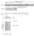
도5는 Normal 서브프레임 타입에서 PRB를 정의한 도면.
도6a 및 도6b는 백홀 서브프레임에서 FDM+TDM 방식 및 FDM 방식을 도시한 도면.
도7은 본 발명의 실시예에 따라 채널 자원 할당 과정을 도시한 도면.1 illustrates the configuration of an exemplary relay system in which the present invention may be practiced.
2 illustrates an LTE DL frame structure.
3 illustrates an LTE UL frame structure.
4 illustrates the structure of a backhaul subframe for SI avoidance in a relay system;
5 is a diagram illustrating a PRB in a normal subframe type.
6A and 6B illustrate an FDM + TDM scheme and an FDM scheme in a backhaul subframe.
7 is a diagram illustrating a channel resource allocation process according to an embodiment of the present invention.
이하 첨부된 도면을 참조하여 본 발명의 실시예들에 대해 상세히 설명한다. 다만, 이하의 설명에서는 본 발명의 요지를 불필요하게 흐릴 우려가 있는 경우, 널리 알려진 기능이나 구성에 관한 구체적 설명은 생략하기로 한다. Hereinafter, embodiments of the present invention will be described in detail with reference to the accompanying drawings. In the following description, well-known functions or constructions will not be described in detail if they obscure the subject matter of the present invention.
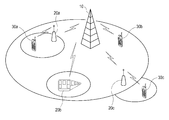
도1은 본 발명이 실시될 수 있는 예시적인 릴레이 시스템의 구성을 도시한 도면이다. 1 is a diagram illustrating a configuration of an exemplary relay system in which the present invention may be implemented.
도1에 도시된 바와 같이, 릴레이 시스템은 기지국(eNB)(10), 릴레이(RN)(20), 단말(UE)(30)로 구성된다.As shown in FIG. 1, the relay system includes a base station (eNB) 10, a relay (RN) 20, and a terminal (UE) 30.
기지국(10)은 해당 기지국(10)이 네트워크 접속 서비스를 제공하는 커버리지 영역(coverage region) 또는 셀 내의 릴레이(20) 및 단말(30)에 대해 무선 링크를 통한 통신 서비스를 제공할 수 있다. The
릴레이(20)는 중계기(repeater)를 대체하는 구성이 가능하며, 기지국(10)과 릴레이(20) 간 링크(backhaul link)에 사용되는 주파수밴드A가 릴레이(20)와 단말(30) 간 링크(access link)에 사용되는 주파수밴드B와 동일한 대역(inband)을 사용할 수 있다. 즉 릴레이(20)는 주파수밴드A와 주파수밴드B가 같고 송수신 구간을 시간상으로 분리하여 적용하는 inband half-duplex relay일 수 있다. 또한 릴레이(20)는 주파수밴드A와 주파수밴드B가 다른 아웃밴드(outband) 릴레이일 수 있다. The
릴레이(20)는 기지국(10)과 통신하기 위한 도너 안테나(donor antenna)와 단말(30)과 통신하기 위한 서비스 안테나(service antenna)를 구비하며, 이를 통해 기지국(10)과 단말(30) 간에 통신 중재 역할을 수행한다. 릴레이(20)는 백홀 링크(backhaul link)에 있어 유선이 아닌 무선 백홀을 이용하므로 새로운 기지국의 추가나 유선 백홀의 설치가 필요없는 장점이 있다. The
릴레이(20)는 하향링크(downlink)(/상향링크(uplink))시 기지국(10)(/단말(30))으로부터 미리 약속된 시간과 주파수에서 신호를 전송받아, 수신한 신호에서 DL/UL SI 성분을 제거한 후 다시 전송 구조에 맞게 변조하여 단말(30)(/기지국(10))로 재전송을 수행한다. The
릴레이(20)는 무선 백홀(wireless backhaul)을 통해 기지국(10) 커버리지 내의 임의의 장소에 위치하여 단말(Macro UE)에 대해서는 기지국(eNB)처럼 인식되며, 반면에 기지국(10)에 대해서는 하나의 단말(Macro UE) 처럼 인식되어, 기지국(10)과 단말(30a~30c) 사이에서 신호를 중계하여 통신 커버리지 영역을 확장시킬 수 있다. The
일반적으로 기지국(10)은 위치가 고정되어 있으므로 이동통신망 구성에 있어서 유연성이 낮으며, 따라서 트래픽 분포나 통화 요구량 변화가 심한 무선 환경에서는 효율적인 통신 서비스를 제공하기 어렵다. 이와 같은 단점을 극복하기 위해, 릴레이 시스템은 한 지점에 고정적으로 위치하는 고정 릴레이(fixed RN)(20a,20c)나, 기차나 대형버스 등에 장착되어 이동성을 갖는 이동 릴레이(mobile RN)(20b)를 사용하여 멀티홉 방식으로 이동통신망을 구성함으로써 릴레이 시스템의 통신 서비스 영역을 확장시키고 시스템 용량을 증대시킬 수 있다. 또한 릴레이(20)는 이벤트성의 가입자 폭주를 지원하기 위해 차량에 장착되는 Nomadic RN일 수 있다. In general, since the
도시된 바와 같이, 기지국(10)은 기지국(10)의 통신 커버리지 영역에 포함되는 단말(30a,30b)에 대하여 직접 또는 릴레이(20a)를 통해 데이터를 전송하고, 기지국(10)의 통신 커버리지 영역 밖에 위치하여 직접 통신할 수 없는 단말(30c)에 대해서는 릴레이(20c)를 통해 데이터를 전송한다. 또한, 기지국(10)의 통신 커버리지 영역 밖에 위치하는 단말(30c)은 전송 파워의 제약으로 기지국(10)과 직접 통신을 할 수 없으므로 릴레이(20c)를 통해 데이터를 기지국(10)으로 전송한다. As shown, the
단말(30a~30c)은 예를 들어 핸드폰, 이동통신 기능을 가지는 휴대용 컴퓨터, 이동통신 기능을 가지는 PDA 또는 다른 기기를 포함하는 임의의 유형의 휴대용 무선통신기기 또는 시스템을 포함할 수 있다. 비록 도 1에서는 하나의 기지국(10)이 세 개의 릴레이(20a~20c)와 세 개의 단말(30a~30c)만을 지원하는 것으로 도시하고 있지만, 기지국(10)은 더 많거나 더 적은 수의 릴레이 및 단말을 지원할 수 있음에 유의하여야 한다.
구체적으로 도시되지는 않았으나, 릴레이(20a~20c) 또는 단말(30a~30c)은 기지국(10)으로 상향링크 채널을 통해 신호를 전송하고, 기지국(10)은 릴레이(20a~20c) 또는 단말(30a~30c)로 하향링크 채널을 통해 신호를 전송한다. 특히 기지국(10)으로부터 릴레이(20a~20c)를 통하여 전송되는 정보를 포함하는 하향링크 채널의 서브프레임은 릴레이(20a~20c)를 위한 제어 정보의 전송을 위한 제어 채널(control channel) 및 데이터의 전송을 위한 데이터 채널(data channel)과, 단말(30a~30c)을 위한 제어 정보의 전송을 위한 제어 채널 및 데이터의 전송을 위한 데이터 채널을 포함하도록 구성된다. 릴레이(20a~20c) 및 단말(30a~30c)을 위한 각 제어 채널은 시간축 상에서 나머지 데이터 채널에 앞서 위치한다. 이는 릴레이(20a~20c) 및 단말(30a~30c)이 우선적으로 제어 채널을 수신하여 자신에게 전송되는 데이터 채널의 전송 여부를 인지함으로써 데이터 채널 수신 동작을 수행할 것인가를 판단하도록 하기 위함이다. 따라서, 각 릴레이(20a~20c) 및 단말(30a~30c)은 제어 채널로부터 자신에게 전송되는 데이터 채널이 없다고 판단할 경우 이후의 데이터 채널을 수신할 필요가 없으므로 데이터 채널의 수신에서 소모되는 전력을 아낄 수 있다. Although not specifically illustrated, the
OFDMA 방식을 사용하는 LTE(Long Term Evolution) 시스템을 기반으로 릴레이(20a~20c)를 설명하면 다음과 같다. The
3GPP LTE 시스템은 다중 대역폭(multiple bandwidth)에 대하여 정의하고 있는데, 이는 다음의 표1과 같다.The 3GPP LTE system defines multiple bandwidths, which are shown in Table 1 below.

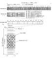
LTE는 OFDMA 방식을 사용하는 이동통신 시스템으로, 전송 프레임 구조는 도2 및 도3과 같다. 도2는 10MHz의 전송 대역폭을 갖는 LTE DL(DownLink) 프레임 구조이고, 도3은 10MHz의 전송 대역폭을 갖는 LTE UL(UpLink) 프레임 구조이다.LTE is a mobile communication system using the OFDMA scheme, and the transmission frame structure is shown in FIGS. 2 and 3. FIG. 2 is an LTE DL (DownLink) frame structure having a transmission bandwidth of 10 MHz, and FIG. 3 is an LTE UL (UpLink) frame structure having a transmission bandwidth of 10 MHz.
도2를 참조하면, 서브프레임의 가로 방향은 시간 축을 나타내고 세로 방향은 주파수 축을 나타낸다. 서브프레임은 시간 축을 따라 소정 수의 심볼을 포함하며, 주파수 축을 따라 소정의 대역폭에 걸쳐 있다. 서브프레임 내의 각 영역은 시간과 주파수 영역에서 정해지는 무선 자원을 나타낸다. Referring to FIG. 2, the horizontal direction of the subframe represents the time axis and the vertical direction represents the frequency axis. The subframe includes a predetermined number of symbols along the time axis and spans a predetermined bandwidth along the frequency axis. Each region in the subframe represents a radio resource determined in the time and frequency domain.
LTE DL 프레임 구조에서 최소 전송 단위는 TTI(Transmission Time Interval)이다. 각각의 TTI(subframe)는 2개의 연속된 슬롯(짝수번째 슬롯(even-numbered slot)과 홀수번째 슬롯(odd-numbered slot)이 1TTI, 즉 한 쌍의 PRB(Physical Resource Block)를 구성함)으로 이루어진다. 하나의 슬롯은 50개의 RB(Resource Block)로 이루어진다. 예컨대 하나의 RB는 시간축 7심볼(l=0,...6)과 주파수축 12서브캐리어(subcarrier)로 이루어진다. 이 경우 각 RB는 84개(7x12=84개)의 RE(Resource Element)로 이루어진다. 기지국(eNB)에서 단말(UE)로의 DL 데이터 전송은 RB 단위로 이루어진다. LTE DL 프레임 구조에서 DL 데이터의 전송은 PDSCH(Physical Downlink Shared Channel)를 통해 이루어지고, DL 제어 정보 전송은 PDCCH(Physical Downlink Control Channel), PCFICH(Physical Control Format Indicator Channel), PHICH(Physical Hybrid ARQ Indicator Channel)를 통해 이루어진다. DL 동기 채널로는 P-SCH(Primary Synchronization Channel), S-SCH(Secondary Synchronization Channel)가 있다. 또한 DL 데이터 및 DL 제어 정보의 코히어런트(coherent) 검출(detection) 및 측정(measurement)을 위한 신호로 RS(Reference Signal)를 사용한다. The minimum transmission unit in the LTE DL frame structure is a transmission time interval (TTI). Each TTI (subframe) is composed of two consecutive slots (even-numbered slots and odd-numbered slots constitute 1TTI, that is, a pair of Physical Resource Blocks (PRBs)). Is done. One slot consists of 50 resource blocks (RBs). For example, one RB consists of a time axis of 7 symbols (l = 0, ... 6) and a frequency axis of 12 subcarriers. In this case, each RB consists of 84 resource elements (7x12 = 84). DL data transmission from the eNB to the UE is performed in units of RBs. In the LTE DL frame structure, DL data is transmitted through a physical downlink shared channel (PDSCH), and DL control information is transmitted through a physical downlink control channel (PDCCH), a physical control format indicator channel (PCFICH), and a physical hybrid ARQ indicator (PHICH). Channel). DL synchronization channels include a Primary Synchronization Channel (P-SCH) and a Secondary Synchronization Channel (S-SCH). In addition, RS is used as a signal for coherent detection and measurement of DL data and DL control information.
PCFICH는 제어 포맷 지시(CFI: Control Format Indicator) 정보를 전송하기 위한 물리 채널이다. CFI란 해당 서브프레임 내에서 PDCCH가 위치하는 OFDM 심볼의 수를 나타내는 2비트 길이의 정보이다. UE는 우선적으로 CFI를 수신하여야 비로서 PDCCH의 OFDM 심볼의 수를 파악할 수 있다. 따라서, 서브프레임을 수신한 UE가 PCFICH를 해당 서브프레임 중 최초로 수신할 수 있도록 PCFICH는 해당 서브프레임의 첫 번째 OFDM 심볼 위치에 배치된다. PCFICH는 주파수 측면에서 분할된 복수의 영역에 걸쳐 위치하며 이로써 주파수 다이버시티에 의한 이득을 얻을 수 있다.PCFICH is a physical channel for transmitting control format indicator (CFI) information. CFI is 2-bit length information indicating the number of OFDM symbols in which a PDCCH is located in a corresponding subframe. The UE must first receive the CFI to determine the number of OFDM symbols of the PDCCH as a ratio. Accordingly, the PCFICH is located at the first OFDM symbol position of the subframe so that the UE receiving the subframe can receive the PCFICH first of the subframes. The PCFICH is located over a plurality of divided regions in terms of frequency, thereby obtaining a gain due to frequency diversity.
PDCCH는 이후 수신될 데이터 채널의 할당에 관한 정보 혹은 전력 제어에 관한 정보 등을 송신하는 제어 채널이다. PDCCH를 위한 변조 방식으로는 통상적으로 QPSK가 사용되는데, UE의 채널 상태에 따라 채널 부호화율을 변경하는 경우 PDCCH를 위하여 사용되는 자원의 양이 변경될 수 있다. 따라서 채널 상태가 양호한 UE에 대해서는 높은 채널 부호화율을 적용하여 사용되는 자원의 양을 감소시킬 수 있다. 반면에 채널 상태가 불량한 UE에 대해서는 사용되는 자원의 양을 늘리더라도 낮은 채널 부호화율을 적용하여 수신 정확도를 높일 수 있다. The PDCCH is a control channel for transmitting information on allocation of a data channel to be received or information on power control. QPSK is commonly used as a modulation scheme for the PDCCH. When the channel coding rate is changed according to the channel state of the UE, the amount of resources used for the PDCCH may be changed. Therefore, a high channel coding rate may be applied to a UE having a good channel state to reduce the amount of resources used. On the other hand, even if the amount of resources used is increased for a UE having a poor channel state, the reception accuracy can be improved by applying a low channel coding rate.
PDSCH는 UE로 전달되는 데이터를 송신하는 데이터 채널이다. PDSCH is a data channel for transmitting data delivered to a UE.
도면에는 도시되지 않았지만, 하향링크 채널의 서브프레임은 또한 eNB 내의 RN을 위한 제어 정보에 관한 채널인 R-PCFICH(Relay node Physical Control Format Indicator Channel) 및 R-PDCCH(Relay node Physical Downlink Control Channel)와 RN을 위한 데이터에 관한 채널인 R-PDSCH(Relay node Physical Downlink Shared Channel)를 포함한다. R-PDCCH, R-PDSCH 및 R-PDSCH는 각각 RN을 위한 정보라는 점에서만 다를 뿐, 그 기능과 역할은 UE와 관련하여 전술한 PCFICH, PDCCH 및 PDSCH와 유사하다. Although not shown in the figure, the subframes of the downlink channel may also include a relay node physical control format indicator channel (R-PCFICH) and a relay node physical downlink control channel (R-PDCCH), which are channels for control information for the RN in the eNB. It includes a relay node Physical Downlink Shared Channel (R-PDSCH), which is a channel for data for RN. R-PDCCH, R-PDSCH, and R-PDSCH are different only in that they are information for RN, respectively, and their functions and roles are similar to those of PCFICH, PDCCH, and PDSCH described above with respect to UE.
R-PCFICH는 R-CFI(Relay Control Format Indicator) 정보를 전송하기 위한 물리 채널이다. R-CFI란 eNB 내의 RN을 위한 제어 채널인 R-PDCCH가 사용하는 OFDM 심볼의 수를 지시하는 정보이다. R-CFI의 정확한 전송은 이동통신 시스템의 안정성을 확보하는데 있어서 매우 중요하기 때문에, 전송 과정에서 오류가 발생하는 것을 최소화하기 위해 매우 낮은 코딩률을 가지는 코드를 이용하여 전송될 것이 요구된다. The R-PCFICH is a physical channel for transmitting relay control format indicator (R-CFI) information. R-CFI is information indicating the number of OFDM symbols used by the R-PDCCH, which is a control channel for an RN in an eNB. Since the accurate transmission of the R-CFI is very important in securing the stability of the mobile communication system, it is required to be transmitted using a code having a very low coding rate in order to minimize an error in the transmission process.
R-PDCCH는 RN을 위한 데이터 채널의 할당에 관한 정보 혹은 전력 제어에 관한 정보 등을 송신하는 제어 채널이다. The R-PDCCH is a control channel for transmitting information on allocation of a data channel for RN or information on power control.
R-PDSCH는 RN으로 전달되는 데이터를 송신하는 데이터 채널이다. R-PDSCH is a data channel for transmitting data delivered to the RN.
한편 이해를 돕기 위하여 도3을 참조하면, LTE UL 프레임 구조에서 TTI, Slot, RB, RE에 대한 정의는 LTE DL 프레임 구조에서와 동일하다. LTE UL 프레임 구조에서 UL 데이터의 전송은 PUSCH(Physical Uplink Shared Channel)를 통해 이루어지고, UL 제어 정보는 PUCCH(Physical Uplink Control Channel)를 통해 이루어진다. UL 채널 측정을 위하여 SRS(Sounding Reference Signal)가 사용되는데, SRS 전송 위치는 TTI에서 2번째 슬롯(홀수번째 슬롯(odd-numbered slot))의 마지막 심볼(l=6)에 위치할 수 있다(미도시됨). 또한 UL 데이터 및 UL 제어 정보의 코히어런트 검출 및 측정을 위한 신호로 RS를 사용한다. Meanwhile, referring to FIG. 3 for better understanding, the definition of TTI, Slot, RB, and RE in the LTE UL frame structure is the same as in the LTE DL frame structure. In the LTE UL frame structure, UL data is transmitted through a PUSCH (Physical Uplink Shared Channel), and UL control information is performed through a PUCCH (Physical Uplink Control Channel). The SRS (Sounding Reference Signal) is used for UL channel measurement, and the SRS transmission position may be located at the last symbol (l = 6) of the second slot (odd-numbered slot) in the TTI. Shown). In addition, RS is used as a signal for coherent detection and measurement of UL data and UL control information.
LTE Release 8에서 상향링크(UE에서 eNB로)로 전송되는 물리계층 신호는 PUCCH, PUSCH, SRS 등이 있다. PUCCH는 상향링크 제어신호를 전송하기 위한 물리계층의 채널로서, 이 채널을 통하여 상향링크 스케줄링 요청 정보(SR), 하향링크 데이터 전송에 따른 응답 정보(HARQ ACK/NACK) 및 채널품질정보(CQI/PMI/RI) 등이 전송된다. PUSCH는 주로 UE의 데이터를 전송하기 위한 물리채널로서, 하나의 UE가 데이터 및 제어신호를 동시에 보낼 필요가 있을 경우에 이 채널을 통하여 다중화되어 전송된다. SRS는 eNB에서 상향링크의 채널품질을 측정하거나 eNB와 UE 간의 시간 동기를 맞추기 위한 타이밍 정보 측정에 사용된다. Physical layer signals transmitted from uplink (UE to eNB) in LTE Release 8 include PUCCH, PUSCH, and SRS. PUCCH is a channel of a physical layer for transmitting an uplink control signal, and through this channel, uplink scheduling request information (SR), response information according to downlink data transmission (HARQ ACK / NACK), and channel quality information (CQI / PMI / RI) and the like are transmitted. PUSCH is mainly a physical channel for transmitting data of a UE, and when one UE needs to simultaneously transmit data and control signals, it is multiplexed and transmitted through this channel. The SRS is used for measuring timing information for measuring channel quality of uplink at the eNB or time synchronization between the eNB and the UE.
eNB와 RN 간의 무선 백홀 인터페이스를 "Un 인터페이스(backhaul link)"라 하고, RN과 RN 셀 내 UE 간의 액세스 인터페이스를 "Uu 인터페이스(access link)"라 한다. 또한 일반적인 무선 중계기처럼 백홀 상에 존재하는 SI(Self Interference)를 방지하기 위해 Un 인터페이스상에서 RN은 eNB로부터의 데이터 수신과 UE에 대한 데이터 전송을 위한 시간을 구분하여 수행하기 위해 도4와 같이 백홀 타이밍(backhaul timing)에 MBSFN(MBMS Single Frequency Network) 서브프레임을 사용하여 MBSFN 서브프레임의 데이터부(data part)를 eNB로부터의 백홀 데이터(backhaul data) 수신을 위해 사용하며, 이때 Legacy UE의 CQI measurement 오류를 피하기 위해 첫 번째와 두 번째 심볼이 위치한 제어부(control part)에 안테나 포트별 Cell Specific Reference Signal(R0: ANT Port 0, R1: ANT Port 1, R2: ANT Port 2, R3: ANT Port 3)를 엑세스 구간으로 전송한다. 추가적으로 RN에서 백홀 데이터 수신과 엑세스 링크(access link) 상에 데이터 전송을 위한 processing switching을 이들 사이에 1ms 이하 보호 구간(guard period)을 두어 데이터 송신과 수신 사이에 스위칭을 수행한다. 또한 현재 3GPP에서 DL 백홀 서브프레임의 효과적인 사용을 위해 백홀 서브프레임 타이밍마다 UE와 RN을 위한 DL 데이터와 제어를 동시에 지원하는 FDM + TDM 방식 및 FDM 방식을 고려하고 있다.The wireless backhaul interface between the eNB and the RN is referred to as an "un interface (backhaul link)", and the access interface between the RN and the UE in the RN cell is referred to as an "access link". Also, in order to prevent self interference (SI) existing on the backhaul like a general wireless repeater, the RN on the Un interface performs a backhaul timing as shown in FIG. 4 to separate the time for data reception from the eNB and data transmission to the UE. MBSFN (MBMSN Single Frequency Network) subframe is used for backhaul timing to receive backhaul data from eNB, which is the CQI measurement error of Legacy UE. In order to avoid the problem, the cell specific reference signals (R0:
3GPP에서 논의되고 있는 백홀 링크에 사용될 수 있는 서브프레임 타입은 두 가지로 정의하고 있다. eNB가 MBMS 서비스를 지원하지 않는 경우에는 'Normal 서브프레임'을, MBMS 서비스를 지원하는 경우에는 'MBSFN 서브프레임'을 백홀 링크에 사용한다. Two types of subframes that can be used for the backhaul link discussed in 3GPP are defined. When the eNB does not support the MBMS service, the 'Normal subframe' is used, and when the eNB supports the MBMS service, the 'MBSFN subframe' is used for the backhaul link.
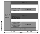
한편 R-PDCCH에 대한 다중화 방안은 크게 두 가지로 제안되고 있다, 즉 도6a와 같이 PDSCH와 RN 데이터가 FDM(Frequency Division Multiplexing)으로 다중화됨과 동시에 R-PDCCH와 R-PDSCH가 TDM(Time Division Multiplexing) 방식으로 다중화되는 "FDM+TDM 방식"과, 도6b와 같이 FDM+TDM과는 달리 R-PDCCH와 R-PDSCH 사이에 TDM 없이 FDM만을 사용하는 "FDM 방식"으로 구분된다.On the other hand, two schemes for multiplexing the R-PDCCH have been proposed. That is, as shown in FIG. 6A, PDSCH and RN data are multiplexed by frequency division multiplexing (FDM) and R-PDCCH and R-PDSCH are TDM (Time Division Multiplexing). 6F is divided into " FDM + TDM scheme " and " FDM scheme " using only FDM without TDM between R-PDCCH and R-PDSCH, unlike FDM + TDM as shown in FIG. 6B.
도6b에 도시된 바와 같이, FDM 방식에서는 시간 영역(time domain)에서 R-PDCCH와 R-PDSCH가 동일하게 4번째부터 13번째 심볼까지를 차지하며, R-PDCCH와 R-PDSCH가 주파수 영역(frequency domain)에서 다중화된다. 즉 eNB는 상위계층(higher layer)을 통해 R-PDCCH로 사용될 수 있는 PRB set을 semi-statistic하게 설정하여 모든 RN에게 R-PDSCH를 통해 전송하며, 변경이 요구되면 개별 RN에게 R-PDSCH를 통해 각각 전송한다. DMRS(Demodulation Reference Signal)를 통한 R-PDCCH의 프리코딩(pre-coding) 적용이 용이하게 되나, 도5에서처럼 CRS가 위치하는 심볼에서는 2개의 REGs가, CRS가 위치하지 않는 심볼에서는 3개의 REGs 존재하게 되어 총 29개의 REGs가 한 쌍의 PRB 내에 존재하게 된다. 따라서 legacy의 경우 One PDCCH를 위한 최소 CCE 크기가 9REGs로 구성되는 것에 비교하면 R-PDCCH에 대한 인터리빙 및 RE mapping rule의 새로운 정의가 요구될 것이며, FDM+TDM 보다 커진 single R-PDCCH의 크기로 인해 자원 낭비를 유발할 수 있다. 또한 FDM의 특성상 frequency selectivity scheduling의 지원은 용이하나, 새로운 RN 도입 및 해제시 뿐만 아니라 개별 RN에 대한 best frequency 변경시에도 semi-statistic하게 R-PDCCH를 재설정과 이를 위한 재신호가 요구되며, 또한 Macro UE 를 위한 frequency selectivity scheduling과 충돌을 유발할 수 있다. 만약 RN의 R-PDCCH에 대한 blind detection overhead를 감소하기 위해 RN별 PRB region을 정의한 경우는 RN의 위치변경시마다 재설정이 요구되거나 주파수 다이버시티 효과의 저하를 유발할 수 있을 것이며, 반면에 주파수 다이버시티 효과 증대를 위해 한 쌍의 PRB 내에 다수의 RN에 대한 R-PDCCH를 맵핑하는 경우에는 blind detection overhead를 증가시킬 수 있을 것이다. As shown in FIG. 6B, in the FDM scheme, the R-PDCCH and the R-PDSCH occupy the fourth to thirteenth symbols in the same time domain, and the R-PDCCH and the R-PDSCH correspond to the frequency domain. multiplexed in the frequency domain). That is, the eNB semi-statistically sets a PRB set that can be used as an R-PDCCH through a higher layer and transmits it to all RNs through an R-PDSCH, and when a change is required, an R-PDSCH to an individual RN. Transmit each. It is easy to apply pre-coding of R-PDCCH through DMRS (Demodulation Reference Signal), but there are two REGs in the symbol where CRS is located and three REGs in the symbol where CRS is not located, as shown in FIG. As a result, a total of 29 REGs exist in a pair of PRBs. Therefore, in case of legacy, the minimum CCE size for One PDCCH is composed of 9REGs, and the new definition of interleaving and RE mapping rule for R-PDCCH will be required, due to the size of single R-PDCCH larger than FDM + TDM. It can be a waste of resources. In addition, it is easy to support frequency selectivity scheduling due to the nature of FDM, but it is required to reset R-PDCCH semi-statistically and re-signal for not only the introduction and release of new RN but also the best frequency change for individual RN. May cause collisions with frequency selectivity scheduling for the UE. If the RN PRB region is defined to reduce the blind detection overhead of the RN's R-PDCCH, resetting may be required for each change of the RN's position, or the frequency diversity effect may be degraded. In order to increase R-PDCCH for a plurality of RNs in a pair of PRBs, blind detection overhead may be increased.
도6a에 도시된 바와 같이, FDM+TDM의 경우 시간 영역에서 4번째부터 7번째 심볼까지를 R-PDCCH의 영역으로 정의하며, 주파수 영역에서 R-PDCCH에 대한 자원 할당은 FDM과 동일하다. 한 쌍의 PRB에서 semi-statistic하게 설정된 R-PDCCH에 연속된 2번째 슬롯을 Normal R-PDSCH로 정의하며, R-PDSCH를 위한 자원이 부족한 경우에 한 쌍의 PRB의 4번째 심볼부터 13번째 심볼까지를 사용하는 Extend R-PDSCH로 정의하고 있다. 물론 2가지 타입 할당시 별도의 식별자는 사전에 R-PDCCH를 위해 할당된 PRB set을 모든 RN이 인지하고 있기에 요구되지 않는다. 만약 semi-statistic하게 할당된 R-PDCCH가 사용되지 않는 경우에는 한 쌍의 PRB 전체가 PDSCH를 위해 할당되며, CCE 크기를 11 REG로 정의하여 One PRB 내에서만 인터리빙을 수행한다. aggregation level에 따라 동일한 R-PDCCH가 semi-statistic하게 설정된 다른 PRB 영역에 중복된다. 또한 새로운 RN 도입 및 해제시에는 주파수 영역에서 semi-statistic하게 R-PDCCH를 위한 PRB를 상위계층에서 재설정 및 재신호하여야 한다. As shown in FIG. 6A, in the case of FDM + TDM, the fourth to seventh symbols in the time domain are defined as the regions of the R-PDCCH, and the resource allocation for the R-PDCCH in the frequency domain is the same as that of the FDM. In a pair of PRBs, a second slot consecutively formed in a semi-statistically-configured R-PDCCH is defined as a normal R-PDSCH.In case of insufficient resources for the R-PDSCH, the fourth to 13th symbols of the pair of PRBs are insufficient. It is defined as Extend R-PDSCH using. Of course, when assigning two types, a separate identifier is not required because all RNs recognize the PRB set previously allocated for the R-PDCCH. If semi-statistically allocated R-PDCCH is not used, the entire pair of PRBs are allocated for the PDSCH, and the interleaving is performed only in one PRB by defining the CCE size as 11 REG. The same R-PDCCH is duplicated in another PRB region semi-statistically set according to the aggregation level. In addition, when introducing and releasing a new RN, the PRB for the R-PDCCH needs to be reset and re-signaled in the upper layer semi-statistically in the frequency domain.
상기 두 가지 방식 모두 R-PDCCH blind detection을 위한 효과적인 새로운 rule이 정의되어야 할 것이다. 특히 본 발명에서는 FDM+TDM에서 full frequency diversity 및 효과적인 R-PDCCH에 대한 blind detection 및 R-PDCCH 영역의 크기에 대한 동적 할당과 R-PDCCH 영역에 대한 정보의 효과적인 전달을 위한 방안에 그 핵심을 두고 있다. In both methods, an effective new rule for R-PDCCH blind detection should be defined. Particularly, the present invention focuses on the method for full frequency diversity and effective detection of blind detection for the effective R-PDCCH, dynamic allocation of the size of the R-PDCCH region and effective transmission of information on the R-PDCCH region in FDM + TDM. have.
FDM+TDM에서 eNB는 semi-statistic하게 R-PDCCH의 영역을 모든 RN에게 통보해야 하며, 변경이 필요한 경우에 재통보해야 한다. 따라서 재통보를 위한 오버헤드를 줄이기 위해서는 최초부터 충분한 R-PDCCH 할당을 통해 새로운 RN시 재설정과 재통보를 피해야 하며, 이 경우 커진 R-PDCCH에 대한 PRB set으로 인해 RN의 R-PDCCH에 대한 blind detection 횟수를 증가시킬 것이다. 즉 이러한 경우에는 donor cell의 RN이 모두 고정적이며 채널 환경의 변경이 거의 발생치 않는다는 가정하에서는 어느 정도의 R-PDCCH를 위한 PRB set 재설정을 피할 수는 있을 것이나, Mobile/Nomadic RN을 가정한다면 PRB set 재설정을 위해 R-PDSCH 자원에 대한 심각한 낭비를 유발할 수 있을 것이다. 또한 인터리빙의 경우 하나의 PRB 이내에서만 인터리빙되어야 하므로 인터리빙 효과가 저하되며, R-PDCCH의 CCE 크기가 One PRB 에 포함된 11 REGs로 정의되지 않는 경우 인터리빙 크기 문제로 인해 RN의 R-PDCCH에 대한 blind decoding overhead를 유발할 수 있다. 또한 aggregation level이 적은 R-PDCCH의 경우 One PRB에만 맵핑되므로 주파수 다이버시티 효과의 감소가 예상되며, UL R-PDSCH에 대한 hybrid ACK/NACK를 위한 R-PHICH를 포함하는 것이 용이치 않을 것이다. 이를 위해 R-PHICH 대신 UL grant를 위한 R-PDCCH를 통한 Nack의 전송을 사용할 수 있다. 그러나 이러한 경우 Mobile RN 및 backhaul CQI가 불안정한 경우에 UL R-PDSCH에 대한 NACK가 빈번히 발생할 것이며, 이를 feedback하기 위해 불필요한 R-PDCCH를 신호함으로써 R-PDCCH의 자원 소모가 예상된다. In FDM + TDM, the eNB must inform all RNs of the R-PDCCH region semi-statistically and re-notify when a change is necessary. Therefore, in order to reduce overhead for re-notification, it is necessary to avoid resetting and re-notification at the time of new RN through sufficient R-PDCCH allocation from the beginning. will increase the number of detections. In this case, it is possible to avoid resetting the PRB set for some R-PDCCH under the assumption that all the RNs of the donor cell are fixed and the channel environment hardly changes.However, if the mobile / Nomadic RN is assumed, the PRB set can be avoided. May cause significant waste of R-PDSCH resources for reconfiguration. In addition, in the case of interleaving, the interleaving effect is deteriorated because it must be interleaved only within one PRB. When the CCE size of the R-PDCCH is not defined as 11 REGs included in the One PRB, the interleaving blinds the R-PDCCH of the RN due to the interleaving size problem. May cause decoding overhead. In addition, since the R-PDCCH having a low aggregation level is only mapped to the One PRB, it is expected to reduce the frequency diversity effect, and it may not be easy to include the R-PHICH for hybrid ACK / NACK for the UL R-PDSCH. To this end, instead of R-PHICH, transmission of Nack through R-PDCCH for UL grant may be used. However, in this case, when the Mobile RN and the backhaul CQI are unstable, NACK for the UL R-PDSCH will frequently occur, and resource consumption of the R-PDCCH is expected by signaling an unnecessary R-PDCCH for feedback.
도7은 본 발명의 실시예에 따라 채널 자원 할당 과정을 도시한 도면으로서, PHICH 기반의 multi R-PDCCH region 할당 과정을 보여준다. FIG. 7 is a diagram illustrating a channel resource allocation process according to an embodiment of the present invention and shows a PHICH-based multi R-PDCCH region allocation process.
본 발명에 따른 eNB의 채널 자원 할당 장치는, RN 제어채널(R-PDCCH)에 대한 전송 단위 자원(PRB) 영역을 주파수 영역에서 복수 개(예컨대 3개)로 구분하고, 각 영역의 PRB 정보를 공통 RN 제어채널(Common R-PDCCH)을 통해 전송한다. 이때 각 R-PDCCH에 대한 3개의 영역은, PHICH에 기반한다. An apparatus for allocating channel resources of an eNB according to the present invention divides a transmission unit resource (PRB) region for an RN control channel (R-PDCCH) into a plurality (eg, three) in a frequency domain, and divides PRB information of each region. Transmit through common RN control channel (Common R-PDCCH). At this time, three regions for each R-PDCCH are based on PHICH.
여기서 구분의 일예로, R-PDCCH에 대한 PRB 영역을 주파수 영역에서 PHICH를 기준으로 3개의 영역으로 구분할 수 있다. 이 경우 Common R-PDCCH는, 기지국 내의 모든 RN이 동시에 인지해야 하는 정보로서, 3 레그(REGs)를 사용할 수 있다. 또한 Common R-PDCCH는, 백홀 서브프레임에서 최초로 인지해야 하는 채널로서, 고정된 위치에서 시작되며 해당 위치에 대해 특별한 신호 없이 인지된다. Common R-PDCCH 내의 포함된 PRB 정보는, 매 백홀 서브프레임마다 변경 가능하다. As an example of the division, the PRB region for the R-PDCCH may be divided into three regions based on the PHICH in the frequency domain. In this case, the Common R-PDCCH may use three legs (REGs) as information that all RNs in the base station should simultaneously recognize. In addition, the common R-PDCCH is a channel to be recognized first in the backhaul subframe, and starts from a fixed position and is recognized without a special signal for the position. The PRB information included in the common R-PDCCH can be changed for every backhaul subframe.
상기 구분된 영역은 인터리빙시 논리적으로 연속된 하나의 영역으로 처리할 수 있다. The divided area may be treated as one logically continuous area during interleaving.
일실시예에 있어서, PRB 정보는 동적 R-PDCCH 크기 및 PRB set 정보를 포함한다. 다른 실시예에 있어서, R-PDCCH의 영역 각각에 대한 PRB 개수, R-PHICH 그룹 개수, 페이징 정보를 포함한다. In one embodiment, the PRB information includes dynamic R-PDCCH size and PRB set information. In another embodiment, the number of PRBs, number of R-PHICH groups, and paging information for each region of the R-PDCCH is included.
구체적으로 살펴보면, 도7에서 Legacy의 경우, 즉 eNB의 경우 해당하는 PHICH는 대역폭(bandwidth) 및 PCI에 의해 3개의 특정 PRB의 REG에 중복된다. 또한 PHICH 그룹 개수만큼 각각의 영역에서 추가의 REG를 소모한다. 따라서 RN은 eNB의 대역폭 및 PCI를 사전에 알 수 있으므로 이들의 해당 위치를 알 수 있다. 이에 기반하여 R-PDCCH에 대한 PRB 영역을 주파수 측면에서 PHICH를 위한 3개의 PRB를 기준으로 3개의 영역으로 구분하며, Common R-PDCCH를 통해 각 영역의 PRB 크기를 지시한다. 다만 3개의 영역은 R-PDCCH 인터리빙시 논리적으로 연속된 영역으로 인식하여 인터리빙을 수행하게 함으로써, full frequency diversity의 효과를 달성할 수 있으며, legacy scheme에서와 동일한 dedicated RN-RNTI 기반의 search space rule를 적용하여 R-PDCCH에 대한 효과적인 blind detection을 달성할 수 있다. In detail, in FIG. 7, in the case of legacy, that is, eNB, a corresponding PHICH is overlapped with REGs of three specific PRBs by bandwidth and PCI. Also, additional REGs are consumed in each region by the number of PHICH groups. Therefore, the RN can know the bandwidth and PCI of the eNB in advance so that they can know their location. Based on this, the PRB region for the R-PDCCH is divided into three regions based on the three PRBs for the PHICH in terms of frequency, and indicates the PRB size of each region through the Common R-PDCCH. However, the three regions can achieve the effect of full frequency diversity by performing interleaving by recognizing them as logically continuous regions during R-PDCCH interleaving, and using the same dedicated RN-RNTI based search space rule as in the legacy scheme. By applying this, effective blind detection for R-PDCCH can be achieved.
이를 통해 R-PDCCH를 위한 PRB set에 대한 명시적인 시그널링이 요구되지 않아, R-PDSCH의 활용도를 증대할 수 있다. 물론 별도의 Common R-PDCCH를 위한 자원의 소모 및 RN이 dedicated R-PDCCH에 대한 detection 이전에 Common R-PDCCH를 디코딩해야 한다는 조건이 따르지만, Common R-PDCCH를 위한 자원은 도7에서처럼 3 REGs를 사용하므로 R-PDSCH 사용의 경우에 비해 자원의 소모는 문제시되지 않으며, Common R-PDCCH에 대한 디코딩 또한 BPSK 기반의 단순 블록 코딩(block coding)이므로 지연(latency)면에서 무시될 수 있다. Common R-PDCCH는 하나의 donor하에 모든 RN이 동시에 인지해야 하는 정보를 전달하는 새로운 채널로서, 상위계층에 의한 semi-statistic R-PDCCH에 의한 오버헤드를 줄이기 위해 동적 R-PDCCH 크기 및 PRB set 정보를 전달할 수 있게 해준다. 즉 Common R-PDCCH내의 포함된 정보는 매 백홀 서브프레임마다 변경될 수 있으며, Common R-PDCCH는 모든 RN이 백홀 서브프레임에서 최초로 인지해야 하는 채널로서 항상 고정된 위치에서 시작되어야 하며 해당 위치에 대해 특별한 신호 없이 인지되어야 한다. 결국 R-PDCCH PRB set 크기 변경이 요구될 때, 개별적인 R-PDSCH을 통한 전달없이 동적으로 변경을 알릴 수 있다. 해당 채널은 PHICH 위치에 기반한다. 또한 3개의 분리된 R-PDCCH 영역을 논리적인 하나의 영역으로 처리함으로써 R-PDCCH의 CCE 크기에 대한 dependency 제거 및 full frequency diversity 획득과 RN의 blind detect 횟수 및 릴레이 제어 영역에 R-PHICH 수용이 용이하게 된다. 즉 R-PHICH는 5번째 심볼에 시작하며, legacy와는 달리 QPSK 변조를 사용한다. As a result, explicit signaling for the PRB set for the R-PDCCH is not required, thereby increasing the utilization of the R-PDSCH. Of course, the resource consumption for the separate Common R-PDCCH and the condition that the RN must decode the Common R-PDCCH before the detection of the dedicated R-PDCCH, but the resource for the Common R-PDCCH is 3 REGs as shown in FIG. As a result, resource consumption is not a problem as compared to the case of using R-PDSCH, and since decoding for the common R-PDCCH is also simple block coding based on BPSK, it can be ignored in terms of latency. Common R-PDCCH is a new channel that delivers information that all RNs should recognize simultaneously under one donor. Dynamic R-PDCCH size and PRB set information are reduced to reduce overhead caused by semi-statistic R-PDCCH by higher layer. Allows you to pass That is, the information included in the common R-PDCCH can be changed in every backhaul subframe, and the common R-PDCCH is a channel that all RNs should first recognize in the backhaul subframe and should always start at a fixed position. It should be recognized without special signal. As a result, when a change in the size of the R-PDCCH PRB set is required, the change can be notified dynamically without transmission through the individual R-PDSCH. The channel is based on the PHICH location. In addition, by processing three separate R-PDCCH regions as one logical region, it is easy to remove dependency on the CCE size of R-PDCCH, acquire full frequency diversity, accommodate the number of blind detects and relay control region of RN. Done. That is, R-PHICH starts at the fifth symbol and, unlike legacy, uses QPSK modulation.
DL 백홀 서브프레임은 페이징(paging)을 위한 서브프레임과 SIB(System Information Blocks)1 전송을 위한 서브프레임이 배제되어, eNB의 SIB 중 변경이 발생한 경우에 RN이 이를 인지할 수 있는 방안이 없다. 즉 legacy의 경우 SIB 변경이 페이징을 전송한 후 다음번 modification period에 SIB1의 value tag을 통해 변경된 SIB를 인지하며, 스케쥴링 정보에 기반하여 변경된 SIB를 reading하게 된다. 그러나 eNB는 DL 백홀 서브플레임이 페이징을 허용하지 않아 페이징 전송이 불가하며, 페이징을 받더라도 SIB1이 매핑되는 DL 서브프레임 #5을 수신할 수 없으므로 기존 방식의 SIB 변경 인지는 불가능하다. 따라서 변경된 내용을 dedicated R-PDSCH를 통해 개별 전송하거나, Common R-PDCCH에 페이징을 대신하는 정보를 통해 common search space 기반의 Common R-PDSCH 존재 여부를 지시하여 하나의 R-PDSCH로 모든 RN에게 신호할 수 있으며, common search space 적용 여부를 지시함으로써 RN 요구시에만 common과 dedicated search space를 통한 blind decoding을 수행하여 processing overhead를 감소시킬 수 있다. The DL backhaul subframe excludes a subframe for paging and a subframe for transmitting System Information Blocks (SIB) 1, so that there is no way for the RN to recognize when a change occurs in the SIB of the eNB. That is, in case of legacy, the SIB change transmits paging and recognizes the changed SIB through the value tag of SIB1 in the next modification period, and reads the changed SIB based on the scheduling information. However, the eNB cannot perform paging transmission because the DL backhaul subframe does not allow paging, and even if receiving the paging, the eNB cannot receive
Common R-PDCCH에 대해 보다 구체적으로 살펴보면 다음과 같다. A more detailed look at the Common R-PDCCH is as follows.
1. Common R-PDCCH의 정보 획득1. Obtain information of Common R-PDCCH
Common R-PDCCH는 3개의 R-PDCCH 영역 각각에 대한 PRB 개수, R-PHICH 그룹 개수, 페이징을 명시한다. P-PDCCH를 위해 전체 이용 가능 PRB 개수는 "100/3 = 33 PRB"를 각각의 영역에서 최대 이용가능하며, 이를 6비트로 표현 가능하다. 3개 영역의 크기는 동일하거나 1 PRB씩 차이가 난다. 따라서 이를 명시하기 위해 2비트의 extension이 추가되며, 하나의 eNB에서 수용가능 최대 RN은 30개 정도로 3GPP에서 고려되고 있다. 따라서 4개의 R-PHICH 그룹으로 가정하게 되면 "2bits(paging)+ 6bits(33PRB) + 2bits(sub region별 1PRB 차이 존재 여부) + 2bits(R-PHICH 그룹 개수) = 12bits"의 real data를 BPSK modulation 및 3 repetition을 수행하여 Common R-PDCCH 위치의 RE에 맵핑시킨다. 예를 들어 전체 특정 백홀 서브프레임에 R-PDCCH로서 100 PRB 소모가 예상되고 R-PHICH 그룹 4개, 페이징이 필요하다면 "11" + "100001" + "01" + "11"로 real data가 구성된다. 즉 3개의 영역 모두 33 PRB이며, 마지막 영역만 1 PRB 더 할당됨을 명시한다. Common R-PDCCH specifies the number of PRBs, the number of R-PHICH groups, and paging for each of three R-PDCCH regions. The total number of PRBs available for the P-PDCCH is "100/3 = 33 PRBs" available in each region at maximum, which can be expressed in 6 bits. The three areas are the same size or differ by 1 PRB. Therefore, to specify this, a 2-bit extension is added, and a maximum of 30 RNs that can be accommodated in one eNB is considered in 3GPP. Therefore, assuming 4 R-PHICH groups, BPSK modulation is performed on "2 bits (paging) + 6 bits (33 PRB) + 2 bits (1PRB difference per sub region) + 2 bits (number of R-PHICH groups) = 12 bits". And 3 repetition to map to the RE of the Common R-PDCCH location. For example, if 100 PRBs are expected to be consumed as R-PDCCH in all specific backhaul subframes and 4 R-PHICH groups and paging are required, real data consists of "11" + "100001" + "01" + "11". do. That is, it is specified that all three areas are 33 PRBs, and only the last area is allocated 1 PRB.
2bits(sub region별 1PRB 차이 존재 여부)에 대한 세부적으로 명시하면 R-PDCCH로서 9/10/11 PRB 예상시 해당 bits는 "00"/"01"/"11"로 명시된다. If the 2bits (1PRB difference exists per sub region) are specified in detail, the corresponding bits are designated as "00" / "01" / "11" when the 9/10/11 PRB is expected as an R-PDCCH.
2. Common R-PDCCH를 통한 각 영역별 PRB 개수 및 R-PHICH의 위치 검출2. Detection of PRB number and location of R-PHICH for each region through Common R-PDCCH
세 개의 영역 각각에 대한 PRB 개수를 인지하며, RN은 3개의 영역을 논리적으로 연속된 PRB 영역으로 인식하며, Common R-PDCCH를 위한 3 REGs 자체와 R-PHICH 그룹 개수를 통해 R-PHICH를 위한 REGs 및 CRS를 위한 REGs를 제외한 나머지 REGs로 CCE 크기에 기반한 CCE numbering을 수행하며, 자신의 Dedicated R-PDCCH를 인지하기 위해 RN-RNTI에 기반한 RN dedicated specific space에 의해 legacy UE 처럼 blind detection을 수행한다. Recognizing the number of PRBs for each of the three regions, the RN recognizes three regions as logically contiguous PRB regions, and the 3 REGs for the Common R-PDCCH itself and the number of R-PHICH groups through the number of R-PHICH groups. It performs CCE numbering based on CCE size with REGs except REGs and REGs for CRS, and performs blind detection like legacy UE by RN dedicated specific space based on RN-RNTI to recognize its dedicated R-PDCCH. .
만약 페이징이 지시되었다면 legacy에서와 비슷하게 최상위 CCE 0-2까지 fixed aggregation level 2로 non-blind decoding을 통해 Common R-PDCSH에 대한 channel coding 정보 및 PRB number를 인지하게 된다. If paging is indicated, the channel coding information and the PRB number for the Common R-PDCSH are recognized through non-blind decoding at fixed
3. R-PHICH 인지3. R-PHICH recognition
만약 이전 UL 백홀 서브프레임에 UL 백홀 데이터 전송에 의한 ACK/NACK를 기다린다면 legacy UE처럼 자신의 Group ID 및 UL grant와 자신의 R-PHICH를 위한 Orthogonal sequences를 기반으로 자신의 ACK/NACK를 검출(detection)한다 If waiting for ACK / NACK by UL backhaul data transmission in previous UL backhaul subframe, it detects its ACK / NACK based on its Group ID and UL grant and Orthogonal sequences for its R-PHICH like legacy UE. detection
4. Common R-PDCCH를 통한 각 영역별 PRB 개수 변경에 대한 인지 4. Acknowledgment of the change of the number of PRBs for each area through Common R-PDCCH
새로운 RN 도입 및 해제 또는 RN active UE에 의한 R-PDCCH를 위한 PRB 개수 변경시 eNB는 동적으로 매 DL 백홀 서브프레임마다 Common R-PDCCH의 content을 적절히 변경하여 신호 전송하며, 모든 RN은 항상 이를 인지할 수 있다. When introducing and releasing a new RN or changing the number of PRBs for the R-PDCCH by the RN active UE, the eNB dynamically signals the appropriate content of the Common R-PDCCH in every DL backhaul subframe, and all RNs always recognize this. can do.
5. Common R-PDCCH가 포함된 한 쌍의 PRB에 2슬롯이 R-PDSCH로 할당되지 않은 경우, 즉 R-PDCCH에 비해 R-PDSCH를 위한 요구자원이 적은 경우 REL-10 UE만을 해당 PRB에 할당하여 자원의 낭비를 줄일 수 있다. 또한 반대의 경우 R-PDSCH는 PDSCH 영역에 맵핑된다. 5. If 2 slots are not allocated to the R-PDSCH in a pair of PRBs including the Common R-PDCCH, that is, if the required resources for the R-PDSCH are smaller than those of the R-PDCCH, only the REL-10 UE is assigned to the PRB. By allocating resources to reduce waste. In the opposite case, the R-PDSCH is mapped to the PDSCH region.
상기 방법은 특정 실시예들을 통하여 설명되었지만, 상기 방법은 또한 컴퓨터로 읽을 수 있는 기록매체에 컴퓨터가 읽을 수 있는 코드로서 구현하는 것이 가능하다. 컴퓨터가 읽을 수 있는 기록매체는 컴퓨터 시스템에 의해 읽혀질 수 있는 데이터가 저장되는 모든 종류의 기록장치를 포함한다. 컴퓨터가 읽을 수 있는 기록매체의 예로는 ROM, RAM, CD-ROM, 자기 테이프, 플로피 디스크, 광데이터 저장장치 등이 있으며, 또한 케리어 웨이브(예를 들어 인터넷을 통한 전송)의 형태로 구현되는 것도 포함한다. 또한, 컴퓨터가 읽을 수 있는 기록매체는 네트워크로 연결된 컴퓨터 시스템에 분산되어, 분산방식으로 컴퓨터가 읽을 수 있는 코드가 저장되고 실행될 수 있다. 그리고, 상기 실시예들을 구현하기 위한 기능적인(functional) 프로그램, 코드 및 코드 세그먼트들은 본 발명이 속하는 기술분야의 프로그래머들에 의해 용이하게 추론될 수 있다.Although the method has been described through specific embodiments, the method may also be embodied as computer readable code on a computer readable recording medium. Computer-readable recording media include all kinds of recording devices that store data that can be read by a computer system. Examples of computer-readable recording media include ROM, RAM, CD-ROM, magnetic tape, floppy disks, optical data storage devices, and the like, which are also implemented in the form of carrier waves (for example, transmission over the Internet). Include. The computer readable recording medium can also be distributed over network coupled computer systems so that the computer readable code is stored and executed in a distributed fashion. In addition, functional programs, codes, and code segments for implementing the above embodiments can be easily deduced by programmers of the present invention.
본 명세서에서는 본 발명이 일부 실시예들과 관련하여 설명되었지만, 본 발명이 속하는 기술분야의 당업자가 이해할 수 있는 본 발명의 정신 및 범위를 벗어나지 않는 범위에서 다양한 변형 및 변경이 이루어질 수 있다는 점을 알아야 할 것이다. 또한, 그러한 변형 및 변경은 본 명세서에 첨부된 특허청구의 범위 내에 속하는 것으로 생각되어야 한다.
While the invention has been described in connection with some embodiments herein, it should be understood that various modifications and changes can be made without departing from the spirit and scope of the invention as would be understood by those skilled in the art. something to do. Also, such modifications and variations are intended to fall within the scope of the claims appended hereto.
10: 기지국(eNB) 20a~20c: 릴레이(RN)
30a~30c: 단말(UE)10: base station (eNB) 20a to 20c: relay (RN)
30a ~ 30c: UE
Claims (17)
릴레이 제어채널(R-PDCCH)에 대한 전송 단위 자원(PRB) 영역을 주파수 영역에서 복수 개로 구분하고, 각 영역의 PRB 정보를 공통 릴레이 제어채널(Common R-PDCCH)을 통해 전송하는, 채널 자원 할당 장치. A resource allocation device for a channel,
Channel resource allocation for dividing a plurality of transmission unit resource (PRB) regions for a relay control channel (R-PDCCH) from the frequency domain and transmitting PRB information of each region through a common relay control channel (Common R-PDCCH) Device.
상기 R-PDCCH에 대한 복수 개의 영역은, PHICH(Physical Hybrid ARQ Indicator Channel)에 기반하는, 채널 자원 할당 장치. The method of claim 1,
And a plurality of regions for the R-PDCCH are based on PHICH (Physical Hybrid ARQ Indicator Channel).
상기 PHICH 기반으로 릴레이 제어 영역에 릴레이 PHICH(R-PHICH)를 수용하며, 상기 R-PHICH는 5번째 심볼에서 시작하는, 채널 자원 할당 장치. The method of claim 2,
And receiving a relay PHICH (R-PHICH) in a relay control region based on the PHICH, wherein the R-PHICH starts at a fifth symbol.
상기 구분은, 상기 R-PDCCH에 대한 PRB 영역을 주파수 영역에서 상기 PHICH를 기준으로 3개의 영역으로 구분하는, 채널 자원 할당 장치. The method of claim 2,
The division divides the PRB region for the R-PDCCH into three regions in the frequency domain based on the PHICH.
상기 Common R-PDCCH는, 기지국 내의 모든 릴레이가 동시에 인지해야 하는 채널로서, 3 레그(REGs)를 사용하는, 채널 자원 할당 장치. The method of claim 4, wherein
The Common R-PDCCH is a channel that all relays in a base station should simultaneously recognize, and uses three legs (REGs).
인터리빙시 상기 각 영역을 논리적으로 연속된 하나의 영역으로 처리하는, 채널 자원 할당 장치. The method of claim 1,
A channel resource allocation apparatus for processing each area into one logically continuous area upon interleaving.
상기 PRB 정보는, 동적 R-PDCCH 크기 및 PRB set 정보를 포함하는, 채널 자원 할당 장치. The method of claim 1,
The PRB information includes a dynamic R-PDCCH size and PRB set information.
상기 Common R-PDCCH는, 기지국 내의 모든 릴레이가 동시에 인지해야 하고 백홀 서브프레임에서 최초로 인지해야 하는 채널로서, 고정된 위치에서 시작되며 해당 위치에 대해 특별한 신호 없이 인지되며,
상기 Common R-PDCCH 내의 포함된 상기 PRB 정보는, 매 백홀 서브프레임마다 변경 가능한, 채널 자원 할당 장치. The method of claim 7, wherein
The Common R-PDCCH is a channel that all relays in the base station should recognize at the same time and first recognize in the backhaul subframe.
The PRB information included in the common R-PDCCH is changeable in every backhaul subframe.
상기 PRB 정보는, 상기 R-PDCCH의 영역 각각에 대한 PRB 개수, R-PHICH 그룹 개수, 페이징 정보를 포함하는, 채널 자원 할당 장치. The method of claim 1,
The PRB information includes a PRB number, an R-PHICH group number, and paging information for each region of the R-PDCCH.
상기 Common R-PDCCH 은, 상기 기지국의 SIB(System Information Blocks) 변경시, 그 변경 여부를 통지하기 위한 정보를 포함하는, 채널 자원 할당 장치. The method of claim 1,
The Common R-PDCCH, when changing the System Information Blocks (SIB) of the base station, the channel resource allocation apparatus including information for notifying the change.
상기 Common R-PDCCH에는, 공통 탐색 공간(common search space) 적용 여부를 지시하는 정보를 포함하며, 페이징을 대신하는 정보를 통해 common search space 기반의 Common R-PDCCH 존재 여부를 지시하여 하나의 R-PDSCH로 모든 릴레이에게 전송하는, 채널 자원 할당 장치. 10. The method of claim 9,
The common R-PDCCH includes information indicating whether to apply a common search space, and indicates whether a common R-PDCCH based on the common search space is present through information instead of paging to indicate one R-. Channel resource allocation apparatus for transmitting to all relays by PDSCH.
릴레이 제어채널(R-PDCCH)에 대한 전송 단위 자원(PRB) 영역을 주파수 영역에서 복수 개로 구분하는 단계; 및
각 영역의 PRB 정보를 공통 릴레이 제어채널(Common R-PDCCH)을 통해 전송하는 단계를 포함하는 채널 자원 할당 방법. A channel resource allocation method of a relay system,
Dividing a transmission unit resource (PRB) region for a relay control channel (R-PDCCH) into a plurality in a frequency domain; And
And transmitting PRB information of each region through a common relay control channel (Common R-PDCCH).
상기 R-PDCCH에 대한 복수 개의 영역은, PHICH(Physical Hybrid ARQ Indicator Channel)에 기반하고,
상기 구분은, 상기 R-PDCCH에 대한 PRB 영역을 주파수 영역에서 상기 PHICH를 기준으로 3개의 영역으로 구분하며,
상기 Common R-PDCCH는, 기지국 내의 모든 릴레이가 동시에 인지해야 하는 채널로서, 3 레그(REGs)를 사용하는, 채널 자원 할당 방법. The method of claim 12,
The plurality of regions for the R-PDCCH are based on PHICH (Physical Hybrid ARQ Indicator Channel),
The division is to divide the PRB region for the R-PDCCH into three regions based on the PHICH in the frequency domain,
The Common R-PDCCH is a channel that all relays in a base station should simultaneously recognize, and uses three legs (REGs).
인터리빙시 상기 각 영역을 논리적으로 연속된 하나의 영역으로 처리하는, 채널 자원 할당 방법. The method of claim 12,
When interleaving, each area is treated as one logically contiguous area.
상기 PRB 정보는, 동적 R-PDCCH 크기 및 PRB set 정보를 포함하며, 매 백홀 서브프레임마다 변경 가능하고,
상기 Common R-PDCCH는, 기지국 내의 모든 릴레이가 동시에 인지해야 하고 백홀 서브프레임에서 최초로 인지해야 하는 채널로서, 고정된 위치에서 시작되며 해당 위치에 대해 특별한 신호 없이 인지되는, 채널 자원 할당 방법. The method of claim 12,
The PRB information includes dynamic R-PDCCH size and PRB set information, and can be changed every backhaul subframe.
The Common R-PDCCH is a channel that all relays in a base station must simultaneously recognize and first recognize in a backhaul subframe. The common R-PDCCH starts at a fixed position and is recognized without a special signal for the position.
상기 Common R-PDCCH를 위한 자원은 3 REGs를 사용하며, 상기의 Common R-PDCCH은 BPSK 기반의 단순 블록 코딩(block coding)을 사용하는, 채널 자원 할당 방법. The method of claim 12,
The resource for the Common R-PDCCH uses 3 REGs, and the Common R-PDCCH uses BPSK-based simple block coding.
상기 PRB 정보는, 상기 R-PDCCH의 영역 각각에 대한 PRB 개수, R-PHICH 그룹 개수, 페이징 정보를 포함하는, 채널 자원 할당 방법. The method of claim 12,
The PRB information includes a PRB number, an R-PHICH group number, and paging information for each region of the R-PDCCH.
Applications Claiming Priority (2)
| Application Number | Priority Date | Filing Date | Title |
|---|---|---|---|
| KR1020100060479 | 2010-06-25 | ||
| KR20100060479 | 2010-06-25 |
Publications (1)
| Publication Number | Publication Date |
|---|---|
| KR20120000540A true KR20120000540A (en) | 2012-01-02 |
Family
ID=45608369
Family Applications (1)
| Application Number | Title | Priority Date | Filing Date |
|---|---|---|---|
| KR1020110061889A KR20120000540A (en) | 2010-06-25 | 2011-06-24 | Apparatus and method of resource allocation for channel in relay system |
Country Status (1)
| Country | Link |
|---|---|
| KR (1) | KR20120000540A (en) |
Cited By (3)
| Publication number | Priority date | Publication date | Assignee | Title |
|---|---|---|---|---|
| WO2013109054A1 (en) * | 2012-01-16 | 2013-07-25 | 삼성전자 주식회사 | Method and apparatus for transreceiving downlink hybrid automatic repeat request in wireless communication system, and method and apparatus for allocating resource for same |
| CN104348572A (en) * | 2013-07-24 | 2015-02-11 | 成都鼎桥通信技术有限公司 | Physical downlink control channel (PDCCH) symbolic number self-adaptive method and base station |
| US9503286B2 (en) | 2012-11-26 | 2016-11-22 | Samsung Electronics Co., Ltd. | Method of transmitting and receiving channel information in multi-hop network and terminals therefor |
-
2011
- 2011-06-24 KR KR1020110061889A patent/KR20120000540A/en not_active Application Discontinuation
Cited By (4)
| Publication number | Priority date | Publication date | Assignee | Title |
|---|---|---|---|---|
| WO2013109054A1 (en) * | 2012-01-16 | 2013-07-25 | 삼성전자 주식회사 | Method and apparatus for transreceiving downlink hybrid automatic repeat request in wireless communication system, and method and apparatus for allocating resource for same |
| US9503286B2 (en) | 2012-11-26 | 2016-11-22 | Samsung Electronics Co., Ltd. | Method of transmitting and receiving channel information in multi-hop network and terminals therefor |
| CN104348572A (en) * | 2013-07-24 | 2015-02-11 | 成都鼎桥通信技术有限公司 | Physical downlink control channel (PDCCH) symbolic number self-adaptive method and base station |
| CN104348572B (en) * | 2013-07-24 | 2017-08-25 | 成都鼎桥通信技术有限公司 | Physical Downlink Control Channel symbolic number adaptive approach and base station |
Similar Documents
| Publication | Publication Date | Title |
|---|---|---|
| US11006345B2 (en) | Relay communication system | |
| KR101227740B1 (en) | Method and device for wireless subframe resource allocation | |
| KR101761624B1 (en) | Method for processing a downlink signal by a relay in a wireless communication system, and an apparatus therefor | |
| KR101607333B1 (en) | Method and apparatus for trnasmitting control signal of relay station | |
| KR101673906B1 (en) | Method and apparatus for mapping of ack/nack channel for supporting sdma downlink control channel in ofdm system | |
| JP5292589B2 (en) | Resource sharing in relay operation in a wireless communication system | |
| US8477633B2 (en) | Method and apparatus for wireless resource allocation for relay in wireless communication system | |
| JP5814358B2 (en) | Configuration of uplink grant search space and downlink grant search space in OFDM-based mobile communication system | |
| US8971285B2 (en) | Method for transmitting reference signals for relay node | |
| KR20110014101A (en) | Relay backhaul resource allocation | |
| EP2460379A1 (en) | System and method for control channel search space location indication for a relay backhaul link | |
| JP6224743B2 (en) | Relay method and node in wireless communication system | |
| CN101908955A (en) | Downlink information transmission method and device of return link | |
| KR20120047739A (en) | Method for transmitting uplink signal with periodic and relay system for the same | |
| US10433322B2 (en) | Base station and wireless device used in wireless communication system | |
| KR20120000540A (en) | Apparatus and method of resource allocation for channel in relay system | |
| WO2010041878A2 (en) | Method for transmitting relay node-specific control channel | |
| KR20130038784A (en) | Method for transmitting control channel and relay system for the same | |
| KR20130039645A (en) | Method for expanding control channel and mobile telecommunication system for the same |
Legal Events
| Date | Code | Title | Description |
|---|---|---|---|
| WITN | Withdrawal due to no request for examination |