KR20110126605A - Percutaneous retrievable vascular filter - Google Patents
Percutaneous retrievable vascular filter Download PDFInfo
- Publication number
- KR20110126605A KR20110126605A KR1020117018094A KR20117018094A KR20110126605A KR 20110126605 A KR20110126605 A KR 20110126605A KR 1020117018094 A KR1020117018094 A KR 1020117018094A KR 20117018094 A KR20117018094 A KR 20117018094A KR 20110126605 A KR20110126605 A KR 20110126605A
- Authority
- KR
- South Korea
- Prior art keywords
- tube
- legs
- filter
- extendable
- leg
- Prior art date
Links
- IWTWXLZMJJQYNE-FVEONMQPSA-N CCCC1(C)[C@@](C)(CC)C(C)[C@@H](C)[C@@H]1CS Chemical compound CCCC1(C)[C@@](C)(CC)C(C)[C@@H](C)[C@@H]1CS IWTWXLZMJJQYNE-FVEONMQPSA-N 0.000 description 1
Images


Classifications
-
- A—HUMAN NECESSITIES
- A61—MEDICAL OR VETERINARY SCIENCE; HYGIENE
- A61F—FILTERS IMPLANTABLE INTO BLOOD VESSELS; PROSTHESES; DEVICES PROVIDING PATENCY TO, OR PREVENTING COLLAPSING OF, TUBULAR STRUCTURES OF THE BODY, e.g. STENTS; ORTHOPAEDIC, NURSING OR CONTRACEPTIVE DEVICES; FOMENTATION; TREATMENT OR PROTECTION OF EYES OR EARS; BANDAGES, DRESSINGS OR ABSORBENT PADS; FIRST-AID KITS
- A61F2/00—Filters implantable into blood vessels; Prostheses, i.e. artificial substitutes or replacements for parts of the body; Appliances for connecting them with the body; Devices providing patency to, or preventing collapsing of, tubular structures of the body, e.g. stents
- A61F2/01—Filters implantable into blood vessels
- A61F2/0103—With centering means
-
- A—HUMAN NECESSITIES
- A61—MEDICAL OR VETERINARY SCIENCE; HYGIENE
- A61F—FILTERS IMPLANTABLE INTO BLOOD VESSELS; PROSTHESES; DEVICES PROVIDING PATENCY TO, OR PREVENTING COLLAPSING OF, TUBULAR STRUCTURES OF THE BODY, e.g. STENTS; ORTHOPAEDIC, NURSING OR CONTRACEPTIVE DEVICES; FOMENTATION; TREATMENT OR PROTECTION OF EYES OR EARS; BANDAGES, DRESSINGS OR ABSORBENT PADS; FIRST-AID KITS
- A61F2/00—Filters implantable into blood vessels; Prostheses, i.e. artificial substitutes or replacements for parts of the body; Appliances for connecting them with the body; Devices providing patency to, or preventing collapsing of, tubular structures of the body, e.g. stents
- A61F2/01—Filters implantable into blood vessels
- A61F2/011—Instruments for their placement or removal
-
- A—HUMAN NECESSITIES
- A61—MEDICAL OR VETERINARY SCIENCE; HYGIENE
- A61M—DEVICES FOR INTRODUCING MEDIA INTO, OR ONTO, THE BODY; DEVICES FOR TRANSDUCING BODY MEDIA OR FOR TAKING MEDIA FROM THE BODY; DEVICES FOR PRODUCING OR ENDING SLEEP OR STUPOR
- A61M25/00—Catheters; Hollow probes
- A61M25/01—Introducing, guiding, advancing, emplacing or holding catheters
-
- A—HUMAN NECESSITIES
- A61—MEDICAL OR VETERINARY SCIENCE; HYGIENE
- A61M—DEVICES FOR INTRODUCING MEDIA INTO, OR ONTO, THE BODY; DEVICES FOR TRANSDUCING BODY MEDIA OR FOR TAKING MEDIA FROM THE BODY; DEVICES FOR PRODUCING OR ENDING SLEEP OR STUPOR
- A61M29/00—Dilators with or without means for introducing media, e.g. remedies
-
- A—HUMAN NECESSITIES
- A61—MEDICAL OR VETERINARY SCIENCE; HYGIENE
- A61F—FILTERS IMPLANTABLE INTO BLOOD VESSELS; PROSTHESES; DEVICES PROVIDING PATENCY TO, OR PREVENTING COLLAPSING OF, TUBULAR STRUCTURES OF THE BODY, e.g. STENTS; ORTHOPAEDIC, NURSING OR CONTRACEPTIVE DEVICES; FOMENTATION; TREATMENT OR PROTECTION OF EYES OR EARS; BANDAGES, DRESSINGS OR ABSORBENT PADS; FIRST-AID KITS
- A61F2/00—Filters implantable into blood vessels; Prostheses, i.e. artificial substitutes or replacements for parts of the body; Appliances for connecting them with the body; Devices providing patency to, or preventing collapsing of, tubular structures of the body, e.g. stents
- A61F2/01—Filters implantable into blood vessels
- A61F2002/016—Filters implantable into blood vessels made from wire-like elements
-
- A—HUMAN NECESSITIES
- A61—MEDICAL OR VETERINARY SCIENCE; HYGIENE
- A61F—FILTERS IMPLANTABLE INTO BLOOD VESSELS; PROSTHESES; DEVICES PROVIDING PATENCY TO, OR PREVENTING COLLAPSING OF, TUBULAR STRUCTURES OF THE BODY, e.g. STENTS; ORTHOPAEDIC, NURSING OR CONTRACEPTIVE DEVICES; FOMENTATION; TREATMENT OR PROTECTION OF EYES OR EARS; BANDAGES, DRESSINGS OR ABSORBENT PADS; FIRST-AID KITS
- A61F2/00—Filters implantable into blood vessels; Prostheses, i.e. artificial substitutes or replacements for parts of the body; Appliances for connecting them with the body; Devices providing patency to, or preventing collapsing of, tubular structures of the body, e.g. stents
- A61F2/01—Filters implantable into blood vessels
- A61F2002/018—Filters implantable into blood vessels made from tubes or sheets of material, e.g. by etching or laser-cutting
-
- A—HUMAN NECESSITIES
- A61—MEDICAL OR VETERINARY SCIENCE; HYGIENE
- A61F—FILTERS IMPLANTABLE INTO BLOOD VESSELS; PROSTHESES; DEVICES PROVIDING PATENCY TO, OR PREVENTING COLLAPSING OF, TUBULAR STRUCTURES OF THE BODY, e.g. STENTS; ORTHOPAEDIC, NURSING OR CONTRACEPTIVE DEVICES; FOMENTATION; TREATMENT OR PROTECTION OF EYES OR EARS; BANDAGES, DRESSINGS OR ABSORBENT PADS; FIRST-AID KITS
- A61F2/00—Filters implantable into blood vessels; Prostheses, i.e. artificial substitutes or replacements for parts of the body; Appliances for connecting them with the body; Devices providing patency to, or preventing collapsing of, tubular structures of the body, e.g. stents
- A61F2/02—Prostheses implantable into the body
- A61F2/04—Hollow or tubular parts of organs, e.g. bladders, tracheae, bronchi or bile ducts
- A61F2/06—Blood vessels
- A61F2002/061—Blood vessels provided with means for allowing access to secondary lumens
-
- A—HUMAN NECESSITIES
- A61—MEDICAL OR VETERINARY SCIENCE; HYGIENE
- A61F—FILTERS IMPLANTABLE INTO BLOOD VESSELS; PROSTHESES; DEVICES PROVIDING PATENCY TO, OR PREVENTING COLLAPSING OF, TUBULAR STRUCTURES OF THE BODY, e.g. STENTS; ORTHOPAEDIC, NURSING OR CONTRACEPTIVE DEVICES; FOMENTATION; TREATMENT OR PROTECTION OF EYES OR EARS; BANDAGES, DRESSINGS OR ABSORBENT PADS; FIRST-AID KITS
- A61F2230/00—Geometry of prostheses classified in groups A61F2/00 - A61F2/26 or A61F2/82 or A61F9/00 or A61F11/00 or subgroups thereof
- A61F2230/0002—Two-dimensional shapes, e.g. cross-sections
- A61F2230/0028—Shapes in the form of latin or greek characters
- A61F2230/005—Rosette-shaped, e.g. star-shaped
-
- A—HUMAN NECESSITIES
- A61—MEDICAL OR VETERINARY SCIENCE; HYGIENE
- A61F—FILTERS IMPLANTABLE INTO BLOOD VESSELS; PROSTHESES; DEVICES PROVIDING PATENCY TO, OR PREVENTING COLLAPSING OF, TUBULAR STRUCTURES OF THE BODY, e.g. STENTS; ORTHOPAEDIC, NURSING OR CONTRACEPTIVE DEVICES; FOMENTATION; TREATMENT OR PROTECTION OF EYES OR EARS; BANDAGES, DRESSINGS OR ABSORBENT PADS; FIRST-AID KITS
- A61F2230/00—Geometry of prostheses classified in groups A61F2/00 - A61F2/26 or A61F2/82 or A61F9/00 or A61F11/00 or subgroups thereof
- A61F2230/0063—Three-dimensional shapes
- A61F2230/0073—Quadric-shaped
- A61F2230/0078—Quadric-shaped hyperboloidal
-
- A—HUMAN NECESSITIES
- A61—MEDICAL OR VETERINARY SCIENCE; HYGIENE
- A61F—FILTERS IMPLANTABLE INTO BLOOD VESSELS; PROSTHESES; DEVICES PROVIDING PATENCY TO, OR PREVENTING COLLAPSING OF, TUBULAR STRUCTURES OF THE BODY, e.g. STENTS; ORTHOPAEDIC, NURSING OR CONTRACEPTIVE DEVICES; FOMENTATION; TREATMENT OR PROTECTION OF EYES OR EARS; BANDAGES, DRESSINGS OR ABSORBENT PADS; FIRST-AID KITS
- A61F2230/00—Geometry of prostheses classified in groups A61F2/00 - A61F2/26 or A61F2/82 or A61F9/00 or A61F11/00 or subgroups thereof
- A61F2230/0063—Three-dimensional shapes
- A61F2230/0073—Quadric-shaped
- A61F2230/008—Quadric-shaped paraboloidal
Abstract
폐색전증 (PE)의 일시적 또는 영구적인 예방을 위한 회수가능한 대정맥 필터가 개시된다. 본 발명에 따른 필터는 겹쳐져서 반구체가 되는 튜브-내-튜브 구조를 갖는다. 반구체는 복수개의 확장가능한 다리를 포함한다. 제1 튜브는 제2 튜브 상의 제1, 제2, 제3 또는 제4 세트의 확장가능한 다리의 전개가 가능하도록 복수개의 슬롯을 가질 수 있다. 제1 세트의 확장가능한 다리에서의 각 다리의 자유 단부는 제2 세트에서의 각 다리의 자유 단부와 마주보는 방향으로 배향되어, 제1 및 제2 세트의 확장가능한 다리로부터의 다리를 포함하는 케이지를 형성한다. 본 발명의 디자인은 필터의 한쪽 단부로부터 카테터 및 올가미에 의한 필터의 회수를 가능하도록 한다.A recoverable vena cava filter for the temporary or permanent prevention of pulmonary embolism (PE) is disclosed. The filter according to the invention has a tube-in-tube structure that overlaps and becomes hemispherical. The hemispheres comprise a plurality of expandable legs. The first tube may have a plurality of slots to enable deployment of the first, second, third or fourth set of expandable legs on the second tube. The free end of each leg in the first set of extendable legs is oriented in a direction facing the free end of each leg in the second set, the cage comprising legs from the first and second sets of extendable legs. To form. The design of the present invention allows for recovery of the filter by the catheter and the noose from one end of the filter.
Description
<관련 출원과의 상호 참조><Cross Reference with Related Application>
본 출원은 미국 가출원 번호 61/149,482 (2009년 2월 3일자로 출원됨) 및 61/180,041 (2009년 5월 20일자로 출원됨)을 우선권 주장한다.This application claims priority to US Provisional Application Nos. 61 / 149,482 (filed February 3, 2009) and 61 / 180,041 (filed May 20, 2009).
<발명의 분야>[0001]
본 발명은 혈관 내의 필터에 관한 것이다. 특히, 본 발명은 영구적이거나 또는 회수가능할 수 있는 대정맥 필터에 관한 것이다.The present invention relates to a filter in a blood vessel. In particular, the present invention relates to a vena cava filter, which may be permanent or recoverable.
폐 색전증 (PE)은 모든 연령군에서의 통상의 건강 문제이며 주요 사망 원인이다. 대부분의 폐 색전은 하지 또는 골반에서의 심부 정맥 혈전증 (DVT)의 결과로서 일어난다. 신체의 또 다른 부분에서 형성되는 혈병은 정맥을 통해 심장으로 다시 이동하고 폐로 이동하여, 폐의 일부분에 혈액 및 산소를 공급하지 못하게 하여 폐 경색증을 유발할 수 있다. DVT의 발병에 대한 중요한 위험 인자는 정맥울혈이며; 통상적인 시나리오에는 몸져누운 외상 환자 및 장기간 비행 중인 승객이 포함된다. DVT의 다른 원인은 과다응고 및 혈관 벽 염증이다. 문헌 [Corriere M, et al. Vena cava filters: an update. Future Cardiol. 2(6): 695-707 (2006)] 참조.Pulmonary embolism (PE) is a common health problem in all age groups and the leading cause of death. Most pulmonary embolisms occur as a result of deep vein thrombosis (DVT) in the lower extremities or pelvis. Blood clots that form in another part of the body can travel through the veins back to the heart and into the lungs, preventing blood and oxygen from being part of the lungs, causing pulmonary infarction. An important risk factor for the development of DVT is venous congestion; Common scenarios include lying trauma patients and long-haul passengers. Other causes of DVT are hypercoagulation and vascular wall inflammation. Corriere M, et al. Vena cava filters: an update. Future Cardiol. 2 (6): 695-707 (2006).
치료되지 않은 PE는 일반적으로 약 30%에 이르는 높은 사망률과 관련이 있으며, 환자 중 11%는 최초 1시간 이내에 사망한다. 재발성 PE를 갖는 환자는 보다 더 위험하다. 그러나, 병태가 신속히 치료된 경우에, 생존율은 유의하게 증가한다. 문헌 [Pulmonary embolism [on-line]]. <http://www.mayo clinic.com/health/pulmonary-embolism/DS00429/DSECTION=complications>에서 2008년 7월 11일자로 검색됨. 항응고 요법, 예컨대 헤파린 및 와파린은 PE에 대한 제1 치료 방향이다. 항응고가 금기되거나 또는 부적절한 환자, 예컨대 외상 및 암 환자에 대하여, 하대정맥 (IVC) 필터를 비롯한 대정맥 필터가 PE로부터의 또 다른 보호를 제공한다. 문헌 [Corriere M, et al. Vena cava filters: an update. Future Cardiol. 2(6): 695-707 (2006)] 참조. 통상적으로, 대정맥 필터는 혈병이 폐로 이동하는 것을 방지하기 위해 형광투시 유도 하에 대정맥에 전개되는 금속 장치이다. IVC 필터는 통상적으로 신장 정맥의 수평면 밑에 배치되며, 그 팁 (tip)은 신장 정맥의 유출보다 상부에 배치된다. 혈병이 필터의 상부에 포획되는 경우에, 이후 이를 혈류의 유입에 의해 세척 및 용해시킨다.Untreated PE is usually associated with a high mortality rate of up to about 30%, with 11% of patients dying within the first hour. Patients with recurrent PE are even more at risk. However, if the condition is treated rapidly, survival increases significantly. Pulmonary embolism [on-line]. Retrieved July 11, 2008 from <http: //www.mayo clinic.com/health/pulmonary-embolism/DS00429/DSECTION=complications>. Anticoagulant therapies such as heparin and warfarin are the first therapeutic directions for PE. For patients with anticoagulant contraindications or inappropriate, such as trauma and cancer patients, vena cava filters, including inferior vena cava (IVC) filters, provide another protection from PE. Corriere M, et al. Vena cava filters: an update. Future Cardiol. 2 (6): 695-707 (2006). Typically, a venous filter is a metal device that is deployed in the vena cava under fluoroscopic guidance to prevent blood clots from moving to the lungs. The IVC filter is typically disposed below the horizontal plane of the renal vein, the tip of which is located above the outflow of the renal vein. If blood clots are captured on top of the filter, they are then washed and dissolved by the inflow of blood flow.
몇몇 대정맥 필터는 영구적으로 환자에 배치될 수 있지만, 대정맥의 혈전성 폐색, 필터 이동, 필터 분해 및 필터 색전 형성을 비롯한, 장기간의 필터 이식과 관련된 잠재적인 합병증이 있다. 문헌 [Mohan C, et al. Comparative efficacy and complications of vena caval filters. J. Vase. Surg. 21 :235 - 246 (1995)] 참조. 또한, 미국 특허 7,261,731 참조. 일시적이고 회수가능한 필터를 비롯한 비영구적인 필터가 제한된 기간의 PE에 대한 위험 또는 항응고에 대한 금기를 갖는 환자에 대하여 추천된다. 또한, 이러한 유형의 필터는 정상적인 기대 수명을 갖는 청소년 환자에서 추천된다. 문헌 [Linsenmaier U et al. Indications, management, and complications of temporary inferior vena cava filters. Cardiovasc. Intervent. Radiol. 21(6): 464-469 (1998)] 참조. 몇몇 일시적인 대정맥 필터가 와이어 (wire) 또는 카테터에 부착되며, 이는 필터 제거를 위해 체외노출되거나 또는 피하 고정된다. 주변 테더 (tether)는 소정 정도의 환자 부동을 유발하며, 감염의 위험을 증가시킨다. 문헌 [Murray A, et al. Radiology 225:835-844 (2002)] 참조.Some vena cava filters may be permanently placed in patients, but there are potential complications associated with long-term filter implantation, including thrombotic occlusion of the vena cava, filter migration, filter degradation and filter embolization. Mohan C, et al. Comparative efficacy and complications of vena caval filters. J. Vase. Surg. 21: 235-246 (1995). See also US Pat. No. 7,261,731. Non-permanent filters, including transient and recoverable filters, are recommended for patients who have a limited duration of risk for PE or contraindication to anticoagulant. In addition, this type of filter is recommended in adolescent patients with a normal life expectancy. Linsenmaier U et al. Indications, management, and complications of temporary inferior vena cava filters. Cardiovasc. Intervent. Radiol. 21 (6): 464-469 (1998). Several temporary venous filters are attached to a wire or catheter, which are either exposed ex vivo or subcutaneously fixed for filter removal. Peripheral tethers cause some degree of patient distraction and increase the risk of infection. Murray A, et al. Radiology 225: 835-844 (2002).
미국 특허 6,391,045에서, 혈관 벽을 맞물리도록 하기 위해 조립된, 중심 영역에서 연결되고 자유 단부 (free end)에서 종결하는 한 세트의 나선형 필터-와이어를 포함하는 대정맥 필터가 개시되어 있다. 일반적으로, 자유 단부 와이어 부분의 주요 중앙-부분은 나선형 형성 형상이다. 지주 (strut) 및 부착 장치 (anchoring device)로 형성되는 개별적인 조립에 의해 부착이 달성된다. 선형 맞물림 (linear engagement)을 대정맥의 벽에 제공하기 위한 사다리꼴 지지 지주 조립 및 다른 수단 또한 개시된다. 미국 특허 6,059,825는 단일 고-기억 와이어로 형성된 회수가능한 대정맥 필터를 개시한다. 와이어는 코일 원통형 부분 및 코일 원뿔형 부분을 갖는다. 원통형 부분의 코일은 충분한 힘으로 하대정맥의 벽과 접촉하여 하대정맥에 대하여 적소에 코일을 보유하는데 충분히 큰 직경을 갖는다. 와이어의 원뿔형 부분은 정맥으로부터 필터의 제거를 돕는 구획을 갖는다. 미국 특허 5,954,741의 대정맥 필터는 종장형 신축성의 다중-루멘 코어 또는 스템 (multiple-lumen core or stem)의 먼 쪽의 단부 또는 그 근처에서의 팽창성 벌룬을 특징으로 삼는다. 벌룬은 삽입 전에 수축되고; 정맥에 올바르게 위치될 때 이를 팽창시켜 필터가 되도록 하며, 최종적으로 이를 제거 목적을 위해 수축시킨다.In US Pat. No. 6,391,045, a venous vein filter is disclosed comprising a set of helical filter-wires connected in the central region and terminating at the free end, assembled to engage the vascular wall. In general, the main center-portion of the free end wire portion is helically shaped. Attachment is achieved by separate assembly formed of struts and anchoring devices. Trapezoidal support strut assembly and other means for providing linear engagement to the walls of the vena cava are also disclosed. U. S. Patent 6,059, 825 discloses a recoverable large vein filter formed from a single high-memory wire. The wire has a coil cylindrical portion and a coil conical portion. The coil of the cylindrical part has a diameter large enough to contact the wall of the inferior vena cava with sufficient force to hold the coil in place against the inferior vena cava. The conical portion of the wire has a compartment that helps remove the filter from the vein. The vena cava filter of US Pat. No. 5,954,741 is characterized by an inflatable balloon at or near the far end of an elongate stretchable multi-lumen core or stem. The balloon contracts before insertion; When correctly positioned in the vein, it expands to become a filter and finally shrinks for removal purposes.
미국에서, 현재 다양한 형상, 외형, 크기 및 재료를 갖는 6개의 FDA-승인된 영구적인 대정맥 필터가 있다. 이들에는 스테인레스강 그린필드 (Greenfield) 필터 (보스턴 사이언티픽 (Boston Scientific; 메사추세츠주 나틱 소재)), 버즈 네스트 (Bird's Nest) 필터 (쿡 (Cook; 인디애나주 블루밍톤 소재)), 시몬 니티놀 (Simon Nitinol) 필터 (바드 (Bard; 애리조나주 템프 소재)), 트랩이즈 (TrapEase) 필터 (코디스 (Cordis; 플로리다주 마이애미 레이크스 소재)), 베나-테크 (Vena-Tech) 필터 (비. 브라운 메디칼 (B. Braun Medical; 일리노이주 에반스톤 소재)) 및 G2 필터 (바드; 애리조나주 템프 소재)가 포함된다. 오직 2개의 FDA-승인된 회수가능한 대정맥 필터가 있다: 귄터-튤립 (Guenter-Tulip) 필터 (쿡; 인디애나주 블루밍톤 소재) 및 옵트이즈 (OptEase) 필터 (코디스; 플로리다주 마이애미 레이크스 소재). 문헌 [Corriere M, et al. Vena cava filters: an update. Future Cardiol. 2(6): 695-707 (2006)] 참조.In the United States, there are currently six FDA-approved permanent vena cava filters of various shapes, shapes, sizes, and materials. These include stainless steel Greenfield filters (Boston Scientific, Natick, MA), Bird's Nest filters (Cook, Bloomington, Indiana), Simon Nitinol ) Filters (Bard, Tempe, Arizona), Trapese Filters (Cordis, Miami Lakes, FL), Vena-Tech Filters (B. Brown Medical (B. Braun Medical; Evanston, Ill.) And G2 filters (Bard; Temp, Arizona). There are only two FDA-approved recoverable vena cava filters: the Guenter-Tulip filter (Cook, Bloomington, IN) and the OptEase filter (CODIES, Miami Lakes, FL). Corriere M, et al. Vena cava filters: an update. Future Cardiol. 2 (6): 695-707 (2006).
회수가능한 대정맥 필터는 특정 특징을 갖도록 설계되어, 개체의 상황에 따라서, 이들은 혈관에 영구적으로 남아 있을 수 있거나 또는 회수될 수 있다. 회수가능한 필터의 다목적성은 이들에게 유리한 옵션을 제공하도록 하지만, 임상적 실시에서, 다수의 회수가능한 필터는 이동 및 기울어지기가 쉽다. 필터는 심장, 폐 맥관 및 말단 쪽으로 이동하여 이와 함께 필터 지주 돌출로 인한 후속적인 혈관 천공이 보고되어 있다. 문헌 [Cunliffe C, et al. A fatal complication of a vena cava filter associated with pulmonary thromboembolism. Am. J. Forensic. Med. Pathol. 29: 173-176 (2008)] 참조. 필터 기울어짐은 여과 효율을 심각하게 감소시킨다. 종축으로부터의 14도를 초과하는 기울어짐은 재발성 PE의 증가된 발병률과 관련되어 있는 것으로 여겨진다. 문헌 [Joels C, et al. Complications of inferior vena cava filters. Am Surg. 69:654-659 (2003)] 참조. 추가적으로, 이동 또는 기울어짐은 필터의 회수를 어렵게 하거나 불가능하게 한다.Recoverable vena cava filters are designed to have certain characteristics so that, depending on the individual's situation, they may remain permanently in the vessel or may be recovered. While the versatility of recoverable filters offers them an advantageous option, in clinical practice many recoverable filters are easy to move and tilt. The filter moves towards the heart, pulmonary vessels, and distal ends, with subsequent vascular perforation due to filter strut protrusion reported. Cunliffe C, et al. A fatal complication of a vena cava filter associated with pulmonary thromboembolism. Am. J. Forensic. Med. Pathol. 29: 173-176 (2008). Filter tilting seriously reduces filtration efficiency. Inclination above 14 degrees from the longitudinal axis is believed to be associated with increased incidence of recurrent PE. See Joels, et al. Complications of inferior vena cava filters. Am Surg. 69: 654-659 (2003). In addition, movement or tilting makes the recovery of the filter difficult or impossible.
따라서, 흐름을 방해하지 않으면서 높은 여과 효율을 갖고, 대정맥 벽에 견고하게 고정되며 (이동 및 기울어짐이 없음), 쉽게 회수할 수 있는 회수가능한 대정맥 필터의 개발이 요망된다. 또한, 형광투시의 필요 없이 환자의 병상에서 전개될 수 있는 회수가능한 필터를 개발하는 것이 유리하다.Therefore, it is desirable to develop a recoverable vena cava filter that has high filtration efficiency without disturbing the flow, is firmly fixed to the vena cava wall (no moving and tilting), and is easily recoverable. It is also advantageous to develop a recoverable filter that can be deployed in the patient's bed without the need for fluoroscopy.
<발명의 개요><Overview of invention>
본 발명의 목적은 복수개의 제1 세트의 슬롯, 복수개의 제2 세트의 슬롯, 복수개의 제3 세트의 슬롯 및 복수개의 제4 세트의 슬롯을 갖는 제1 튜브; 복수개의 제1 세트의 확장가능한 다리, 복수개의 제2 세트의 확장가능한 다리, 복수개의 제3 세트의 확장가능한 다리 및 복수개의 제4 세트의 확장가능한 다리를 갖는 제2 튜브를 포함하는 필터를 제공하기 위한 것이다. 제1 세트 및 제2 세트의 각 다리는 제2 튜브에 고정된 단부, 및 자유 단부를 갖는다. 제1 세트에서의 각 다리의 자유 단부는 제2 세트에서의 각 다리의 자유 단부와 마주보는 방향으로 배향된다. 제3 세트 및 제4 세트의 각 다리는 확장가능한 구획을 포함하며, 제2 튜브에 고정된 2개의 단부를 갖는다. 제1 튜브 상의 제1 세트의 각 슬롯은 제1 세트의 확장가능한 다리의 전개가 가능하도록 방사상 위치에 위치된다. 제1 튜브 상의 제2 세트의 각 슬롯은 제2 세트의 확장가능한 다리의 전개를 위해 방사상 위치에 위치된다. 제3 세트의 각 슬롯은 제3 세트의 확장가능한 다리의 전개를 위한 방사상 위치를 가지며, 제4 세트의 각 슬롯은 제4 세트의 확장가능한 다리의 전개를 위한 방사상 위치를 갖는다. 제1 튜브 상의 각 슬롯은 제1 튜브의 원통형 축과 평행하게 배향된다. 제2 튜브의 외부 직경은 제1 튜브의 내부 직경보다 작다. 제2 튜브는 제1 튜브에 삽입된다. 제1 및 제2 세트의 각 확장가능한 다리는 전개될 수 있으며, 제1 및 제2 세트로부터의 확장가능한 다리를 포함하는 케이지 (cage)가 형성될 수 있다. 제1 및 제2 세트의 확장가능한 다리가 전개되는 경우에, 케이지는 구체 형상을 형성할 수 있다. 제1 세트 및 제2 세트의 각 확장가능한 다리는 자유 단부 상에 하나 이상의 미늘 (barb)을 갖는다. 필터가 전개되는 경우에, 자유 다리의 단부 상의 미늘이 혈관 벽에 삽입될 수 있다. 제3 및 제4 세트에서의 각 확장가능한 다리의 확장가능한 구획은 전개되는 경우에 곡선 형상을 각각 형성할 수 있다. 제3 세트 및 제4 세트의 각 확장가능한 다리의 구획은 제2 튜브 내에 존재하는 핀 또는 튜브에 부착 또는 고정될 수 있다. 제1 튜브의 하나 이상의 단부는 하나 이상의 노치 (notch)를 갖는다. 제1 및 제2 세트의 각각의 확장가능한 다리는 기억 금속을 포함할 수 있다. 제3 및 제4 세트의 확장가능한 다리의 확장가능한 구획은 기억 금속을 포함할 수 있다.SUMMARY OF THE INVENTION An object of the invention is a first tube having a plurality of first sets of slots, a plurality of second sets of slots, a plurality of third sets of slots and a plurality of fourth sets of slots; Providing a filter comprising a second tube having a plurality of first sets of extendable legs, a plurality of second sets of extendable legs, a plurality of third sets of extendable legs and a plurality of fourth sets of extendable legs It is to. Each leg of the first set and the second set has an end fixed to the second tube, and a free end. The free end of each leg in the first set is oriented in a direction facing the free end of each leg in the second set. Each leg of the third set and the fourth set includes an expandable compartment and has two ends fixed to the second tube. Each slot of the first set on the first tube is located in a radial position to allow for deployment of the first set of expandable legs. Each slot of the second set on the first tube is located in a radial position for deployment of the second set of expandable legs. Each slot of the third set has a radial position for deployment of the third set of expandable legs, and each slot of the fourth set has a radial position for deployment of the fourth set of expandable legs. Each slot on the first tube is oriented parallel to the cylindrical axis of the first tube. The outer diameter of the second tube is smaller than the inner diameter of the first tube. The second tube is inserted into the first tube. Each extendable leg of the first and second sets may be deployed and a cage may be formed that includes extendable legs from the first and second sets. When the first and second sets of expandable legs are deployed, the cage may form a spherical shape. Each extendable leg of the first and second sets has one or more barbs on the free end. If the filter is deployed, a barb on the end of the free leg may be inserted into the vessel wall. The expandable sections of each expandable leg in the third and fourth sets may each form a curved shape when deployed. The sections of each extendable leg of the third and fourth sets may be attached or secured to a pin or tube present in the second tube. One or more ends of the first tube have one or more notches. Each extendable leg of the first and second sets may comprise a memory metal. The expandable compartments of the third and fourth sets of expandable legs may comprise memory metal.
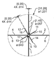
각 세트에서의 확장가능한 다리의 수는 약 2개 내지 약 20개, 약 4개 내지 약 15개, 약 4개 내지 약 10개, 약 5개 내지 약 10개의 범위이거나, 약 4개, 약 5개 또는 약 6개일 수 있다. 한 실시양태에서, 제1 세트에서의 확장가능한 다리의 수는 4개 (A, B, C 및 D)이고, 제2 세트에서의 다리의 수는 4개 (E, F, G 및 H)이고, 제3 세트에서의 다리의 수는 4개 (I, J, K 및 L)이고, 제4 세트에서의 다리의 수는 4개 (M, N, O 및 P)이다. 제1 세트에서의 확장가능한 다리는 약 0° 내지 약 90° (A), 약 90° 내지 약 180° (B), 약 180° 내지 약 270° (C), 약 270° 내지 약 360° (D)의 범위로 제2 튜브의 둘레를 따라 방사상 위치에 고정된다. 제1 세트의 확장가능한 다리 A, B, C 및 D의 방사상 위치는 대칭적일 수 있다. 제2 세트에서의 확장가능한 다리는 약 0° 내지 약 90° (E), 약 90° 내지 약 180° (F), 약 180° 내지 약 270° (G), 및 약 270° 내지 약 360° (H)의 제2 튜브의 둘레를 따라 방사상 위치에 고정된다. 제2 세트의 확장가능한 다리 E, F, G 및 H의 방사상 위치는 대칭적일 수 있다. 제2 세트의 확장가능한 다리의 방사상 위치는 제1 세트의 확장가능한 다리의 방사상 위치와 일치하지 않는다. 제3 세트에서의 확장가능한 다리는 약 0° 내지 약 90° (I), 약 90° 내지 약 180° (J), 약 180° 내지 약 270° (K), 약 270° 내지 약 360° (L)의 범위로 제2 튜브의 둘레를 따라 방사상 위치에 고정된다. 제3 세트의 확장가능한 다리 I, J, K 및 L의 방사상 위치는 대칭적일 수 있다. 제3 세트의 확장가능한 다리의 방사상 위치는 제1 세트의 확장가능한 다리의 방사상 위치에서 파생될 수 있다. 제4 세트에서의 확장가능한 다리는 약 0° 내지 약 90° (M), 약 90° 내지 약 180° (N), 약 180° 내지 약 270° (O), 및 약 270° 내지 약 360° (P)의 범위로 제2 튜브의 둘레를 따라 방사상 위치에 고정된다. 제4 세트의 확장가능한 다리 M, N, O 및 P의 방사상 위치는 대칭적일 수 있다. 제4 세트의 확장가능한 다리의 방사상 위치는 제2 세트의 확장가능한 다리의 방사상 위치에서 파생될 수 있다.The number of extendable legs in each set ranges from about 2 to about 20, about 4 to about 15, about 4 to about 10, about 5 to about 10, or about 4, about 5 Dogs or about six. In one embodiment, the number of extendable legs in the first set is four (A, B, C, and D), and the number of legs in the second set is four (E, F, G, and H) , The number of legs in the third set is four (I, J, K and L) and the number of legs in the fourth set is four (M, N, O and P). The extendable legs in the first set include about 0 ° to about 90 ° (A), about 90 ° to about 180 ° (B), about 180 ° to about 270 ° (C), about 270 ° to about 360 ° ( In the range of D) in a radial position along the circumference of the second tube. The radial positions of the first set of extendable legs A, B, C and D can be symmetrical. Extendable legs in the second set include about 0 ° to about 90 ° (E), about 90 ° to about 180 ° (F), about 180 ° to about 270 ° (G), and about 270 ° to about 360 ° It is fixed in a radial position along the perimeter of the second tube of (H). The radial positions of the second set of extendable legs E, F, G and H may be symmetrical. The radial position of the second set of extendable legs does not coincide with the radial position of the first set of extendable legs. The extendable legs in the third set include about 0 ° to about 90 ° (I), about 90 ° to about 180 ° (J), about 180 ° to about 270 ° (K), about 270 ° to about 360 ° ( In a range of L) along a circumference of the second tube. The radial positions of the third set of expandable legs I, J, K and L may be symmetrical. The radial position of the third set of extendable legs may be derived from the radial position of the first set of extendable legs. Extendable legs in the fourth set include about 0 ° to about 90 ° (M), about 90 ° to about 180 ° (N), about 180 ° to about 270 ° (O), and about 270 ° to about 360 ° It is fixed at a radial position along the circumference of the second tube in the range of (P). The radial positions of the fourth set of extendable legs M, N, O and P may be symmetrical. The radial position of the fourth set of extendable legs may be derived from the radial position of the second set of extendable legs.
추가적으로, 본 발명은 카테터를 혈관에 삽입하는 단계 (필터는 혈관 벽에 위치됨), 올가미가 노치를 붙잡을 때까지 올가미를 카테터를 통해 미는 단계, 올가미를 잡아당겨 필터에 장력을 가하는 단계, 각 확장가능한 다리가 혈관 벽에서 철거되며, 제3 및 제4 세트의 각 확장가능한 다리가 펴지고, 제2 세트의 각 확장가능한 다리가 혈관 벽에서 철거될 때까지 카테터를 올가미 및 제1 세트의 각 확장가능한 다리로 미는 단계, 제1, 제2, 제3 및 제4 세트의 확장가능한 다리를 카테터에 넣는 단계, 및 필터를 꺼내는 단계를 포함하는, 필터를 회수하기 위한 방법을 제공한다. 한 실시양태에서, 단부 중 하나로부터 필터의 회수를 위해 튜브의 각 단부에 하나의 노치가 있다. 별법으로, 필터는 유사한 메카니즘을 사용하여 다른 쪽의 단부로부터 회수할 수 있다.Additionally, the present invention provides a method of inserting a catheter into a blood vessel (the filter is located in the vessel wall), pushing the noose through the catheter until the snare catches the notch, pulling the noose to tension the filter, each expansion The catheter is noose and each extendable in the first set until the possible legs are dismantled from the vessel wall, each extendable leg of the third and fourth sets is stretched, and each extendable leg of the second set is removed from the vessel wall. A method for recovering a filter is provided, including pushing to a leg, inserting a first, second, third, and fourth set of expandable legs into the catheter, and removing the filter. In one embodiment, there is one notch at each end of the tube for recovery of the filter from one of the ends. Alternatively, the filter can be recovered from the other end using a similar mechanism.
추가적으로, 본 발명은 복수개의 제1 세트, 제2 세트 및 제3 세트의 슬롯을 갖는 제1 튜브, 복수개의 제1 세트, 제2 세트 및 제3 세트의 확장가능한 다리를 갖는 제2 튜브를 포함하는 필터를 제공한다. 제1 세트 및 제2 세트의 각 다리는 제2 튜브에 고정된 단부, 및 자유 단부를 갖는다. 제1 세트에서의 각 다리의 자유 단부는 제2 세트에서의 각 다리의 자유 단부와 마주보는 방향으로 배향된다. 제3 세트의 각 다리는 확장가능한 구획을 포함하며, 제2 튜브에 고정된 2개의 단부를 갖는다. 제1 튜브 상의 제1 세트의 슬롯은 제1 세트의 확장가능한 다리의 전개가 가능하도록 방사상 위치에 위치되며, 제1 튜브 상의 제2 세트의 슬롯은 제2 세트의 확장가능한 다리의 전개를 위해 위치되며, 제1 튜브 상의 제3 세트의 슬롯은 제3 세트의 각 다리에서의 확장가능한 구획의 전개를 위해 위치된다. 제1 튜브 상의 각 슬롯은 제1 튜브의 원통형 축과 평행하게 배향된다. 제2 튜브의 외부 직경은 제1 튜브의 내부 직경보다 작다. 필터는 제2 튜브를 제1 튜브에 삽입하여 형성된다. 제1 튜브의 하나 이상의 단부는 필터의 회수를 위해 하나 이상의 노치를 갖는다.Additionally, the present invention includes a first tube having a plurality of first sets, a second set, and a third set of slots, a second tube having a plurality of first sets, a second set, and a third set of extendable legs. To provide a filter. Each leg of the first set and the second set has an end fixed to the second tube, and a free end. The free end of each leg in the first set is oriented in a direction facing the free end of each leg in the second set. Each leg of the third set includes an expandable compartment and has two ends fixed to the second tube. The first set of slots on the first tube is positioned in a radial position to allow deployment of the first set of extendable legs, and the second set of slots on the first tube is positioned for deployment of the second set of expandable legs And a third set of slots on the first tube is positioned for deployment of the expandable compartment in each leg of the third set. Each slot on the first tube is oriented parallel to the cylindrical axis of the first tube. The outer diameter of the second tube is smaller than the inner diameter of the first tube. The filter is formed by inserting a second tube into the first tube. One or more ends of the first tube have one or more notches for recovery of the filter.
또한, 본 발명은 카테터를 혈관에 삽입하는 단계 (필터는 혈관 벽에 위치됨), 올가미가 노치를 붙잡을 때까지 올가미를 카테터를 통해 미는 단계, 올가미를 잡아당겨 필터에 장력을 가하는 단계, 각 확장가능한 다리가 혈관 벽에서 철거되며, 제3 세트의 각 확장가능한 다리가 펴지고, 제2 세트의 각 확장가능한 다리가 혈관 벽에서 철거될 때까지 카테터를 올가미 및 제1 세트의 각 확장가능한 다리로 미는 단계, 제1, 제2, 제3 및 제4 세트의 확장가능한 다리를 카테터에 넣는 단계, 및 필터를 꺼내는 단계를 포함하는, 필터를 회수하기 위한 방법을 제공한다. 별법으로, 필터는 유사한 메카니즘을 사용하여 다른 쪽의 단부로부터 회수할 수 있다.Further, the present invention provides a method of inserting a catheter into a blood vessel (the filter is located in the vessel wall), pushing the noose through the catheter until the snare catches the notch, pulling the noose to tension the filter, and expanding each Push the catheter to the lasso and the first set of each extendable leg until the possible legs are dismantled from the vessel wall, each extendable leg of the third set is straightened, and each extendable leg of the second set is removed from the vessel wall. A method for recovering a filter is provided, the method comprising the steps of: inserting a first, second, third, and fourth set of expandable legs into a catheter; and removing the filter. Alternatively, the filter can be recovered from the other end using a similar mechanism.
추가적으로, 본 발명은 복수개의 제1 세트의 슬롯 및 복수개의 제2 세트의 슬롯을 갖는 제1 튜브, 복수개의 제1 세트의 확장가능한 다리 및 복수개의 제2 세트의 확장가능한 다리를 갖는 제2 튜브를 포함하는 필터를 제공한다. 제1 세트 및 제2 세트의 각 다리는 제2 튜브에 고정된 단부, 및 자유 단부를 갖는다. 제1 세트에서의 각 다리의 자유 단부는 제2 세트에서의 각 다리의 자유 단부와 마주보는 방향으로 배향된다. 제1 튜브 상의 제1 세트의 슬롯은 제1 세트의 확장가능한 다리의 전개가 가능하도록 방사상 위치에 위치된다. 제1 튜브 상의 제2 세트의 슬롯은 제2 세트의 확장가능한 다리의 전개가 가능하도록 방사상 위치에 위치된다. 슬롯은 제1 튜브의 원통형 축과 평행하게 배향된다. 제2 튜브의 외부 직경은 제1 튜브의 내부 직경보다 작다. 필터는 제2 튜브를 제1 튜브로 삽입하여 형성된다. 제1 튜브의 하나 이상의 단부는 필터의 회수를 위한 하나 이상의 노치를 갖는다.Additionally, the present invention provides a first tube having a plurality of first sets of slots and a plurality of second sets of slots, a second tube having a plurality of first sets of extendable legs and a plurality of second sets of extendable legs. It provides a filter comprising a. Each leg of the first set and the second set has an end fixed to the second tube, and a free end. The free end of each leg in the first set is oriented in a direction facing the free end of each leg in the second set. The first set of slots on the first tube is positioned in a radial position to allow for deployment of the first set of expandable legs. The second set of slots on the first tube is positioned in a radial position to allow for deployment of the second set of expandable legs. The slot is oriented parallel to the cylindrical axis of the first tube. The outer diameter of the second tube is smaller than the inner diameter of the first tube. The filter is formed by inserting a second tube into the first tube. One or more ends of the first tube have one or more notches for recovery of the filter.
또한, 본 발명은 카테터를 혈관에 삽입하는 단계 (필터는 혈관 벽에 위치됨), 올가미가 제2 세트의 확장가능한 다리와 가까운 쪽의 제1 튜브 상의 노치를 붙잡을 때까지 올가미를 카테터 및 제2 튜브의 내부 공간을 통해 미는 단계, 올가미를 잡아당겨 필터에 장력을 가하는 단계, 각 확장가능한 다리가 혈관 벽에서 철거될 때까지 올가미를 제1 세트의 각 확장가능한 다리로 미는 단계, 제2 세트의 각 확장가능한 다리가 혈관 벽에서 철거될 때까지 올가미를 잡아당겨 제2 세트의 확장가능한 다리에 장력을 가하는 단계, 제1 및 제2 세트의 확장가능한 다리를 카테터에 넣는 단계, 및 필터를 꺼내는 단계를 포함하는, 필터를 회수하기 위한 방법을 제공한다. 별법으로, 필터는 유사한 메카니즘을 사용하여 다른 쪽의 단부로부터 회수할 수 있다.In addition, the present invention further comprises the steps of inserting the catheter into the vessel (the filter is located in the vessel wall), placing the noose on the catheter and second until the snare catches the notch on the first tube close to the second set of expandable legs. Pushing through the inner space of the tube, pulling the noose to tension the filter, pushing the noose onto the first set of each extendable leg until each extendable leg is removed from the vessel wall, the second set of Tensioning the second set of extendable legs by pulling the noose until each extendable leg is removed from the vessel wall, placing the first and second set of extendable legs into the catheter, and removing the filter It includes, a method for recovering the filter. Alternatively, the filter can be recovered from the other end using a similar mechanism.
추가적으로, 본 발명은 복수개의 제1 세트의 슬롯 및 복수개의 제1 세트의 확장가능한 다리를 갖는 제1 튜브, 복수개의 제2 세트의 슬롯 및 복수개의 제2 세트의 확장가능한 다리를 갖는 제2 튜브를 포함하는 필터를 제공한다. 제1 세트의 각 다리는 제1 튜브에 고정된 단부, 및 자유 단부를 갖는다. 제2 세트의 각 다리는 제2 튜브에 고정된 단부, 및 자유 단부를 갖는다. 제1 세트에서의 각 다리의 자유 단부는 제2 세트에서의 각 다리의 자유 단부와 마주보는 방향으로 배향된다. 제1 튜브 상의 제1 세트의 슬롯은 제2 튜브 상의 제2 세트의 확장가능한 다리의 전개가 가능하도록 방사상 위치에 위치되고; 제2 튜브 상의 제2 세트의 슬롯은 제1 튜브 상의 제1 세트의 확장가능한 다리의 전개를 위해 위치된다. 각 슬롯은 튜브의 원통형 축과 평행하게 배향된다. 필터는 제1 튜브 상의 제1 세트의 확장가능한 다리를 제2 튜브에 삽입하고, 제2 튜브 상의 제2 세트의 확장가능한 다리를 제1 튜브에 삽입하여 형성되어, 제1 튜브 상의 제1 세트의 확장가능한 다리는 제2 튜브 상의 제2 세트의 슬롯을 통해 전개되고, 제2 튜브 상의 제2 세트의 확장가능한 다리는 제1 튜브 상의 제1 세트의 슬롯을 통해 전개된다. 제1 또는 제2 튜브의 하나 이상의 단부는 필터의 회수를 위한 하나 이상의 노치를 갖는다. 또한, 본 발명은 카테터를 혈관에 삽입하는 단계 (필터는 혈관 벽에 위치됨), 올가미가 제2 세트의 확장가능한 다리와 가까운 쪽의 제2 튜브 상의 노치를 붙잡을 때까지 올가미를 카테터 및 필터의 내부 공간을 통해 미는 단계, 올가미를 잡아당겨 필터에 장력을 가하는 단계, 제1 세트의 각 확장가능한 다리가 혈관 벽에서 철거될 때까지 카테터를 제1 세트의 각 확장가능한 다리로 미는 단계, 제2 세트의 각 확장가능한 다리가 혈관 벽에서 철거될 때까지 올가미 및 제2 튜브를 잡아당겨 제2 세트의 확장가능한 다리에 장력을 가하는 단계, 제1 및 제2 세트의 확장가능한 다리를 카테터에 넣는 단계, 및 필터를 꺼내는 단계를 포함하는, 필터를 회수하기 위한 방법을 제공한다. 별법으로, 필터는 유사한 메카니즘을 사용하여 다른 쪽의 단부로부터 회수할 수 있다.Additionally, the present invention provides a first tube having a plurality of first sets of slots and a plurality of first sets of extendable legs, a second tube having a plurality of second sets of slots and a plurality of second sets of extendable legs. It provides a filter comprising a. Each leg of the first set has an end fixed to the first tube and a free end. Each leg of the second set has an end fixed to the second tube and a free end. The free end of each leg in the first set is oriented in a direction facing the free end of each leg in the second set. The first set of slots on the first tube is positioned in a radial position to allow deployment of the second set of expandable legs on the second tube; A second set of slots on the second tube is positioned for deployment of the first set of expandable legs on the first tube. Each slot is oriented parallel to the cylindrical axis of the tube. The filter is formed by inserting a first set of expandable legs on a first tube into a second tube and inserting a second set of expandable legs on a second tube into a first tube, thereby providing a first set of The extendable leg is deployed through a second set of slots on the second tube and the second set of expandable legs on the second tube is deployed through the first set of slots on the first tube. One or more ends of the first or second tube have one or more notches for recovery of the filter. In addition, the present invention provides a method of inserting a catheter into a blood vessel (the filter is located in the vessel wall), the snare of the catheter and the filter until the snare catches the notch on the second tube close to the second set of expandable legs. Pushing through the internal space, pulling the noose to tension the filter, pushing the catheter to each extendable leg of the first set until each extendable leg of the first set is removed from the vessel wall, a second Tensioning the second set of expandable legs by pulling the lasso and the second tube until each extendable leg of the set is removed from the vessel wall, and placing the first and second sets of extendable legs into the catheter And, removing the filter. Alternatively, the filter can be recovered from the other end using a similar mechanism.
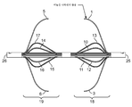
도 1a는 한 실시양태의 필터의 투시도를 나타낸다.
도 1b는 도 1a에서의 필터의 측면도를 나타낸다.
도 1c는 (25)에서 (26)으로 보았을 때 나타나는 것으로서 도 1a에서의 필터의 투시도를 나타낸다.
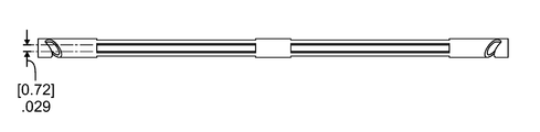
도 2a는 도 1a에서의 제1 튜브의 측면도를 나타낸다.
도 2b는 도 2a에서의 제1 튜브의 투시도를 나타낸다.
도 2c는 도 2a에서의 제1 튜브의 제2 투시도를 나타낸다.
도 2d는 (25)에서 (26)으로 보았을 때 나타나는 것으로서 도 2a에서의 제1 튜브의 투시도를 나타낸다.
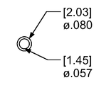
도 3a는 도 1a에서의 제2 튜브의 측면도를 나타낸다.
도 3b는 도 3a에서의 제2 튜브의 투시도를 나타낸다.
도 3c는 (28)에서 (29)로 보았을 때 나타나는 것으로서 도 3a에서의 제2 튜브의 투시도를 나타낸다.
도 4는 제3 및 제4 세트의 확장가능한 다리가 제3 튜브 또는 핀에 접합된 경우의 제2 튜브의 한 실시양태를 예시한다.
도 5는 미늘 디자인의 다양한 실시양태를 나타낸다.
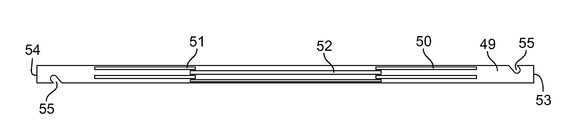
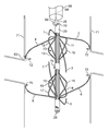
도 6a는 또 다른 실시양태의 필터의 측면도를 나타낸다.
도 6b는 도 6a에서의 필터의 투시도를 나타낸다.
도 6c는 (53)에서 (54)로 보았을 때 나타나는 것으로서 도 6a에서의 필터의 투시도를 나타낸다.
도 7은 도 6a에서의 필터의 제1 튜브의 측면도를 나타낸다.
도 8a는 도 6a에서의 필터의 제2 튜브의 측면도를 나타낸다.
도 8b는 (58)에서 (59)로 보았을 때 나타나는 것으로서 도 8a에서의 제2 튜브의 투시도를 나타낸다.
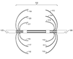
도 9a는 제3 실시양태의 필터의 투시도를 나타낸다.
도 9b는 도 9a에서의 필터의 측면도를 나타낸다.
도 9c는 (98)에서 (99)로 보았을 때 나타나는 것으로서 도 9a에서의 필터의 투시도를 나타낸다.
도 10은 도 9a에서의 필터의 제1 튜브의 측면도를 나타낸다.
도 11a는 도 9a에서의 필터의 제2 튜브의 측면도를 나타낸다.
도 11b는 (101)에서 (102)로 보았을 때 나타나는 것으로서 도 11a에서의 제2 튜브의 투시도를 나타낸다.
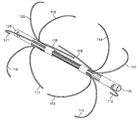
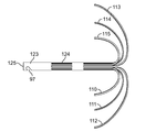
도 12a는 제4 실시양태의 필터의 투시도를 나타낸다.
도 12b는 도 12a에서의 필터의 측면도를 나타낸다.
도 12c는 (128)에서 (125)로 보았을 때 나타나는 것으로서 도 12a에서의 필터의 투시도를 나타낸다.
도 13은 도 12a에서의 필터의 제1 튜브의 측면도를 나타낸다.
도 14는 도 12a에서의 필터의 제2 튜브의 측면도를 나타낸다.
도 15는 하대정맥에서의 도 1a에서의 필터의 전개를 나타낸다.
도 16은 도 1a에서 나타낸 필터의 회수를 나타낸다.
도 17은 다양한 형태의 노치의 외형을 나타낸다.
도 18은 도 6a에서 나타낸 필터의 회수를 나타낸다.
도 19는 도 9a에서 나타낸 필터의 회수를 나타낸다.1A shows a perspective view of a filter of one embodiment.
FIG. 1B shows a side view of the filter in FIG. 1A.
FIG. 1C shows a perspective view of the filter in FIG. 1A as seen from (25) to (26).
2A shows a side view of the first tube in FIG. 1A.
FIG. 2B shows a perspective view of the first tube in FIG. 2A.
FIG. 2C shows a second perspective view of the first tube in FIG. 2A.
FIG. 2D shows a perspective view of the first tube in FIG. 2A as seen from (25) to (26).
3A shows a side view of the second tube in FIG. 1A.
FIG. 3B shows a perspective view of the second tube in FIG. 3A.
3C shows a perspective view of the second tube in FIG. 3A as seen from (28) to (29).
4 illustrates one embodiment of a second tube when the third and fourth sets of expandable legs are joined to a third tube or fin.
5 shows various embodiments of the barb design.
6A shows a side view of a filter of another embodiment.
FIG. 6B shows a perspective view of the filter in FIG. 6A.
FIG. 6C shows a perspective view of the filter in FIG. 6A as seen from 53 to 54. FIG.
FIG. 7 shows a side view of the first tube of the filter in FIG. 6A.
8A shows a side view of the second tube of the filter in FIG. 6A.
FIG. 8B shows a perspective view of the second tube in FIG. 8A as seen from 58 to 59.
9A shows a perspective view of a filter of the third embodiment.
9B shows a side view of the filter in FIG. 9A.
FIG. 9C shows a perspective view of the filter in FIG. 9A as seen from (98) to (99).
FIG. 10 shows a side view of the first tube of the filter in FIG. 9A.
FIG. 11A shows a side view of the second tube of the filter in FIG. 9A.
FIG. 11B shows a perspective view of the second tube in FIG. 11A as seen from 101 to 102.
12A shows a perspective view of a filter of the fourth embodiment.
12B shows a side view of the filter in FIG. 12A.
FIG. 12C shows a perspective view of the filter in FIG. 12A as seen from 128 to 125.
FIG. 13 shows a side view of the first tube of the filter in FIG. 12A.
FIG. 14 shows a side view of the second tube of the filter in FIG. 12A.
FIG. 15 shows the development of the filter in FIG. 1A in the inferior vena cava. FIG.
FIG. 16 shows the number of filters shown in FIG. 1A.
17 shows the appearance of various types of notches.
FIG. 18 shows the number of filters shown in FIG. 6A.
FIG. 19 shows the number of filters shown in FIG. 9A.
본 발명은 영구적이거나 회수가능할 수 있으며, 폐 색전증 (PE)의 일시적 또는 영구적인 예방을 위해 사용할 수 있는 대정맥 필터 ("필터")를 제공한다. 필터는 정맥, 예컨대 대퇴 정맥을 통해 신체에 경피적으로 삽입할 수 있다. 필터는 전개시에 겹쳐지거나 또는 겹쳐지지 않을 수 있는, 반구체를 초래할 수 있는 튜브-내-튜브 구조를 갖는다. 반구체는 전개시에 함께 케이지를 형성한다. 필터는 대정맥 내의 신장 정맥의 연결부 또는 그 아래에 위치된다. 필터의 반구체 또는 케이지는 안정하며 이동하지 않는 대정맥 여과를 보장한다. 반구체는 접혀질 수 있기 때문에, 필터는 대정맥으로부터 쉽게 회수될 수 있다. 게다가, 본 발명 필터의 디자인은 단부 중 하나로부터 필터를 회수할 수 있도록 한다.The present invention provides a venous vein filter (“filter”), which may be permanent or recoverable, and which may be used for the temporary or permanent prevention of pulmonary embolism (PE). The filter may be inserted percutaneously into the body through a vein, such as a femoral vein. The filter has an in-tube structure that can result in hemispheres, which may or may not overlap upon deployment. The hemispheres together form a cage when deployed. The filter is located at or below the connection of the renal vein in the vena cava. The hemispherical or cage of the filter ensures stable and immobile venous filtration. Since the hemispheres can be folded, the filter can be easily recovered from the vena cava. In addition, the design of the filter of the present invention makes it possible to recover the filter from one of its ends.
필터는 제1 튜브 및 제2 튜브로부터 형성될 수 있다. 제1 튜브는 복수개의 제1 세트의 슬롯, 복수개의 제2 세트의 슬롯, 복수개의 제3 세트의 슬롯 및 복수개의 제4 세트의 슬롯을 갖는다. 제2 튜브는 복수개의 제1 세트의 확장가능한 다리, 복수개의 제2 세트의 확장가능한 다리, 복수개의 제3 세트의 확장가능한 다리 및 복수개의 제4 세트의 확장가능한 다리를 갖는다. 제1 세트 및 제2 세트의 각 다리는 제2 튜브에 고정된 단부, 및 자유 단부를 갖는다. 제1 세트에서의 각 다리의 자유 단부는 제2 세트에서의 각 다리의 자유 단부와 마주보는 방향으로 배향된다. 제3 세트 및 제4 세트의 각 다리는 확장가능한 구획을 포함하며, 제2 튜브에 고정된 2개의 단부를 갖는다. 제3 세트 및 제4 세트의 각 확장가능한 다리의 구획은 제2 튜브 내에 있는 핀 또는 튜브에 부착되거나 또는 고정될 수 있다. 한 세트의 확장가능한 다리의 방사상 위치는 상이한 세트의 확장가능한 다리의 방사상 위치에서 파생될 수 있거나, 또는 그와 동일할 수 있다. 예를 들어, 제3 세트의 확장가능한 다리의 방사상 위치는 제1 세트의 확장가능한 다리의 방사상 위치에서 파생될 수 있거나, 또는 그와 동일할 수 있다. 제4 세트의 확장가능한 다리의 방사상 위치는 제2 세트의 확장가능한 다리의 방사상 위치에서 파생될 수 있거나, 또는 그와 동일할 수 있다. 제1 튜브 상의 제1 세트의 슬롯의 각 슬롯은 제1 세트의 각 확장가능한 다리의 전개가 가능하도록 방사상 위치에 위치된다. 제1 튜브 상의 제2 세트의 슬롯의 각 슬롯은 제2 세트의 각 확장가능한 다리의 전개가 가능하도록 방사상 위치에 위치된다. 제1 튜브 상의 제3 세트의 슬롯의 각 슬롯은 제3 세트의 확장가능한 다리의 각 다리에서의 확장가능한 구획의 전개가 가능하도록 방사상 위치에 위치된다. 제1 튜브 상의 제4 세트의 슬롯의 각 슬롯은 제4 세트의 확장가능한 다리의 각 다리에서의 확장가능한 구획의 전개가 가능하도록 방사상 위치에 위치된다. 제1 튜브 상의 각 슬롯은 제1 튜브의 원통형 축과 평행하게 배향된다. 제2 튜브의 외부 직경은 제2 튜브가 제1 튜브에 삽입되는 것이 가능하도록 제1 튜브의 내부 직경보다 작을 수 있다. 제1 튜브의 직경은 제2 튜브의 직경과 동일하거나 또는 상이할 수 있다.The filter may be formed from the first tube and the second tube. The first tube has a plurality of first sets of slots, a plurality of second sets of slots, a plurality of third sets of slots, and a plurality of fourth sets of slots. The second tube has a plurality of first sets of extendable legs, a plurality of second sets of extendable legs, a plurality of third sets of extendable legs and a plurality of fourth sets of extendable legs. Each leg of the first set and the second set has an end fixed to the second tube, and a free end. The free end of each leg in the first set is oriented in a direction facing the free end of each leg in the second set. Each leg of the third set and the fourth set includes an expandable compartment and has two ends fixed to the second tube. The sections of each extendable leg of the third and fourth sets may be attached or secured to a pin or tube in the second tube. The radial position of one set of extendable legs may be derived from, or may be the same as, the radial position of the different set of extendable legs. For example, the radial position of the third set of extendable legs may be derived from or may be the same as the radial position of the first set of extendable legs. The radial position of the fourth set of extendable legs may be derived from or may be the same as the radial position of the second set of extendable legs. Each slot of the first set of slots on the first tube is positioned in a radial position to allow deployment of each expandable leg of the first set. Each slot of the second set of slots on the first tube is positioned in a radial position to allow deployment of each expandable leg of the second set. Each slot of the third set of slots on the first tube is positioned in a radial position to allow for deployment of the expandable compartment in each leg of the third set of expandable legs. Each slot of the fourth set of slots on the first tube is positioned in a radial position to allow deployment of the expandable compartment in each leg of the fourth set of expandable legs. Each slot on the first tube is oriented parallel to the cylindrical axis of the first tube. The outer diameter of the second tube may be smaller than the inner diameter of the first tube to allow the second tube to be inserted into the first tube. The diameter of the first tube may be the same or different than the diameter of the second tube.
한 실시양태에서, 제1 세트에서의 확장가능한 다리의 수는 4개 (A, B, C 및 D)이고, 제2 세트에서의 다리의 수는 4개 (E, F, G 및 H)이고, 제3 세트에서의 다리의 수는 4개 (I, J, K 및 L)이고, 제4 세트에서의 다리의 수는 4개 (M, N, O 및 P)이다. 제1 세트에서의 확장가능한 다리는 약 0° 내지 약 90° (A), 약 90° 내지 약 180° (B), 약 180° 내지 약 270° (C), 약 270° 내지 약 360° (D) 범위로 제2 튜브의 둘레를 따라 방사상 위치에 고정된다. 한 실시양태에서, 제1 세트의 확장가능한 다리의 방사상 위치는 대칭적이며, 예를 들어 A는 0°에 있고, B는 90°에 있고, C는 180°에 있고, D는 270°에 있다. 제1 세트의 확장가능한 다리의 방사상 위치는 또한 비대칭적일 수도 있다.In one embodiment, the number of extendable legs in the first set is four (A, B, C, and D), and the number of legs in the second set is four (E, F, G, and H) , The number of legs in the third set is four (I, J, K and L) and the number of legs in the fourth set is four (M, N, O and P). The extendable legs in the first set include about 0 ° to about 90 ° (A), about 90 ° to about 180 ° (B), about 180 ° to about 270 ° (C), about 270 ° to about 360 ° ( D) to a radial position along the circumference of the second tube. In one embodiment, the radial position of the first set of extendable legs is symmetric, for example A is at 0 °, B is at 90 °, C is at 180 °, and D is at 270 °. . The radial position of the first set of expandable legs may also be asymmetric.
추가의 실시양태에서, 제3 세트에서의 확장가능한 다리는 약 0° 내지 약 90° (I), 약 90° 내지 약 180° (J), 약 180° 내지 약 270° (K), 약 270° 내지 약 360° (L) 범위로 제2 튜브의 둘레를 따라 방사상 위치에 고정된다. 제3 세트의 확장가능한 다리 I, J, K 및 L의 방사상 위치는 대칭적이거나 또는 비대칭적일 수 있다. 제3 세트의 확장가능한 다리의 방사상 위치는 제1 세트의 확장가능한 다리의 방사상 위치에서 파생될 수 있다. 예를 들어, 제1 세트의 확장가능한 다리의 방사상 위치가 0°(A), 90°(B), 180°(C) 및 270°(D)이고, 제3 세트의 확장가능한 다리가 제1 세트의 확장가능한 다리에서 10°파생된 경우에, 제3 세트의 확장가능한 다리는 약 10° (I), 약 100° (J), 약 190° (K) 및 약 280° (L)에 위치된다. 제3 세트의 확장가능한 다리의 방사상 위치는 제1 세트의 확장가능한 다리와 대칭적 또는 비대칭적으로 상이하거나 동일할 수 있다.In further embodiments, the extendable legs in the third set range from about 0 ° to about 90 ° (I), about 90 ° to about 180 ° (J), about 180 ° to about 270 ° (K), about 270 It is fixed in a radial position along the circumference of the second tube in the range of from about 360 ° (L). The radial positions of the third set of expandable legs I, J, K and L may be symmetrical or asymmetrical. The radial position of the third set of extendable legs may be derived from the radial position of the first set of extendable legs. For example, the radial positions of the first set of extendable legs are 0 ° (A), 90 ° (B), 180 ° (C), and 270 ° (D), and the third set of extendable legs is the first If derived from the extendable legs of the set 10 °, the third set of extendable legs is located at about 10 ° (I), about 100 ° (J), about 190 ° (K) and about 280 ° (L) do. The radial position of the third set of extendable legs may be different or the same as symmetrically or asymmetrically with the first set of extendable legs.
제3 실시양태에서, 제2 세트에서의 다리는 약 0° 내지 약 90° (E), 약 90° 내지 약 180° (F), 약 180° 내지 약 270° (G), 및 약 270° 내지 약 360° (H) 범위로 제2 튜브의 둘레를 따라 방사상 위치에 고정된다. 제2 세트의 확장가능한 다리 E, F, G 및 H의 방사상 위치는 대칭적이거나 또는 비대칭적일 수 있다. 제2 세트의 확장가능한 다리 E, F, G 및 H의 방사상 위치는 제1 세트의 확장가능한 다리 A, B, C 및 D의 방사상 위치와 동일하거나 또는 상이할 수 있다.In a third embodiment, the legs in the second set have about 0 ° to about 90 ° (E), about 90 ° to about 180 ° (F), about 180 ° to about 270 ° (G), and about 270 ° And in a radial position along the circumference of the second tube in the range from about 360 ° (H). The radial positions of the second set of extendable legs E, F, G and H can be symmetrical or asymmetrical. The radial positions of the second set of extendable legs E, F, G, and H may be the same or different from the radial positions of the first set of extendable legs A, B, C, and D.
제4 실시양태에서, 제4 세트에서의 확장가능한 다리는 약 0° 내지 약 90° (M), 약 90° 내지 약 180° (N), 약 180° 내지 약 270° (O), 및 약 270° 내지 약 360° (P) 범위로 제2 튜브의 둘레를 따라 방사상 위치에 고정된다. 제4 세트의 확장가능한 다리 M, N, O 및 P의 방사상 위치는 대칭적이거나 또는 비대칭적일 수 있다. 제4 세트의 확장가능한 다리의 방사상 위치는 제2 세트의 확장가능한 다리의 방사상 위치에서 파생될 수 있다. 예를 들어, 제2 세트의 확장가능한 다리의 방사상 위치가 0° (E), 90° (F), 180° (G) 및 270° (H)이고, 제4 세트의 확장가능한 다리가 제1 세트의 확장가능한 다리에서 10° 파생된 경우에, 제3 세트의 확장가능한 다리는 약 10° (M), 약 100° (N), 약 190° (O) 및 약 280° (P)에 위치된다. 제4 세트의 확장가능한 다리의 방사상 위치는 제2 세트의 확장가능한 다리와 대칭적 또는 비대칭적으로 상이하거나 동일할 수 있다.In a fourth embodiment, the extendable legs in the fourth set include from about 0 ° to about 90 ° (M), about 90 ° to about 180 ° (N), about 180 ° to about 270 ° (O), and about It is fixed in a radial position along the circumference of the second tube in the range of 270 ° to about 360 ° (P). The radial positions of the fourth set of expandable legs M, N, O and P may be symmetrical or asymmetrical. The radial position of the fourth set of extendable legs may be derived from the radial position of the second set of extendable legs. For example, the radial positions of the second set of extendable legs are 0 ° (E), 90 ° (F), 180 ° (G), and 270 ° (H), and the fourth set of extendable legs is the first If derived from the set's
제2 세트의 확장가능한 다리의 방사상 위치는 제1 세트의 확장가능한 다리의 방사상 위치와 동일하거나, 또는 그에서 파생될 수 있다. 제4 세트의 확장가능한 다리의 방사상 위치는 제3 세트의 확장가능한 다리의 방사상 위치와 동일하거나, 또는 그에서 파생될 수 있다. 한 실시양태에서, 제2 세트의 확장가능한 다리의 방사상 위치는 제1 세트의 확장가능한 다리의 방사상 위치와 동일하고; 제3 세트의 확장가능한 다리의 방사상 위치는 제1 세트의 확장가능한 다리의 방사상 위치에서 파생되고; 제4 세트의 확장가능한 다리의 방사상 위치는 제3 세트의 확장가능한 다리의 방사상 위치와 동일하다. 제1 세트에서의 각 다리의 자유 단부는 제2 세트에서의 각 다리의 자유 단부와 마주보는 방향으로 배향될 수 있다. 별법으로, 제1 세트에서의 각 다리의 자유 단부는 제2 세트에서의 각 다리의 자유 단부의 방향과 동일한 방향으로 배향될 수 있다.The radial position of the second set of extendable legs may be the same as or derived from the radial position of the first set of extendable legs. The radial position of the fourth set of extendable legs may be the same as or derived from the radial position of the third set of extendable legs. In one embodiment, the radial position of the second set of extendable legs is the same as the radial position of the first set of extendable legs; The radial position of the third set of extendable legs is derived from the radial position of the first set of extendable legs; The radial position of the fourth set of extendable legs is the same as the radial position of the third set of extendable legs. The free end of each leg in the first set may be oriented in a direction facing the free end of each leg in the second set. Alternatively, the free end of each leg in the first set may be oriented in the same direction as the direction of the free end of each leg in the second set.
추가적으로, 본 발명은 복수개의 제1 세트의 슬롯, 복수개의 제2 세트의 슬롯 및 복수개의 제3 세트의 슬롯을 갖는 제1 튜브, 및 복수개의 제1 세트의 확장가능한 다리, 복수개의 제2 세트의 확장가능한 다리 및 복수개의 제3 세트의 확장가능한 다리를 갖는 제2 튜브를 포함하는 필터를 제공한다. 제1 세트 및 제2 세트의 각 다리는 제2 튜브에 고정된 단부, 및 자유 단부를 갖는다. 제1 세트에서의 각 다리의 자유 단부는 제2 세트에서의 각 다리의 자유 단부와 마주보는 방향으로 배향된다. 제3 세트의 각 다리는 확장가능한 구획을 포함하며, 제2 튜브에 고정된 2개의 단부를 갖는다. 제1 튜브 상의 제1 세트의 슬롯은 제1 세트의 확장가능한 다리의 전개가 가능하도록 방사상 위치에 위치된다. 제1 튜브 상의 제2 세트의 슬롯은 제2 세트의 확장가능한 다리의 전개가 가능하도록 방사상 위치에 위치된다. 제1 튜브 상의 제3 세트의 슬롯은 제3 세트의 확장가능한 구획의 전개가 가능하도록 방사상 위치에 위치된다. 제1 튜브 상의 각 슬롯은 제1 튜브의 원통형 축과 평행하게 배향된다. 한 세트의 확장가능한 다리의 방사상 위치는 상이한 세트의 확장가능한 다리의 방사상 위치에서 파생될 수 있거나, 또는 그와 동일할 수 있다. 예를 들어, 제2 세트의 확장가능한 다리의 방사상 위치는 제1 세트의 확장가능한 다리의 방사상 위치와 동일하거나, 또는 그에서 파생될 수 있다. 제3 세트의 확장가능한 다리의 방사상 위치는 제1 세트의 확장가능한 다리의 방사상 위치와 동일하거나, 또는 그에서 파생될 수 있다. 한 실시양태에서, 제2 세트의 확장가능한 다리의 방사상 위치는 제1 세트의 확장가능한 다리의 방사상 위치와 동일하고, 제3 세트의 확장가능한 다리의 방사상 위치는 제1 세트의 확장가능한 다리의 방사상 위치에서 파생된다. 제2 튜브의 외부 직경은 제1 튜브의 내부 직경보다 작을 수 있다. 필터는 제2 튜브를 제1 튜브에 삽입하여 형성될 수 있다. 제1 튜브의 직경은 제2 튜브의 직경과 동일하거나 또는 상이할 수 있다. 제1 세트에서의 각 다리의 자유 단부는 제2 세트에서의 각 다리의 자유 단부와 마주보는 방향으로 배향될 수 있다. 별법으로, 제1 세트에서의 각 다리의 자유 단부는 제2 세트에서의 각 다리의 자유 단부의 방향과 동일한 방향으로 배향될 수 있다.Additionally, the invention provides a first tube having a plurality of first sets of slots, a plurality of second sets of slots and a plurality of third sets of slots, and a plurality of first sets of extendable legs, a plurality of second sets. And a second tube having an expandable leg and a plurality of third sets of extendable legs. Each leg of the first set and the second set has an end fixed to the second tube, and a free end. The free end of each leg in the first set is oriented in a direction facing the free end of each leg in the second set. Each leg of the third set includes an expandable compartment and has two ends fixed to the second tube. The first set of slots on the first tube is positioned in a radial position to allow for deployment of the first set of expandable legs. The second set of slots on the first tube is positioned in a radial position to allow for deployment of the second set of expandable legs. The third set of slots on the first tube is positioned in a radial position to allow deployment of the third set of expandable compartments. Each slot on the first tube is oriented parallel to the cylindrical axis of the first tube. The radial position of one set of extendable legs may be derived from, or may be the same as, the radial position of the different set of extendable legs. For example, the radial position of the second set of extendable legs may be the same as or derived from the radial position of the first set of extendable legs. The radial position of the third set of extendable legs may be the same as or derived from the radial position of the first set of extendable legs. In one embodiment, the radial position of the second set of extendable legs is the same as the radial position of the first set of extendable legs and the radial position of the third set of extendable legs is radial to the first set of extendable legs. Is derived from the location. The outer diameter of the second tube may be smaller than the inner diameter of the first tube. The filter may be formed by inserting a second tube into the first tube. The diameter of the first tube may be the same or different than the diameter of the second tube. The free end of each leg in the first set may be oriented in a direction facing the free end of each leg in the second set. Alternatively, the free end of each leg in the first set may be oriented in the same direction as the direction of the free end of each leg in the second set.
또한, 본 발명은 복수개의 제1 세트의 슬롯 및 복수개의 제2 세트의 슬롯을 갖는 제1 튜브, 및 복수개의 제1 세트의 확장가능한 다리 및 복수개의 제2 세트의 확장가능한 다리를 갖는 제2 튜브를 포함하는 필터를 제공한다. 제1 세트 및 제2 세트의 각 다리는 제2 튜브에 고정된 단부, 및 자유 단부를 갖는다. 제1 세트에서의 각 다리의 자유 단부는 제2 세트에서의 각 다리의 자유 단부와 마주보는 방향으로 배향된다. 제1 튜브 상의 제1 세트의 슬롯은 제1 세트의 확장가능한 다리의 전개가 가능하도록 방사상 위치에 위치된다. 제1 튜브 상의 제2 세트의 슬롯은 제2 세트의 확장가능한 다리의 전개가 가능하도록 방사상 위치에 위치된다. 제1 튜브 상의 각 슬롯은 제1 튜브의 원통형 축과 평행하게 배향된다. 제2 세트의 확장가능한 다리의 방사상 위치는 제1 세트의 확장가능한 다리의 방사상 위치와 동일하거나, 또는 그에서 파생될 수 있다. 한 실시양태에서, 제2 세트의 확장가능한 다리의 방사상 위치는 제1 세트의 확장가능한 다리의 방사상 위치와 동일하다. 제2 튜브의 외부 직경은 제1 튜브의 내부 직경보다 작을 수 있다. 필터는 제2 튜브를 제1 튜브에 삽입하여 형성될 수 있다. 제1 세트에서의 각 다리의 자유 단부는 제2 세트에서의 각 다리의 자유 단부와 마주보는 방향으로 배향될 수 있다. 별법으로, 제1 세트에서의 각 다리의 자유 단부는 제2 세트에서의 각 다리의 자유 단부의 방향과 동일한 방향으로 배향될 수 있다.The invention also relates to a first tube having a plurality of first sets of slots and a plurality of second sets of slots, and a second having a plurality of first sets of expandable legs and a plurality of second sets of extendable legs. Provide a filter comprising a tube. Each leg of the first set and the second set has an end fixed to the second tube, and a free end. The free end of each leg in the first set is oriented in a direction facing the free end of each leg in the second set. The first set of slots on the first tube is positioned in a radial position to allow for deployment of the first set of expandable legs. The second set of slots on the first tube is positioned in a radial position to allow for deployment of the second set of expandable legs. Each slot on the first tube is oriented parallel to the cylindrical axis of the first tube. The radial position of the second set of extendable legs may be the same as or derived from the radial position of the first set of extendable legs. In one embodiment, the radial position of the second set of extendable legs is the same as the radial position of the first set of extendable legs. The outer diameter of the second tube may be smaller than the inner diameter of the first tube. The filter may be formed by inserting a second tube into the first tube. The free end of each leg in the first set may be oriented in a direction facing the free end of each leg in the second set. Alternatively, the free end of each leg in the first set may be oriented in the same direction as the direction of the free end of each leg in the second set.
제1 및 제2 세트의 확장가능한 다리를 포함하는 케이지가 형성될 수 있다. 제1 및 제2 세트의 확장가능한 다리가 전개되는 경우에, 케이지는 구체 형상을 형성할 수 있다. 제3 또는 제4 세트에서의 확장가능한 다리의 확장가능한 구획은 전개되는 경우에 곡선 형상을 형성할 수 있다. 제3 또는 제4 세트의 각 확장가능한 다리의 구획은 제2 튜브 내에 있는 핀 또는 튜브에 부착되거나 또는 고정될 수 있다.A cage can be formed that includes the first and second sets of expandable legs. When the first and second sets of expandable legs are deployed, the cage may form a spherical shape. The expandable section of the expandable leg in the third or fourth set may form a curved shape when deployed. The sections of each expandable leg of the third or fourth set may be attached or secured to a pin or tube in the second tube.
본 발명의 추가의 실시양태에서, 제1 튜브의 하나 이상의 단부는 하나 이상의 노치를 갖는다. 바람직한 실시양태에서, 단부 중 하나로부터의 필터의 회수를 위해 제1 튜브의 각 단부에 하나의 노치가 있다. 대정맥으로의 삽입 이전에, 필터를 카테터에 넣을 수 있다. 각 확장가능한 다리의 자유 단부는 하나 이상의 미늘을 가질 수 있다. 다리는 직사각형 조각, 와이어, 튜브, 막대, 실 또는 임의의 다른 목적하는 구조를 비롯한 다양한 형상을 가질 수 있다. 다리는 직선형이거나, 곡선형이거나, 가늘어지거나, 또는 다수의 모서리를 가질 수 있다. 예를 들어, 다리는 그의 자유 단부에서 안쪽으로 굽혀져서 혈관 벽으로의 침투를 줄일 수 있다. 각 다리의 여러 부분의 형상, 외형 또는 크기는 상이하거나 또는 동일할 수 있다. 필터의 상이한 다리의 형상, 외형, 크기 또는 각도는 상이하거나 또는 동일할 수 있다. 다리에는 노치, 미늘, 후크 (hook), 또는 필터의 회수를 방해하지 않고 다리를 혈관 벽에 고정시키는 임의의 다른 구조가 있을 수 있다. 각 세트에서의 확장가능한 다리의 수는 2개 내지 20개, 4개 내지 15개, 4개 내지 10개, 또는 5개 내지 10개의 범위일 수 있다. 각 세트에서의 다리의 수는 3개, 4개, 5개, 6개일 수 있거나, 또는 전개되는 경우에 필터의 안정성을 보장하며 효율적인 대정맥 여과를 보장할 수 있는 임의의 다른 수일 수 있다. 각각의 제1, 제2, 제3 및 제4 세트에서의 다리의 수는 동일하거나 또는 동일하지 않을 수 있다. 다리는 튜브의 둘레를 따라 방사상 위치에 대칭적 또는 비대칭적으로 위치될 수 있다. 다리가 대칭적으로 위치되는 경우에, 각 다리 쌍, 예를 들어 A-B 및 B-C 사이의 방사상 길이는 동일하다. 본원에서의 다리에 대해 열거된 방사상 위치는 단지 예시 목적으로만 제공되며, 다리는 튜브의 둘레를 따라 임의의 지점에서 과도한 실험 없이 당업자들에 의해 위치될 수 있다. 예를 들어, 제1 확장가능한 세트에 8개 다리가 있는 경우에, 다리의 위치 결정은 360°를 N으로 나누어 결정할 수 있으며, 여기서 N은 다리의 수이다. N = 8인 경우에, 다리는 튜브의 둘레를 따라 45° 간격으로 대칭적으로 위치될 수 있다. 그렇다면, 확장가능한 다리는 둘레 상에서 45°간격으로 떨어진 파생 간격으로, 즉 0° (360°), 45°, 90°, 135°, 180°, 225°, 270°, 315°에 위치될 수 있다.In a further embodiment of the invention, at least one end of the first tube has at least one notch. In a preferred embodiment, there is one notch at each end of the first tube for recovery of the filter from one of the ends. Prior to insertion into the vena cava, the filter may be placed in the catheter. The free end of each extendable leg may have one or more barbs. The legs may have various shapes, including rectangular pieces, wires, tubes, rods, threads, or any other desired structure. The legs may be straight, curved, tapered, or have multiple edges. For example, a leg can be bent inward at its free end to reduce penetration into the vessel wall. The shape, shape or size of the various parts of each leg may be different or the same. The shape, shape, size or angle of the different legs of the filter may be different or the same. The legs may have notches, barbs, hooks, or any other structure that secures the legs to the vessel wall without disturbing the recovery of the filter. The number of extendable legs in each set can range from 2 to 20, 4 to 15, 4 to 10, or 5 to 10. The number of legs in each set can be three, four, five, six, or any other number that can ensure the stability of the filter and ensure efficient venous filtration when deployed. The number of legs in each of the first, second, third and fourth sets may or may not be the same. The legs may be located symmetrically or asymmetrically in radial positions along the circumference of the tube. If the legs are located symmetrically, the radial length between each pair of legs, for example A-B and B-C, is the same. The radial positions listed for the legs herein are provided for illustrative purposes only, and the legs may be positioned by those skilled in the art without undue experimentation at any point along the circumference of the tube. For example, if there are eight legs in the first expandable set, the positioning of the legs can be determined by dividing 360 ° by N, where N is the number of legs. In the case of N = 8, the legs can be symmetrically positioned at 45 ° intervals along the circumference of the tube. If so, the extendable legs may be positioned at derived intervals spaced 45 ° apart on the perimeter, i.e. 0 ° (360 °), 45 °, 90 °, 135 °, 180 °, 225 °, 270 °, 315 °. .
추가적으로, 본 발명은 복수개의 제1 세트의 슬롯 및 복수개의 제1 세트의 확장가능한 다리를 갖는 제1 튜브, 및 복수개의 제2 세트의 슬롯 및 복수개의 제2 세트의 확장가능한 다리를 갖는 제2 튜브를 포함하는 필터를 제공한다. 제1 세트의 각 다리는 제1 튜브에 고정된 단부, 및 자유 단부를 갖는다. 제2 세트의 각 다리는 제2 튜브에 고정된 단부, 및 자유 단부를 갖는다. 제1 세트에서의 각 다리의 자유 단부는 제2 세트에서의 각 다리의 자유 단부와 마주보는 방향으로 배향된다. 제1 튜브 상의 제1 세트의 슬롯은 제2 튜브 상의 제2 세트의 확장가능한 다리의 전개가 가능하도록 방사상 위치에 위치되며, 제2 튜브 상의 제2 세트의 슬롯은 제1 튜브 상의 제1 세트의 확장가능한 다리의 전개를 위해 위치된다. 각 슬롯은 튜브의 원통형 축과 평행하게 배향된다. 제1 세트의 슬롯의 방사상 위치는 제1 튜브 상의 제1 세트의 확장가능한 다리의 방사상 위치에서 파생된다. 제2 세트의 슬롯의 방사상 위치는 제2 튜브 상의 제2 세트의 확장가능한 다리의 방사상 위치에서 파생된다. 제1 튜브의 직경은 제2 튜브의 직경과 동일하거나 또는 상이할 수 있다. 필터는 제1 세트의 확장가능한 다리를 제2 튜브에 삽입하고, 제2 세트의 확장가능한 다리를 제1 튜브에 삽입하여 형성되어, 제1 튜브 상의 제1 세트의 확장가능한 다리는 제2 튜브 상의 제2 세트의 슬롯을 통해 전개되며, 제2 튜브 상의 제2 세트의 확장가능한 다리는 제1 튜브 상의 제1 세트의 슬롯을 통해 전개된다. 전개 후에, 제1 세트에서의 각 다리의 자유 단부는 제2 세트에서의 각 다리의 자유 단부와 마주보는 방향으로 배향된다. 제1 또는 제2 튜브의 하나 이상의 단부는 필터의 회수를 위한 하나 이상의 노치를 갖는다. 제1 및 제2 세트의 확장가능한 다리를 포함하는 케이지가 형성될 수 있다. 케이지는 제1 및 제2 세트의 확장가능한 다리가 전개되는 경우에 구체 형상을 형성할 수 있다. 본 발명의 추가의 실시양태에서, 제1 튜브의 한쪽 단부 및/또는 제2 튜브의 한쪽 단부는 하나 이상의 노치를 갖는다. 바람직한 실시양태에서, 제1 튜브의 한쪽 단부에 하나의 노치가 있으며, 단부 중 하나로부터 필터의 회수를 위해 제2 튜브의 한쪽 단부에 하나의 노치가 있다. 제1 세트에서의 각 다리의 자유 단부는 제2 세트에서의 각 다리의 자유 단부와 마주보는 방향으로 배향될 수 있다. 별법으로, 제1 세트에서의 각 다리의 자유 단부는 제2 세트에서의 각 다리의 자유 단부의 방향과 동일한 방향으로 배향될 수 있다.Additionally, the invention provides a first tube having a plurality of first sets of slots and a plurality of first sets of extendable legs, and a second having a plurality of second sets of slots and a plurality of second sets of extendable legs. Provide a filter comprising a tube. Each leg of the first set has an end fixed to the first tube and a free end. Each leg of the second set has an end fixed to the second tube and a free end. The free end of each leg in the first set is oriented in a direction facing the free end of each leg in the second set. The first set of slots on the first tube is positioned in a radial position to allow for deployment of the second set of expandable legs on the second tube, and the second set of slots on the second tube is positioned on the first set on the first tube. Positioned for deployment of the extendable leg. Each slot is oriented parallel to the cylindrical axis of the tube. The radial position of the first set of slots is derived from the radial position of the first set of extendable legs on the first tube. The radial position of the second set of slots is derived from the radial position of the second set of expandable legs on the second tube. The diameter of the first tube may be the same or different than the diameter of the second tube. The filter is formed by inserting a first set of expandable legs into a second tube and a second set of extendable legs into a first tube, such that the first set of extendable legs on the first tube is on the second tube. Deployed through a second set of slots, the second set of expandable legs on the second tube is deployed through the first set of slots on the first tube. After deployment, the free end of each leg in the first set is oriented in the direction facing the free end of each leg in the second set. One or more ends of the first or second tube have one or more notches for recovery of the filter. A cage can be formed that includes the first and second sets of expandable legs. The cage may form a spherical shape when the first and second sets of expandable legs are deployed. In a further embodiment of the invention, one end of the first tube and / or one end of the second tube has one or more notches. In a preferred embodiment, there is one notch at one end of the first tube and one notch at one end of the second tube for withdrawal of the filter from one of the ends. The free end of each leg in the first set may be oriented in a direction facing the free end of each leg in the second set. Alternatively, the free end of each leg in the first set may be oriented in the same direction as the direction of the free end of each leg in the second set.
한 실시양태에서, 필터는 복수개의 제1 세트의 확장가능한 다리 및 복수개의 제2 세트의 확장가능한 다리를 포함한다. 복수개의 다리는 혈관 내의 공간을 분할하여, 환자를 위험에 처하도록 하는 임상적으로 유의한 크기의 혈병을 포획하도록 한다. 제1 세트에서의 각 다리의 자유 단부는 제2 세트에서의 각 다리의 자유 단부와 마주보는 방향으로 배향된다. 마주보는 방향의 다리는 임상적으로 유의한 혈병의 포획을 돕는다. 별법으로, 제1 세트에서의 각 다리의 자유 단부는 제2 세트에서의 각 다리의 자유 단부의 방향과 동일한 방향으로 배향될 수 있다. 제2 세트의 확장가능한 다리의 방사상 위치는 제1 세트의 확장가능한 다리의 방사상 위치에서 파생된다. 파생 배향은 혈병 포획을 최적화한다. 각 세트에서의 다리의 수는 5개, 6개, 또는 임의의 다른 적합한 수일 수 있다. 다리는 중심 위치결정 바 (central positioning bar)에 의해 연결되어, 혈병 포획을 최적화하면서 불연속적인 벽 접촉을 제공한다. 두 세트의 다리는 여과를 최적화시키면서, 벽 접촉을 최소화하고 혈병 포획을 최대화시킨다. 두 세트의 다리 사이의 종방향 커넥터 (longitudinal connector)의 결여는 불연속적인 혈관 벽 접촉을 제공하며 필터와 혈관 벽의 접촉 길이를 줄인다. 두 세트의 다리 중 하나는 곡선 형상을 형성하며, 이는 구체 정도로 되거나 또는 되지 않을 수 있다. 다리는 그의 자유 단부에서 안쪽으로 구부러져 대정맥 벽에의 침투를 줄일 수 있다. 혈관 벽과 접촉하는 다리의 길이에 걸쳐 힘 부하가 분산된다 (즉, 단일 지점 접촉에 비해 큼). 구부러진 다리에 의해 산출되는 힘은 대정맥 벽을 침투하기 위한 힘보다 작다. 가로막힌 다리는 최소의 벽 도입을 제공한다. 다리의 형상 및 길이는 배치 위치로부터 "선회하지 않는 (pivot-free)"것을 유지 (즉, 필터의 상대적 재-위치결정을 방지)하는데 도움이 된다 (자가-중심화 (self-centering) 필터). 다리의 너비는 외부 튜브에서의 상응하는 수용 슬롯 (receiving slot)의 너비보다 작을 수 있다. 위치결정 바는 배치 및 회수를 위한 위치결정 통로를 위한, 두 세트의 다리를 맞물리도록 하는 종방향 바이다. 위치결정 바는 혈관 내에서 축 중심화가 가능하도록 하면서, "축 기울어짐"을 방지한다. 최종 전개에서의 부정확성에 대한 허용 오차는 허용가능한 임상적 범위보다 작다 (약 15° 허용 오차). 다리의 자유 단부는 하나 이상의 미늘을 가질 수 있으며, 이는 앵커로서 기능하며 조직 파괴를 최소화한다.In one embodiment, the filter comprises a plurality of first sets of extendable legs and a plurality of second sets of extendable legs. The plurality of legs divides the space in the blood vessels to capture blood vessels of clinically significant size that put the patient at risk. The free end of each leg in the first set is oriented in a direction facing the free end of each leg in the second set. The opposite leg helps to capture clinically significant blood clots. Alternatively, the free end of each leg in the first set may be oriented in the same direction as the direction of the free end of each leg in the second set. The radial position of the second set of extendable legs is derived from the radial position of the first set of extendable legs. Derived orientation optimizes blood clot capture. The number of legs in each set can be five, six, or any other suitable number. The legs are connected by a central positioning bar, providing discontinuous wall contact while optimizing blood clot capture. Both sets of legs optimize filtration, minimizing wall contact and maximizing blood clot capture. The lack of a longitudinal connector between the two sets of legs provides discontinuous vascular wall contact and reduces the contact length between the filter and the vascular wall. One of the two sets of legs forms a curved shape, which may or may not be about spherical. The legs can be bent inward at their free ends to reduce penetration into the vena cava wall. The force load is distributed over the length of the leg in contact with the vessel wall (i.e. greater than in single point contact). The force produced by the bent leg is less than the force to penetrate the venous wall. The obstructed bridge provides minimal wall introduction. The shape and length of the legs helps to keep "pivot-free" from the placement position (ie, to prevent relative re-positioning of the filter) (self-centering filter). The width of the legs may be smaller than the width of the corresponding receiving slot in the outer tube. The positioning bar is a longitudinal bar that engages two sets of legs for a positioning passage for placement and retrieval. The positioning bar prevents "axis tilting" while allowing axis centering within the vessel. The tolerance for inaccuracy in the final development is less than the allowable clinical range (about 15 ° tolerance). The free end of the leg may have one or more barbs, which function as anchors and minimize tissue destruction.
필터의 전체 전개 과정은 제어할 수 있다. 필터의 디자인은 혈병 포획의 관점에서 최종 전개에서의 부정확성에 대한 허용 오차를 제공한다. 장치와의 재위치화 접촉이 유지되어, 필터의 재위치화가 가능하도록 할 수 있다. 필터는 대퇴 정맥을 통해 회수될 수 있다.The overall development of the filter can be controlled. The design of the filter provides a tolerance for inaccuracy in the final development in terms of blood clot capture. Repositioning contact with the device may be maintained to enable repositioning of the filter. The filter can be recovered through the femoral vein.
또 다른 실시양태에서, 필터는 튜브-내-튜브 구조를 가지며, 여기서 내부 튜브는 외부 튜브 내에서 미끄러진다. 내부 튜브의 구성 요소는 두 튜브의 상대적 위치의 변경에 의해 조작될 수 있다 (즉, 내부 튜브 상의 다리는 올바르게 위치되는 경우에 외부 튜브에서의 슬롯을 통해 확장함). 본 발명의 필터는 복수개의 제1 세트의 확장가능한 다리 및 복수개의 제2 세트의 확장가능한 다리를 포함한다. 제1 세트에서의 각 다리의 자유 단부는 제2 세트에서의 각 다리의 자유 단부와 마주보는 방향으로 배향된다. 제2 세트의 확장가능한 다리의 방사상 위치는 제1 세트의 확장가능한 다리의 방사상 위치에서 파생된다. 다리는 중심 위치결정 바에 의해 연결된다. 폐쇄 메카니즘이 내부 튜브 상에 있다. 폐쇄 메카니즘은 외부 튜브에서의 슬롯을 통해 이동가능하며, 따라서 슬롯을 통해 확장하여 내부 튜브 상의 다리를 개방하며, 슬롯 내에서 접혀져 내부 튜브 상의 다리를 폐쇄한다. 폐쇄 메카니즘은 먼 쪽의 세트의 다리의 폐쇄를 제어할 수 있다. 폐쇄 메카니즘은 가까운 쪽의 세트의 다리의 일부를 외부로 돌출시킬 수 있으며, 가까운 쪽의 세트의 다리가 접촉하기 이전에 카테터와 접촉할 수 있다. 폐쇄 메카니즘은 전개되는 경우에 곡선 형상을 형성 (예를 들어, 계란 교반기 형상으로 형성)할 수 있는 복수개의 다리일 수 있다. 폐쇄 메카니즘은 L자 형상, 자전거 핸들 형상, 삼각형 형상, 또는 필터의 회수 동안에 하나 이상의 세트의 다리의 폐쇄를 용이하게 하는 임의의 다른 적합한 형상으로 형성된 요소일 수 있다. 예를 들어, 폐쇄 메카니즘이 삼각형 형상인 경우에, 삼각형은 한 측면에서 보다 길고, 다른 측면에서 보다 짧을 수 있다. 회수 동안에, 카테터를 필터로 밀기 때문에, 카테터는 먼저 삼각형의 보다 긴 쪽과 접촉하고, 이후 계속해서 외부 튜브의 슬롯으로 앞쪽으로 삼각형을 민다. 추가적으로, 삼각형이 카테터에 의해 외부 튜브 쪽으로 하향 작동되어, 이에 의해 먼 쪽의 세트의 다리를 폐쇄한다. 이 필터는 용이한 조작 및 재위치화 제어를 통해 전개 및 회수에서의 양호한 임상적 유용성을 제공한다. 전달 동안에, 튜브를 레치트 시스템 (ratcheting system)으로 밀 수 있다. 카테터는 전달 동안 폐쇄된 위치에서의 모든 세트의 다리를 커버한다. 필터가 혈관에 위치된 이후, 다리 개방을 위해 카테터를 잡아당긴다. 카테터는 하나 이상의 방사선 불투과성 압축 고리를 가질 수 있다. 회수 동안에, 내부 튜브 상의 폐쇄 메카니즘이 슬롯 내에서 접혀져, 내부 튜브 상의 다리를 폐쇄하도록 한다. 가까운 쪽의 폐쇄 메카니즘을 맞물리게 하여 먼저 먼 쪽의 다리가 접혀지도록 카테터를 전진시키고; 이후 가까운 쪽의 다리가 접혀지고 접혀진 먼 쪽의 다리에 걸쳐 계속되도록 카테터를 전진시킨다. 레치트 제어 메카니즘 (ratchet control mechanism)을 사용하여 카테터를 제어할 수 있다.In another embodiment, the filter has a tube-in-tube structure, where the inner tube slides in the outer tube. The components of the inner tube can be manipulated by changing the relative position of the two tubes (ie the legs on the inner tube extend through the slots in the outer tube when correctly positioned). The filter of the present invention comprises a plurality of first sets of extendable legs and a plurality of second sets of extendable legs. The free end of each leg in the first set is oriented in a direction facing the free end of each leg in the second set. The radial position of the second set of extendable legs is derived from the radial position of the first set of extendable legs. The legs are connected by a center positioning bar. The closing mechanism is on the inner tube. The closure mechanism is movable through the slot in the outer tube, thus extending through the slot to open the leg on the inner tube and folding in the slot to close the leg on the inner tube. The closure mechanism can control the closure of the far set of legs. The closure mechanism may project a portion of the legs of the set on the near side to the outside and contact the catheter before the legs of the set on the near side contact. The closing mechanism can be a plurality of legs which, when deployed, can form a curved shape (eg, form an egg stirrer). The closing mechanism may be an L-shape, bicycle handle shape, triangle shape, or any other suitable shape that facilitates closure of one or more sets of legs during recovery of the filter. For example, if the closing mechanism is triangular in shape, the triangle may be longer on one side and shorter on the other side. During retrieval, because the catheter is pushed into the filter, the catheter first contacts the longer side of the triangle and then continues to push the triangle forward into the slot of the outer tube. In addition, the triangle is operated downward by the catheter towards the outer tube, thereby closing the far set of legs. This filter provides good clinical utility in deployment and retrieval through easy manipulation and repositioning control. During delivery, the tube can be pushed into a ratcheting system. The catheter covers all sets of legs in the closed position during delivery. After the filter is placed in the vessel, the catheter is pulled for opening the leg. The catheter may have one or more radiopaque compression rings. During retrieval, the closing mechanism on the inner tube is folded in the slot to close the leg on the inner tube. Advancing the catheter to engage the near closure mechanism so that the far leg is folded first; The catheter is then advanced so that the near leg is folded and continues across the folded far leg. A ratchet control mechanism can be used to control the catheter.
추가의 실시양태에서, 필터는 복수개의 제1 세트의 확장가능한 다리 및 복수개의 제2 세트의 확장가능한 다리를 포함한다. 제1 세트에서의 각 다리의 자유 단부는 제2 세트에서의 각 다리의 자유 단부와 마주보는 방향으로 배향된다. 제2 세트의 확장가능한 다리의 방사상 위치는 제1 세트의 확장가능한 다리의 방사상 위치에서 파생된다. 다리는 중심 위치결정 바에 의해 연결된다. 전달 동안에, 튜브는 레치트 시스템으로 밀 수 있으며; 필터를 수납하고 있는 카테터를 먼 쪽으로 전달을 위해 잡아당길 수 있다. 필터는 올가미 및 카테터로 회수될 수 있다. 올가미는 튜브의 단부로부터 연장되며, 축에서 벗어나 있다 (즉, 올가미는 튜브를 통해 중심에 위치되지 않음). 올가미는 먼 쪽의 다리를 너머 연장되고, 먼 쪽의 다리가 굽혀지도록 올가미를 잡아당긴다. 카테터는 가까운 쪽의 다리가 굽혀지도록 전진하며, 이후 먼 쪽의 다리로 연장된다.In further embodiments, the filter includes a plurality of first sets of extendable legs and a plurality of second sets of extendable legs. The free end of each leg in the first set is oriented in a direction facing the free end of each leg in the second set. The radial position of the second set of extendable legs is derived from the radial position of the first set of extendable legs. The legs are connected by a center positioning bar. During delivery, the tube can be pushed into the letch system; The catheter containing the filter can be pulled away for delivery. The filter can be recovered to the lasso and the catheter. The noose extends from the end of the tube and is off axis (ie, the noose is not centered through the tube). The noose extends beyond the far leg and pulls the noose so that the far leg bends. The catheter is advanced to bend the near leg and then extends to the far leg.
본 발명의 조립된 필터의 한 실시양태를 도 1a, 1b 및 1c에서 나타낸다. 필터는 2개의 튜브 (제1 튜브, 및 제1 튜브에 삽입되어 필터를 형성하는 제2 튜브)를 포함한다. 제2 튜브의 외부 직경은 제1 튜브의 내부 직경보다 작다. 필터는 2개 세트의 4개의 확장가능한 다리 (제1 확장가능한 세트 (1), (2), (3) 및 (4); 및 제2 확장가능한 세트 (5), (6), (7) 및 (8))로부터 형성된다. 이들 확장가능한 다리는 케이지 (9)를 형성한다. 케이지 (9)는 전개되는 경우에 공 또는 구체 형상을 취할 수 있다. 필터는 제1 세트의 확장가능한 다리 (1), (2), (3) 및 (4), 제2 세트의 확장가능한 다리 (5), (6), (7) 및 (8), 제3 세트의 확장가능한 다리 (10), (11), (12) 및 (13), 및 제4 세트의 확장가능한 다리 (14), (15), (16) 및 (17)을 포함한다. 제3 세트에서의 각 다리 (10), (11), (12) 및 (13)의 확장가능한 구획, 및 제4 세트의 다리에서의 각 다리 (14), (15), (16) 및 (17)의 확장가능한 구획은 전개되는 경우에 각각 곡선 형상 (18) 및 (19)를 형성할 수 있다 (도 1b). 도 1c로부터 명백한 것과 같이, 제3 세트의 확장가능한 다리 (10), (11), (12) 및 (13)은 제1 세트의 확장가능한 다리 (1), (2), (3) 및 (4)와 비교하여 제1 튜브의 둘레를 따라 상이한 방사상 지점에 위치된다. 제4 세트의 확장가능한 다리 (14), (15), (16) 및 (17)은 제2 세트의 확장가능한 다리 (5), (6), (7) 및 (8)과 비교하여 제1 튜브의 둘레를 따라 상이한 방사상 지점에 위치된다. 이러한 실시양태에서, 제2 세트의 확장가능한 다리 (5), (6), (7) 및 (8)은 제1 세트의 확장가능한 다리 (1), (2), (3) 및 (4)와 동일한 방사상 지점에 위치되며, 제4 세트의 확장가능한 다리 (14), (15), (16) 및 (17)은 제3 세트의 확장가능한 다리 (10), (11), (12) 및 (13)과 동일한 방사상 지점에 위치된다.One embodiment of the assembled filter of the present invention is shown in FIGS. 1A, 1B and 1C. The filter comprises two tubes (a first tube and a second tube inserted into the first tube to form a filter). The outer diameter of the second tube is smaller than the inner diameter of the first tube. The filter comprises two sets of four extendable legs (first extendable set (1), (2), (3) and (4); and second extendable set (5), (6), (7) And (8)). These extendable legs form a
도 2a, 2b, 2c 및 2d는 제1 튜브의 여러 투시도를 나타낸다. 제1 튜브 (20)은 복수개의 제1 세트의 슬롯 (21), 복수개의 제2 세트의 슬롯 (22), 복수개의 제3 세트의 슬롯 (23) 및 복수개의 제4 세트의 슬롯 (24)를 갖는다. 슬롯은 제1 튜브의 장축 또는 원통형 축과 평행하다. 제1 튜브 (20)은 2개의 단부 (25) 및 (26)을 갖는다. 제1 세트의 슬롯 (21) 및 제3 세트의 슬롯 (23)은 제1 튜브 (20)의 단부 (25)와 가까운 쪽에 위치된다. 제2 세트의 슬롯 (22) 및 제4 세트의 슬롯 (24)는 제1 튜브 (20)의 단부 (26)과 가까운 쪽에 위치된다. 제1 세트의 슬롯은 제1 튜브의 단부 (25)로부터 약 2 mm 내지 약 15 mm, 약 4 mm 내지 약 8 mm 또는 약 5 mm 내지 약 7 mm, 또는 약 6 mm의 위치에서 시작될 수 있다. 제1 세트 및 제2 세트의 각 슬롯은 길이가 약 4 mm 내지 약 35 mm, 약 10 mm 내지 약 25 mm, 약 15 mm 내지 약 20 mm의 범위, 또는 약 17 mm일 수 있다. 제1 세트의 슬롯의 길이 및 제2 세트의 슬롯의 길이는 동일하거나 또는 상이할 수 있다. 제3 세트 및 제4 세트의 슬롯은 길이가 약 3 mm 내지 약 30 mm, 약 5 mm 내지 약 20 mm, 약 10 mm 내지 약 18 mm의 범위, 또는 약 15 mm일 수 있다. 제3 세트의 슬롯의 길이 및 제4 세트의 슬롯의 길이는 동일하거나 또는 상이할 수 있다.2A, 2B, 2C and 2D show several perspective views of the first tube. The
제1 튜브는 약 35 mm 내지 약 80 mm, 약 40 mm 내지 약 70 mm, 약 45 mm 내지 약 60 mm, 또는 약 50 mm의 길이를 가질 수 있다. 제1 튜브의 내부 직경은 약 1.0 mm 내지 약 1.6 mm, 약 1.2 mm 내지 약 1.6 mm, 약 1.4 mm 내지 약 1.5 mm의 범위, 또는 약 1.45 mm일 수 있다. 제1 튜브의 두께는 약 0.4 mm 내지 약 0.8 mm, 약 0.5 mm 내지 약 0.7 mm, 약 0.5 mm 내지 약 0.6 mm의 범위, 또는 약 0.58 mm일 수 있다. 제1 튜브의 두께는 일정하거나, 또는 한쪽 단부에서 다른 쪽 단부로 변할 수 있다. 제1 튜브의 단부 중 하나는 곧은 형상 또는 비스듬한 형상일 수 있다.The first tube may have a length of about 35 mm to about 80 mm, about 40 mm to about 70 mm, about 45 mm to about 60 mm, or about 50 mm. The inner diameter of the first tube can range from about 1.0 mm to about 1.6 mm, from about 1.2 mm to about 1.6 mm, from about 1.4 mm to about 1.5 mm, or about 1.45 mm. The thickness of the first tube can range from about 0.4 mm to about 0.8 mm, from about 0.5 mm to about 0.7 mm, from about 0.5 mm to about 0.6 mm, or about 0.58 mm. The thickness of the first tube may be constant or may vary from one end to the other end. One of the ends of the first tube may be straight or oblique.
도 3a, 3b 및 3c는 제2 튜브의 여러 투시도를 나타낸다. 제2 튜브 (27)은 4개 세트의 확장가능한 다리, 및 2개의 단부 (28), (29)를 포함한다. 제1 세트의 확장가능한 다리 (1), (2), (3) 및 (4), 및 제3 세트의 확장가능한 다리 (10), (11), (12) 및 (13)은 제2 튜브 (27)의 단부 (28)과 가까운 쪽에 고정된다. 제2 세트의 확장가능한 다리 (5), (6), (7) 및 (8), 및 제4 세트의 확장가능한 다리 (14), (15), (16) 및 (17)은 단부 (29)와 가까운 쪽에 고정된다. 도 3c로부터 명백한 것과 같이, 제3 세트의 확장가능한 다리 (10), (11), (12) 및 (13)은 제1 세트의 확장가능한 다리 (1), (2), (3) 및 (4)와 비교하여 제2 튜브 (27)의 둘레를 따라 상이한 방사상 지점에 위치된다. 제4 세트의 확장가능한 다리 (14), (15), (16) 및 (17)은 제2 세트의 확장가능한 다리 (5), (6), (7) 및 (8)과 비교하여 제2 튜브 (27)의 둘레를 따라 상이한 방사상 지점에 위치된다. 이러한 실시양태에서, 제2 세트의 확장가능한 다리 (5), (6), (7) 및 (8)은 제2 튜브 (27)의 둘레를 따라 제1 세트의 확장가능한 다리 (1), (2), (3) 및 (4)와 동일한 방사상 지점에 위치되며, 제4 세트의 확장가능한 다리 (14), (15), (16) 및 (17)은 제2 튜브 (27)의 둘레를 따라 제3 세트의 확장가능한 다리 (10), (11), (12) 및 (13)과 동일한 방사상 지점에 위치된다.3A, 3B and 3C show several perspective views of the second tube. The
도 3b에서 나타낸 것과 같이, 제1 세트의 확장가능한 다리 (1), (2), (3) 및 (4)는 제2 튜브 (27) 상의 단부 (28)과 가까운 쪽의 지점 (30)에 고정된다. 제2 세트의 확장가능한 다리 (5), (6), (7) 및 (8)은 제2 튜브 (27) 상의 단부 (29)와 가까운 쪽의 지점 (32)에 고정된다. 지점 (30)에서 (28)까지의 길이, 및 지점 (32)에서 (29)까지의 길이는 약 2 mm 내지 약 10 mm, 3 mm 내지 약 8 mm, 약 4 mm 내지 약 7 mm의 범위, 또는 약 6 mm이다. 지점 (30)에서 (28)까지의 길이, 및 지점 (32)에서 (29)까지의 길이는 동일하거나 또는 상이할 수 있다. 제1 세트의 확장가능한 다리 (1), (2), (3) 및 (4)의 자유 단부는 제2 세트의 확장가능한 다리 (5), (6), (7) 및 (8)의 자유 단부와 마주보는 방향으로 있다. 제1 세트의 확장가능한 다리 (1), (2), (3) 및 (4), 및 제2 세트의 확장가능한 다리 (5), (6), (7) 및 (8)의 각각의 자유 단부는 미늘 (63)을 가질 수 있다 (도 3b). 속이 꽉 찬 핀 또는 중공 튜브 (34)를 제2 튜브 (27)에 삽입하고, 제3 세트의 확장가능한 다리 및 제4 세트의 확장가능한 다리에 레이저 접합시킬 수 있다 (도 4). 핀 (34)의 길이는 약 2 mm 내지 약 8 mm, 약 3 mm 내지 약 6 mm의 범위, 또는 약 4 mm일 수 있다.As shown in FIG. 3B, the first set of
제1 또는 제2 세트의 확장가능한 다리는 제2 튜브의 단부로부터 약 2 mm 내지 약 10 mm, 3 mm 내지 약 8 mm, 약 4 mm 내지 약 7 mm, 또는 약 6 mm의 지점에 고정될 수 있다. 제3 및 제4 세트의 확장가능한 다리의 직선 길이는 약 5 mm 내지 약 55 mm, 약 10 mm 내지 약 50 mm, 약 20 mm 내지 약 40 mm, 또는 약 30 mm일 수 있다.The first or second set of extendable legs may be secured at a point of about 2 mm to about 10 mm, 3 mm to about 8 mm, about 4 mm to about 7 mm, or about 6 mm from the end of the second tube. have. The straight lengths of the third and fourth sets of extendable legs can be about 5 mm to about 55 mm, about 10 mm to about 50 mm, about 20 mm to about 40 mm, or about 30 mm.
제1 튜브 (20) 상의 제1 세트의 각 슬롯 (21)은 제1 세트의 각 확장가능한 다리 (1), (2), (3) 및 (4)의 전개가 가능하도록 방사상 위치에 위치된다. 제1 튜브 (20) 상의 제2 세트의 각 슬롯 (22)는 제2 세트의 각 확장가능한 다리 (5), (6), (7) 및 (8)의 전개가 가능하도록 방사상 위치에 위치된다. 제1 튜브 (20) 상의 제3 세트의 각 슬롯 (23)은 제3 세트의 확장가능한 다리 (10), (11), (12) 및 (13)의 각 다리에서의 확장가능한 구획의 전개가 가능하도록 방사상 위치에 위치된다. 제4 세트의 각 슬롯 (24)는 제4 세트의 각 다리 (14), (15), (16) 및 (17)에서의 확장가능한 구획의 전개가 가능하도록 방사상 위치에 위치된다. 제2 튜브의 외부 직경은 제1 튜브의 내부 직경보다 작다. 본 발명의 필터는 제2 튜브 (27)을 제1 튜브 (20)에 삽입하여 조립된다. 제2 튜브 상의 모든 확장가능한 다리는 삽입 동안에 펴지지 않는다 (즉, 확장되지 않음).Each
제2 튜브 상의 제1 및 제2 세트의 확장가능한 다리는 약 10 mm 내지 약 30 mm, 약 15 mm 내지 약 25 mm, 또는 약 20 mm의 길이를 가질 수 있다. 각 세트의 확장가능한 다리는 0.05 mm 내지 약 1.5 mm, 약 0.1 mm 내지 약 1.0 mm, 약 0.3 mm 내지 약 0.8 mm의 범위의 너비, 또는 약 0.35 mm의 너비를 가질 수 있다. 제1 및 제2 세트의 확장가능한 다리의 너비는 일정하거나 또는 변할 수 있다. 예를 들어, 한 실시양태에서, 제1 및 제2 세트의 확장가능한 다리의 너비는 자유 단부에 고정된 지점으로부터 가늘어지거나 또는 좁아질 수 있다. 제1 및 제2 세트의 확장가능한 다리의 확장된 직경은 10 mm 내지 약 45 mm, 약 15 mm 내지 약 40 mm, 약 20 mm 내지 약 36 mm의 범위, 또는 약 30 mm일 수 있다.The first and second sets of extendable legs on the second tube may have a length of about 10 mm to about 30 mm, about 15 mm to about 25 mm, or about 20 mm. Each set of extendable legs may have a width in the range of 0.05 mm to about 1.5 mm, about 0.1 mm to about 1.0 mm, about 0.3 mm to about 0.8 mm, or about 0.35 mm. The width of the first and second sets of extendable legs may be constant or vary. For example, in one embodiment, the width of the first and second sets of expandable legs can be tapered or narrowed from a point fixed to the free end. The expanded diameter of the first and second sets of extendable legs may range from 10 mm to about 45 mm, from about 15 mm to about 40 mm, from about 20 mm to about 36 mm, or about 30 mm.
제2 튜브의 크기는 변할 수 있다. 예를 들어 제2 튜브의 직선 길이는 약 25 mm 내지 약 60 mm, 약 30 mm 내지 약 50 mm 또는 약 35 mm 내지 약 48 mm의 범위, 또는 약 45 mm일 수 있다. 제2 튜브의 외부 직경은 약 0.5 mm 내지 약 1.5 mm, 약 0.8 mm 내지 약 1.5 mm, 약 1.2 mm 내지 약 1.5 mm, 1.4 mm 내지 약 1.5 mm로 변하거나, 또는 약 1.45 mm일 수 있지만, 단 제2 튜브의 외부 직경은 제1 튜브의 내부 직경보다 작아야 한다. 제2 튜브의 두께는 약 0.3 mm 내지 약 0.6 mm, 약 0.4 mm 내지 약 0.5 mm, 또는 약 0.4 mm 내지 약 0.45 mm의 범위일 수 있다. 제1 튜브의 직경은 제2 튜브의 직경과 동일하거나 또는 상이할 수 있다.The size of the second tube can vary. For example, the straight length of the second tube can range from about 25 mm to about 60 mm, from about 30 mm to about 50 mm or from about 35 mm to about 48 mm, or about 45 mm. The outer diameter of the second tube may vary from about 0.5 mm to about 1.5 mm, about 0.8 mm to about 1.5 mm, about 1.2 mm to about 1.5 mm, 1.4 mm to about 1.5 mm, or about 1.45 mm, but The outer diameter of the second tube should be smaller than the inner diameter of the first tube. The thickness of the second tube may range from about 0.3 mm to about 0.6 mm, about 0.4 mm to about 0.5 mm, or about 0.4 mm to about 0.45 mm. The diameter of the first tube may be the same or different than the diameter of the second tube.
제1 및 제2 세트의 확장가능한 다리의 각각의 자유 단부는 하나 이상의 미늘을 가질 수 있다. 미늘은 여러 디자인 및 각도를 취할 수 있다. 예를 들어, 미늘과 미늘이 부착된 다리의 자유 단부 사이의 각도는 제1 세트의 확장가능한 다리가 전개되지 않은 위치에 있는 경우의 직선 세트 (straight line set)에 대하여 약 10° 내지 약 200°, 약 40° 내지 약 200°, 약 60° 내지 약 190°, 약 90° 내지 약 180°, 또는 약 95° 내지 약 105°의 범위일 수 있다. 미늘은 임의의 바람직한 형상 또는 외형일 수 있으며, 이의 예는 도 5에서 나타낸다. 한 실시양태에서, 미늘은 필터가 전개되는 경우에 그 자체가 구부러질 수 있는 볼록한 형상을 갖는다. 미늘의 형상, 외형, 크기, 각도 및 침투 깊이는 다리 간에 다양할 수 있으며, 제1 및 제2 세트의 확장가능한 다리의 일부 또는 모두에 존재할 수 있다. 한 실시양태에서, 약 18 mm 이상의 크기의 내부 혈관이 필터와 만날 때까지 미늘이 혈관 벽에 침투하지 않도록 미늘의 각도가 설정된다. 당업자들이 미늘의 형상 및 각도 모두를 통상의 실험에 의해 선택할 수 있으며, 제1 및 제2 세트의 확장가능한 다리에 의해 형성된 케이지의 형상이 상기 요건을 만족시키도록 제한될 수 있음을 이해할 것이다.Each free end of the first and second sets of expandable legs may have one or more barbs. The barbs may take several designs and angles. For example, the angle between the barb and the free end of the barbed leg is about 10 ° to about 200 ° relative to a straight line set when the first set of extendable legs is in an unfolded position. , About 40 ° to about 200 °, about 60 ° to about 190 °, about 90 ° to about 180 °, or about 95 ° to about 105 °. The barbs may be of any desired shape or appearance, examples of which are shown in FIG. 5. In one embodiment, the barbs have a convex shape that can bend itself when the filter is deployed. The shape, shape, size, angle and penetration depth of the barbs may vary between the legs and may be present in some or all of the first and second sets of expandable legs. In one embodiment, the angle of the barbs is set such that the barbs do not penetrate the vessel walls until internal blood vessels of size at least about 18 mm meet the filter. Those skilled in the art will understand that both the shape and angle of the barbs can be selected by routine experimentation, and that the shape of the cage formed by the first and second sets of expandable legs can be limited to meet the above requirements.
본 발명 필터의 제2 실시양태를 도 6a, 6b 및 6c에서 나타낸다. 필터는 2개의 튜브 (제1 튜브, 및 제1 튜브에 삽입되어 필터를 형성하는 제2 튜브)를 포함한다. 제2 튜브의 외부 직경은 제1 튜브의 내부 직경보다 작다. 필터는 2개 세트의 4개의 확장가능한 다리 (제1 확장가능한 세트 (35), (36), (37) 및 (38), 및 제2 확장가능한 세트 (39), (40), (41) 및 (42))로부터 형성된다. 이들 확장가능한 다리는 케이지 (43)을 형성한다. 케이지 (43)은 전개되는 경우에 공 또는 구체 형상을 취할 수 있다. 필터는 제1 세트의 확장가능한 다리 (35), (36), (37) 및 (38), 제2 세트의 확장가능한 다리 (39), (40), (41) 및 (42), 및 제3 세트의 확장가능한 다리 (44), (45), (46) 및 (47)을 포함한다. 제3 세트의 확장가능한 다리의 확장가능한 구획은 전개되는 경우에 곡선 형상 (48)을 형성한다.A second embodiment of the filter of the invention is shown in Figures 6a, 6b and 6c. The filter comprises two tubes (a first tube and a second tube inserted into the first tube to form a filter). The outer diameter of the second tube is smaller than the inner diameter of the first tube. The filter comprises two sets of four extendable legs (first extendable set (35), (36), (37) and (38), and second extendable set (39), (40), (41) And (42)). These extendable legs form a
도 7은 도 6에서의 필터의 제1 튜브의 투시도를 나타낸다. 제1 튜브 (49)는 복수개의 제1 세트의 슬롯 (50), 복수개의 제2 세트의 슬롯 (51) 및 복수개의 제3 세트의 슬롯 (52)를 가지며, 이는 제1 튜브의 장축 또는 원통형 축과 평행하다. 제1 세트의 슬롯 (50)은 제1 튜브 (49)의 단부 (53)과 가장 가까운 쪽에 위치된다. 제2 세트의 슬롯 (51)은 제1 튜브 (49)의 단부 (54)와 가장 가까운 쪽에 위치된다. 제1 튜브의 각 단부에 하나의 노치 (55)가 있다. 제1 및 제2 세트의 각 슬롯은 길이가 약 4 mm 내지 약 35 mm, 약 10 mm 내지 약 25 mm 또는 약 15 mm 내지 약 20 mm의 범위, 또는 약 17 mm일 수 있다. 제1 세트의 슬롯 (50) 및 제2 세트의 슬롯 (51)의 길이는 동일하거나 또는 상이할 수 있다. 제3 세트의 슬롯은 길이가 약 10 mm 내지 약 55 mm, 약 20 mm 내지 약 50 mm, 약 25 mm 내지 약 40 mm의 범위, 또는 약 30 mm일 수 있다.FIG. 7 shows a perspective view of the first tube of the filter in FIG. 6. The
도 8a 및 8b는 3개 세트의 확장가능한 다리를 포함하는 제2 튜브의 여러 투시도를 나타낸다. 제1 세트의 확장가능한 다리 (35), (36), (37) 및 (38)은 위치 (57)에서 제2 튜브 (56)에 부착 또는 고정된다. 제2 튜브 (56)은 2개의 단부 (58) 및 (59)를 갖는다. 제2 세트의 확장가능한 다리 (39), (40), (41) 및 (42)는 위치 (60)에서 제2 튜브 (56)에 부착 또는 고정된다. 제3 세트의 각 확장가능한 다리 (44), (45), (46) 및 (47)의 2개의 단부는 위치 (61) 및 (62)에서 제2 튜브 (56)에 부착된다. 지점 (57)에서 단부 (58)까지의 크기, 및 지점 (60)에서 단부 (59)까지의 크기는 약 2 mm 내지 약 10 mm, 약 3 mm 내지 약 9 mm, 약 4 mm 내지 약 8 mm, 또는 약 6 mm일 수 있다. 지점 (57)에서 단부 (58)까지의 크기, 및 지점 (60)에서 단부 (59)까지의 크기는 동일하거나 또는 상이할 수 있다. 지점 (61)에서 (57)까지의 크기, 및 지점 (62)에서 (60)까지의 크기는 약 0 mm 내지 약 20 mm, 약 3 mm 내지 약 15 mm, 약 5 mm 내지 약 10 mm, 또는 약 8 mm일 수 있다. 지점 (61)에서 (57)까지의 크기 및 지점 (62)에서 (60)까지의 크기는 동일하거나 또는 상이할 수 있다. 제3 세트의 확장가능한 다리의 직선 길이는 약 5 mm 내지 약 55 mm, 약 10 mm 내지 약 50 mm, 약 20 mm 내지 약 40 mm, 또는 약 30 mm일 수 있다. 이 실시양태에서, 도 8b에서 명백한 것과 같이, 제3 세트의 확장가능한 다리 (44), (45), (46) 및 (47)은 제1 세트의 확장가능한 다리 (35), (36), (37) 및 (38)과 비교하여 제2 튜브 (56)의 둘레를 따라 상이한 방사상 지점에 위치된다. 제2 세트의 확장가능한 다리 (39), (40), (41) 및 (42)는 제1 세트의 확장가능한 다리 (35), (36), (37) 및 (38)과 비교하여 제2 튜브 (56)의 둘레를 따라 동일한 방사상 지점에 위치될 수 있다. 제1 세트의 확장가능한 다리 (35), (36), (37) 및 (38)의 자유 단부는 제2 세트의 확장가능한 다리 (39), (40), (41) 및 (42)의 자유 단부와 마주보는 방향으로 있다. 제1 세트의 확장가능한 다리 (35), (36), (37) 및 (38), 및 제2 세트의 확장가능한 다리 (39), (40), (41) 및 (42)의 각각의 자유 단부는 미늘 (63)을 가질 수 있다.8A and 8B show several perspective views of a second tube comprising three sets of expandable legs. The first set of
제1 튜브 (49) 상의 제1 세트의 각 슬롯 (50)은 제1 세트의 확장가능한 다리 (35), (36), (37) 및 (38)의 전개가 가능하도록 방사상 위치에 위치된다. 제1 튜브 (49) 상의 제2 세트의 각 슬롯 (51)은 제2 세트의 확장가능한 다리 (39), (40), (41) 및 (42)의 전개가 가능하도록 방사상 위치에 위치된다. 제1 튜브 (49) 상의 제3 세트의 각 슬롯 (52)는 제3 세트의 확장가능한 다리 (44), (45), (46) 및 (47)의 전개를 위해 방사상 위치에 위치된다. Each
본 발명 필터의 제3 실시양태를 도 9a, 9b 및 9c에서 나타낸다. 필터는 제1 튜브, 및 제1 튜브에 삽입되는 제2 튜브를 포함한다. 제2 튜브의 외부 직경은 제1 튜브의 내부 직경보다 작다. 필터는 제1 세트의 확장가능한 다리 (81), (82), (83), (84), (85) 및 (86), 제2 세트의 확장가능한 다리 (87), (88), (89), (90), (91) 및 (92)를 포함한다. 이들 확장가능한 다리는 케이지 (93)을 형성한다. 케이지 (93)은 전개되는 경우에 공 또는 구체 형상을 취할 수 있다.A third embodiment of the filter of the invention is shown in FIGS. 9A, 9B and 9C. The filter includes a first tube and a second tube inserted into the first tube. The outer diameter of the second tube is smaller than the inner diameter of the first tube. The filter comprises a first set of
도 10은 도 9에서의 필터의 제1 튜브의 투시도를 나타낸다. 제1 튜브 (94)는 복수개의 제1 세트의 슬롯 (95), 및 복수개의 제2 세트의 슬롯 (96)을 갖는다. 슬롯은 제1 튜브의 원통형 축과 평행하다. 제1 세트의 슬롯 (95)는 제1 튜브 (94)의 단부 (98)과 가장 가까운 쪽에 위치된다. 제2 세트의 슬롯 (96)은 제1 튜브 (94)의 단부 (99)와 가장 가까운 쪽에 위치된다. 제1 튜브의 각 단부에 하나의 노치 (97)이 있다. 제1 세트의 슬롯 (95)의 길이, 및 제2 세트의 슬롯 (96)의 길이는 동일하거나 또는 상이할 수 있다.10 shows a perspective view of the first tube of the filter in FIG. 9. The
도 11a 및 도 11b는 도 9에서의 필터의 제2 튜브의 여러 투시도를 나타낸다. 제2 튜브 (100)은 2개의 단부 (101) 및 (102)를 갖는다. 제2 튜브는 중공 튜브이며, 2개 세트의 확장가능한 다리를 포함한다. 제1 세트의 확장가능한 다리 (81), (82), (83), (84), (85) 및 (86)은 위치 (103)에서 제2 튜브 (100)에 부착 또는 고정된다. 제2 세트의 확장가능한 다리 (87), (88), (89), (90), (91) 및 (92)는 위치 (104)에서 제2 튜브 (100)에 부착 또는 고정된다. 이 실시양태에서, 도 11b로부터 명백한 것과 같이, 제2 세트의 확장가능한 다리 (87), (88), (89), (90), (91) 및 (92)는 제1 세트의 확장가능한 다리 (81), (82), (83), (84), (85) 및 (86)과 비교하여 제2 튜브 (100)의 둘레를 따라 동일한 방사상 지점에 위치된다. 제1 세트의 확장가능한 다리 (81), (82), (83), (84), (85) 및 (86)의 자유 단부는 제2 세트의 확장가능한 다리 (87), (88), (89), (90), (91) 및 (92)의 자유 단부와 마주보는 방향으로 있다. 제1 세트의 확장가능한 다리 (81), (82), (83), (84), (85) 및 (86), 및 제2 세트의 확장가능한 다리 (87), (88), (89), (90), (91) 및 (92)의 각각의 자유 단부는 미늘 (63)을 가질 수 있다. 제1 튜브 (94) 상의 제1 세트의 각 슬롯 (95)는 제1 세트의 확장가능한 다리 (81), (82), (83), (84), (85) 및 (86)의 전개가 가능하도록 방사상 위치에 위치된다. 제1 튜브 (94) 상의 제2 세트의 각 슬롯 (96)은 제2 세트의 확장가능한 다리 (87), (88), (89), (90), (91) 및 (92)의 전개가 가능하도록 방사상 위치에 위치된다.11A and 11B show several perspective views of the second tube of the filter in FIG. 9. The
본 발명 필터의 제4 실시양태를 도 12a, 도 12b 및 도 12c에서 나타낸다. 필터는 2개 세트의 6개의 확장가능한 다리 (제1 확장가능한 세트 (110), (111), (112), (113), (114) 및 (115), 및 제2 확장가능한 세트 (116), (117), (118), (119), (120) 및 (121))를 갖는 2개의 튜브로부터 형성된다. 이들 확장가능한 다리는 케이지 (122)를 형성한다. 케이지 (122)는 전개되는 경우에 공 또는 구체 형상을 취할 수 있다. 도 13은 도 12에서의 필터의 제1 튜브의 투시도를 나타낸다. 제1 튜브 (123)은 복수개의 제1 세트의 슬롯 (124) (이는 제1 튜브의 장축 또는 원통형 축과 평행함), 및 복수개의 제1 세트의 확장가능한 다리 (110), (111), (112), (113), (114) 및 (115)를 갖는다. 제1 튜브 (123)의 단부 (125)에 하나의 노치 (97)이 있다. 도 14는 제2 튜브의 투시도를 나타낸다. 제2 튜브 (126)은 복수개의 제2 세트의 슬롯 (127) (이는 제2 튜브의 장축 또는 원통형 축과 평행함), 및 복수개의 제2 세트의 확장가능한 다리 (116), (117), (118), (119), (120) 및 (121)을 갖는다. 제2 튜브 (126)의 단부 (128)에 하나의 노치 (97)이 있다. 제1 세트의 슬롯 (124)의 길이 및 제2 세트의 슬롯 (127)의 길이는 동일하거나 또는 상이할 수 있다. 제1 튜브 (123) 상의 제1 세트의 각 슬롯 (124)는 제2 튜브 (126)의 제2 세트의 확장가능한 다리 (116), (117), (118), (119), (120) 및 (121)의 전개가 가능하도록 방사상 위치에 위치된다. 제2 튜브 (126) 상의 제2 세트의 각 슬롯 (127)은 제1 튜브의 제1 세트의 확장가능한 다리 (110), (111), (112), (113), (114) 및 (115)의 전개가 가능하도록 방사상 위치에 위치된다. 제1 튜브의 직경은 제2 튜브의 직경과 동일하거나 또는 상이할 수 있다.A fourth embodiment of the filter of the invention is shown in FIGS. 12A, 12B and 12C. The filter includes two sets of six extendable legs (first
본 발명의 필터는 임의의 원하는 전달 시스템에 의해 전개될 수 있다. 도 15는 하대 정맥 (65)의 우측 신장 정맥 (66) 및 좌측 신장 정맥 (67)의 연결부 또는 그 아래에서 전개되는 필터 (64)를 나타낸다. 축방향으로 접혀진 필터의 직경은 약 0.8 mm 내지 약 5.5 mm, 약 1.2 mm 내지 약 4.5 mm, 또는 약 1.5 mm 내지 약 3 mm의 범위일 수 있으며, 한 구체적인 실시양태에서는 약 2 mm일 수 있다. 전달 시스템, 예컨대 전달 카테터의 직경은 약 0.8 mm 내지 약 5.5 mm, 약 1.2 mm 내지 약 4.5 mm, 또는 약 1.8 내지 약 3 mm 범위일 수 있다. 한 실시양태에서, 접혀진 필터는 직경 약 6 프렌치 (French) (2 mm)의 전달 카테터에 넣어진다. 또 다른 실시양태에서, 필터는 직경 약 8 프렌치 (2.67 mm)의 전달 카테터에 의해 전달된다. 필터는 단순 핀 및 손잡이 전달 (pin and pull delivery)에 의해 전달될 수 있다 (문헌 [Cordis TrapEase Permanent Vena Cava Filter with the VisEase Angiographic Vessel Dilator [on-line]]. URL: <http://www.mitek.com/home.jhtml?loc=USENG&page=viewContent&contentId=09008b9880ffdcbf&nodekey=/Prod_Info/Type/Endovascular_Disease_Management/Vena_Ca va_Filters&parentId=fc0de00100001215>로부터 2008년 8월 1일자로 검색됨. 필터는 환자의 병상에서 초음파를 사용하거나 또는 표준 형광투시 하에 혈관, 예컨대 하대정맥에 배치될 수 있다. 전개되지 않은 필터를 갖는 카테터를 삽입하고, 필터를 카테터로부터 밀어내었다. 이후, 필터는 좌측 및 우측 신장 정맥의 연결부 또는 그 아래에 배치되어 부동한다. 삽입 및 전개 이후에, 필터는 하대정맥 내의 좌측 신장 정맥 (66) 및 우측 신장 정맥 (67)의 연결부, 또는 그 근처에 위치한다 (도 15). 제1 세트의 확장가능한 다리 (1), (2), (3) 및 (4), 및 제2 세트의 확장가능한 다리 (5), (6), (7) 및 (8)은 혈관에서 각각 2개의 반구체를 형성하여, 케이지 또는 구체 (9)를 형성한다. 혈관 벽의 너비가 필터의 직경을 초과하는 경우에는 필터의 미늘이 혈관을 개방하여 거기에 삽입된다. 미늘은 다리의 단부 상에 있다 (이는 구체의 외부 만곡 상에 있음). 구체 형상은 혈관의 직경이 미늘에 대한 전개 직경을 초과할 때까지 미늘 전개를 방지한다. 미늘에 대한 전개 직경은 약 7 mm 내지 약 20 mm, 약 10 mm 내지 약 18 mm의 범위, 또는 약 15 mm일 수 있다.The filter of the present invention may be deployed by any desired delivery system. 15 shows a
본 발명은 대정맥 필터를 회수하기 위한 방법을 제공한다. 도 16은 도 1에서 나타낸 필터의 회수를 도시한다. 카테터 (68) (이의 내부 직경은 제1 튜브 (20)의 외부 직경보다 큼)을 혈관, 예컨대 경부 정맥 또는 대퇴 정맥에 삽입하고, 필터가 위치되는 혈관 벽의 위치로 이동시킨다. 올가미 (69)가 제1 튜브 (20) 상에 존재하는 노치 (70)을 붙잡을 때까지 올가미를 카테터를 통해 민다. 노치 (70)는 이 실시양태에서 반원형 구조로서 나타낸다. 노치는 올가미 (69)에 의해 필터 (64)가 효율적으로 걸릴 수 있도록 하는 한 여러 다양한 구조, 예컨대 직사각형 구멍 또는 정사각형 구멍 구조를 가질 수 있다. 노치 (70)은 단부 (25)로부터 약 2 mm 내지 약 10 mm, 약 4 mm 내지 약 8 mm, 약 6 mm 내지 약 8 mm, 및 약 5 mm에 위치될 수 있다. 의사는 올가미 (69)를 잡아당겨 필터 (64)에 장력을 가한다. 가해진 장력은 약 0.45 킬로그램 (kg) 내지 약 5 kg의 범위일 수 있지만, 적절한 장력의 양은 당업계의 임상 경험을 기초로 당업자들에 의해 결정될 수 있다. 노치 (70)의 다양한 실시양태를 도 17 ((a) - (e))에서 나타낸다. 노치 (70)은 올가미 (69)에 의해 단단히 포획될 수 있는 한 여러 다양한 형상, 예컨대 후크 (a), L자 형 (b), T자 형 (c), 역 C자 형 (d) 및 반원형 (e)를 취할 수 있다. 올가미는 또한 루프 (loop) 또는 와이어 바구니 (wire basket)와 같은 여러 다양한 형태를 취할 수 있다. 올가미는 여러 상호연결된 재료편으로부터 형성되거나, 또는 단일 재료편으로부터 형성될 수 있다. 추가적으로, 올가미는 일단 올가미가 필터 상의 노치를 붙잡으면 체결되는 체결 메카니즘을 포함할 수 있다. 미늘 (63)이 혈관 벽으로부터 제거되고, 제1 세트의 각 확장가능한 다리 (1), (2), (3) 및 (4)가 대정맥 벽 (71)에서 철거되어 내부 (72)로 이동할 때까지, 카테터 (68)을 올가미, 제1 세트의 확장가능한 다리 (1), (2), (3) 및 (4)의 각 다리, 및 제3 세트의 확장가능한 다리 (10), (11), (12) 및 (13)의 각 다리로 민다. 한편, 카테터를 제3 세트의 확장가능한 다리 (10), (11), (12) 및 (13)으로 밀기 때문에, 제3 세트의 확장가능한 다리 (10), (11), (12) 및 (13)의 각 확장가능한 구획은 (73)으로 펴지며, 올가미 (69)로부터 아래 방향으로 민다. 제3 세트의 확장가능한 다리의 펴짐은 힘의 벡터 (74)를 생성하며, 이는 제2 튜브 (20)을 올가미 (69)로부터 밀어, 추가로 힘의 벡터 (75)를 생성한다. 힘의 벡터 (75)는 제4 세트의 확장가능한 다리 (14), (15), (16) 및 (17)의 확장가능한 구획이 펴지도록 하고, 또한 제2 세트의 확장가능한 다리를 혈관 벽 (71)로부터 민다. 이후, 철거된 필터를 포함하는 카테터 (68)을 혈관으로부터 꺼낸다.The present invention provides a method for recovering a venous filter. FIG. 16 shows the number of times the filter shown in FIG. The catheter 68 (its inner diameter is greater than the outer diameter of the first tube 20) is inserted into a blood vessel, such as a cervical or femoral vein, and moved to the position of the vessel wall where the filter is located. The
또한, 필터는 필터의 다른 쪽 단부 (26)으로부터 회수할 수 있다 (도 16). 다른 쪽 단부 (26)으로부터 필터를 회수하는 방법은, 카테터를 제2 세트의 확장가능한 다리 (5), (6), (7) 및 (8), 및 제4 세트의 확장가능한 다리 (14), (15), (16) 및 (17)로 미는 것을 제외하고는 설명한 것과 유사하다. 제2 세트의 확장가능한 다리 (5), (6), (7) 및 (8)이 혈관 벽에서 철거되고, 제4 세트의 확장가능한 다리 (14), (15), (16) 및 (17)이 펴진다. 제4 세트의 확장가능한 다리의 펴짐은 제2 튜브를 단부 (26)으로부터 밀고, 제3 세트의 확장가능한 다리 (10), (11), (12) 및 (13)이 펴지도록 하고, 제1 세트의 확장가능한 다리 (1), (2), (3) 및 (4)를 혈관 벽으로부터 민다.The filter can also be recovered from the
도 18은 도 6에서 나타낸 필터의 회수를 예시한다. 카테터 (68) (이의 내부 크기는 제1 튜브 (49)의 외부 크기보다 큼)을 혈관, 예컨대 경부 정맥 또는 대퇴 정맥에 삽입하고, 필터가 위치되는 혈관 벽의 위치로 이동시킨다. 올가미 (69)가 노치 (55)를 붙잡을 때까지 올가미를 카테터 (68)을 통해 민다. 노치 구조가 제1 튜브 (49)에 존재한다. 의사는 올가미 (69)를 잡아당겨 필터에 장력을 가한다. 가해진 장력은 약 0.45 킬로그램 (kg) 내지 약 5 kg의 범위일 수 있지만, 적절한 장력의 양은 당업계의 임상 경험을 기초로 당업자들에 의해 결정될 수 있다. 각 확장가능한 다리가 대정맥 벽 (71)에서 철거될 때까지 카테터 (68)을 올가미 (69), 및 제1 세트의 확장가능한 다리 (35), (36), (37) 및 (38)의 각 다리로 민다. 미늘 (63)은 혈관 벽으로부터 제거되어 내부 (77)로 이동한다. 제1 세트의 확장가능한 다리 (35), (36), (37) 및 (38)의 각 다리가 혈관 벽에서 철거되면서, 카테터 (68)을 제3 세트의 확장가능한 다리 (44), (45), (46) 및 (47)의 확장가능한 구획으로 추가로 밀어, 제3 세트의 확장가능한 다리의 확장가능한 구획이 (78)로 펴지고 올가미 (69)로부터 아래 방향으로 밀게된다. 확장가능한 다리 (44), (45), (46) 및 (47)의 펴짐은 제2 튜브 (49)를 올가미 (69)로부터 미는 힘의 벡터 (79)를 생성하여, 제2 세트의 확장가능한 다리 (39), (40), (41) 및 (42)를 혈관 벽 (71)로부터 미는 힘의 벡터 (80)을 생성한다. 이후, 철거된 필터가 넣어진 카테터 (68)을 혈관으로부터 꺼낸다.FIG. 18 illustrates the number of filters shown in FIG. 6. The catheter 68 (its inner size is larger than the outer size of the first tube 49) is inserted into a blood vessel, such as a cervical or femoral vein, and moved to the position of the vessel wall where the filter is located. Push the noose through the
필터는 필터의 다른 쪽 단부 (54)로부터 회수할 수 있다 (도 18). 다른 쪽 단부 (54)로부터 필터를 회수하는 방법은, 카테터를 제2 세트의 확장가능한 다리 (39), (40), (41) 및 (42)로 미는 것을 제외하고는 설명한 것과 유사하다. 제2 세트의 확장가능한 다리 (39), (40), (41) 및 (42)가 혈관 벽에서 철거되고, 제3 세트의 확장가능한 다리 (44), (45), (46) 및 (47)이 펴진다. 제3 세트의 확장가능한 다리의 펴짐은 제2 튜브를 단부 (54)로부터 밀고, 제1 세트의 확장가능한 다리 (35), (36), (37) 및 (38)을 혈관 벽으로부터 민다.The filter can be recovered from the
도 19는 도 9에서 나타낸 필터의 회수를 도시한다. 카테터 (68) (이의 내부 크기는 제1 튜브 (94)의 외부 크기보다 큼)을 혈관, 예컨대 경부 정맥 또는 대퇴 정맥에 삽입하고, 필터가 위치되는 혈관 벽의 위치로 이동시킨다. 올가미 (69)가 단부 (99)와 가장 가까운 쪽의 노치 (97)을 붙잡을 때까지 올가미를 카테터 (68) 및 제2 튜브의 내부 공간을 통해 민다. 의사는 올가미 (69)를 잡아당기고 카테터 (68)을 밀어 필터에 장력을 가한다. 각 확장가능한 다리가 대정맥 벽 (71)에서 철거될 때까지 카테터 (68)을 제1 세트의 확장가능한 다리 (81), (82), (83), (84), (85) 및 (86)의 각 다리로 민다. 미늘 (63)은 혈관 벽으로부터 제거되어 내부 (105)로 이동한다. 올가미 (69)를 잡아당기기 때문에, 제1 튜브가 (106)을 향해 카테터 쪽으로 당겨져서, 제2 세트의 확장가능한 다리 (87), (88), (89), (90), (91) 및 (92) 상에 장력이 가해지고, 제2 세트의 확장가능한 다리 (87), (88), (89), (90), (91) 및 (92)가 내부 (107)로 이동하여, 혈관 벽 (71)에서 철거되도록 한다. 이후, 철거된 필터가 넣어진 카테터 (68)을 혈관으로부터 꺼낸다.19 shows the number of times the filter shown in FIG. The catheter 68 (its inner size is larger than the outer size of the first tube 94) is inserted into a blood vessel, such as a cervical or femoral vein, and moved to the position of the vessel wall where the filter is located. Push the noose through the
필터는 필터의 다른 쪽 단부 (99)로부터 회수할 수 있다 (도 19). 다른 쪽 단부 (99)로부터 필터를 회수하는 방법은, 올가미 (69)가 단부 (98)과 가장 가까운 쪽의 노치 (97)을 붙잡을 때까지 올가미를 카테터 (68) 및 제2 튜브를 통해 미는 것을 제외하고는 설명된 것과 유사하다. 카테터를 제2 세트의 확장가능한 다리 (87), (88), (89), (90), (91) 및 (92)로 민다. 제2 세트의 확장가능한 다리 (87), (88), (89), (90), (91) 및 (92)는 혈관 벽에서 철거된다. 올가미가 제1 튜브를 잡아당겨, 제1 세트의 확장가능한 다리 (81), (82), (83), (84), (95) 및 (86)을 밀고, 제1 세트의 확장가능한 다리 (81), (82), (83), (84), (85) 및 (86)이 혈관 벽에서 철거된다. 도 12에서 나타낸 필터는 도 19에서 나타낸 것과 유사한 메카니즘을 사용하여 회수할 수 있다.The filter can be recovered from the
필터는 올가미 및 카테터를 사용하여 회수할 수 있거나, 또는 카테터, 및 카테터를 제어하기 위한 레치트 제어 메카니즘을 사용하여 회수할 수 있다.The filter may be recovered using a lasso and a catheter, or may be recovered using a catheter and a letch control mechanism for controlling the catheter.
필터는 레이저 절단된 자가 확장 니티놀로 만들어질 수 있다. 또한, 필터는 임의의 금속, 예컨대 티탄, 백금, 금, 금속 합금, 예컨대 스테인레스강, 또는 기억 금속으로 만들어질 수 있다. 한 실시양태에서, 제1 및 제2 세트의 각각의 확장가능한 다리는 기억 금속을 포함한다. 또 다른 실시양태에서, 제3 및 제4 세트의 확장가능한 다리의 확장가능한 구획은 기억 금속을 포함한다. 추가적으로, 필터는 내구성 및 비-부식성을 갖는 임의의 생체적합성 재료로 만들어질 수 있다. 생체적합성 재료의 예에는 합성 재료, 예컨대 폴리우레탄, 분절형 폴리우레탄-우레아/헤파린, 폴리-L-락트산, 셀룰로스 에스테르, 폴리에틸렌 글리콜, 폴리비닐 아세테이트, 덱스트란 및 젤라틴, 천연 재료, 예컨대 기저막 성분, 예컨대 콜라겐, 엘라스틴, 라미닌, 피브로넥틴, 비트로넥틴; 피브린, 셀룰로스, 및 무정형 탄소, 또는 풀러린이 포함된다. 본 발명의 몇몇 실시양태에서, 필터는 생체분해성, 생체흡수성, 생체부식성 재료, 및/또는 이들의 혼합물로 만들어진다. 생체흡수성 재료의 예에는 글리콜리드와 락티드 또는 ε-카프로락톤과의 공중합체, 및 폴리(p-딕사논)이 포함된다. 필터는 단일 재료 또는 다양한 재료로 제조될 수 있다. 미국 특허 공개 번호 20070191932. 미국 특허 7,147,649. The filter can be made of laser cut, self expanding nitinol. The filter can also be made of any metal, such as titanium, platinum, gold, metal alloys such as stainless steel, or memory metal. In one embodiment, each extendable leg of the first and second sets comprises a memory metal. In another embodiment, the expandable compartments of the third and fourth sets of expandable legs comprise a memory metal. In addition, the filter may be made of any biocompatible material that is durable and non-corrosive. Examples of biocompatible materials include synthetic materials, such as polyurethane, segmented polyurethane-urea / heparin, poly-L-lactic acid, cellulose esters, polyethylene glycols, polyvinyl acetate, dextran and gelatin, natural materials such as basement membrane components, Collagen, elastin, laminin, fibronectin, vitronectin; Fibrin, cellulose, and amorphous carbon, or fullerene. In some embodiments of the invention, the filter is made of biodegradable, bioabsorbable, biocorrosive materials, and / or mixtures thereof. Examples of bioabsorbable materials include copolymers of glycolide with lactide or ε-caprolactone, and poly (p-dixanone). The filter may be made of a single material or of various materials. US Patent Publication No. 20070191932. US Patent 7,147,649.
본 발명의 필터는 다양한 방식으로 제조할 수 있다. 필터는 단일 재료편으로부터 여러 부분의 튜브 또는 파이프 벽을 제거함으로써 형성되어, 본원에서 기재된 외형을 형성할 수 있다. 또한, 필터는 다양한 절편을 함께 연결하여 제조할 수 있다. 튜브 벽으로부터의 재료는 레이저 (예를 들어, YAG 레이저), 전기 방전 가공, 기계 가공, 화학 에칭 (예를 들어, 광-가공 (photo-fabrication)), 금속 절단, 이들의 조합, 또는 다른 잘 알려진 기법을 비롯한 다양한 기법을 사용하여 제거할 수 있다. 미국 특허 7,329,277, 미국 특허 5,879,381, 및 미국 특허 6,117,165를 참조한다.The filter of the present invention can be manufactured in various ways. The filter can be formed by removing multiple portions of the tube or pipe wall from a single piece of material to form the outline described herein. In addition, the filter can be produced by connecting various pieces together. The material from the tube wall can be a laser (eg, YAG laser), electrical discharge machining, machining, chemical etching (eg, photo-fabrication), metal cutting, combinations thereof, or other wells. You can use a variety of techniques, including known techniques. See US Patent 7,329,277, US Patent 5,879,381, and US Patent 6,117,165.
대정맥 필터가 본 발명의 바람직한 실시양태이지만, 본 발명의 범주 내의 필터는 임의의 목적하는 혈관 또는 혈관내 구조에 배치될 수 있다. 필터는 대퇴부 접근점, 경부 접근점 또는 임의의 목적하는 혈관내 경로를 통해 배치될 수 있다. 필터는 영구적으로, 또는 회수 전에 일시적으로 환자의 신체에 배치될 수 있다.While vena cava filters are preferred embodiments of the present invention, filters within the scope of the present invention may be placed in any desired vessel or intravascular structure. The filter may be placed through the femoral access point, the cervical access point or any desired intravascular route. The filter may be placed on the patient's body either permanently or temporarily before retrieval.
대정맥 필터가 전개된 이후, 필터 및 혈관 벽이 접촉하는 위치에서 혈관 내피 세포 또는 다른 조직이 성장한다. 추후 필터를 회수하는 경우에, 대정맥의 열상 또는 파열, 또는 아주 가끔은 내피 내층 (endothelial lining)의 국소 파괴를 유발하는 여러 손상이 일어날 수 있으며, 이는 대정맥 협착증, 혈전증 또는 폐색에 걸리기 쉽게 할 수 있다. 합병증의 위험을 줄이기 위해, 다리의 자유 단부, 필터의 다른 부분, 또는 전체 필터를 항증식제 (조직 내성장을 방지함), 소염제 또는 임의의 원하는 제약 활성제로 코팅할 수 있다. 항증식제의 예에는 파클리탁셀 (탁솔), 파클리탁셀 유도체, 라파마이신 (시롤리무스), 라파마이신 유도체 (에버롤리무스, 조타롤리무스, 바이올리무스 및 바이올리무스 A-9 포함), 5-플루오로우라실, 시스플라틴, 빈블라스틴, 빈크리스틴, 에포틸론, 엔도스타틴, 안지오스타틴 및 티미딘 키나제 억제제, 또는 이들의 조합물이 포함된다. 소염제의 예에는 덱사메타손, 코르티코스테론 및 프레드니솔론이 포함된다. 혈전 형성을 방지 또는 감소시키는 제약 활성제의 예에는 항응고제, 항혈소판제 및 섬유소용해제가 포함된다. 제약 활성제에는 치료제 및/또는 진단제가 포함된다. 치료제는 아테롬성 동맥경화증, 재협착증, 혈전증을 비롯한 혈관 질환의 치료에 사용되는 약물을 포함할 수 있다. 제약 활성제는 항생제/항균제, 항증식제, 항신생물제, 항산화제, 내피 세포 성장 인자, 트롬빈 억제제, 면역억제제, 항-혈소판 응집제, 콜라겐 합성 억제제, 치료 항체, 산화질소 공여체, 안티센스 올리고뉴클레오티드, 상처 치유제, 치료 유전자 전달 구성체 (therapeutic gene transfer constructs), 펩티드, 단백질, 세포외 매트릭스 성분, 혈관확장제, 혈전용해제, 항대사제, 성장 인자 효능제, 항유사분열제, 스타틴, 스테로이드, 스테로이드성 및 비-스테로이드성 소염제, 안지오텐신 전환 효소 (ACE) 억제제, 유리 라디칼 스캐빈저, PPAR-감마 효능제, 및 항암 화학요법제일 수 있다. 또한, 본 발명에서의 제약 활성제의 예에는 로수바스타틴, 시클로스포린 A (CSA), 마이코페놀산 (MPA), 레티노산, n-부티르산, 부티르산 유도체, 비타민 E, 프로부콜, L-아르기닌-L-글루타메이트, 타크롤리무스 (FK-506), 푸에라린, 혈소판 인자 4, 염기성 섬유모세포 성장 인자 (bFGF), 피브로넥틴, 심바스타틴, 플루바스타틴, ABT-578, 인터페론, 덱사메타손, 디히드로에피안드로스테론 (DHEA) 및 에스트라디올이 포함된다.After the venous filter is deployed, vascular endothelial cells or other tissues grow at the location where the filter and the vascular wall contact. Later withdrawal of the filter may result in several injuries that cause laceration or rupture of the vena cava, or very often localized destruction of the endothelial lining, which can be susceptible to vena cava, thrombosis or obstruction. To reduce the risk of complications, the free end of the leg, another part of the filter, or the entire filter can be coated with an antiproliferative (prevents tissue growth), an anti-inflammatory agent or any desired pharmaceutical active. Examples of antiproliferative agents include paclitaxel (taxol), paclitaxel derivatives, rapamycin (sirolimus), rapamycin derivatives (including everolimus, zotarolimus, biomus and biomus A-9), 5-fluorouracil , Cisplatin, vinblastine, vincristine, epothilones, endostatin, angiostatin and thymidine kinase inhibitors, or combinations thereof. Examples of anti-inflammatory agents include dexamethasone, corticosterone and prednisolone. Examples of pharmaceutical actives that prevent or reduce thrombus formation include anticoagulants, antiplatelets and fibrinolytics. Pharmaceutically active agents include therapeutic and / or diagnostic agents. Therapeutic agents may include drugs used for the treatment of vascular diseases including atherosclerosis, restenosis, thrombosis. Pharmaceutical actives include antibiotics / antibacterial agents, antiproliferative agents, anti-neoplastic agents, antioxidants, endothelial cell growth factors, thrombin inhibitors, immunosuppressants, anti-platelet aggregation agents, collagen synthesis inhibitors, therapeutic antibodies, nitric oxide donors, antisense oligonucleotides, wounds Healing agents, therapeutic gene transfer constructs, peptides, proteins, extracellular matrix components, vasodilators, thrombolytics, anti-metabolic agents, growth factor agonists, antimitotic agents, statins, steroids, steroidal and non- -Steroidal anti-inflammatory agents, angiotensin converting enzyme (ACE) inhibitors, free radical scavengers, PPAR-gamma agonists, and anticancer chemotherapeutic agents. Further examples of pharmaceutical active agents in the present invention include rosuvastatin, cyclosporin A (CSA), mycophenolic acid (MPA), retinoic acid, n-butyric acid, butyric acid derivatives, vitamin E, probucol, L-arginine-L Glutamate, tacrolimus (FK-506), puerarin,
필터의 임의의 부분 또는 전체 필터를 임의의 목적하는 제약 활성제로 코팅할 수 있다. 부형제를 제약 활성제와 함께 필터에 코팅할 수 있다. 부형제의 예에는 결합제, 매트릭스, 담체, 중합체, 히드로겔 및 나노입자가 포함된다. 필터 상의 코팅은 평탄하거나, 반-다공성이거나 또는 다공성일 수 있다. 코팅은 한 층, 또는 다중 층일 수 있다. 또한, 제약 활성제 또는 부형제를 필터의 특정 구조, 예컨대 튜브, 홈통 (groove), 구멍 (well), 나팔 (bell), 바구니 등에 침착시킬 수 있다. 또한, 제약 활성제를 생체적합성 중합체 매트릭스에 혼입할 수 있다. 중합체 메트릭스에는 중합체, 예컨대 폴리(락티드-코-글리콜리드); 폴리-DL-락티드, 폴리-L-락티드, 및/또는 이들의 혼합물이 포함되며, 다양한 고유 점도 및 분자량이 될 수 있다. 한 실시양태에서, 폴리(DL 락티드-코-글리콜리드) (DLPLG, 버밍엄 폴리머스 인크. (Birmingham Polymers Inc.))를 사용할 수 있다. 미국 특허 공개번호 20070141107. 제약 활성제는 지속 방출되거나, 지연 방출되거나, 스파이크 방출 (spiked release)되거나, 제어 방출되거나, 또는 임의의 원하는 방식으로 방출될 수 있다.Any part or the entire filter of the filter can be coated with any desired pharmaceutical active agent. Excipients may be coated on the filter with the pharmaceutical active agent. Examples of excipients include binders, matrices, carriers, polymers, hydrogels and nanoparticles. The coating on the filter can be flat, semi-porous or porous. The coating can be one layer or multiple layers. In addition, pharmaceutical actives or excipients may be deposited on certain structures of the filter, such as tubes, grooves, wells, bells, baskets, and the like. In addition, pharmaceutical actives may be incorporated into the biocompatible polymer matrix. Polymer matrices include polymers such as poly (lactide-co-glycolide); Poly-DL-lactide, poly-L-lactide, and / or mixtures thereof, and may be of various intrinsic viscosities and molecular weights. In one embodiment, poly (DL lactide-co-glycolide) (DLPLG, Birmingham Polymers Inc.) can be used. US Patent Publication No. 20070141107. Pharmaceutical actives can be sustained release, delayed release, spiked release, controlled release, or released in any desired manner.
본 발명의 범주는 상기 구체적으로 나타내고 기재된 것에 의해 제한되지 않는다. 당업자들은 재료, 외형, 구조 및 크기의 설명된 예에 대한 적합한 대안이 있다는 것을 이해할 것이다. 특허 및 여러 간행물을 비롯한 여러 참고문헌이 본 발명의 설명에서 인용 및 논의된다. 이러한 참고문헌의 인용 및 논의는 단지 본 발명의 설명을 명확하게 하기 위해 제공될 뿐이며, 임의의 참고문헌이 본원에 기재된 발명에 대한 선행 문헌임을 자인하는 것은 아니다. 본 명세서에서 인용 및 논의되는 모든 참고문헌은 그의 전문이 참조로 포함된다. 본원에 기재된 것의 변경, 변형 및 다른 구현이 본 발명의 취지 및 범주를 벗어나지 않으면서 당업자들에게 생각날 것이다. 본 발명의 소정 실시양태가 나타나고 기재되어 있지만, 변화 및 변형이 본 발명의 취지 및 범주를 벗어나지 않으면서 일어날 수 있다는 것이 당업자들에게 자명할 것이다. 상기 발명의 설명 및 첨부하는 도면에서 설명하는 사항은 예로서만 제공되며 제한하려고 제공되는 것은 아니다.
The scope of the invention is not limited by what is specifically shown and described above. Those skilled in the art will appreciate that there are suitable alternatives to the described examples of material, appearance, structure and size. Several references, including patents and various publications, are cited and discussed in the description of the present invention. Citations and discussions of these references are provided merely to clarify the description of the present invention and do not imply that any reference is a prior art to the invention described herein. All references cited and discussed herein are incorporated by reference in their entirety. Modifications, variations, and other implementations of those described herein will occur to those skilled in the art without departing from the spirit and scope of the invention. While certain embodiments of the invention have been shown and described, it will be apparent to those skilled in the art that changes and modifications may occur without departing from the spirit and scope of the invention. The matter described in the description of the invention and the accompanying drawings is provided merely by way of example and not by way of limitation.
Claims (49)
복수개의 제1 세트의 확장가능한 다리, 복수개의 제2 세트의 확장가능한 다리, 복수개의 제3 세트의 확장가능한 다리 및 복수개의 제4 세트의 확장가능한 다리를 갖는 제2 튜브
를 포함하며,
제1 세트 및 제2 세트의 각 다리는 제2 튜브에 고정된 단부 및 자유 단부를 가지며, 제1 세트에서의 각 다리의 자유 단부는 제2 세트에서의 각 다리의 자유 단부와 마주보는 방향으로 배향되고,
제3 세트 및 제4 세트의 각 다리는 확장가능한 구획을 포함하며, 제2 튜브에 고정된 2개의 단부를 갖고,
제1 튜브 상의 제1 세트의 슬롯의 각 슬롯은 제1 세트의 각 확장가능한 다리의 전개가 가능하도록 방사상 위치에 위치되고,
제1 튜브 상의 제2 세트의 슬롯의 각 슬롯은 제2 세트의 각 확장가능한 다리의 전개가 가능하도록 방사상 위치에 위치되고,
제1 튜브 상의 제3 세트의 슬롯의 각 슬롯은 제3 세트의 확장가능한 다리의 각 다리에서의 확장가능한 구획의 전개가 가능하도록 방사상 위치에 위치되고,
제1 튜브 상의 제4 세트의 슬롯의 각 슬롯은 제4 세트의 확장가능한 다리의 각 다리에서의 확장가능한 구획의 전개가 가능하도록 방사상 위치에 위치되고, 여기서
제2 튜브의 외부 직경은 제1 튜브의 내부 직경보다 작으며, 제2 튜브는 제1 튜브로 삽입되는 것인 필터.A first tube having a plurality of first sets of slots, a plurality of second sets of slots, a plurality of third sets of slots, and a plurality of fourth sets of slots, wherein the slots are oriented parallel to the cylindrical axis of the first tube ),
A second tube having a plurality of first sets of extendable legs, a plurality of second sets of extendable legs, a plurality of third sets of extendable legs and a plurality of fourth sets of extendable legs
Including;
Each leg of the first set and the second set has an end and a free end fixed to the second tube, the free end of each leg in the first set in a direction facing the free end of each leg in the second set Oriented,
Each leg of the third set and the fourth set includes an expandable compartment and has two ends fixed to the second tube,
Each slot of the first set of slots on the first tube is positioned in a radial position to allow for deployment of each expandable leg of the first set,
Each slot of the second set of slots on the first tube is positioned in a radial position to allow deployment of each expandable leg of the second set,
Each slot of the third set of slots on the first tube is positioned in a radial position to enable deployment of the expandable compartment in each leg of the third set of expandable legs,
Each slot of the fourth set of slots on the first tube is positioned in a radial position to allow for deployment of the expandable compartment in each leg of the fourth set of expandable legs, wherein
The outer diameter of the second tube is smaller than the inner diameter of the first tube, and the second tube is inserted into the first tube.
복수개의 제1 세트의 확장가능한 다리, 복수개의 제2 세트의 확장가능한 다리 및 복수개의 제3 세트의 확장가능한 다리를 갖는 제2 튜브
를 포함하며,
제1 세트 및 제2 세트의 각 다리는 제2 튜브에 고정된 단부 및 자유 단부를 가지며, 제1 세트에서의 각 다리의 자유 단부는 제2 세트에서의 각 다리의 자유 단부와 마주보는 방향으로 배향되고,
제3 세트의 각 다리는 확장가능한 구획을 포함하며, 제2 튜브에 고정된 2개의 단부를 갖고,
제1 튜브 상의 제1 세트의 슬롯의 각 슬롯은 제1 세트의 각 확장가능한 다리의 전개가 가능하도록 방사상 위치에 위치되며, 제1 튜브 상의 제2 세트의 슬롯의 각 슬롯은 제2 세트의 각 다리의 전개가 가능하도록 방사상 위치에 위치되며, 제1 튜브 상의 제3 세트의 슬롯의 각 슬롯은 제3 세트의 각 다리에서의 제3 세트의 확장가능한 구획의 전개를 위해 위치되며, 슬롯은 제1 튜브의 원통형 축과 평행하게 배향되고, 여기서
제2 튜브의 외부 직경은 제1 튜브의 내부 직경보다 작으며, 제2 튜브는 제1 튜브에 삽입된 것인 필터.A first tube having a plurality of first sets of slots, a plurality of second sets of slots and a plurality of third sets of slots,
A second tube having a plurality of first sets of extendable legs, a plurality of second sets of extendable legs and a plurality of third sets of extendable legs
Including;
Each leg of the first set and the second set has an end and a free end fixed to the second tube, the free end of each leg in the first set in a direction facing the free end of each leg in the second set Oriented,
Each leg of the third set includes an expandable compartment and has two ends fixed to the second tube,
Each slot of the first set of slots on the first tube is positioned in a radial position to allow for deployment of each extendable leg of the first set, and each slot of the second set of slots on the first tube is an angle of the second set of Positioned in a radial position to allow deployment of the legs, each slot of the third set of slots on the first tube being positioned for deployment of the third set of expandable compartments in each leg of the third set, 1 is oriented parallel to the cylindrical axis of the tube, where
The outer diameter of the second tube is smaller than the inner diameter of the first tube, and the second tube is inserted into the first tube.
복수개의 제1 세트의 확장가능한 다리 및 복수개의 제2 세트의 확장가능한 다리를 갖는 제2 튜브
를 포함하며,
제1 세트 및 제2 세트의 각 다리는 제2 튜브에 고정된 단부 및 자유 단부를 가지며, 제1 세트에서의 각 다리의 자유 단부는 제2 세트에서의 각 다리의 자유 단부와 마주보는 방향으로 배향되고,
제1 튜브 상의 제1 세트의 슬롯의 각 슬롯은 제1 세트의 각 확장가능한 다리의 전개가 가능하도록 방사상 위치에 위치되며, 제1 튜브 상의 제2 세트의 슬롯의 각 슬롯은 제2 세트의 각 다리의 전개가 가능하도록 방사상 위치에 위치되며, 슬롯은 제1 튜브의 원통형 축과 평행하게 배향되고, 여기서
제2 튜브의 외부 직경은 제1 튜브의 내부 직경보다 작으며, 제2 튜브는 제1 튜브에 삽입된 것인 필터.A first tube having a plurality of first sets of slots and a plurality of second sets of slots,
A second tube having a plurality of first sets of extendable legs and a plurality of second sets of extendable legs
Including;
Each leg of the first set and the second set has an end and a free end fixed to the second tube, the free end of each leg in the first set in a direction facing the free end of each leg in the second set Oriented,
Each slot of the first set of slots on the first tube is positioned in a radial position to allow for deployment of each extendable leg of the first set, and each slot of the second set of slots on the first tube is an angle of the second set of Positioned in a radial position to allow for deployment of the leg, the slot being oriented parallel to the cylindrical axis of the first tube, wherein
The outer diameter of the second tube is smaller than the inner diameter of the first tube, and the second tube is inserted into the first tube.
복수개의 제2 세트의 슬롯 및 복수개의 제2 세트의 확장가능한 다리를 갖는 제2 튜브 (제2 세트의 각 다리는 제2 튜브에 고정된 단부 및 자유 단부를 가지며, 제1 세트에서의 각 다리의 자유 단부는 제2 세트에서의 각 다리의 자유 단부와 마주보는 방향으로 배향됨)
를 포함하며,
제1 튜브 상의 제1 세트의 슬롯의 각 슬롯은 제2 튜브 상의 제2 세트의 각 확장가능한 다리의 전개가 가능하도록 방사상 위치에 위치되며, 제2 튜브 상의 제2 세트의 슬롯의 각 슬롯은 제1 튜브 상의 제1 세트의 각 다리의 전개가 가능하도록 방사상 위치에 위치되며, 슬롯은 튜브의 원통형 축과 평행하게 배향되고, 여기서
제1 튜브 상의 제1 세트의 확장가능한 다리가 제2 튜브 상의 제2 세트의 슬롯을 통해 전개되고 제2 튜브 상의 제2 세트의 확장가능한 다리가 제1 튜브 상의 제1 세트의 슬롯을 통해 전개되도록 제1 세트의 확장가능한 다리를 제2 튜브에 삽입하고 제2 세트의 확장가능한 다리를 제1 튜브에 삽입함으로써 형성되는 것인 필터.A first tube having a plurality of first sets of slots and a plurality of first sets of extendable legs, each leg of the first set having an end and a free end fixed to the first tube,
A second tube having a plurality of second sets of slots and a plurality of second sets of expandable legs, each leg of the second set having ends and free ends fixed to the second tube, each leg in the first set The free end of is oriented in the direction opposite to the free end of each leg in the second set)
Including;
Each slot of the first set of slots on the first tube is positioned in a radial position to enable deployment of each expandable leg of the second set on the second tube, and each slot of the second set of slots on the second tube is Positioned in a radial position to allow deployment of each leg of the first set on one tube, the slot being oriented parallel to the cylindrical axis of the tube, wherein
The first set of expandable legs on the first tube is deployed through a second set of slots on the second tube and the second set of extendable legs on the second tube is deployed through the first set of slots on the first tube. And inserting the first set of extendable legs into the second tube and the second set of extendable legs into the first tube.
올가미가 제1 세트의 확장가능한 다리와 가까운 쪽의 노치를 붙잡을 때까지 올가미를 카테터를 통해 미는 단계,
올가미를 잡아당겨 필터에 장력을 가하는 단계,
제1 세트의 각 확장가능한 다리가 혈관 벽에서 철거되며, 제3 세트의 각 확장가능한 다리가 펴지며, 제4 세트의 확장가능한 다리가 펴지며, 제2 세트의 확장가능한 다리가 혈관 벽에서 철거될 때까지, 카테터를 올가미, 제1 세트의 각 확장가능한 다리 및 제3 세트의 각 확장가능한 다리로 미는 단계,
제1, 제2, 제3 및 제4 세트의 확장가능한 다리를 카테터에 넣는 단계, 및
필터를 꺼내는 단계
를 포함하는, 제8항의 필터를 회수하기 위한 방법.Inserting the catheter into the vessel (where the filter is located on the vessel wall),
Pushing the noose through the catheter until the noose catches the notch close to the first set of extendable legs,
Pulling the noose to tension the filter,
Each extendable leg of the first set is demolished from the vessel wall, the third set of extendable legs are stretched, the fourth set of extendable legs extend, and the second set of extendable legs is demolished from the vessel wall Pushing the catheter to the lasso, each extendable leg of the first set and each extendable leg of the third set,
Placing the first, second, third and fourth sets of expandable legs into the catheter, and
Step to take out the filter
A method for recovering the filter of claim 8 comprising a.
올가미가 제1 세트의 확장가능한 다리와 가까운 쪽의 노치를 붙잡을 때까지 올가미를 카테터를 통해 미는 단계,
올가미를 잡아당겨 필터에 장력을 가하는 단계,
각 확장가능한 다리가 혈관 벽에서 철거되며, 제3 세트의 각 확장가능한 다리가 펴지며, 제2 세트의 각 확장가능한 다리가 혈관 벽에서 철거될 때까지, 카테터를 올가미 및 제1 세트의 각 확장가능한 다리로 미는 단계,
제1, 제2 및 제3 세트의 확장가능한 다리를 카테터에 넣는 단계, 및
필터를 꺼내는 단계
를 포함하는, 제18항의 필터를 회수하기 위한 방법.Inserting the catheter into the vessel (where the filter is located on the vessel wall),
Pushing the noose through the catheter until the noose catches the notch close to the first set of extendable legs,
Pulling the noose to tension the filter,
The catheter is noose and each extension of the first set until each extendable leg is removed from the vessel wall, each extendable leg of the third set is stretched, and each extendable leg of the second set is removed from the vessel wall. Leg pushing step,
Placing the first, second and third sets of expandable legs into the catheter, and
Step to take out the filter
A method for recovering the filter of claim 18 comprising a.
올가미가 제2 세트의 확장가능한 다리와 가까운 쪽의 제1 튜브 상의 노치를 붙잡을 때까지, 올가미를 카테터 및 제2 튜브의 내부 공간을 통해 미는 단계,
올가미를 잡아당겨 필터에 장력을 가하는 단계,
제1 세트의 각 확장가능한 다리가 혈관 벽에서 철거될 때까지 카테터를 제1 세트의 각 확장가능한 다리로 밀며, 동시에 제2 세트의 각 확장가능한 다리가 혈관 벽에서 철거될 때까지 올가미 및 제1 튜브를 잡아당겨 제2 세트의 확장가능한 다리에 장력을 가하는 단계,
제1 및 제2 세트의 확장가능한 다리를 카테터에 넣는 단계, 및
필터를 꺼내는 단계
를 포함하는, 제30항의 필터를 회수하기 위한 방법.Inserting the catheter into the vessel (where the filter is located on the vessel wall),
Pushing the noose through the catheter and the inner space of the second tube until the noose catches the notch on the first tube close to the second set of expandable legs,
Pulling the noose to tension the filter,
Push the catheter to each extendable leg of the first set until each extendable leg of the first set is dismantled from the vessel wall, while simultaneously the lasso and first until each extendable leg of the second set is dismantled from the vessel wall. Pulling the tube to tension the second set of expandable legs,
Inserting the first and second sets of expandable legs into the catheter, and
Step to take out the filter
A method for recovering the filter of claim 30 comprising a.
올가미가 제2 튜브 상의 노치를 붙잡을 때까지, 올가미를 카테터 및 필터의 내부 공간을 통해 미는 단계,
올가미를 잡아당겨 필터에 장력을 가하는 단계,
각 확장가능한 다리가 혈관 벽에서 철거될 때까지, 카테터를 제1 세트의 각 확장가능한 다리로 밀며, 동시에 제2 세트의 각 확장가능한 다리가 혈관 벽에서 철거될 때까지 올가미 및 제2 튜브를 잡아당겨 제2 세트의 확장가능한 다리에 장력을 가하는 단계,
제1 및 제2 세트의 확장가능한 다리를 카테터에 넣는 단계, 및
필터를 꺼내는 단계
를 포함하는, 제41항의 필터를 회수하기 위한 방법.Inserting the catheter into the vessel (where the filter is located on the vessel wall),
Pushing the noose through the inner space of the catheter and filter until the noose catches the notch on the second tube,
Pulling the noose to tension the filter,
Push the catheter into each of the first set of extendable legs until each extendable leg is removed from the vessel wall, while simultaneously holding the noose and the second tube until each extendable leg of the second set is removed from the vessel wall Pulling to tension the second set of expandable legs,
Inserting the first and second sets of expandable legs into the catheter, and
Step to take out the filter
42. The method of claim 41 comprising a filter.
49. The filter of claim 48, wherein the number of extendable legs is in the range of about 4 to about 10.
Applications Claiming Priority (4)
| Application Number | Priority Date | Filing Date | Title |
|---|---|---|---|
| US14948209P | 2009-02-03 | 2009-02-03 | |
| US61/149,482 | 2009-02-03 | ||
| US18004109P | 2009-05-20 | 2009-05-20 | |
| US61/180,041 | 2009-05-20 |
Related Child Applications (1)
| Application Number | Title | Priority Date | Filing Date |
|---|---|---|---|
| KR1020177024940A Division KR102080379B1 (en) | 2009-02-03 | 2010-02-03 | Percutaneous retrievable vascular filter |
Publications (1)
| Publication Number | Publication Date |
|---|---|
| KR20110126605A true KR20110126605A (en) | 2011-11-23 |
Family
ID=42542370
Family Applications (2)
| Application Number | Title | Priority Date | Filing Date |
|---|---|---|---|
| KR1020117018094A KR20110126605A (en) | 2009-02-03 | 2010-02-03 | Percutaneous retrievable vascular filter |
| KR1020177024940A KR102080379B1 (en) | 2009-02-03 | 2010-02-03 | Percutaneous retrievable vascular filter |
Family Applications After (1)
| Application Number | Title | Priority Date | Filing Date |
|---|---|---|---|
| KR1020177024940A KR102080379B1 (en) | 2009-02-03 | 2010-02-03 | Percutaneous retrievable vascular filter |
Country Status (7)
| Country | Link |
|---|---|
| EP (1) | EP2393545B1 (en) |
| JP (1) | JP5767976B2 (en) |
| KR (2) | KR20110126605A (en) |
| CN (1) | CN102307613B (en) |
| AU (1) | AU2010210614B2 (en) |
| CA (1) | CA2751466C (en) |
| WO (1) | WO2010091118A1 (en) |
Families Citing this family (39)
| Publication number | Priority date | Publication date | Assignee | Title |
|---|---|---|---|---|
| US8795318B2 (en) | 2007-09-07 | 2014-08-05 | Merit Medical Systems, Inc. | Percutaneous retrievable vascular filter |
| WO2009032834A1 (en) | 2007-09-07 | 2009-03-12 | Crusader Medical Llc | Percutaneous permanent retrievable vascular filter |
| US9402707B2 (en) | 2008-07-22 | 2016-08-02 | Neuravi Limited | Clot capture systems and associated methods |
| EP2629684B1 (en) | 2010-10-22 | 2018-07-25 | Neuravi Limited | Clot engagement and removal system |
| US11259824B2 (en) | 2011-03-09 | 2022-03-01 | Neuravi Limited | Clot retrieval device for removing occlusive clot from a blood vessel |
| US9301769B2 (en) | 2011-03-09 | 2016-04-05 | Neuravi Limited | Clot retrieval device for removing clot from a blood vessel |
| US8740931B2 (en) | 2011-08-05 | 2014-06-03 | Merit Medical Systems, Inc. | Vascular filter |
| US8734480B2 (en) | 2011-08-05 | 2014-05-27 | Merit Medical Systems, Inc. | Vascular filter |
| US9452039B2 (en) | 2012-02-23 | 2016-09-27 | Merit Medical Systems, Inc. | Vascular filter |
| JP6426088B2 (en) * | 2012-07-25 | 2018-11-21 | ノベート・メディカル・リミテッド | Vascular filter device |
| ES2960917T3 (en) | 2013-03-14 | 2024-03-07 | Neuravi Ltd | Clot retrieval device to remove occlusive clots from a blood vessel |
| WO2014140092A2 (en) | 2013-03-14 | 2014-09-18 | Neuravi Limited | Devices and methods for removal of acute blockages from blood vessels |
| US9433429B2 (en) | 2013-03-14 | 2016-09-06 | Neuravi Limited | Clot retrieval devices |
| EP3030194B1 (en) | 2013-08-09 | 2019-03-13 | Merit Medical Systems, Inc. | Vascular filter delivery systems |
| US9820844B2 (en) | 2014-11-07 | 2017-11-21 | Cook Medical Technologies Llc | Double conical IVC filter |
| US10617435B2 (en) | 2014-11-26 | 2020-04-14 | Neuravi Limited | Clot retrieval device for removing clot from a blood vessel |
| EP3223723B1 (en) | 2014-11-26 | 2020-01-08 | Neuravi Limited | A clot retrieval device for removing occlusive clot from a blood vessel |
| US11253278B2 (en) | 2014-11-26 | 2022-02-22 | Neuravi Limited | Clot retrieval system for removing occlusive clot from a blood vessel |
| GB2534899B (en) * | 2015-02-04 | 2017-04-12 | Cook Medical Technologies Llc | Double ended vascular filter. |
| CN105520791A (en) * | 2015-09-08 | 2016-04-27 | 上海宏普医疗器械有限公司 | Novel retrievable vena cava thrombus filter |
| CN105963047A (en) * | 2016-03-07 | 2016-09-28 | 上海宏普医疗器械有限公司 | Novel retrievable vena cava thrombus multi-filtering device |
| MX2019002565A (en) | 2016-09-06 | 2019-09-18 | Neuravi Ltd | A clot retrieval device for removing occlusive clot from a blood vessel. |
| CN108272530A (en) * | 2017-03-06 | 2018-07-13 | 上海宏普医疗器械有限公司 | A kind of recyclable Caval vein thrombus filter of double umbellate forms |
| CN108283530A (en) * | 2017-03-07 | 2018-07-17 | 上海宏普医疗器械有限公司 | A kind of octopus type retrievable vena cava filter |
| CN107007377B (en) * | 2017-03-16 | 2019-09-10 | 杭州唯强医疗科技有限公司 | The vena cava filter of multiple filtration |
| US10842498B2 (en) | 2018-09-13 | 2020-11-24 | Neuravi Limited | Systems and methods of restoring perfusion to a vessel |
| US11406416B2 (en) | 2018-10-02 | 2022-08-09 | Neuravi Limited | Joint assembly for vasculature obstruction capture device |
| US11712231B2 (en) | 2019-10-29 | 2023-08-01 | Neuravi Limited | Proximal locking assembly design for dual stent mechanical thrombectomy device |
| US11517340B2 (en) | 2019-12-03 | 2022-12-06 | Neuravi Limited | Stentriever devices for removing an occlusive clot from a vessel and methods thereof |
| US11717308B2 (en) | 2020-04-17 | 2023-08-08 | Neuravi Limited | Clot retrieval device for removing heterogeneous clots from a blood vessel |
| US11871946B2 (en) | 2020-04-17 | 2024-01-16 | Neuravi Limited | Clot retrieval device for removing clot from a blood vessel |
| US11730501B2 (en) | 2020-04-17 | 2023-08-22 | Neuravi Limited | Floating clot retrieval device for removing clots from a blood vessel |
| US11737771B2 (en) | 2020-06-18 | 2023-08-29 | Neuravi Limited | Dual channel thrombectomy device |
| US11937836B2 (en) | 2020-06-22 | 2024-03-26 | Neuravi Limited | Clot retrieval system with expandable clot engaging framework |
| US11395669B2 (en) | 2020-06-23 | 2022-07-26 | Neuravi Limited | Clot retrieval device with flexible collapsible frame |
| US11439418B2 (en) | 2020-06-23 | 2022-09-13 | Neuravi Limited | Clot retrieval device for removing clot from a blood vessel |
| CN113331988B (en) * | 2020-07-08 | 2022-12-27 | 张文凯 | Recyclable vena cava filter |
| US11864781B2 (en) | 2020-09-23 | 2024-01-09 | Neuravi Limited | Rotating frame thrombectomy device |
| US11937837B2 (en) | 2020-12-29 | 2024-03-26 | Neuravi Limited | Fibrin rich / soft clot mechanical thrombectomy device |
Family Cites Families (16)
| Publication number | Priority date | Publication date | Assignee | Title |
|---|---|---|---|---|
| DK151404C (en) * | 1984-05-23 | 1988-07-18 | Cook Europ Aps William | FULLY FILTER FOR IMPLANTATION IN A PATIENT'S BLOOD |
| JP2573612Y2 (en) * | 1991-12-30 | 1998-06-04 | ハナコメディカル株式会社 | Filter for thrombus filtration |
| GB2290236B (en) | 1994-06-16 | 1998-08-05 | Roger Harrington Fox | Vena-cava filter |
| US6368338B1 (en) * | 1999-03-05 | 2002-04-09 | Board Of Regents, The University Of Texas | Occlusion method and apparatus |
| US20020058911A1 (en) * | 1999-05-07 | 2002-05-16 | Paul Gilson | Support frame for an embolic protection device |
| US6273901B1 (en) * | 1999-08-10 | 2001-08-14 | Scimed Life Systems, Inc. | Thrombosis filter having a surface treatment |
| WO2002071977A2 (en) * | 2001-03-08 | 2002-09-19 | Atritech, Inc. | Atrial filter implants |
| US7179275B2 (en) * | 2001-06-18 | 2007-02-20 | Rex Medical, L.P. | Vein filter |
| US8282668B2 (en) | 2001-06-18 | 2012-10-09 | Rex Medical, L.P. | Vein filter |
| US7232462B2 (en) * | 2004-03-31 | 2007-06-19 | Cook Incorporated | Self centering delivery catheter |
| US7544202B2 (en) * | 2004-06-25 | 2009-06-09 | Angiodynamics, Inc. | Retrievable blood clot filter |
| CA2844155A1 (en) | 2004-09-27 | 2006-04-06 | Rex Medical, L.P. | Vein filter |
| US7794473B2 (en) * | 2004-11-12 | 2010-09-14 | C.R. Bard, Inc. | Filter delivery system |
| US9107733B2 (en) * | 2006-01-13 | 2015-08-18 | W. L. Gore & Associates, Inc. | Removable blood conduit filter |
| US20080275496A1 (en) * | 2007-05-01 | 2008-11-06 | Fleming James A | Crossover retrievable medical filter |
| WO2009032834A1 (en) * | 2007-09-07 | 2009-03-12 | Crusader Medical Llc | Percutaneous permanent retrievable vascular filter |
-
2010
- 2010-02-03 KR KR1020117018094A patent/KR20110126605A/en active Application Filing
- 2010-02-03 KR KR1020177024940A patent/KR102080379B1/en active IP Right Grant
- 2010-02-03 JP JP2011548423A patent/JP5767976B2/en not_active Expired - Fee Related
- 2010-02-03 CA CA2751466A patent/CA2751466C/en not_active Expired - Fee Related
- 2010-02-03 WO PCT/US2010/023100 patent/WO2010091118A1/en active Application Filing
- 2010-02-03 AU AU2010210614A patent/AU2010210614B2/en not_active Ceased
- 2010-02-03 EP EP10739084.1A patent/EP2393545B1/en not_active Not-in-force
- 2010-02-03 CN CN201080006546.8A patent/CN102307613B/en not_active Expired - Fee Related
Also Published As
| Publication number | Publication date |
|---|---|
| JP2012516720A (en) | 2012-07-26 |
| CN102307613A (en) | 2012-01-04 |
| EP2393545B1 (en) | 2016-07-20 |
| KR20170104667A (en) | 2017-09-15 |
| CA2751466A1 (en) | 2010-08-12 |
| CN102307613B (en) | 2015-03-25 |
| AU2010210614B2 (en) | 2015-06-25 |
| JP5767976B2 (en) | 2015-08-26 |
| EP2393545A4 (en) | 2013-12-11 |
| EP2393545A1 (en) | 2011-12-14 |
| AU2010210614A1 (en) | 2011-08-25 |
| CA2751466C (en) | 2017-01-24 |
| WO2010091118A1 (en) | 2010-08-12 |
| KR102080379B1 (en) | 2020-04-13 |
Similar Documents
| Publication | Publication Date | Title |
|---|---|---|
| KR102080379B1 (en) | Percutaneous retrievable vascular filter | |
| US11877922B2 (en) | Vascular filter | |
| US8062328B2 (en) | Percutaneous permanent retrievable vascular filter | |
| US8795318B2 (en) | Percutaneous retrievable vascular filter | |
| EP1464299B1 (en) | Retrievable medical filter | |
| US6063113A (en) | Device for implantation in a vessel or hollow organ lumen | |
| US6482222B1 (en) | Intravascular filter | |
| US6267776B1 (en) | Vena cava filter and method for treating pulmonary embolism | |
| US20160038153A1 (en) | Wing Bifurcation Reconstruction Device | |
| JP2009519731A (en) | Vena cava filter with filament | |
| JP6532943B2 (en) | Variation of intraluminal filter design | |
| US9724184B2 (en) | Filter with deployable anchors | |
| IE20070497A1 (en) | A vascular filter |
Legal Events
| Date | Code | Title | Description |
|---|---|---|---|
| N231 | Notification of change of applicant | ||
| AMND | Amendment | ||
| A201 | Request for examination | ||
| E902 | Notification of reason for refusal | ||
| AMND | Amendment | ||
| E601 | Decision to refuse application | ||
| AMND | Amendment | ||
| A107 | Divisional application of patent | ||
| J201 | Request for trial against refusal decision | ||
| J301 | Trial decision |
Free format text: TRIAL NUMBER: 2017101004273; TRIAL DECISION FOR APPEAL AGAINST DECISION TO DECLINE REFUSAL REQUESTED 20170905 Effective date: 20190620 |