KR20110112406A - Front projection screen with high contrast - Google Patents
Front projection screen with high contrast Download PDFInfo
- Publication number
- KR20110112406A KR20110112406A KR1020117018204A KR20117018204A KR20110112406A KR 20110112406 A KR20110112406 A KR 20110112406A KR 1020117018204 A KR1020117018204 A KR 1020117018204A KR 20117018204 A KR20117018204 A KR 20117018204A KR 20110112406 A KR20110112406 A KR 20110112406A
- Authority
- KR
- South Korea
- Prior art keywords
- light
- optical structure
- light diffusing
- reflectance
- angle
- Prior art date
Links
Images


Classifications
-
- G—PHYSICS
- G03—PHOTOGRAPHY; CINEMATOGRAPHY; ANALOGOUS TECHNIQUES USING WAVES OTHER THAN OPTICAL WAVES; ELECTROGRAPHY; HOLOGRAPHY
- G03B—APPARATUS OR ARRANGEMENTS FOR TAKING PHOTOGRAPHS OR FOR PROJECTING OR VIEWING THEM; APPARATUS OR ARRANGEMENTS EMPLOYING ANALOGOUS TECHNIQUES USING WAVES OTHER THAN OPTICAL WAVES; ACCESSORIES THEREFOR
- G03B21/00—Projectors or projection-type viewers; Accessories therefor
- G03B21/54—Accessories
- G03B21/56—Projection screens
- G03B21/60—Projection screens characterised by the nature of the surface
Abstract
광 확산 광학 구조물이 개시된다. 광학 구조물은 제1 시야각 AH를 갖는 제1 방향으로, 그리고 제2 시야각 AV를 갖는, 제1 방향에 직교하는 제2 방향으로 광을 산란시키는 비대칭 광학 확산기를 포함한다. AH/AV의 비는 약 2 이상이다. 광학 구조물은 또한 비대칭 광학 확산기에 의해 산란되지 않은 광을 반사하는 실질적으로 경면인 반사기를 포함한다. 실질적으로 경면인 반사기는 실질적으로 0도의 입사각의 가시광에서 제1 평균 반사율 Ro, 및 실질적으로 45도의 입사각의 가시광에서 제2 평균 반사율 R45를 갖는다. Ro/R45의 비는 약 1.5 이상이다. 광학 구조물은 또한 경면 반사기에 의해 반사되지 않은 광을 흡수하는 광 흡수 층을 포함한다.A light diffusing optical structure is disclosed. The optical structure includes an asymmetric optical diffuser that scatters light in a first direction having a first viewing angle A H and in a second direction orthogonal to the first direction having a second viewing angle A V. The ratio of A H / A V is at least about 2. The optical structure also includes a substantially specular reflector that reflects light that is not scattered by the asymmetric optical diffuser. The substantially specular reflector has a first average reflectance R o at visible light at a substantially 0 degree angle of incidence, and a second average reflectance R 45 at visible light at a substantially 45 degree angle of incidence. The ratio of R o / R 45 is at least about 1.5. The optical structure also includes a light absorbing layer that absorbs light that is not reflected by the mirror reflector.
Description
본 발명은 일반적으로 프로젝션 스크린에 관한 것이다. 본 발명은 고콘트라스트(high contrast) 및 일부 경우에 큰 수평 시야각을 갖는 비대칭 전방 프로젝션 스크린에 특히 적용가능하다.The present invention relates generally to projection screens. The invention is particularly applicable to asymmetrical front projection screens with high contrast and in some cases large horizontal viewing angles.
디스플레이 장치는 일반적으로 관찰자에게 정보를 디스플레이한다. 디스플레이의 성능은 디스플레이의 다양한 특성의 관점에서 설명된다. 하나의 그러한 특성은 실내 또는 거리의 전구나 태양과 같은 다양한 광원으로부터 유래하는 주변광을 흡수하는 디스플레이의 능력이다. 일반적으로, 디스플레이에 입사하고 디스플레이에 의해 흡수되지 않는 주변광은 디스플레이되는 정보에 겹쳐져 이미지 콘트라스트를 감소시킨다. 주변광으로 인한 감소된 콘트라스트는 일반적으로 워시아웃(washout)으로 지칭된다. 워시아웃은 특히 주변광이 매우 밝은 응용에서 관심사이다. 예를 들어, 야외 응용에서, 태양으로부터의 주변광은 디스플레이 콘트라스트를 크게 감소시켜, 관찰자가 디스플레이된 정보를 인식하는 것을 어렵게 할 수 있다. 자동차에 사용되는 계기 패널과 같은 디스플레이는 햇빛으로부터의 워시아웃에 특히 약하다. 전형적으로, 디스플레이는 주변광이 디스플레이에 접근하는 것을 감소시키기 위해 하우징 내에 배치된다. 하우징은 일반적으로 하우징에 의해 반사되는 광의 양을 감소시킴으로써 워시아웃을 추가로 감소시키기 위해 흑색으로 제조된다.The display device generally displays information to the viewer. The performance of the display is described in terms of various characteristics of the display. One such property is the display's ability to absorb ambient light from various light sources, such as indoor or street light bulbs or the sun. In general, ambient light incident on the display and not absorbed by the display is superimposed on the displayed information to reduce image contrast. Reduced contrast due to ambient light is generally referred to as washout. Washouts are a concern, especially in applications where the ambient light is very bright. For example, in outdoor applications, ambient light from the sun can greatly reduce display contrast, making it difficult for an observer to perceive the displayed information. Displays such as instrument panels used in automobiles are particularly vulnerable to washout from sunlight. Typically, the display is disposed within the housing to reduce ambient light from accessing the display. The housing is generally made black in order to further reduce the washout by reducing the amount of light reflected by the housing.
디스플레이의 다른 특성은 시야각이다. 디스플레이된 정보가 수평 방향 및 수직 방향을 따라 소정의 시야각 범위에 걸쳐 용이하게 보일 수 있는 것이 일반적으로 바람직하다. 하나의 디스플레이 특성이 개선됨에 따라, 하나 이상의 다른 디스플레이 특성이 종종 저하된다. 그 결과, 주어진 디스플레이 응용에 관한 성능 기준을 가장 잘 충족시키기 위해 디스플레이 장치에서 소정의 거래가 이루어진다. 따라서, 최소의 성능 기준을 충족시키는 동시에 전체 성능이 개선된 디스플레이에 대한 필요성이 남아 있다.Another characteristic of the display is the viewing angle. It is generally desirable for the displayed information to be easily visible over a predetermined viewing angle range along the horizontal and vertical directions. As one display characteristic is improved, one or more other display characteristics are often degraded. As a result, certain transactions are made in the display device to best meet the performance criteria for a given display application. Thus, there remains a need for displays that meet minimum performance criteria while improving overall performance.
일반적으로, 본 발명은 프로젝션 스크린에 관한 것이다. 본 발명은 또한 고콘트라스트를 갖는 이미지를 디스플레이할 수 있는 프로젝션 시스템에 관한 것이다.In general, the present invention relates to a projection screen. The invention also relates to a projection system capable of displaying an image with high contrast.
일 실시 형태에서, 광 확산 광학 구조물은 제1 시야각 AH를 갖는 제1 방향으로, 그리고 제2 시야각 AV를 갖는, 제1 방향에 직교하는 제2 방향으로 광을 산란시키는 비대칭 광학 확산기를 포함하며, AH/AV의 비(ratio)는 약 2 이상이다. 광 확산 광학 구조물은 또한 비대칭 광학 확산기에 의해 산란되지 않은 광을 반사하는 실질적으로 경면인 반사기를 포함한다. 실질적으로 경면인 반사기는 실질적으로 0도의 입사각에서 제1 반사율 Ro, 및 실질적으로 45도의 입사각에서 제2 반사율 R45를 가지며, Ro/R45의 비는 약 1.5 이상이다. 광 확산 광학 구조물은 또한 실질적으로 경면인 반사기에 의해 반사되지 않은 광을 흡수하는 광 흡수 층을 포함한다.In one embodiment, the light diffusing optical structure includes an asymmetric optical diffuser that scatters light in a first direction having a first viewing angle A H and in a second direction orthogonal to the first direction having a second viewing angle A V. The ratio of A H / A V is about 2 or more. The light diffusing optical structure also includes a substantially specular reflector that reflects light that is not scattered by the asymmetric optical diffuser. The substantially specular reflector has a first reflectance R o at an angle of incidence of substantially zero degrees, and a second reflectance R 45 at an angle of incidence of substantially 45 degrees, with a ratio of R o / R 45 of at least about 1.5. The light diffusing optical structure also includes a light absorbing layer that absorbs light that is not reflected by the substantially specular reflector.
다른 실시 형태에서, 프로젝션 시스템은 대체로 제1 방향을 따라 이미지 평면 상으로 이미지 광을 투사하는 이미지 투사 광원을 포함한다. 제1 방향은 수평 방향과 각도 θ1을 이룬다. 프로젝션 시스템은 또한 수평 방향과 각도 θ2를 이루는 대체로 제2 방향을 따라 주변광을 방출하는 주변 광원을 포함한다. 프로젝션 시스템은 또한, 이미지 평면에 배치되며, 수평 방향을 따라 제1 시야각 AH 및 수직 방향을 따라 제2 시야각 AV를 갖는 비대칭 광학 확산기를 포함한다. AH/AV의 비는 약 2 이상이다. AV는 θ1보다 크고 θ2보다 작다. 프로젝션 시스템은 또한 비대칭 광학 확산기에 의해 산란되지 않은 광을 반사하는 실질적으로 경면인 반사기를 포함한다. 실질적으로 경면인 반사기는 약 θ1의 입사각에서 제1 반사율 R1 및 약 θ2의 입사각에서 제2 반사율 R2를 가지며, R1/R2은 약 1.5 이상이다.In another embodiment, the projection system includes an image projection light source that projects the image light onto the image plane generally along the first direction. The first direction forms an angle θ 1 with the horizontal direction. The projection system also includes an ambient light source that emits ambient light along a second direction generally at an angle θ 2 with the horizontal direction. The projection system also includes an asymmetric optical diffuser disposed in the image plane and having a first viewing angle A H along the horizontal direction and a second viewing angle A V along the vertical direction. The ratio of A H / A V is at least about 2. A V is greater than θ 1 and less than θ 2 . The projection system also includes a substantially specular reflector that reflects light that is not scattered by the asymmetric optical diffuser. Substantially mirror the reflector has a second reflectance R 2 in the angle of incidence of about 1 in the angle of incidence θ of the first reflectance R 1 and approximately θ 2, R 1 / R 2 is from about 1.5 or more.
첨부 도면과 관련하여 본 발명의 다양한 실시 형태의 이하의 상세한 설명을 고려하면 본 발명이 보다 완전히 이해되고 인식될 수 있다.
<도 1>
도 1은 프로젝션 시스템의 개략 측면도.
<도 2>
도 2는 프로젝션 스크린에 관한 수평 및 수직 이득 곡선(gain curve)들의 개략적인 선도.
<도 3>
도 3은 프로젝션 시스템의 개략 측면도.
<도 4>
도 4는 광학 확산기의 개략 측면도.
<도 5>
도 5는 측정된 수평 및 수직 이득 곡선들의 선도.
<도 6>
도 6은 구조화된(structured) 표면의 개략 평면도.
명세서에서, 다수의 도면에 사용되는 동일한 도면 부호는 동일하거나 유사한 특성 및 기능을 갖는 동일하거나 유사한 요소를 지시한다.The present invention may be more fully understood and appreciated by considering the following detailed description of various embodiments of the invention in conjunction with the accompanying drawings.
<Figure 1>
1 is a schematic side view of a projection system.
<FIG. 2>
2 is a schematic diagram of horizontal and vertical gain curves with respect to the projection screen.
3,
3 is a schematic side view of a projection system.
<Figure 4>
4 is a schematic side view of an optical diffuser.
<Figure 5>
5 is a plot of measured horizontal and vertical gain curves.
6,
6 is a schematic plan view of a structured surface.
In the specification, the same reference numerals used in the multiple drawings indicate the same or similar elements having the same or similar characteristics and functions.
본 발명은 일반적으로 프로젝션 스크린에 관한 것이다. 본 발명은 특히 원하는 광, 예를 들어 이미지 프로젝터로부터의 광을 관찰자로 방향전환시키고, 원하지 않는 광, 예를 들어 주변 광원으로부터의 광을 관찰자로부터 멀리 방향전환시키는 비대칭 프로젝션 스크린에 관한 것이다. 본 발명은 야외 또는 잘 조명된 환경에서 사용되는 디스플레이 장치에 특히 적합하다.The present invention relates generally to projection screens. The invention particularly relates to an asymmetric projection screen which redirects the desired light, for example light from an image projector, to an observer and redirects unwanted light, for example light from an ambient light source, away from the viewer. The present invention is particularly suitable for display devices used in outdoor or well lit environments.
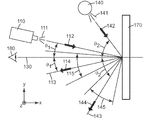
도 1은 일반적으로 3개의 직교축(x, y, z)을 한정하는 프로젝션 시스템(100)의 개략 측면도이다. 프로젝션 시스템(100)은 비대칭 광학 확산기(170), 실질적으로 경면인 반사기(150) 및 광 흡수 층(160)을 포함하는 광 확산 광학 구조물(190), 주변 광원(140) 및 이미지 투사 광원(110)을 포함한다.1 is a schematic side view of a
이미지 투사 광원(110)은 대체로 제1 방향(112)을 따라 이미지 평면(120) 상으로 이미지 광(111)을 투사한다. 제1 방향(112)은 x-축을 따르는 수평 방향(130)과 각도 θ1을 이룬다. 일부 경우에, 각도 θ1은 실질적으로 0도와 같다. 그러한 경우에, 각도 θ1은 약 20도 미만, 또는 약 15도 미만, 또는 약 10도 미만, 또는 약 5도 미만, 또는 약 3도 미만이다.The image
주변 광원(140)은 수평 방향(130)과 각도 θ2를 이루는 대체로 제2 방향(142)을 따라 주변광(141)을 방출한다. 일부 경우에, 각도 θ2는 각도 θ1보다 실질적으로 더 크다. 그러한 경우에, 각도 θ2는 약 20도 이상, 또는 약 30도 이상, 또는 약 40도 이상, 또는 약 50도 이상, 또는 약 60도 이상, 또는 약 70도 이상만큼 각도 θ1보다 더 크다. 일부 경우에, 각도 θ2는 약 40도 초과, 또는 약 50도 초과, 또는 약 60도 초과, 또는 약 70도 초과이다.The
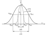
비대칭 광학 확산기(170)는 상이하게 여러 방향을 따라, 예를 들어 x-방향에 평행한 수평 방향(130)을 따라 그리고 y-방향에 평행한 수직 방향(132)을 따라 입사광을 산란시킨다. 도 2는 상호 직교하는 수평 방향 및 수직 방향을 따른 비대칭 광학 확산기(170)의 각각의 수평 및 수직 이득 곡선(210, 220)들의 개략적인 선도이다. 비대칭 광학 확산기(170)는 축상(on-axis) 또는 0도 시야각에 대응하는 최대 이득 go, 및 AH1 - AH2와 동일한 수평 시야각 AH 및 AV1 - AV2와 동일한 수직 시야각 AV를 한정하는 최대-반값 이득 g1 = go/2을 갖는다. AH1 및 AH2는 양의 수평 시야각 및 음의 수평 시야각으로 각각 지칭될 수 있으며, AV1 및 AV2는 양의 수직 시야각 및 음의 수직 시야각으로 각각 지칭될 수 있다. 도 2의 예시적인 이득 선도에서, 이득 곡선(210, 220)들의 각각은 축상 관찰 방향에 관해 대칭이다. 일반적으로, 이득 곡선(210, 220)들은 축상 관찰 방향에 관해 대칭일 수 있거나 대칭이 아닐 수 있다. 예를 들어, 일부 경우에, 양의 시야각에 관해 절반-휘도 시야각에 대응하는 양의 시야각 AH1은 음의 시야각에 관해 절반-휘도 시야각에 대응하는 음의 시야각 AH2와 상이할 수 있다.Asymmetric
도 1을 다시 참조하면, 광학 확산기(170)는 비대칭 확산기이며, 이는 수평 시야각 AH가 수직 시야각 AV와 상이함을 의미한다. 일부 경우에, 비대칭 광학 확산기(170)는 제1 시야각 AH를 갖는 제1 방향, 예를 들어 수평 방향으로, 그리고 제2 시야각 AV를 갖는, 제1 방향에 직교하는 제2 방향, 예를 들어 수직 방향으로 광을 산란시킨다. 일부 경우에, AH/AV의 비는 약 2 이상, 또는 약 2.2 이상, 또는 약 2.5 이상, 또는 약 2.7 이상, 또는 약 3 이상, 또는 약 3.2 이상, 또는 약 3.5 이상, 또는 약 3.7 이상, 또는 약 4 이상이다. 일부 경우에, 수평 시야각 AH는 약 40도 이상, 또는 약 50도 이상, 또는 약 60도 이상, 또는 약 70도 이상, 또는 약 80도 이상, 또는 약 90도 이상만큼 수직 시야각 AV보다 더 크다.Referring back to FIG. 1, the
비대칭 광학 확산기(170)는 수직 방향(132)을 따라 이미지 평면(120)에 배치된다. 비대칭 확산기(170)는 이미지 광(111)을 수광하고 그 이미지 광을 산란시켜 대체로 제2 방향(114)을 따라 전파되는 산란된 이미지 광(113)을 형성한다. 일부 경우에, 방향(112, 114)들은 x-축에 관해 대칭이다. 그러한 경우에, 제2 방향(114)은 수평 방향(130)과 각도 θ1을 이룬다. 일부 경우에, 산란된 이미지 광(113)은 수평 방향(130)과 각도 αV를 이루는 원하는 관찰 위치(180)를 포함하거나 포괄하는 수직 이미지 광 원추(115)를 갖는다.Asymmetric
비대칭 확산기(170)는 주변광(141)을 수광하고 그 주변광을 산란시켜 대체로 제4 방향(144)을 따라 전파되는 산란된 주변광(143)을 형성한다. 일부 경우에, 방향(142, 144)들은 수평 방향(130)에 관해 대칭이다. 그러한 경우에, 제4 방향(144)은 수평 방향(130)과 각도 θ2를 이룬다. 일부 경우에, 산란된 주변광(143)은 원하는 관찰 위치(180)를 포함하지 않거나 포괄하지 않는 수직 주변광 원추(145)를 갖는다.The
일부 경우에, 관찰 위치(180)는 수직 이미지 광 원추(115) 내에 포함되거나 위치되지만, 수직 주변광 원추(145) 내에는 포함되거나 위치되지 않는다. 그러한 경우에, 관찰 위치(180)의 관찰자는 고콘트라스트를 갖는 이미지를 볼 수 있는데, 그 이유는 그러한 이미지는 주변 광원(140)으로부터 유래하는 주변광을 포함하지 않거나 아주 조금 포함하기 때문이다. 일부 경우에, 비대칭 확산기(170)의 수직 시야각은 수직 이미지 광 원추(115)가 관찰 위치(180)를 포함하거나 포괄할 정도로 충분히 크고, 수직 주변광 원추(145)가 관찰 위치(180)를 포함하지 않을 정도로 충분히 작다.In some cases,
일부 경우에, 예를 들어 각도 αV가 도 3에 개략적으로 도시된 바와 같이 실질적으로 0도와 동일할 때, 비대칭 확산기(170)에 의해 산란된 이미지 광은 관찰 위치(180)에 도달하고, 확산기에 의해 산란된 주변광은 그 관찰 위치로부터 멀리 전파된다. 그러한 경우에, 확산기(170)의 절반 수직 시야각(AV/2)은 θ1보다 크고 θ2보다 작다. 그러한 경우에, 관찰 위치(180)의 관찰자는 향상된 콘트라스트를 갖는 디스플레이된 이미지를 관찰한다.In some cases, for example, when the angle α V is substantially equal to zero degrees as shown schematically in FIG. 3, the image light scattered by the
반사기(150)는 광학 확산기(170)에 의해 산란되지 않은 이미지 광(155)을 반사한다. 일부 경우에, 반사기(150)는 실질적으로 경면 반사기이다. 그러한 경우에, 반사기(150)에 의해 반사되는 전체 광 중 상당한 부분이 경면 반사되고, 전체 반사된 광 중 작은 부분만이 확산 반사된다. 예를 들어, 그러한 경우에, 가시 파장에서 반사기(150)의 전체 반사율에 대한 경면 반사율의 비는 약 0.7 이상, 또는 약 0.75 이상, 또는 약 0.8 이상, 또는 약 0.85 이상, 또는 약 0.9 이상, 또는 약 0.95 이상이며, 여기서 가시 파장은 전자기 스펙트럼의 가시 범위 내의 임의의 파장일 수 있다. 일부 경우에, 가시 범위는 약 400 nm 내지 약 690 nm, 또는 약 410 nm 내지 약 680 nm, 또는 약 420 nm 내지 약 670 nm이다.
반사기(150)는 이미지 광(155)을, 수평 방향과 각도 θ1을 이루는 제5 방향(152)을 따라 반사된 이미지 광(151)으로서 경면 반사한다. 반사기(150)는 광학 확산기(170)에 의해 산란되지 않은 주변광(156)을 반사한다. 반사기(150)는 주변광(156)을, 수평 방향과 각도 θ2를 이루는 제6 방향(154)을 따라 반사된 주변광(153)으로서 경면 반사한다. 일부 경우에, 관찰 위치(180), 이미지 투사 광원(110) 및 주변 광원(140)의 위치들은, 관찰 위치(180)의 관찰자가 반사된 이미지 광(151)을 받아 보지만 반사된 주변광(153)을 받아 보지는 않게 되어 있다. 그러한 경우에, 경면 반사기(150)는 비대칭 광학 확산기(170)에 의해 산란되지 않은 이미지 광(155)을 관찰 위치를 향해 반사하고, 비대칭 광학 확산기(170)에 의해 산란되지 않은 주변광(156)을 관찰 위치로부터 멀리 반사한다. 그러한 경우에, 관찰 위치(180)에 위치한 관찰자는 증가된 콘트라스트를 갖는 이미지를 관찰할 수 있다.The
일부 경우에, 경면 반사기(150)의 반사율은 입사각이 증가함에 따라 변하지 않거나 매우 조금 변한다. 그러한 경우에, 경면 반사기(150)는 약 θ1의 입사각의 가시광에서 제1 평균 반사율 R1, 및 약 θ2의 입사각의 가시광에서 제2 평균 반사율 R2를 가지는데, 여기서 R1과 R2 사이의 차이는 약 10% 이하, 또는 약 5% 이하, 또는 약 2% 이하이다. 일부 경우에, 각도 θ1은 약 0도이고, 각도 θ2는 약 45도이다.In some cases, the reflectance of the
일부 경우에, 경면 반사기(150)의 반사율은 입사각이 증가함에 따라 변하는데, 예를 들어 감소한다. 일부 경우에, 예를 들어 각도 θ1이 각도 θ2보다 실질적으로 작을 때, 입사각이 증가함에 따라 반사율이 감소하는 반사기(150)는 관찰 위치(180)와 같은 관찰 위치로 디스플레이되는 이미지의 콘트라스트를 증가시킬 수 있다. 일부 경우에, 경면 반사기(150)는 약 θ1의 입사각의 가시광에서 제1 평균 반사율 R1, 및 약 θ2의 입사각의 가시광에서 제2 평균 반사율 R2를 가지는데, 여기서 R1/R2의 비는 약 1.2 이상, 또는 약 1.4 이상, 또는 약 1.5 이상, 또는 약 1.6 이상, 또는 약 1.8 이상, 또는 약 2 이상, 또는 약 2.5 이상, 또는 약 3 이상이다. 일부 경우에, 각도 θ1은 약 0도이고, 각도 θ2는 약 45도이다.In some cases, the reflectance of the
일부 경우에, 경면 반사기(150)는 전자기 스펙트럼의 가시 영역과 같은 영역에서 실질적으로 평평한 반사율 스펙트럼을 가질 수 있다. 예를 들어, 그러한 경우에, 경면 반사기의 반사율은 가시광에서 20% 이하만큼, 또는 15% 이하만큼, 또는 10% 이하만큼, 또는 5% 이하만큼 변한다. 일부 경우에, 청색 파장, 예를 들어 440 nm에서의 반사기(150)의 반사율과 적색 파장, 예를 들어 620 nm에서의 반사율의 비는 약 0.8 내지 약 1.2의 범위, 또는 약 0.9 내지 약 1.1의 범위 내이다.In some cases, the
일반적으로, 경면 반사기(150)는 소정 응용에 바람직하고 그리고/또는 실용적일 수 있는 임의의 경면 반사기일 수 있다. 예를 들어, 경면 반사기(150)는 알루미늄 도금 필름 또는 다층 중합체성 반사 필름, 예를 들어 반사 편광 필름 또는 미국 미네소타주 세인트 폴 소재의 쓰리엠 컴퍼니(3M Company)로부터 입수가능한 비퀴티(Vikuiti) ESR 필름일 수 있다.In general, the
광 흡수 층(160)은 경면 반사기(150)에 의해 반사되지 않은 이미지 광(161) 및 주변광(162)을 흡수함으로써 디스플레이되는 이미지의 콘트라스트를 증가시킬 수 있다. 광 흡수 층(160)은 소정 응용에 바람직하고 그리고/또는 실용적일 수 있는 임의의 광 흡수 재료를 포함할 수 있다. 예를 들어, 층(160)은 카본 블랙, 흑색 염료 또는 다른 어두운 색의 염료와 같은 광 흡수성 염료, 광 흡수성 안료 또는 다른 어두운 색의 안료, 또는 불투명 입자 - 결합제 재료에 분산됨 - 를 포함할 수 있다. 적합한 결합제는 열가소성 물질, 방사선 경화성 또는 열경화성 아크릴레이트, 에폭시, 실리콘계 재료, 또는 다른 적합한 결합제 재료를 포함한다. 일부 경우에, 가시광에서의 광 흡수 층(160)의 광학 흡수 계수는 약 0.1 마이크로미터-1 이상, 또는 약 0.2 마이크로미터-1 이상, 또는 약 0.4 마이크로미터-1 이상, 또는 약 0.6 마이크로미터-1 이상이다.The light
일부 경우에, 광학 구조물(190)은 선택적인 기재(185)를 포함한다. 일부 경우에, 기재(185)는 광학 구조물 내의 다른 구성요소에 지지를 주로 제공할 수 있다. 일부 경우에, 기재(185)는 하나 이상의 추가적인 광학 기능을 제공할 수 있다. 예를 들어, 기재(185)는 광학 확산기, 광대역 광 흡수기, 흡수 편광기, 반사 편광기, 또는 소정 응용에 바람직할 수 있는 기능을 갖는 임의의 다른 필름일 수 있거나 이들을 포함할 수 있다. 기재(185)는 소정 응용에 적합한 그리고/또는 실용적일 수 있는 임의의 재료, 예를 들어 폴리에틸렌 테레프탈레이트(PET), 폴리비닐클로라이드(PVC), 폴리카르보네이트, 아크릴, 알루미늄 시트, 유리, 및 이들의 복합물일 수 있다.In some cases,
일반적으로, 광학 구조물(190)은 광을 비대칭적으로 산란시키는 것이 바람직할 수 있는 임의의 응용에 채용될 수 있다. 예를 들어, 광학 구조물(190)은 전방 프로젝션 스크린이거나 그 일부일 수 있다.In general, the
이미지 투사 광원(110)은 이미지 형성 장치를 포함하며, 이 장치에 의해 형성된 이미지를 디스플레이 또는 이미지 평면(120) 상으로 투사한다. 프로젝터(110)의 출력 광(111)은 소정 응용에 바람직할 수 있는 임의의 편광을 가질 수 있다. 예를 들어, 일부 경우에, 출력 광(111)은 실질적으로 비편광된다. 그러한 경우에, 제1 편광 상태를 갖는 출력 광(111)의 세기(intensity)와 제1 편광 상태에 수직한 제2 편광 상태를 갖는 출력 광의 세기의 비는 약 0.8 내지 약 1.2, 또는 약 0.85 내지 약 1.15, 또는 약 0.9 내지 약 1.1, 또는 약 0.95 내지 약 1.05의 범위 내이다. 일부 경우에, 출력 광(111)은 예를 들어 제1 방향을 따라 실질적으로 편광된다. 그러한 경우에, 제1 편광 상태를 갖는 출력 광(111)의 세기 대 직교하는 편광 상태를 갖는 출력 광의 세기의 비는 약 100 이상, 또는 약 500 이상, 또는 약 1000 이상이다. 일부 경우에, 출력 광(110)은 편광 상태들의 혼합을 포함한다. 예를 들어, 일부 경우에, 출력 광(110)은 적색, 녹색 및 청색 광을 포함할 수 있으며, 여기서 청색 광 및 적색 광은 하나의 편광 상태를 가지며 녹색 광은 직교하는 편광 상태를 갖는다.The image projection
일반적으로, 이미지 투사 광원(110)은 임의의 이미지 형성 장치를 포함할 수 있다. 예를 들어, 이미지 형성 장치는 반사형 디스플레이, 투과형 디스플레이, 또는 발광형 디스플레이(emissive display), 또는 반투과형 디스플레이(transflective display)와 같은 여러 디스플레이 유형들의 조합일 수 있다. 예를 들어, 일부 경우에, 반사형 이미지 형성 장치는 LCD 또는 디지털 마이크로-미러 어레이 디스플레이(digital micro-mirror array display), 예를 들어 텍사스 인스트루먼츠, 인크.(Texas Instruments, Inc.)의 디지털 라이트 프로세서(Digital Light Processor, DLP)를 포함할 수 있다.In general, image projection
일반적으로, 비대칭 광학 확산기(170)는 소정 응용에서 바람직하고 그리고/또는 실용적일 수 있는 임의의 비대칭 확산기일 수 있다. 예를 들어, 비대칭 확산기(170)는 벌크 확산기(bulk diffuser) 및/또는 표면 확산기일 수 있다. 벌크 확산은 예를 들어 호스트 재료(host material)에 게스트 재료(guest material)의 작은 입자를 포함시키거나 분산시킴으로써 달성될 수 있는데, 여기서 게스트 재료 및 호스트 재료는 상이한 굴절률을 갖는다. 표면 확산은 예를 들어 확산기의 표면을 무광택(matte)으로 만듦으로써 달성될 수 있다. 일부 경우에, 확산기(170)는 벌크 확산기이며, 게스트 재료와 호스트 재료의 굴절률들 사이의 차이는 약 0.01 이상, 또는 약 0.02 이상, 또는 약 0.03 이상, 또는 약 0.04 이상이다.In general, asymmetric
일부 경우에, 비대칭 광학 확산기(170)는 실질적으로 편광-무의존성(polarization-insensitive)일 수 있다. 그러한 경우에, 주어진 방향, 예를 들어 수평 방향을 따른 상호 직교 편광된 2개의 입사광에 관한 비대칭 광학 확산기의, 수평 이득 곡선(210)들과 같은 이득 곡선들은 실질적으로 동일하다. 예를 들어, 그러한 경우에, 수평 방향을 따른 상호 직교 편광된 2개의 입사광에 관한 수평 이득 곡선(210)들은 약 15% 이하만큼, 또는 약 10% 이하만큼, 또는 약 5% 이하만큼 차이가 있다. 다른 예로서, 수직 방향을 따른 상호 직교 편광된 2개의 입사광에 관한 수직 이득 곡선(220)들은 약 15% 이하만큼, 또는 약 10% 이하만큼, 또는 약 5% 이하만큼 차이가 있다.In some cases, asymmetric
일부 경우에, 비대칭 광학 확산기(170)는 구조화된 표면 또는 층을 포함할 수 있다. 구조화된 층은 소정 응용에 바람직할 수 있는 임의의 형상을 갖는 구조체를 포함할 수 있다. 예시적인 형상에는 평탄한 형상, 오목한 형상, 볼록한 형상, 비구면 형상, 프레넬(Fresnel) 형상, 타원체 형상, 피브릴(fibril) 형상, 회절 형상, 및 다면형(faceted) 형상이 포함된다. 예를 들어, 도 4는 피치(430)를 갖는 마이크로렌즈(420)들과 같은 복수의 광학 렌즈를 포함하는 구조화된 표면(410)을 포함하는 비대칭 광학 확산기(470)의 개략 측면도이다. 일부 경우에, 광학 렌즈들 중 적어도 일부는 예를 들어 이미지 투사 광원(110)에 의해 투사되는 이미지의 종횡비를 변경하기 위해 왜상형(anamorphic)일 수 있다. 일부 경우에, 왜상형 렌즈는 원통형과 같이 긴 렌즈일 수 있거나 이를 포함할 수 있다. 일부 경우에, 비대칭 광학 확산기(170)는 랜덤 피치(random pitch)(430)를 갖는 원통형 렌즈들의 어레이(array)와 같은 긴 광학 렌즈들의 어레이를 포함할 수 있다. 도 6은 복수의 렌즈릿(lenslet)(620)을 포함하는, 구조화된 표면(410)과 유사한 구조화된 표면(610)의 개략 평면도이다. 각각의 렌즈릿은 폭 a1, 길이 a2, 및 종횡비 a2/a1를 갖는다. 일부 경우에, 종횡비는 약 1.5 내지 약 200, 또는 약 2 내지 약 100, 또는 약 2 내지 약 50, 또는 약 2 내지 약 25의 범위 내이다.In some cases, asymmetric
일부 경우에, 비대칭 광학 확산기(170)는 벌크 확산기이고, 제2 재료 내에 있는 제1 재료로 된 복수의 긴 구조체 또는 입자를 포함하며, 여기서 두 재료는 상이한 굴절률을 갖는다. 일부 경우에, 긴 입자는 일반적으로 동일한 방향을 따라, 예를 들어 수직 방향(132)을 따라 배향된다. 일부 경우에, 긴 입자의 길이는 약 50 nm 내지 약 100 마이크로미터, 또는 약 100 nm 내지 약 50 마이크로미터, 또는 약 200 nm 내지 약 10 마이크로미터의 범위 내이다. 일부 경우에, 긴 입자의 종횡비는 약 5:1 내지 약 1000:1, 또는 약 10:1 내지 약 200:1, 또는 약 20:1 내지 약 50:1의 범위 내이다.In some cases, asymmetric
일부 경우에, 광학 구조물(190)은 통합된 구조물이며, 이는 그 구조물 내의 개개의 구성요소들이 예를 들어 하나 이상의 접착제 층에 의해 서로 부착됨을 의미한다.In some cases,
개시된 시스템 및 구조물들의 이점들 중 일부가 하기의 실시예에 의해 추가로 예시된다. 이 실시예에서 언급되는 구체적인 재료, 양 및 치수뿐만 아니라 다른 조건 및 상세 사항은 본 발명을 부당하게 제한하는 것으로 해석되어서는 안 된다.Some of the advantages of the disclosed systems and structures are further illustrated by the following examples. The specific materials, amounts, and dimensions as well as other conditions and details mentioned in this example should not be construed as unduly limiting the invention.
실시예Example 1 One
확산기(170)와 유사한 비대칭 광학 확산기를 제조하였다. 폴리프로필렌(PP)의 펠릿(미국 텍사스주 휴스턴 소재의 엑손 케미칼스(Exxon Chemicals)로부터 입수가능한 PP1024)과 (80℃(176℉)에서 10시간 동안) 오븐 건조한 폴리스티렌(PS)(미국 미시간주 미들랜드 소재의 다우 케미칼(Dow Chemical)로부터 입수가능한 스티론(Styron) 685D)을 약 60/40(PP/PS)의 중량비로 혼합하고 압출기에 넣었다. 이 혼합물을 약 238℃(460℉)의 압출 온도, 약 136 kg/시간(300 lb/시간)의 압출 속도, 및 약 0.254 m/s(50 피트/분)의 선속도로 용융 압출하였다. 압출된 필름 두께는 약 100 마이크로미터였다. 압출 동안에, 용융된 PS 미소 상(minor phase)을 대체로 웨브(web) 또는 압출 방향을 따라 배향된 긴 입자로 신장시켰다. 긴 입자는 평균 직경이 약 1000 나노미터이고 평균 종횡비가 약 100인 로드(rod) 형상이었다. 긴 PS 입자의 굴절률은 1.58이었다. PP 호스트의 굴절률은 1.50이었다.An asymmetric optical diffuser similar to
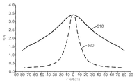
그 다음에, 압출된 필름을 미국 미네소타주 세인트 폴 소재의 쓰리엠 컴퍼니로부터 입수가능한 인핸스드 스펙큘러 리플렉터(enhanced specular reflector, ESR) 필름에 라미네이팅하였다. ESR 필름은 수직 입사에서 약 400 nm 내지 약 1000 nm의 파장 범위에서 반사율이 약 99%였다. ESR의 반사율은 45도의 입사각에서 약 99%로 유지되었다. 라미네이션(lamination)은 미국 미네소타주 세인트 폴 소재의 쓰리엠 컴퍼니로부터 입수가능한, 광학적으로 투명한 접착제 OCA-8171을 사용하여 행하였다. 가시광에서의 생성된 필름의 반사율은 0도의 입사각에서 약 90%였고 약 45도의 입사각에서 약 80%였다. 그 다음에, 동일한 투명 접착제를 사용하여, 생성된 라미네이트를 흑색의 광 흡수 필름(미국 미네소타주 세인트 폴 소재의 쓰리엠 컴퍼니로부터 입수가능한 스카치칼 그래픽 필름(ScotchCal Graphic Film) 7725)에 라미네이팅하였다. 생성된 전방 프로젝션 스크린은 하기의 특성을 가졌다: 약 3.5의 축상 이득, 약 120도의 수평 시야각 AH, 및 25도의 수직 시야각 AV.The extruded film was then laminated to an enhanced specular reflector (ESR) film available from 3M Company, St. Paul, Minn., USA. The ESR film had a reflectance of about 99% in the wavelength range of about 400 nm to about 1000 nm at normal incidence. The reflectivity of the ESR was maintained at about 99% at an incidence angle of 45 degrees. Lamination was done using an optically clear adhesive OCA-8171, available from 3M Company, St. Paul, Minn., USA. The reflectance of the resulting film in visible light was about 90% at an angle of incidence of 0 degrees and about 80% at an angle of incidence of about 45 degrees. The resulting laminate was then laminated to a black light absorbing film (ScotchCal Graphic Film 7725 available from 3M Company, St. Paul, Minn.) Using the same transparent adhesive. The resulting front projection screen had the following characteristics: axial gain of about 3.5, horizontal viewing angle A H of about 120 degrees, and vertical viewing angle A V of 25 degrees.
몇몇 상이한 입사각 θ로 스크린에 입사하는 광에 대해 스크린의 반사율 RRθ를 스크린에 수직하게 측정하였다. RR45/RRo(45도 및 0도의 수평 입사각)의 비는 약 0.66이었다. 램버시안(lambertian) 확산기의 경우에 유사한 비는 약 0.82였으며, 이는 램버시안 확산기와 비교하여 스크린이 약 19%의 개선된 주변광 거부(ambient light rejection)를 가졌음을 나타낸다. 스크린은 60도의 수평 입사각에 관해서 약 27%의 개선된 주변광 거부를 가졌다. 스크린은 45도의 수직 입사각에 관해서 약 72%의 개선된 주변광 거부를 가졌다. RRθ 측정은 500 룩스 주변광의 존재 하에서 수행하였다. 수평 편광된 입사광과 수직 편광된 입사광 사이의 스크린의 반사율의 평균 차이는 약 5% 미만이었다.The reflectance RR θ of the screen was measured perpendicular to the screen for light incident on the screen at several different incident angles θ. The ratio of RR 45 / RR o (horizontal angle of incidence of 45 degrees and 0 degrees) was about 0.66. The similar ratio for the Lambertian diffuser was about 0.82, indicating that the screen had about 19% improved ambient light rejection compared to the Lambertian diffuser. The screen had about 27% improved ambient light rejection with respect to the horizontal angle of incidence of 60 degrees. The screen had an improved ambient light rejection of about 72% with respect to the vertical angle of incidence of 45 degrees. RR θ measurements were performed in the presence of 500 lux ambient light. The average difference in the reflectance of the screen between the horizontally polarized incident light and the vertically polarized incident light was less than about 5%.
도 5는 측정된 수평 이득 곡선(510) 및 수직 이득 곡선(520)을 도시한다.5 shows the measured
실시예 2Example 2
리플렉터 필름이 미국 미네소타주 세인트 폴 소재의 쓰리엠 컴퍼니로부터 입수가능한 협대역 스펙큘러 리플렉터(narrow-band specular reflector, c-ESR) 필름인 것을 제외하고, 실시예 1의 구조물과 유사한 광학 구조물을 제조하였다. c-ESR 필름은 수직 입사에서 약 400 nm 내지 약 700 nm의 파장 범위에서 반사율이 약 99%였다. 0도의 입사각의 가시광에서의 c-ESR 필름의 평균 반사율 대 45도의 입사각의 가시광에서의 c-ESR 필름의 평균 반사율의 비는 약 1.7이었다. 생성된 전방 프로젝션 스크린은 하기의 특성을 가졌다: 약 3.5의 축상 이득, 약 120도의 수평 시야각 AH, 및 약 25도의 수직 시야각 AV.An optical structure similar to that of Example 1 was prepared except that the reflector film was a narrow-band specular reflector (c-ESR) film available from 3M Company, St. Paul, Minn. The c-ESR film had a reflectance of about 99% in the wavelength range of about 400 nm to about 700 nm at normal incidence. The ratio of the average reflectance of the c-ESR film in visible light at an incident angle of 0 degrees to the average reflectance of the c-ESR film in visible light at an incident angle of 45 degrees was about 1.7. The resulting front projection screen had the following characteristics: axial gain of about 3.5, horizontal viewing angle A H of about 120 degrees, and vertical viewing angle A V of about 25 degrees.
RR45/RRo(45도 및 0도의 수평 입사각)의 비는 약 0.62였다. 램버시안 확산기의 경우에 유사한 비는 약 0.82였으며, 이는 램버시안 확산기와 비교하여 스크린이 약 24%의 개선된 주변광 거부를 가졌음을 나타낸다. 스크린은 60도의 수평 입사각에 관해 약 31%의 개선된 주변광 거부를 가졌다. 스크린은 45도의 수직 입사각에 관해 약 79% 그리고 약 60도의 수직 입사각에 관해 약 84%의 개선된 주변광 거부를 가졌다. RRθ 측정은 500 룩스 주변광의 존재 하에서 수행하였다. 수평 편광된 입사광과 수직 편광된 입사광 사이의 스크린의 반사율의 평균 차이는 약 5% 미만이었다.The ratio of RR 45 / RR o (horizontal angle of incidence of 45 degrees and 0 degrees) was about 0.62. A similar ratio for the Lambertian diffuser was about 0.82, indicating that the screen had about 24% improved ambient light rejection compared to the Lambertian diffuser. The screen had an improved ambient light rejection of about 31% for a horizontal angle of incidence of 60 degrees. The screen had improved ambient light rejection of about 79% for a vertical angle of incidence of 45 degrees and about 84% for a vertical angle of incidence of about 60 degrees. RR θ measurements were performed in the presence of 500 lux ambient light. The average difference in the reflectance of the screen between the horizontally polarized incident light and the vertically polarized incident light was less than about 5%.
본 명세서에 사용되는 바와 같이, "수직", "수평", "위", "아래", "좌측", "우측", "상부" 및 "하부", "전방" 및 "후방", "시계방향" 및 "반시계방향" 및 다른 유사한 용어와 같은 용어들은 도면에 도시된 바와 같은 상대적인 위치를 지칭한다. 일반적으로, 물리적인 실시 형태는 상이한 배향을 가질 수 있으며, 그 경우에 이 용어들은 장치의 실제 배향에 맞추어 수정되는 상대적인 위치를 지칭하도록 의도된다. 예를 들어, 도 1의 구조물이 도면의 배향과 비교하여 90도만큼 회전될지라도, 화살표 방향(130)은 여전히 "수평" 방향을 따르는 것으로 간주된다.As used herein, "vertical", "horizontal", "up", "down", "left", "right", "top" and "bottom", "front" and "rear", "clock" Terms such as "direction" and "counterclockwise" and other similar terms refer to relative positions as shown in the figures. In general, physical embodiments may have different orientations, in which case these terms are intended to refer to relative positions that are modified to the actual orientation of the device. For example, even though the structure of FIG. 1 is rotated by 90 degrees relative to the orientation of the figure, the
이상에서 언급된 모든 특허, 특허 출원 및 다른 공보들은 상세히 재현한 것처럼 본 문헌에 참고로 포함된다. 본 발명의 특정의 실시예가 본 발명의 다양한 태양의 설명을 용이하게 하기 위해 위에서 상세히 기술되었지만, 본 발명을 실시예의 상세 사항으로 제한하고자 하는 것이 아님을 알아야 한다. 오히려, 본 발명은 첨부된 특허청구범위에 의해 한정되는 본 발명의 사상 및 범주 내에 속하는 모든 수정, 실시 형태 및 대안을 포함하고자 한다.All patents, patent applications, and other publications mentioned above are incorporated herein by reference as if reproduced in detail. While certain embodiments of the invention have been described in detail above to facilitate describing various aspects of the invention, it should be understood that they are not intended to limit the invention to the details of the embodiments. Rather, the invention is intended to embrace all modifications, embodiments, and alternatives falling within the spirit and scope of the invention as defined by the appended claims.
Claims (24)
비대칭 광학 확산기에 의해 산란되지 않은 광을 반사하며, 실질적으로 0도의 입사각의 가시광에서 제1 평균 반사율 Ro, 및 실질적으로 45도의 입사각의 가시광에서 제2 평균 반사율 R45를 갖는 실질적으로 경면인 반사기 - Ro/R45는 약 1.5 이상임 - ; 및
경면 반사기에 의해 반사되지 않은 광을 흡수하는 광 흡수 층을 포함하는 광 확산 광학 구조물.An asymmetric optical diffuser that scatters light in a first direction having a first viewing angle A H and in a second direction orthogonal to the first direction having a second viewing angle A V , wherein A H / A V is at least about 2;
A substantially specular reflector that reflects light that is not scattered by the asymmetric optical diffuser and has a first average reflectivity R o at visible light at an angle of incidence of substantially 0 degrees, and a second average reflectance R 45 at visible light at an angle of incidence of 45 degrees. -R o / R 45 is at least about 1.5-; And
A light diffusing optical structure comprising a light absorbing layer that absorbs light that is not reflected by the specular reflector.
디스플레이 평면에 위치된 제1항의 광 확산 광학 구조물을 포함하는 프로젝션 시스템.An image forming apparatus for projecting an image onto the display plane; And
A projection system comprising the light diffusing optical structure of claim 1 positioned in a display plane.
수평 방향과 각도 θ2를 이루는 대체로 제2 방향을 따라 주변광을 방출하는 주변 광원;
이미지 평면에 배치되며, 수평 방향을 따라 제1 시야각 AH 및 수평 방향에 직교하는 수직 방향을 따라 제2 시야각 AV를 갖는 비대칭 광학 확산기 - AH/AV는 약 2 이상이며, AV/2는 θ1보다 크고 θ2보다 작음 - ; 및
비대칭 광학 확산기에 의해 산란되지 않은 광을 반사하며, 약 θ1의 입사각의 가시광에서 제1 평균 반사율 R1, 및 약 θ2의 입사각의 가시광에서 제2 평균 반사율 R2를 갖는 실질적으로 경면인 반사기 - R1/R2은 약 1.5 이상임 - 를 포함하는 프로젝션 시스템.An image projection light source that projects image light onto the image plane generally along the first direction, the first direction being at an angle θ 1 with the horizontal direction;
An ambient light source emitting ambient light along a second direction, the angle θ 2 being in a horizontal direction;
Asymmetric optical diffuser disposed in the image plane and having a first viewing angle A H along the horizontal direction and a second viewing angle A V along the vertical direction orthogonal to the horizontal direction-A H / A V is at least about 2, and A V / 2 is greater than θ 1 and less than θ 2- ; And
And reflecting the non-scattered light by asymmetric optical diffuser, in the visible light of an incident angle of approximately θ 1 first average reflectivity R 1, and a substantially mirror surface of the reflector in the visible light of the incident angle of about θ 2 has a second average reflectivity R 2 A projection system comprising: R 1 / R 2 is at least about 1.5.
Applications Claiming Priority (2)
| Application Number | Priority Date | Filing Date | Title |
|---|---|---|---|
| US14327509P | 2009-01-08 | 2009-01-08 | |
| US61/143,275 | 2009-01-08 |
Publications (1)
| Publication Number | Publication Date |
|---|---|
| KR20110112406A true KR20110112406A (en) | 2011-10-12 |
Family
ID=42111758
Family Applications (1)
| Application Number | Title | Priority Date | Filing Date |
|---|---|---|---|
| KR1020117018204A KR20110112406A (en) | 2009-01-08 | 2010-01-06 | Front projection screen with high contrast |
Country Status (6)
| Country | Link |
|---|---|
| US (1) | US20120013851A1 (en) |
| EP (1) | EP2386073A1 (en) |
| JP (1) | JP2012514771A (en) |
| KR (1) | KR20110112406A (en) |
| CN (1) | CN102341752A (en) |
| WO (1) | WO2010080775A1 (en) |
Cited By (1)
| Publication number | Priority date | Publication date | Assignee | Title |
|---|---|---|---|---|
| EP2845899A1 (en) | 2013-08-02 | 2015-03-11 | Daegu Gyeongbuk Institute of Science and Technology | Dopaminergic neuron-like cell cluster and method for preparing the same |
Families Citing this family (8)
| Publication number | Priority date | Publication date | Assignee | Title |
|---|---|---|---|---|
| EP2385904A1 (en) | 2009-01-08 | 2011-11-16 | 3M Innovative Properties Company | Dry erasable projection article and system |
| CN102667618B (en) | 2009-11-23 | 2015-02-25 | 3M创新有限公司 | Front projection screen with high contrast |
| JP5948991B2 (en) * | 2012-03-13 | 2016-07-06 | 富士ゼロックス株式会社 | Fixing apparatus and image forming apparatus |
| FR2991786B1 (en) | 2012-06-08 | 2014-06-20 | Saint Gobain | PROJECTION SCREEN OPERATING IN REFLECTION INCLUDING VARIABLE LUMINOUS DIFFUSION SYSTEM |
| US10003777B2 (en) * | 2013-11-21 | 2018-06-19 | Hewlett-Packard Development Company, L.P. | Projection screen for specularly reflecting light |
| KR101777532B1 (en) * | 2013-12-27 | 2017-09-11 | 코니카 미놀타 가부시키가이샤 | Optical film, polarizing plate and image display device |
| CN104834127B (en) * | 2015-05-29 | 2018-03-06 | 京东方科技集团股份有限公司 | A kind of display panel and projection display equipment |
| US10288780B2 (en) * | 2015-12-02 | 2019-05-14 | Jxtg Nippon Oil & Energy Corporation | Reflective transparent screen and image projection device comprising same |
Family Cites Families (14)
| Publication number | Priority date | Publication date | Assignee | Title |
|---|---|---|---|---|
| JPH06258717A (en) * | 1993-03-08 | 1994-09-16 | Dainippon Printing Co Ltd | Reflection type projection screen |
| US6381068B1 (en) * | 1999-03-19 | 2002-04-30 | 3M Innovative Properties Company | Reflective projection screen and projection system |
| US6819486B2 (en) * | 2001-01-17 | 2004-11-16 | 3M Innovative Properties Company | Projection screen having elongated structures |
| US6847483B2 (en) * | 2001-12-21 | 2005-01-25 | Bose Corporation | Selective reflecting |
| US6769774B2 (en) * | 2002-11-14 | 2004-08-03 | International Business Machines Corporation | Ambient light tolerant image projection method and system |
| JP4285259B2 (en) * | 2004-01-30 | 2009-06-24 | 凸版印刷株式会社 | Reflective screen |
| US7110175B2 (en) * | 2004-02-27 | 2006-09-19 | Bose Corporation | Display screens |
| JP4706290B2 (en) * | 2004-03-18 | 2011-06-22 | ソニー株式会社 | Screen and manufacturing method thereof |
| JP2005266264A (en) * | 2004-03-18 | 2005-09-29 | Sony Corp | Screen |
| US7408709B2 (en) * | 2004-03-18 | 2008-08-05 | Sony Corporation | Screen and method for manufacturing the same |
| JP4749011B2 (en) * | 2004-04-09 | 2011-08-17 | 直史 山内 | Screen and image projection system using the same |
| JP4244889B2 (en) * | 2004-09-01 | 2009-03-25 | ソニー株式会社 | LIGHT DIFFUSION FILM FOR REFLECTIVE SCREEN, METHOD FOR PRODUCING THE SAME, SCREEN FOR REFLECTIVE SCREEN |
| US7835078B2 (en) * | 2005-02-02 | 2010-11-16 | Dai Nippon Printing Co., Ltd. | Reflecting screen, method of manufacturing the same, and reflection-type projection system |
| JP5064709B2 (en) * | 2006-03-30 | 2012-10-31 | 株式会社きもと | Reflective screen for bright room |
-
2010
- 2010-01-06 CN CN2010800102344A patent/CN102341752A/en active Pending
- 2010-01-06 WO PCT/US2010/020176 patent/WO2010080775A1/en active Application Filing
- 2010-01-06 US US13/143,211 patent/US20120013851A1/en not_active Abandoned
- 2010-01-06 KR KR1020117018204A patent/KR20110112406A/en not_active Application Discontinuation
- 2010-01-06 EP EP10700036A patent/EP2386073A1/en not_active Withdrawn
- 2010-01-06 JP JP2011545396A patent/JP2012514771A/en active Pending
Cited By (1)
| Publication number | Priority date | Publication date | Assignee | Title |
|---|---|---|---|---|
| EP2845899A1 (en) | 2013-08-02 | 2015-03-11 | Daegu Gyeongbuk Institute of Science and Technology | Dopaminergic neuron-like cell cluster and method for preparing the same |
Also Published As
| Publication number | Publication date |
|---|---|
| EP2386073A1 (en) | 2011-11-16 |
| CN102341752A (en) | 2012-02-01 |
| WO2010080775A1 (en) | 2010-07-15 |
| JP2012514771A (en) | 2012-06-28 |
| US20120013851A1 (en) | 2012-01-19 |
Similar Documents
| Publication | Publication Date | Title |
|---|---|---|
| KR20110112406A (en) | Front projection screen with high contrast | |
| US8922888B2 (en) | Front projection screen with high contrast | |
| US8177408B1 (en) | Light filtering directional control element and light fixture incorporating the same | |
| US7408707B2 (en) | Multi-region light scattering element | |
| US9030736B2 (en) | Reflection screen and image display system | |
| US6934080B2 (en) | High efficiency viewing screen | |
| US9188721B2 (en) | Optical module and display device | |
| US7453635B2 (en) | Imaging material with improved contrast | |
| US8220932B2 (en) | Dry erasable projection article and system | |
| CN110244508B (en) | Screen and projection system | |
| WO2015046439A1 (en) | Prism sheet, area light source device, image source unit, and liquid crystal display device | |
| CN109388013B (en) | Projection screen and projection system | |
| CN101620337A (en) | Optical element comprising restrained asymmetrical diffuser | |
| JP2017167224A (en) | Space floating video display device | |
| JP2014199375A (en) | Reflective screen and image display system | |
| CN109388014B (en) | Projection screen and projection system | |
| JP2002006400A (en) | Transmission type screen | |
| JP2015180952A (en) | Prism sheet, surface light source device, video source unit, and liquid crystal display device | |
| US11635562B2 (en) | Image source unit, and liquid crystal display device | |
| JPH09211729A (en) | Reflection type screen | |
| CN203688832U (en) | Optical thin film | |
| JP5949356B2 (en) | Reflective screen, 3D image display system | |
| JP2017198974A (en) | Optical unit, surface light source device, video source unit, and liquid crystal display | |
| JP2006106393A (en) | Light diffusion sheet and projection screen | |
| JP6083301B2 (en) | Video source unit, liquid crystal display device |
Legal Events
| Date | Code | Title | Description |
|---|---|---|---|
| WITN | Application deemed withdrawn, e.g. because no request for examination was filed or no examination fee was paid |