KR20110105359A - Image processing apparatus, image processing method and computer-readable storage medium - Google Patents
Image processing apparatus, image processing method and computer-readable storage medium Download PDFInfo
- Publication number
- KR20110105359A KR20110105359A KR1020110024051A KR20110024051A KR20110105359A KR 20110105359 A KR20110105359 A KR 20110105359A KR 1020110024051 A KR1020110024051 A KR 1020110024051A KR 20110024051 A KR20110024051 A KR 20110024051A KR 20110105359 A KR20110105359 A KR 20110105359A
- Authority
- KR
- South Korea
- Prior art keywords
- image
- template
- pattern
- amount
- unsharpness
- Prior art date
Links
- 238000012545 processing Methods 0.000 title claims abstract description 153
- 238000003860 storage Methods 0.000 title claims abstract description 24
- 238000003672 processing method Methods 0.000 title claims description 8
- 238000001514 detection method Methods 0.000 claims abstract description 137
- 238000000034 method Methods 0.000 claims description 37
- 238000004590 computer program Methods 0.000 claims description 14
- 239000003550 marker Substances 0.000 description 51
- 230000006870 function Effects 0.000 description 29
- 238000012937 correction Methods 0.000 description 28
- 230000008569 process Effects 0.000 description 26
- 238000012360 testing method Methods 0.000 description 13
- 238000006243 chemical reaction Methods 0.000 description 11
- 238000010586 diagram Methods 0.000 description 11
- 238000009826 distribution Methods 0.000 description 9
- 230000008859 change Effects 0.000 description 7
- 238000004891 communication Methods 0.000 description 7
- 238000001228 spectrum Methods 0.000 description 7
- 238000004364 calculation method Methods 0.000 description 5
- 239000006185 dispersion Substances 0.000 description 3
- 238000005315 distribution function Methods 0.000 description 3
- 238000000605 extraction Methods 0.000 description 2
- 230000004048 modification Effects 0.000 description 2
- 238000012986 modification Methods 0.000 description 2
- 230000003287 optical effect Effects 0.000 description 2
- PXFBZOLANLWPMH-UHFFFAOYSA-N 16-Epiaffinine Natural products C1C(C2=CC=CC=C2N2)=C2C(=O)CC2C(=CC)CN(C)C1C2CO PXFBZOLANLWPMH-UHFFFAOYSA-N 0.000 description 1
- 239000003086 colorant Substances 0.000 description 1
- 230000007423 decrease Effects 0.000 description 1
- 238000005516 engineering process Methods 0.000 description 1
- 239000000284 extract Substances 0.000 description 1
- 238000003702 image correction Methods 0.000 description 1
- 238000004519 manufacturing process Methods 0.000 description 1
- 238000000059 patterning Methods 0.000 description 1
- 230000002093 peripheral effect Effects 0.000 description 1
- 238000007639 printing Methods 0.000 description 1
- 230000009467 reduction Effects 0.000 description 1
- 239000004065 semiconductor Substances 0.000 description 1
- 238000006467 substitution reaction Methods 0.000 description 1
- 230000009466 transformation Effects 0.000 description 1
- 230000001131 transforming effect Effects 0.000 description 1
Images


Classifications
-
- G—PHYSICS
- G06—COMPUTING; CALCULATING OR COUNTING
- G06T—IMAGE DATA PROCESSING OR GENERATION, IN GENERAL
- G06T7/00—Image analysis
- G06T7/0002—Inspection of images, e.g. flaw detection
-
- G—PHYSICS
- G06—COMPUTING; CALCULATING OR COUNTING
- G06T—IMAGE DATA PROCESSING OR GENERATION, IN GENERAL
- G06T7/00—Image analysis
-
- G—PHYSICS
- G01—MEASURING; TESTING
- G01B—MEASURING LENGTH, THICKNESS OR SIMILAR LINEAR DIMENSIONS; MEASURING ANGLES; MEASURING AREAS; MEASURING IRREGULARITIES OF SURFACES OR CONTOURS
- G01B11/00—Measuring arrangements characterised by the use of optical techniques
-
- G—PHYSICS
- G06—COMPUTING; CALCULATING OR COUNTING
- G06T—IMAGE DATA PROCESSING OR GENERATION, IN GENERAL
- G06T1/00—General purpose image data processing
-
- G—PHYSICS
- G06—COMPUTING; CALCULATING OR COUNTING
- G06T—IMAGE DATA PROCESSING OR GENERATION, IN GENERAL
- G06T5/00—Image enhancement or restoration
- G06T5/10—Image enhancement or restoration using non-spatial domain filtering
-
- G—PHYSICS
- G06—COMPUTING; CALCULATING OR COUNTING
- G06T—IMAGE DATA PROCESSING OR GENERATION, IN GENERAL
- G06T5/00—Image enhancement or restoration
- G06T5/73—Deblurring; Sharpening
-
- H—ELECTRICITY
- H04—ELECTRIC COMMUNICATION TECHNIQUE
- H04N—PICTORIAL COMMUNICATION, e.g. TELEVISION
- H04N1/00—Scanning, transmission or reproduction of documents or the like, e.g. facsimile transmission; Details thereof
- H04N1/44—Secrecy systems
-
- G—PHYSICS
- G06—COMPUTING; CALCULATING OR COUNTING
- G06T—IMAGE DATA PROCESSING OR GENERATION, IN GENERAL
- G06T2207/00—Indexing scheme for image analysis or image enhancement
- G06T2207/20—Special algorithmic details
- G06T2207/20048—Transform domain processing
- G06T2207/20056—Discrete and fast Fourier transform, [DFT, FFT]
-
- G—PHYSICS
- G06—COMPUTING; CALCULATING OR COUNTING
- G06T—IMAGE DATA PROCESSING OR GENERATION, IN GENERAL
- G06T2207/00—Indexing scheme for image analysis or image enhancement
- G06T2207/20—Special algorithmic details
- G06T2207/20172—Image enhancement details
- G06T2207/20192—Edge enhancement; Edge preservation
-
- G—PHYSICS
- G06—COMPUTING; CALCULATING OR COUNTING
- G06T—IMAGE DATA PROCESSING OR GENERATION, IN GENERAL
- G06T2207/00—Indexing scheme for image analysis or image enhancement
- G06T2207/20—Special algorithmic details
- G06T2207/20172—Image enhancement details
- G06T2207/20201—Motion blur correction
-
- G—PHYSICS
- G06—COMPUTING; CALCULATING OR COUNTING
- G06T—IMAGE DATA PROCESSING OR GENERATION, IN GENERAL
- G06T2207/00—Indexing scheme for image analysis or image enhancement
- G06T2207/30—Subject of image; Context of image processing
- G06T2207/30168—Image quality inspection
Landscapes
- Engineering & Computer Science (AREA)
- Physics & Mathematics (AREA)
- General Physics & Mathematics (AREA)
- Theoretical Computer Science (AREA)
- Computer Vision & Pattern Recognition (AREA)
- Quality & Reliability (AREA)
- Multimedia (AREA)
- Signal Processing (AREA)
- Image Analysis (AREA)
- Image Processing (AREA)
- Studio Devices (AREA)
Abstract
촬영된 화상에 중첩되어 있는 불선명의 양을 검출 가능한 화상 처리 장치를 제공한다. 화상 처리 장치(1)는, 매체에 표시된 화상을 촬영한 판독 화상을 취득하는 인터페이스부(11)와, 매체에 표시된 화상에 포함되는 소정의 패턴에 대하여 서로 다른 불선명량을 중첩한 복수의 템플릿 및 각 템플릿에 중첩된 불선명량을 기억하는 기억부(12)와, 판독 화상에 중첩되어 있는 불선명량을 검출하는 처리부(13)를 갖는다. 처리부(13)는, 판독 화상 상에서 소정의 패턴이 찍혀 있는 패턴 영역을 검지하는 패턴 검출 기능과, 패턴 영역과 복수의 템플릿의 각각과의 일치 정도를 구하고, 그 일치 정도에 기초하여 판독 화상에 찍혀 있는 소정의 패턴과 가장 일치하는 템플릿을 특정하는 매칭 기능과, 그 가장 일치하는 템플릿에 대응하는 불선명량을 판독 화상에 중첩된 불선명량으로 추정하는 판정 기능을 실현한다.An image processing apparatus capable of detecting an amount of unclearness superimposed on a photographed image is provided. The image processing apparatus 1 includes an interface unit 11 for acquiring a read image obtained by photographing an image displayed on a medium, a plurality of templates in which different amounts of unsharpness are superimposed on a predetermined pattern included in the image displayed on the medium; The storage unit 12 stores the amount of unsharpness superimposed on each template, and the processing unit 13 detects the unsharpness superimposed on the read image. The processing unit 13 obtains a pattern detection function for detecting a pattern region in which a predetermined pattern is imprinted on the read image, obtains a degree of correspondence between the pattern region and each of the plurality of templates, and imprints the read image on the basis of the degree of matching. A matching function for specifying a template that most closely matches a predetermined pattern, and a determination function for estimating the amount of unsharpness corresponding to the template that most closely matches the unclear amount superimposed on the read image are realized.
Description
본 발명은, 예를 들면, 매체에 인쇄된 화상을 전자 데이터로 변환한 후에, 그 전자 데이터로 생성된 화상을 처리하는 화상 처리 장치, 화상 처리 방법 및 화상 처리용 컴퓨터 프로그램에 관한 것이다.The present invention relates to, for example, an image processing apparatus, an image processing method, and an image processing computer program for processing an image generated from the electronic data after converting the image printed on the medium into electronic data.
최근, 데이터를 패턴화한 2차원 코드가 널리 이용되고 있다. 이와 같은 2차원 코드에는, 2차원 코드를 판독한 화상으로부터, 2차원 코드의 위치를 결정할 수 있도록, 소정의 패턴을 갖는 위치 결정 심볼이 포함된다(예를 들면, 특허 문헌 1을 참조).In recent years, two-dimensional codes obtained by patterning data have been widely used. Such a two-dimensional code includes a positioning symbol having a predetermined pattern so that the position of the two-dimensional code can be determined from the image from which the two-dimensional code is read (see
또한, 인쇄물에 기재된 비밀 정보가 누설되는 것을 방지하기 위한 기술이 개발되어 있다. 특히, 불특정 다수의 사람에게 보이고 싶지 않은 화상을 미리 암호화하고, 그 암호화된 화상을 종이 등의 매체에 인쇄하는 기술이 제안되어 있다(예를 들면, 특허 문헌 2를 참조). 그와 같은 기술 중의 하나를 이용한 암호화 장치는, 입력 화상 상의 암호화 대상 영역에 포함되는 화소의 배치를, 소정의 암호키에 따라서 블록 단위로 교체한다. 또한 그 암호화 장치는, 암호화된 영역의 4코너 중의 적어도 2개 이상에, 암호화된 영역을 특정하기 위한 위치 결정 마커를 부가한다. 또한 그 암호화 장치는, 암호화된 영역을 복호함으로써 얻어지는 복호 화상의 타당성을 검증하기 위한 체크용 마커를 붙인다. 한편, 복호 장치는, 암호화된 영역을 갖는 화상이 인쇄된 매체를, 스캐너 또는 디지털 카메라 등의 판독 장치를 이용하여 읽어들여 전자 데이터화한다. 그리고 복호 장치는, 전자 데이터화된 화상에 대하여 위치 결정 마커를 참조하여 암호화된 영역을 복호함으로써, 원화상을 얻는다.In addition, techniques have been developed to prevent leakage of confidential information described in printed matter. In particular, a technique has been proposed in which an image which is not desired to be displayed to an unspecified number of people is encrypted in advance and the encrypted image is printed on a medium such as paper (see
그러나, 2차원 코드 또는 암호 화상이 인쇄된 매체가, 디지털 카메라 또는 카메라가 딸린 휴대 전화 등에 의해 촬영되면, 초점 위치 어긋남에 의해 촬영된 화상이 불선명하거나(blurred), 또한 손떨림에 의한 불선명이 그 촬영된 화상에 중첩되게 되는 경우가 있다. 그리고 이와 같은 불선명이 촬영된 화상에 중첩되면, 그 화상에 찍혀 있는 2차원 코드에 포함되는 데이터를 재생할 수 없게 될 우려가 있다. 혹은, 암호 화상을 복호함으로써 얻어진 화상의 화질이 원화상의 화질과 비교하여 대폭 열화되게 된다.However, when a medium on which a two-dimensional code or an encrypted image is printed is photographed by a digital camera or a mobile phone with a camera, the photographed image is blurred due to the shift in focus position, or the blurring caused by camera shake is not achieved. It may be superimposed on a photographed image. If such unclearness is superimposed on the photographed image, there is a fear that data contained in the two-dimensional code captured in the image cannot be reproduced. Alternatively, the image quality of the image obtained by decoding the encrypted image is significantly deteriorated compared with the image quality of the original image.
한편, 촬영된 화상으로부터 구한 엣지 강도 또는 자기 상관값에 기초하여, 그 화상에 중첩된 불선명 또는 손떨림량을 평가하는 기술이 제안되어 있다(예를 들면, 특허 문헌 3 및 4를 참조).On the other hand, based on the edge intensity or the autocorrelation value calculated | required from the image | photographed image, the technique of evaluating the unsharpness or the amount of shaking superimposed on the image is proposed (for example, refer
그러나, 화상 상의 엣지 강도 또는 자기 상관값은, 촬영 대상으로 된, 매체에 인쇄되어 있는 화상에도 의존한다. 그 때문에, 매체에 인쇄되어 있는 화상에 상관없이, 촬영된 화상에 중첩되어 있는 불선명의 양을 검출 가능한 기술이 요구되고 있다.However, the edge intensity or autocorrelation value on the image also depends on the image printed on the medium to be photographed. Therefore, there is a demand for a technique capable of detecting the amount of unclearness superimposed on the photographed image irrespective of the image printed on the medium.
따라서, 본 명세서는, 촬영된 화상에 중첩되어 있는 불선명의 양을 검출 가능한 화상 처리 장치, 화상 처리 방법 및 화상 처리용 컴퓨터 프로그램을 제공하는 것을 목적으로 한다.Therefore, an object of this specification is to provide the image processing apparatus, the image processing method, and the image processing computer program which can detect the quantity of the non-linearity superimposed on the picked-up image.
일 실시 형태에 따르면, 화상 처리 장치가 제공된다. 이러한 화상 처리 장치는, 매체에 표시된 화상을 촬영한 판독 화상을 취득하는 인터페이스부와, 매체에 표시된 화상에 포함되는 소정의 패턴에 대하여 서로 다른 불선명량을 중첩한 복수의 템플릿 및 그들 복수의 템플릿에 중첩된 불선명량을 기억하는 기억부와, 판독 화상에 중첩되어 있는 불선명량을 검출하는 처리부를 갖는다. 처리부는, 판독 화상 상에서 소정의 패턴이 찍혀 있는 패턴 영역을 검지하는 패턴 검출 기능과, 패턴 영역과 복수의 템플릿의 각각과의 일치 정도를 구하고, 그 일치 정도에 기초하여, 복수의 템플릿 중, 판독 화상에 찍혀 있는 소정의 패턴과 가장 일치하는 템플릿을 특정하는 매칭 기능과, 가장 일치하는 템플릿에 대응하는 불선명량을, 판독 화상에 중첩된 불선명량으로 추정하는 판정 기능을 실현한다.According to one embodiment, an image processing apparatus is provided. Such an image processing apparatus includes an interface unit for acquiring a read image obtained by photographing an image displayed on a medium, a plurality of templates overlapping different amounts of unsharpness with respect to a predetermined pattern included in the image displayed on the medium, and a plurality of templates. It has a memory | storage part which stores the superimposed amount of superimposition, and the processing part which detects the superimposition amount superimposed on a read image. The processing unit obtains a pattern detection function for detecting a pattern area in which a predetermined pattern is imprinted on the read image, and the degree of matching between the pattern area and each of the plurality of templates, and reads out of the plurality of templates based on the degree of matching. A matching function for specifying a template that most closely matches the predetermined pattern imprinted on the image, and a determination function for estimating the amount of unsharpness corresponding to the template that most matches the unsharpness superimposed on the read image are realized.
또한, 다른 실시 형태에 따르면, 매체에 표시된 화상을 촬영한 판독 화상의 처리 방법이 제공된다. 이 화상 처리 방법은, 매체에 표시된 화상을 촬영한 판독 화상을 취득하고, 판독 화상 상에서 매체에 표시된 화상에 포함되는 소정의 패턴이 찍혀 있는 패턴 영역을 검지하고, 패턴 영역과 소정의 패턴에 대하여 서로 다른 불선명량을 중첩한 복수의 템플릿의 각각과의 일치 정도를 구하고, 그 일치 정도에 기초하여, 복수의 템플릿 중, 판독 화상에 찍혀 있는 소정의 패턴과 가장 일치하는 템플릿을 특정하고, 가장 일치하는 템플릿에 대응하는 불선명량을 판독 화상에 중첩된 불선명량으로 추정하는 것을 포함한다.Moreover, according to another embodiment, the processing method of the read image which image | photographed the image displayed on the medium is provided. This image processing method acquires a read image photographing an image displayed on a medium, detects a pattern region in which a predetermined pattern included in the image displayed on the medium is imprinted on the read image, and detects the pattern region and the predetermined pattern from each other. The degree of matching with each of a plurality of templates superimposed with different amounts of unsharpness is determined, and based on the degree of matching, the template most matching the predetermined pattern imprinted on the read image is identified and the most matching Estimating the unsharpness amount corresponding to the template as the unsharpness amount superimposed on the read image.
또 다른 실시 형태에 따르면, 매체에 표시된 화상을 촬영한 판독 화상의 처리를 컴퓨터에 실행시키는 컴퓨터 프로그램이 제공된다. 이 컴퓨터 프로그램은, 매체에 표시된 화상을 촬영한 판독 화상을 취득하고, 판독 화상 상에서 매체에 표시된 화상에 포함되는 소정의 패턴이 찍혀 있는 패턴 영역을 검지하고, 패턴 영역과 소정의 패턴에 대하여 서로 다른 불선명량을 중첩한 복수의 템플릿의 각각과의 일치 정도를 구하고, 그 일치 정도에 기초하여, 복수의 템플릿 중, 판독 화상에 찍혀 있는 소정의 패턴과 가장 일치하는 템플릿을 특정하고, 가장 일치하는 템플릿에 대응하는 불선명량을 판독 화상에 중첩된 불선명량으로 추정하는 것을 컴퓨터에 실행시킨다.According to still another embodiment, a computer program for causing a computer to execute a process of a read image obtained by photographing an image displayed on a medium. The computer program acquires a read image obtained by photographing an image displayed on the medium, detects a pattern region in which a predetermined pattern included in the image displayed on the medium is imprinted on the read image, and is different from the pattern region and the predetermined pattern. The degree of matching with each of the plurality of templates in which the amount of unsharpness is superimposed is determined, and based on the degree of matching, the template most matching the predetermined pattern imprinted on the read image is identified among the plurality of templates, and the template most matching The computer estimates the amount of unsharpness corresponding to the unsharpness superimposed on the read image.
본 발명의 목적 및 이점은, 청구항에서 특히 지적된 엘리먼트 및 조합에 의해 실현되고, 또한 달성된다.The objects and advantages of the invention are realized and attained by means of the elements and combinations particularly pointed out in the claims.
상기의 일반적인 기술 및 하기의 상세한 기술 모두, 예시적 또한 설명적인 것이고, 청구항과 같이, 본 발명을 제한하는 것은 아닌 것을 이해하기 바란다.It is to be understood that both the foregoing general description and the following detailed description are exemplary and illustrative, and, as claimed, do not limit the invention.
여기에 개시되는 화상 처리 장치, 화상 처리 방법 및 화상 처리용 컴퓨터 프로그램은, 촬영된 화상에 중첩되어 있는 불선명의 양을 검출할 수 있다.The image processing apparatus, the image processing method, and the image processing computer program disclosed herein can detect the amount of unclearness superimposed on the photographed image.
도 1은 제1 실시 형태에 따른 화상 처리 장치의 개략 구성도.
도 2의 (A)는 암호 화상의 일례를 도시하는 도면, (B)는 (A)에 도시된 암호 화상에 포함되는 위치 검출 마커의 확대도, (C)는 (B)에 도시된 위치 검출 마커의 일부의 휘도 분포를 도시하는 도면.
도 3의 (A)는 도 2의 (A)에 도시한 암호 화상을 촬영할 때에, 수평 방향의 손떨림이 생긴 것에 의해 불선명한 판독 화상으로서 찍혀 있는 위치 검출 마커의 상을 도시하는 도면, (B)는 도 3의 (A)에 도시된 영역 C 내의 수평 방향의 휘도 분포를 도시하는 그래프.
도 4는 제1 실시 형태에 따른, 처리부의 기능을 도시하는 블록도.
도 5는 불선명 검출용 템플릿 생성 처리의 동작 플로우차트.
도 6의 (A)∼(D)는 수광 소자에 대한 위치 검출 마커의 엣지의 상대적인 위치와, 화상 상에서의 위치 검출 마커의 엣지 근방의 화소값과의 관계를 도시하는 도면.
도 7의 (A)∼(D)는, 각각, 수평 방향의 불선명 검출용 템플릿에서의, 흑 블록과 백 블록간의 경계 근방의 화소값의 분포를 도시하는 그래프.
도 8은 원화상 상의 각 블록의 위치와, 스크램블 처리 후의 화상에서의 각 블록의 위치와의 관계를 도시하는 도면.
도 9는 제1 실시 형태에 따른 화상 처리 장치의 처리부 상에서 실행되는 컴퓨터 프로그램에 의해 제어되는 화상 처리의 동작 플로우차트.
도 10은 제2 실시 형태에 따른, 처리부의 기능을 도시하는 블록도.
도 11은 제2 실시 형태에 따른 화상 처리 장치의 처리부 상에서 실행되는 컴퓨터 프로그램에 의해 제어되는 화상 처리의 동작 플로우차트.1 is a schematic configuration diagram of an image processing apparatus according to a first embodiment.
(A) is a figure which shows an example of an encryption image, (B) is an enlarged view of the position detection marker contained in the encryption image shown to (A), (C) is the position detection shown to (B) A figure showing the luminance distribution of a part of the marker.
FIG. 3A is a diagram showing an image of a position detection marker taken as an unclear read image due to the occurrence of horizontal blur when photographing the encrypted image shown in FIG. 2A, (B) Is a graph showing the luminance distribution in the horizontal direction in the region C shown in FIG.
4 is a block diagram showing functions of a processing unit according to the first embodiment.
Fig. 5 is an operation flowchart of the template generation processing for opacity detection.
6A to 6D are diagrams showing the relationship between the relative position of the edge of the position detection marker with respect to the light receiving element and the pixel value near the edge of the position detection marker on the image.
7A to 7D are graphs showing the distribution of pixel values in the vicinity of the boundary between the black block and the back block in the template for detecting the opacity in the horizontal direction, respectively.
Fig. 8 is a diagram showing a relationship between the position of each block on the original image and the position of each block in the image after the scramble process.
9 is an operational flowchart of image processing controlled by a computer program executed on a processing unit of the image processing apparatus according to the first embodiment.
10 is a block diagram showing functions of a processing unit according to the second embodiment.
11 is an operation flowchart of image processing controlled by a computer program executed on a processing unit of the image processing apparatus according to the second embodiment.
이하, 도면을 참조하면서, 제1 실시 형태에 따른 화상 처리 장치에 대하여 설명한다. 이 화상 처리 장치는, 화상이 인쇄된 종이 등의 매체를 디지털 카메라 또는 카메라가 딸린 휴대 전화 등에 의해 촬영함으로써 얻어진 전자 데이터 상의 화상에 중첩된, 초점 위치 어긋남 또는 손떨림 등에 의한 불선명의 양을 검지한다. 이를 위해서, 이 화상 처리 장치는, 매체에 인쇄된 화상에 포함되는 기지의 패턴을, 서로 다른 불선명량을 갖는 복수의 템플릿과, 그 화상 상의 기지의 패턴과의 일치 정도를 구한다. 그리고 이 화상 처리 장치는, 화상 상의 기지의 패턴과 가장 일치하는 템플릿에 대응하는 불선명량이 화상에 중첩되어 있다고 판정한다.EMBODIMENT OF THE INVENTION Hereinafter, the image processing apparatus which concerns on 1st Embodiment is demonstrated, referring drawings. The image processing apparatus detects an amount of unclearness due to a focal position shift or a camera shake superimposed on an image on electronic data obtained by photographing a medium such as a paper on which an image is printed by a digital camera or a mobile phone with a camera. For this purpose, this image processing apparatus calculates the degree of correspondence between the known patterns included in the image printed on the medium with a plurality of templates having different amounts of unsharpness and the known patterns on the image. And this image processing apparatus determines that the amount of unsharpening corresponding to the template which most closely matches a known pattern on an image is superimposed on an image.
또한, 이하에서는, 편의상, 매체에 인쇄된 화상을 인쇄 화상이라고 부른다. 그리고 인쇄 화상에는, 기지의 패턴을 포함하는 화상으로서, 예를 들면, 원화상이 암호화된 암호 화상 또는 2차원 코드가 포함된다. 이하에서는, 일례로서, 인쇄 화상은 암호 화상인 것으로 한다. 또한, 인쇄 화상을 촬영함으로써 얻어진 화상을 판독 화상이라고 부른다.In addition, below, the image printed on the medium is called a print image for convenience. The printed image includes an encrypted image or a two-dimensional code in which the original image is encrypted, for example, as an image including a known pattern. In the following, as an example, the print image is assumed to be an encrypted image. In addition, an image obtained by photographing a print image is called a read image.
도 1은 일 실시 형태에 따른 화상 처리 장치의 개략 구성도이다. 화상 처리 장치(1)는, 인터페이스부(11)와, 기억부(12)와, 처리부(13)를 갖는다. 화상 처리 장치(1)는, 인터페이스부(11)를 통하여 화상 입력 장치(2)와 접속된다. 그리고 화상 처리 장치(1)는, 화상 입력 장치(2)로부터 취득한, 판독 화상인, 전자 데이터화된 암호 화상에 대하여 복호 처리를 실행함으로써, 복호 화상을 얻는다.1 is a schematic configuration diagram of an image processing apparatus according to an embodiment. The
화상 입력 장치(2)는, 종이 등의 매체에 인쇄된 암호 화상을 촬영하고, 그 암호 화상을 전자 데이터화함으로써, 판독 화상을 생성한다. 이를 위해서, 화상 입력 장치(2)는, 예를 들면, 2차원 어레이 형상으로 배치된 복수의 수광 소자와, 그 복수의 수광 소자에 촬영 대상물의 상을 결상하는 광학계를 갖는다. 또한, 수광 소자는, 예를 들면, 고체 촬상 소자이다. 또한 화상 입력 장치(2)는, 화상 처리 장치(1)와 일체적으로 형성되어 있어도 되고, 혹은, 화상 처리 장치(1)와 별개로 설치되어도 된다.The
인터페이스부(11)는, 예를 들면, 화상 처리 장치(1)를, 화상 입력 장치(2)와 접속하기 위한 통신 인터페이스 및 그 제어 회로를 갖는다. 그와 같은 통신 인터페이스는, 예를 들면, Universal Serial Bus(유니버설 시리얼 버스, USB) 또는 Small Computer System Interface(스카시, SCSI) 등의 통신 규격에 따른 인터페이스로 할 수 있다.The
인터페이스부(11)는, 판독 화상을 화상 입력 장치(2)로부터 취득하고, 그 판독 화상을 처리부(13)에 건네준다. 또한 인터페이스부(11)는, 처리부(13)로부터 판독 화상 또는 복호 화상을 수취하고, 수취한 화상을 디스플레이 또는 프린터 등의 출력 장치(3)에 출력한다.The
또한 인터페이스부(11)는, 이더넷(등록상표) 등의 통신 규격에 따른 통신 네트워크 또는 Integrated Services Digital Network(종합 디지털 통신망 서비스, ISDN)에 접속하기 위한 통신 인터페이스 및 그 제어 회로를 갖고 있어도 된다. 그리고 화상 처리 장치(1)는, 인터페이스부(11)를 통하여, 다른 기기에 대하여, 판독 화상 또는 복호 화상을 송신해도 된다. 혹은, 화상 처리 장치(1)는, 다른 기기로부터 통신 네트워크를 통하여 판독 화상을 취득해도 된다.The
기억부(12)는, 예를 들면, 반도체 메모리, 자기 디스크 장치, 또는 광 디스크 장치 중의 적어도 어느 하나를 갖는다. 그리고 기억부(12)는, 화상 처리 장치(1)에서 실행되는 컴퓨터 프로그램, 암호 화상을 복호하기 위해서 사용되는 복호키 등의 파라미터, 화상 입력 장치(2)로부터 취득한 판독 화상, 또는 처리부(13)에 의해 생성된 복호 화상을 기억한다.The
또한 기억부(12)는, 암호 화상 상의 기지의 패턴이 포함되는 영역을 특정하기 위한 패턴 검출용 템플릿을 기억한다. 또한 기억부(12)는, 암호 화상 상의 기지의 패턴에 대하여 소정의 불선명량을 중첩시킴으로써 생성된 복수의 불선명 검출용 템플릿 및 각 불선명 검출용 템플릿에 대응하는 불선명량, 식별 번호를 기억한다. 또한, 패턴 검출용 템플릿 및 불선명 검출용 템플릿의 상세에 대해서는 후술한다.The
처리부(13)는, 1개 또는 복수개의 프로세서 및 그 주변 회로를 갖는다. 그리고 처리부(13)는, 화상 입력 장치(2)로부터 취득한, 판독 화상에 중첩되어 있는 불선명량을 구한다. 또한 처리부(13)는, 판독 화상에 대하여 복호 처리를 실행함으로써, 복호 화상을 생성한다. 또한 처리부(13)는, 화상 처리 장치(1) 전체를 제어한다.The
도 2의 (A)는 암호 화상의 일례를 도시하는 도면이다.2A is a diagram illustrating an example of an encrypted image.
도 2의 (A)에 도시된 바와 같이, 암호 화상(200)의 4코너에는, 암호화된 화상 영역을 특정하기 위한 위치 검출 마커(201∼204)가 설치되어 있다. 이 위치 검출 마커(201∼204)는, 암호 화상을 복호하는 장치(본 실시 형태에서는, 화상 처리 장치(1))가 미리 알고 있는 패턴이다. 이 예에서는, 위치 검출 마커(201∼204)는, 각각, 수평 방향 및 수직 방향을 따라서 휘도가 낮은 사각 형상의 블록과 휘도가 높은 사각 형상의 블록이 교대로 배치된 패턴을 갖는다. 또한, 도 2의 (A)에서는, 휘도가 낮은 블록은, 흑으로 표시되고, 휘도가 높은 블록은 백으로 표시되어 있다. 이하에서는, 편의상, 휘도가 낮은 블록을 흑 블록이라고 부르고, 휘도가 높은 블록을 백 블록이라고 부른다.As shown in Fig. 2A, four corners of the
도 2의 (B)는 암호 화상(200)의 좌측 위에 배치된 위치 검출 마커(201)의 확대도이다. 그리고 도 2의 (C)는 도 2의 (B)에 도시된 영역 A에 포함되는, 위치 검출 마커(201)의 수평 방향의 패턴의 일부의 화소값 분포를 도시하는 도면이다. 도 2의 (C)에 도시된 바와 같이, 위치 검출 마커(201)의 수평 방향의 패턴을 횡단하는, 수평 방향의 선 B 상에 점 f0∼f9가 설정되어 있다. 각 점 f0∼f9 중, 흑 블록에 포함되는 점 f0∼f4의 화소값은, 백 블록에 포함되는 점 f5∼f9의 화소값보다도 낮다. 그리고 점 f4와 점 f5의 중간에 위치하는, 블록간의 경계에서 급격하게 화소값이 변화한다.FIG. 2B is an enlarged view of the
그 때문에, 손떨림 또는 불선명이 중첩되어 있지 않은, 이상적인 판독 화상에서는, 이 위치 검출 마커의 백 블록과 흑 블록과의 경계에서 급격하게 휘도가 변화한다.Therefore, in an ideal readout image in which camera shake or unsharpness do not overlap, luminance changes abruptly at the boundary between the back block and the black block of this position detection marker.
도 3의 (A)는, 도 2의 (A)에 도시된 암호 화상(200)을 촬영할 때에, 수평 방향의 손떨림이 생긴 것에 의해 불선명한 판독 화상으로서 찍혀 있는, 좌측 위의 위치 검출 마커(201)의 상의 일례를 도시한다.FIG. 3A shows the
도 3의 (A)에 도시된 바와 같이, 판독 화상에 수평 방향의 손떨림에 의한 불선명이 중첩되면, 위치 검출 마커(201)의 상(300)에서는, 위치 검출 마커(201)가 갖는 백 블록과 흑 블록간의 경계가 불선명하게 된다.As shown in Fig. 3A, when the unsharpness due to the horizontal shaking is superimposed on the read image, the back block included in the
도 3의 (B)는, 도 3의 (A)에 도시된 영역 C 내의 수평 방향의 화소값 분포를 도시하는 그래프이다. 도 3의 (B)에서, 횡축은 판독 화상 상의 수평 방향의 위치를 나타내고, 종축은 화소값을 나타낸다. 그래프(300)에 도시된 바와 같이, 판독 화상에 수평 방향의 손떨림에 의한 불선명이 중첩되면, 불선명이 없는 경우와 달리, 수평 방향의 위치 변화에 따라서 화소값은 완만하게 변화한다.FIG. 3B is a graph showing the pixel value distribution in the horizontal direction in the region C shown in FIG. 3A. In Fig. 3B, the horizontal axis represents the position in the horizontal direction on the read image, and the vertical axis represents the pixel value. As shown in the
그리고, 판독 화상에 중첩된 불선명량이 커질수록, 백 블록과 흑 블록간의 경계는 불선명하게 되고, 그 경계 근방에서의 화소값 변화도 완만하게 된다. 이와 같이, 판독 화상에 중첩된 불선명량에 따라서, 판독 화상에 찍혀 있는 위치 검출 마커의 상에 대응하는 화소값의 분포도 변동한다.As the amount of unsharpness superimposed on the read image increases, the boundary between the back block and the black block becomes unclear and the change in pixel value in the vicinity of the boundary also becomes smooth. In this way, the distribution of the pixel value corresponding to the image of the position detection marker imprinted on the read image also varies depending on the amount of unsharpness superimposed on the read image.
따라서 처리부(13)는, 판독 화상 상에서, 기지인 위치 검출 마커에 포함되는 패턴의 화소값 분포를 조사함으로써, 판독 화상에 중첩되어 있는 불선명량을 구할 수 있다.Therefore, the
도 4는 처리부(13)의 기능을 도시하는 블록도이다. 처리부(13)는, 템플릿 생성부(21)와, 패턴 검출부(22)와, 매칭부(23)와, 판정부(24)와, 보정부(25)와, 복호부(26)를 갖는다. 처리부(13)가 갖는 이들 각 부는, 처리부(13)가 갖는 프로세서상에서 실행되는 컴퓨터 프로그램에 의해 실장되는 기능 모듈이다.4 is a block diagram showing the function of the
템플릿 생성부(21)는, 암호 화상의 위치 검출 마커에 대하여 소정의 불선명량을 중첩시킨 불선명 검출용 템플릿을 생성한다.The
암호 화상을 촬영하였을 때의 매체상과 화상 입력 장치(2)간의 거리에 따라서, 판독 화상 상에서의 위치 검출 마커의 사이즈는 변동한다. 또한, 위치 검출 마커에 포함되는 백 블록과 흑 블록과의 경계의 위치와, 화상 입력 장치(2)가 갖는 수광 소자의 위치와의 관계에 따라서, 그 경계가 찍혀 있는 화소의 값도 변동한다. 또한, 손떨림 또는 초점 위치 어긋남에 의한 불선명량에 의해서도 위치 검출용 마커의 상은 변동한다.The size of the position detection marker on the read image varies depending on the distance between the medium and the
따라서, 템플릿 생성부(21)는, 이들의 점을 고려하여, 판독 화상 상에 생기는 위치 검출 마커의 모의적인 상을 불선명 검출용 템플릿으로서 작성한다.Therefore, in consideration of these points, the
도 5는 불선명 검출용 템플릿 생성 처리의 동작 플로우차트이다. 우선, 템플릿 생성부(21)는, 위치 검출 마커 전체 또는 위치 검출 마커의 일부와 동일한 패턴을 갖는 기본 템플릿을 확대 또는 축소함으로써 1 이상의 리사이즈 템플릿을 생성한다(스텝 S101).Fig. 5 is an operation flowchart of the template generation process for detecting opacity. First, the
또한, 기본 템플릿은, 백 블록과 흑 블록의 경계를 적어도 하나, 바람직하게는 2개 이상 포함한다. 예를 들면, 판독 화상의 각 화소의 값이 0∼255으로 표시되고, 값이 클수록 휘도가 높은 경우, 기본 템플릿에서는, 백 블록에 상당하는 화소의 값은 255로 설정되고, 흑 블록에 상당하는 화소의 값은 0으로 설정된다. 또한, 기본 템플릿은, 수평 방향의 불선명량을 검출하기 위한, 수평 방향으로 배열한 백 블록과 흑 블록을 포함하는 수평 템플릿과, 수직 방향의 불선명량을 검출하기 위한, 수직 방향으로 배열한 백 블록과 흑 블록을 포함하는 수직 템플릿을 포함해도 된다.In addition, the basic template includes at least one, preferably two or more, boundaries between the back block and the black block. For example, when the value of each pixel of the readout image is displayed from 0 to 255, and the higher the value, the higher the luminance, in the basic template, the value of the pixel corresponding to the back block is set to 255 and corresponds to the black block. The value of the pixel is set to zero. In addition, the basic template includes a horizontal template including a back block and a black block arranged in the horizontal direction for detecting the amount of unsharpness in the horizontal direction, and a back block arranged in the vertical direction for detecting the amount of unsharpness in the vertical direction. And a vertical template including black blocks.
템플릿 생성부(21)는, 예를 들면, 배율을 소정의 단위씩 변경하고, 기본 템플릿을, 최근방법 또는 선형 보간법을 이용하여 각 배율로 확대 또는 축소함으로써, 1 이상의 리사이즈 템플릿을 생성한다. 배율은, 예를 들면, 암호 화상의 각 화소를 판독 화상 상에서 식별할 수 있는 하한에 상당하는 최소 축소율부터, 판독 화상 상에 암호 화상 전체가 찍히는 상한에 상당하는 최대 확대율까지의 범위 내의 값으로 설정된다. 또한 소정의 단위는, 예를 들면, 0.1∼0.5의 범위 내의 어느 하나의 값으로 설정된다.The
다음으로, 템플릿 생성부(21)는, 각 리사이즈 템플릿에 기초하여, 백 블록과 흑 블록의 경계와 화상 입력 장치(2)가 갖는 수광 소자의 가상적인 위치 관계에 따라서, 그 경계가 찍히는 화소의 값을 조절한 소자 어긋남 템플릿을 생성한다(스텝 S102).Next, the
도 6의 (A)∼도 6의 (D)는, 각각, 수광 소자에 대한 백 블록과 흑 블록의 경계의 위치와, 각 수광 소자에 대응하는 화소값과의 관계를 도시한 도면이다. 도 6의 (A)∼도 6의 (D)에서, 상측에 도시된 블록(601 및 602)은, 각각, 위치 검출 마커의 흑 블록 및 백 블록이다. 또한, 수평 방향으로 배열되어 배치된 5개의 블록(611∼615)은, 각각, 하나의 수광 소자를 나타낸다. 그리고 수광 소자(611∼615)의 하방에 도시된 그래프(621∼624)는, 각각, 수광 소자(611∼615)에 대응하는, 화소의 값을 나타내는 그래프이다.6A to 6D are diagrams showing the relationship between the position of the boundary between the back block and the black block with respect to the light receiving element, and the pixel values corresponding to the light receiving elements, respectively. In Figs. 6A to 6D, blocks 601 and 602 shown on the upper side are black blocks and back blocks of the position detection markers, respectively. In addition, the five blocks 611-615 arrange | positioned and arrange | positioned in the horizontal direction respectively represent one light receiving element. The
도 6의 (A)에서는, 흑 블록(601)과 백 블록(602)의 경계가, 수광 소자(613과 614)의 경계와 일치하고 있다. 그 때문에, 그래프(621)에 도시된 바와 같이, 수광 소자(611∼613)에 대응하는 화소의 값은, 흑 블록(601)에 상당하는 화소값(예를 들면 0)으로 되고, 수광 소자(614∼615)에 대응하는 화소의 값은, 백 블록(602)에 상당하는 화소값(예를 들면 255)으로 된다.In FIG. 6A, the boundary between the
한편, 도 6의 (B)에서는, 흑 블록(601)과 백 블록(602)의 경계의 위치가, 수광 소자(613과 614)의 경계로부터, 수광 소자(613)의 폭의 1/4만큼 좌측으로 어긋나 있다. 그 때문에, 수광 소자(613)의 3/4에는, 흑 블록(601)이 찍히고, 나머지 1/4에는 백 블록(602)이 찍히게 된다. 그 때문에, 그래프(622)에 도시된 바와 같이, 수광 소자(613)에 대응하는 화소의 값은, 흑 블록에 상당하는 화소의 값과 백 블록에 상당하는 화소의 값의 중간적인 값으로 된다. 구체적으로는, 수광 소자(613)에 대응하는 화소의 값은, 흑 블록에 상당하는 화소의 값과 백 블록에 상당하는 화소의 값을, 수광 소자(613) 상의 흑 블록의 면적과 백 블록의 면적의 비에 따라서 보간한 값(즉, 0×3/4+255×1/4=63)으로 된다.In FIG. 6B, the position of the boundary between the
마찬가지로, 도 6의 (C)에서는, 흑 블록(601)과 백 블록(602)의 경계의 위치가, 수광 소자(613과 614)의 경계로부터, 수광 소자(613)의 폭의 1/2만큼 좌측으로 어긋나 있다. 그 때문에, 수광 소자(613)에는, 흑 블록(601)과 백 블록(602)이 동일한 면적만큼 찍히게 된다. 그 때문에 그래프(623)에 도시된 바와 같이, 수광 소자(613)에 대응하는 화소의 값은, 흑 블록에 상당하는 화소의 값과 백 블록에 상당하는 화소의 값의 평균값(즉, 0×1/2+255×1/2=127)으로 된다.Similarly, in FIG. 6C, the position of the boundary between the
또한, 도 6의 (D)에서는, 흑 블록(601)과 백 블록(602)의 경계의 위치가, 수광 소자(613과 614)의 경계로부터, 수광 소자(613)의 폭의 3/4만큼 좌측으로 어긋나 있다. 그 때문에, 수광 소자(613)의 1/4에는 흑 블록(601)이 찍히고, 나머지 3/4에는 백 블록(602)이 찍히게 된다. 그 때문에, 그래프(624)에 도시된 바와 같이, 수광 소자(613)에 대응하는 화소의 값은, 흑 블록에 상당하는 화소의 값과 백 블록에 상당하는 화소의 값을, 수광 소자(613) 상의 흑 블록의 면적과 백 블록의 면적의 비에 따라서 보간한 값으로 된다. 즉, 수광 소자(613)에 대응하는 화소의 값은, 191(=0×1/4+255×3/4)로 된다.In FIG. 6D, the position of the boundary between the
따라서, 템플릿 생성부(21)는, 매체와 화상 입력 장치(2)간의 거리를 다양하게 변화시켜, 화상 입력 장치(2)로 매체 상의 위치 검출 마커를 촬영하였을 때에, 각 리사이즈 템플릿에 상당하는 화상이 얻어진다고 가정한다. 그리고 템플릿 생성부(21)는, 각 리사이즈 템플릿에 포함되는 백 블록과 흑 블록의 위치를 수평 방향 또는 수직 방향으로 Δd만큼 이동하고, 백 블록과 흑 블록의 경계가 찍히는 수광 소자에 대응하는 화소의 값을 다음 수학식에 따라서 산출한다.Therefore, the

여기서, ei (M)은, 백 블록과 흑 블록의 경계가 위치하는 수광 소자 i의 화소값을 나타낸다. 또한 d는, Δd가 수평 방향의 어긋남량인 경우, 수광 소자의 수평 방향의 길이를 나타내고, Δd가 수직 방향의 어긋남량인 경우, 수광 소자의 수직 방향의 길이를 나타낸다. 그리고 fs,i, fs,i+1은, 각각, 리사이즈 템플릿 fs의 화소 i의 화소값 및 화소 (i+1)의 화소값을 나타낸다. 또한, Δd가 수평 방향의 어긋남량인 경우, 화소 i 및 화소 (i+1)은, 수평 방향으로 인접하는 2개의 화소이고, Δd가 수직 방향의 어긋남량인 경우, 화소 i 및 화소 (i+1)은, 수직 방향으로 인접하는 2개의 화소이다. 그리고 화소 i 및 화소 (i+1) 중 한쪽이, 백 블록에 포함되는 화소이고, 다른 쪽이 흑 블록에 포함되는 화소로 된다.Here, e i (M) represents the pixel value of the light receiving element i in which the boundary between the back block and the black block is located. In addition, d represents the length of the light receiving element in the horizontal direction when Δd is the amount of shift in the horizontal direction, and indicates the length of the light receiving element in the vertical direction when Δd is the amount of shift in the vertical direction. And f s, i , f s, i + 1 represent the pixel value of pixel i and the pixel value of pixel (i + 1) of resize template fs, respectively. Further, when Δd is a shift amount in the horizontal direction, the pixel i and the pixel (i + 1) are two pixels adjacent in the horizontal direction, and when Δd is a shift amount in the vertical direction, the pixel i and the pixel (i + 1) is two pixels adjacent to each other in the vertical direction. One of the pixels i and the pixel (i + 1) is a pixel included in the back block, and the other is a pixel included in the black block.
템플릿 생성부(21)는, 각 리사이즈 템플릿에 대하여, Δd를 0∼d의 범위 내에서 소정의 단위씩 변경하고, 각각의 Δd를 이용하여 수학식 1에 의해 경계 화소의 값을 구함으로써, 1 이상의 소자 어긋남 템플릿을 생성한다. 또한, 소정의 단위는, 예를 들면, d/10∼d/2의 범위 내의 값으로 할 수 있다.The
본 실시 형태에서는, 템플릿 생성부(21)는, 리사이즈 템플릿에 대하여 수학식 1의 연산을 행함으로써 소자 어긋남 템플릿을 생성하였다. 그러나, 판독 화상 상에서의 위치 검출 마커의 사이즈가 기지이고, 또한 거의 일정한 경우에는, 템플릿 생성부(21)는, 기본 템플릿에 대하여 수학식 1의 연산을 행함으로써 소자 어긋남 템플릿을 생성해도 된다.In the present embodiment, the
템플릿 생성부(21)는, 각 소자 어긋남 템플릿과, 불선명량을 다양하게 변경한 불선명 함수와의 컨볼루션 연산을 다음 수학식에 따라서 행함으로써 불선명 검출용 템플릿을 생성한다(스텝 S103).The
![]()
![]()
단, ti (k)는, k번째의 불선명 검출용 템플릿의 화소 i의 화소값을 나타낸다. 또한 ei (l)은, l번째의 소자 어긋남 템플릿의 화소 i의 값을 나타낸다. 그리고 PSF(i, σN)은, 소정의 불선명량에 상당하는 파라미터 σN을 갖는 불선명 함수를 나타낸다. 또한 연산자 '*'는, 컨볼루션 연산을 나타낸다.However, t i (k) represents the pixel value of the pixel i of the k-th non-linear name detection template. In addition, e i (l) represents the value of the pixel i of the l-th element shift template. And PSF (i, sigma N ) represents the opacity function which has the parameter sigma N corresponded to a predetermined unclear amount. In addition, operator "*" represents a convolution operation.
불선명 함수(blur function)는, 예를 들면, 점퍼짐 함수(point spread function)로 할 수 있다. 이 점퍼짐 함수는, 손떨림에 의한 불선명을 소자 어긋남 템플릿에 중첩하는 경우, 예를 들면, 소정의 방향의 1차원의 가우스 분포 함수 Gauss(i, σN) 또는 sinc 함수로 할 수 있다. 점퍼짐 함수가 1차원의 가우스 분포 함수인 경우, 상기의 수학식 2는, 다음과 같이 표현된다.The blur function can be, for example, a point spread function. This jumper function can be a Gaussian distribution function Gauss (i, sigma N ) or sinc function of a one-dimensional one in a predetermined direction when superimposing the unclearness due to camera shake is superimposed on the element shift template. When the jumper function is a one-dimensional Gaussian distribution function, the above expression (2) is expressed as follows.
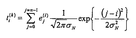
또한, ej (l)은, l번째의 소자 어긋남 템플릿의 화소 j의 값을 나타낸다. 또한 n은, 소정의 방향을 따른 직선 상에 위치하는, 소자 어긋남 템플릿에 포함되는 화소의 총수를 나타낸다. σN 2는 분산을 나타낸다. 이 분산 σN 2는, 불선명량에 상당하고, 분산 σN 2가 클수록, 불선명량도 크다.In addition, e j (l) represents the value of the pixel j of the l-th element shift template. In addition, n represents the total number of pixels contained in the element shift template located on a straight line in a predetermined direction. sigma N 2 represents dispersion. This dispersion sigma N 2 corresponds to an amount of unsharpness, and the larger the amount of dispersion sigma N 2 , the larger the unsharpness amount.
또한, 소정의 방향은, 예를 들면, 수평 방향, 수직 방향 혹은 수평 방향에 대하여 각도 θ(단, 0<θ<180°)를 이루는 방향으로 할 수 있다.The predetermined direction may be, for example, a direction in which the angle θ (where 0 <θ <180 °) is formed with respect to the horizontal direction, the vertical direction, or the horizontal direction.
또한, 초점 위치 어긋남에 의한 불선명을 소자 어긋남 템플릿에 중첩하는 경우, 점퍼짐 함수는, 예를 들면, 2차원의 가우스 분포 함수 또는 제1종 베셀 함수 J1을 주목하는 화소로부터의 거리 x로 나눈 값의 2승 (J1/x)2이어도 된다.In addition, when superimposition due to the focal position shift is superimposed on the element shift template, the jumper function is divided by, for example, the two-dimensional Gaussian distribution function or the first kind of Bessel function J1 divided by the distance x from the pixel of interest. It may be 2 (J1 / x) 2 of the value.
템플릿 생성부(21)는, 손떨림에 의한 불선명과 초점 위치 어긋남에 의한 불선명의 양방을 포함하는 불선명 검출용 템플릿을 생성해도 된다. 이 경우, 템플릿 생성부(21)는, 예를 들면, 소자 어긋남 템플릿과 손떨림용의 점퍼짐 함수와의 컨볼루션 연산을 행하여 얻어진 템플릿과, 초점 위치 어긋남용 점퍼짐 함수와의 컨볼루션 연산을 행한다. 이에 의해, 템플릿 생성부(21)는, 손떨림에 의한 불선명과 초점 위치 어긋남에 의한 불선명의 양방을 포함하는 불선명 검출용 템플릿을 생성할 수 있다.The
또한, 템플릿 생성부(21)는, 리사이즈 템플릿과 불선명 함수와의 컨볼루션 연산을 행하여 불선명 검출용 템플릿을 생성해도 된다. 또한, 불선명 검출용 템플릿은, 기본 템플릿, 각 리사이즈 템플릿 및 각 소자 어긋남 템플릿을 포함해도 된다.In addition, the
마지막으로, 템플릿 생성부(21)는, 얻어진 불선명 검출용 템플릿을 다음 수학식에 따라서 정규화한다.Finally, the

또한, ti (k)는, 불선명 검출용 템플릿 T(k)에 포함되는 화소 i의 값이고, AVG(T(k))는, 불선명 검출용 템플릿 T(k)에 포함되는 화소값의 평균값을 나타내고, STD(T(k))는 불선명 검출용 템플릿 T(k)에 포함되는 화소값의 표준 편차를 나타낸다. 또한 n은, 불선명 검출용 템플릿 T(k)에 포함되는 화소의 총수를 나타낸다. 그리고 tsi (k)는, 정규화된 불선명 검출용 템플릿에 포함되는 화소 i의 값이다.In addition, t i (k) is the value of the pixel i contained in the opacity detection template T (k) , and AVG (T (k) ) is the pixel value included in the opacity detection template T (k) . The average value of is shown, and STD (T (k) ) represents the standard deviation of pixel values contained in the template for detecting opacity T (k) . In addition, n represents the total number of pixels contained in the template T (k) for opacity detection. And ts i (k) is the value of pixel i included in the normalized opacity detection template.
도 7의 (A)∼도 7의 (D)는, 각각, 불선명량이 상이한 수평 방향의 불선명 검출용 템플릿에서의, 흑 블록과 백 블록의 경계 근방에서의 화소값 분포를 도시하는 그래프이다. 도 7의 (A)∼도 7의 (D)에서, 횡축은 수평 방향의 위치를 나타내고, 종축은 화소값을 나타낸다. 또한 그래프(701∼704)는, 각각, 흑 블록과 백 블록의 경계 근방에서의, 불선명 검출용 템플릿의 각 화소의 값을 나타낸다.7A to 7D are graphs showing pixel value distributions in the vicinity of a boundary between a black block and a white block in a template for detecting unclearness in the horizontal direction, each having a different unclear amount. . In FIGS. 7A to 7D, the horizontal axis represents a position in the horizontal direction, and the vertical axis represents a pixel value. Further, the
도 7의 (A)에 도시된 그래프(701)는, 불선명이 중첩되어 있지 않은 불선명 검출용 템플릿에 대응한다. 이 불선명 검출용 템플릿에서는, 흑 블록과 백 블록의 경계가 위치하는 화소의 값만이 백 블록에 포함되는 화소의 값과 흑 블록에 포함되는 화소의 값의 중간의 값을 갖는다.The
그래프(702∼704)는, 각각, 불선명이 중첩된 불선명 검출용 템플릿에 대응한다. 이 중, 그래프(702)에 대응하는 불선명 검출용 템플릿에 중첩된 불선명량이 가장 적고, 한편, 그래프(704)에 대응하는 불선명 검출용 템플릿에 중첩된 불선명량이 가장 많다. 도 7의 (B)∼도 7의 (D)에 도시된 바와 같이, 중첩되는 불선명량이 많을수록, 흑 블록과 백 블록의 경계 근방에서의 화소값의 변화가 완만해진다.The
템플릿 생성부(21)는, 생성한 각 불선명 검출용 템플릿을, 그 템플릿의 생성에 이용된 불선명 함수에 대응하는 불선명량 및 불선명 검출용 템플릿의 식별 번호와 함께 기억부(12)에 기억한다.The
패턴 검출부(22)는, 판독 화상 상에서 위치 검출 마커가 찍혀 있는 영역을 검출한다.The
예를 들면, 패턴 검출부(22)는, 판독 화상과, 위치 검출 마커와 마찬가지의 패턴을 갖는 패턴 검출용 템플릿과의 패턴 매칭을 행하여, 판독 화상과 패턴 검출용 템플릿이 가장 일치하는 위치를 구한다. 구체적으로는, 패턴 검출부(22)는, 판독 화상에 대한 패턴 검출용 템플릿의 상대적인 위치를 변화시키면서, 판독 화상과 패턴 검출용 템플릿과의 대응 화소간의 화소값의 차분 절대값의 합계를 상위도로서 산출한다. 그리고 패턴 검출부(22)는, 상위도가 최소로 되는, 패턴 검출용 템플릿의 위치를, 양자가 가장 일치하는 위치인 패턴 위치로서 특정한다. 그리고 패턴 검출부(22)는, 판독 화상 상에, 패턴 위치를 기준으로 하여, 위치 검출 마커의 사이즈와 동일한 영역, 또는 위치 검출 마커의 사이즈에 소정의 여유분을 가한 사이즈를 갖는 영역을, 패턴 영역으로서 설정한다. 예를 들면, 판독 화상과 패턴 검출용 템플릿이 가장 일치하였을 때의 패턴 검출용 템플릿의 좌상단 화소의 판독 화상 상의 위치가 패턴 위치로 설정된다. 이 경우, 패턴 검출부(22)는, 그 패턴 위치를 좌상단으로 하고, 위치 검출 마커의 수평 방향 사이즈에 1.0∼1.2를 곱한 폭을 갖고, 위치 검출 마커의 수직 방향 사이즈에 1.0∼1.2를 곱한 높이를 갖는 영역을 패턴 영역으로 한다.For example, the
또한, 판독 화상에 찍혀 있는 위치 검출 마커의 사이즈는, 화상 입력 장치(2)와 매체에 인쇄된 암호 화상과의 거리에 따라서 변한다. 따라서, 패턴 검출용 템플릿으로서, 상기의 복수의 리사이즈 템플릿이 이용되어도 된다. 이 경우, 패턴 검출부(22)는, 복수의 리사이즈 템플릿의 각각과, 판독 화상과의 패턴 매칭을 행한다. 그리고 패턴 검출부(22)는, 상위도가 최소로 되는 리사이즈 템플릿에 의해, 패턴 위치를 특정한다. 또한 이 경우, 패턴 검출부(22)는, 상위도가 최소로 되는 리사이즈 템플릿에 대응하는 배율이 클수록, 패턴 영역의 사이즈를 크게 해도 된다. 예를 들면, 패턴 검출부(22)는, 상위도가 최소로 되는 리사이즈 템플릿에 대응하는 배율이 1인 경우, 미리 정해진 기준의 폭 및 높이를 갖는 패턴 영역을 설정한다. 한편, 패턴 검출부(22)는, 배율이 1과 상이한 값을 갖는 경우, 패턴 영역의 기준의 폭 및 높이의 각각에, 그 배율을 곱한 값을, 패턴 영역의 폭 및 높이로 한다.In addition, the size of the position detection marker imprinted on the read image changes depending on the distance between the
또한, 패턴 검출부(22)는, 패턴 위치를 결정하기 위해서, 위치 검출 마커에 포함되는 백 블록과 흑 블록의 경계를 판독 화상 상에서 검출해도 된다. 여기서, 인접하는 2개의 화소간의 차분값의 절대값은, 그 2개의 화소의 한쪽이 백 블록에 포함되고, 다른 쪽이 흑 블록에 포함될 때에 극대값으로 된다. 그리고, 위치 검출 마커는, 교대로 배치된 복수의 백 블록과 흑 블록을 갖기 때문에, 이와 같은 차분 절대값의 극대값은, 백 블록과 흑 블록의 각각의 경계에서 검출된다. 또한, 인접하는 극대값간의 거리는, 백 블록 또는 흑 블록의 길이에, 판독 화상 상에서의 암호 화상의 배율을 곱한 값으로 된다. 따라서, 패턴 검출부(22)는, 판독 화상에 대하여 수평 방향 또는 수직 방향의 근방 화소간의 차분 연산을 실행하여 근방 화소간의 차분 절대값을 산출한다. 그리고 패턴 검출부(22)는, 차분 절대값이 극대값으로 되는 화소인 엣지 화소의 위치를 구한다. 패턴 검출부(22)는, 복수의 엣지 화소 중, 복수의 엣지 화소간의 수평 방향 또는 수직 방향의 거리가, 위치 검출 마커가 갖는 각 백 블록 및 흑 블록의 길이에 일정한 배율을 곱한 값으로 되어 있는 엣지 화소의 조를 검출한다. 그리고 패턴 검출부(22)는, 검출된 엣지 화소의 조를 포함하는 영역을 패턴 영역으로서 설정한다.In addition, the
또한, 패턴 검출부(22)는, 판독 화상과 패턴 검출용 템플릿과의 패턴 매칭에 의해 구해진 패턴 영역 내에서, 상기의 엣지 화소의 검출 및 엣지 화소간의 거리의 산출을 행해도 된다. 이 경우, 패턴 검출부(22)는, 보다 정확하게 패턴 영역을 검출할 수 있으므로, 패턴 매칭에 의해 구해진 패턴 영역 내에, 보다 좁은 패턴 영역을 설정할 수 있다. 그 때문에, 매칭부(23)에 의한, 패턴 영역과 불선명 검출용 템플릿과의 패턴 매칭의 연산량을 경감할 수 있다. 또한, 매칭부(23)의 처리의 상세에 대해서는 후술한다.In addition, the
또한, 패턴 검출부(22)는, 판독 화상 상에서, 미리 정해진 영역을 패턴 영역으로 해도 된다. 예를 들면, 암호 화상이 판독 화상의 1/2보다도 크게 되도록 촬영되는 것이 상정되는 경우, 패턴 검출부(22)는, 판독 화상을 수평 방향 및 수직 방향의 각각으로 2분할한 블록 중, 좌상단의 블록을 패턴 영역으로 설정해도 된다.In addition, the
패턴 검출부(22)는, 패턴 영역의 위치 및 사이즈를 나타내는 정보를 매칭부(23)에 건네준다.The
매칭부(23)는, 기억부(12)에 기억되어 있는 각 불선명 검출용 템플릿과, 판독 화상 중, 패턴 검출부(22)에 의해 검출된 위치 검출 마커가 포함되는 패턴 영역과의 사이에서 패턴 매칭을 실행한다. 그리고 매칭부(23)는, 판독 화상에 포함되는 위치 검출 마커와 가장 일치하는 불선명 검출용 템플릿을 결정한다.The matching
구체적으로는, 매칭부(23)는, 패턴 영역에 대한 불선명 검출용 템플릿의 상대적인 위치를 다양하게 변경하고, 각각의 위치에서 불선명 검출용 템플릿과 패턴 영역과의 상위도를 산출한다. 이 상위도는, 불선명 검출용 템플릿과 패턴 영역의 일치 정도를 나타내는 지표로 된다.Specifically, the
매칭부(23)는, 상위도를 산출할 때, 판독 화상 취득 시의 촬영 환경의 밝기에 따라서 상위도의 값이 변하는 것을 방지하는 것이 바람직하다. 따라서 매칭부(23)는, 패턴 영역 중, 불선명 검출용 템플릿과 동일한 위치 및 동일한 사이즈의 테스트 영역에 포함되는 화소의 값을 다음 수학식에 따라서 정규화한다.The matching

또한, gi는, 테스트 영역 G에 포함되는 화소 i의 값이고, AVG(G)는, 테스트 영역 G에 포함되는 화소값의 평균값을 나타내고, STD(G)는 테스트 영역 G에 포함되는 화소값의 표준 편차를 나타낸다. 또한 n은, 테스트 영역 G에 포함되는 화소의 총수를 나타낸다. 그리고 gsi는, 정규화된 테스트 영역 G에 포함되는 화소 i의 값이다.In addition, g i is the value of pixel i contained in test area G, AVG (G) shows the average value of the pixel value contained in test area G, and STD (G) is the pixel value contained in test area G Represents the standard deviation. N represents the total number of pixels included in the test region G. And gs i is the value of pixel i included in the normalized test region G.
매칭부(23)는, 패턴 영역 중의 다양한 위치에 설정되어, 정규화된 테스트 영역 G와, 불선명 검출용 템플릿과의 상위도를 다음 수학식에 따라서 산출한다.The

단, M(k)는, k번째의 불선명 검출용 템플릿과, 정규화된 테스트 영역 G의 상위도를 나타낸다. gsi는, 정규화된 테스트 영역 G에 포함되는 i번째의 화소의 값을 나타내고, tsi (k)는, k번째의 불선명 검출용 템플릿의 i번째의 화소의 값을 나타낸다. 또한 n은, 테스트 영역 G에 포함되는 화소의 총수를 나타낸다.However, M (k) represents the degree of difference between the k-th unclear detection template and the normalized test region G. FIG. gs i represents the value of the i-th pixel contained in the normalized test area G, and ts i (k) represents the value of the i-th pixel of the k-th opacity detection template. N represents the total number of pixels included in the test region G.
매칭부(23)는, 패턴 영역에 대한 k번째의 불선명 검출용 템플릿의 상대적인 위치를 다양하게 변경하고, 각 위치에 대하여 상위도 M(k)를 산출한다. 그리고 매칭부(23)는, 상위도 M(k) 중의 최소값 Mmin(k)를, k번째의 불선명 검출용 템플릿에 대한 상위도로 한다. 마찬가지로, 매칭부(23)는, 패턴 영역과, 기억부(12)에 기억되어 있는 각 불선명 검출용 템플릿과의 상위도를 산출한다.The
매칭부(23)는, 각 불선명 검출용 템플릿의 상위도 Mmin(k) 중의 최소값 Mmin을 구한다. 그리고 매칭부(23)는, 최소값 Mmin에 대응하는 불선명 검출용 템플릿을, 판독 화상에 포함되는 위치 검출 마커에 대하여 가장 일치하는 템플릿으로 한다.The matching
또한, 매칭부(23)는, 상위도의 역수인 유사도를, 불선명 검출용 템플릿과 패턴 영역과의 일치 정도를 나타내는 지표로서 구해도 된다. 이 경우, 매칭부(23)는, 유사도가 최대로 되는 불선명 검출용 템플릿을, 판독 화상에 포함되는 위치 검출 마커에 대하여 가장 일치하는 템플릿으로 한다.In addition, the matching
매칭부(23)는, 판독 화상에 포함되는 위치 검출 마커와 가장 일치한 불선명 검출용 템플릿의 식별 번호를 판정부(24)에 통지한다.The
판정부(24)는, 매칭부(23)에 의해 구해진, 판독 화상에 포함되는 위치 검출 마커와 가장 일치한 불선명 검출용 템플릿에 대응하는 불선명량 d를 판독 화상에 중첩되어 있는 불선명량이라고 추정한다. 그리고 판정부(24)는, 판독 화상에 중첩되어 있는 불선명량 d에 따라서, 판독 화상을 보정할지의 여부, 혹은 판독 화상을 재취득할지의 여부를 판정한다.The
예를 들면, 판정부(24)는, 기억부(12)로부터, 판독 화상과 가장 일치한 불선명 검출용 템플릿의 식별 번호에 대응하는 불선명량 d를 읽어들인다. 그리고 판정부(24)는, 그 불선명량 d를 제1 임계값 Th1과 비교한다. 그리고 판정부(24)는, 불선명량 d가 제1 임계값 Th1보다도 클 때, 판독 화상을 폐기한다. 그리고 판정부(24)는, 판독 화상이 불선명한 것을 처리부(13)에 통지한다. 이 경우, 처리부(13)는, 도시하지 않은 유저 인터페이스를 통하여, 유저에 대하여 암호 화상을 재차 촬영하는 것을 요구하는 메시지를 통지한다. 혹은, 동일한 암호 화상을 촬영한 복수의 판독 화상이 기억부(12)에 기억되어 있는 경우, 처리부(13)는, 폐기된 판독 화상과 상이한 판독 화상을 기억부(12)로부터 읽어들인다.For example, the
그리고 처리부(13)는, 재취득된 판독 화상을 이용하여 재차 불선명량의 검출을 행하게 한다.Then, the
또한, 제1 임계값 Th1은, 예를 들면, 암호 화상을 복호할 수 있는 불선명량의 상한값에 대응하는 값으로 설정된다. 혹은, 제1 임계값 Th1은, 암호 화상을 복호하여 얻어지는 복호 화상에 포함되는 정보를 유저가 판독할 수 있는 불선명량의 상한값으로 설정되어도 된다.In addition, the 1st threshold value Th1 is set to the value corresponding to the upper limit of the amount of non-clarity which can decrypt an encrypted image, for example. Alternatively, the first threshold value Th1 may be set to an upper limit value of the amount of unsharpness that the user can read information included in the decoded image obtained by decoding the encrypted image.
또한, 판정부(24)는, 불선명량 d가 제1 임계값 이하인 경우, 그 불선명량 d를, 제1 임계값 Th1보다도 작은 제2 임계값 Th2와 비교한다. 그리고 판정부(24)는, 불선명량 d가 제2 임계값 Th2보다도 큰 경우, 판독 화상에 대하여 보정이 필요한 것을 처리부(13)에 통지한다. 그리고 처리부(13)는, 보정부(25)에 대하여, 매칭부(23)로부터 수취한 불선명 검출용 템플릿의 식별 번호에 대응하는 불선명량 d 및 판독 화상을 건네준다.In addition, when the amount of unsharpness d is equal to or less than the first threshold value, the
한편, 불선명량 d가 제2 임계값 Th2 이하인 경우, 판정부(24)는, 판독 화상의 화질은 양호하다고 판정한다. 그리고 판정부(24)는, 그 판정 결과를 처리부(13)에 전달한다.On the other hand, when the non-clarity amount d is equal to or less than the second threshold Th2, the
또한, 제2 임계값 Th2는, 예를 들면, 암호 화상으로부터 복호함으로써 얻어지는 복호 화상의 화질이 양호하지 않다고 판단되는 불선명량의 하한값으로 설정된다.In addition, the second threshold Th2 is set to a lower limit of the amount of unsharpness determined, for example, that the image quality of the decoded image obtained by decoding from the encrypted image is not good.
또한, 동일한 불선명량이 중첩되어 있어도, 판독 화상에 찍혀 있는 암호 화상의 영역이 클수록, 암호 화상에 대한 상대적인 불선명은 작으므로, 암호 화상으로부터 복호되는 복호 화상의 화질은 양호하게 된다. 따라서, 제1 임계값 Th1 및 제2 임계값 Th2는, 판독 화상에 찍혀 있는 암호 화상의 영역이 클수록, 큰 값이어도 된다.Further, even if the same amount of unsharpness overlaps, the larger the area of the encrypted image imprinted on the read image is, the smaller the relative unsharpness relative to the encrypted image is, so that the image quality of the decoded image decoded from the encrypted image becomes better. Therefore, the first threshold value Th1 and the second threshold value Th2 may be larger as the area of the encrypted image imprinted on the read image is larger.
이 경우, 기억부(12)는, 불선명 검출용 템플릿의 식별 번호와 함께, 그 템플릿의 생성에 이용된 리사이즈 템플릿에 따른 배율을 기억한다. 판정부(24)는, 판독 화상과 가장 일치한 불선명 검출용 템플릿의 식별 번호에 대응하는 배율을 기억부(12)로부터 읽어들인다. 그리고 판정부(24)는, 그 배율을, 제1 임계값 Th1의 기준값 및 제2 임계값 Th2의 기준값에 곱한 값을, 각각 제1 임계값 Th1 및 제2 임계값 Th2로 한다.In this case, the memory |
보정부(25)는, 처리부(13)로부터 건네받은 불선명량에 따라서, 판독 화상에 대하여 엣지 강조 처리를 실행한다.The
예를 들면, 보정부(25)는, 판독 화상을 푸리에 변환하여, 주파수 화상을 생성한다. 그리고 보정부(25)는, 주파수 화상의 각 주파수 성분에 대하여 강조 계수α(u, v)를 곱함으로써, 보정 주파수 화상을 생성한다. 또한, u는 수평 방향의 주파수를 나타내고, v는 수직 방향의 주파수를 나타낸다. 또한 강조 계수 α(u, v)는, 예를 들면, 소정의 주파수 (u0, v0)보다도 절대값이 큰 주파수 (u, v)에 대하여 1보다도 큰 값, 예를 들면, 1.1∼2의 범위 내의 값이며, 소정의 주파수 (u0, v0) 이하의 주파수의 절대값에 대하여 1이다. 또한, 강조 계수 α(u, v)는, 소정의 주파수 (u0, v0)보다도 절대값이 큰 주파수 (u, v)에 대해서도, 주파수 대역마다 상이한 값이어도 된다.For example, the
위치 검출 마커와 가장 일치하는 불선명 검출용 템플릿이, 소정의 1차원의 방향에만 불선명을 갖는 템플릿인 경우도 있다. 이 경우, 보정부(25)는, 그 불선명한 방향의 주파수 성분에 대한 강조 계수의 값을 불선명한 방향과 직교하는 방향의 주파수 성분에 대한 강조 계수보다도 크게 해도 된다. 예를 들면, 위치 검출 마커와 가장 일치하는 불선명 검출용 템플릿에는 수평 방향의 불선명량만이 중첩되어 있는 경우, 보정부(25)는, v=0 또한 |u|〉u0에 대응하는 강조 계수 α(u, v)의 값을 1보다도 크게 설정하고, 한편, u=0에 대응하는 강조 계수 α(u, v)의 값을 v에 상관없이 1로 설정한다.In some cases, the opacity detection template that most closely matches the position detection marker may be a template having opacity only in a predetermined one-dimensional direction. In this case, the
그 후, 보정부(25)는, 보정 주파수 화상을 역푸리에 변환함으로써, 엣지 강조한 보정 화상을 얻는다.Thereafter, the
보정부(25)는, 불선명량이 클수록, 소정의 주파수 (u0, v0)을 낮은 값으로 설정하는 것이 바람직하다. 이와 같이 주파수 (u0, v0)을 설정함으로써, 불선명량이 클수록, 낮은 주파수 성분도 강조되므로, 보정 화상에서도 보다 엣지가 강조된다.It is preferable that the
또한, 보정부(25)는, 다른 엣지 강조 처리를 이용하여, 예를 들면, 주목 화소의 값과 주목 화소의 주위에 설정된 언샤프 마스크 내의 평균 화소값과의 차에 강조 계수를 곱한 값을 주목 화소의 값에 가산함으로써, 엣지 강조한 보정 화상을 생성해도 된다. 이 경우, 보정부(25)는, 불선명량이 클수록, 언샤프 마스크의 사이즈를 크게 한다. 또한 판독 화상과 가장 일치하는 불선명 검출용 템플릿이, 소정의 1차원의 방향에만 불선명을 갖는 템플릿이면, 보정부(25)는, 언샤프 마스크를, 불선명이 중첩된 방향의 길이가, 불선명이 중첩되어 있지 않은 방향의 길이보다도 길어지도록 설정한다. 예를 들면, 판독 화상과 가장 일치하는 불선명 검출용 템플릿에는 수직 방향의 불선명량만이 중첩되어 있는 경우, 보정부(25)는, 언샤프 마스크의 수평 방향의 길이를 1화소로 하고, 언샤프 마스크의 수직 방향의 길이를 불선명량에 따라서 수 화소∼십십 화소 정도로 설정한다.The
보정부(25)는, 보정 화상을 복호부(26)에 건네준다.The
복호부(26)는, 판독 화상 또는 보정 화상에 대하여 복호 처리를 실행함으로써, 복호 화상을 생성한다.The
여기서, 복호부(26)에 의해 실행되는 복호 처리의 이해를 용이하게 하기 위해서, 원화상에 대하여 행해지는 암호화 처리의 일례를 설명한다.Here, an example of encryption processing performed on the original image will be described in order to facilitate understanding of the decoding processing executed by the
암호화 처리를 실행하는 암호화 장치는, 우선, 원화상 중, 암호화하는 영역을 복수의 블록으로 분할하고, 각 블록에 고유의 번호를 설정한다. 예를 들면, 암호화 장치는, 암호화하는 영역을 세로 3개×가로 4개의 합계 12개의 블록으로 분할하고, 각각의 블록에 1∼12의 번호를 붙인다. 다음으로, 암호화 장치는, 암호키를 이용하여 각 블록의 위치를 교체하는 스크램블 처리를 실행한다. 그를 위해서, 암호화 장치는, 암호키로부터 변환 전과 변환 후의 블록의 위치 관계를 나타내는 대응 테이블을 작성한다. 예를 들면, 변환 후의 블록의 번호가 x로 표시되고, 변환 전의 블록의 번호가 y로 표시되는 것으로 한다. 이때, 스크램블 처리에 대응하는 블록의 변환 식은 다음 수학식으로 표현된다.An encryption apparatus that performs encryption processing first divides an area to be encrypted into a plurality of blocks among original images, and sets a unique number to each block. For example, the encryption apparatus divides the area to be encrypted into 12 blocks of 3 pieces in total length x 4 pieces, and assigns 1 to 12 numbers to each block. Next, the encryption apparatus executes a scramble process of replacing the position of each block by using the encryption key. For that purpose, the encryption apparatus creates a correspondence table indicating the positional relationship between the blocks before and after the conversion from the encryption key. For example, it is assumed that the number of blocks after conversion is indicated by x, and the number of blocks before conversion is indicated by y. At this time, the transform equation of the block corresponding to the scramble process is expressed by the following equation.
![]()
![]()
수학식 7에서, p 및 q는, 각각, 암호키가 나타내는 소수이다.In
도 8에, 원화상을 세로 3개×가로 4개의 블록으로 분할하고, p=7, q=13으로 하였을 때의, 원화상 상의 각 블록의 위치와, 스크램블 처리 후의 화상에서의 각 블록의 위치와의 관계를 도시한다.8 shows the position of each block on the original image and the position of each block in the image after the scramble process when the original image is divided into three vertically x four horizontal blocks, and p = 7 and q = 13. The relationship with
도 8에서, 화상(801)은 원화상이고, 화상(802)은, 원화상(801)에 대하여 스크램블 처리가 실시된 암호 화상이다. 또한 원화상(801) 및 암호 화상(802)의 각 블록 내에 나타내어진 번호는, 원화상에서의 블록의 번호를 나타낸다. 예를 들면, 수학식 7로부터, x가 1일 때, 대응하는 y의 값은 7로 된다. 따라서, 암호화 장치는, 변환 전의 블록 번호 y가 7인 블록을, 스크램블 처리에 의해, 변환 후의 블록 번호 x가 1인 블록의 위치로 이동한다.In FIG. 8, the
이하에서는, 스크램블 처리에 의해 화소의 위치를 다른 위치로 이동시키는 단위인 이 블록을, 위치 변환 블록이라고 부른다.Hereinafter, this block, which is a unit for moving the position of the pixel to another position by the scrambling process, is called a position conversion block.
복호부(26)는, 위치 검출용 마커의 위치에 의해, 판독 화상에서 암호 화상이 찍혀 있는 암호 영역을 특정한다. 그리고 복호부(26)는, 암호 영역에 대하여 역스크램블 처리를 실행한다. 복호부(26)는, 스크램블 처리를 실행하였을 때의 암호키 및 블록 위치를 변환하는 수학식 7을 이용하여, 스크램블 처리 실행 후의 위치 변환 블록의 위치가 x로 되는, 암호 화상 내의 위치 변환 블록의 원래의 위치 y를 결정할 수 있다. 그리고 복호부(26)는, 암호 화상 내의 각 위치 변환 블록을, 얻어진 원래의 위치 변환 블록의 위치로 이동시킴으로써, 각 위치 변환 블록의 위치가 원화상에서의 위치와 동일하게 되는 복호 화상을 생성할 수 있다.The
복호부(26)는, 복호 화상을 출력한다.The
도 9는 화상 처리 장치의 처리부 상에서 실행되는 컴퓨터 프로그램에 의해 제어되는 화상 처리의 동작 플로우차트이다.9 is an operational flowchart of image processing controlled by a computer program executed on a processing unit of the image processing apparatus.
처리부(13)는, 화상 입력 장치(2) 또는 기억부(12)로부터 판독 화상을 취득한다(스텝 S201). 그리고 처리부(13)는, 판독 화상을 패턴 검출부(22)에 건네준다.The
패턴 검출부(22)는, 판독 화상으로부터 기지의 패턴인 위치 검출 마커를 포함하는 패턴 영역을 검출한다(스텝 S202). 그리고 패턴 검출부(22)는, 패턴 영역의 위치 및 사이즈를 나타내는 정보를 매칭부(23)에 통지한다.The
매칭부(23)는, 패턴 영역과 각 불선명 검출용 템플릿과의 상위도를 산출한다(스텝 S203). 그리고 매칭부(23)는, 상위도가 최소로 되는 불선명 검출용 템플릿을, 판독 화상에 찍혀 있는 위치 검출 마커와 가장 일치하는 불선명 검출용 템플릿으로서 특정한다(스텝 S204). 매칭부(23)는, 상위도가 최소로 되는 불선명 검출용 템플릿에 대응하는 식별 번호를 판정부(24)에 통지한다.The
판정부(24)는, 판독 화상에 포함되는 위치 검출 마커와 가장 일치하는 불선명 검출용 템플릿에 대응하는 식별 번호를 참조하여, 기억부(12)로부터 그 불선명 검출용 템플릿에 대응하는 불선명량 d를 읽어들인다. 그리고 판정부(24)는, 판독 화상에 포함되는 위치 검출 마커와 가장 일치하는 불선명 검출용 템플릿에 대응하는 불선명량 d는 제1 임계값 Th1보다 큰지의 여부를 판정한다(S205). 불선명량 d가 제1 임계값 Th1보다 큰 경우(스텝 S205-예), 판정부(24)는, 판독 화상에 중첩된 불선명량이 큰 것을 처리부(13)에 통지한다. 이 경우, 처리부(13)는, 암호 화상의 재판독을 행하는 메시지를, 도시하지 않은 유저 인터페이스를 통하여 유저에게 통지한다(스텝 S206). 그 후, 처리부(13)는, 스텝 S201 이후의 처리를 반복한다.The
한편, 불선명량 d가 제1 임계값 Th1 이하인 경우(스텝 S205-아니오), 판정부(24)는, 불선명량 d는 제2 임계값 Th2보다 큰지의 여부를 판정한다(스텝 S207). 불선명량 d가 제2 임계값 Th2보다 큰 경우(스텝 S207-예), 판정부(24)는, 판독 화상에 대하여 보정이 필요한 것을 처리부(13)에 통지한다. 그리고 처리부(13)는, 보정부(25)에, 불선명량 d 및 판독 화상을 건네준다. 보정부(25)는, 판독 화상에 대하여, 불선명량 d에 따른 엣지 강조 처리 등의 보정 처리를 실행한다(스텝 S208). 그리고 보정부(25)는, 보정 처리를 행함으로써 생성된 보정 화상을 복호부(26)에 건네준다.On the other hand, when the amount of unsharpness d is equal to or less than the first threshold Th1 (step S205-no), the
한편, 불선명량 d가 제2 임계값 Th2 이하인 경우(스텝 S207-아니오), 복호부(26)는, 판독 화상에 대하여 복호 처리를 행하여, 복호 화상을 생성한다(스텝 S209). 또한 스텝 S208 후, 복호부(26)는, 보정 화상에 대하여 복호 처리를 행하여, 복호 화상을 생성한다(스텝 S209).On the other hand, when the amount of unsharpness d is equal to or less than the second threshold Th2 (step S207-no), the
그리고 처리부(13)는, 판독 화상에 대한 처리를 종료한다.And the
이상에 설명한 바와 같이, 제1 실시 형태에 따른 화상 처리 장치는, 매체에 인쇄된 화상에 포함되는 기지의 패턴에 대하여, 그 패턴에 소정의 불선명량을 중첩시킨 복수의 불선명 검출용 템플릿 중, 가장 일치하는 템플릿을 특정한다. 그리고 이 화상 처리 장치는, 가장 일치한다고 판정된 템플릿에 대한 불선명량을, 판독 화상에 중첩된 불선명량으로서 추정한다. 그 때문에, 이 화상 처리 장치는, 판독 화상에 중첩된 불선명량을 정확하게 추정할 수 있다. 그리고 이 화상 처리 장치는, 판독 화상에 중첩된 불선명량에 따라서, 화상의 재판독이 필요한지의 여부, 또는 화상에 대한 보정 처리가 필요한지의 여부를 판정할 수 있다.As described above, the image processing apparatus according to the first embodiment includes, among the plurality of templates for detecting the unclearness, in which a predetermined amount of unsharpness is superimposed on the pattern with respect to a known pattern included in the image printed on the medium. Specify the template that best matches. And this image processing apparatus estimates the amount of unsharpness with respect to the template determined as the best match as the amount of unsharpening superimposed on a read image. Therefore, this image processing apparatus can accurately estimate the amount of non-sharpening superimposed on the read image. Then, the image processing apparatus can determine whether or not re-reading of the image is necessary or whether correction processing for the image is necessary, in accordance with the amount of unsharpness superimposed on the read image.
다음으로, 제2 실시 형태에 따른, 화상 처리 장치에 대하여 설명한다.Next, an image processing apparatus according to the second embodiment will be described.
도 10은 제2 실시 형태에 따른 처리부(13)의 기능 블록도이다. 도 10에 도시된 바와 같이, 처리부(13)는, 프레임간 판정부(20)를 갖는다. 또한, 도 10에서, 처리부(13)의 각 기능 블록에는, 도 4에 도시된 처리부(13)의 대응하는 기능 블록과 동일한 참조 번호를 붙였다.10 is a functional block diagram of the
제2 실시 형태에 따른 화상 처리 장치는, 제1 실시 형태에 따른 화상 처리 장치와 비교하여, 프레임간 판정부(20)에 의해, 동일한 암호 화상을 촬영하여 얻어진 복수의 판독 화상이 상위한지의 여부로 판독 화상에 불선명이 중첩되어 있는지의 여부를 판정하는 점에서 상이하다. 따라서 이하에서는, 프레임간 판정부(20)에 대하여 설명한다.In the image processing apparatus according to the second embodiment, compared with the image processing apparatus according to the first embodiment, whether the plurality of read images obtained by capturing the same encrypted image by the
프레임간 판정부(20)는, 동일한 암호 화상을 촬영한 2매의 판독 화상간에서 프레임간 차분 처리를 실행하여 이 2매의 판독 화상간의 상위도를 산출한다. 그 상위도가 소정의 임계값보다도 큰 경우, 프레임간 판정부(20)는, 그 2매의 판독 화상 중의 적어도 한쪽에는 불선명이 중첩되어 있다고 판정한다. 그리고 프레임간 판정부(20)는, 그 2매의 판독 화상 중 어느 한쪽 또는 양방을 폐기한다.The
따라서, 프레임간 판정부(20)는, 예를 들면, 2매의 판독 화상의 동일한 위치의 화소간에서, 화소값의 차분 절대값을 구하고, 화상 전체에서의 그 차분 절대값의 총합을, 2매의 판독 화상간의 상위도로서 산출한다. 그리고 프레임간 판정부(20)는, 상위도가 소정의 임계값보다도 작으면, 그들 2매의 판독 화상의 어느 것에 대해서도 중첩된 불선명량은 적어, 2매의 판독 화상은 일치한다고 판정한다. 그리고 프레임간 판정부(20)는, 그들 2매의 판독 화상 중 어느 한쪽을 처리부(13)에 건네준다. 그리고 처리부(13)는, 프레임간 판정부(20)로부터 수취한 판독 화상에 대하여, 상기의 제1 실시 형태에 따른 처리를 실행한다.Therefore, the
한편, 상위도가 소정의 임계값 이상인 경우, 프레임간 판정부(20)는, 2매의 판독 화상 중의 적어도 어느 한쪽이 크게 불선명하다고 판정한다. 그리고 프레임간 판정부(20)는, 2매의 판독 화상이 일치하지 않는 것을 처리부(13)에 통지한다. 이 경우, 처리부(13)는, 2매의 판독 화상 중의 적어도 어느 한쪽, 예를 들면, 먼저 생성된 판독 화상을 폐기한다. 그리고 처리부(13)는, 도시하지 않은 유저 인터페이스를 통하여, 암호 화상을 재차 촬영하도록 유저에게 통지한다. 혹은, 기억부(12)에 동일한 암호 화상을 촬영한 다른 판독 화상이 기억되어 있는 경우, 처리부(13)는, 기억부(12)로부터 그 판독 화상을 읽어들여, 프레임간 판정부(20)에 건네준다. 그리고 프레임간 판정부(20)는, 새롭게 취득한 판독 화상과, 폐기되어 있지 않은 쪽의 판독 화상이 일치하는지의 여부, 혹은 새롭게 취득한 2매의 판독 화상이 일치하는지의 여부를 판정한다.On the other hand, when the degree of difference is greater than or equal to the predetermined threshold, the
또한, 매체 상에서 암호 화상이 인쇄되어 있지 않은 영역에 아무것도 인쇄되어 있지 않은 경우와 같이, 판독 화상에서 암호 화상이 포함되는 영역 이외의 영역에 포함되는 각 화소의 값이 대략 동일하게 되는 경우가 있다. 이와 같은 경우, 상기한 바와 같이, 판독 화상 전체에서 프레임간 차분이 행해지면, 화소값이 대략 동일하게 되는 영역에서는, 불선명량이 커져도 프레임간에서의 화소값의 차가 작아지므로, 상위도는 작아질 가능성이 있다.In addition, as in the case where nothing is printed in the area where the encrypted image is not printed on the medium, the value of each pixel included in an area other than the area containing the encrypted image in the read image may be substantially the same. In such a case, as described above, when the interframe difference is performed in the entire read image, in the region where the pixel values are approximately the same, the difference in pixel values between frames becomes small even if the amount of opacity increases, so that the degree of difference becomes small. There is a possibility.
따라서, 프레임간 판정부(20)는, 2개의 판독 화상을, 각각, 복수의 블록으로 분할하고, 2개의 판독 화상 중의 동일한 위치에 있는 블록마다 상위도를 산출해도 된다. 그리고 프레임간 판정부(20)는, 상위도의 최대값을 구하고, 그 상위도의 최대값이 소정의 임계값보다도 크면, 2매의 판독 화상 중의 적어도 어느 한쪽이 크게 불선명하다고 판정해도 된다.Therefore, the
또한, 암호 화상이 촬영되었을 때의 촬영 환경의 밝기 등에 의해, 판독 화상마다, 화상 전체 또는 화상의 일부의 밝기가 상이한 경우도 있다. 따라서, 프레임간 판정부(20)는, 2매의 판독 화상 각각의 화소의 값을 정규화한 후에, 그들 2매의 판독 화상간의 상위도를 산출해도 된다. 이 경우, 프레임간 판정부(20)는, 예를 들면, 테스트 영역을 판독 화상 전체로 하여, 상기의 수학식 5를 이용하여 판독 화상을 정규화할 수 있다.In addition, the brightness of the entire image or a part of the image may be different for each read image, depending on the brightness of the shooting environment when the encrypted image is captured. Therefore, the
또한, 암호 화상이 촬영되었을 때의 매체와 화상 입력 장치(2)간의 상대적인 위치 관계에 따라서, 판독 화상 상에서 암호 화상이 찍혀 있는 암호 영역의 위치 및 암호 영역의 사이즈도 변화한다. 따라서, 프레임간 판정부(20)는, 각 판독 화상에 대하여 패턴 검출부(22)의 처리와 마찬가지의 처리를 행하여, 복수의 위치 검출 마커의 위치를 구함으로써, 각 판독 화상 상에서의 암호 영역을 특정해도 된다. 그리고 프레임간 판정부(20)는, 한쪽의 판독 화상에 대하여 아핀 변환 등의 위치 변환 처리를 행하여, 2매의 판독 화상 상의 암호 영역의 위치 및 사이즈를 일치시킨다. 그리고 프레임간 판정부(20)는, 암호 영역끼리에서 프레임간 차분을 행하여 상위도를 산출해도 된다.Further, depending on the relative positional relationship between the medium and the
도 11은 제2 실시 형태에 따른 화상 처리 장치의 처리부(13) 상에서 실행되는 컴퓨터 프로그램에 의해 제어되는 화상 처리의 동작 플로우차트이다. 또한, 도 11에 도시된 플로우차트에서, 스텝 S304∼S311의 처리는, 각각, 도 9에 도시된 플로우차트의 스텝 S202∼S209의 처리와 동일하다. 따라서 이하에서는, 스텝 S301∼S303에 대하여 설명한다.11 is an operation flowchart of image processing controlled by a computer program executed on the
처리부(13)는, 기억부(12)로부터 2매의 판독 화상을 취득한다(스텝 S301). 그리고 처리부(13)는, 2매의 판독 화상을 프레임간 판정부(20)에 건네준다.The
프레임간 판정부(20)는, 2매의 판독 화상 전체 혹은 2매의 판독 화상의 적어도 일부의 영역에 대하여, 상위도를 산출한다(스텝 S302). 그리고 프레임간 판정부(20)는, 상위도가 소정의 임계값 Th3보다도 작은지의 여부를 판정한다(스텝 S303).The
상위도가 임계값 Th3보다도 작은 경우(스텝 S303-예), 프레임간 판정부(20)는, 2매의 판독 화상 중의 한쪽을 처리부(13)에 건네준다. 그리고 처리부(13)는, 프레임간 판정부(20)로부터 수취한 판독 화상에 대하여, 스텝 S304∼S311의 처리를 실행한다.When the degree of difference is smaller than the threshold value Th3 (step S303-YES), the
한편, 상위도가 임계값 Th3 이상인 경우(스텝 S303-아니오), 프레임간 판정부(20)는, 2매의 판독 화상이 일치하지 않는 것을 처리부(13)에 통지한다. 처리부(13)는, 2매의 판독 화상 중의 적어도 한쪽을 폐기한다. 그리고 처리부(13)는, 암호 화상을 재차 촬영하도록, 유저에게 통지한다(스텝 S308). 그 후, 처리부(13)는, 스텝 S301 이후의 처리를 반복한다.On the other hand, when the degree of difference is greater than or equal to the threshold Th3 (step S303-No), the
이상에 설명한 바와 같이, 제2 실시 형태에 따른 화상 처리 장치는, 동일한 암호 화상을 촬영한 2매의 판독 화상을 비교하여, 양 화상이 일치한 경우에 한하여, 한쪽의 판독 화상에 중첩되어 있는 불선명량을 검출한다. 그 때문에, 이 화상 처리 장치는, 어느 한쪽의 판독 화상이 불선명한 경우에, 불선명량을 검출할 때의 템플릿 매칭 처리를 생략할 수 있다. 따라서, 이 화상 처리 장치는, 불선명량을 검출하기 위한 연산량을 경감할 수 있다.As described above, the image processing apparatus according to the second embodiment compares two read images obtained by photographing the same encrypted image, and is superimposed on one read image only when both images match. Detect light amount. Therefore, this image processing apparatus can omit the template matching process at the time of detecting an amount of unsharpness, when either read image is unclear. Therefore, this image processing apparatus can reduce the amount of calculation for detecting the amount of unsharpness.
또한, 본 발명은, 상기의 실시 형태에 한정되는 것은 아니다.In addition, this invention is not limited to said embodiment.
다른 실시 형태에 따르면, 불선명 검출용 템플릿은, 상기의 각 실시 형태에 따른 불선명 검출용 템플릿을, 푸리에 변환 또는 이산 코사인 변환 등의 주파수 변환 처리를 이용하여 주파수 스펙트럼으로 변환한 것이어도 된다. 이 경우, 불선명 검출용 템플릿은, 위치 검출 마커와 같은 기지의 패턴에 소정의 불선명량이 중첩된 화소값의 분포에 대한 주파수 스펙트럼을 나타낸다. 일반적으로, 패턴에 중첩되는 불선명량이 커질수록, 백 블록과 흑 블록의 경계 부분의 화소값의 변화가 완만하게 되므로, 불선명 검출용 템플릿에 대응하는 주파수 스펙트럼에 포함되는 고주파수 성분은 저하된다.According to another embodiment, the opacity detection template may be obtained by converting the opacity detection template according to each of the above embodiments into a frequency spectrum using frequency conversion processing such as Fourier transform or discrete cosine transform. In this case, the opacity detection template shows a frequency spectrum with respect to a distribution of pixel values in which a predetermined opacity amount is superimposed on a known pattern such as a position detection marker. In general, as the amount of unsharpness superimposed on the pattern increases, the change in the pixel value of the boundary between the back block and the black block is slower, so that the high frequency component included in the frequency spectrum corresponding to the unsharpness detection template decreases.
이와 같은 주파수 스펙트럼을 나타내는 불선명 검출용 템플릿이 이용되는 경우, 매칭부는, 테스트 영역도 주파수 스펙트럼으로 변환한다. 그리고 매칭부(23)는, 테스트 영역의 주파수 스펙트럼과, 불선명 검출용 템플릿의 주파수 스펙트럼과의 사이에서, 각 주파수에서의 성분값의 차의 절대값 합을 상위도로서 구한다.When the opacity detection template which exhibits such a frequency spectrum is used, a matching part converts a test area also into a frequency spectrum. The
또 다른 실시 형태에 따르면, 매칭부는, 판독 화상에 찍혀 있는 복수의 위치 검출 마커에 대하여, 각각 가장 일치하는 불선명 검출용 템플릿을 구해도 된다. 이 경우, 판정부는, 각 위치 검출 마커와 가장 일치한다고 판정된 불선명 검출용 템플릿의 각각에 대응하는 불선명량의 평균값 또는 총합을, 판독 화상에 중첩되어 있는 불선명량으로 해도 된다.According to still another embodiment, the matching unit may obtain a template for detecting opacity that most matches the plurality of position detection markers imprinted on the read image. In this case, the determining unit may set the average value or the sum of the amount of unsharpness corresponding to each of the unsharpness detection templates which are determined to most match each position detection marker as the unsharpness amount superimposed on the read image.
또 다른 실시 형태에 따르면, 화상 처리 장치의 기억부는, 다른 장치에 의해 미리 생성된 불선명 검출용 템플릿을 기억해도 된다. 이 경우, 화상 처리 장치의 처리부에서, 템플릿 생성부의 기능은 생략되어도 된다.According to still another embodiment, the storage unit of the image processing apparatus may store a template for detecting opacity previously generated by another apparatus. In this case, the function of the template generating unit may be omitted in the processing unit of the image processing apparatus.
또 다른 실시 형태에 따르면, 매체에 인쇄된 화상이 2차원 코드 등, 기지의 패턴을 포함하지만, 암호화되어 있지 않은 화상인 경우, 화상 처리 장치의 처리부는, 복호부를 갖지 않아도 된다. 대신에, 처리부는, 2차원 코드에 포함되는 정보를 추출하기 위한 정보 추출부를 갖고 있어도 된다. 정보 추출부는, 2차원 코드에 대하여 미리 정해진 규칙에 따라서, 판독 화상에 포함되는 2차원 코드로부터 정보를 추출한다.According to still another embodiment, when the image printed on the medium contains a known pattern such as a two-dimensional code, but is an image that is not encrypted, the processing unit of the image processing apparatus may not have a decoding unit. Instead, the processing unit may have an information extraction unit for extracting information included in the two-dimensional code. The information extraction unit extracts information from the two-dimensional code included in the read image according to a predetermined rule for the two-dimensional code.
또한, 다른 실시 형태에서, 화상 처리 장치의 처리부는, 보정부를 갖고 있지 않아도 된다. 이 경우, 도 9에 도시된 플로우차트에서의 스텝 S207 및 S208의 처리, 및 도 11에 도시된 플로우차트에서의 스텝 S309 및 S310의 처리는 생략된다.In another embodiment, the processing unit of the image processing apparatus may not have a correction unit. In this case, the processing of steps S207 and S208 in the flowchart shown in FIG. 9 and the processing of steps S309 and S310 in the flowchart shown in FIG. 11 are omitted.
또한, 상기의 각 실시 형태에 따른 화상 처리 장치에 의한 처리의 대상으로 되는 화상은, 인쇄 이외의 방법으로 매체 상에 표시된 것이어도 된다.In addition, the image used as the object of the process by the image processing apparatus which concerns on said each embodiment may be displayed on the medium by methods other than printing.
화상 입력 장치에 의해 전자 데이터화된 암호 화상은, 컬러 화상이어도 된다. 예를 들면, 전자 데이터화된 암호 화상이, 적(R), 녹(G), 청(B)의 3색의 각각마다 휘도 정보를 갖고 있는 경우, 각 실시 형태에 따른 화상 처리 장치는, 각 색 중 어느 하나에 대하여 상기의 화상 처리를 실행해도 된다. 혹은 화상 처리 장치는, 판독 화상에 대하여 HSV 색 공간으로 변환하는 색 변환 처리를 행하여, 각 화소의 휘도 정보를 구하고, 그 휘도 정보에 기초하여 상기의 처리를 실행해도 된다.The encrypted image electronically dataed by the image input device may be a color image. For example, when the encrypted image converted into electronic data has luminance information for each of the three colors of red (R), green (G), and blue (B), the image processing apparatus according to each embodiment includes each color. The image processing may be performed on any one of the above. Alternatively, the image processing apparatus may perform color conversion processing for converting the read image into the HSV color space, obtain luminance information of each pixel, and perform the above processing based on the luminance information.
또한, 제1 실시 형태 또는 제2 실시 형태의 화상 처리 장치의 처리부가 갖는 각 기능을 컴퓨터에 실현시키는 컴퓨터 프로그램은, 컴퓨터에 의해 판독 가능한 매체에 기록된 형태로 제공되어도 된다.Moreover, the computer program which makes a computer realize each function which the processing part of the image processing apparatus of 1st Embodiment or 2nd Embodiment has may be provided in the form recorded on the medium which can be read by a computer.
여기에 예시한 모든 예 및 특정한 용어는, 독자가, 본 발명 및 해당 기술의 촉진에 대한 본 발명자에 의해 기여된 개념을 이해하는 것을 돕는, 교시적인 목적에서 의도된 것이며, 본 발명의 우위성 및 열등성을 나타내는 것에 관한, 본 명세서의 어떠한 예의 구성, 그와 같은 특정한 예 및 조건에 한정되지 않도록 해석되어야 할 것이다. 본 발명의 실시 형태는 상세하게 설명되어 있지만, 본 발명의 정신 및 범위로부터 벗어나지 않고, 다양한 변경, 치환 및 수정을 이것에 가하는 것이 가능한 것을 이해하기 바란다.All examples and specific terms exemplified herein are intended for teaching purposes to assist the reader in understanding the concepts contributed by the inventors for the invention and the promotion of the technology, and the superiority and inferiority of the invention. It should be construed that the present invention is not limited to the configuration of any examples herein, such specific examples and conditions. Although embodiments of the present invention have been described in detail, it should be understood that various changes, substitutions, and modifications can be made thereto without departing from the spirit and scope of the invention.
이상 설명한 실시 형태 및 그 변형예에 관하여, 이하의 부기를 더 개시한다.The following bookkeeping is further disclosed about embodiment described above and its modification.
(부기 1)(Book 1)
매체에 표시된 화상을 촬영한 판독 화상을 취득하는 인터페이스부와,An interface unit for acquiring a read image obtained by photographing an image displayed on a medium;
상기 화상에 포함되는 소정의 패턴에 대하여 서로 다른 불선명량을 중첩한 복수의 템플릿 및 그 복수의 템플릿에 중첩된 불선명량을 기억하는 기억부와,A storage unit for storing a plurality of templates superimposed on different amounts of unsharpness with respect to a predetermined pattern included in the image, and a unsharpness amount superimposed on the plurality of templates;
처리부로서,As the processing unit,
상기 판독 화상 상에서 상기 소정의 패턴이 찍혀 있는 패턴 영역을 검지하는 패턴 검출 기능과,A pattern detection function for detecting a pattern region in which the predetermined pattern is imprinted on the read image;
상기 패턴 영역과 상기 복수의 템플릿의 각각과의 일치 정도를 구하고, 그 일치 정도에 기초하여, 상기 복수의 템플릿 중, 상기 판독 화상에 찍혀 있는 상기 소정의 패턴과 가장 일치하는 템플릿을 특정하는 매칭 기능과,A matching function for obtaining a degree of matching between the pattern area and each of the plurality of templates, and specifying a template that most matches the predetermined pattern imprinted on the read image among the plurality of templates based on the degree of matching; and,
상기 가장 일치하는 템플릿에 대응하는 불선명량을, 상기 판독 화상에 중첩된 불선명량으로 추정하는 판정 기능Determination function for estimating the amount of unsharpness corresponding to the template that most matches the unsharpened amount superimposed on the read image
을 실현하는 처리부Processing section to realize
를 갖는 화상 처리 장치.An image processing apparatus having a.
(부기 2)(Supplementary Note 2)
상기 처리부는, 추정된 불선명량이 제1 임계값보다도 큰 경우, 상기 매체에 표시된 화상을 촬영한 제2 판독 화상을 취득하고, 그 제2 판독 화상을 상기 판독 화상으로 하여, 상기 패턴 검출 기능, 상기 매칭 기능 및 상기 판정 기능을 실행하는 부기 1에 기재된 화상 처리 장치.The processing unit acquires a second read image photographing an image displayed on the medium when the estimated unclear amount is larger than a first threshold value, and sets the second read image as the read image, so that the pattern detection function, The image processing apparatus according to
(부기 3)(Supplementary Note 3)
상기 복수의 템플릿은, 상기 소정의 패턴을 소정의 배율로 확대 또는 축소한 패턴인 리사이즈 패턴에 상기 불선명량을 중첩함으로써 생성된 제1 템플릿을 포함하는 부기 2에 기재된 화상 처리 장치.The image processing apparatus according to
(부기 4)(Appendix 4)
상기 판정 기능은, 상기 가장 일치하는 템플릿이 상기 제1 템플릿인 경우, 상기 소정의 배율이 클수록 상기 제1 임계값을 크게 하는 부기 3에 기재된 화상 처리 장치.The determination function is the image processing apparatus according to
(부기 5)(Note 5)
상기 복수의 템플릿은, 복수의 수광 소자가 배열된 화상 입력 장치에 의해 상기 소정의 패턴을 촬영하는 경우, 상기 소정의 패턴에 포함되는 제1 화소값을 갖는 화소와 제1 화소값보다도 큰 제2 화소값을 갖는 화소와의 경계가 상기 복수의 수광 소자 중의 어느 하나에 찍혔을 때의 그 수광 소자에 대응하는 화소값을, 상기 제1 화소값과 상기 제2 화소값의 중간의 값으로서 생성한 소자 어긋남 패턴에 상기 불선명량을 중첩함으로써 생성된 제2 템플릿을 포함하는 부기 2에 기재된 화상 처리 장치.The plurality of templates include a pixel having a first pixel value included in the predetermined pattern and a second larger than the first pixel value when the predetermined pattern is photographed by an image input device in which a plurality of light receiving elements are arranged. A pixel value corresponding to the light receiving element when a boundary with a pixel having a pixel value is imposed on any one of the plurality of light receiving elements is generated as a value between the first pixel value and the second pixel value. The image processing apparatus according to
(부기 6)(Note 6)
상기 처리부는, 추정된 불선명량이 상기 제1 임계값 이하이고, 또한, 상기 제1 임계값보다도 작은 제2 임계값보다도 큰 경우, 상기 판독 화상에 대하여 엣지 강조 처리를 행하는 보정 기능을 더 실현하는 부기 2∼5 중 어느 하나에 기재된 화상 처리 장치.The processing unit further realizes a correction function for performing an edge emphasis process on the read image when the estimated unsharpness amount is equal to or smaller than the first threshold value and larger than a second threshold value smaller than the first threshold value. The image processing apparatus according to any one of
(부기 7)(Appendix 7)
상기 복수의 템플릿은, 제1 방향에 대한 불선명량이 그 제1 방향과 직교하는 제2 방향에 대한 불선명량보다도 큰 제2 템플릿을 포함하고,The plurality of templates include a second template in which the amount of unsharpness in the first direction is larger than the amount of unsharpness in the second direction orthogonal to the first direction,
상기 보정 기능은, 상기 일치도가 최대로 되는 템플릿이 상기 제2 템플릿인 경우, 상기 제1 방향에 대한 엣지 강조도를 상기 제2 방향에 대한 엣지 강조도보다도 강하게 하는 부기 6에 기재된 화상 처리 장치.The image correction apparatus according to
(부기 8)(Appendix 8)
매체에 표시된 화상을 촬영한 판독 화상을 취득하고,Acquire a readout image of the image displayed on the medium,
상기 판독 화상 상에서 상기 화상에 포함되는 소정의 패턴이 찍혀 있는 패턴 영역을 검지하고,Detecting a pattern region on which the predetermined pattern included in the image is imprinted on the read image,
상기 패턴 영역과 상기 소정의 패턴에 대하여 서로 다른 불선명량을 중첩한 복수의 템플릿의 각각과의 일치 정도를 구하고, 그 일치 정도에 기초하여 상기 복수의 템플릿 중, 상기 판독 화상에 찍혀 있는 상기 소정의 패턴과 가장 일치하는 템플릿을 특정하고,The degree of coincidence with each of the plurality of templates in which the different amount of unclearness is superimposed on the pattern area and the predetermined pattern is obtained, and the predetermined image imprinted on the read image among the plurality of templates is based on the degree of coincidence. Identify the template that best matches the pattern,
상기 가장 일치하는 템플릿에 대응하는 불선명량을, 상기 판독 화상에 중첩된 불선명량으로 추정하는The amount of unsharpness corresponding to the template that most closely matches is estimated by the unsharpness superimposed on the read image.
것을 포함하는 화상 처리 방법.Image processing method comprising the.
(부기 9)(Appendix 9)
매체에 표시된 화상을 촬영한 판독 화상을 취득하고,Acquire a readout image of the image displayed on the medium,
상기 판독 화상 상에서 상기 화상에 포함되는 소정의 패턴이 찍혀 있는 패턴 영역을 검지하고,Detecting a pattern region on which the predetermined pattern included in the image is imprinted on the read image,
상기 패턴 영역과 상기 소정의 패턴에 대하여 서로 다른 불선명량을 중첩한 복수의 템플릿의 각각과의 일치 정도를 구하고, 그 일치 정도에 기초하여 상기 복수의 템플릿 중, 상기 판독 화상에 찍혀 있는 상기 소정의 패턴과 가장 일치하는 템플릿을 특정하고,The degree of coincidence with each of the plurality of templates in which the different amount of unclearness is superimposed on the pattern area and the predetermined pattern is obtained, and the predetermined image imprinted on the read image among the plurality of templates is based on the degree of coincidence. Identify the template that best matches the pattern,
상기 가장 일치하는 템플릿에 대응하는 불선명량을, 상기 판독 화상에 중첩된 불선명량으로 추정하는The amount of unsharpness corresponding to the template that most closely matches is estimated by the unsharpness superimposed on the read image.
것을 컴퓨터에 실행시키는 화상 처리용 컴퓨터 프로그램.An image processing computer program for causing a computer to execute a thing.
1 : 화상 처리 장치
2 : 화상 입력 장치
3 : 출력 장치
11 : 인터페이스부
12 : 기억부
13 : 처리부
20 : 프레임간 판정부
21 : 템플릿 생성부
22 : 패턴 검출부
23 : 매칭부
24 : 판정부
25 : 보정부
26 : 복호부1: image processing device
2: image input device
3: output device
11 interface unit
12: memory
13 processing unit
20: interframe determination unit
21: template generation unit
22: pattern detection unit
23: matching unit
24: judgment unit
25: correction unit
26: decryption unit
Claims (6)
상기 화상에 포함되는 소정의 패턴에 대하여 서로 다른 불선명량을 중첩한 복수의 템플릿 및 그 복수의 템플릿에 중첩된 불선명량을 기억하는 기억부와,
처리부로서,
상기 판독 화상 상에서 상기 소정의 패턴이 찍혀 있는 패턴 영역을 검지하는 패턴 검출 기능과,
상기 패턴 영역과 상기 복수의 템플릿의 각각과의 일치 정도를 구하고, 그 일치 정도에 기초하여, 상기 복수의 템플릿 중, 상기 판독 화상에 찍혀 있는 상기 소정의 패턴과 가장 일치하는 템플릿을 특정하는 매칭 기능과,
상기 가장 일치하는 템플릿에 대응하는 불선명량을, 상기 판독 화상에 중첩된 불선명량으로 추정하는 판정 기능
을 실현하는 처리부
를 갖는 화상 처리 장치.An interface unit for acquiring a read image obtained by photographing an image displayed on a medium;
A storage unit for storing a plurality of templates superimposed on different amounts of unsharpness for a predetermined pattern included in the image, and a unsharpness amount superimposed on the plurality of templates;
As the processing unit,
A pattern detection function for detecting a pattern region in which the predetermined pattern is imprinted on the read image;
A matching function for obtaining a degree of matching between the pattern area and each of the plurality of templates, and specifying a template that most matches the predetermined pattern imprinted on the read image among the plurality of templates based on the degree of matching; and,
Determination function for estimating the amount of unsharpness corresponding to the template that most matches the unsharpened amount superimposed on the read image
Processing section to realize
An image processing apparatus having a.
상기 처리부는, 추정된 불선명량이 제1 임계값보다도 큰 경우, 상기 매체에 표시된 화상을 촬영한 제2 판독 화상을 취득하고, 그 제2 판독 화상을 상기 판독 화상으로 하여, 상기 패턴 검출 기능, 상기 매칭 기능 및 상기 판정 기능을 실행하는 화상 처리 장치.The method of claim 1,
The processing unit acquires a second read image photographing an image displayed on the medium when the estimated unclear amount is larger than a first threshold value, and sets the second read image as the read image, so that the pattern detection function, An image processing apparatus that executes the matching function and the determination function.
상기 복수의 템플릿은, 상기 소정의 패턴을 소정의 배율로 확대 또는 축소한 패턴인 리사이즈 패턴에 상기 불선명량을 중첩함으로써 생성된 제1 템플릿을 포함하는 화상 처리 장치.The method of claim 2,
And the plurality of templates include a first template generated by superimposing the amount of unsharpness on a resize pattern which is a pattern in which the predetermined pattern is enlarged or reduced at a predetermined magnification.
상기 복수의 템플릿은, 복수의 수광 소자가 배열된 화상 입력 장치에 의해 상기 소정의 패턴을 촬영하는 경우, 상기 소정의 패턴에 포함되는 제1 화소값을 갖는 화소와 제1 화소값보다도 큰 제2 화소값을 갖는 화소와의 경계가 상기 복수의 수광 소자 중의 어느 하나에 찍혔을 때의 그 수광 소자에 대응하는 화소값을, 상기 제1 화소값과 상기 제2 화소값의 중간의 값으로서 생성한 소자 어긋남 패턴에 상기 불선명량을 중첩함으로써 생성된 제2 템플릿을 포함하는 화상 처리 장치.The method of claim 2,
The plurality of templates include a pixel having a first pixel value included in the predetermined pattern and a second larger than the first pixel value when the predetermined pattern is photographed by an image input device in which a plurality of light receiving elements are arranged. A pixel value corresponding to the light receiving element when a boundary with a pixel having a pixel value is imposed on any one of the plurality of light receiving elements is generated as a value between the first pixel value and the second pixel value. And a second template generated by superimposing the amount of unsharpness on the element shift pattern.
상기 판독 화상 상에서 상기 화상에 포함되는 소정의 패턴이 찍혀 있는 패턴 영역을 검지하고,
상기 패턴 영역과 상기 소정의 패턴에 대하여 서로 다른 불선명량을 중첩한 복수의 템플릿의 각각과의 일치 정도를 구하고, 그 일치 정도에 기초하여 상기 복수의 템플릿 중, 상기 판독 화상에 찍혀 있는 상기 소정의 패턴과 가장 일치하는 템플릿을 특정하고,
상기 가장 일치하는 템플릿에 대응하는 불선명량을, 상기 판독 화상에 중첩된 불선명량으로 추정하는
것을 포함하는 화상 처리 방법.Acquire a readout image of the image displayed on the medium,
Detecting a pattern region on which the predetermined pattern included in the image is imprinted on the read image,
The degree of coincidence with each of the plurality of templates in which the different amount of unclearness is superimposed on the pattern area and the predetermined pattern is obtained, and the predetermined image imprinted on the read image among the plurality of templates is based on the degree of coincidence. Identify the template that best matches the pattern,
The amount of unsharpness corresponding to the template that most closely matches is estimated by the unsharpness superimposed on the read image.
Image processing method comprising the.
상기 판독 화상 상에서 상기 화상에 포함되는 소정의 패턴이 찍혀 있는 패턴 영역을 검지하고,
상기 패턴 영역과 상기 소정의 패턴에 대하여 서로 다른 불선명량을 중첩한 복수의 템플릿의 각각과의 일치 정도를 구하고, 그 일치 정도에 기초하여 상기 복수의 템플릿 중, 상기 판독 화상에 찍혀 있는 상기 소정의 패턴과 가장 일치하는 템플릿을 특정하고,
상기 가장 일치하는 템플릿에 대응하는 불선명량을, 상기 판독 화상에 중첩된 불선명량으로 추정하는
것을 컴퓨터에 실행시키는 화상 처리용 컴퓨터 프로그램을 기록한 컴퓨터 판독가능한 기록 매체.Acquire a readout image of the image displayed on the medium,
Detecting a pattern region on which the predetermined pattern included in the image is imprinted on the read image,
The degree of coincidence with each of the plurality of templates in which the different amount of unclearness is superimposed on the pattern area and the predetermined pattern is obtained, and the predetermined image imprinted on the read image among the plurality of templates is based on the degree of coincidence. Identify the template that best matches the pattern,
The amount of unsharpness corresponding to the template that most closely matches is estimated by the unsharpness superimposed on the read image.
A computer-readable recording medium having recorded thereon a computer program for processing an image on a computer.
Applications Claiming Priority (2)
| Application Number | Priority Date | Filing Date | Title |
|---|---|---|---|
| JPJP-P-2010-062694 | 2010-03-18 | ||
| JP2010062694A JP5505007B2 (en) | 2010-03-18 | 2010-03-18 | Image processing apparatus, image processing method, and computer program for image processing |
Publications (2)
| Publication Number | Publication Date |
|---|---|
| KR20110105359A true KR20110105359A (en) | 2011-09-26 |
| KR101217394B1 KR101217394B1 (en) | 2012-12-31 |
Family
ID=44140981
Family Applications (1)
| Application Number | Title | Priority Date | Filing Date |
|---|---|---|---|
| KR1020110024051A KR101217394B1 (en) | 2010-03-18 | 2011-03-17 | Image processing apparatus, image processing method and computer-readable storage medium |
Country Status (5)
| Country | Link |
|---|---|
| US (1) | US8639039B2 (en) |
| EP (1) | EP2372647B1 (en) |
| JP (1) | JP5505007B2 (en) |
| KR (1) | KR101217394B1 (en) |
| CN (1) | CN102194115B (en) |
Families Citing this family (28)
| Publication number | Priority date | Publication date | Assignee | Title |
|---|---|---|---|---|
| WO2012127639A1 (en) | 2011-03-22 | 2012-09-27 | 富士通株式会社 | Image-processing device and image-processing method |
| WO2013088707A1 (en) * | 2011-12-16 | 2013-06-20 | 日本電気株式会社 | Dictionary learning device, pattern-matching device, dictionary learning method and storage medium |
| US20130346385A1 (en) * | 2012-06-21 | 2013-12-26 | Revew Data Corp. | System and method for a purposeful sharing environment |
| CN102999727B (en) * | 2012-11-16 | 2016-03-30 | 惠州Tcl移动通信有限公司 | Mobile terminal and bar code image disposal route thereof |
| CN103914720B (en) * | 2013-01-08 | 2017-06-27 | 广州宽度信息技术有限公司 | A kind of image in 2 D code encryption system and image in 2 D code generation method |
| US9342724B2 (en) * | 2014-09-10 | 2016-05-17 | Honeywell International, Inc. | Variable depth of field barcode scanner |
| JP2017005513A (en) * | 2015-06-10 | 2017-01-05 | 株式会社東芝 | Image data receiver |
| WO2016203282A1 (en) * | 2015-06-18 | 2016-12-22 | The Nielsen Company (Us), Llc | Methods and apparatus to capture photographs using mobile devices |
| US10587796B1 (en) | 2017-02-24 | 2020-03-10 | State Farm Mutual Automobile Insurance Company | Technology for automatically ensuring consistent digital image capture parameters |
| WO2018155269A1 (en) * | 2017-02-27 | 2018-08-30 | ソニー株式会社 | Image processing device and method, and program |
| EP3413155B1 (en) * | 2017-06-09 | 2020-02-26 | Andreas Stihl AG & Co. KG | Method for the detection of at least one section of a limiting edge of a surface to be processed, method for operating an autonomous mobile green area processing robot, detection system and green area processing system |
| CN108765305B (en) * | 2018-04-16 | 2021-04-06 | 佛山市顺德区中山大学研究院 | Out-of-focus QR code image blind restoration method |
| CN109190448A (en) * | 2018-07-09 | 2019-01-11 | 深圳市科脉技术股份有限公司 | Face identification method and device |
| TWI820194B (en) | 2018-08-31 | 2023-11-01 | 日商索尼半導體解決方案公司 | Electronic equipment and solid-state imaging devices |
| JP6635221B1 (en) | 2018-08-31 | 2020-01-22 | ソニー株式会社 | Imaging device, imaging system, imaging method, and imaging program |
| US10957035B2 (en) * | 2018-11-30 | 2021-03-23 | Kla Corporation | Defect classification by fitting optical signals to a point-spread function |
| CN110022393A (en) * | 2019-04-10 | 2019-07-16 | 北京易诚高科科技发展有限公司 | A kind of method of self-adaptive estimation mobile phone stabilization function |
| CN110223245B (en) * | 2019-05-16 | 2021-07-16 | 华南理工大学 | Method and system for processing blurred picture in sharpening mode based on deep neural network |
| US11333480B2 (en) * | 2019-12-12 | 2022-05-17 | Fujitsu Component Limited | Measuring instrument and measure |
| CN111028180B (en) * | 2019-12-23 | 2021-11-09 | 腾讯科技(深圳)有限公司 | Image processing method, video processing method and corresponding devices |
| CN111263027B (en) * | 2020-01-17 | 2021-11-12 | 广东电网有限责任公司 | Key generation method based on nameplate image characteristics |
| CN111277865A (en) * | 2020-01-17 | 2020-06-12 | 深圳市春盛海科技有限公司 | Method and device for encrypting image in real time |
| US11961239B2 (en) * | 2020-12-21 | 2024-04-16 | Seichi Technologies Shenzhen Limited | Method and device for marking image position of sub-pixel of display screen, and storage medium |
| CN112906733B (en) * | 2021-01-08 | 2022-06-03 | 湖南大学 | Two-stage double-check bounded-bias correlation real-time template matching method |
| CN112507988B (en) * | 2021-02-04 | 2021-05-25 | 联仁健康医疗大数据科技股份有限公司 | Image processing method and device, storage medium and electronic equipment |
| CN113639630B (en) * | 2021-04-01 | 2024-07-19 | 浙江大学台州研究院 | Dimension measuring instrument system based on multi-template matching and automatic focusing functions |
| CN115713501B (en) * | 2022-11-10 | 2023-06-16 | 深圳市探鸽智能科技有限公司 | Detection processing method and system suitable for blurred pictures of camera |
| CN116320200B (en) * | 2023-05-23 | 2023-08-11 | 南京龟兔赛跑软件研究院有限公司 | Multi-point fusion anti-cracking encryption method applied to two-dimensional code |
Family Cites Families (28)
| Publication number | Priority date | Publication date | Assignee | Title |
|---|---|---|---|---|
| US5726435A (en) * | 1994-03-14 | 1998-03-10 | Nippondenso Co., Ltd. | Optically readable two-dimensional code and method and apparatus using the same |
| JP2938338B2 (en) | 1994-03-14 | 1999-08-23 | 株式会社デンソー | Two-dimensional code |
| US5644656A (en) * | 1994-06-07 | 1997-07-01 | Massachusetts Institute Of Technology | Method and apparatus for automated text recognition |
| US5774599A (en) * | 1995-03-14 | 1998-06-30 | Eastman Kodak Company | Method for precompensation of digital images for enhanced presentation on digital displays with limited capabilities |
| US5689562A (en) * | 1996-07-16 | 1997-11-18 | Ericsson, Inc. | Method for transmitting superimposed image data in a radio frequency communication system |
| US6332044B1 (en) * | 1997-01-21 | 2001-12-18 | Xerox Corporation | System and method for enhancement of image contour fidelity |
| JP3472479B2 (en) * | 1998-05-22 | 2003-12-02 | シャープ株式会社 | Image processing device |
| JP2000018920A (en) | 1998-07-06 | 2000-01-21 | Tani Denki Kogyo Kk | Measuring method, measuring apparatus using image recognition, and recording medium |
| JP3437555B2 (en) * | 2001-03-06 | 2003-08-18 | キヤノン株式会社 | Specific point detection method and device |
| JP2002324238A (en) * | 2001-04-26 | 2002-11-08 | Fuji Photo Film Co Ltd | Method and device for positioning image |
| WO2002095554A2 (en) * | 2001-05-18 | 2002-11-28 | Imprivata Inc. | System and method for authentication using biometrics |
| JP4067379B2 (en) * | 2002-10-09 | 2008-03-26 | 株式会社リコー | Specific mark detection dictionary creation device, specific mark detection device, specific mark recognition device, program, and recording medium |
| CN100373399C (en) * | 2004-08-18 | 2008-03-05 | 富士通株式会社 | Method and apparatus for establishing degradation dictionary |
| JP4487805B2 (en) | 2004-11-16 | 2010-06-23 | セイコーエプソン株式会社 | Image evaluation method, image evaluation apparatus, and printing apparatus |
| GB2431717A (en) * | 2005-10-31 | 2007-05-02 | Sony Uk Ltd | Scene analysis |
| JP4550769B2 (en) * | 2006-05-09 | 2010-09-22 | 日本電信電話株式会社 | Image detection apparatus and image detection method |
| US20070286514A1 (en) * | 2006-06-08 | 2007-12-13 | Michael Scott Brown | Minimizing image blur in an image projected onto a display surface by a projector |
| WO2008073962A2 (en) * | 2006-12-12 | 2008-06-19 | Rutgers, The State University Of New Jersey | System and method for detecting and tracking features in images |
| US8019164B2 (en) * | 2007-01-29 | 2011-09-13 | Hitachi High-Technologies Corporation | Apparatus, method and program product for matching with a template |
| JP4348381B2 (en) * | 2007-05-30 | 2009-10-21 | 富士通株式会社 | Image encryption / decryption device, method and program |
| JP4720810B2 (en) * | 2007-09-28 | 2011-07-13 | 富士フイルム株式会社 | Image processing apparatus, imaging apparatus, image processing method, and image processing program |
| JP4881278B2 (en) * | 2007-10-31 | 2012-02-22 | 株式会社東芝 | Object recognition apparatus and method |
| CN101489035A (en) | 2008-01-16 | 2009-07-22 | 三洋电机株式会社 | Image shooting apparatus and blur correction method |
| JP5213670B2 (en) * | 2008-01-16 | 2013-06-19 | 三洋電機株式会社 | Imaging apparatus and blur correction method |
| JP2009194896A (en) * | 2008-01-18 | 2009-08-27 | Sanyo Electric Co Ltd | Image processing device and method, and imaging apparatus |
| JP5380283B2 (en) | 2008-03-13 | 2014-01-08 | 株式会社東芝 | Template matching apparatus and method |
| JP5077003B2 (en) * | 2008-03-25 | 2012-11-21 | ソニー株式会社 | Image processing apparatus, image processing method, and program |
| JP2010055194A (en) * | 2008-08-26 | 2010-03-11 | Sony Corp | Image processing device and method, learning device and method, and program |
-
2010
- 2010-03-18 JP JP2010062694A patent/JP5505007B2/en active Active
-
2011
- 2011-02-28 EP EP11156155.1A patent/EP2372647B1/en active Active
- 2011-02-28 US US13/036,339 patent/US8639039B2/en active Active
- 2011-03-17 KR KR1020110024051A patent/KR101217394B1/en active IP Right Grant
- 2011-03-17 CN CN2011100655052A patent/CN102194115B/en active Active
Also Published As
| Publication number | Publication date |
|---|---|
| US8639039B2 (en) | 2014-01-28 |
| JP2011197902A (en) | 2011-10-06 |
| KR101217394B1 (en) | 2012-12-31 |
| EP2372647A1 (en) | 2011-10-05 |
| EP2372647B1 (en) | 2014-08-06 |
| JP5505007B2 (en) | 2014-05-28 |
| CN102194115A (en) | 2011-09-21 |
| US20110229043A1 (en) | 2011-09-22 |
| CN102194115B (en) | 2013-08-21 |
Similar Documents
| Publication | Publication Date | Title |
|---|---|---|
| KR101217394B1 (en) | Image processing apparatus, image processing method and computer-readable storage medium | |
| US10803275B2 (en) | Deconvolution of digital images | |
| Chen et al. | PiCode: A new picture-embedding 2D barcode | |
| US9497355B2 (en) | Image processing apparatus and recording medium for correcting a captured image | |
| JP4556813B2 (en) | Image processing apparatus and program | |
| US20070171288A1 (en) | Image correction apparatus and method, image correction database creating method, information data provision apparatus, image processing apparatus, information terminal, and information database apparatus | |
| Yu et al. | Print-and-scan model and the watermarking countermeasure | |
| Gourrame et al. | A zero-bit Fourier image watermarking for print-cam process | |
| JP2011045078A (en) | Adaptive deblurring for camera-based document image processing | |
| JP2009031876A (en) | Image processor, image forming device and image reader therewith, image processing method, image processing program and recording medium recording image processing program | |
| CN104346613B (en) | Image processing apparatus and image processing method | |
| CN110248177B (en) | Image data processing method and device | |
| US9037871B2 (en) | Image processing apparatus and image processing method | |
| US10992837B2 (en) | Information processing apparatus, control method thereof, and storage medium | |
| Thongkor et al. | Digital image watermarking for photo authentication in Thai national ID card | |
| US9361500B2 (en) | Image processing apparatus, image processing method, and recording medium | |
| JP5365740B2 (en) | Image decoding apparatus, image decoding method, and computer program for image decoding | |
| JP6217225B2 (en) | Image collation device, image collation method and program | |
| Pramila | Reading watermarks with a camera phone from printed images | |
| Lee et al. | Photograph watermarking | |
| Chen et al. | CMA: A Chromaticity Map Adapter for Robust Detection of Screen-Recapture Document Images | |
| Lorch et al. | Landscape More Secure Than Portrait? Zooming Into the Directionality of Digital Images With Security Implications | |
| JP2005123974A (en) | System and method for watermark detection system and method for providing information |
Legal Events
| Date | Code | Title | Description |
|---|---|---|---|
| A201 | Request for examination | ||
| E701 | Decision to grant or registration of patent right | ||
| GRNT | Written decision to grant | ||
| FPAY | Annual fee payment |
Payment date: 20151118 Year of fee payment: 4 |
|
| FPAY | Annual fee payment |
Payment date: 20161123 Year of fee payment: 5 |
|
| FPAY | Annual fee payment |
Payment date: 20171117 Year of fee payment: 6 |
|
| FPAY | Annual fee payment |
Payment date: 20181129 Year of fee payment: 7 |
|
| FPAY | Annual fee payment |
Payment date: 20191127 Year of fee payment: 8 |