KR20110084899A - Bonding device, ultrasonic transducer, and bonding method - Google Patents
Bonding device, ultrasonic transducer, and bonding method Download PDFInfo
- Publication number
- KR20110084899A KR20110084899A KR1020117010160A KR20117010160A KR20110084899A KR 20110084899 A KR20110084899 A KR 20110084899A KR 1020117010160 A KR1020117010160 A KR 1020117010160A KR 20117010160 A KR20117010160 A KR 20117010160A KR 20110084899 A KR20110084899 A KR 20110084899A
- Authority
- KR
- South Korea
- Prior art keywords
- bonding
- tool
- piezo element
- vibration
- ultrasonic transducer
- Prior art date
Links
Images


Classifications
-
- B—PERFORMING OPERATIONS; TRANSPORTING
- B23—MACHINE TOOLS; METAL-WORKING NOT OTHERWISE PROVIDED FOR
- B23K—SOLDERING OR UNSOLDERING; WELDING; CLADDING OR PLATING BY SOLDERING OR WELDING; CUTTING BY APPLYING HEAT LOCALLY, e.g. FLAME CUTTING; WORKING BY LASER BEAM
- B23K20/00—Non-electric welding by applying impact or other pressure, with or without the application of heat, e.g. cladding or plating
- B23K20/10—Non-electric welding by applying impact or other pressure, with or without the application of heat, e.g. cladding or plating making use of vibrations, e.g. ultrasonic welding
-
- B—PERFORMING OPERATIONS; TRANSPORTING
- B23—MACHINE TOOLS; METAL-WORKING NOT OTHERWISE PROVIDED FOR
- B23K—SOLDERING OR UNSOLDERING; WELDING; CLADDING OR PLATING BY SOLDERING OR WELDING; CUTTING BY APPLYING HEAT LOCALLY, e.g. FLAME CUTTING; WORKING BY LASER BEAM
- B23K20/00—Non-electric welding by applying impact or other pressure, with or without the application of heat, e.g. cladding or plating
- B23K20/002—Non-electric welding by applying impact or other pressure, with or without the application of heat, e.g. cladding or plating specially adapted for particular articles or work
-
- B—PERFORMING OPERATIONS; TRANSPORTING
- B23—MACHINE TOOLS; METAL-WORKING NOT OTHERWISE PROVIDED FOR
- B23K—SOLDERING OR UNSOLDERING; WELDING; CLADDING OR PLATING BY SOLDERING OR WELDING; CUTTING BY APPLYING HEAT LOCALLY, e.g. FLAME CUTTING; WORKING BY LASER BEAM
- B23K20/00—Non-electric welding by applying impact or other pressure, with or without the application of heat, e.g. cladding or plating
- B23K20/10—Non-electric welding by applying impact or other pressure, with or without the application of heat, e.g. cladding or plating making use of vibrations, e.g. ultrasonic welding
- B23K20/106—Features related to sonotrodes
-
- H—ELECTRICITY
- H01—ELECTRIC ELEMENTS
- H01L—SEMICONDUCTOR DEVICES NOT COVERED BY CLASS H10
- H01L21/00—Processes or apparatus adapted for the manufacture or treatment of semiconductor or solid state devices or of parts thereof
-
- H—ELECTRICITY
- H01—ELECTRIC ELEMENTS
- H01L—SEMICONDUCTOR DEVICES NOT COVERED BY CLASS H10
- H01L21/00—Processes or apparatus adapted for the manufacture or treatment of semiconductor or solid state devices or of parts thereof
- H01L21/67—Apparatus specially adapted for handling semiconductor or electric solid state devices during manufacture or treatment thereof; Apparatus specially adapted for handling wafers during manufacture or treatment of semiconductor or electric solid state devices or components ; Apparatus not specifically provided for elsewhere
- H01L21/67005—Apparatus not specifically provided for elsewhere
- H01L21/67011—Apparatus for manufacture or treatment
- H01L21/67138—Apparatus for wiring semiconductor or solid state device
-
- H—ELECTRICITY
- H01—ELECTRIC ELEMENTS
- H01L—SEMICONDUCTOR DEVICES NOT COVERED BY CLASS H10
- H01L24/00—Arrangements for connecting or disconnecting semiconductor or solid-state bodies; Methods or apparatus related thereto
- H01L24/74—Apparatus for manufacturing arrangements for connecting or disconnecting semiconductor or solid-state bodies
- H01L24/78—Apparatus for connecting with wire connectors
-
- H—ELECTRICITY
- H01—ELECTRIC ELEMENTS
- H01L—SEMICONDUCTOR DEVICES NOT COVERED BY CLASS H10
- H01L24/00—Arrangements for connecting or disconnecting semiconductor or solid-state bodies; Methods or apparatus related thereto
- H01L24/80—Methods for connecting semiconductor or other solid state bodies using means for bonding being attached to, or being formed on, the surface to be connected
- H01L24/85—Methods for connecting semiconductor or other solid state bodies using means for bonding being attached to, or being formed on, the surface to be connected using a wire connector
-
- H—ELECTRICITY
- H10—SEMICONDUCTOR DEVICES; ELECTRIC SOLID-STATE DEVICES NOT OTHERWISE PROVIDED FOR
- H10N—ELECTRIC SOLID-STATE DEVICES NOT OTHERWISE PROVIDED FOR
- H10N30/00—Piezoelectric or electrostrictive devices
- H10N30/20—Piezoelectric or electrostrictive devices with electrical input and mechanical output, e.g. functioning as actuators or vibrators
-
- B—PERFORMING OPERATIONS; TRANSPORTING
- B23—MACHINE TOOLS; METAL-WORKING NOT OTHERWISE PROVIDED FOR
- B23K—SOLDERING OR UNSOLDERING; WELDING; CLADDING OR PLATING BY SOLDERING OR WELDING; CUTTING BY APPLYING HEAT LOCALLY, e.g. FLAME CUTTING; WORKING BY LASER BEAM
- B23K2101/00—Articles made by soldering, welding or cutting
- B23K2101/36—Electric or electronic devices
- B23K2101/42—Printed circuits
-
- H—ELECTRICITY
- H01—ELECTRIC ELEMENTS
- H01L—SEMICONDUCTOR DEVICES NOT COVERED BY CLASS H10
- H01L2224/00—Indexing scheme for arrangements for connecting or disconnecting semiconductor or solid-state bodies and methods related thereto as covered by H01L24/00
- H01L2224/01—Means for bonding being attached to, or being formed on, the surface to be connected, e.g. chip-to-package, die-attach, "first-level" interconnects; Manufacturing methods related thereto
- H01L2224/42—Wire connectors; Manufacturing methods related thereto
- H01L2224/44—Structure, shape, material or disposition of the wire connectors prior to the connecting process
- H01L2224/45—Structure, shape, material or disposition of the wire connectors prior to the connecting process of an individual wire connector
- H01L2224/45001—Core members of the connector
- H01L2224/4501—Shape
- H01L2224/45012—Cross-sectional shape
- H01L2224/45014—Ribbon connectors, e.g. rectangular cross-section
-
- H—ELECTRICITY
- H01—ELECTRIC ELEMENTS
- H01L—SEMICONDUCTOR DEVICES NOT COVERED BY CLASS H10
- H01L2224/00—Indexing scheme for arrangements for connecting or disconnecting semiconductor or solid-state bodies and methods related thereto as covered by H01L24/00
- H01L2224/01—Means for bonding being attached to, or being formed on, the surface to be connected, e.g. chip-to-package, die-attach, "first-level" interconnects; Manufacturing methods related thereto
- H01L2224/42—Wire connectors; Manufacturing methods related thereto
- H01L2224/44—Structure, shape, material or disposition of the wire connectors prior to the connecting process
- H01L2224/45—Structure, shape, material or disposition of the wire connectors prior to the connecting process of an individual wire connector
- H01L2224/45001—Core members of the connector
- H01L2224/45099—Material
- H01L2224/451—Material with a principal constituent of the material being a metal or a metalloid, e.g. boron (B), silicon (Si), germanium (Ge), arsenic (As), antimony (Sb), tellurium (Te) and polonium (Po), and alloys thereof
- H01L2224/45117—Material with a principal constituent of the material being a metal or a metalloid, e.g. boron (B), silicon (Si), germanium (Ge), arsenic (As), antimony (Sb), tellurium (Te) and polonium (Po), and alloys thereof the principal constituent melting at a temperature of greater than or equal to 400°C and less than 950°C
- H01L2224/45124—Aluminium (Al) as principal constituent
-
- H—ELECTRICITY
- H01—ELECTRIC ELEMENTS
- H01L—SEMICONDUCTOR DEVICES NOT COVERED BY CLASS H10
- H01L2224/00—Indexing scheme for arrangements for connecting or disconnecting semiconductor or solid-state bodies and methods related thereto as covered by H01L24/00
- H01L2224/01—Means for bonding being attached to, or being formed on, the surface to be connected, e.g. chip-to-package, die-attach, "first-level" interconnects; Manufacturing methods related thereto
- H01L2224/42—Wire connectors; Manufacturing methods related thereto
- H01L2224/44—Structure, shape, material or disposition of the wire connectors prior to the connecting process
- H01L2224/45—Structure, shape, material or disposition of the wire connectors prior to the connecting process of an individual wire connector
- H01L2224/45001—Core members of the connector
- H01L2224/45099—Material
- H01L2224/451—Material with a principal constituent of the material being a metal or a metalloid, e.g. boron (B), silicon (Si), germanium (Ge), arsenic (As), antimony (Sb), tellurium (Te) and polonium (Po), and alloys thereof
- H01L2224/45138—Material with a principal constituent of the material being a metal or a metalloid, e.g. boron (B), silicon (Si), germanium (Ge), arsenic (As), antimony (Sb), tellurium (Te) and polonium (Po), and alloys thereof the principal constituent melting at a temperature of greater than or equal to 950°C and less than 1550°C
- H01L2224/45144—Gold (Au) as principal constituent
-
- H—ELECTRICITY
- H01—ELECTRIC ELEMENTS
- H01L—SEMICONDUCTOR DEVICES NOT COVERED BY CLASS H10
- H01L2224/00—Indexing scheme for arrangements for connecting or disconnecting semiconductor or solid-state bodies and methods related thereto as covered by H01L24/00
- H01L2224/74—Apparatus for manufacturing arrangements for connecting or disconnecting semiconductor or solid-state bodies and for methods related thereto
- H01L2224/78—Apparatus for connecting with wire connectors
- H01L2224/7825—Means for applying energy, e.g. heating means
- H01L2224/783—Means for applying energy, e.g. heating means by means of pressure
- H01L2224/78313—Wedge
-
- H—ELECTRICITY
- H01—ELECTRIC ELEMENTS
- H01L—SEMICONDUCTOR DEVICES NOT COVERED BY CLASS H10
- H01L2224/00—Indexing scheme for arrangements for connecting or disconnecting semiconductor or solid-state bodies and methods related thereto as covered by H01L24/00
- H01L2224/80—Methods for connecting semiconductor or other solid state bodies using means for bonding being attached to, or being formed on, the surface to be connected
- H01L2224/85—Methods for connecting semiconductor or other solid state bodies using means for bonding being attached to, or being formed on, the surface to be connected using a wire connector
- H01L2224/852—Applying energy for connecting
- H01L2224/85201—Compression bonding
- H01L2224/85205—Ultrasonic bonding
-
- H—ELECTRICITY
- H01—ELECTRIC ELEMENTS
- H01L—SEMICONDUCTOR DEVICES NOT COVERED BY CLASS H10
- H01L2924/00—Indexing scheme for arrangements or methods for connecting or disconnecting semiconductor or solid-state bodies as covered by H01L24/00
- H01L2924/0001—Technical content checked by a classifier
- H01L2924/00014—Technical content checked by a classifier the subject-matter covered by the group, the symbol of which is combined with the symbol of this group, being disclosed without further technical details
-
- H—ELECTRICITY
- H01—ELECTRIC ELEMENTS
- H01L—SEMICONDUCTOR DEVICES NOT COVERED BY CLASS H10
- H01L2924/00—Indexing scheme for arrangements or methods for connecting or disconnecting semiconductor or solid-state bodies as covered by H01L24/00
- H01L2924/01—Chemical elements
- H01L2924/01005—Boron [B]
-
- H—ELECTRICITY
- H01—ELECTRIC ELEMENTS
- H01L—SEMICONDUCTOR DEVICES NOT COVERED BY CLASS H10
- H01L2924/00—Indexing scheme for arrangements or methods for connecting or disconnecting semiconductor or solid-state bodies as covered by H01L24/00
- H01L2924/01—Chemical elements
- H01L2924/01013—Aluminum [Al]
-
- H—ELECTRICITY
- H01—ELECTRIC ELEMENTS
- H01L—SEMICONDUCTOR DEVICES NOT COVERED BY CLASS H10
- H01L2924/00—Indexing scheme for arrangements or methods for connecting or disconnecting semiconductor or solid-state bodies as covered by H01L24/00
- H01L2924/01—Chemical elements
- H01L2924/01015—Phosphorus [P]
-
- H—ELECTRICITY
- H01—ELECTRIC ELEMENTS
- H01L—SEMICONDUCTOR DEVICES NOT COVERED BY CLASS H10
- H01L2924/00—Indexing scheme for arrangements or methods for connecting or disconnecting semiconductor or solid-state bodies as covered by H01L24/00
- H01L2924/01—Chemical elements
- H01L2924/01033—Arsenic [As]
-
- H—ELECTRICITY
- H01—ELECTRIC ELEMENTS
- H01L—SEMICONDUCTOR DEVICES NOT COVERED BY CLASS H10
- H01L2924/00—Indexing scheme for arrangements or methods for connecting or disconnecting semiconductor or solid-state bodies as covered by H01L24/00
- H01L2924/01—Chemical elements
- H01L2924/01047—Silver [Ag]
-
- H—ELECTRICITY
- H01—ELECTRIC ELEMENTS
- H01L—SEMICONDUCTOR DEVICES NOT COVERED BY CLASS H10
- H01L2924/00—Indexing scheme for arrangements or methods for connecting or disconnecting semiconductor or solid-state bodies as covered by H01L24/00
- H01L2924/01—Chemical elements
- H01L2924/01061—Promethium [Pm]
-
- H—ELECTRICITY
- H01—ELECTRIC ELEMENTS
- H01L—SEMICONDUCTOR DEVICES NOT COVERED BY CLASS H10
- H01L2924/00—Indexing scheme for arrangements or methods for connecting or disconnecting semiconductor or solid-state bodies as covered by H01L24/00
- H01L2924/01—Chemical elements
- H01L2924/01068—Erbium [Er]
-
- H—ELECTRICITY
- H01—ELECTRIC ELEMENTS
- H01L—SEMICONDUCTOR DEVICES NOT COVERED BY CLASS H10
- H01L2924/00—Indexing scheme for arrangements or methods for connecting or disconnecting semiconductor or solid-state bodies as covered by H01L24/00
- H01L2924/01—Chemical elements
- H01L2924/01074—Tungsten [W]
-
- H—ELECTRICITY
- H01—ELECTRIC ELEMENTS
- H01L—SEMICONDUCTOR DEVICES NOT COVERED BY CLASS H10
- H01L2924/00—Indexing scheme for arrangements or methods for connecting or disconnecting semiconductor or solid-state bodies as covered by H01L24/00
- H01L2924/01—Chemical elements
- H01L2924/01079—Gold [Au]
-
- H—ELECTRICITY
- H01—ELECTRIC ELEMENTS
- H01L—SEMICONDUCTOR DEVICES NOT COVERED BY CLASS H10
- H01L2924/00—Indexing scheme for arrangements or methods for connecting or disconnecting semiconductor or solid-state bodies as covered by H01L24/00
- H01L2924/01—Chemical elements
- H01L2924/01082—Lead [Pb]
-
- H—ELECTRICITY
- H01—ELECTRIC ELEMENTS
- H01L—SEMICONDUCTOR DEVICES NOT COVERED BY CLASS H10
- H01L2924/00—Indexing scheme for arrangements or methods for connecting or disconnecting semiconductor or solid-state bodies as covered by H01L24/00
- H01L2924/013—Alloys
- H01L2924/014—Solder alloys
-
- H—ELECTRICITY
- H01—ELECTRIC ELEMENTS
- H01L—SEMICONDUCTOR DEVICES NOT COVERED BY CLASS H10
- H01L2924/00—Indexing scheme for arrangements or methods for connecting or disconnecting semiconductor or solid-state bodies as covered by H01L24/00
- H01L2924/06—Polymers
- H01L2924/078—Adhesive characteristics other than chemical
- H01L2924/07802—Adhesive characteristics other than chemical not being an ohmic electrical conductor
Abstract
본 발명은 특별히 와이어 재료 혹은 스트립 재료로 이루어진 전기 도체와 특히 전기 회로와 같은 기판의 접촉점 사이에 본딩 결합을 만들기 위한 본딩 장치와 관련이 있으며, 이 경우 본딩 장치는 바람직하게 기하학적인 수직 회전축(D)을 중심으로 회전할 수 있는 본딩 헤드(2)를 구비하고, 상기 본딩 헤드에는 본딩 공구(5) 그리고 본딩 공구(5)를 초음파-진동 여기하기 위한 초음파 트랜스듀서(35)가 제공되어 있다. 이와 같은 유형의 본딩 장치를 바람직하게 개선하기 위하여, 초음파 트랜스듀서(35)의 주(主) 연장 방향(36) 및/또는 상기 초음파 트랜스듀서의 연장 방향이 최소 관성 능률(minimum moment of inertia)의 축의 방향으로 상기 본딩 헤드(2)의 기하학적인 회전축(D)에 대하여 평행하게 연장되는 것이 제안된다. 추가의 여러 가지 양상에 따르면 본 발명은 또한 본딩 장치 또는 초음파 트랜스듀서와도 관련이 있다.The invention relates in particular to a bonding device for making a bonding bond between an electrical conductor made of wire material or strip material and in particular a contact point of a substrate such as an electrical circuit, in which case the bonding device preferably has a geometric vertical axis of rotation (D). A bonding head 2 is rotatable around the bonding head, which is provided with a bonding tool 5 and an ultrasonic transducer 35 for ultrasonic-vibrating excitation of the bonding tool 5. In order to advantageously improve this type of bonding device, the main direction of extension 36 of the ultrasound transducer 35 and / or the direction of extension of the ultrasound transducer is characterized by a minimum moment of inertia. It is proposed to extend parallel to the geometric axis of rotation D of the bonding head 2 in the direction of the axis. According to further various aspects the invention also relates to a bonding device or an ultrasonic transducer.
Description
본 발명은 제 1 양상에 따라 특별히 와이어 재료 혹은 스트립 재료로 이루어진 전기 도체와 특히 전기 회로와 같은 기판의 접촉점 사이에 본딩 결합을 만들기 위한 본딩 장치와 관련이 있으며, 이 경우 본딩 장치는 바람직하게 기하학적인 수직 회전축을 중심으로 회전할 수 있는 본딩 헤드를 구비하고, 상기 본딩 헤드에는 본딩 공구 그리고 본딩 공구를 초음파-진동 여기하기 위한 초음파 트랜스듀서가 제공되어 있다.The invention relates to a bonding device for making a bonding bond between an electrical conductor, in particular made of a wire material or a strip material, and in particular a contact point of a substrate, such as an electrical circuit, in which case the bonding device is preferably geometrical. A bonding head capable of rotating about a vertical axis of rotation, the bonding head being provided with a bonding tool and an ultrasonic transducer for ultrasonic-vibrating excitation of the bonding tool.
상기와 같은 본딩 장치는 공지된 바대로 다음과 같은 방식으로 동작을 한다: 통상적인 실시 예에서 소위 쐐기(쐐기)가 사용될 수 있는 본딩 공구를 이용하여 예컨대 알루미늄 와이어 혹은 금 와이어와 같은 전기 도체의 본딩 될 영역이 소정의 압축력에 의해 예컨대 전기 회로와 같은 기판의 원하는 접촉점에 대하여 압착되는 한편, 본딩 공구가 압착 방향에 대하여 가로로 초음파 진동을 형성하고 도체와 접촉점 사이에 소위 임의의 본딩 결합이 만들어질 때까지 상기 초음파 진동을 도체로 전달한다. 본딩 공구를 초음파-진동 여기하기 위해서는 통상적으로 디스크 모양의 피에조 소자(piezo element)로 이루어진 스택을 진동 여자기로서 구비하는 소위 초음파-트랜스듀서(독: Ultraschall-Wandler)가 이용된다. 피에조 소자에는 통상적으로 상기 피에조 소자가 주로 자체 디스크 평면에 대하여 수직으로 그리고 그로 인해 피에조 소자-스택도 자체의 스택-길이 방향으로 시간차를 두고 길이 팽창 및 길이 연장을 실행할 수 있도록 교류 전압이 인가된다. 이와 같은 주기적인 길이 변경에 의해서는 통상적으로 기계적인 세로 진동을 위한 본딩 공구의 공구 수용부도 상기 길이 변경의 방향으로 여기된다. 공구 수용부로서는 종종 상기 동일한 방향으로도 길게 늘어진 그리고 점차 원추형으로 좁아지는 소위 뿔이 사용되는데, 상기 뿔의 피크에 본딩 공구가 삽입되어 예를 들어 클램핑 스크루(clamping screw)에 의해 고정됨으로써, 결과적으로 이 경우에는 상기 뿔의 공구 세로축이 트랜스듀서-세로축에 대하여 수직으로, 다시 말해 진동 방향에 대하여 수직으로 연장된다. 이로 인해 공구 피크도 공구-세로축에 대하여 가로로 발진 동작을 형성하고, 이와 같은 가로 진동 동작은 본딩 결합을 만들기 위해서 이용된다. 상기와 같은 초음파-트랜스듀서를 구비한 본딩 장치는 수많은 적용 가능성 그리고 장점을 제공해준다. 다른 한 편으로는 좁은 공간에 다수의 본딩 결합이 형성되어야 한다는 요구도 종종 존재하는데, 이 경우에는 소위 본딩 헤드, 즉 본딩 공구 및 초음파-트랜스듀서(그리고 일반적으로는 소위 와이어 가이드 그리고 소위 두꺼운 와이어 본더의 경우에는 상황에 따라 절단 공구)가 설치되어 있는 본딩 장치의 부품 그룹들이 수직으로 방향 설정된 기하학적인 회전축을 중심으로 신속한 회전 동작을 실행해야만 한다. 이때 제약이 되는 사실은 종래의 초음파-트랜스듀서가 장착된 본딩 헤드는 기능적인 이유에서 그리고 그와 더불어 구조적인 이유에서 큰 관성 능률을 가지며, 이와 같은 큰 관성 능률은 본딩 헤드의 회전을 어렵게 하거나 또는 대형의 회전 구동 장치를 요구하게 된다는 것이다.Such a bonding device operates as is known in the following manner: bonding of electrical conductors, for example aluminum wire or gold wire, using a bonding tool in which so-called wedges can be used in a typical embodiment. The area to be compressed is pressed against the desired contact point of the substrate, such as an electrical circuit, by a predetermined compressive force, while the bonding tool forms ultrasonic vibrations transversely with respect to the pressing direction and so-called any bonding bond is made between the conductor and the contact point. Until the ultrasonic vibration is transmitted to the conductor. In order to ultrasonically vibrate the bonding tool, so-called ultrasonic transducers (poison: Ultraschall-Wandler) are usually used, which have a stack of disk-shaped piezo elements as a vibration exciter. Piezoelectric elements are typically applied with an alternating voltage so that the piezoelectric element is primarily perpendicular to its own disk plane and thereby carries out length expansion and extension in time in the stack-length direction of the piezo element-stacking itself. Such periodic length changes typically also excite the tool receptacle of the bonding tool for mechanical longitudinal vibration in the direction of the length change. As a tool receiving part, so-called horns are often used which are elongated and gradually conical narrowed in the same direction, in which a bonding tool is inserted at the peak of the horn and fixed by, for example, a clamping screw. In this case the tool longitudinal axis of the horn extends perpendicular to the transducer-vertical axis, ie perpendicular to the direction of vibration. This also causes the tool peak to form a transverse oscillation motion about the tool-vertical axis, which is then used to make a bonding bond. Bonding devices with such ultrasonic transducers offer numerous applications and advantages. On the other hand, there is often a requirement that a large number of bonding joints be formed in a narrow space, in which case the so-called bonding heads, i.e. bonding tools and ultrasonic transducers (and generally so-called wire guides and so-called thick wire bonders). In this case, according to the situation, the group of parts of the bonding apparatus in which the cutting tool) is installed must execute a quick rotational movement about a vertically oriented geometric axis of rotation. Constrained here, the bonding heads with conventional ultrasonic transducers have great inertia efficiencies for functional and structural reasons, and such large inertia efficiencies make the bonding head difficult to rotate or It requires a large rotary drive.
상기와 같은 내용을 배경으로 하는 본 발명의 과제는 서문에 언급된 유형의 본딩 장치를 바람직하게 개선함으로써 특히 전술된 단점들을 가급적 광범위하게 회피하고자 하는 것이다.It is an object of the present invention against the backdrop of the foregoing to seek to avoid the above-mentioned disadvantages as broadly as possible, in particular by advantageously improving the bonding device of the type mentioned in the introduction.
상기 과제는 본 발명에 따라 다른 무엇보다도 그리고 실제로 초음파 트랜스듀서의 주(主) 연장 방향 및/또는 상기 초음파 트랜스듀서의 연장 방향이 최소 관성 능률(minimum moment of inertia)의 기하학적인 축의 방향으로 상기 본딩 헤드의 기하학적인 회전축에 대하여 평행하게 (측면 간격을 두거나 또는 측면 간격 없이) 연장된다는 특징과 연관해서 해결된다. 상기 주 연장 방향은 초음파-트랜스듀서가 자신의 연장 방향과 비교할 때 최대의 치수를 갖는 연장 방향이다. 전술된 본딩 헤드의 회전축도 우선적으로는 기하학적은 축인데, 다시 말하자면 반드시 구조적인 축일 필요는 없다. 이와 같은 본 발명에 따라 선택된 해결책에 의해서는, 초음파-트랜스듀서의 주 연장 방향이 본딩 헤드의 기하학적인 회전축에 대하여 수직으로 연장되는 종래의 본딩 장치와 비교할 때 관성 능률이 상기 기하학적인 본딩 헤드 회전축만큼 줄어들게 된다. 이와 같은 방식에 의해서는 본딩 헤드의 기하학적인 수직 회전축을 중심으로 이루어지는 상기 본딩 헤드의 회전이 더 신속해질 수 있고, 회전 구동 장치를 위해서도 단지 비교적 크기가 작은 구동 장치가 필요하게 된다.The object is that, in accordance with the present invention, the bonding of the ultrasonic transducers in the direction of the geometric axis of the minimum moment of inertia is at least one of the main extension direction of the ultrasonic transducer and / or the direction of extension of the ultrasonic transducer. It is solved in connection with the feature that it extends parallel to the geometric axis of rotation of the head (with or without lateral spacing). The main extension direction is the extension direction in which the ultrasonic transducer has the largest dimension when compared with its extension direction. The axis of rotation of the above-described bonding head is also primarily a geometric axis, that is, it does not necessarily have to be a structural axis. With this solution selected according to the invention, the inertia efficiency is as much as that of the geometric bonding head rotation axis as compared to the conventional bonding device in which the main extension direction of the ultrasonic transducer is perpendicular to the geometric axis of rotation of the bonding head. Will be reduced. In this way, the rotation of the bonding head, which is about the geometric vertical axis of rotation of the bonding head, can be made faster, and only a relatively small drive device is required for the rotation drive device.
제 2 양상에 따르면 본 발명은 초음파-트랜스듀서, 특히 본딩 장치의 본딩 공구를 초음파-진동 여기하기 위한 본딩 장치를 위한 초음파-트랜스듀서와 관련이 있으며, 이 경우 상기 초음파-트랜스듀서는 적어도 하나의 진동 여자기를 포함하고, 이 진동 여자기는 적어도 하나의 피에조 소자를 포함하며, 이 경우에는 초음파 에너지원, 특히 피에조 소자에 전기 교류 전압을 인가하기 위한 전압원이 제공되어 있다.According to a second aspect the invention relates to an ultrasonic transducer, in particular an ultrasonic transducer for a bonding apparatus for ultrasonically oscillating a bonding tool of a bonding apparatus, in which case the ultrasonic transducer is at least one. An oscillating exciter, which comprises at least one piezo element, in which case an ultrasonic energy source, in particular a voltage source for applying an electrical alternating voltage to the piezo element, is provided.
서문에 언급된 선행 기술로부터 출발하는 본 발명의 과제는 상기와 같은 초음파-트랜스듀서를 바람직하게 개선함으로써 특히 제조 기술적으로 그리고/또는 사용 기술적으로 여러 가지 장점에 도달할 수 있도록 하는 것이다.The object of the present invention, starting from the prior art mentioned in the foreword, is to advantageously improve such an ultrasound-transducer so that several advantages can be reached, particularly in manufacturing and / or in use.
상기 과제는 본 발명에 따라 다른 무엇보다도 그리고 실제로, 그리고 작동 중에, 특히 교류 전압이 인가될 때에 진동 여자기의 주 변형 방향 및/또는 피에조 소자의 주 변형 방향이 상기 피에조 소자의 분극 방향에 대하여 가로로 또는 세로로 연장되도록 초음파 에너지원, 특히 전압원, 바람직하게는 특별히 전압 주파수와 같은 상기 전압원의 주파수가 적응되거나 또는 조절될 수 있다는 특징과 연관해서 해결된다. 이 경우에는 진동 여자기(예컨대 피에조 소자 디스크로 이루어진 스택)의 주 변형 방향 또는 피에조 소자 자체의 주 변형 방향이 상기 피에조 소자의 분극 방향에 대하여 평행한 종래 트랜스듀서-실시 예들의 기본적인 방향 전환이 문제가 된다. 이 경우 주 변형 방향은 인가되는 전기 교류 전압으로 인해 다른 방향들과 비교할 때 가장 큰 변형(다시 말하자면 연장 또는 팽창)이 야기되는 공간 방향을 의미한다. 분극 방향은 피에조 소자에 고정적으로 할당되어 있고 한 가지 특정 방향으로 향하는 방향 설정을 의미하며, 이와 같은 방향 설정은 피에조 소자를 제조할 때에 하나의 전기장 안에 쌍극자를 정렬시킴으로써 이루어지고 제조 후에는 대부분이 유지된다(소위 잔류 자기성 분극). 피에조 소자에 교류 전압이 인가되는 경우에 상기 피에조 소자는 일반적으로 전체 공간 방향에서 연장과 팽창을 교대로 경험하며, 이 경우 다양한 공간 방향에서의 각각의 양 또는 크기는 일반적으로 상이하게 나타난다. 본 발명은 각각 개별적으로 할당된 한 가지 공간 방향(또는 기하학적인 몸체 축)에서 나머지 공간 방향에 비해 크기가 더 큰 길이 변경을 야기하는 특정한 교류 전압 주파수가 존재한다는 인식으로부터 출발하며, 이 경우 상기 주파수는 피에조 소자의 형태 및 치수에 의존할 뿐만 아니라 인접하는 또는 함께 진동하는 부품들의 여러 가지 상황에도 의존한다. 본 발명에 따르면 상기 제안된 해결책에 의해서는 특히 디스크 평면에 대하여 수직으로 또는 가로로 연장되는 분극 방향을 갖는 디스크 모양의 또는 얇은 피에조 소자를 사용할 때, 전압이 사전에 결정된 경우에는 비교적 높은 전계 강도가 발생하게 되고, 그로 인하여 형태 변경에 의해 전달될 수 있는 높은 파워가 발생하게 된다. 이와 같은 해결책에서의 장점은 트랜스듀서를 설계할 때에 많은 자유가 얻어지고, 피에조 소자의 간단한 조립이 가능해진다는 것이다. 본 발명은 와이어 재료 혹은 스트립 재료로 이루어진 전기 도체와 바람직하게 전기 회로와 같은 기판의 접촉점 사이에 바람직하게 본딩 결합을 만들기 위한 본딩 장치도 포함하며, 상기 본딩 장치는 전술된 실시 예에 따른 초음파-트랜스듀서 및 본딩 공구를 포함하는 본딩 헤드를 구비한다.The object is that, in accordance with the present invention, among other things and in practice, and during operation, in particular when an alternating voltage is applied, the main strain direction of the vibration exciter and / or the main strain direction of the piezo element is transverse to the polarization direction of the piezo element. It is solved in connection with an ultrasonic energy source, in particular a voltage source, preferably in particular a voltage source such that the frequency of said voltage source can be adapted or adjusted so as to extend longitudinally or longitudinally. In this case, the fundamental reversal of the conventional transducer-embodiments in which the main deformation direction of the vibration exciter (for example, a stack of piezo element disks) or the main deformation direction of the piezo element itself is parallel to the polarization direction of the piezo element is problematic. Becomes In this case, the main deformation direction means the spatial direction in which the largest deformation (that is, extension or expansion) is caused when compared with other directions due to the applied electric alternating voltage. Polarization direction is a fixed direction assigned to a piezo element and refers to a direction directed in one specific direction, which is achieved by aligning the dipoles in one electric field when manufacturing the piezo element and retaining most of it after manufacturing. (So-called residual magnetic polarization). When an alternating voltage is applied to a piezo element, the piezo element generally experiences extension and expansion in the entire spatial direction, in which case the respective amounts or sizes in the various spatial directions are generally different. The present invention starts from the recognition that there is a specific alternating voltage frequency in one spatial direction (or geometric body axis), each individually assigned, which results in a greater length change than the remaining spatial direction, in which case the frequency Not only depends on the shape and dimensions of the piezo element, but also on various situations of adjacent or vibrating parts. According to the present invention, the proposed solution provides a relatively high electric field strength, especially when a voltage is predetermined, when using a disk-shaped or thin piezo element having a polarization direction extending vertically or horizontally with respect to the disk plane. This results in a high power that can be delivered by the shape change. The advantage of this solution is that a lot of freedom is gained in the design of the transducer and the simple assembly of the piezo element is possible. The invention also comprises a bonding device for making a bonding bond preferably between an electrical conductor made of a wire material or a strip material and preferably a contact point of a substrate such as an electrical circuit, said bonding device comprising an ultrasonic-transformer according to the embodiment described above. A bonding head comprising a producer and a bonding tool.
제 3 양상에 따르면 본 발명은 본딩 공구를 초음파-진동 여기하기 위한 초음파-트랜스듀서와 관련이 있으며, 이 경우 상기 초음파-트랜스듀서는 상호 이격된 상태로 공구 수용부에 고정되는 두 개 이상의 진동 여자기를 포함하고, 이때에는 상기 진동 여자기에 전력을 공급하기 위한 적어도 하나의 초음파 에너지원, 특히 상기 진동 여자기에 전기 교류 전압을 인가하기 위한 적어도 하나의 전압원이 제공되어 있다.According to a third aspect the present invention relates to an ultrasonic transducer for ultrasonic-vibrating excitation of a bonding tool, in which case the ultrasonic transducers are at least two vibration excitations which are fixed to the tool receptacle in a spaced apart condition. And at least one ultrasonic energy source for powering the vibrating exciter, in particular at least one voltage source for applying an electrical alternating voltage to the vibrating exciter.
상기와 같은 내용으로부터 출발하는 본 발명의 과제는 상기와 같은 본딩 장치의 바람직한 개선 예를 제시하는 것이다.The problem of the present invention, starting from the above, is to present a preferable improvement example of the bonding apparatus as described above.
상기 과제는 본 발명에 따라 다른 무엇보다도 그리고 실제로 작동 중에, 특히 교류 전압이 인가될 때에 두 개 진동 여자기의 주 변형 방향이 서로 평행하게 또는 대체로 평행하게 진행하여 상기 두 개 진동 여자기의 시간에 따라 변동되는 변형들이 서로 위상 변위된 상태로, 바람직하게는 절반 주기만큼, 다시 말하자면 180°만큼 위상 변위된 상태로 만료되거나 또는 종결되는 방식으로, 하나 또는 다수의 초음파 에너지원, 특히 전압원 또는 전압원들, 바람직하게 주파수 및/또는 예를 들어 상기 주파수에 의해서 발생되는 교류 전압 또는 교류 전압들의 위상 위치가 진동 여자기의 구조에 매칭되거나 또는 상기 진동 여자기의 구조에 매칭될 수 있다는 특징과 연관해서 해결된다. 이 경우 상기 '주기'라는 용어는 '위상 길이'라는 용어 대신에 사용되거나 또는 '위상 길이'라는 용어와 동일한 의미로 사용되며, 180°만큼의 위상 이동(대응 위상)은 절반 위상 길이만큼 위상이 이동될 때에 이루어진다. 제 3 양상과 관련하여 본 발명은 또한 와이어 재료 혹은 스트립 재료로 이루어진 전기 도체와 바람직하게 전기 회로와 같은 기판의 접촉점 사이에 본딩 결합을 만들기 위한 본딩 장치와도 관련이 있으며, 이 경우 본딩 장치는 공구 수용부 안에 수용된 본딩 공구, 바람직하게는 쐐기 그리고 전술된 본 발명에 따른 초음파 트랜스듀서를 포함하는 본딩 헤드를 구비한다. 다수의, 바람직하게는 상호 이격된 상태로 공구 수용부에 고정되는 두 개의 피에조 소자가 상이한 시간-변형-파형을 가짐으로써, 공구 수용부는 발진 회전 동작을 실행하게 되고, 상기 공구 수용부 안에 수용된, 바람직하게는 길게 늘어진 본딩 공구의 단부로 상기 발진 회전 동작을 전달한다. 공구 수용부의 회전각의 주기적인 변동에 의해서 그리고 이로 인해 본딩 공구 안으로 도입되는 발진 토크에 의해서 본딩 공구는 횡(transversal) 진동을 여기하게 되는데, 다시 말하자면 상기 본딩 공구의 길이 연장부 또는 주 연장 방향에 대하여 수직으로 또는 가로로 진동을 여기한다. 그러나 휨 진동 또는 가로 진동으로도 언급되는 상기 진동은 선행 기술과 달리 소위 진동 루프(loop)의 위치에서 여기되지 않고, 오히려 바람직하게는 주파수에 의존하는 진동 형태(또는 진동 모드)를 갖는 소위 진동 노드(node)의 위치에서 여기된다. 상기 횡 진동은 전체 본딩 공구에 영향을 미치고, 본딩 공구의 설계 또는 형상이 적합한 경우에는 상기 본딩 공구의 본딩 공구도 공구 길이 방향에 대하여 가로로 진동을 야기하며, 이와 같은 진동은 본딩 공구의 압착에 의해서 본딩 결합을 만들기 위한 전기 도체로 전달될 수 있다.The problem is, in accordance with the present invention, above all else and indeed in operation, in particular, when an alternating voltage is applied, the principal deformation directions of the two oscillating exciters run in parallel or substantially parallel to each other at the time of the two oscillating exciters. One or more ultrasonic energy sources, in particular voltage sources or voltage sources, in such a way that the strains which vary accordingly expire or terminate in phase shifted phases of each other, preferably in half phase shifts, ie 180 ° phase shifted. Solution, preferably in connection with the frequency and / or the feature that, for example, the alternating voltage or the phase position of the alternating voltages generated by said frequency can be matched to the structure of the vibrating exciter or to the structure of the vibrating exciter do. In this case, the term 'period' is used instead of the term 'phase length' or has the same meaning as the term 'phase length', and a phase shift of 180 ° (corresponding phase) is phased by half phase length. When it is moved. With regard to the third aspect the invention also relates to a bonding device for making a bonding bond between an electrical conductor made of a wire material or a strip material and preferably a contact point of a substrate, such as an electrical circuit, in which case the bonding device is a tool. A bonding head, preferably a wedge, and a bonding head comprising the ultrasonic transducer according to the invention described above, is housed in the receptacle. The two piezo elements, which are secured to the tool receptacle in a plurality, preferably spaced apart, have different time-strain-waveforms such that the tool receptacle executes an oscillating rotational operation and is housed in the tool receptacle, Preferably the oscillating rotational motion is transmitted to the end of the elongated bonding tool. By the periodic fluctuation of the rotation angle of the tool receptacle and by the oscillation torque introduced into the bonding tool, the bonding tool excites transversal vibrations, that is, in the length extension or main extension direction of the bonding tool. Excite the vibration vertically or horizontally. However, the vibration, also referred to as bending vibration or transverse vibration, is not excited at the position of the so-called vibration loop, unlike the prior art, but rather a so-called vibration node having a vibrational form (or vibration mode) which is preferably frequency dependent. It is excited at the position of (node). The lateral vibration affects the entire bonding tool, and if the design or shape of the bonding tool is appropriate, the bonding tool of the bonding tool also causes vibrations transversely with respect to the tool longitudinal direction, and such vibrations may be applied to the pressing of the bonding tool. Can be transferred to an electrical conductor to make a bonding bond.
본 발명의 틀 안에서는 전술된 발명 양상들 중에 각각 두 가지 또는 세 가지 모든 발명 양상의 해결 특징들의 조합도 가능하다는 사실은 자명하다. 피에조 소자로서는 기본적으로 피에조-작동기(actuator)로서 공지된 모든 타입의 피에조 소자가 사용될 수 있으며, 이 경우에는 압전 세라믹 또는 압전 크리스탈의 사용이 선호된다.It is apparent that within the framework of the invention a combination of the solving features of two or all three invention aspects, respectively, is possible. As piezo elements, basically any type of piezo element known as a piezo-actuator can be used, in which case the use of piezoelectric ceramics or piezoelectric crystals is preferred.
특히 본 발명의 제 1 양상과 관련해서 바람직한 사실은, 초음파-트랜스듀서의 기하학적인 길이 중심선이 본딩 헤드의 기하학적인 회전축에 대하여 평행하게 그리고/또는 본딩 공구의 길이 중심선에 대하여 평행하게 연장된다는 것이다. 이와 같은 방식에 의해서는 관성 능률이 본딩 헤드 회전축만큼 최소화될 수 있다. 초음파-트랜스듀서가 적어도 하나의 진동 여자기, 바람직하게는 서로 평행하게 뻗는 두 개의 진동 여자기를 포함할 수 있는 가능성도 존재하며, 이 경우 각각의 진동 여자기는 적어도 하나의 피에조 소자, 바람직하게는 각각 두 개의 피에조 소자를 포함하며, 이때 각각의 피에조 소자는 본딩 헤드의 기하학적인 회전축에 대하여 평행하게 연장되는 주 연장 방향을 갖는다. 여기서 '주 연장 방향'이라는 용어는 피에조 소자의 치수가 다른 방향에서보다 상기 방향에서 더 크다는 것을 의미한다.Particularly preferred in connection with the first aspect of the invention is that the geometric length centerline of the ultrasound-transducer extends parallel to the geometric axis of rotation of the bonding head and / or parallel to the length centerline of the bonding tool. In this way the inertia efficiency can be minimized by the bonding head rotational axis. There is also the possibility that the ultrasound-transducer may comprise at least one vibrating exciter, preferably two vibrating exciters extending parallel to each other, in which case each vibrating exciter is at least one piezo element, preferably each Two piezo elements, each piezo element having a major extension direction extending parallel to the geometric axis of rotation of the bonding head. The term 'main extension direction' here means that the dimensions of the piezo element are larger in this direction than in other directions.
특히 상기 본 발명의 제 2 양상과 관련해서 바람직한 사실은, 교류 전압이 인가될 때에 진동 여자기의 주 변형 방향 및/또는 피에조 소자(들)의 주 변형 방향이 상기 피에조 소자(들)의 주 연장 방향으로 연장되도록 초음파 에너지원, 특히 전압원, 바람직하게는 상기 전압원의 전압 주파수가 적응되거나 조절될 수 있다는 것이다.Particularly preferred in connection with the second aspect of the present invention is that the main strain direction of the vibration exciter and / or the main strain direction of the piezo element (s) when the alternating voltage is applied is the main extension of the piezo element (s). The ultrasonic energy source, in particular a voltage source, preferably the voltage frequency of the voltage source, can be adapted or adjusted so as to extend in the direction.
특히 상기 본 발명의 제 3 양상과 관련해서 바람직한 사실은, 공구 수용부의 회전점 및 특히 순간적인 회전 중심(instantaneous center of rotation)이 위치에 따라 본딩 공구의 한 진동 노드에 존재하도록, 초음파-트랜스듀서에 의해 진동으로 여기될 수 있는 본딩 헤드 소자들의 형상 및 교류 전압, 특히 이 교류 전압의 주파수가 상호 매칭되거나 또는 매칭될 수 있다는 것이다.Particularly preferred in connection with the third aspect of the invention is that the ultrasonic transducer is such that the point of rotation of the tool receptacle and in particular the instantaneous center of rotation is at one vibration node of the bonding tool depending on the position. The shape of the bonding head elements that can be excited by vibration by virtue of the alternating voltage and in particular the frequency of the alternating voltage can be matched or matched with each other.
전술된 본 발명의 양상들과 관련해서는 교류 전압이 인가될 때에 진동하고 초음파-트랜스듀서, 공구 수용부 및 공구를 포함하는 부품 그룹의 공진 주파수, 바람직하게는 가장 낮은 최초 공진 주파수, 즉 제 1 고유 모드에 정확하게 또는 적어도 대략 상응하도록 상기 초음파 에너지원에서의 주파수, 바람직하게는 전압원에서의 전압 주파수가 사전에 선택되거나 또는 조절될 수 있는 가능성도 존재한다. 바람직하게 본딩 공구에 의해 진동하는 상기 시스템은 제 1 고유 주파수에서 그리고 그와 더불어 상기 시스템에 할당된 제 1 고유 형태에서 진동으로 여기될 수 있지만, 예를 들어 제 2, 제 3 등의 고유 주파수/고유 형태를 위한 진동 여기도 가능할 수 있다. 한 가지 바람직한 실시 예에서는 하나 또는 다수의 피에조 소자가 각각 직사각형의 가장자리를 갖는 디스크의 형태를 갖추고 있으며, 이 경우 직사각형 윤곽의 에지 길이는 디스크의 두께보다 더 크며, 이때 각각의 피에조 소자의 분극 방향은 자체 디스크 평면을 기준으로 상기 디스크 평면에 대하여 가로로 또는 수직으로 방향 설정되어 있다.With respect to the aspects of the invention described above, the resonant frequency, preferably the lowest initial resonant frequency, i.e., the first inherent frequency of a group of parts that vibrates when an alternating voltage is applied and comprises an ultrasonic transducer, a tool receiver and a tool There is also the possibility that the frequency at the ultrasonic energy source, preferably the voltage frequency at the voltage source, can be preselected or adjusted to exactly or at least approximately correspond to the mode. Preferably the system vibrating by a bonding tool can be excited with vibration at a first natural frequency and together with a first natural form assigned to the system, but for example a natural frequency / second such as second, third, etc. Vibration excitation for inherent shapes may also be possible. In one preferred embodiment, one or more piezo elements each take the form of a disc with a rectangular edge, in which case the edge length of the rectangular contour is larger than the thickness of the disc, where the direction of polarization of each piezo element is It is oriented horizontally or vertically with respect to the disk plane with respect to its own disk plane.
공구 수용부 또는 본딩 공구 안으로 발진 토크를 도입하기 위해서는 초음파-트랜스듀서가 서로 평행하게 배치된 두 개 이상의 진동 여자기를 포함하는 것이 바람직하며, 이 경우 각각의 진동 여자기는 하나의 피에조 소자 캐리어 그리고 동일한 형태의 두 개의 피에조 소자를 포함하고, 상기 두 개의 피에조 소자는 상기 피에조 소자 캐리어의 상호 떨어져서 마주하는 그리고 서로 평행한 두 개의 표면에 평탄하게 고정되어 있고, 바람직하게는 상기 표면에 평탄하게 접착되어 있다. 그럼으로써 그리고 선택된 교류 전압과 관련해서 실제로는 주 연장 방향으로 이루어지는 피에조 소자의 길이 변경만이 본딩 공구의 진동 여기를 위해서 이용될 수 있게 된다. 피에조 소자가 평탄하게 고정됨으로써 바람직하게 예를 들어 강철 또는 티타늄과 같은 금속으로 이루어질 수 있는 피에조 캐리어 소자도 상응하게 변형된다. 따라서, 각각의 진동 여자기는 중앙 피에조 소자 캐리어가 마주 놓인 두 개의 피에조 소자 사이에 샌드위치 형태로 배치되는 배열 상태를 갖게 된다. 상기와 같은 내용과 관련해서 그리고 상기와 같은 두 개 진동 여자기의 전술된 병렬 배치와 관련해서 바람직한 사실은 동일한 진동 여자기의 구성 부품인 피에조 소자들의 분극 방향이 서로 반대 방향으로 정렬된 상태로 진행한다는 것, 다시 말해 거의 반대의 극성 신호를 갖는다는 것이다. 이와 관련해서 바람직한 또 다른 사실은 두 개 피에조 소자 캐리어 중 하나의 피에조 소자 캐리어에 제공된 두 개 피에조 소자의 분극 방향은 직각 방향으로 상기 피에조 소자 캐리어의 표면으로부터 멀어지도록 방향 설정되어 있다는 것, 그리고 두 개 피에조 소자 캐리어 중 다른 하나의 피에조 소자 캐리어에 제공된 두 개 피에조 소자의 분극 방향은 직각 방향으로 상기 피에조 소자 캐리어의 표면 쪽을 향하도록 설정되어 있다는 것이다. 전술된 장점들에 의해서는, 전체 피에조 소자에 동일한, 다시 말해 위상 동일한 교류 전압이 인가되고 피에조 소자 캐리어가 예컨대 접지됨으로써 두 개 진동 여자기의 상이하면서도 특히 반대 방향의 원하는 길이 변경이 회로 기술적으로 특히 간단하게 구현될 수 있다. 특별히 피에조 소자들이 상기 피에조 소자 캐리어로부터 다른 쪽을 향하고 있는 자유 표면에서 예를 들어 납땜 장소에 의해 초음파 에너지원, 특히 전압원에 간단히 연결될 수 있는 가능성이 존재한다. 따라서, 예를 들어 모든 피에조 소자의 연결 라인이 서로 병렬 접속됨으로써 예컨대 u(t) = U cos (ωt)의 형태를 갖고 전체 피에조 소자에 인가되는 단 한 가지 교류 전압만을 제공하는 초음파 에너지원 또는 전압원이 사용될 수 있다. 전술된 작용 방식과 관련해서 바람직한 한 가지 배열 상태는 본딩 공구의 기하학적인 세로축이 피에조 소자의 주 연장 방향에 대하여 평행하게 그리고/또는 본딩 헤드의 기하학적인 회전축을 따라서 연장되는 배열 상태이다. 공간을 절약하는 안정적인 한 가지 바람직한 실시 예에서는 바람직하게 본딩 공구를 지지하기 위한 공구 수용부가 일체형으로 형성된 공통의 일체형 트랜스듀서 바디의 구성 부품인 두 개의 피에조 소자 캐리어가 제공된다. 이와 같은 의미에서는 상기 트랜스듀서 바디가 통합적으로 또는 일체형으로 하나의 고정 포크를 포함하는 것도 바람직하며, 상기 고정 포크의 고정 암은 자체 세로 단부에서 각각 하나의 피에조 소자 캐리어의 세로 중앙 영역에 결합한다.In order to introduce oscillation torque into the tool receptacle or bonding tool, it is preferred that the ultrasonic transducers comprise two or more vibration exciters arranged in parallel with each other, in which case each vibration exciter has one piezo element carrier and the same shape. And two piezo elements, wherein the two piezo elements are fixed flat to two surfaces facing each other and parallel to each other of the piezo element carriers, and are preferably adhered flat to the surfaces. Thus, and only with respect to the selected alternating voltage, only the change of the length of the piezo element which is actually in the main extension direction can be used for vibration excitation of the bonding tool. The piezo element is fixed in a flat manner so that the piezo carrier element, which may preferably be made of a metal, for example steel or titanium, is correspondingly modified. Thus, each vibrating exciter has an arrangement in which the central piezo element carrier is arranged in a sandwich form between two piezo elements facing each other. In connection with the above and with respect to the above-described parallel arrangement of the two vibration excitation devices, the preferred fact is that the polarization directions of the piezo elements which are components of the same vibration excitation device are aligned in opposite directions to each other. In other words, it has almost the opposite polarity signal. Another preferred fact in this regard is that the polarization direction of the two piezo elements provided in one of the two piezo element carriers is oriented in a direction perpendicular to the surface of the piezo element carrier, and two The polarization direction of the two piezo elements provided in the other piezo element carrier of the piezo element carrier is set to face toward the surface of the piezo element carrier in a perpendicular direction. Advantages of the foregoing are that the same, ie phase-phase alternating voltage is applied to the entire piezo element and the piezo element carrier is grounded, for example, so that the desired length change in the different but particularly opposite directions of the two oscillating excitation circuits is particularly technically effective. It can be implemented simply. In particular there is the possibility that piezo elements can be simply connected to an ultrasonic energy source, in particular a voltage source, for example by means of a soldering site on a free surface facing away from the piezo element carrier. Thus, for example, the connection line of all piezo elements is connected in parallel to each other, for example, an ultrasonic energy source or voltage source in the form of u (t) = U cos (ωt) and providing only one alternating voltage applied to the whole piezo element. This can be used. One preferred arrangement with respect to the above-described mode of action is an arrangement in which the geometric longitudinal axis of the bonding tool extends parallel to the main direction of extension of the piezo element and / or along the geometric axis of rotation of the bonding head. In one preferred embodiment of saving space, two piezo element carriers are provided which are preferably components of a common integrated transducer body which is integrally formed with a tool receiving portion for supporting a bonding tool. In this sense it is also preferred that the transducer body comprises one fixing fork integrally or integrally, the fixing arms of the fixing fork engaging each longitudinal longitudinal region of one piezo element carrier at their longitudinal ends.
본 발명은 또한 적어도 하나의 트랜스듀서 바디 및 적어도 하나의 진동 여기 소자를 포함하는 초음파 트랜스듀서와도 관련이 있고, 상기 진동 여기 소자는 자신에 의해서 발생되는 진동을 트랜스듀서 바디로 전달하기에 적합한 방식으로 트랜스듀서 바디에 연결되어 있으며, 바람직하게 본딩 공구가 공구 수용부에 장착되도록 구성된 초음파 트랜스듀서는 진동 모드를 포함하고, 이 진동 모드의 진동 형태가 본딩 공구의 장착점에서 적어도 하나의 회전축을 중심으로 이루어지는 회전 방식의 발진 동작을 야기하는 바람직한 개선 예를 제안하고 있다. 대안적으로는 전술된 본딩 공구 장착점에서의 진동 형태가 회전과 병진이 조합된 발진 여기를 야기할 수 있는 가능성도 존재한다. 한 가지 선호되는 개선 예에서는 진동 여기 소자가 트랜스듀서 바디에 강제 결합 방식으로 그리고/또는 형상 결합 방식으로 그리고/또는 재료 결합 방식으로 고정된다. 상기 회전 방식의 발진 동작은 본딩 공구의 세로축에 대하여 수직이거나 적어도 대체로 수직인 적어도 하나의 가상의 또는 기하학적인 회전축을 중심으로 이루어지도록 방향 설정된 경우도 바람직하다. 더 상세하게 설명하자면, 본딩 공구의 기하학적인 세로축 또는 상기 세로축에 대하여 평행한 기하학적인 선에 의해서 그리고 전술된 회전축에 의해서 가상의 또는 기하학적인 기준 평면이 설정될 수 있다는 가능성, 상기 적어도 하나의 진동 여기 소자가 상기 기준 평면으로부터 측면으로 이격된 상태로 배치될 수 있다는 가능성, 그리고 진동 여기 소자에 의해서 트랜스듀서 바디에 가해지는 파워가 본딩 공구의 세로축의 방향으로 혹은 대체로 이 방향으로 또는 상기 본딩 공구의 (연장된 가상의) 세로축에 대하여 평행하게 작용할 수 있다는 가능성이 존재한다. 바람직한 것으로 간주될 수 있는 사실은 기준 평면으로부터 측면으로 이격된 두 개 이상의 진동 여기 소자가 존재하고, 상기 진동 여기 소자들이 기준 평면을 기준으로 서로 마주보도록 배치되어 있다는 것이다. 한 가지 추가 실시 예에서는 진동 여기 소자에 에너지를 공급하기 위하여 하나 또는 다수의 초음파 에너지원, 바람직하게는 하나 또는 다수의 전압원 또는 전류원이 제공되어 있고, 상기 초음파 에너지원들은 상호 180°만큼 위상 이동된 진동을 야기하도록 진동 여기 소자들에 연결되어 있다.The invention also relates to an ultrasonic transducer comprising at least one transducer body and at least one vibrating excitation element, said vibrating excitation element adapted to transmit the vibrations generated by the transducer body to the transducer body. The ultrasonic transducer, which is connected to the transducer body, is preferably configured such that the bonding tool is mounted to the tool receptacle comprises a vibration mode, the vibration mode of which is about the at least one axis of rotation at the mounting point of the bonding tool. A preferable improvement example which causes the oscillation operation | movement of the rotation system which is made is proposed. Alternatively, there is also the possibility that the vibration pattern at the bonding tool mounting point described above can cause oscillation excitation combined with rotation and translation. In one preferred refinement, the vibration excitation element is fixed to the transducer body in a forced coupling manner and / or in a shape coupling manner and / or in a material coupling manner. The oscillating oscillation operation is also preferably oriented such that it is oriented about at least one virtual or geometric axis of rotation perpendicular or at least substantially perpendicular to the longitudinal axis of the bonding tool. More specifically, the possibility that a virtual or geometric reference plane can be set by the geometric longitudinal axis of the bonding tool or by a geometric line parallel to the longitudinal axis and by the above-described axis of rotation, the at least one vibration excitation The possibility that the element can be arranged laterally spaced from the reference plane, and that the power applied to the transducer body by the vibration excitation element is in the direction of the longitudinal axis of the bonding tool or in this direction or substantially There is a possibility that it can act parallel to the extended imaginary longitudinal axis. The fact that can be considered desirable is that there are two or more vibration excitation elements spaced laterally from the reference plane, and the vibration excitation elements are arranged to face each other with respect to the reference plane. In a further embodiment, one or more ultrasonic energy sources, preferably one or multiple voltage or current sources, are provided for energizing the vibration excitation element, the ultrasonic energy sources being phase shifted by 180 ° from each other. It is connected to the vibration excitation elements to cause the vibration.
한 가지 바람직한 실시 예에서는 기준 평면의 각각의 측에 두 개 이상의 진동 여기 소자가 배치되어 있으며, 이 경우 상기 기준 평면의 두 개의 혹은 다양한 측에 배치된 진동 여기 소자들은 서로 쌍으로 마주보고 있으며, 이때 기준 평면의 동일한 측에는 서로 이웃하는 진동 여기 소자들이 상호 180°만큼 위상 이동된 진동을 야기하도록 하나의 에너지원에 연결되어 있거나 또는 다수의 에너지원에 연결되어 있으며, 그리고 이 경우 기준 평면에 대하여 서로 쌍으로 마주 놓인 진동 여기 소자들은 이 진동 여기 소자들이 상호 180°만큼 위상 이동된 진동을 야기하도록 하나의 초음파 에너지원에 연결되어 있거나 또는 다수의 초음파 에너지원에 연결되어 있다. 특히 공구 세로축을 중심으로 발생하는 가급적 적은 관성 능률과 관련해서도 바람직한 콤팩트한 구조적 형상은 기준 평면의 동일한 측에 배치된 각각 두 개 이상의 진동 여기 소자가 본딩 공구의 기하학적인 세로축의 방향으로 연속으로 배치됨으로써 성취된다. 이 경우에는 트랜스듀서 몸체가 단 하나의 진동 여기 소자 캐리어를 포함할 수 있는 가능성, 그리고 진동 여기 소자들, 바람직하게는 전체 진동 여기 소자가 단 하나의 진동 여자기를 형성하면서 상기 진동 여기 소자 캐리어의 상호 떨어져서 마주하는 두 개의 표면에 배치될 수 있는 가능성이 존재하며, 이때 상기 진동 여기 소자 캐리어는 적어도 실제로는 직사각형 직육면체의 형태 또는 직사각형 플레이트의 형태를 갖는다. 이와 같은 초음파 트랜스듀서는 서로 평행하게 배치된 두 개의 진동 여자기를 구비한 전술된 초음파 트랜스듀서와 기본적인 구조상 상이하지만, 마찬가지로 본딩 공구의 공구 수용부 안으로 발진 토크를 도입시킬 수 있다. 한 가지 실시 예에서는 진동 여기 소자로서 각각 적어도 하나의 피에조 소자가 제공됨으로써, 결과적으로 트랜스듀서 바디는 전체 피에조 소자를 지지하는 단 하나의 피에조 소자 캐리어만을 포함하게 되고, 상기 단 하나의 피에조 소자 캐리어는 적어도 실제로는 직사각형 직육면체의 형태 또는 직사각형 플레이트의 형태를 갖게 된다.In one preferred embodiment, two or more vibration excitation elements are arranged on each side of the reference plane, in which case the vibration excitation elements arranged on two or various sides of the reference plane face each other in pairs. On the same side of the reference plane, adjacent mutually excited vibration excitation elements are connected to one energy source or to a plurality of energy sources to cause a phase shifted oscillation of 180 ° to each other, in which case they are paired with respect to the reference plane. Opposed vibration excitation elements are connected to one ultrasonic energy source or to multiple ultrasonic energy sources such that the vibration excitation elements cause oscillation phase shifted by 180 °. A particularly compact structural shape, particularly with regard to as little inertia efficiency as possible about the tool longitudinal axis, has two or more oscillating excitation elements arranged on the same side of the reference plane in succession in the direction of the geometric longitudinal axis of the bonding tool. Is achieved. In this case the possibility that the transducer body can comprise only one vibration excitation element carrier, and that the vibration excitation elements, preferably the entire vibration excitation element, form a single vibration excitation, The possibility exists that they can be arranged on two opposing surfaces, wherein the vibrating excitation element carrier is at least in the form of a rectangular cuboid or in the form of a rectangular plate. Such an ultrasonic transducer is fundamentally different in structure from the aforementioned ultrasonic transducer with two oscillating exciters arranged in parallel with each other, but likewise introduces oscillating torque into the tool receptacle of the bonding tool. In one embodiment, each of the at least one piezo element is provided as a vibration excitation element, so that the transducer body includes only one piezo element carrier supporting the entire piezo element, and the single piezo element carrier At least in practice it will have the form of a rectangular cuboid or of a rectangular plate.
전술된 실시 예들로부터 분명해지는 사실은 본 발명에 의해 제안된 본딩 장치 그리고 상기 본딩 장치의 초음파 트랜스듀서는 지금까지 공지된 구조적 형상과 현저히 상이하다는 것이다. 초음파 용접할 때에 통상적으로 사용되는 공지된 트랜스듀서는 진동 발생기에 의해 세로 진동으로 여기되고, 이와 같은 세로 진동을 진동 방향에 대하여 수직으로 배치된 공구로 전달하며, 상기 세로 진동을 휨 진동으로 여기시킨다. 그에 비해 본 발명은 트랜스듀서에 대한 공구의 직각 정렬이 더 이상 필요치 않은 새로운 배열 상태를 목표로 한다. 관성 능률 및 구조적인 용적과 관련해서 개선된 실시 예가 성취될 수 있다. 또한, 간단한 바디(예컨대 단순한 윤곽을 갖는 플레이트, 디스크)를 사용함으로써 트랜스듀서의 제조 비용이 줄어들 수 있고, 트랜스듀서에 장착되는 작동기 또는 진동 여기 소자의 장착 작업도 단순해질 수 있다. 본 발명은 전술된 양상들에 따라 트랜스듀서의 주 연장 방향, 다시 말해 트랜스듀서의 최소 관성 능률의 축 방향 그리고 공구의 주 연장 방향이 동일한 실시 예를 제안한다. 트랜스듀서가 진동 여자기 또는 진동 여기 소자에 의해서 진동으로 여기됨으로써, 결과적으로 작동 주파수를 위해서는 공구의 고정 장소에서 대체로 회전 운동을 실행하여 노드에 있는 공구의 진동 형태를 휨 진동으로 여기시키는 진동 형태가 형성된다. 본 발명은 트랜스듀서 또는 트랜스듀서 바디가 실제로 임의의 윤곽을 갖는 바람직하게 디스크 모양의 그리고 경우에 따라서는 (특히 연장 방향으로 계단식으로) 두께가 변경될 수 있는 두 개의 결합된 영역으로 구성되고, 진동 여자기 또는 진동 여기 소자에 의해 세로 진동으로 여기된다는 사실을 한 가지 가능성으로서 제안하고 있으며, 이 경우 공구는 상기 디스크 모양 바디의 평면에서 진동한다. 바람직하게는 두 개 이상의 작동기(진동 여기 소자)가 주 연장 방향에 대하여 평행하게 뻗는 트랜스듀서의 마주 놓인 외부면에서 좌측 및 우측 영역에 평탄하게 장착된다. 한 가지 바람직한 조립 방식은 예를 들어 작동기들을 접착시키는 방식이지만, 기본적으로는 강제 결합 방식의 결합, 형상 결합 방식의 결합 그리고 재료 결합 방식의 결합이 대안적으로 또는 조합적으로 고려된다. 마주 놓인 작동기들의 트리거링은 바람직하게 동일한 위상으로 이루어진다. 한 가지 가능한 변형 예에서는 네 개 이상의 작동기(진동 여기 소자)가 주 연장 방향에 대하여 평행하게 뻗는 상기 두 개 결합 영역의 마주 놓인 각각 두 개의 외부면에 평탄하게 장착된다. 하나의 영역 안에서는 작동기들이 재차 바람직하게 동일한 위상으로 트리거링 되는 한편, 두 개의 영역은 반대 위상으로 트리거링 된다(위상은 바람직하게 180°이다).It is clear from the above-described embodiments that the bonding device proposed by the present invention and the ultrasonic transducer of the bonding device differ significantly from the structural shapes known to date. Known transducers commonly used in ultrasonic welding are excited with longitudinal vibrations by a vibration generator, which transmits these longitudinal vibrations to a tool arranged perpendicular to the direction of vibration and excites the longitudinal vibrations with flexural vibrations. . In contrast, the present invention aims at a new arrangement where the right angle alignment of the tool with respect to the transducer is no longer needed. Improved embodiments can be achieved with regard to inertia efficiency and structural volume. In addition, the use of simple bodies (such as plates with simple contours, disks) can reduce the manufacturing cost of the transducer and simplify the mounting of actuators or vibration excitation elements mounted on the transducer. The present invention proposes an embodiment in which the main extension direction of the transducer, that is, the axial direction of the minimum inertia efficiency of the transducer and the main extension direction of the tool in accordance with the above-described aspects. By vibrating the transducer by vibrating exciter or vibrating excitation element, consequently, for the operating frequency, the vibrating form excites the vibrating form of the tool at the node as flexural vibration by performing a rotational movement in the fixed position of the tool. Is formed. The present invention consists of two joined regions, in which the transducer or transducer body actually has any contour, preferably in the shape of a disk and in some cases (in particular stepwise in the direction of extension), the thickness of which can be varied and oscillated It is proposed as one possibility that the exciter or vibrating excitation element is excited with longitudinal vibration, in which case the tool vibrates in the plane of the disc shaped body. Preferably at least two actuators (vibration excitation elements) are mounted flat in the left and right regions on opposite outer surfaces of the transducer which extend parallel to the main extension direction. One preferred assembly method is, for example, a method of adhering the actuators, but basically, the coupling of the forced coupling method, the coupling of the shape coupling method and the coupling of the material coupling method are alternatively or combined. The triggering of the opposing actuators is preferably in the same phase. In one possible variant, four or more actuators (vibration excitation elements) are mounted evenly on two opposite outer surfaces of each of the two joining regions extending parallel to the main extension direction. In one region, the actuators are again triggered preferably at the same phase, while the two regions are triggered at the opposite phase (phase is preferably 180 °).
상기 해결책에서는 주 연장 방향의 정렬 그리고 전술된 구조적 형상과 관련해서 두 개의 결합 영역을 갖는 하나의 수직 트랜스듀서가 언급될 수 있다.In this solution, one vertical transducer with two joining regions can be mentioned with respect to the alignment in the main extension direction and the structural shape described above.
본 발명은 전술된 다른 해결책에 따라, 두 개의 마주 놓인 외부면에 트랜스듀서의 세로축에 대하여 평행하게 장착된 진동 여자기(들)에 의해 또는 진동 여기 소자(들)에 의해 진동으로 여기되는 플레이트 모양의 바디로 트랜스듀서가 구성되는 실시 예를 제안한다. 공구는 전술된 두 개의 결합 부분 바디로 형성된 트랜스듀서와 달리 플레이트 모양 바디의 평면에 대하여 수직으로 진동한다. 상기 바디의 상부 절반에 있는 외부면에 두 개의 작동기(진동 여기 소자)를 장착하고 상기 작동기들을 반대 위상으로 트리거링 할 수 있는 가능성이 존재한다. 한 가지 대안적인 실시 예에서는 네 개의 작동기(진동 여기 소자)가 트랜스듀서에 장착되되, 특별히 두 개의 작동기가 각각의 측에 그리고 그와 동시에 상부 절반과 하부 절반에 각각 하나씩 장착된다. 하나의 측에 배치된 작동기들은 바람직하게 반대 위상으로 트리거링 된다. 그 결과 각각 대각으로 마주 놓인 작동기들은 서로 반대 위상으로 트리거링 된다. 이와 같은 변형 예는 일체형으로 구성된 수직 트랜스듀서의 정렬 및 구조적 형상과 관련해서 언급될 수 있다.The present invention is in the form of a plate which is excited in vibration by vibrating exciter (s) or by vibrating excitation element (s) mounted parallel to the longitudinal axis of the transducer on two opposing outer surfaces. The present invention proposes an embodiment in which the transducer is configured as a body. The tool vibrates perpendicularly to the plane of the plate-like body, unlike the transducer formed from the two joining partial bodies described above. There is a possibility of mounting two actuators (vibration excitation elements) on the outer surface on the upper half of the body and triggering the actuators in reverse phase. In one alternative embodiment four actuators (vibration excitation elements) are mounted to the transducer, in particular two actuators, one on each side and at the same time on the upper half and the lower half. Actuators arranged on one side are preferably triggered in reverse phase. As a result, the actuators facing each other are triggered in opposite phases. Such modifications may be mentioned with regard to the alignment and structural shape of the integrally constructed vertical transducer.
본 발명은 마지막으로 두 개의 결합 영역 및 일체형의 수직 트랜스듀서를 구비한 수직 트랜스듀서로 이루어진 조합 가능성도 제시하고 있다. 이와 같은 조합 가능성에 의해서는 본딩 공구가 조립 평면에서 하나의 직선상에서뿐만 아니라 원형의 트랙 상에서도 진동할 수 있으며 그리고/또는 조립 평면에 대하여 수직인 추가의 운동 성분들을 얻을 수 있다.The present invention also finally proposes a combination possibility consisting of a vertical transducer with two joining regions and an integral vertical transducer. This combinatorial possibility allows the bonding tool to oscillate on a circular track as well as on a straight line in the assembly plane and / or obtain additional components of motion perpendicular to the assembly plane.
본 발명은 또한 바람직하게 - 다시 말하자면 필수 조건은 아님(예를 들어 플라스틱 부분 또는 다른 초음파 용접 가능한 부품들도 연결될 수 있음) - 와이어 재료 혹은 스트립 재료로 이루어진 전기 도체와 예를 들어 전기 회로와 같은 기판의 접촉점 사이에 본딩 결합을 만들기 위한 방법과도 관련이 있으며, 이 방법은 본딩 공구를 제공하는 제 1 단계, 본딩 공구를 초음파-진동 여기하기 위한 초음파-트랜스듀서를 제공하는 제 2 단계를 포함하며, 이 경우 상기 초음파-트랜스듀서는 적어도 하나의 진동 여자기를 포함하고, 상기 진동 여자기는 적어도 하나의 피에조 소자를 포함하며, 상기 방법은 또한 피에조 소자에 전력을 공급하기 위한 초음파 에너지원, 바람직하게는 피에조 소자에 전기 교류 전압을 인가하기 위한 전압원을 제공하는 제 3 단계, 그리고 본딩 공구를 이용해서 본딩할 전기 도체를 접촉점에 압착하는 동안 상기 본딩 공구의 진동을 여기하는 제 4 단계를 포함한다.The invention also preferably-in other words is not a prerequisite (for example a plastic part or other ultrasonically weldable parts can also be connected)-an electrical conductor made of wire material or strip material and a substrate such as an electrical circuit. It also relates to a method for making a bonding bond between contact points of a method, the method comprising a first step of providing a bonding tool, a second step of providing an ultrasonic transducer for ultrasonic-vibrating excitation of the bonding tool; In this case the ultrasonic transducer comprises at least one vibrating exciter and the vibrating exciter comprises at least one piezo element, the method also comprising an ultrasonic energy source for supplying power to the piezo element, preferably A third step of providing a voltage source for applying an electrical alternating voltage to the piezo element, and While pressing the electrical conductor to be bonded by using a bonding tool to the contact point and a fourth step for exciting the vibration of the bonding tool.
서문에 언급된 진술들을 참조한 본 발명의 과제는 상기와 같은 본딩 방법을 바람직하게 개선하는 것이다.The object of the present invention with reference to the statements mentioned in the preamble is to preferably improve such a bonding method.
상기 과제는 본 발명에 따라 다른 무엇보다도 그리고 실제로, 그리고 본딩 공구의 진동 여기를 위하여 작동 중에, 바람직하게는 교류 전압이 인가될 때에 진동 여자기의 주 변형 방향 및/또는 피에조 소자의 주 변형 방향이 상기 피에조 소자의 분극 방향에 대하여 가로로 연장되도록 초음파 에너지원, 바람직하게는 전압원, 바람직하게는 상기 전압원의 초음파 주파수가 선택되거나 또는 조절된다는 특징과 연관해서 해결된다. 이와 관련된 작용 및 장점들에 대해서는 특히 본 발명의 제 2 양상과 관련된 선행 실시 예들이 참조된다.The object is that, in accordance with the present invention, among other things and in practice, and for vibration excitation of the bonding tool, the main deformation direction of the vibrating exciter and / or the main deformation direction of the piezo element is preferably changed when an alternating voltage is applied. It is solved in connection with the feature that an ultrasonic energy source, preferably a voltage source, preferably an ultrasonic frequency of the voltage source, is selected or adjusted so as to extend transverse to the polarization direction of the piezo element. Reference is made in particular to the preceding embodiments relating to the second aspect of the invention with regard to the operation and advantages thereof.
본 발명은 또한 바람직하게 와이어 재료 혹은 스트립 재료로 이루어진 전기 도체와 예를 들어 전기 회로와 같은 기판의 접촉점 사이에 본딩 결합을 만들기 위한 방법과도 관련이 있으며, 이 방법은 본딩 공구를 이용해서 본딩할 전기 도체를 접촉점에 압착하는 동안 상기 본딩 공구를 초음파-진동 여기하고 그리고 상기 본딩 공구를 진동 여기하기 위한 초음파 트랜스듀서 및 본딩 공구를 제공하는 단계를 포함한다.The invention also relates to a method for making a bonding bond between an electrical conductor, preferably made of a wire material or a strip material, and a contact point of a substrate, for example an electrical circuit, which method is to be bonded using a bonding tool. Providing an ultrasonic transducer and a bonding tool for ultrasonically vibrating excitation of the bonding tool and for vibrating excitation of the bonding tool while pressing the electrical conductor to the contact point.
상기와 같은 방법을 바람직하게 개선하기 위하여 본 발명은 본딩 공구를 진동 여기하기 위해서 상기 본딩 공구의 공구 수용부 안으로 발진 토크를 도입하는 방식을 제안하며, 이 경우 상기 토크의 기하학적인 회전축은 공구 세로축에 대하여 가로로 진행한다. 대안적으로는 본 발명에 따른 상기 방법을 바람직하게 개선하기 위하여 본딩 공구를 진동 여기하기 위해서 상기 본딩 공구의 공구 수용부 안으로 발진 토크 및 병진 방식의 발진 여기를 도입할 수 있는 가능성이 존재한다. 본딩 공구를 본딩 장치에 또는 본딩 헤드에 고정하기 위하여 공구 수용부는 바람직하게 본딩 공구의 상단부에 결합된다. 이와 같은 결합에 의해서 가능한 작용 및 장점들에 대해서는 특히 본 발명의 제 3 양상과 관련된 전술한 실시 예들이 참조된다. 상기 방법은 바람직하게 상기 발진 토크가 본딩 공구의 진동 노드의 장소에서 본딩 공구 안으로 도입되도록 구현될 수 있다.In order to advantageously improve such a method, the present invention proposes a method of introducing oscillating torque into the tool receiving portion of the bonding tool to vibrate the bonding tool, in which case the geometric axis of rotation of the torque Proceed horizontally. Alternatively there is the possibility of introducing oscillating torque and translational oscillation excitation into the tool receiving portion of the bonding tool in order to vibrate the bonding tool in order to advantageously improve the method according to the invention. The tool receptacle is preferably coupled to the upper end of the bonding tool in order to secure the bonding tool to the bonding device or to the bonding head. Reference is made in particular to the above-described embodiments relating to the third aspect of the invention with regard to the actions and advantages possible by such a combination. The method may preferably be implemented such that the oscillating torque is introduced into the bonding tool at the location of the vibrating node of the bonding tool.
전술한 실시 예들에서 이미 드러나는 사실은, 상기 진동 여자기(들)에 에너지를 공급하기 위하여 바람직하지만 필수 조건이 아닌 전압원을 선택할 수 있다는 것이다. 오히려 초음파 진동을 형성하기 위한 에너지원으로서(즉, 초음파 에너지원으로서) 전압원 대신에 예를 들어 하나 또는 다수의 전류원 또는 다른 종류의 에너지원(예컨대 자기 에너지원)이 이용될 수도 있다. 본 발명의 다양한 양상의 틀 안에서 볼 때 '진동 여자기'라는 용어는 일반적으로 적어도 하나의 진동 여기 소자가 설치된, 다시 말하자면 적어도 하나의 작동기를 구비한 캐리어를 의미하며, 이 경우 상기 작동기는 일반적으로 압전 작동 방식(피에조 소자로 구현된 실시 예에서) 또는 자기 변형 작동 방식을 가질 수 있다.What is already revealed in the above-described embodiments is that it is possible to select a voltage source which is preferred but not a requirement for energizing the vibration exciter (s). Rather, for example, one or more current sources or other kinds of energy sources (eg magnetic energy sources) may be used instead of voltage sources as energy sources for forming ultrasonic vibrations (ie as ultrasonic energy sources). Within the framework of various aspects of the present invention, the term 'vibration exciter' generally refers to a carrier having at least one vibrating excitation element, that is to say having at least one actuator, in which case the actuator is generally It may have a piezoelectric mode of operation (in embodiments implemented with piezo elements) or a magnetostrictive mode of operation.
전술된 본 발명에 따른 방법들은 바람직하게 전술된 그리고/또는 후술될 소수의 또는 다수의 특징을 갖는 초음파-트랜스듀서 또는 본딩 장치를 사용해서 실시될 수 있다.The methods according to the invention described above may preferably be carried out using an ultrasonic-transducer or bonding device having a few or a number of features described above and / or described below.
본 발명은 본 발명의 바람직한 실시 예들을 보여주는 첨부 도면들을 참조하여 이하에서 상세하게 설명된다.
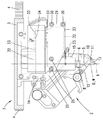
도 1은 한 바람직한 실시 예에 따른 본 발명에 따른 본딩 장치의 본딩 헤드를 도시한 측면도이고,
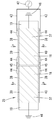
도 2는 도 1의 장치에 포함된 초음파-트랜스듀서를 도 1에 비해 확대 도시한 사시도이며,
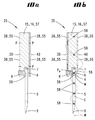
도 3은 도 2에 따른 관찰 방향 Ⅲ으로부터 초음파-트랜스듀서를 바라보고 도시한 측면도이고,
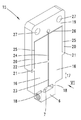
도 4는 도 3에 따른 절단선 Ⅳ-Ⅳ를 따라서 초음파-트랜스듀서를 확대 도시한 단면도이며,
도 5는 도 2에 도시된 초음파-트랜스듀서의 트랜스듀서 바디를 도시한 사시도이고,
도 6은 도 5에 따른 관찰 방향 Ⅵ으로부터 트랜스듀서 바디를 하단부에서 국부적으로 절단하여 도시한 측면도이며,
도 7은 도 3과 대등한 측면도로서, 본 도면에는 상이한 정도로 변형된 피에조 소자의 영역들이 예로서 개략적으로 도시되어 있고,
도 8은 본딩 헤드를 고정시키기 위한 초음파-트랜스듀서의 한 바람직한 고정 상태를 도시한 도 1의 대안적인 실시 예이며,
도 9는 추가의 한 바람직한 실시 예에 따른 본딩 공구가 삽입된 본 발명에 따른 초음파 트랜스듀서의 사시도이고,
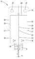
도 10a는 도 9의 절단 평면 Xa를 따라 도 9에 비해 약간 축소시켜서 도시된 단면도이며,
도 10b는 도 10a에 따른 단면도로서, 본 도면에서는 순간적으로 발생하는 진동 형태가 파선 모양의 파동선을 이용해서 개략적으로 도시되어 있다.The invention is described in detail below with reference to the accompanying drawings which show preferred embodiments of the invention.
1 is a side view showing a bonding head of a bonding apparatus according to the present invention in accordance with one preferred embodiment,
FIG. 2 is an enlarged perspective view of the ultrasonic transducer included in the apparatus of FIG. 1 compared to FIG. 1;
FIG. 3 is a side view of the ultrasonic transducer from the viewing direction III according to FIG. 2;
4 is an enlarged cross-sectional view of the ultrasonic transducer along the cutting line IV-IV according to FIG. 3,
FIG. 5 is a perspective view illustrating the transducer body of the ultrasonic transducer illustrated in FIG. 2;
FIG. 6 is a side view of the transducer body locally cut at the lower end from the viewing direction VI according to FIG. 5;
FIG. 7 is a side view equivalent to FIG. 3, in which the regions of the piezo element deformed to different degrees are schematically illustrated as an example,
8 is an alternative embodiment of FIG. 1 showing one preferred fixation state of the ultrasonic transducer for securing the bonding head, FIG.
9 is a perspective view of an ultrasonic transducer according to the present invention with a bonding tool inserted according to a further preferred embodiment,
FIG. 10A is a cross-sectional view showing a slight reduction compared to FIG. 9 along the cutting plane Xa of FIG. 9,
FIG. 10B is a cross-sectional view according to FIG. 10A, in which the instantaneous oscillation pattern is schematically illustrated using a dashed wave line.
우선 본딩 결합을 만들기 위한 본 발명에 따른 본딩 장치 그리고 본 발명에 따른 방법의 한 바람직한 실시 예가 도 1 내지 도 6을 참조해서 기술되며, 이 경우 도 1은 본딩 장치(1)를 단지 이 본딩 장치의 본딩 헤드(2)의 영역에서만 보여주고, 도 2 내지 도 6은 본딩 헤드(2)의 소자들을 확대 도시하여 재현하고 있다. 본딩 헤드(2)는 본딩 장치(1)에 상세하게 도시되지 않은 방식으로, 수직으로 뻗는 회전축(D)을 중심으로 회전 가능하게 고정된 휠(3)의 하부면에 고정되어 있다. 회전을 야기하기 위하여 본 실시 예에서는 커트 아웃 방식으로 도시되어 있고 휠(3)의 외부 톱니 기어에 결합하는 톱니 벨트(4)가 도면에 함께 도시되어 있지 않은 그리고 상기 톱니 벨트가 감긴 상태에서 구동되는 휠에 의해서 회전각에 따라 원하는 구간만큼 이동될 수 있다. 전체 본딩 헤드(2)를 회전축(D)에 대하여 수직인 평면의 다양한 방향으로 측면 이동시키기 위하여 추가로 구동 장치가 제공될 수 있다. 본딩 헤드(2)는 중간 공구 세로축(W)을 따라 연장되는 길게 늘어진 본딩 공구(5)를 포함한다. 상기 본딩 공구는 자체 세로 상단부에서 이 본딩 공구의 샤프트가 상응하는 직경을 갖는 수직 보어(7)(도 6 참조) 안으로 삽입되고, 상기 수직 보어 안에서 클램핑 스크루(8)에 의해 단단히 고정된다. 본딩 공구(5)의 세로 하단부에는 공구 피크(9)가 형성되어 있으며, 상기 공구 피크의 하부 정면에 의해서는 공지된 방식으로 예를 들어 와이어 재료 혹은 스트립 재료로 이루어진 본딩될 전기 도체가 본딩 결합을 위해 제공된 기판의 접촉점, 바람직하게는 회로 콘택의 접촉점을 향하여 압착될 수 있다. 본딩 장소로 와이어 형태의 혹은 스트립 형태의 도체를 가이드 하기 위하여 본딩 장치는 와이어 가이드 장치(10)를 구비하며, 상기 와이어 가이드 장치의 하단부에는 측면이 개방된 가이드 홈(11)이 존재한다. 본딩 공정 동안 특정 시점에 전기 도체를 고정시키고 이 전기 도체에 인장 작용을 가할 수 있기 위하여, 본딩 장치는 도 1의 관찰 방향에서 볼 때 상호 중첩되는 두 개의 클램핑 레그(13)를 구비한 클램핑 장치(12)를 포함하며, 이 경우 상기 클램핑 레그의 자유 단부는 와이어 가이드 장치(10)의 하단부와 공구 피크(9) 사이에 존재한다. 본 명세서에서는 상기 와이어 가이드 장치 및 클램핑 장치의 공지된 기능에 대해서 상세하게 기술할 필요가 없다. 두 개의 소자는 위치 조절될 수 있고, 적합한 수단에 의해서 휠(3) 또는 이 휠에 고정된 단단한 고정 암(14)을 기준으로 각각 원하는 위치에 고정될 수 있다. 공구 수용부(6)는 도 5 및 도 6에 개별적으로 도시된 트랜스듀서 바디(15)의 하단부에 일체형으로 형성되어 있다. 전체적으로 디스크 모양을 갖고 도전성 재료(예컨대 강철)로 제조된 트랜스듀서 바디(15)는 또한 각각 직사각형의 가장자리를 갖는 두 개의 피에조 소자 캐리어(16)를 포함하며, 상기 피에조 소자 캐리어의 주 연장 방향(17)은 기하학적인 회전축(D)에 대하여 그리고 상기 회전축과 일치하는 또는 상기 회전축으로부터 단지 약간만 이격된 공구축(W)에 대하여 평행하게 진행한다. 대략 중앙 하부 에지의 영역에서는 각각의 피에조 소자 캐리어로부터 연결 웨브(18)가 뻗어나오며, 상기 연결 웨브의 하단부에 의해서는 두 개의 피에조 소자 캐리어(16)가 상호 측면으로 이격된 상태로(다시 말해 회전 방향(D)에 대하여 가로로 상호 이격된 상태로) 공구 수용부(6)의 상부면에 결합된다. 또한, 트랜스듀서 바디(15)는 피에조 소자 캐리어(16)를 본딩 헤드(2)에 고정시키기 위한 고정 포크(19)를 포함한다. 이와 같은 고정 목적을 위하여 고정 포크(19)의 고정 암(20)의 세로 하단부(21)가 (주 연장 방향(17)으로의 연장 길이 또는 치수를 기준으로) 피에조 소자 캐리어(16)의 세로 중앙 영역에 있는 각각 하나의 피에조 소자 캐리어(16)에 일체형으로 연결된다. 동일한 높이에는 주 연장 방향(17)으로 평행하게 연장되는 피에조 소자 캐리어(16)가 재료 브리지(22)에 의해 연결되어 있다. 그 외의 상황에서는 두 개의 피에조 소자 캐리어(16)가 도시된 바대로 가늘고 긴 슬롯(23, 24)에 의해 상호 이격되어 있고, 가늘고 긴 슬롯(25, 26)에 의해서는 고정 포크(19)로부터 이격되어 있다. 고정 포크(19)는 자체 상부 영역에 관통 보어(27)를 구비하고, 이 관통 보어에 의해서는 트랜스듀서 몸체(15)가 나사(28)에 의해 플레이트(29)에 단단히 조립된다. 플레이트(29)는 나사(30)에 의해서 프레임 섹션(31)에 일체로 나사 결합되어 있으며, 상기 프레임 섹션은 고정 암(20)과 마찬가지로 휠(3)의 하부면에 고정된 조립 프레임(32)의 구성 부품이다. 도 1에는 상기 프레임이 다른 부품들에 의해 덮여진 상태에서 파선으로 도시되어 있다. 이와 같은 상황에서 조립 프레임(32)은 프레임 횡단면으로 볼 때 감소된 네 개의 섹션(33)을 포함하며, 상기 네 개의 섹션은 비교적 낮은 강성을 갖고, 자체 탄력성 때문에 고정 몸체 링크로서 이용된다. 도 1의 관찰 방향으로부터 볼 때 상기 조립 프레임(32)의 좌측 에지는 고정 암(20)과 마찬가지로 휠(3)에 단단히 고정되어 있는 한편, 관찰 방향으로부터 볼 때 우측에 놓인 프레임 섹션(31)은 예를 들어 본딩 공구(5)를 위로부터 아래로 본딩 장소를 향해 압착하기 위하여 고정 몸체 링크로 인해서 도면에 도시되어 있지 않은 작동기에 의해 프레임 섹션(34)에 가해질 수 있는 파워(F)를 이용하여 상대적으로 소정의 거리만큼 아래로 선회될 수 있다. 파워(F)가 상쇄되면, 프레임 섹션(31)은 탄성적으로 자신의 정지 위치로 되돌아간다.A preferred embodiment of the bonding device according to the invention and the method according to the invention for making a bonding bond is described with reference to FIGS. 1 to 6, in which case FIG. Only the region of the
도 2 내지 도 4는 트랜스듀서 몸체(15)를 도 1의 본딩 헤드에 존재하는 초음파-트랜스듀서(35)의 구성 부품으로서 보여주고 있으며, 상기 초음파-트랜스듀서(35)의 공구 수용부(6) 안에는 재차 본딩 공구(5)가 삽입되어 있다. 예를 들어 도 1 및 도 3으로부터 알 수 있는 사실은, 초음파-트랜스듀서(35)의 주 연장 방향(36)이 본딩 헤드의 기하학적인 회전축(D)에 대하여 평행하게 진행한다는 것이며, 상기 회전축은 본딩 공구의 공구 세로축(W)과 일치하거나 또는 상기 공구 세로축으로부터 단지 약간의 간격만을 두고서 뻗을 수 있다. 상기 예에서 선택된 초음파-트랜스듀서(35)의 실제로 측면 대칭의 구조로 인해 상기 초음파-트랜스듀서의 세로 대칭선(S)도 단지 약간의 측면 오프셋(도 3의 ΔX 참조)을 제외하고는 상기 기하학적인 축(D 및 W)과 일치한다. 도 2 내지 도 4에 확대 도시된 초음파-트랜스듀서(35)는 서로 평행하게 방향 설정된 두 개의 이웃하는 진동 여자기(37)를 포함한다. 각각의 진동 여자기(37)는 두 개 피에조 소자 캐리어(16) 중에 하나의 피에조 소자 캐리어 그리고 주 연장 평면(도 3 참조)으로 직사각형의 가장자리를 갖는 디스크 모양의 각각 두 개의 피에조 소자(38)를 포함하며, 그 중에서 하나의 진동 여자기에 속하는 두 개의 개별 피에조 소자는 관련 피에조 소자 캐리어(16)의 서로 떨어져서 마주하는 그리고 서로 평행한 두 개의 표면(39, 40)에서 전체 접촉면에 걸쳐 평탄하게 접착되어 있다. 도 2 및 도 3은 상기 접촉 평면에서는 (다시 말해 도 3의 투영면에 대하여 평행한 접촉 평면에서는) 피에조 소자 캐리어(16)의 가장자리 또는 형태가 상기 피에조 소자 캐리어 상에 접착된 피에조 소자(38)의 가장자리 또는 형태와 동일하다는 것을 보여주며, 이 경우에는 피팅에 정확하거나 동일 평면에서 이루어지는 접착이 존재한다. 그 결과 피에조 소자(38)의 주 연장 방향(41)도 본딩 헤드(2)의 기하학적인 회전축(D)에 대하여 평행하게 진행하게 된다. 피에조 소자(38)가 선택된 경우에는 디스크 모양의 형태가 언급될 수 있는데, 그 이유는 도 3의 투영면에 대하여 평행하게 놓인 주 연장 평면에서의 상기 피에조 소자의 치수가 도 4의 투영면에 대하여 수직으로 그리고 평행하게 진행하는 평면에서의 두께보다 더 크기 때문이다. 도 4에는 또한 도면 부호 (P)로 표기된 화살표에 의해서 네 개 피에조 소자(38)의 분극 방향이 지시되어 있다. 도면을 통해 알 수 있는 바와 같이 각각의 피에조 소자(38)의 분극 방향(P)은 상기 피에조 소자의 디스크 평면에 대하여 수직으로 연장된다. 동일한 진동 여자기에 속하는 각각 한 쌍의 피에조 소자(38)의 경우에는 분극 방향들이 서로 반대 방향으로 정렬된 상태로 진행한다는 내용도 도시되어 있다. 더 상세하게 말하자면 도 4에 도시된 실시 예에서는 관찰 방향으로부터 볼 때 좌측 진동 여자기(37)의 피에조 소자(38)의 분극 방향(P)이 접촉 표면(39, 40)으로부터 수직으로 멀어지는 방향으로, 다시 말해 외부로 향한다. 그와 달리 관찰 방향으로부터 볼 때 우측에 놓인 진동 여자기(37)의 피에조 소자(38)의 분극 방향(P)은 각각 수직으로 관련 접촉면(39, 40) 쪽으로, 다시 말해 내부로 향한다. 초음파-트랜스듀서(35)로부터 시작되어 서로 병렬 접속된 두 개의 전기 도체(43)가 자체 단부에서 납땜 장소(44)에 의해 동일한 (도 4의 우측에 놓인) 피에조 소자 캐리어(16)의 서로 마주 놓인 두 개의 피에조 소자(38)에 고정됨으로써, 초음파-트랜스듀서(35)는 도시된 실시 예에서 전압원(42)에 연결되어 있다. 도 4에서 사용된 심볼은 교류 전압원이 전압원(42)으로서 사용된다는 사실을 표시해준다. 대안적으로는 상이한 초음파 에너지원(다시 말해 초음파를 형성하기 위한 에너지원), 예를 들어 교류 전류원이 사용될 수도 있다. 추가의 전기 도체(45) 및 상기 도체의 납땜 장소(44)에 의해서는 동일한 평면 안에서 이웃하는 피에조 소자 캐리어 상에 접착된 피에조 소자(38) 쌍이 도전 접속된다. 또한, 본 실시 예에서는 피에조 소자(38)와 피에조 소자 캐리어(16) 간에 이루어지는 각각의 접착 결합도 도전성 결합으로 구현되지만, 그 대신에 비도전성 접착 결합도 가능하다. 피에조 소자 캐리어(16)는 도면 부호 (46)으로 표기된 바와 같이 개별적으로 (또는 공동으로) 접지되어 있다. 이와 같은 방식에 의해서는 전압원(42)이 접속된 경우 네 개의 피에조 소자(38)에는 상기 피에조 소자의 디스크 평면에 대하여 수직으로 각각 양 및 위상 위치와 관련해서 동일한 교류 전압이 인가된다.2 to 4 show the
도 3은 전압원(42)이 스위치-오프 된 상태에서 초음파-트랜스듀서(35) 및 상기 초음파-트랜스듀서(35) 안에 장착된 본딩 공구(5)를 보여주는 한편, 도 7은 특정 시점에 전압원이 스위치-온 된 상태에서, 다시 말해 계산을 위해 예로서 선택된 주파수 및 진폭을 갖는 전기 교류 전압이 인가될 때에 피에조 전기 효과로 인해 발생하는 진동 여자기(37)의 변형, 공구 수용부(6)의 변형 그리고 본딩 공구(5)의 변형을 비교적 개략적으로 예로서 재현하고 있다. 고정 포크(19)의 영역에서도 발생하는 적은 변형들은 도면을 간략하게 할 목적으로 함께 도시하지 않았다. 소위 메인 모드의 전체 변형이 도시되어 있으며, 이 경우 피에조 소자(38)의 표면은 계산의 목적으로 가장자리에 격자 표시된 필드(47)로 세분되었다. 다이어그램 형태의 도시로부터 알 수 있는 사실은, 두 개 고정 암(20)의 종단부(21)를 연결하는 대략 중간의 벨트를 따라서 나타나는 상대적인 위치 편차는 최소이고, 피에조 소자의 두 개의 종단부에서 나타나는 상대적인 위치 편차는 최대라는 것이다. 도 3과 비교할 때 명확하게 알 수 있는 사실은, 관찰 방향으로부터 볼 때 좌측에 있고 피에조 소자 캐리어, 즉 관찰 방향으로부터 볼 때 좌측에 있는 진동 여자기(37)가 그 사이에 제공된 피에조 소자(18)는 인가되는 교류 전압에 의하여 관찰된 시점에서 무전압 정지 상태(도 3 참조)에 비해 해당 주 연장 방향(17 또는 41)으로 연장 또는 길이 단축을 경험하는 한편, 두 개의 피에조 소자(38) 및 피에조 소자 캐리어(16)를 포함하고 우측에 이웃하는 진동 여자기(37)는 상기 시점에 상기 방향으로 길이 증가를 경험한다. 각각의 시점에 모든 피에조 소자에 동일한 전기 전압이 인가됨에도 불구하고 두 개의 쌍은 전술된 상이한 분극 방향으로 인해 절반 위상 길이만큼 상호 변위된 발진 변형 진동을 실행한다. 다양한 해칭에 할당된 숫자 값들은 도 3의 무전압 상태에 대한 상기 영역들의 각각의 상대적인 위치 편차를 비교 값으로서 지시해준다. 두 개의 평행한 진동 여자기(37)의 반대 방향 길이 변경으로 인해 공구 수용부(6)가 도 3의 무전압 정지 상태로부터 출발하여 상기 공구 수용부의 좌측 종단부에서는 상승하고 우측 종단부에서는 하강함으로써, 결과적으로 화살표(48)의 방향으로 회전점(PM) 만큼 비틀림 동작이 나타나게 된다. 상기 회전점(PM)은 공구 수용부 안에 고정된 상기 본딩 공구(5)의 세로 상단부에 있으며, 이 경우 상기 비틀림 동작의 기하학적인 회전축은 상기 회전점(PM)에 의해 도 7의 투영면에 대하여 수직으로 연장되고, 그로 인해 본딩 공구(5)의 길이 파형에 대해서도 수직으로 연장된다. 네 개의 모든 피에조 소자(38)에 동일한 전압이 인가됨에도 불구하고, 두 개의 진동 여자기(37)에서는 상호 반대 방향의 원하는 길이 변경이 이루어지는데, 그 이유는 피에조 소자(38)의 분극 방향(P)이 두 개의 진동 여자기(37) 사이에서는 반대로 방향 설정되어 있기 때문이다. 초음파 범위 안에 있는 주파수를 갖는 교류 전압의 양 및 극성 신호가 - 다시 말해 순시 값이 - 지속적으로 변경되기 때문에, 이와 같은 변경은 또한 상응하는 주파수로 진행되는 상기 진동 여자기(37)의 길이 변경까지도 야기하게 되며, 이 경우에는 다른 무엇보다도 특정 시점에 두 개의 진동 여자기(37)가 동일한 길이를 갖고, 다른 무엇보다도 또 다른 시점에서는 도 7과 반대의 길이 비율이 나타나게 된다. 이와 같은 상황에 의해서는 공구 수용부(6)가 회전점(PM)을 통과하는 회전축만큼 발진 회전 동작으로 여기됨으로써, 결과적으로 상기 회전점(PM)에서는 본딩 공구(5) 안으로 발진 토크(M)가 도입된다. 이와 같은 방식으로 본딩 공구(5)는 도 7에 도시된 바와 같이 휨 진동으로 여기된다. 도 7에는 또한 도 3에서 얻어진, 다시 말해 무전압 정지 상태와 관련이 있는 공구 세로축(W)도 비교의 목적으로 기재되어 있다. 회전 동작의 중심점(P)은 상기 기준선(W) 상에 놓여 있는데, 다시 말하자면 소위 고유 형태의 진동 노드를 의미한다. 그와 달리 공구 피크(9)는 상기 기준선에 대하여 수직으로 명백히 측면으로 편향되는데, 다시 말하자면 소위 진동 루프에 존재한다. 진동 사이클 파형에서 공구 피크(9)는 공구 세로축(W)에 대하여 대체로 수직으로 움직인다. 그럼으로써, 본딩될 전기 도체가 (각각 도시되지 않은) 공구 피크(9)에 의해 기판에 대하여 압착될 때에는 상기 도체도 기판에 대하여 상대적으로 진동으로 변위되며, 이로 인해 본딩 결합이 생성된다.FIG. 3 shows the
도 3 및 도 7에 도시된 실시 예에서는 전압원(42)(도 7에는 개관을 명확히 할 목적으로 도시되어 있지 않음)이 발생되는 교류 전압 및 상기 교류 전압의 전압 주파수와 관련해서 전체 진동 시스템에 매칭됨으로써, 결과적으로 교류 전압이 인가될 때에는 피에조 소자(38)의 기하학적인 주 변형 라인(50)에 상응하는 두 개 진동 여자기(37)의 기하학적인 주 변형 라인(49)이 피에조 소자(38)의 분극 방향(P)에 대하여 가로로 연장된다. 상기 기하학적인 주 변형 라인(49, 50)은 의미상 극성 신호와 무관한 주 변형 방향에 상응한다. 도 7에서 투영면에 대하여 수직으로 회전점(PM)을 통과하는 회전축은 도면 부호 (A)로 표기되어 있고, 상기 회전축(A)을 중심으로 본딩 공구(5) 안으로 도입되는 토크는 도면 부호 (M)으로 표기되어 있다.In the embodiment shown in FIGS. 3 and 7, a voltage source 42 (not shown for clarity in FIG. 7) is generated that matches the overall vibration system with respect to the alternating voltage generated and the voltage frequency of the alternating voltage. As a result, when the alternating voltage is applied, the geometric main strain line 49 of the two
도 8은 전술된 초음파-트랜스듀서(35)를 도 1과 다르게 형성된 조립 프레임(32)과 관련하여 주로 절단된 측면도의 형태로 보여주고 있다. 상기 초음파-트랜스듀서(35)는 단지 암시적으로만 도시되어 있는 결합 부재(51)에 의해서 바람직하게 도 1에 도시된 휠(3)에 설치될 수 있는데, 다시 말하자면 도 1에 도시된 본딩 헤드의 경우에는 그곳에 도시된 조립 프레임(32) 대신에 사용될 수 있다. 하부 크로스 캐리어(53)의 서로를 향하는 단부(52)에서는 조립 프레임(32)이 각각 하나의 피에조 소자 캐리어(16)에 결합된다. 이와 같은 연결은 임의의 방식으로 통합적으로 혹은 일체형으로 또는 다수의 부분으로 (예를 들어 접착, 나사 결합 등에 의해서) 이루어질 수 있다. 연결이 도면 부호 (52)로 표기된 장소에서 일체형으로 구현된 바람직한 경우에는 트랜스듀서 바디(15) 및 프레임(32)으로 이루어진 조합으로서 단 하나의 부품이 사용된다. 도 8의 도시로부터 출발하는 경우에 피에조 소자 캐리어(16)의 영역에 있는 해칭은 프레임(32)의 해칭에 상응하게 선택될 수 있다. 부식이 진동 여자기(37)의 중간 길이 영역에서 각각 재료 브리지(22)의 높이로 이루어짐으로써, 별도의 고정 포크(도 1 참조)도 생략될 수 있다. 하부 크로스 웨브(53)에는 각각 초음파-트랜스듀서(35) 및 수직 캐리어(54)에 인접하고 프레임 횡단면이 축소된 섹션(33)이 쌍으로 제공되어 있으며, 상기 섹션은 고정 몸체 링크로서의 작용을 한다. 이와 같은 방식에 의해서는 특히 심지어 일체형의 트랜스듀서-평행사변형이 형성되며, 상기 일체형의 트랜스듀서-평행사변형은 아래로 향하는 압착력(F)에 의해서 본딩 공구(5)의 소정의 탄성적인 하강을 가능하게 한다. 상기 압착력(F)은 예를 들어 도 8에 도시된 바와 같이 재료 브리지(22)에 작용할 수 있거나 또는 트랜스듀서의 다른 장소에 작용할 수 있다.FIG. 8 shows the above-described
도 9 및 도 10a, 도 10b에는 전술된 도면들과 상이한 본 발명의 추가의 한 바람직한 실시 예에 따른 초음파 트랜스듀서(35)가 도시되어 있다. 이 경우에는 개관을 명확히 하기 위하여 상응하는 특징들과 관련하여 앞에서와 동일한 도면 부호들이 사용되고 있다. 도 9 및 도 10에서는 초음파 트랜스듀서(35) 안에 본딩 공구(5)가 삽입되어 클램핑 스크루(8)에 의해서 그곳에 (도 10a, 도 10b 참조) 고정되어 있다. 초음파 트랜스듀서(35)는 트랜스듀서 바디(15)를 포함하고, 상기 트랜스듀서 바디는 본딩 공구(5)를 수용하기 위한 보어(7) 및 클램핑 스크루(8)를 조이기 위한 나사선 보어 이외에 벌크 재료로 이루어진 직사각형 직육면체로서 구성되어 있다. 도시된 실시 예에서 초음파 트랜스듀서(35)는 총 네 개의 진동 여기 소자(55)를 구비하며, 진동 여기 소자로서는 각각 플레이트 모양의 피에조 소자(38)가 사용된다. 네 개의 피에조 소자(38) 중에 공구 세로축의 방향과 관련하여 연속으로 배치된 두 개의 피에조 소자는 트랜스듀서 바디(15)의 한 측면에 또는 동일한 표면(39)에 평탄하게 접착되어 있으며, 이 경우 본딩 공구(5) 쪽으로 향하는 피에조 소자(38)는 클램핑 스크루(8)를 위한 개구를 갖는다. 상기 표면(39)에 대하여 평행하게 뻗는 마주 놓인 표면(40)에는 투영에 따라 전술된 두 개의 피에조 소자와 일직선으로 두 개의 추가 피에조 소자(38)가 접착되어 있다. 따라서, 트랜스듀서 바디(15)는 도 9 및 도 10의 실시 예에서는 단 하나의 피에조 소자 캐리어(16)를 포함한다. 도 10b는 본딩 공구(5)가 일체로 장착되어 있는 초음파 트랜스듀서(35)가 진동 모드를 갖고, 클램핑이 이루어지는 본딩 공구(5)의 조립점(56)에서 상기 진동 모드의 진동 형태는 가상의 혹은 기하학적인 회전축(A)을 중심으로 이루어지는 회전 방식의 발진 동작을 야기하며, 상기 회전축(A)은 진동 노드에 의하여 상기 조립점(56)의 높이에서 도 10b의 투영면에 대하여 수직으로 뻗는다는 내용을 개략적으로 보여주고 있다. 이와 같은 내용에 따르면 공구 세로축(W)(즉, 본딩 공구의 길이 방향) 및 전술된 회전축(A)에 의해서 설정된 가상의 혹은 기하학적인 기준 평면(E)도 도 10b에서는 그곳의 투영면에 대하여 수직으로 연장된다. 네 개의 모든 진동 여기 소자(55)(즉, 모든 피에조 소자(38))가 기준 평면(E)으로부터 측면으로 또는 피에조 소자(38)의 연장 평면에 대하여 수직인 방향으로 이격된 상태로 배치되어 있음은 명백하다. 상기 네 개의 피에조 소자(38)에 대하여 도 10a는 각각의 분극 방향(P)을 보여준다. 관찰 방향으로부터 볼 때 좌측에서는 상부 피에조 소자(38)가 표면(39)으로부터 멀어지는 분극 방향(P)을 갖는 한편, 하부 피에조 소자(38)는 표면(39) 쪽으로 향하는 분극 방향(P)을 갖는다. 마주 놓인 측에서는 상부 피에조 소자가 표면(40) 쪽으로 향하는 분극 방향(P)을 갖고, 하부 피에조 소자(38)는 표면(40)으로부터 멀어지는 분극 방향(P)을 갖는다. 실시 예에서는 진동 여기 소자로서 피에조 소자가 사용되었기 때문에, 피에조 소자 캐리어(16)로서 사용되는 진동 여기 소자 캐리어(57)가 예컨대 접지되어 피에조 소자(38)의 자유 표면에 상호 동일한 위상의 교류 전압이 인가되면, 이와 같은 상황으로 인해 피에조 소자(38)의 평면 안에서 그리고 그와 더불어 심지어는 공구 세로축의 가상의 연장부에 대하여 대체로 평행하게 시간차를 두고 팽창 및 연장이 발생하게 된다. 도 10b에 기재된 화살표들은 트랜스듀서 바디(15) 쪽으로 향하는 분극 방향(P)을 갖는 두 개의 피에조 소자(38)가 상호 위상 동일한 길이 변경(도시된 시점에서는 다름 아닌 팽창)을 경험한다는 사실 그리고 각각 트랜스듀서 바디(15)로부터 멀어지는 분극 방향을 갖는 나머지 두 개의 피에조 소자(38)는 마찬가지로 쌍으로 동일하지만 두 개의 전술된 피에조 소자(38)에 대하여 반대의 길이 변경(다시 말해 도시된 시점에서는 다름 아닌 연장)을 경험한다는 사실을 설명해주고 있다. 따라서, 기준 평면(E)에 대하여 서로 일직선으로 마주 놓인 각각 두 개의 피에조 소자(38)는 상호 반대의 길이 변경을 경험하게 된다. 동일한 표면(39 및 40)에 접착되어 있는 각각 두 개의 피에조 소자(38)도 상호 반대의 길이 변경을 경험한다. 도 9 및 도 10a, 도 10b에는 피에조 소자(38)를 위한 전압 공급 또는 전류 공급이 함께 도시되어 있지 않다. 그러나 전술된 바와 같이 예를 들어 트랜스듀서 바디가 접지될 수 있고 (또는 다른 전위가 트랜스듀서 바디에 인가될 수 있고) 그리고 모든 피에조 소자(38)의 평탄한 자유 표면에는 예를 들어 상호 도전 결합에 의해서도 상호 동일한 위상의 교류 전압이 인가될 수 있다.9, 10A and 10B show an
트랜스듀서 바디(15)로서는 금속 재료로 이루어진 정방형의 베이스 바디가 사용되며, 상기 베이스 바디의 최장 측은 수직으로 서있는데, 다시 말하자면 공구 세로축(W)의 연장 방향으로 연장된다. 피에조 소자(38)의 전술된 반대 방향으로의 길이 변경으로 인해 트랜스듀서 바디(15)는 휨 진동을 실행하게 되며, 이 경우 "휨 방향"으로의 횡단면, 즉 도 10a, 도 10b의 관찰 방향을 기준으로 할 때 측면 방향 또는 수평 방향으로의 횡단면은 가장 적은 팽창을 갖는다. 바람직하게 그리고 도시된 실시 예에서 트랜스듀서 바디는 도 10b에 도시된 바와 같이 제 2의 휨-고유 모드로 진동한다. 상기 고유 모드는 두 개의 자유 에지에 세 개의 진동 노드를 가지며, 세 개의 진동 노드 중에서 최하부 노드는 본딩 공구(5)의 조립점(56)의 높이에 존재한다. 본 실시 예에서 최하부 노드 아래에는 본딩 공구(5)의 길이에 걸쳐서 마찬가지로 도면 부호 (58)로 표기된 세 개의 추가 진동 노드가 더 분포되어 있다. 따라서, 본딩 공구(5)도 휨 모드를 실행하게 된다. 본딩 공구(5) 및 트랜스듀서 바디(15)는 이 부재들이 (전술된 고유 모드를 위하여) 각각 단독으로 대략 동일한 고유 주파수를 갖도록 기하학적인 치수 및 재료 특성 면에서 상호 매칭되어 있다. 상기 두 개의 부재가 결합되면, 전체 시스템도 상응하는 고유 주파수를 나타낸다. 이 경우에는 (도시된 바와 같이) 본딩 공구(5)의 상부 진동 노드(58) 및 트랜스듀서 바디(15)의 하부 진동 노드(58)가 하나의 공통된 점에 국부적으로 배치되는 것이 바람직하다. 상기 장소 또는 상기 높이에는 클램핑 스크루(8)(본 실시 예에서는 스터드 스크루(stud screw)를 이용한 본딩 공구(5)의 클램핑 상태도 존재한다. 이와 같은 의미에서 본딩 공구(5)는 트랜스듀서 바디(15)의 휨 진동을 균열 없이 재개한다. 본딩 공구(5)를 클램핑 할 수 있기 위하여, 본딩 공구(5)를 위한 팩 홀 모양의 보어(7)는 정확히 트랜스듀서 바디(15)의 휨 평면 중앙에 있지는 않지만, 이 경우 경미한 오프셋은 진동 특성에 대하여 악영향을 거의 미치지 않는다. 그러나 대안적으로는 본딩 공구를 이상적으로 휨 평면 중앙에 배치하는 것도 가능하다. 본 실시 예에서 본딩 공구(5)는 상기 평면에서 휨 평면에 대하여 직각으로 이상적으로 중앙에 배치되어 있다.As the
본 실시 예(도 9 참조)에서 초음파 트랜스듀서(35)를 본딩 헤드에 배치하는 과정 또는 상기 초음파 트랜스듀서를 본딩 헤드에 조립하는 과정은 두 개의 측면 연결 장치(59)에 의해서 이루어질 수 있으며, 상기 연결 장치는 상기 표면(39, 40)에 대하여 직각으로 진행하는 상기 트랜스듀서 바디(15)의 두 개 측면에 서로 마주 놓이도록 설치되어 있다. 상기 연결 장치는 각각 하나의 연결 보어(60)를 구비하며, 본딩 헤드에 조립하기 위한 도면에 함께 도시되지 않은 고정 나사가 상기 연결 보어 안으로 또는 상기 연결 보어를 통하여 관통될 수 있다. 각각의 연결 장치에서 연결 보어(60) 위에 그리고 아래에는 각각 고정 바디 링크(61)(다시 말해 총 네 개의 고정 바디 링크(61)가 존재함)가 존재하며, 이 경우에는 휨 진동을 해제하기 위하여 더 작은 횡단면을 갖는 구역들이 이용된다. 바람직하게 상기 휨 구역들은 트랜스듀서 바디(15)의 정확히 상부 및 중간 진동 노드(58)의 높이에 놓여 있다(도 10b 참조). 이 경우에는 베이스 바디가 전적으로 회전을 실행함으로써, 휨 링크는 이상적으로 작용을 할 수 있게 되고, 이와 같은 방식에 의해 진동 시스템은 자신의 주변으로부터 분리될 수 있다. 대안적으로는, 고정 몸체 링크가 트랜스듀서 바디(15)의 상부 및 하부 진동 노드(58)의 높이에 있거나 또는 트랜스듀서 바디(15)의 중간 및 하부 진동 노드(58)의 높이에 있는 변형 예도 가능하다. 고정 바디 링크(61)의 상부 및 하부에는 트랜스듀서 바디(15)와 연결 장치(59)의 연결 장소도 존재한다. 바람직하게 상기 연결 장치(59)는 트랜스듀서 바디(15)와 일체로 또는 통합적으로 구현되어 있는데, 다시 말하자면 지지부와 베이스 바디가 하나의 부분으로 형성되어 있지만 이와 다른 형상도 생각할 수 있다.In the present embodiment (see FIG. 9), the process of disposing the
도 9 및 도 10에 도시된 실시 예에서도 초음파 진동은 얇은 피에조 플레이트에 의해서 발생된다. 이 경우에도 분극 방향(P)에 대하여 그리고 전기장에 대하여 직각인 진동 방향이 이용된다. 전술된 바와 같이, 베이스 바디의 진동 모드(특별히 제 2 휨 모드)를 이상적으로 여기하기 위하여 총 네 개의 피에조 소자(38)가 사용되며, 이 경우 각각 대각으로 마주 놓인 소자들은 서로 동일한 방식으로 동시에 팽창 또는 연장된다. 예를 들어 표면(39)에 접착된 두 개의 피에조 소자(38)를 생략하거나 또는 표면(40)에 접착된 두 개의 피에조 소자(38)를 생략함으로써 변형이 이루어질 수 있다. 이와 같은 변형에 의해서 생성되는 변형 실시 예에서도 트랜스듀서 바디(15)는 여전히 제 2 휨 모드로 여기된다. 다른 한 가지 변형 예는 예를 들어 도 10a, 도 10b를 참조하여 두 개의 상부 피에조 소자(38)가 생략되거나 또는 두 개의 하부 피에조 소자(38)가 생략됨으로써 가능하다. 이와 같은 배열 상태에서는 트랜스듀서 바디(15)가 제 1 휨 모드로 여기되며, 이 경우에도 매칭이 적합한 경우에는 본딩 공구(5) 안으로 발진 토크가 도입된다. 그와 유사하게 도 9 및 도 10으로부터 출발하면, 트랜스듀서 바디(15)를 더 높은 휨 모드로 여기하기 위하여 공구 길이 방향(W)의 연장부 안에 연속으로 배치되는 하나 또는 다수의 추가 피에조 소자(38)가 각각의 표면(39, 40)에 더 제공되는 실시 예도 가능하다.9 and 10, the ultrasonic vibration is generated by the thin piezo plate. Also in this case, a vibration direction perpendicular to the polarization direction P and to the electric field is used. As described above, a total of four
공개된 모든 특징들은 (그 자체로) 본 발명에 중요하다. 따라서, 해당/첨부된 우선권 서류들(예비 출원서의 사본)의 특징들을 본 출원서의 청구범위에 함께 수용할 목적으로도, 상기 우선권 서류들의 공개 내용은 본 출원서의 공개 범위에 완전히 포함된다.
All features disclosed are (in themselves) important to the invention. Accordingly, even for the purpose of accommodating the features of the corresponding / attached priority documents (copy of the preliminary application) together with the claims of this application, the disclosure of such priority documents is fully incorporated into the disclosure scope of this application.
Claims (33)
상기 초음파 트랜스듀서(35)의 주(主) 연장 방향(36) 및/또는 상기 초음파 트랜스듀서의 연장 방향이 최소 관성 능률(minimum moment of inertia)의 축의 방향으로 상기 본딩 헤드(2)의 기하학적인 회전축(D)에 대하여 평행하게 연장되는 것을 특징으로 하는, 본딩 장치.In particular a bonding device for making a bonding bond between an electrical conductor made of a wire material or a strip material and in particular a contact point of a substrate, such as an electrical circuit, in which the bonding device can in particular rotate about a geometric vertical axis of rotation (D). In the bonding apparatus, provided with a head (2), the bonding head is provided with a bonding tool (5) and an ultrasonic transducer (35) for ultrasonic-vibrating excitation of the bonding tool (5).
The main extension direction 36 of the ultrasonic transducer 35 and / or the direction of extension of the ultrasonic transducer is the geometry of the bonding head 2 in the direction of the axis of the minimum moment of inertia. Bonding device, characterized in that extending parallel to the axis of rotation (D).
작동 중에, 특히 교류 전압이 인가될 때에 상기 진동 여자기(37)의 주 변형 방향 및/또는 상기 피에조 소자(38)의 주 변형 방향이 상기 피에조 소자(38)의 분극 방향(P)에 대하여 가로로 연장되도록 상기 초음파 에너지원, 특히 전압원(42), 특히 상기 전압원의 주파수가 적응되거나 또는 조절될 수 있는 것을 특징으로 하는, 초음파 트랜스듀서.In particular an ultrasonic transducer for a bonding device for ultrasonic-vibrating excitation of a bonding tool of a bonding device, wherein said ultrasonic transducer comprises at least one vibrating exciter and said vibrating exciter comprises at least one piezo element. An ultrasonic transducer provided with a voltage source for applying an energy source, in particular an electrical alternating voltage, to said piezo element,
During operation, in particular, when an alternating voltage is applied, the main deformation direction of the vibration exciter 37 and / or the main deformation direction of the piezo element 38 is transverse to the polarization direction P of the piezo element 38. Ultrasonic transducer, characterized in that the frequency of the ultrasonic energy source, in particular the voltage source (42), in particular the voltage source, can be adapted or adjusted to extend to
작동 중에 두 개 진동 여자기(37)의 주 변형 방향이 서로 평행하게 또는 대체로 평행하게 진행하여 상기 두 개 진동 여자기의 시간에 따라 변동되는 변형들이 서로 위상 변위된 상태로, 바람직하게는 절반 주기만큼 위상 변위된 상태로 만료되는 방식으로, 하나 또는 다수의 초음파 에너지원, 특히 전압원(42) 또는 전압원들, 특히 주파수 및/또는 위상 위치가 상기 초음파 트랜스듀서(35) 및 본딩 공구(5)에 매칭되거나 매칭될 수 있는 것을 특징으로 하는, 초음파 트랜스듀서.An ultrasonic transducer for ultrasonic-vibrating excitation of a bonding tool, the ultrasonic transducer comprising two or more vibration excitators coupled to a tool receptacle with the ultrasonic transducers spaced apart from each other, the at least one for supplying power to the vibration exciter An ultrasonic transducer, in particular provided with at least one voltage source for applying an electrical alternating voltage to the vibrating exciter,
During operation, the main deformation directions of the two vibrating exciters 37 run in parallel or substantially parallel to each other, so that the deformations varying with time of the two vibrating exciters are phase shifted from each other, preferably in a half cycle. One or more ultrasonic energy sources, in particular voltage source 42 or voltage sources, in particular frequency and / or phase positions, in such a way that they expire in a phase shifted state by the ultrasonic transducer 35 and the bonding tool 5. An ultrasonic transducer, characterized in that it can be matched or can be matched.
상기 본딩 장치의 본딩 헤드에 제 4 항에 따른 초음파 트랜스듀서가 제공된 것을 특징으로 하는, 본딩 장치.In particular a bonding device for making a bonding bond between an electrical conductor made of a wire material or a strip material and in particular a contact point of a substrate such as an electrical circuit, the bonding device having a bonding head, the bonding head having a bonding housed in a bonding receptacle. In a bonding apparatus, a tool is provided, in which a wedge is used, in particular as the bonding tool,
Bonding device, characterized in that the ultrasonic transducer according to claim 4 is provided in the bonding head of the bonding device.
상기 초음파 트랜스듀서(35)의 기하학적인 세로 대칭축(S)이 특히 회전축(D)에서 또는 상기 회전축으로부터 약간의 간격을 두고서 상기 본딩 헤드(2)의 기하학적인 회전축(D)에 대하여 평행하게 연장되고, 그리고/또는 특히 세로 중심선(W)에서 또는 상기 세로 중심선으로부터 약간의 간격을 두고서 상기 본딩 공구(5)의 세로 중심선(W)에 대하여 평행하게 연장되는 것을 특징으로 하는, 본딩 장치.The method according to any one of the preceding claims,
The geometric longitudinal axis of symmetry S of the ultrasonic transducer 35 extends in parallel with the geometric axis of rotation D of the bonding head 2, in particular at the axis of rotation D or at some distance from the axis of rotation. And / or extend in parallel with the longitudinal centerline (W) of the bonding tool (5), in particular at a longitudinal centerline (W) or at some distance from the longitudinal centerline.
상기 초음파 트랜스듀서(35)가 적어도 하나의 진동 여자기(37)를 포함하고, 각각의 진동 여자기(37)가 적어도 하나의 피에조 소자(38)를 포함하며, 이때 각각의 피에조 소자(38)는 상기 본딩 헤드(2)의 기하학적인 회전축(D)에 대하여 평행하게 연장되는 주 연장 방향(41)을 갖는 것을 특징으로 하는, 본딩 장치.The method according to any one of the preceding claims,
The ultrasonic transducer 35 comprises at least one vibrating exciter 37 and each vibrating exciter 37 comprises at least one piezo element 38, wherein each piezo element 38 is provided. Bonding device, characterized in that it has a main extension direction (41) extending parallel to the geometric axis of rotation (D) of the bonding head (2).
교류 전압이 인가될 때에 상기 진동 여자기(37)의 주 변형 방향 및/또는 상기 피에조 소자(38)의 주 변형 방향이 적어도 대체로 상기 피에조 소자(38)의 주 연장 방향(41)으로 연장되도록 초음파 에너지원, 특히 전압원(42), 특히 상기 전압원의 전압 주파수가 적응되거나 조절될 수 있는 것을 특징으로 하는, 본딩 장치.The method according to any one of claims 2, 3, and 7,
Ultrasonic waves such that when the alternating voltage is applied, the main deformation direction of the vibration exciter 37 and / or the main deformation direction of the piezo element 38 extends at least substantially in the main extension direction 41 of the piezo element 38. Bonding device, characterized in that the energy source, in particular the voltage source (42), in particular the voltage frequency of the voltage source can be adapted or adjusted.
상기 공구 수용부(6)의 회전점(P)이 위치에 따라 상기 본딩 공구(5)의 한 진동 노드와 일치하도록, 상기 초음파-트랜스듀서(35)에 의해 진동으로 여기될 수 있는 본딩 헤드(2) 소자들의 형상 및 교류 전압, 특히 상기 교류 전압의 주파수가 상호 매칭되거나 또는 매칭될 수 있는 것을 특징으로 하는, 본딩 장치.8. The method according to any one of claims 4 to 7,
A bonding head that can be excited with vibration by the ultrasonic transducer 35 such that the rotation point P of the tool receiving portion 6 coincides with one vibration node of the bonding tool 5 according to the position ( 2) A bonding device, characterized in that the shape of the elements and the alternating voltage, in particular the frequency of the alternating voltage, can be matched or matched with each other.
교류 전압이 인가될 때에 진동하고 초음파-트랜스듀서(35), 공구 수용부(6) 및 공구(5)를 포함하는 부품 그룹의 공진 주파수, 특히 가장 낮은 공진 주파수에 적어도 대략 상응하도록 상기 초음파 에너지원의 주파수, 특히 전압원에서의 전압 주파수가 사전에 선택되거나 또는 조절될 수 있는 것을 특징으로 하는, 본딩 장치.The method according to any one of the preceding claims,
The ultrasonic energy source oscillates when an alternating voltage is applied and at least approximately corresponds to the resonant frequency, in particular the lowest resonant frequency, of the group of parts comprising the ultrasonic transducer 35, the tool receiver 6, and the tool 5. Bonding device, characterized in that the frequency of, in particular the voltage frequency at the voltage source can be selected or adjusted in advance.
하나 또는 다수의 피에조 소자(38)가 각각 직사각형의 가장자리를 갖는 디스크의 형태를 갖추고 있으며, 이때 각각의 피에조 소자(38)의 분극 방향(P)은 상기 디스크 평면에 대하여 가로로 방향 설정된 것을 특징으로 하는, 본딩 장치.The method according to any one of the preceding claims,
One or more piezo elements 38 each have the form of a disk with a rectangular edge, wherein the polarization direction P of each piezo element 38 is oriented horizontally with respect to the disk plane. Bonding device.
상기 초음파-트랜스듀서(35)가 서로 평행하게 배치된 두 개 이상의 진동 여자기(37)를 포함하며, 이때 각각의 진동 여자기(37)는 하나의 피에조 소자 캐리어(16) 그리고 동일한 형태의 두 개의 피에조 소자(38)를 포함하고, 상기 두 개의 피에조 소자는 상기 피에조 소자 캐리어(16)의 상호 떨어져서 마주하는 그리고 서로 평행한 두 개의 표면(39, 40)에 평탄하게 고정되고, 바람직하게는 상기 표면에 평탄하게 접착되는 것을 특징으로 하는, 본딩 장치.The method according to any one of the preceding claims,
The ultrasonic transducers 35 comprise two or more vibration excitations 37 arranged in parallel with each other, wherein each vibration excitation 37 has one piezo element carrier 16 and two of the same type. Two piezo elements 38, the two piezo elements being flatly fixed to two surfaces 39, 40 facing each other and parallel to each other of the piezo element carrier 16, preferably Bonding device, characterized in that it is adhered evenly to the surface.
동일한 진동 여자기(37)의 구성 부품인 피에조 소자들(38)의 분극 방향(P)이 서로 반대 방향으로 정렬된 상태로 진행하는 것을 특징으로 하는, 본딩 장치.The method according to any one of the preceding claims,
Bonding device, characterized in that the polarization direction (P) of the piezo elements (38), which are components of the same vibration exciter (37), proceed in a state aligned in opposite directions to each other.
상기 두 개 피에조 소자 캐리어(16) 중 하나의 피에조 소자 캐리어에 제공된 두 개 피에조 소자(38)의 분극 방향(P)은 상기 피에조 소자 캐리어(16)로부터 멀어지도록 방향 설정되어 있으며, 그리고 두 개 피에조 소자 캐리어(16) 중 다른 하나의 피에조 소자 캐리어에 제공된 두 개 피에조 소자(38)의 분극 방향(P)은 상기 피에조 소자 캐리어(16) 쪽을 향하도록 설정된 것을 특징으로 하는, 본딩 장치.The method according to claim 12 or 13,
The polarization direction P of the two piezo elements 38 provided in one piezo element carrier of the two piezo element carriers 16 is oriented away from the piezo element carrier 16, and the two piezos Bonding device, characterized in that the polarization direction (P) of two piezo elements (38) provided in the other one of the element carriers (16) is set toward the piezo element carrier (16).
상기 피에조 소자(38)는 상기 피에조 소자 캐리어(16)로부터 다른 쪽을 향하는 자신의 자유 표면에서 초음파 에너지원, 특히 전압원(42)에 연결되며, 그리고 상기 피에조 소자 캐리어(16)는 접지되는 것을 특징으로 하는, 본딩 장치.The method according to any one of claims 12 to 14,
The piezo element 38 is connected to an ultrasonic energy source, in particular a voltage source 42 at its free surface facing away from the piezo element carrier 16, and the piezo element carrier 16 is grounded. Bonding apparatus.
특히 모든 피에조 소자(38)의 연결 라인(43, 45)이 서로 병렬 접속됨으로써, 상기 초음파 에너지원, 특히 전압원(42)은 모든 피에조 소자(38)에 상호 위상 동일한 전기 교류 전압을 제공할 수 있도록 적응된 것을 특징으로 하는, 본딩 장치.The method according to any one of claims 2, 3 and 6 to 15,
In particular, the connection lines 43, 45 of all piezoelectric elements 38 are connected in parallel to each other so that the ultrasonic energy source, in particular the voltage source 42, can provide an electrical alternating voltage which is in phase with each piezoelectric element 38. Bonding device, characterized in that adapted.
상기 본딩 공구가 기하학적인 공구 세로축(W)을 포함하고, 상기 공구 세로축은 피에조 소자(38)의 주 연장 방향(41)에 대하여 평행하게 그리고/또는 상기 본딩 헤드(2)의 기하학적인 회전축(D)을 따라서 연장되는 것을 특징으로 하는, 본딩 장치.The method according to any one of claims 2, 3 and 6 to 16,
The bonding tool comprises a geometric tool longitudinal axis W, the tool longitudinal axis parallel to the main direction of extension 41 of the piezo element 38 and / or the geometric axis of rotation D of the bonding head 2. Bonding device, characterized in that extending along).
상기 두 개의 피에조 소자 캐리어(16)는 일체형 트랜스듀서 바디(15)의 구성 부품이고, 상기 트랜스듀서 바디에는 특히 공구 수용부(6)도 일체형으로 제공되는 것을 특징으로 하는, 본딩 장치.18. The method according to any one of claims 12 to 17,
The two piezo element carriers (16) are components of an integral transducer body (15), in which the tool body (6) is also provided in one piece, in particular a bonding device.
상기 트랜스듀서 바디(15)가 고정 포크(19)를 포함하고, 상기 고정 포크의 고정 암(20)의 종단부(21)는 피에조 소자 캐리어(16)의 세로 중앙 영역에서 각각 하나의 피에조 소자 캐리어(16)에 결합하는 것을 특징으로 하는, 본딩 장치.The method of claim 18,
The transducer body 15 comprises a stationary fork 19, wherein the end portions 21 of the stationary arm 20 of the stationary fork each have one piezo element carrier in the longitudinal center region of the piezo element carrier 16. Bonding apparatus (16).
특히 본딩 공구(5)가 공구 수용부(6)에 장착되도록 구성된 초음파 트랜스듀서(35)는 진동 모드를 포함하고, 상기 진동 모드의 진동 형태는 본딩 공구(5)의 장착점(56)에서 적어도 하나의 회전축(A)을 중심으로 이루어지는 회전 방식의 발진 동작을 야기하거나 또는 회전 및 병진 동작을 위한 조합된 발진 여기를 야기하는 것을 특징으로 하는, 초음파 트랜스듀서.An ultrasonic transducer comprising at least one transducer body 15 and at least one vibrating excitation element 55, the vibrating excitation element being configured to transmit vibrations generated by itself to the transducer body 15. In an ultrasonic transducer, connected to the transducer body 15 in a suitable manner,
In particular, the ultrasonic transducer 35 in which the bonding tool 5 is configured to be mounted to the tool receiving portion 6 comprises a vibration mode, the vibration mode of which is at least one at the mounting point 56 of the bonding tool 5. Ultrasonic transducer, characterized in that it causes the oscillation operation of the rotation scheme made around the axis of rotation (A) of the or cause a combined oscillation excitation for the rotation and translation operation.
상기 진동 여기 소자(55)가 트랜스듀서 바디(15)에 파워 결합 방식으로 그리고/또는 형상 결합 방식으로 그리고/또는 재료 결합 방식으로 고정되는 것을 특징으로 하는, 초음파 트랜스듀서.The method of claim 20,
Ultrasonic transducer, characterized in that the vibration excitation element (55) is fixed to the transducer body (15) in a power coupling manner and / or shape coupling manner and / or material coupling manner.
상기 발진 회전 동작은 상기 본딩 공구(5)의 세로축(W)에 대하여 수직인 또는 적어도 대체로 수직인 적어도 하나의 기하학적인 회전축(A)을 중심으로 이루어지도록 방향 설정된 것을 특징으로 하는, 초음파 트랜스듀서.The method of claim 20,
The oscillating rotational operation is characterized in that it is oriented about at least one geometric axis of rotation (A) perpendicular or at least substantially perpendicular to the longitudinal axis (W) of the bonding tool (5).
상기 본딩 공구(5)의 기하학적인 세로축(W) 또는 상기 세로축에 대하여 평행한 기하학적인 선에 의해서 그리고 전술된 회전축(A)에 의해서 기하학적인 기준 평면(E)이 설정되며, 상기 적어도 하나의 진동 여기 소자(55)는 상기 기준 평면(E)으로부터 측면으로 이격된 상태로 배치되며, 그리고 상기 진동 여기 소자(55)에 의해서 트랜스듀서 바디(15)에 가해지는 파워는 본딩 공구(5)의 세로축(W)의 방향으로 혹은 대체로 이 방향으로 작용하는 것을 특징으로 하는, 초음파 트랜스듀서.The method according to any one of claims 20 to 22,
The geometric reference plane E is set by the geometric longitudinal axis W of the bonding tool 5 or by a geometric line parallel to the longitudinal axis and by the above-described rotation axis A, wherein the at least one vibration The excitation element 55 is disposed laterally spaced apart from the reference plane E, and the power applied to the transducer body 15 by the vibration excitation element 55 is the longitudinal axis of the bonding tool 5. An ultrasonic transducer, which acts in the direction of (W) or generally in this direction.
상기 기준 평면(E)으로부터 측면으로 이격된 두 개 이상의 진동 여기 소자(55)가 존재하고, 상기 진동 여기 소자들은 상기 기준 평면(E)을 기준으로 서로 마주 보도록 배치되는 것을 특징으로 하는, 초음파 트랜스듀서.The method of claim 23,
There are two or more vibration excitation elements 55 laterally spaced apart from the reference plane E, and the vibration excitation elements are arranged to face each other with respect to the reference plane E. Producer.
특히 상기 기준 평면(E)의 동일한 측 또는 상이한 측에 배치된 상기 진동 여기 소자(55)가 상호 180°만큼 위상 이동된 진동을 행사할 수 있도록 상기 진동 여기 소자(55)에 연결된 하나 또는 다수의 에너지원, 특히 하나 또는 다수의 전압원이 상기 진동 여기 소자(55)에 전력을 공급하기 위하여 제공되는 것을 특징으로 하는, 초음파 트랜스듀서.The method according to any one of claims 20 to 24,
In particular one or more energies connected to the vibration excitation element 55 such that the vibration excitation elements 55 arranged on the same side or on different sides of the reference plane E can exert a phase shifted oscillation by 180 °. An ultrasonic transducer, characterized in that a circle, in particular one or several voltage sources, is provided for powering the vibration excitation element (55).
상기 기준 평면(E)의 각각의 측에 두 개 이상의 진동 여기 소자(55)가 배치되어 있으며, 이때 상기 기준 평면(E)의 양측에 배치된 진동 여기 소자(55)는 서로 쌍으로 마주 놓이고, 상기 기준 평면(E)의 동일한 측에서 서로 이웃하는 진동 여기 소자(55)는 이 진동 여기 소자가 상호 180°만큼 위상 이동된 진동을 행사할 수 있도록 상기 에너지원(들)에 연결되며, 그리고 상기 기준 평면(E)을 기준으로 서로 쌍으로 마주 놓이는 진동 여기 소자(55)는 이 진동 여기 소자가 상호 180°만큼 위상 이동된 진동을 행사할 수 있도록 상기 에너지원(들)에 연결되는 것을 특징으로 하는, 초음파 트랜스듀서.The method according to any one of claims 23 to 25,
Two or more vibration excitation elements 55 are disposed on each side of the reference plane E, and the vibration excitation elements 55 disposed on both sides of the reference plane E face each other in pairs. , The oscillating excitation elements 55 neighboring each other on the same side of the reference plane E are connected to the energy source (s) such that the oscillating excitation elements exert a phase shifted oscillation by 180 ° with each other, and the Vibration excitation elements 55 which are paired with each other with respect to the reference plane E are connected to the energy source (s) such that the vibration excitation elements can exert a phase shifted oscillation by 180 ° to each other. , Ultrasonic transducer.
상기 기준 평면(E)의 동일한 측에 배치된 각각 두 개 이상의 진동 여기 소자(55)는 상기 본딩 공구(5)의 기하학적인 세로축(W)의 방향으로 연속으로 배치되는 것을 특징으로 하는, 초음파 트랜스듀서.27. The method according to any one of claims 23 to 26,
Two or more vibrating excitation elements 55 arranged on the same side of the reference plane E are arranged successively in the direction of the geometric longitudinal axis W of the bonding tool 5. Producer.
상기 트랜스듀서 바디(15)는 단 하나의 진동 여기 소자 캐리어(57)를 포함하고, 상기 진동 여기 소자(55), 특히 모든 진동 여기 소자(55)는 진동 여자기를 형성하면서 상호 떨어져서 마주하는 상기 진동 여기 소자 캐리어(57)의 두 개의 표면(39, 40)에 배치되며, 그리고 상기 진동 여기 소자 캐리어(57)는 적어도 대체로 직사각형 직육면체의 형태 또는 직사각형 플레이트의 형태를 갖는 것을 특징으로 하는, 초음파 트랜스듀서.The method according to any one of claims 20 to 27,
The transducer body 15 comprises only one vibration excitation element carrier 57, wherein the vibration excitation element 55, in particular all vibration excitation elements 55, face each other away from each other while forming an oscillation exciter. Ultrasonic transducers, which are arranged on two surfaces 39, 40 of the excitation element carrier 57, wherein the vibrating excitation element carrier 57 is at least generally in the form of a rectangular cuboid or in the form of a rectangular plate. .
진동 여기 소자(55)로서 각각 적어도 하나의 피에조 소자(38)가 제공되며, 그리고 상기 트랜스듀서 바디(15)는 전체 피에조 소자를 지지하는 단 하나의 피에조 소자 캐리어(16)를 포함하고, 상기 피에조 소자 캐리어는 적어도 대체로 직사각형 직육면체의 형태 또는 직사각형 플레이트의 형태를 갖는 것을 특징으로 하는, 초음파 트랜스듀서.The method according to any one of claims 20 to 28,
Each oscillating excitation element 55 is provided with at least one piezo element 38, and the transducer body 15 comprises only one piezo element carrier 16 which supports the entire piezo element. The device carrier, characterized in that at least generally in the form of a rectangular cuboid or in the form of a rectangular plate.
본딩 공구를 제공하는 단계를 포함하고,
상기 본딩 공구를 초음파-진동 여기하기 위한 초음파 트랜스듀서를 제공하는 단계를 포함하며, 이때 상기 초음파 트랜스듀서는 적어도 하나의 진동 여자기를 포함하고, 상기 진동 여자기는 적어도 하나의 피에조 소자를 포함하며,
상기 피에조 소자에 전력을 공급하기 위한 초음파 에너지원, 특히 상기 피에조 소자에 전기 교류 전압을 인가하기 위한 전압원을 제공하는 단계를 포함하고, 그리고
본딩 공구를 이용해서 접촉점을 향하여 본딩될 전기 도체를 압착하는 동안 상기 본딩 공구를 진동 여기하는 단계를 포함하는, 본딩 결합을 만들기 위한 방법에 있어서,
상기 본딩 공구(5)의 진동 여기를 위하여 작동 중에 상기 진동 여자기(37)의 기하학적인 주 변형 라인(49) 및/또는 상기 피에조 소자(38)의 주 변형 라인(50)이 상기 피에조 소자(38)의 분극 방향(P)에 대하여 가로로 연장되도록 초음파 에너지원, 특히 전압원(42), 특히 상기 전압원의 초음파 주파수를 선택하거나 또는 조절하는 것을 특징으로 하는, 본딩 결합을 만들기 위한 방법.As a method for making a bonding bond between an electrical conductor, in particular a wire material or strip material, and in particular a contact point of a substrate, such as an electrical circuit,
Providing a bonding tool,
Providing an ultrasonic transducer for ultrasonic-vibrating excitation of the bonding tool, wherein the ultrasonic transducer includes at least one vibrating exciter, the vibrating exciter including at least one piezo element,
Providing an ultrasonic energy source for supplying power to said piezo element, in particular a voltage source for applying an electrical alternating voltage to said piezo element, and
A method for making a bonding engagement, comprising vibrating excitation of a bonding tool while pressing an electrical conductor to be bonded toward a contact point using a bonding tool.
For the purpose of vibration excitation of the bonding tool 5, during operation the geometric main strain line 49 of the vibration exciter 37 and / or the main strain line 50 of the piezo element 38 may be used. And selecting or adjusting the ultrasonic energy source, in particular the voltage source (42), in particular the ultrasonic frequency of said voltage source, so as to extend transversely with respect to the polarization direction (P) of (38).
본딩 공구를 초음파-진동 여기하기 위하여 본딩 공구 및 초음파 트랜스듀서를 제공하는 단계를 포함하고,
본딩 공구를 이용해서 접촉점을 향하여 본딩될 전기 도체를 압착하는 동안 상기 본딩 공구를 진동 여기하는 단계를 포함하는, 본딩 결합을 만들기 위한 방법에 있어서,
공구 수용부(6)에서 본딩 공구(5)를 진동 여기하기 위하여 공구 세로축(W)에 대하여 가로로 뻗는 기하학적인 회전축(A)을 갖는 발진 토크(M)를 상기 본딩 공구(5) 안으로 도입하거나, 또는 공구 수용부(6)에서 본딩 공구(5)를 진동 여기하기 위하여 발진 토크(M) 및 병진 운동 방식의 발진 여기를 상기 본딩 공구(5) 안으로 도입하는 것을 특징으로 하는, 본딩 결합을 만들기 위한 방법.As a method for making a bonding bond between an electrical conductor, in particular a wire material or strip material, and in particular a contact point of a substrate, such as an electrical circuit,
Providing a bonding tool and an ultrasonic transducer to ultrasonically vibrate the bonding tool,
A method for making a bonding engagement, comprising vibrating excitation of a bonding tool while pressing an electrical conductor to be bonded toward a contact point using a bonding tool.
An oscillation torque M having a geometric axis of rotation A extending transversely with respect to the tool longitudinal axis W in order to vibrate the bonding tool 5 at the tool receiving portion 6 or into the bonding tool 5, or Or alternatively introducing an oscillating torque M and an oscillating excitation in a translational manner into the bonding tool 5 for vibrating excitation of the bonding tool 5 at the tool receiving portion 6. Way.
본딩 공구(5)의 한 진동 노드의 장소에서 상기 발진 토크(M)를 상기 본딩 공구 안으로 도입하는 것을 특징으로 하는, 본딩 결합을 만들기 위한 방법.The method of claim 31, wherein
A method for making a bonding engagement, characterized in that the oscillating torque (M) is introduced into the bonding tool at the location of one vibration node of a bonding tool (5).
전술한 항들 중 어느 한 항 또는 다수의 항에 따른 본딩 장치(1)를 사용하는 것을 특징으로 하는, 본딩 결합을 만들기 위한 방법.32. The method of claim 30 or 31 wherein
A method for making a bonding bond, characterized in that it uses a bonding device (1) according to any of the preceding claims.
Applications Claiming Priority (4)
| Application Number | Priority Date | Filing Date | Title |
|---|---|---|---|
| DE102008037450.4 | 2008-10-14 | ||
| DE102008037450 | 2008-10-14 | ||
| DE102009003312.2 | 2009-01-06 | ||
| DE102009003312A DE102009003312A1 (en) | 2008-10-14 | 2009-01-06 | Bonding device, ultrasonic transducer and bonding method |
Publications (1)
| Publication Number | Publication Date |
|---|---|
| KR20110084899A true KR20110084899A (en) | 2011-07-26 |
Family
ID=41821369
Family Applications (1)
| Application Number | Title | Priority Date | Filing Date |
|---|---|---|---|
| KR1020117010160A KR20110084899A (en) | 2008-10-14 | 2009-10-07 | Bonding device, ultrasonic transducer, and bonding method |
Country Status (9)
| Country | Link |
|---|---|
| US (1) | US8434659B2 (en) |
| EP (1) | EP2344295B1 (en) |
| JP (1) | JP5683470B2 (en) |
| KR (1) | KR20110084899A (en) |
| CN (1) | CN102186620B (en) |
| DE (1) | DE102009003312A1 (en) |
| MY (1) | MY158655A (en) |
| TW (1) | TWI519017B (en) |
| WO (1) | WO2010043517A2 (en) |
Cited By (1)
| Publication number | Priority date | Publication date | Assignee | Title |
|---|---|---|---|---|
| KR20130020549A (en) * | 2011-08-19 | 2013-02-27 | 주식회사 엘지화학 | Ultrasonic welding machine and method of aligning an ultrasonic welding horn relative to an anvil |
Families Citing this family (11)
| Publication number | Priority date | Publication date | Assignee | Title |
|---|---|---|---|---|
| US20120109207A1 (en) * | 2010-10-29 | 2012-05-03 | Warsaw Orthopedic, Inc. | Enhanced Interfacial Conformance for a Composite Rod for Spinal Implant Systems with Higher Modulus Core and Lower Modulus Polymeric Sleeve |
| DE102014109630A1 (en) | 2014-07-09 | 2016-01-14 | Hesse Gmbh | Apparatus for making a bond and transducer therefor |
| DE102015120824A1 (en) * | 2015-12-01 | 2017-06-01 | Hesse Gmbh | Operating method for an ultrasonic wire bonder |
| US10052714B2 (en) * | 2016-10-14 | 2018-08-21 | Sonics & Materials, Inc. | Ultrasonic welding device with dual converters |
| JP6483079B2 (en) * | 2016-12-13 | 2019-03-13 | 本田技研工業株式会社 | Electrical conductor joining method |
| US10381321B2 (en) * | 2017-02-18 | 2019-08-13 | Kulicke And Soffa Industries, Inc | Ultrasonic transducer systems including tuned resonators, equipment including such systems, and methods of providing the same |
| CN108555429B (en) * | 2018-05-16 | 2023-06-20 | 华侨大学 | Large-range continuous ultrasonic welding device for metal foil |
| TWI741705B (en) | 2020-07-28 | 2021-10-01 | 國立中興大學 | Power supply outside the spindle |
| CN112427281B (en) * | 2020-09-18 | 2022-05-24 | 集美大学 | Complex frequency ultrasonic vibration processing device |
| US11937979B2 (en) * | 2021-04-27 | 2024-03-26 | Kulicke And Soffa Industries, Inc. | Ultrasonic transducers, wire bonding machines including ultrasonic transducers, and related methods |
| CN114388407B (en) * | 2021-12-24 | 2023-02-17 | 凌波微步半导体设备(常熟)有限公司 | Bonding head device and bonding machine |
Family Cites Families (16)
| Publication number | Priority date | Publication date | Assignee | Title |
|---|---|---|---|---|
| US3549913A (en) | 1967-10-31 | 1970-12-22 | Matsushita Electric Ind Co Ltd | Piezo-electric transformer |
| US3602420A (en) | 1970-02-12 | 1971-08-31 | Ibm | Ultrasonic bonding device |
| JPH0777229B2 (en) * | 1988-10-28 | 1995-08-16 | 株式会社新川 | Ultrasonic wire bonding equipment |
| JPH0653291A (en) | 1992-07-30 | 1994-02-25 | Matsushita Electric Ind Co Ltd | Wire bonding apparatus |
| DE19601599C1 (en) * | 1995-08-15 | 1997-02-20 | Hesse & Knipps Gmbh | Arrangement for guiding wires |
| DE59701709C5 (en) | 1996-02-12 | 2014-01-09 | Smartrac Ip B.V. | METHOD AND DEVICE FOR CONTACTING A WIRE GUIDE |
| WO1997030418A2 (en) * | 1996-02-12 | 1997-08-21 | David Finn | Method and device for bonding a wire conductor |
| JP2000040716A (en) * | 1998-07-24 | 2000-02-08 | Hitachi Ltd | Bonding device |
| DE10114672A1 (en) * | 2001-03-23 | 2002-09-26 | Hesse & Knipps Gmbh | Ultrasonic vibrator e.g. for machine tool, has vibration element in form of plate to which ultrasonic vibration generator is attached on one side of plate |
| JP2006255506A (en) | 2005-03-15 | 2006-09-28 | Fujitsu Ltd | Oscillator |
| KR100680307B1 (en) * | 2005-05-20 | 2007-02-07 | 삼성전기주식회사 | Piezoelectric Vibrator and Ultrasonic Motor Having Piezoelectric Vibrator |
| JP2007150188A (en) * | 2005-11-30 | 2007-06-14 | Ngk Insulators Ltd | Control method of piezoelectric device |
| JP5116250B2 (en) | 2006-04-11 | 2013-01-09 | キヤノン株式会社 | Multilayer piezoelectric element, method for manufacturing the same, and vibration wave driving device |
| TW200801513A (en) * | 2006-06-29 | 2008-01-01 | Fermiscan Australia Pty Ltd | Improved process |
| US20100147466A1 (en) * | 2007-03-02 | 2010-06-17 | Compania Espanola De Ulltrasonidos, Sa | Ultrasonic head and transducer for ultrasonic soldering of plastics |
| CH700015B1 (en) * | 2007-04-04 | 2010-06-15 | Oerlikon Assembly Equipment Ag | Ultrasonic Transducer. |
-
2009
- 2009-01-06 DE DE102009003312A patent/DE102009003312A1/en not_active Withdrawn
- 2009-10-07 MY MYPI2011001664A patent/MY158655A/en unknown
- 2009-10-07 US US13/123,745 patent/US8434659B2/en active Active
- 2009-10-07 WO PCT/EP2009/063000 patent/WO2010043517A2/en active Application Filing
- 2009-10-07 KR KR1020117010160A patent/KR20110084899A/en not_active Application Discontinuation
- 2009-10-07 JP JP2011531442A patent/JP5683470B2/en active Active
- 2009-10-07 CN CN200980140650.3A patent/CN102186620B/en not_active Expired - Fee Related
- 2009-10-07 EP EP09744989.6A patent/EP2344295B1/en active Active
- 2009-10-12 TW TW098134463A patent/TWI519017B/en active
Cited By (1)
| Publication number | Priority date | Publication date | Assignee | Title |
|---|---|---|---|---|
| KR20130020549A (en) * | 2011-08-19 | 2013-02-27 | 주식회사 엘지화학 | Ultrasonic welding machine and method of aligning an ultrasonic welding horn relative to an anvil |
Also Published As
| Publication number | Publication date |
|---|---|
| WO2010043517A3 (en) | 2010-07-29 |
| JP2012505083A (en) | 2012-03-01 |
| DE102009003312A1 (en) | 2010-04-15 |
| CN102186620A (en) | 2011-09-14 |
| TW201025771A (en) | 2010-07-01 |
| JP5683470B2 (en) | 2015-03-11 |
| EP2344295B1 (en) | 2020-03-11 |
| US8434659B2 (en) | 2013-05-07 |
| US20110266329A1 (en) | 2011-11-03 |
| TWI519017B (en) | 2016-01-21 |
| MY158655A (en) | 2016-10-31 |
| CN102186620B (en) | 2014-03-05 |
| EP2344295A2 (en) | 2011-07-20 |
| WO2010043517A2 (en) | 2010-04-22 |
Similar Documents
| Publication | Publication Date | Title |
|---|---|---|
| KR20110084899A (en) | Bonding device, ultrasonic transducer, and bonding method | |
| CA2240694C (en) | Ultrasonic apparatus | |
| KR101589394B1 (en) | Bonding device | |
| JP2012505083A5 (en) | ||
| US7352109B2 (en) | Flat type piezoelectric ultrasonic motor | |
| US8299682B2 (en) | Ultrasonic motor | |
| JPH0670565A (en) | Ultrasonic oscillator and ultrasonic actuator | |
| JPH07115782A (en) | Vibration wave driver | |
| JP2004304963A (en) | Piezoelectric actuator | |
| JP2847758B2 (en) | Driving method of ultrasonic motor and vibrator for ultrasonic motor | |
| CN109378993B (en) | Double-actuator patch type piezoelectric vibrator and working method thereof | |
| JP5675213B2 (en) | Electronic component mounting equipment | |
| JP3297211B2 (en) | Ultrasonic motor | |
| JPS62152377A (en) | Drive-controlling method for ultrasonic wave vibrator | |
| JPH05115846A (en) | Ultrasonic vibrator and driver having the same | |
| JPH05316756A (en) | Ultrasonic oscillator and driver employing thereof | |
| KR100824001B1 (en) | Ultrasonic motor | |
| JPH02168870A (en) | Ultrasonic wave motor and its driving method | |
| JPH08163879A (en) | Ultrasonic oscillator and ultrasonic motor | |
| JPH09135586A (en) | Vibrating actuator | |
| KR20030081278A (en) | The ultrasonic rotary motor using langevin type vibrator | |
| JPH03253274A (en) | Ultrasonic motor | |
| JP2006115559A (en) | Oscillatory wave driver | |
| JP2001161082A (en) | Vibrating actuator | |
| JPH0833371A (en) | Ultrasonic vibrator |
Legal Events
| Date | Code | Title | Description |
|---|---|---|---|
| WITN | Application deemed withdrawn, e.g. because no request for examination was filed or no examination fee was paid |