KR20110009070A - Illumination device and display device - Google Patents
Illumination device and display device Download PDFInfo
- Publication number
- KR20110009070A KR20110009070A KR1020107000570A KR20107000570A KR20110009070A KR 20110009070 A KR20110009070 A KR 20110009070A KR 1020107000570 A KR1020107000570 A KR 1020107000570A KR 20107000570 A KR20107000570 A KR 20107000570A KR 20110009070 A KR20110009070 A KR 20110009070A
- Authority
- KR
- South Korea
- Prior art keywords
- light
- linear light
- region
- dimensional structure
- light source
- Prior art date
Links
Images


Classifications
-
- G—PHYSICS
- G02—OPTICS
- G02F—OPTICAL DEVICES OR ARRANGEMENTS FOR THE CONTROL OF LIGHT BY MODIFICATION OF THE OPTICAL PROPERTIES OF THE MEDIA OF THE ELEMENTS INVOLVED THEREIN; NON-LINEAR OPTICS; FREQUENCY-CHANGING OF LIGHT; OPTICAL LOGIC ELEMENTS; OPTICAL ANALOGUE/DIGITAL CONVERTERS
- G02F1/00—Devices or arrangements for the control of the intensity, colour, phase, polarisation or direction of light arriving from an independent light source, e.g. switching, gating or modulating; Non-linear optics
- G02F1/01—Devices or arrangements for the control of the intensity, colour, phase, polarisation or direction of light arriving from an independent light source, e.g. switching, gating or modulating; Non-linear optics for the control of the intensity, phase, polarisation or colour
- G02F1/13—Devices or arrangements for the control of the intensity, colour, phase, polarisation or direction of light arriving from an independent light source, e.g. switching, gating or modulating; Non-linear optics for the control of the intensity, phase, polarisation or colour based on liquid crystals, e.g. single liquid crystal display cells
- G02F1/133—Constructional arrangements; Operation of liquid crystal cells; Circuit arrangements
- G02F1/1333—Constructional arrangements; Manufacturing methods
- G02F1/1335—Structural association of cells with optical devices, e.g. polarisers or reflectors
- G02F1/1336—Illuminating devices
- G02F1/133602—Direct backlight
- G02F1/133606—Direct backlight including a specially adapted diffusing, scattering or light controlling members
-
- G—PHYSICS
- G02—OPTICS
- G02B—OPTICAL ELEMENTS, SYSTEMS OR APPARATUS
- G02B3/00—Simple or compound lenses
- G02B3/0006—Arrays
- G02B3/0037—Arrays characterized by the distribution or form of lenses
- G02B3/0043—Inhomogeneous or irregular arrays, e.g. varying shape, size, height
-
- G—PHYSICS
- G02—OPTICS
- G02B—OPTICAL ELEMENTS, SYSTEMS OR APPARATUS
- G02B5/00—Optical elements other than lenses
- G02B5/02—Diffusing elements; Afocal elements
- G02B5/0205—Diffusing elements; Afocal elements characterised by the diffusing properties
- G02B5/0263—Diffusing elements; Afocal elements characterised by the diffusing properties with positional variation of the diffusing properties, e.g. gradient or patterned diffuser
-
- G—PHYSICS
- G02—OPTICS
- G02F—OPTICAL DEVICES OR ARRANGEMENTS FOR THE CONTROL OF LIGHT BY MODIFICATION OF THE OPTICAL PROPERTIES OF THE MEDIA OF THE ELEMENTS INVOLVED THEREIN; NON-LINEAR OPTICS; FREQUENCY-CHANGING OF LIGHT; OPTICAL LOGIC ELEMENTS; OPTICAL ANALOGUE/DIGITAL CONVERTERS
- G02F1/00—Devices or arrangements for the control of the intensity, colour, phase, polarisation or direction of light arriving from an independent light source, e.g. switching, gating or modulating; Non-linear optics
- G02F1/01—Devices or arrangements for the control of the intensity, colour, phase, polarisation or direction of light arriving from an independent light source, e.g. switching, gating or modulating; Non-linear optics for the control of the intensity, phase, polarisation or colour
- G02F1/13—Devices or arrangements for the control of the intensity, colour, phase, polarisation or direction of light arriving from an independent light source, e.g. switching, gating or modulating; Non-linear optics for the control of the intensity, phase, polarisation or colour based on liquid crystals, e.g. single liquid crystal display cells
- G02F1/133—Constructional arrangements; Operation of liquid crystal cells; Circuit arrangements
- G02F1/1333—Constructional arrangements; Manufacturing methods
- G02F1/1335—Structural association of cells with optical devices, e.g. polarisers or reflectors
- G02F1/1336—Illuminating devices
- G02F1/133602—Direct backlight
- G02F1/133611—Direct backlight including means for improving the brightness uniformity
-
- G—PHYSICS
- G02—OPTICS
- G02F—OPTICAL DEVICES OR ARRANGEMENTS FOR THE CONTROL OF LIGHT BY MODIFICATION OF THE OPTICAL PROPERTIES OF THE MEDIA OF THE ELEMENTS INVOLVED THEREIN; NON-LINEAR OPTICS; FREQUENCY-CHANGING OF LIGHT; OPTICAL LOGIC ELEMENTS; OPTICAL ANALOGUE/DIGITAL CONVERTERS
- G02F1/00—Devices or arrangements for the control of the intensity, colour, phase, polarisation or direction of light arriving from an independent light source, e.g. switching, gating or modulating; Non-linear optics
- G02F1/01—Devices or arrangements for the control of the intensity, colour, phase, polarisation or direction of light arriving from an independent light source, e.g. switching, gating or modulating; Non-linear optics for the control of the intensity, phase, polarisation or colour
- G02F1/13—Devices or arrangements for the control of the intensity, colour, phase, polarisation or direction of light arriving from an independent light source, e.g. switching, gating or modulating; Non-linear optics for the control of the intensity, phase, polarisation or colour based on liquid crystals, e.g. single liquid crystal display cells
- G02F1/133—Constructional arrangements; Operation of liquid crystal cells; Circuit arrangements
- G02F1/1333—Constructional arrangements; Manufacturing methods
- G02F1/1335—Structural association of cells with optical devices, e.g. polarisers or reflectors
- G02F1/1336—Illuminating devices
- G02F1/133602—Direct backlight
- G02F1/133606—Direct backlight including a specially adapted diffusing, scattering or light controlling members
- G02F1/133607—Direct backlight including a specially adapted diffusing, scattering or light controlling members the light controlling member including light directing or refracting elements, e.g. prisms or lenses
Abstract
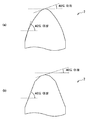
정면 방향 뿐만 아니라, 기울기 방향에서 보았을 때의 면내의 휘도 얼룩{斑; unevenness}도 저감하는 것이 가능한 조명 장치를 제공한다. 각 선모양 광원(10)으로부터 광학 시트(13)의 광 입사면에 수직으로 입사한 광이 볼록부(13A)의 표면에서 전{全}반사되어 반사판(11)으로 향하는 리턴광{戾光; return light}을 발생시키는 리턴광 발생 부분 r1이, 광학 시트(13)를 면(10A)의 법선 방향에서 보았을 때에 제1 영역 R1에서 차지하는 비율을 K1로 하고, 각 선모양 광원(10)으로부터 광학 시트(13)의 광 입사면에 수직으로 입사한 광이 볼록부(13B, 13C)의 표면에서 전반사되어 반사판(11)으로 향하는 리턴광을 발생시키는 리턴광 발생 부분 r2가, 광학 시트(13)를 면(10A)의 법선 방향에서 보았을 때에 제2 영역 R2에서 차지하는 비율을 K2로 했을 때, K1이 K2보다도 크게 되어 있다.Luminance unevenness in the plane when viewed in the tilt direction as well as in the front direction. Provided is an illumination device capable of reducing unevenness. Light incident from the respective linear light sources 10 perpendicularly to the light incident surface of the optical sheet 13 is totally reflected at the surface of the convex portion 13A and returns to the reflecting plate 11; The return light generation part r1 which generate | occur | produces return light} makes K1 the ratio which occupies in the 1st area | region R1 when the optical sheet 13 is seen from the normal line direction of the surface 10A, and it is optical from each linear light source 10. The optical sheet 13 includes a return light generating portion r2 for generating light returning perpendicularly to the light incident surface of the sheet 13 to the reflecting plate 11 by total reflection at the surfaces of the convex portions 13B and 13C. When K is taken as the ratio which occupies in 2nd area | region R2 when viewed from the normal line direction of surface 10A, K1 becomes larger than K2.
Description
본 발명은, 예를 들면 투과형의 액정 패널을 배후에서 조명하는 조명 장치 및 그것을 구비한 표시 장치에 관한 것이다.
The present invention relates to, for example, an illumination device for illuminating a transmissive liquid crystal panel from behind and a display device having the same.
종래부터, 워드 프로세서나 랩톱형 퍼스널컴퓨터 등의 표시 장치로서, 액정 패널의 배후에 백라이트(조명 장치)를 배치한 액정표시 장치가 이용되고 있다. 이와 같은 액정 표시 장치용 조명 장치로서는, 경량화 및 박형화의 요청으로, 도광판의 측단부에 형광관과 같은 선모양 광원을 배치하고, 이 도광판 위에 액정 패널을 설치한 에지 라이트형 조명 장치가 주류로 되어 있었다. 그러나, 텔레비전 용도 등의 최근의 표시 장치의 대형화에 수반해서, 상술한 에지 라이트형 조명 장치에서는 휘도가 불충분하게 되는 일이 많기 때문에, 근래에서는, 액정 패널의 바로 아래에 선모양 광원을 배치한 직하형{直下型} 조명 장치가 이용되고 있다(특허문헌 1).Background Art Conventionally, a liquid crystal display device in which a backlight (lighting device) is disposed behind a liquid crystal panel has been used as a display device such as a word processor or a laptop personal computer. As such a lighting device for liquid crystal display devices, an edge light type lighting device in which a line-like light source such as a fluorescent tube is disposed on the side end of the light guide plate, and a liquid crystal panel is provided on the light guide plate has become a mainstream at the request of weight reduction and thinning. there was. However, with the recent increase in the size of display devices such as television applications, the brightness of the above-described edge light type lighting devices often becomes insufficient. Therefore, in recent years, a linear light source is disposed directly under the liquid crystal panel. A type | mold lighting apparatus is used (patent document 1).
[선행기술문헌][Prior Art Literature]
[특허문헌][Patent Documents]
특허문헌 1: WO2006/071616
Patent Document 1: WO2006 / 071616
표시 장치의 대형화 및 박형화에 수반해서 조명 장치도 대형화 및 박형화되고, 조명 장치에 사용하는 선모양 광원의 개수가 증가함과 동시에, 선모양 광원의 바로 위에 배치되는 평판모양의 광학 소자와, 선모양 광원과의 간극{間隙; clearance}이 좁아지는 경향에 있다. 그러나, 선모양 광원의 개수가 증가하면, 조명 장치의 소비 전력이 증대하고, 텔레비전의 소비 전력도 증대해 버리므로, 선모양 광원의 수를 될 수 있는 한 늘리지 않고, 다시 말해 이웃{隣合; adjacent}하는 선모양 광원끼리의 간격을 넓히는 것에 의해 소비 전력의 증대량을 억제하는 것이 생각된다. 그런데, 그와 같이 하면, 조명 장치의 조사 광속의 면내 휘도가, 선모양 광원의 바로 위 위치에서 높아지고, 선모양 광원끼리 사이의 중앙 부분의 바로 위 위치에서 낮아져, 면내에 휘도 얼룩{斑; unevenness}이 발생해 버린다고 하는 문제가 있었다. 또, 선모양 광원의 바로 위에 배치되는 평판모양의 광학 소자와, 선모양 광원과의 간극을 좁게 한 경우에도 마찬가지로, 면내에 휘도 얼룩이 발생해 버린다고 하는 문제가 있었다.As the display device becomes larger and thinner, the lighting device becomes larger and thinner, the number of linear light sources used for the lighting device increases, and a flat plate-shaped optical element disposed directly above the linear light source, and a linear shape. Gap with a light source; clearance} tends to narrow. However, as the number of linear light sources increases, the power consumption of the lighting device increases and the power consumption of the television also increases, so that the number of linear light sources is not increased as much as possible, that is, the neighbors. It is conceivable to suppress the amount of increase in power consumption by increasing the distance between adjacent line light sources. By doing so, the in-plane luminance of the irradiated light beam of the illuminating device is increased at the position just above the linear light sources, and is lowered at the position just above the central portion between the linear light sources, resulting in luminance unevenness in the plane. There was a problem that unevenness occurred. In addition, even when the gap between the flat optical element and the linear light source disposed directly above the linear light source is narrowed, there is a problem that luminance unevenness is generated in the plane.
그래서, 내부에 확산재(필러)를 분산해서 형성된 확산판의 광 사출측의 면내에, 동일 형상의 비구면모양의 볼록부를 복수 설치하는 방책이 제안되어 있다. 이것에 의해, 필러에 의한 확산 효과 뿐만 아니라, 비구면 형상에 의한 선모양 광원의 바로 위의 광의 확산 효과를 얻을 수 있으므로, 휘도 얼룩을 개선할 수가 있다. 그러나, 그 효과는 한정적이며, 이웃하는 선모양 광원끼리의 간격을 넓히거나, 선모양 광원과 광학 소자와의 간격을 좁게 하는 것이 그다지 할 수 없다. 그래서, 또, 선모양 광원끼리의 사이의 중앙 부분의 바로 위 위치에서 볼록부를 프리즘 형상으로 하고, 선모양 광원끼리의 사이의 중앙 부분의 바로 위 위치의 정면 휘도를 증대시키는 것이 생각된다. 그러나, 그와 같이 하면, 정면에서 보았을 때의 면내의 휘도 얼룩을 개선할 수는 있지만, 기울기{비스듬한} 방향에서 보았을 때의 면내의 휘도 얼룩이 악화되어 버린다고 하는 문제가 있다.Therefore, a method has been proposed in which a plurality of aspherical convex portions having the same shape are provided in the surface on the light exit side of the diffusion plate formed by dispersing the diffusion material (filler) therein. As a result, not only the diffusion effect by the filler, but also the diffusion effect of the light directly above the linear light source due to the aspherical shape can be obtained, thereby improving luminance unevenness. However, the effect is limited, and it is not possible to widen the distance between adjacent line light sources or to narrow the space between the line light sources and the optical element. Therefore, it is also conceivable to make the convex portion at the position immediately above the central portion between the linear light sources, and to increase the front luminance at the position just above the central portion between the linear light sources. However, in this way, although the in-plane brightness unevenness seen from the front side can be improved, there exists a problem that the in-plane brightness unevenness seen from the inclination | tilt | interval (diagonal) deteriorates.
본 발명은 이러한 문제점을 감안해서 이루어진 것으로, 그 목적은, 정면 방향 뿐만 아니라, 기울기 방향에서 보았을 때의 면내의 휘도 얼룩도 저감하는 것이 가능한 조명 장치 및 표시 장치를 제공하는데 있다.The present invention has been made in view of the above problems, and an object thereof is to provide an illumination device and a display device capable of reducing not only the front direction but also the in-plane luminance unevenness seen from the inclination direction.
본 발명의 조명 장치는, 각각의 중심축이 서로 평행하게 됨과 동시에 하나의 면내에 포함되도록 배치된 복수의 선모양 광원과, 각 선모양 광원과 대향 배치된 반사판과, 하나의 면에 관해서 반사판의 반대측에 배치된 평판모양의 확산 부재와, 각 선모양 광원과 상기 확산 부재 사이에 배치된 광학 부재를 구비한 것이다. 여기서, 광학 부재는, 상기 하나의 면에 평행한 광 입사면과 광 사출면을 가지고 있다. 광 사출면에는, 각 선모양 광원과 상기하나의 면의 법선 방향으로 대향하는 제1 영역에 제1 입체 구조가 설치되어 있고, 하나의 선모양 광원과 상기 하나의 선모양 광원에 인접하는 다른 선모양 광원 사이의 중간 영역과 상기 하나의 면의 법선 방향으로 대향하는 제2 영역에 제2 입체 구조가 설치되어 있다. 그리고, 각 선모양 광원으로부터 광 입사면에 수직으로 입사한 광이 제1 입체 구조에 의해서 전{全}반사되어 반사판으로 향하는 리턴광{戾光; return light}을 발생시키는 제1 부분이, 광학 부재를 상기 하나의 면의 법선 방향에서 보았을 때에 제1 영역에서 차지하는 비율을 K1로 하고, 각 선모양 광원으로부터 광 입사면에 수직으로 입사한 광이 제2 입체 구조에 의해서 전반사되어 반사판으로 향하는 리턴광을 발생시키는 제2 부분이, 광학 부재를 상기 하나의 면의 법선 방향에서 보았을 때에 제2 영역에서 차지하는 비율을 K2로 했을 때, K1 및 K2가 이하의 식을 만족시키고 있다.The lighting apparatus of the present invention comprises a plurality of linear light sources arranged so that their respective central axes are parallel to each other and included in one plane, a reflecting plate arranged opposite to each linear light source, and one surface of the reflecting plate. It is provided with the flat plate-shaped diffusion member arrange | positioned at the opposite side, and the optical member arrange | positioned between each linear light source and the said diffusion member. Here, the optical member has a light incident surface and a light emitting surface parallel to the one surface. On the light exit surface, a first three-dimensional structure is provided in a first region facing each line-shaped light source and the one surface in the normal direction, and one line-shaped light source and another line adjacent to the one-line light source. A second three-dimensional structure is provided in the intermediate region between the shape light sources and the second region facing in the normal direction of the one surface. Then, the light incident perpendicularly to the light incident surface from each line-shaped light source is totally reflected by the first three-dimensional structure and returns to the reflecting plate. The first portion generating the return light} has a ratio K1 in the first region when the optical member is viewed in the normal direction of the one surface, and the light incident from the respective linear light sources perpendicularly to the light incident surface is When the second portion which totally reflects by the second three-dimensional structure and generates the return light directed to the reflecting plate has the ratio of K2 to the second region when the optical member is viewed from the normal direction of the one surface, K1 and K2 are The following formula is satisfied.
K1-K2〉0K1-K2〉 0
본 발명의 표시 장치는, 화상 신호에 의거해서 구동되는 패널과, 패널을 조명하는 상기 조명 장치를 구비한 것이다.The display apparatus of this invention is equipped with the panel driven based on an image signal, and the said lighting apparatus which illuminates a panel.
본 발명의 조명 장치 및 표시 장치에서는, 광학 부재에 있어서, K1이 K2보다도 크게 되어 있다. 다시 말해, 각 선모양 광원의 바로 위에 해당하는 제1 영역 쪽이 제1 영역 사이에 끼인 제2 영역보다도 광을 통하게 하기{통과시키기} 어렵게 되어 있으므로, 제1 영역으로부터의 리턴광은, 반사 시트 등에서 반사되는 등 해서, 조명 장치내를 순환한 후, 순환광의 대부분이 상대적으로 광을 통하게 하기 쉬운 제2 영역을 통과한다. 이것에 의해, 광학 부재에 입사한 광의 광량 분포와, 광학 부재를 통과한 광의 광량 분포를 대비하면, 제1 영역으로부터 제2 영역으로 광량의 이동이 생기게 된다. 또, 제2 영역 쪽이 제1 영역보다도 광을 통하기 쉽게 되어 있기 때문에, 제2 영역에서는 집광성이 약하고, 확산성이 강하다고 말할 수 있다. 이것에 의해, 제2 영역을 통과한 광의 광량은 정면 뿐만 아니라, 기울기 방향으로도 넓게 분포하고 있다.In the illumination device and the display device of the present invention, K1 is larger than K2 in the optical member. In other words, since the first region corresponding to each of the linear light sources is more difficult to pass (pass) the light than the second region sandwiched between the first regions, the return light from the first region is reflected sheet. After circulating in the lighting apparatus by reflecting from the back, or the like, most of the circulating light passes through the second region which is relatively easy to pass through the light. Thereby, when the light quantity distribution of the light which entered the optical member and the light quantity distribution of the light which passed through the optical member are contrasted, the light quantity shifts from a 1st area | region to a 2nd area | region. In addition, since the second region is easier to pass light than the first region, it can be said that the light condensation is weak in the second region, and the diffusivity is strong. Thereby, the light quantity of the light which passed the 2nd area | region is distributed not only in front but also in the diagonal direction widely.
본 발명의 조명 장치 및 표시 장치에 의하면, 광학 부재에 있어서, K1 이 K2보다도 크게 되도록 했으므로, 제1 영역으로부터 제2 영역으로 광량의 이동을 일으키게 하며, 또 제2 영역을 통과한 광의 광량을 정면 뿐만 아니라, 기울기 방향으로도 넓게 분포시킬 수가 있다. 이것에 의해, 정면 방향 뿐만 아니라, 기울기 방향에서 보았을 때의 면내의 휘도 얼룩도 저감할 수가 있다.
According to the illuminating device and the display device of the present invention, in the optical member, K1 is made larger than K2, so that the light amount is moved from the first area to the second area, and the light amount of the light passing through the second area is faced. In addition, it can also be widely distributed in the tilt direction. As a result, not only the front direction but also the in-plane luminance unevenness seen from the inclination direction can be reduced.
도 1은 본 발명의 1실시형태에 관계된 조명 장치의 1예의 단면 구성도,
도 2는 도 1의 광학 시트의 1예의 단면 구성도,
도 3은 도 1의 광학 시트의 볼록부의 각종 형상의 단면 구성도,
도 4는 리턴광 발생 부분에 대해서 설명하기 위한 개념도,
도 5는 얼룩률{斑率; unevenness ratio}과 P/H와의 관계를 도시한 관계도,
도 6은 도 1의 광학 시트의 광학 작용의 1예에 대해서 설명하기 위한 개념도,
도 7은 도 1의 광학 시트의 볼록부의 배치에 대해서 설명하기 위한 개념도,
도 8은 실시예에 관계된 광학 시트의 섹션마다의 볼록부의 단면 형상을 도시하는 도면,
도 9는 비교예에 관계된 광학 시트의 섹션마다의 볼록부의 단면 형상을 도시하는 도면,
도 10은 실시예의 정면 방향의 면내 휘도 분포를 도시하는 분포도,
도 11은 실시예의 기울기 방향의 면내 휘도 분포를 도시하는 분포도,
도 12는 비교예의 정면 방향의 면내 휘도 분포를 도시하는 분포도,
도 13은 비교예의 기울기 방향의 면내 휘도 분포를 도시하는 분포,
도 14는 원반을 절삭하는 칼날{刃物; blade}의 선단 형상의 1예를 도시하는 단면 구성도,
도 15는 원반의 절삭 방법의 1예에 대해서 설명하기 위한 개념도,
도 16은 도 15의 절삭 방법에 의해 형성된 원반을 이용해서 작성한 광학 시트의 단면 구성도,
도 17은 원반의 절삭 방법의 다른 예에 대해서 설명하기 위한 개념도,
도 18은 도 17의 절삭 방법에 의해 형성된 원반을 이용해서 작성한 광학 시트의 단면 구성도,
도 19는 도 1의 조명 장치의 1변형예의 단면 구성도,
도 20은 도 1의 조명 장치의 다른 변형예의 단면 구성도,
도 21은 도 1의 조명 장치의 그 밖의 변형예의 단면 구성도,
도 22는 도 1의 조명 장치의 그 밖의 변형예의 단면 구성도,
도 23은 도 1의 조명 장치의 그 밖의 변형예의 단면 구성도,
도 24는 도 1의 조명 장치의 그 밖의 변형예의 단면 구성도,
도 25는 도 1의 조명 장치의 1적용예에 관계된 표시 장치의 단면 구성도.1 is a cross-sectional configuration diagram of an example of a lighting apparatus according to an embodiment of the present invention;
2 is a cross-sectional configuration diagram of an example of the optical sheet of FIG. 1;
3 is a cross-sectional configuration diagram of various shapes of convex portions of the optical sheet of FIG. 1;
4 is a conceptual diagram for explaining a return light generation portion;
5 shows staining rate; relationship showing unevenness ratio} and P / H,
6 is a conceptual diagram for explaining an example of the optical action of the optical sheet of FIG. 1;
7 is a conceptual diagram for explaining the arrangement of the convex portions of the optical sheet of FIG. 1;
8 is a diagram showing a cross-sectional shape of the convex portion for each section of the optical sheet according to the embodiment;
9 is a diagram showing a cross-sectional shape of the convex portions for each section of the optical sheet according to the comparative example;
10 is a distribution chart showing an in-plane luminance distribution in the front direction of the embodiment;
11 is a distribution chart showing an in-plane luminance distribution in the tilt direction of the embodiment;
12 is a distribution chart showing an in-plane luminance distribution in the front direction of the comparative example;
13 is a distribution showing the in-plane luminance distribution in the inclination direction of the comparative example,
14 is a blade for cutting the disc; Sectional block diagram which shows an example of the tip shape of a blade},
15 is a conceptual diagram for explaining an example of a cutting method of a disc;
FIG. 16 is a cross-sectional configuration diagram of an optical sheet prepared using a disk formed by the cutting method of FIG. 15;
17 is a conceptual diagram for explaining another example of the cutting method of the disc;
FIG. 18 is a cross-sectional configuration diagram of an optical sheet created using a disk formed by the cutting method of FIG. 17;
19 is a cross-sectional configuration diagram of a modification of the lighting apparatus of FIG. 1;
20 is a cross-sectional configuration diagram of another modification of the lighting apparatus of FIG. 1;
FIG. 21 is a sectional configuration diagram of still another modification of the lighting apparatus of FIG. 1; FIG.
22 is a cross-sectional configuration diagram of still another modification of the lighting apparatus of FIG. 1;
FIG. 23 is a sectional configuration diagram of still another modification of the lighting apparatus of FIG. 1; FIG.
24 is a cross-sectional configuration diagram of still another modification of the lighting apparatus of FIG. 1;
25 is a cross-sectional configuration diagram of a display device according to an application example of the lighting device of FIG. 1.
이하, 본 발명의 실시형태에 대해서, 도면을 참조하여 상세하게 설명한다.EMBODIMENT OF THE INVENTION Hereinafter, embodiment of this invention is described in detail with reference to drawings.
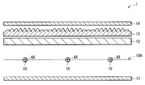
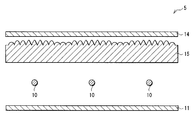
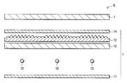
도 1은, 본 발명의 1실시형태에 관계된 조명 장치(1)의 단면 구성을 도시한 것이다.1 shows a cross-sectional configuration of a
이 조명 장치(1)는, 복수의 선모양 광원(10)과, 반사판(11)과, 확산판(12)과, 광학 시트(13)(광학 부재)와, 확산 시트(14)(확산 부재)를 구비한 것이다. 반사판(11)은, 각 선모양 광원(10)의 배후에, 각 선모양 광원(10)과 대향 배치되어 있으며, 확산판(12), 광학 시트(13) 및 확산 시트(14)는, 각 선모양 광원(10)에 관해서 반사판(11)의 반대측에, 각 선모양 광원(10) 측으로부터 이 순{順}으로 배치됨과 동시에 각 선모양 광원(10)과 대향 배치되어 있다.This illuminating
복수의 선모양 광원(10)은, 예를 들면 열음극관(HCFL; Hot Cathode Fluorescent Lamp), 냉음극관(CCFL; Cold Cathode Fluorescent Lamp), 또는 복수의 점모양 광원(LED 등)이 선모양으로 배치된 것 등으로 이루어지며, 예를 들면 도 1에 도시한 바와 같이, 각각의 중심축 AX가 서로 평행 또는 대략 평행하게 됨과 동시에 하나의 면(10A)내에 포함되도록 배치되어 있다. 또한, 도시하지 않지만, 복수의 선모양 광원(10)이 격자모양으로 배치되어 있어도 좋다.The plurality of linear
반사판(11)은, 각 선모양 광원(10)의 중심축 AX를 포함하는 면(10A)으로부터 소정의 간극만큼 떨어진 위치에 대향 배치되어 있으며, 선모양 광원(10)측에 반사면을 가지고 있다. 이 반사면은, 정{正}반사 뿐만 아니라, 확산 반사의 기능도 가지고 있는 것이 바람직하다. 이와 같은 정반사 및 확산 반사의 기능을 발현{發現}하기 위해서, 수지를 백색으로 착색한 것을 반사면에 이용하는 것이 가능하지만, 그 경우에는 높은 광선 반사 특성이 얻어지는 것이 바람직하다. 그와 같은 재료로서는, 예를 들면 폴리카보네이트 수지, 폴리부틸렌 테레프탈레이트 수지 등을 들 수 있다.The reflecting
확산판(12)은, 예를 들면 비교적 두꺼운{厚手; thick} 판모양의 투명 수지의 내부에 확산재(필러)를 분산해서 형성된 광 확산층을 가지는 두껍고 강성{剛性}이 높은 광학 시트이다. 이 확산판(12)은, 다른 광학 시트(예를 들면, 광학 시트(13) 및 확산 시트(14))를 지지하는 지지체로서도 기능한다. 또한, 확산판(12)은, 비교적 두꺼운 판모양의 투명 수지의 내부에 확산재(필러)를 분산해서 형성된 것과, 비교적 얇은{薄手; thin} 필름모양의 투명 수지 위에 확산재를 포함하는 투명 수지(바인더)를 도포해서 형성된 것을 조합한 것이더라도 좋다.The
여기서, 판모양 또는 필름모양의 투명 수지에는, 예를 들면 PET, 아크릴 및 폴리카보네이트 등의 광 투과성 열가소성 수지가 이용된다. 상기 확산판(12)에 포함되는 광 확산층은, 예를 들면 1㎜ 이상 5㎜ 이하의 두께를 가지고 있다. 또, 광 확산재는, 예를 들면 0.5㎛ 이상 10㎛ 이하의 평균 입자 지름을 가지는 입자로 이루어지고, 상기 광 확산층 전체의 중량에 대해서 0.1중량부 이상 10중량부 이하의 범위에서 투명 수지중에 분산되어 있다. 광 확산재의 종류로서는, 예를 들면 유기 필러나 무기 필러 등을 들 수 있지만, 광 확산재로서 공동성{空洞性} 입자를 써도 좋다. 이것에 의해, 이 확산판(12)은, 각 선모양 광원(10)으로부터의 광이나 광학 시트(13)측으로부터의 리턴광을 확산하는 기능을 가지고 있다.Here, light-transmitting thermoplastic resins, such as PET, an acryl, and polycarbonate, are used for plate-shaped or film-shaped transparent resin, for example. The light diffusion layer included in the
광 확산층이 1㎜보다 얇아지면, 광 확산성이 손상되고, 또 확산판(12)을 패키지{筐體; package}(도시하지 않음)로 지지할 때에 시트 강성을 확보할 수 없게 될 우려가 있다. 또, 광 확산층이 5㎜보다 두꺼워지면, 확산판(12)이 광원으로부터의 광에 의해서 가열되었을 때에, 그 열을 방산하는 것이 곤란해지며, 확산판(12)이 휘어질 우려가 있다. 광 확산재의 평균 입자 지름이 0.5 ㎛ 이상 10㎛ 이하의 범위에 있고, 광 확산재가 광 확산층 전체의 중량에 대해서 0.1중량부 이상 10중량부 이하의 범위에서 투명 수지중에 분산되어 있는 경우에는, 광 확산재로서의 효과가 효율좋게 발현하며, 후술하는 광학 시트(13)와의 조합으로 효율좋게 휘도 얼룩을 해소할 수가 있다.If the light diffusing layer becomes thinner than 1 mm, the light diffusing property is impaired, and the diffusing
확산 시트(14)는, 예를 들면 비교적 얇은 필름모양의 투명 수지 위에 광 확산재를 포함하는 투명 수지를 도포해서 형성된 얇은{薄} 광학 시트이다. 이 확산 시트(14)는, 확산판(12) 및 광학 시트(13)를 통과한 광을 확산하는 기능을 가지고 있다.The
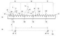
광학 시트(13)는, 예를 들면 도 1, 도 2의 (a)에 도시한 바와 같이, 복수의 볼록부(13A, 13B, 13C)가 확산 시트(14)측(광 사출측)의 면에 배치된 얇은 광학 시트이다. 도 2의 (a)는, 도 1의 광학 시트(13)를 확대해서 도시한 것이며, 도 2의 (b)는, 도 2의 (a)의 광학 시트(13)의 볼록부(13A, 13B, 13C)의 위치와 선모양 광원(10)과의 위치 관계를 도시한 것이다 . 또한, 볼록부(13A)가 본 발명의 「제1 볼록부」의 1구체예에 상당하며, 볼록부(13B, 13C)가 본 발명의 「제2 볼록부」의 1구체예에 상당한다. 또한, 도 1에는, 광학 시트(13)가 확산판(12)과 별체{別體}로 배치되어 있는 경우가 예시되어 있지만, 확산판(12)의 표면 위에 접착제 등으로 서로 붙여져{貼合; bond} 있어도 좋다.As for the
이 광학 시트(13)는, 예를 들면 투광성을 가지는 수지 재료, 예를 들면 1 또는 복수 종류의 열가소성 수지를 이용해서 일체적으로 형성되어 있어도 좋고, 또 투광성의 기재{基材; base material}, 예를 들면 PET(폴리에틸렌 테레프탈레이트) 위에 에너지선(예를 들면, 자외선) 경화 수지를 전사해서, 형성되어 있어도 좋다.The
열가소성 수지로서는, 광의 사출 방향을 제어한다고 하는 기능을 고려하면, 굴절률 1.4 이상의 것을 이용하는 것이 바람직하다. 이와 같은 수지로서는, 예를 들면 폴리카보네이트 수지, PMMA(폴리메틸 메타크릴레이트 수지) 등의 아크릴 수지, 폴리에틸렌(PE) 및 폴리프로필렌(PP) 등의 폴리올레핀계 수지, 폴리에틸렌 테레프탈레이트 등의 폴리에스테르 수지, MS(메틸메타크릴레이트와 스틸렌의 공중합체) 등의 비정성{非晶性} 공중합 폴리에스테르 수지, 폴리스틸렌 수지, 폴리염화 비닐 수지 , 시클로올레핀계 수지, 우레탄계 수지, 천연 고무계 수지 및 인공 고무계 수지, 및 이들의 복수의 조합 등을 들 수 있다.As the thermoplastic resin, in consideration of the function of controlling the injection direction of light, one having a refractive index of 1.4 or more is preferably used. As such resin, For example, polycarbonate resin, acrylic resin, such as PMMA (polymethyl methacrylate resin), polyolefin resin, such as polyethylene (PE) and polypropylene (PP), polyester resin, such as polyethylene terephthalate , Amorphous copolymerized polyester resins such as MS (copolymer of methyl methacrylate and styrene), polystyrene resin, polyvinyl chloride resin, cycloolefin resin, urethane resin, natural rubber resin and artificial rubber resin And combinations thereof.
복수의 볼록부(13A, 13B, 13C)는, 선모양 광원(10)의 면(10A)과 평행한 평면을 따라 연재{延在; extend}하는 선모양, 뿔체모양{錐體狀; spindle}, 또는 와플모양의 입체 형상을 가지고 있다. 각 볼록부(13A, 13B, 13C)가 선모양의 입체 형상을 가지고 있는 경우에는, 해당 각 볼록부(13A, 13B, 13C)의 연재 방향이 선모양 광원(10)의 연재 방향과 서로 평행하게 되도록 병렬 배치되어 있는 것이 바람직하지만, 선모양 광원(10)의 연재 방향에 대해서 광학 특성상 허용할 수 있는 범위내에서 교차하도록 배치되어 있어도 좋다. 도시하지 않지만, 복수의 점모양 광원이 격자모양으로 배치되어 있는 경우에는, 2장의 광학 시트(13)를 겹쳐서 배치하거나, 복수의 볼록부(13A, 13B, 13C)를 뿔체모양, 또는 와플모양의 입체 형상으로 하거나 하는 것이 바람직하다.The plurality of
복수의 볼록부(13A)는, 각 선모양 광원(10)과 면(10A)의 법선 방향으로 대향하는 제1 영역 R1 내에 배치되어 있다. 각 볼록부(13A)는, 제1 영역 R1 전체로서 선모양 광원(10)측으로부터의 입사광을 상대적으로 통하게 하기 어려운 광학 특성을 발현하는 입체 구조(제1 입체 구조)로 되어 있다. 또, 복수의 볼록부(13B, 13C)는, 하나의 선모양 광원(10)과 하나의 선모양 광원(10)에 인접하는 다른 선모양 광원(10) 사이의 중간 영역과 면(10A)의 법선 방향으로 대향하는 제2 영역 R2 내에 배치되어 있다. 각 볼록부(13B, 13C)는, 제2 영역 R2 전체로서 선모양 광원(10)측으로부터의 입사광을 상대적으로 통하게 하기 쉬운 광학 특성을 발현하는 입체 구조(제2 입체 구조)로 되어 있다. 또, 제2 영역 R2 내에서, 볼록부(13B)는 상대적으로 선모양 광원(10) 근처에 배치되어 있고, 볼록부(13C)는 상대적으로 선모양 광원(10)으로부터 떨어져서, 다시 말해 서로 이웃하는 선모양 광원(10)끼리의 정확히 한가운데 및 그 근방에 배치되어 있다.The plurality of
제1 입체 구조가 제2 입체 구조보다도 선모양 광원(10)측으로부터의 입사광을 상대적으로 통하게 하기 어렵다고 하는 것은, A1, A2(후술)가 이하의 식(1)을 만족시키고 있는 것과 거의 등가이다.It is almost equivalent that A1 and A2 (described later) satisfy the following formula (1) that the first three-dimensional structure is less likely to pass incident light from the linear
A1-A2〉0…(1)A1-A2> 0... (One)
39≤ψ1≤69 …(2)39? (2)
39≤ψ2≤69 …(3)39? (3)
ψ1은, 도 2에 도시한 바와 같이, 볼록부(13A)에 접하는 접면 T1과, 면(10A)과 평행한 면 T2가 이루는 각이다. ψ2는, 도 2에 도시한 바와 같이, 볼록부(13B) 또는 볼록부(13C)에 접하는 접면 T3과, 면(10A)과 평행한 면 T2가 이루는 각이다. A1은, ψ1이 식(2)을 만족시키는 부분이, 광학 시트(13)를 면(10A)의 법선 방향에서 보았을 때에 제1 영역 R1에서 차지하는 비율이다. A2는, ψ2가 식(3)을 만족시키는 부분이, 광학 시트(13)를 면(10A)의 법선 방향에서 보았을 때에 제2 영역 R2에서 차지하는 비율이다.2 is an angle formed by the contact surface T1 in contact with the
ψ1, ψ2가 39° 미만인 경우에는, 광학 시트(13)의 이면에 수직으로 입사한 광에 있어서, 볼록부(13A, 13B, 13C)의 표면을 투과하는 비율이 광학 시트(13)에서 반사되어 리턴광으로 되는 비율보다도 지배적으로 되어 있다. 또, ψ1, ψ2가 69°를 넘는 경우에는, 광학 시트(13)의 이면에 수직으로 입사한 광이 볼록부(13A, 13B, 13C)의 하나의 표면에서 전반사되지만, 그 반사광이 볼록부(13A, 13B, 13C)의 다른 표면을 투과하고, 그 투과광이 재차, 볼록부(13A, 13B, 13C)에 입사하는 일이 없다. 그 때문에, 이 경우에도, 광학 시트(13)의 이면에 수직으로 입사한 광에 있어서, 광학 시트(13)를 투과하는 비율이 광학 시트(13)에서 반사되어 리턴광으로 되는 비율보다도 지배적으로 되어 있다. 따라서, 제1 영역 R1(볼록부(13A)이, 제2 영역 R2(볼록부 13B, 13C)보다도, 정면 휘도가 높고, 기울기 방향의 휘도가 낮으므로, 제1 영역 R1에서는 제2 영역 R2보다도 집광성이 강하고, 제2 영역 R2에서는 제1 영역 R1보다도 집광성이 약하다고 말할 수 있다.When ψ1 and ψ2 are less than 39 °, in the light incident perpendicularly to the rear surface of the
ψ1 및 ψ2는, 볼록부(13A, 13B, 13C)의 꼭대기부{頂部}로부터 바닥부{底部}로 향함에 따라서 연속적 또는 단속적{斷續的; intermittently}으로 크게 되어 있는 것이 바람직하다. 예를 들면, 볼록부(13A)가, 도 2에 도시한 바와 같이, 꼭대기부(13D) 및 그 근방에 볼록모양의 비구면모양 곡면 S1을 가짐과 동시에, 그 이외의 부분에 곡면 S1과 매끄럽게 연속하는 경사 평면 S2를 가지는 삼각 기둥모양의 입체 구조를 가지고 있는 경우에는, 경사 평면 S2의 접면의 각도(경사 평면 S2의 경사각)가 상기의 식(2)를 만족시킴과 동시에, 곡면 S1의 접면의 각도가 적어도 꼭대기부(13D) 및 꼭대기부(13D)의 극히 근방에서 상기의 식(2)을 만족시키지 않을 정도로 작게 되어 있다.ψ1 and ψ2 are continuous or intermittent as they go from the top of the
또, 예를 들면 도 2에 도시한 바와 같이, 볼록부(13B)가 전체로서 볼록모양의 비구면모양 곡면 S3을 가짐과 동시에, 볼록부(13C)가 전체로서 볼록모양의 비구면모양의 곡면 S4를 가지고 있는 경우에는, 곡면S3, S4의 접면의 각도가 모두 상기의 식(3)을 만족시킴과 동시에 볼록부(13A)의 경사 평면 S2의 접면의 각도보다도 완만하게 (작게) 되어 있으며, 또한 곡면 S4의 접면의 각도 쪽이 곡면 S3의 접면의 각도보다도 완만하게 (작게) 되어 있다.For example, as shown in Fig. 2, the
또한, 볼록부(13A, 13B, 13C)는, 위에서 예시한 형상에 한정되는 것은 아니며, 상기의 식(1)-(3)을 만족시키는 범위내에서 변형가능한 것이다.In addition, the
예를 들면, 볼록부(13A)는, 도 2의 볼록부(13B, 13C)에 도시한 바와 같은 비구면모양의 볼록 형상으로 되어 있어도 좋고, 꼭대기부에 둥그스름함이 없는 삼각 기둥 형상(프리즘 형상)이나, 도 3의 (a)에 도시한 바와 같은 다수의 경사 평면으로 구성된 다각 기둥 형상, 도 3의 (b)에 도시한 바와 같은 구면 형상, 도 3의 (c)에 도시한 바와 같은 평탄면(13G)을 포함하는 형상으로 되어 있어도 좋다. 또, 도 3의 (c)에 도시한 바와 같이, 서로 이웃하는 볼록부(13A) 사이에 평탄면(13H)이 설치되어 있어도 좋다. 또, 예를 들면 볼록부(13B, 13C)는, 꼭대기부(13E, 13F) 및 그 근방에 볼록모양의 비구면모양의 곡면을 가짐과 동시에, 그 이외의 부분에 그 곡면과 매끄럽게 연속하는 경사 평면을 가지는 삼각 기둥모양이나, 도 3의 (a)에 도시한 바와 같은 다수의 경사 평면으로 구성된 다각 기둥 형상, 도 3의 (b)에 도시한 바와 같은 구면 형상, 도 3의 (c)에 도시한 바와 같은 평탄면(13G)을 포함하는 형상으로 되어 있어도 좋다. 또한, 볼록부(13A)와, 볼록부(13B 또는 13C)가 각각 볼록모양의 곡면을 가지고 있는 경우에는, 볼록부(13A)의 곡면의 곡률이 볼록부(13B 또는 13C)의 곡면의 곡률보다도 작게 되어 있는 것이 바람직하고, 마찬가지로 볼록부(13A)와, 볼록부(13B 또는 13C)가 각각 경사 평면을 가지고 있는 경우에는, 볼록부(13A)의 경사 평면의 경사각이 볼록부(13B 또는 13C)의 경사 평면의 경사각보다도 크게 되어 있는 것이 바람직하다. 또, 볼록부(13A)에 경사각이 큰 경사 평면을 설치한 결과, 볼록부(13A)의 높이가 볼록부(13B 또는 13C)의 높이보다도 높게 되어 있어도 좋다. 또, 도 3의 (c)에 도시한 바와 같이, 서로 이웃하는 볼록부(13B) 사이나, 서로 이웃하는 볼록부(13C) 사이, 서로 이웃하는 볼록부(13B)와 볼록부(13C) 사이에 평탄면(13H)이 설치되어 있어도 좋다. 또, 평탄면(13H)을 볼록부(13A, 13B, 13C)의 비형성 영역에 설치할 뿐만 아니라, 또 평탄면을 볼록부(13A, 13B, 13C)의 꼭대기부 등에 설치해도 좋다. 또한, 제1 영역 R1과 제2 영역 R2가 각각 평탄면을 가지고 있는 경우에는, 제1 영역 R1에서의 평탄면이, 광학 시트(13)를 면(10A)의 법선 방향에서 보았을 때에 제1 영역 R1에서 차지하는 비율을 K3으로 하고, 제2 영역 R2에서의 평탄면이, 광학 시트(13)를 면(10A)의 법선 방향에서 보았을 때에 제2 영역 R2에서 차지하는 비율을 K4로 했을 때, K3 및 K4가 이하의 식(4)을 만족시키는 것이 바람직하다.For example, the
K4-K3〉0 …(4)K4-K3> 0. (4)
단, 식(2), 식(3)은, 광학 부재에 일반적으로 쓰이는, 굴절률 1.5∼1.6 정도의 재료를 광학 시트(13)에 이용한 경우에 매우 적합하게 들어맞는 것이다. 그 때문에, 일반적이지 않은 재료를 광학 시트(13)에 이용한 경우에는, 상기의 식(2), 식(3)의 상한 및 하한의 값이 약간 어긋나므로, 재료에 따라 상한 및 하한의 값을 미{微; slightly}조정하는 것이 필요하게 된다.However, Formula (2) and Formula (3) are suitable for the case where the material of about 1.5-1.6 refractive index generally used for an optical member is used for the
또, 상기 식(1)∼식(3)은, 광학 시트(13)의 광 입사면에 입사하는 광이 일반적으로 가지고 있는 갖가지 프로파일에 대해서 적용가능한 것이다. 따라서, 광학 시트(13)의 광 입사면에 입사하는 광이, 광 입사면에 수직으로 입사하는 성분의 휘도가 광 입사면에 비스듬하게 입사하는 성분의 휘도보다도 높은 프로파일을 갖고 있는 경우나, 광 입사면에 수직으로 입사하는 성분의 휘도가 광 입사면에 비스듬하게 입사하는 성분의 휘도와 거의 똑같은 프로파일을 갖고 있는 경우(전형적으로는, 램버트{Lambert}광으로 되어 있는 경우) 등에 있어서도, 상기 식(1)∼식(3)은 성립한다.Moreover, said Formula (1)-Formula (3) is applicable to the various profiles which the light which injects into the light-incidence surface of the
또, 제2 영역 R2 내를 선모양 광원(10)으로부터의 거리에 따라 복수의 섹션으로 분할한 경우에, ψ2가 식(3)을 만족시키는 부분이, 광학 시트(13)를 면(10A)의 법선 방향에서 보았을 때에, 분할한 복수의 섹션에서 차지하는 각각의 비율이, 선모양 광원(10)으로부터 멀어짐에 따라서 서서히 또는 단속적으로 커지는 것이 바람직하다. 또, 제1 영역 R1 내를 선모양 광원(10)으로부터의 거리에 따라 복수의 섹션으로 분할한 경우에, ψ1이 식(2)를 만족시키는 부분이, 광학 시트(13)를 면(10A)의 법선 방향에서 보았을 때에, 분할한 복수의 섹션에서 차지하는 각각의 비율이, 선모양 광원(10)으로부터 멀어짐에 따라서 서서히 또는 단속적으로 커지는 것이 바람직하다.In the case where the inside of the second region R2 is divided into a plurality of sections according to the distance from the linear
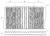
볼록부(13A, 13B, 13C)는, 도 4의 (a), (b)에 도시한 바와 같이, 각 선모양 광원(10)으로부터 광학 시트(13)의 광 입사면에 수직으로 입사한 광이 볼록부(13A)의 표면에서 전반사되고 반사판(11)으로 향하는 리턴광을 발생시키는 리턴광 발생 부분 R1(제1 부분)이, 광학 시트(13)를 면(10A)의 법선 방향에서 보았을 때에 제1 영역 R1에서 차지하는 비율을 K1로 하고, 각 선모양 광원(10)으로부터 광학 시트(13)의 광 입사면에 수직으로 입사한 광이 볼록부(13B, 13C)의 표면에서 전반사되고 반사판(11)으로 향하는 리턴광을 발생시키는 리턴광 발생 부분 r2(제2 부분)가, 광학 시트(13)를 면(10A)의 법선 방향에서 보았을 때에 제2 영역 R2에서 차지하는 비율을 K2로 했을 때, K1 및 K2는 적어도 이하의 식(5)를 만족시키고 있으며, 이하의 식(6)∼식(10)을 만족시키고 있는 것이 바람직하다. 또, K1 및 K2가 식(5)∼식(10)을 만족시키는 경우에, K2=0으로 되어 있는 것이 바람직하다.The
K1-K2〉0…(5)K1-K2> 0.. (5)
K1-K2≥0.03…(6)K1-K2 ≧ 0.03... (6)
K1-K2≥0.06…(7)K1-K2 ≧ 0.06... (7)
K1-K2≥0.12…(8)K1-K2 ≧ 0.12... (8)
K1-K2≥0.15…(9)K1-K2 ≧ 0.15... (9)
K1-K2≥0.18…(10)K1-K2 ≧ 0.18... 10
도 4의 (a)는, 광학 시트(13)를 위면{上面}에서 보았을 때의 리턴광 발생 부분 r1, r2의 분포의 1예를 모식적으로 도시한 것이며, 도 4의 (b)는, 광학 시트(13)의 측면도이며, 도 4의 (a)에 도시한 리턴광 발생 부분 r1, r2의 분포와, 볼록부(13A, 13B, 13C)와의 관계를 도시한 것이다.FIG. 4A schematically illustrates one example of distribution of return light generating portions r1 and r2 when the
도 5는, 이하의 식(11)에 의해서 구해지는 얼룩률과 P/H와의 관계를 도시한 것이다. 여기서, P는, 하나의 선모양 광원(10)의 중심축 AX와 하나의 선모양 광원(10)에 인접하는 다른 선모양 광원(10)의 중심축 AX와의 거리이다(도 2 참조). H는, 광학 시트(13)중 선모양 광원(10)측(면(10A)측)의 면과 면(10A)과의 거리이다(도 2 참조). 또한, 도 5의 얼룩률은 확산 시트(14)로부터의 사출광을 실측{實測}하는 것에 의해 구해진 것이다. 도 5중의 파선{破線}은 얼룩률 3%인 곳에 그어져 있다. 얼룩률 3%라고 하는 것은, 사람이 표시 얼룩을 시인{視認; recognize}할 수 없는(또는 표시 얼룩이 신경쓰이지 않는) 상한이며, 표시 품질에서의 지침의 하나로 되어 있다.FIG. 5 shows the relationship between the unevenness ratio and P / H obtained by the following equation (11). Here, P is the distance between the central axis AX of one linear
얼룩률(%)=((최대 휘도-최소 휘도)/평균 휘도)×100…(11)Unevenness (%) = ((maximum luminance-minimum luminance) / average luminance) x 100... (11)
도 5로부터, K1 및 K2가 식(6)을 만족시키는 경우에는, P/H를 최대로 3.4까지 크게 할 수가 있다. 그리고, K1 및 K2가 식(7)을 만족시키는 경우에는 P/H를 최대로 4.0까지, K1 및 K2가 식(8)을 만족시키는 경우에는 P/H를 최대로 4.7까지, K1 및 K2가 식(9)를 만족시키는 경우에는 P/H를 최대로 5.3까지, K1 및 K2가 식(10)을 만족시키는 경우에는 P/H를 최대로 5.9까지 크게 할 수가 있다.5, when K1 and K2 satisfy Formula (6), P / H can be enlarged to 3.4 at maximum. If K1 and K2 satisfy Eq. (7), P / H is at most 4.0. If K1 and K2 satisfy Eq. (8), P / H is at most 4.7, and K1 and K2 are When the expression (9) is satisfied, P / H can be maximized up to 5.3, and when K1 and K2 satisfy the expression (10), P / H can be increased up to 5.9 at maximum.
다음에, 본 실시형태의 조명 장치(1)의 작용 및 효과에 대해서 설명한다.Next, the operation and effect of the
본 실시형태의 조명 장치(1)에서는, 각 선모양 광원(10)으로부터 사출된 광은, 확산판(12)에 직접, 또는 반사판(11) 등에서 반사된 후 입사하고, 확산판(12)에서 확산된다. 그 확산광은, 광학 시트(13)의 이면에 입사하며, 위면에 형성된 볼록부(13A, 13B, 13C)의 형상에 따라 집광되거나, 확산되거나 한 후, 확산 시트(14)에서 확산되고, 확산 시트(14) 위에 배치된 피{被}조사물(도시하지 않음)을 조명한다.In the illuminating
일반적으로, 프리즘 시트는, 여러가지 방향으로부터의 입사광에 대해서, 특정 방향의 광을 정면 방향(입사면과 수직인 방향)으로 입상{立上; orient}시키며, 입사면에 수직에 가까운 각도로 입사한 광을 전반사하고 광원측으로 되돌려보내도록 작용한다. 이와 같이 작용하는 프리즘 시트의 개개의 프리즘의 밑각{底角}은 통상, 40도 이상 58도 이하로 되어 있기 때문에, 이와 같은 범위내의 경사각을 구비한 광학 시트는, 상기한 프리즘 시트와 마찬가지로, 강한 집광작용을 가질 뿐만 아니라, 많은 광을 되돌려보내는 작용, 다시 말해 광을 통하게 하기 어렵게 하는 작용도 가지고 있다. 따라서, 강한 집광 작용을 가지는 입체 구조는, 리턴광을 발생시키는 입체 구조이기도 하다.In general, a prism sheet is formed in which light in a specific direction is granulated in the front direction (direction perpendicular to the incident surface) with respect to incident light from various directions; orients and acts to totally reflect the light incident at an angle close to the incidence plane and return it to the light source side. Since the base angle of each prism of the prism sheet which acts in this way is set to 40 degree | times or more and 58 degrees or less normally, the optical sheet provided with the inclination angle in such a range is strong similarly to the prism sheet mentioned above. Not only does it have a condensing action, it also has the action of returning a lot of light, that is, making it difficult to let light through. Therefore, the three-dimensional structure which has a strong light condensing action is also the three-dimensional structure which generate | occur | produces return light.
상기의 것에 입각하면, 집광 작용이 약한(혹은 확산성이 강한) 입체 구조는, 광을 통하게 하기 쉽고, 리턴광을 발생시키기 어려운 입체 구조이기도 하다고 말할 수 있다. 그 때문에, 상대적으로 집광 작용이 강한 입체 구조와, 상대적으로 집광 작용이 약한(혹은 확산성이 강한) 입체 구조가 혼재하는 광학 시트를 광원의 바로 위에 설치함과 동시에, 광원의 바로 아래에 반사판을 설치한 경우에는, 상대적으로 집광 작용이 강한 입체 구조에서 반사되어 반사판으로 향하는 리턴광은, 반사판 등에서 반사되는 등 해서, 조명 장치내를 순환한 후, 순환광의 대부분이 상대적으로 광을 통하게 하기 쉬운 부분, 다시 말해 상대적으로 집광 작용이 약한(혹은 확산성이 강한) 입체 구조를 통과한다.Based on the above, it can be said that the three-dimensional structure with weak light condensing action (or strong diffusivity) is also a three-dimensional structure that is easy to pass light and hardly generates return light. Therefore, an optical sheet in which a three-dimensional structure having a relatively strong light collection action and a three-dimensional structure having a relatively low light collection action is mixed is provided directly above the light source, and at the same time, a reflector is placed directly under the light source. When installed, the return light that is reflected in a three-dimensional structure with a strong light condensing effect and is directed to the reflecting plate is reflected by a reflecting plate or the like, and then circulates in the lighting apparatus, and thus, a large portion of the circulating light is relatively easy to pass through the light. In other words, it passes through a relatively weak (or highly diffuse) three-dimensional structure.
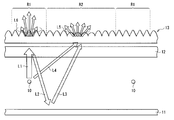
이것을 본 실시형태에 적용시키면, 각 선모양 광원(10)의 바로 위에 해당하는 제1 영역 R1 쪽이 제1 영역 R1 사이에 끼인 제2 영역 R2보다도 광을 통하게 하기 어렵게 되어 있으므로(다시 말해, 식(1)∼식(3)과, 식(5)을 만족시키고 있으므로), 도 6에 도시한 바와 같이, 제1 영역 R1에의 입사광 L1중 제1 영역 R1에서 반사되어 제1 영역 R1로부터 반사판(11)으로 향하는 리턴광 L2가, 반사판(11) 등에서 반사되는 등 해서, 조명 장치(1)내를 순환한 후, 순환광 L3의 대부분이 상대적으로 광을 통하게 하기 쉬운 제2 영역 R2를 통과한다. 또, 선모양 광원(10)으로부터 직접 제2 영역 R2에 입사하는 입사광 L4의 대부분도 제2 영역 R2를 통과한다. 그 결과, 광학 시트(13)에 입사한 광의 광량 분포와 , 광학 시트(13)를 통과한 광의 광량 분포를 대비하면, 제1 영역 R1로부터 제2 영역 R2로 광량의 이동이 생기게 된다.When this is applied to this embodiment, since the 1st area | region R1 corresponding to just above each linear
또, 제2 영역 R2 쪽이 제1 영역 R1보다도 광을 통하게 하기 쉽게 되어 있으므로, 제2 영역 R2에서는 집광성이 약하거나(또는 집광성이 없거나), 또는 확산성이 강하다고 말할 수 있다. 이것에 의해, 도 6에 도시한 바와 같이, 제2 영역 R2를 통과한 광 L5의 광량은 정면 뿐만 아니라, 기울기 방향으로도 넓게 분포하고 있으므로, 광 L5의 정면 방향의 광량 뿐만 아니라, 기울기 방향의 광량도 크게 할 수가 있다. 한편, 제1 영역 R1에서는, 집광성이 강하므로, 제1 영역 R1을 통과한 광 L6의 광량은, 광 L5보다도 정면 방향으로, 더욱 지향해서 분포하고 있다. 이것에 의해, 광 L6 의 기울기 방향의 광량이 작아지므로, 광 L6의 기울기 방향의 광량과 광 L5의 기울기 방향의 광량과의 차를 작게 할 수가 있다. 그 결과, 기울기 방향에서 보았을 때의 면내의 휘도 얼룩을 저감할 수가 있다.In addition, since the second region R2 is easier to pass light than the first region R1, it can be said that the second region R2 has a low light condensation (or no light condensation) or a strong diffusivity. Thereby, as shown in FIG. 6, since the light quantity of the light L5 which passed the 2nd area | region R2 is distributed not only in front but also in the inclination direction, not only the light quantity of the front direction of the light L5, but also the inclination direction The amount of light can also be increased. On the other hand, in the 1st area | region R1, since light condensation is strong, the light quantity of the light L6 which passed through the 1st area | region R1 is further directed and distributed more frontally than the light L5. Thereby, since the light amount in the tilt direction of the light L6 becomes small, the difference between the light amount in the tilt direction of the light L6 and the light amount in the tilt direction of the light L5 can be made small. As a result, the in-plane luminance unevenness seen from the inclination direction can be reduced.
단, 제1 영역 R1은 각 선모양 광원(10)의 바로 위에 위치하고 있기 때문에, 각 선모양 광원(10)으로부터 사출된 광중 원래 광량이 많은 부분이 제1 영역 R1에서의 집광 작용에 의해서 집광된다. 그 결과, 광학 시트(13)를 정면 방향에서 보면, 제1 영역 R1에 대응하는 부분이 광학 시트(13)를 설치하고 있지 않은 경우보다도 밝게 되어 버린다. 그러나, 본 실시형태에서는, 광학 시트(13)의 바로 위에 확산 시트(14)가 배치되어 있으므로, 정면 방향의 광량과 기울기 방향의 광량이 확산 시트(14)에 의해서 평균화되며, 결과적으로 정면 방향 및 기울기 방향의 쌍방의 휘도 얼룩을 저감할 수가 있다.However, since the first region R1 is located directly above each of the linear
도 6에는, 광 L5의 정면 방향의 휘도가 광 L6의 정면 방향의 휘도보다도 작고, 광 L5의 기울기 방향의 휘도가 광 L6의 기울기 방향의 휘도보다도 크게 되어 있는 모습이 모식적으로 도시되어 있지만, 이와 같은 프로파일을 가진 광 L5, L6이 확산 시트(14)에서 확산되는 것에 의해, 확산 시트(14)로부터의 사출광이, 정면 방향의 휘도와 기울기 방향의 휘도가 대체로 똑같은 확산광(전형적으로는, 램버트광)으로 된다. 그 결과, 정면 방향 뿐만 아니라 기울기 방향에서 보았을 때의 면내의 휘도 얼룩도 저감할 수가 있다.FIG. 6 schematically shows that the luminance in the front direction of the light L5 is smaller than the luminance in the front direction of the light L6, and the luminance in the tilt direction of the light L5 is larger than the luminance in the tilt direction of the light L6. Light L5 and L6 having such a profile are diffused in the
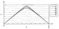
예를 들면, 도 7에 도시한 바와 같이, 각 중심축 AX를 지나는 선을 X축, X축과 직교하는 선을 Y축, 하나의 선모양 광원(10)의 중심축 AX를 X축의 원점으로 하고, 이 원점을 지나는 선 M1과 원점으로부터 P/2만큼 떨어진 곳(선모양 광원(10) 사이의 중심)을 지나는 선 M2 사이를 5개의 섹션(X1∼X5)으로 등간격으로 분할하고, 각각의 섹션에 포함되는 광학 시트(13)의 볼록부의 형상을 도 8에 도시한 형상으로 했을 때를 실시예 1로 한다. 그리고, 상기한 각 섹션에 포함되는 광학 시트(13)의 볼록부의 형상을 도 9에 도시한 형상으로 했을 때를 비교예 1로 한다. 다시 말해, 비교예 1의 볼록부의 배치는, 선모양 광원(10)과의 위치 관계에서, 실시예 1의 볼록부의 배치와 역{逆}으로 되어 있다.For example, as shown in FIG. 7, the line passing through each center axis AX is the X axis, the line orthogonal to the X axis is the Y axis, and the center axis AX of one
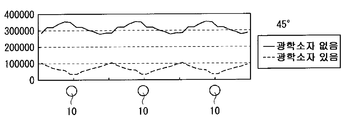
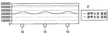
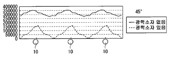
구체적으로는, 실시예 1에서는, 상대적으로 집광 작용이 강한 볼록부가 선모양 광원(10) 위에 형성되고, 상대적으로 집광 작용이 약한(혹은, 확산성이 강한) 볼록부가 선모양 광원(10)사이 위에 형성되어 있다. 다른 한편, 비교예 1에서는, 상대적으로 집광 작용이 약한(혹은, 확산성이 강한) 볼록부가 선모양 광원(10)사이 위에 형성되고, 상대적으로 집광 작용이 강한 볼록부가 선모양 광원(10) 위에 형성되어 있다. 또한, P/2≤x≤P에서는, 0≤x≤P/2에서의 형상을 반전시킨 볼록부가 배치되어 있으며, 각 볼록부는 선모양 광원(10)에 대응해서 주기적으로 배치되어 있는 것으로 한다. 그 때의 시뮬레이션 결과를 도 10∼도 13에 도시했다. 또한, 도 10은 실시예 1의 광학 시트를 이용했을 때와 없앴을 때의 정면 방향의 면내 휘도 분포를, 도 11은 실시예 1의 광학 시트를 이용했을 때와 없앴을 때의 기울기 방향의 면내 휘도 분포를, 도 12는 비교예 1의 광학 시트를 이용했을 때와 없앴을 때의 정면 방향의 면내 휘도 분포, 도 13은 비교예 1의 광학 시트를 이용했을 때와 없앴을 때의 기울기 방향의 면내 휘도 분포를 각각 도시한 것이다.Specifically, in Example 1, a convex portion having a relatively strong condensing action is formed on the linear
도 12∼도 13으로부터, 비교예 1의 광학 시트를 이용한 경우에는, 정면 방향 및 기울기 방향의 쌍방에서 휘도 얼룩이 커져 있는(다시 말해, 휘도 얼룩이 개선되어 있지 않은) 것을 알 수 있다. 한편, 도 10∼도 11로부터, 실시예 1의 광학 시트를 이용한 경우에는, 정면 방향 및 기울기 방향의 쌍방에서 휘도 얼룩이 작아져 있는 것을 알 수 있다. 따라서, 실시예 1과 같이, 광량이 많은 선모양 광원(10) 위에서, 상대적으로 집광 작용이 강한 볼록부에 의해서 집광함과 동시에, 광량이 적은 선모양 광원(10) 사이에서 상대적으로 집광 작용이 약한(혹은, 확산성이 강한) 볼록부에 의해서 확산하는 것에 의해서, 정면 방향 및 기울기 방향 모두 면내의 휘도 얼룩을 저감할 수가 있다.12-13, when the optical sheet of the comparative example 1 was used, it turns out that brightness unevenness is large (that is, brightness unevenness is not improved) in both a front direction and a tilt direction. On the other hand, when the optical sheet of Example 1 is used from FIGS. 10-11, it turns out that luminance unevenness is small in both a front direction and a tilt direction. Therefore, as in the first embodiment, on the linear
또, 본 실시형태에서, 제1 영역 R1과, 제2 영역 R2가 각각 평탄면을 가지고 있는 경우에, 식(4)를 만족시키고 있을 때에는, 제1 영역 R1 및 제2 영역 R2에 형성된 볼록부의 형상 및 크기가 서로 같았다고 해도, 식(1) 또는 식(5)을 만족시키게 된다. 따라서, 이와 같은 경우이더라도, 정면 방향 및 기울기 방향 모두 면내의 휘도 얼룩을 저감할 수가 있다.In the present embodiment, when the first region R1 and the second region R2 each have a flat surface, when the equation (4) is satisfied, the convex portions formed in the first region R1 and the second region R2 are satisfied. Even if the shape and the size are the same, equation (1) or equation (5) is satisfied. Therefore, even in such a case, in-plane luminance unevenness can be reduced in both the front direction and the inclination direction.
그런데, 일반적으로, 면내의 휘도 얼룩이 발생하는 것은, P/H를 크게 했을 때이다. P/H가 커지는 케이스는 두 개 있으며, 하나는 선모양 광원(10)과 확산판(12) 과의 거리를 좁게 해서 박형화했을 때이며, 또다른 하나는 선모양 광원(10)의 수를 줄여서 성등화{省燈化; thrifty lighting}했을 때이다. 본 실시형태의 표시 장치는, 이들 두 개의 케이스중 성등화에 적합하다. 본 실시형태에서는, 광학 시트(13)에서의 K1의 위치가 선모양 광원(10)과의 관계에서, 선모양 광원(10)의 배열 방향으로 어긋나면, 휘도 얼룩이 발생할 수 있다. 그러나, 성등화에 의해 선모양 광원(10) 끼리의 간격을 넓히는(일반적으로는, P〉30㎜) 경우에는, K1의 위치 어긋남에 의해서 발생하는 휘도 얼룩의 영향이 작고, 휘도 얼룩 저감의 효과가 감쇄될 우려가 거의 없다. 따라서, 본 실시형태에서는, 휘도 얼룩을 악화시키는 일없이, 효과적으로 성등화하는 것이 가능하다.By the way, generally, in-plane brightness | luminance unevenness generate | occur | produces when P / H is enlarged. There are two cases in which the P / H becomes large, one is when the distance between the linear
다음에, 본 실시형태의 광학 시트(13)의 형성 방법의 1예에 대해서 설명한다.Next, an example of the formation method of the
광학 시트(13)에 한정되지 않고, 시트모양의 광학 소자를 형성할 때에, 열가소성 수지를 이용해서 일체적으로 형성하는 경우나, 기재 위에 자외선 경화 수지를 전사해서, 형성하는 경우 등에는, 전사용 원반(금형)을 미리 작성해 두는 것이 필요하게 된다. 원반은, 예를 들면 금속 롤의 표면을, 전사하고 싶은 형상을 가지는 칼날로 절삭하는 것에 의해 작성가능하다. 이 때, 광학 시트(13)에 전사하는 볼록부의 형상이, 도 2에 도시한 바와 같이 복수 종류 있는 경우에는, 그 종류의 수만큼 칼날을 준비해 두지 않으면 안되어, 제조 코스트의 상승을 초래한다.Not limited to the
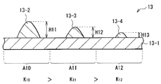
도 14의 (a), (b)에 도시한 바와 같이, 꼭대기부 부근에서의 접면의 각도가 40도 이하, 바닥부 부근에서의 접면의 각도가 40도 이상으로 되어 있는 칼날(2)을 준비하고, 도 15에 도시한 바와 같이, 절삭하는 장소에 따라 칼날(2)의 원반(3)에 대한 절삭 깊이를 바꾸는 것이 바람직하다. 그와 같이 해서 형성한 원반(3)을 이용해서, 도 16에 도시한 바와 같이, 기재(13-1) 위에, 절삭 깊이에 대응한 높이 및 형상을 가지는 볼록부(13-2, 13-3, 13-4)를 형성한 경우에는, 각 영역(A10, A11, A12)에서의, 리턴광이 발생하는 부분이 차지하는 비율(K10, K11, K12)을 달리 하는 것이 가능해진다. 이와 같이, 단일의 칼날(2)을 이용해서 원반(3)을 작성하는 것만으로, 광학 시트(13)를 작성할 수 있으므로, 제조 코스트의 상승을 억제할 수가 있다. 또, 이 경우에는, 볼록부의 높이가 장소에 따라서 다르므로, 광학 시트(13)가 , 볼록부 측에 배치된 다른 광학 소자와 달라붙는 것을 방지할 수도 있다.As shown to (a) and (b) of FIG. 14, the
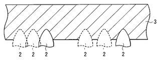
또, 예를 들면 꼭대기부 부근에서의 접면의 각도가 40도 이하, 바닥부 부근에서의 접면의 각도가 40도 이상으로 되어 있는 칼날(2)을 준비하고, 도 17에 도시한 바와 같이, 칼날(2)의 원반(3)에 대한 절삭폭(피치)을 바꾸도록 해도 좋다. 그와 같이 해서 형성한 원반(3)을 이용해서, 도 18에 도시한 바와 같이, 기재(13-1) 위에, 절삭폭에 대응한 피치를 가지는 복수의 볼록부(13-5)를 형성한 경우에도, 각 영역(A13, A14)에서의, 리턴광이 발생하는 부분이 차지하는 비율(K13, K14)을 달리 하는 것이 가능해진다. 이와 같이, 단일의 칼날(2)을 이용해서 원반(3)을 작성하는 것만으로, 광학 시트(13)를 작성할 수 있으므로, 제조 코스트의 상승을 억제할 수가 있다.Moreover, for example, the
[변형예][Modification]
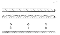
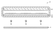
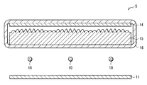
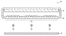
상기 실시형태에서는, 광학 시트(13)와 선모양 광원(10) 사이에 확산판(12)을 배치하고 있었지만, 도 19의 조명 장치(4)에 도시한 바와 같이, 확산판(12)을 광학 시트(13) 위에 배치해도 좋다. 단, 이와 같이 한 경우에는, 광학 시트(13)의 바로 아래에 선모양 광원(10)이 배치되게 되므로, 광학 시트(13)의 선모양 광원(10)에 대한 위치결정 정밀도를 높이는 궁리{ingenuity}를 실행해 두는 것이 바람직하다. 또, 도 20의 조명 장치(5)에 도시한 바와 같이, 확산판(12)과 마찬가지 기능을 가지는 기재의 광 사출측 표면에, 광학 시트(13)의 볼록부와 마찬가지 특징을 가지는 볼록부를 구비한 광학 시트(15)를 선모양 광원(10)의 바로 위에 설치하고, 그 위에 확산 시트(14)를 설치하도록 해도 좋다. 이 광학 시트(15)는, 예를 들면 용융 압출법{押出法; extrusion process}이나 사출 성형법 등의 방법을 이용해서 일괄해서 형성된 것이더라도 좋고, 예를 들면 확산판(12)의 표면에, 광학 시트(13)에 확산제를 포함시킨 것을 서로 붙이는 것에 의해 형성된 것이더라도 좋다.In the said embodiment, although the
또, 도 21, 도 22, 도 23에 도시한 바와 같이, 선모양 광원(10) 위에 배치된 각종 광학 소자(예를 들면, 확산판(12), 광학 시트(13), 확산 시트(14), 광학 시트(15) 등)를 감싸는 가요성{可撓性} 필름(16)을 설치하도록 해도 좋다. 이와 같이 한 경우에는, 선모양 광원(10) 위의 각종 광학 시트가 온도 변화에 따라 신축하는 양이 서로 다를 때이더라도, 각각의 광학 시트에 주름을 발생시키는 일없이, 각종 광학 소자를 조명 장치(1, 4, 5) 의 패키지(도시하지 않음)에 보존유지시킬 수가 있다. 도 22에 도시한 바와 같이, 확산판(12)의 이면(선모양 광원(10)측의 면)과 가요성 필름(16) 사이에 광학 시트(13)를 배치한 경우에는, 뒤틀림{反; warp}이나 휨{撓; deflection}을 방지하기 위해서 광학 시트(13)의 강성을 강하게 할 필요가 없으므로, 광학 시트(13)를 확산판(12)의 위면에 설치한 경우(상기 제1 실시형태의 경우)와 같은 정도로 광학 시트(13)를 얇게 할 수가 있다. 이것에 의해, 광학 시트(13)를 확산판(12)의 바로 아래에 설치한 경우이더라도, 조명 장치(4)를 박형화하는 것이 가능해진다. 또, 도 24에 도시한 바와 같이, 가요성 필름(16)에 광학 시트(13)의 볼록부와 마찬가지 특징을 가지는 볼록부를 설치하도록 해도 좋다. 이것에 의해, 조명 장치(4)를 더욱더 박형화하는 것이 가능해진다. 또, 가요성 필름(16)중 선모양 광원(10)으로부터의 광이 입사하는 광 입사 영역이나, 가요성 필름(16)중 선모양 광원(10)으로부터의 광이 광학 시트(13) 등을 투과해서 외부로 사출하는 광 사출 영역에, 확산 기능을 갖게 하거나, 입체 형상을 설치하거나 해도 좋다.21, 22, and 23, various optical elements (for example, the
[적용예][Application Example]
다음에, 상기 실시형태의 조명 장치(1)를 표시 장치에 적용한 경우에 대해서 설명한다. 또한, 이하에서는, 조명 장치(1)의 적용예에 대해서 설명하겠지만, 조명 장치(1) 대신에, 다른 조명 장치(4, 5)를 이용하는 것은 물론 가능하다.Next, the case where the illuminating
도 25는, 본 적용예에 관계된 표시 장치(6)의 단면 구성을 도시한 것이다. 이 표시 장치(6)는, 표시 패널(7)과, 표시 패널(7)의 배후에, 확산 시트(14)를 표시 패널 측을 향하여 배치된 조명 장치(1)를 구비하고 있으며, 표시 패널(7)의 표면이 관찰자(도시하지 않음) 측으로 향해져 있다.25 illustrates a cross-sectional structure of the
표시 패널(7)은, 도시하지 않지만, 관찰측의 투명 기판과 조명 장치(1)측의 투명 기판 사이에 액정층을 가지는 적층 구조로 되어 있다. 구체적으로는, 관찰측으로부터 차례로, 편광판, 투명 기판, 컬러 필터, 투명 전극, 배향막, 액정층, 배향막, 투명 화소 전극, 투명 기판 및 편광판을 가지고 있다.Although not shown, the
편광판은, 광학 셔터의 일종이며, 어떤 일정의 진동 방향의 광(편광)만을 통과시킨다. 이들 편광판은 각각, 편광축이 서로 90도 다르도록 배치되어 있으며, 이것에 의해 조명 장치(1)로부터의 사출광이, 액정층을 거쳐서 투과하거나, 혹은 차단되도록 되어 있다. 투명 기판은, 가시광에 대해서 투명한 기판, 예를 들면 판 유리로 이루어진다. 또한, 조명 장치(1)측의 투명 기판에는, 투명 화소 전극에 전기적으로 접속된 구동 소자로서의 TFT(Thin Film Transistor; 박막 트랜지스터) 및 배선 등을 포함하는 액티브형 구동 회로가 형성되어 있다. 컬러 필터는, 조명 장치(1)로부터의 사출광을 예를 들면 빨강(R), 초록(G) 및 파랑(B)의 삼원색으로 각각 색분리하기 위한 컬러 필터를 배열해서 구성되어 있다. 투명 전극은, 예를 들면 ITO(Indium Tin Oxide; 산화 인듐 주석)로 이루어지고, 공통의 대향 전극으로서 기능한다. 배향막은, 예를 들면 폴리이미드 등의 고분자 재료로 이루어지고, 액정에 대해서 배향 처리를 행한다. 액정층은, 예를 들면 VA(Vertical Alignment) 모드, TN(Twisted Nematic) 모드 또는 STN(Super Twisted Nematic) 모드의 액정으로 이루어지고, 구동 회로로부터의 인가 전압에 의해, 조명 장치(1)로부터의 사출광을 각 화소마다 투과 또는 차단하는 기능을 가진다. 투명 화소 전극은, 예를 들면 ITO로 이루어지고, 각 화소마다의 전극으로서 기능한다.A polarizing plate is a kind of optical shutter and passes only the light (polarization) of a certain vibration direction. These polarizing plates are arrange | positioned so that a polarization axis may mutually differ 90 degrees, respectively, and the light emitted from the illuminating
다음에, 본 적용예에 관계된 표시 장치(6)에서의 작용에 대해서 설명한다. 조명 장치(1)내의 각 선모양 광원(10)으로부터 사출된 광은 원하는 정면 휘도, 면내 휘도 분포 및 시야각 등을 가지는 광으로 조정된 후, 표시 패널(7)의 이면을 조명한다. 표시 패널(7)의 이면을 조명한 광은, 표시 패널(7)에서 변조되고, 화상광으로서 표시 패널(7)의 표면으로부터 관찰자 측으로 사출된다.Next, the operation of the
본 적용예에 관계된 표시 장치(6)에서는, 조명 장치(1)에서 식(1) 또는 식(5)를 만족시키고 있으므로, 표시 패널(7)의 이면을 조명하는 조명광의 휘도 얼룩의 시야각 의존성이 낮게 되어 있다. 이것에 의해, 관찰자가 표시 장치(6)를 비스듬히{기울기 방향}에서 바라본 경우이더라도, 면내의 휘도 얼룩을 관찰자에게 그다지 느끼게 하지 않도록 할 수가 있다.In the
이상, 실시형태, 변형예 및 적용예를 들어 본 발명을 설명했지만, 본 발명은 실시형태 등에 한정되는 것은 아니며, 갖가지 변형이 가능하다.As mentioned above, although this invention was demonstrated based on embodiment, a modification, and an application example, this invention is not limited to embodiment etc., A various deformation | transformation is possible.
예를 들면, 상기 실시형태 등에서는, 표시 장치(1, 4, 5)에서, 광학 시트(13, 15)의 광 사출측에는, 확산 기능을 가지는 광학 소자밖에 배치되어 있지 않았지만, 다른 기능을 가지는 광학 소자를 배치해도 좋다. 예를 들면, 선모양 광원(10)의 바로 위에 광학 시트(13)를 배치한 경우에는, 광학 시트(13, 15)의 광 사출측에 프리즘 시트를 배치하는 것이 바람직하다. 광학 시트(13)의 선모양 광원(10)에 대한 위치 어긋남이 생긴 경우이더라도, 프리즘 시트에서의 리턴광이 조명 장치(4)내를 순환하는 리사이클 효과에 의해서, 위치 어긋남에 기인하는 표시 장치(4)의 광학 특성의 저하를 완화할 수가 있다.
For example, in the said embodiment etc., in the
1, 4, 5: 조명 장치, 6: 표시 장치, 7: 표시 패널, 10: 선모양 광원, 10A: 면, 11: 반사판, 12: 확산판, 13: 광학 시트, 13A, 13B, 13C: 볼록부, 14: 확산 시트, 15: 광학 시트, 16: 가요성 필름.1, 4, 5: lighting device, 6: display device, 7: display panel, 10: linear light source, 10A: face, 11: reflector, 12: diffuser, 13: optical sheet, 13A, 13B, 13C: convex Part 14: Diffusion sheet, 15 Optical sheet, 16: Flexible film.
Claims (28)
상기 각 선모양 광원과 대향 배치된 반사판과,
상기 하나의 면에 관해서 상기 반사판의 반대측에 배치된 평판모양의 확산 부재와,
상기 각 선모양 광원과 상기 확산 부재 사이에 배치된 광학 부재
를 구비하고,
상기 광학 부재는,
상기 하나의 면에 평행한 광 입사면과,
상기 각 선모양 광원과 상기 하나의 면의 법선 방향으로 대향하는 제1 영역에 제1 입체 구조를 가짐과 동시에, 하나의 선모양 광원과 상기 하나의 선모양 광원에 인접하는 다른 선모양 광원 사이의 중간 영역과 상기 하나의 면의 법선 방향으로 대향하는 제2 영역에 제2 입체 구조를 가지는 광 사출면
을 가지고,
상기 각 선모양 광원으로부터 상기 광 입사면에 수직으로 입사한 광이 상기 제1 입체 구조에 의해서 전{全}반사되어 상기 반사판으로 향하는 리턴광{戾光; return light}을 발생시키는 제1 부분이, 상기 광학 부재를 상기 하나의 면의 법선 방향에서 보았을 때에 상기 제1 영역에서 차지하는 비율을 K1로 하고, 상기 각 선모양 광원으로부터 상기 광 입사면에 수직으로 입사한 광이 상기 제2 입체 구조에 의해서 전{全}반사되어 상기 반사판으로 향하는 리턴광을 발생시키는 제2 부분이, 상기 광학 부재를 상기 하나의 면의 법선 방향에서 보았을 때에 상기 제2 영역에서 차지하는 비율을 K2로 했을 때, K1 및 K2 는 이하의 식을 만족시키는 조명 장치.
K1-K2〉0A plurality of linear light sources arranged such that each central axis is parallel to each other and included in one plane;
A reflector disposed to face each of the linear light sources;
A plate-shaped diffusion member disposed on an opposite side of the reflecting plate with respect to the one surface;
An optical member disposed between each of the linear light sources and the diffusion member
And
The optical member,
A light incident surface parallel to the one surface;
A first three-dimensional structure in a first region facing each of the linear light sources and the one surface in the normal direction, and between one linear light source and another linear light source adjacent to the one linear light source A light emitting surface having a second three-dimensional structure in a second region facing the middle region in the normal direction of the one surface
To have,
Return light which is incident on the light incidence plane perpendicularly from the respective linear light sources to the reflection plate by being totally reflected by the first three-dimensional structure; The first portion generating the return light} has a ratio of K1 in the first region when the optical member is viewed in the normal direction of the one surface, and is perpendicular to the light incident surface from the respective linear light sources. A second portion in which incident light is totally reflected by the second three-dimensional structure to generate return light directed to the reflecting plate is formed in the second region when the optical member is viewed from the normal direction of the one surface. When the ratio to occupy is K2, K1 and K2 satisfy | fill the following formula.
K1-K2〉 0
상기 제1 입체 구조에 접하는 접선과 상기 하나의 면이 이루는 각을 ψ1, 상기 제2 입체 구조에 접하는 접선과 상기 하나의 면이 이루는 각을 ψ2로 하면, ψ1 및 ψ2는, 상기 제1 부분 및 상기 제2 부분에서 이하의 식을 만족시키는 조명 장치.
39≤ψ1≤69
39≤ψ2≤69The method of claim 1,
When the angle between the tangent tangent contacting the first solid structure and the one surface is ψ1, and the angle between the tangent tangent tangent to the second solid structure and the one surface is ψ2, ψ1 and ψ2 are the first portion and Lighting device which satisfies the following formula in the said 2nd part.
39≤ψ1≤69
39≤ψ2≤69
K1 및 K2는 이하의 식을 만족시키는 조명 장치.
K1-K2≥0.03The method of claim 1,
K1 and K2 satisfy | fill the following formula | equation.
K1-K2≥0.03
K1 및 K2는 이하의 식을 만족시키는 조명 장치.
K1-K2≥0.06The method of claim 1,
K1 and K2 satisfy | fill the following formula | equation.
K1-K2≥0.06
K1 및 K2는 이하의 식을 만족시키는 조명 장치.
K1-K2≥0.12The method of claim 1,
K1 and K2 satisfy | fill the following formula | equation.
K1-K2≥0.12
K1 및 K2는 이하의 식을 만족시키는 조명 장치.
K1-K2≥0.15The method of claim 1,
K1 and K2 satisfy | fill the following formula | equation.
K1-K2≥0.15
K1 및 K2는 이하의 식을 만족시키는 조명 장치.
K1-K2≥0.18The method of claim 1,
K1 and K2 satisfy | fill the following formula | equation.
K1-K2≥0.18
K2가 제로로 되어 있는 조명 장치.The method of claim 1,
Lighting device with K2 zero.
상기 선모양 광원끼리의 간격이 30㎜ 이상으로 되어 있는 조명 장치.The method of claim 1,
The illuminating device in which the space | interval of the said linear light sources is 30 mm or more.
상기 제1 입체 구조는 선모양 또는 뿔체모양{錐體狀}의 복수의 제1 볼록부를 가지고,
상기 제2 입체 구조는 선모양 또는 뿔체모양의 복수의 제2 볼록부를 가지는 조명 장치.The method of claim 1,
The first three-dimensional structure has a plurality of first convex portions having a line or horn shape,
The second three-dimensional structure has a plurality of second convex portion of the line or horn shape.
상기 제1 볼록부에 접하는 접선과 상기 하나의 면이 이루는 각을 ψ1, 상기 제2 볼록부에 접하는 접선과 상기 하나의 면이 이루는 각을 ψ2로 하면, ψ1 및 ψ2는, 상기 볼록부의 꼭대기부로부터 바닥부로 향함에 따라서 연속적 또는 단속적으로 커져 있는 조명 장치.The method of claim 1,
When the angle formed by the tangent contacting the first convex portion and the one surface is ψ1, and the angle formed by the tangent contacting the second convex portion and the one surface is ψ2, ψ1 and ψ2 are the top of the convex portion. A lighting device that grows continuously or intermittently as it faces from the floor to the floor.
상기 제1 볼록부 및 상기 제2 볼록부는 경사 평면을 가지는 조명 장치.The method of claim 10,
And the first convex portion and the second convex portion have an inclined plane.
상기 제1 볼록부 및 상기 제2 볼록부는 비구면을 가지는 조명 장치.The method of claim 10,
And the first convex portion and the second convex portion have an aspherical surface.
상기 제1 볼록부는 경사 평면을 가지고,
상기 제2 볼록부는 비구면을 가지는 조명 장치.The method of claim 10,
The first convex portion has an inclined plane,
The second convex portion has an aspherical surface.
상기 제1 볼록부 및 상기 제2 볼록부는, 꼭대기부 및 그 근방에 볼록모양의 곡면을 가짐과 동시에, 그 이외의 부분에 상기 곡면과 매끄럽게 연속하는 경사 평면을 가지는 조명 장치.The method of claim 10,
The said 1st convex part and the said 2nd convex part have a convex-shaped curved surface in the top part and its vicinity, and have the inclined plane which is smoothly continuous with the said curved surface in other parts.
상기 제1 볼록부의 곡면의 곡률이 상기 제2 볼록부의 곡면의 곡률보다도 작게 되어 있는 조명 장치.16. The method of claim 15,
The curvature of the curved surface of a said 1st convex part is smaller than the curvature of the curved surface of a said 2nd convex part.
상기 제1 볼록부의 높이가 상기 제2 볼록부의 높이보다도 높게 되어 있는 조명 장치.The method of claim 10,
An illuminating device whose height of said 1st convex part becomes higher than the height of said 2nd convex part.
상기 제1 입체 구조 및 상기 제2 입체 구조는, 상기 하나의 면과 평행한 1 또는 복수의 평탄면을 가지고,
상기 제1 입체 구조의 평탄면이, 상기 광학 부재를 상기 하나의 면의 법선 방향에서 보았을 때에 상기 제1 영역에서 차지하는 비율을 K3으로 하고, 상기 제2 입체 구조의 평탄면이, 상기 광학 부재를 상기 하나의 면의 법선 방향에서 보았을 때에 상기 제2 영역에서 차지하는 비율을 K4로 했을 때, K3 및 K4는 이하의 식을 만족시키는 조명 장치.
K4-K3〉0The method of claim 10,
The first three-dimensional structure and the second three-dimensional structure has one or a plurality of flat surfaces parallel to the one surface,
The flat surface of the first three-dimensional structure has a ratio of K3 in the first region when the optical member is viewed from the normal direction of the one surface, and the flat surface of the second three-dimensional structure is the optical member. The lighting apparatus which satisfy | fills the following formula when K4 and K4 satisfy | fill the ratio which occupies for the said 2nd area | region in the normal direction of the said one surface as K4.
K4-K3〉 0
상기 평탄면은 상기 제1 볼록부 및 상기 제2 볼록부의 비형성 영역에 형성되어 있는 조명 장치.The method of claim 18,
And said planar surface is formed in an unformed region of said first convex portion and said second convex portion.
상기 평탄면은 상기 제2 볼록부의 꼭대기부에도 형성되어 있는 조명 장치.The method of claim 19,
The flat surface is also formed on top of the second convex portion.
상기 확산 부재는 확산판인 조명 장치.The method of claim 1,
And said diffusion member is a diffusion plate.
상기 광학 부재와 상기 각 선모양 광원 사이에 확산판을 구비하는 조명 장치.The method of claim 1,
An illuminating device provided with a diffuser plate between the said optical member and each said linear light source.
상기 확산 부재는 확산 시트인 조명 장치.The method of claim 22,
And said diffusion member is a diffusion sheet.
상기 확산 부재 및 상기 광학 부재는 서로 일체로 형성되어 있는 조명 장치.The method of claim 1,
And the diffusion member and the optical member are integrally formed with each other.
상기 확산 부재 및 상기 광학 부재를 감싸는 가요성 필름을 구비하는 조명 장치.The method of claim 1,
And a flexible film surrounding the diffusion member and the optical member.
상기 가요성 필름은 상기 선모양 광원으로부터의 광이 입사하는 광 입사 영역에 확산 기능을 가지는 조명 장치.The method of claim 25,
And said flexible film has a diffusion function in a light incident region where light from said linear light source is incident.
상기 가요성 필름은, 상기 선모양 광원으로부터의 광이 입사하는 광 입사 영역의 표면에 입체 형상을 가지는 조명 장치.The method of claim 25,
The said flexible film has a three-dimensional shape on the surface of the light-incidence area | region to which the light from the said linear light source injects.
상기 패널을 조명하는 조명 장치
를 구비하고,
상기 조명 장치는,
각각의 중심축이 서로 평행하게 됨과 동시에 하나의 면내에 포함되도록 배치된 복수의 선모양 광원과,
상기 각 선모양 광원과 대향 배치된 반사판과,
상기 하나의 면에 관해서 상기 반사판의 반대측에 배치된 평판모양의 확산 부재와,
상기 각 선모양 광원과 상기 확산 부재 사이에 배치된 광학 부재
를 가지고,
상기 광학 부재는,
상기 하나의 면에 평행한 광 입사면과,
상기 각 선모양 광원과 상기 하나의 면의 법선 방향으로 대향하는 제1 영역에 제1 입체 구조를 가짐과 동시에, 하나의 선모양 광원과 상기 하나의 선모양 광원에 인접하는 다른 선모양 광원 사이의 중간 영역과 상기 하나의 면의 법선 방향으로 대향하는 제2 영역에 제2 입체 구조를 가지는 광 사출면
을 가지고,
상기 각 선모양 광원으로부터 상기 광 입사면에 수직으로 입사한 광이 상기 제1 입체 구조에 의해서 전반사되어 상기 반사판으로 향하는 리턴광을 발생시키는 제1 부분이, 상기 광학 부재를 상기 하나의 면의 법선 방향에서 보았을 때에 상기 제1 영역에서 차지하는 비율을 K1로 하고, 상기 각 선모양 광원으로부터 상기 광 입사면에 수직으로 입사한 광이 상기 제2 입체 구조에 의해서 전반사되어 상기 반사판으로 향하는 리턴광을 발생시키는 제2 부분이, 상기 광학 부재를 상기 하나의 면의 법선 방향에서 보았을 때에 상기 제2 영역에서 차지하는 비율을 K2로 했을 때, K1 및 K2는 이하의 식을 만족시키는 표시 장치.
K1-K2〉0A panel driven based on an image signal,
Lighting device for illuminating the panel
And
The lighting device,
A plurality of linear light sources arranged such that each central axis is parallel to each other and included in one plane;
A reflector disposed to face each of the linear light sources;
A plate-shaped diffusion member disposed on an opposite side of the reflecting plate with respect to the one surface;
An optical member disposed between each of the linear light sources and the diffusion member
Take it,
The optical member,
A light incident surface parallel to the one surface;
A first three-dimensional structure in a first region facing each of the linear light sources and the one surface in the normal direction, and between one linear light source and another linear light source adjacent to the one linear light source A light emitting surface having a second three-dimensional structure in a second region facing the middle region in the normal direction of the one surface
To have,
A first portion in which light incident perpendicularly to the light incidence plane from each of the line light sources is totally reflected by the first three-dimensional structure to generate a return light directed to the reflecting plate is normal to the one surface of the optical member. The ratio occupied in the first region when viewed from the direction is K1, and light incident perpendicularly to the light incident surface from each of the linear light sources is totally reflected by the second three-dimensional structure to generate return light directed to the reflecting plate. A display device according to claim 1, wherein K1 and K2 satisfy the following expression when the second portion to be assumed assumes the ratio of the optical member in the second area when the optical member is viewed in the normal direction of the one surface.
K1-K2〉 0
Applications Claiming Priority (2)
| Application Number | Priority Date | Filing Date | Title |
|---|---|---|---|
| JP2008135803A JP5071675B2 (en) | 2008-05-23 | 2008-05-23 | Illumination device and display device |
| JPJP-P-2008-135803 | 2008-05-23 |
Publications (1)
| Publication Number | Publication Date |
|---|---|
| KR20110009070A true KR20110009070A (en) | 2011-01-27 |
Family
ID=41340154
Family Applications (1)
| Application Number | Title | Priority Date | Filing Date |
|---|---|---|---|
| KR1020107000570A KR20110009070A (en) | 2008-05-23 | 2009-05-20 | Illumination device and display device |
Country Status (8)
| Country | Link |
|---|---|
| US (1) | US8246188B2 (en) |
| EP (1) | EP2278213A4 (en) |
| JP (1) | JP5071675B2 (en) |
| KR (1) | KR20110009070A (en) |
| CN (1) | CN101755166B (en) |
| BR (1) | BRPI0903906A2 (en) |
| TW (1) | TW201013116A (en) |
| WO (1) | WO2009142226A1 (en) |
Families Citing this family (11)
| Publication number | Priority date | Publication date | Assignee | Title |
|---|---|---|---|---|
| JP5295721B2 (en) * | 2008-11-04 | 2013-09-18 | 旭化成株式会社 | Backlight unit |
| JP5379728B2 (en) * | 2009-03-25 | 2013-12-25 | 旭化成株式会社 | Light control unit |
| JP5927536B2 (en) * | 2011-07-05 | 2016-06-01 | パナソニックIpマネジメント株式会社 | Light guide plate and surface light source device |
| KR102094806B1 (en) * | 2013-06-19 | 2020-03-31 | 엘지디스플레이 주식회사 | Light emitting diode package and liquid crystal display device having the same |
| JP2018527711A (en) * | 2015-09-02 | 2018-09-20 | ルミレッズ ホールディング ベーフェー | LED module and lighting module |
| JP2019139851A (en) * | 2018-02-06 | 2019-08-22 | オムロン株式会社 | Light guide plate, surface light source device, display device, and electronic apparatus |
| KR102551354B1 (en) * | 2018-04-20 | 2023-07-04 | 삼성전자 주식회사 | Semiconductor light emitting devices and methods of manufacturing the same |
| CN109270735B (en) * | 2018-10-25 | 2021-08-17 | 厦门天马微电子有限公司 | Backlight module and display device |
| WO2020236971A1 (en) * | 2019-05-20 | 2020-11-26 | Abl Ip Holding Llc | Micro-structured optical sheet and panel light assembly using same |
| US11624495B2 (en) | 2019-05-20 | 2023-04-11 | Abl Ip Holding Llc | Systems and methods for stabilizing optical sheets in luminaires |
| USD982224S1 (en) | 2021-03-25 | 2023-03-28 | Abl Ip Holding Llc | Planar optical panel for a light fixture |
Family Cites Families (13)
| Publication number | Priority date | Publication date | Assignee | Title |
|---|---|---|---|---|
| JPH09236803A (en) * | 1996-02-28 | 1997-09-09 | Victor Co Of Japan Ltd | Back light for liquid crystal display |
| US5995288A (en) | 1997-04-22 | 1999-11-30 | Dai Nippon Printing Co., Ltd. | Optical sheet optical sheet lamination light source device, and light-transmissive type display apparatus |
| KR100897745B1 (en) * | 2002-06-26 | 2009-05-15 | 삼성전자주식회사 | Back light assembly and direct type liquid crystal display |
| TWI364600B (en) * | 2004-04-12 | 2012-05-21 | Kuraray Co | An illumination device an image display device using the illumination device and a light diffusing board used by the devices |
| JP4499519B2 (en) * | 2004-07-12 | 2010-07-07 | 大日本印刷株式会社 | Diffusion sheet, surface light source device, transmissive display device |
| US20060204720A1 (en) | 2004-12-23 | 2006-09-14 | Biernath Rolf W | Uniaxially oriented birefringent article having a structured surface |
| KR101158893B1 (en) * | 2005-06-09 | 2012-06-25 | 삼성전자주식회사 | Optical member, backlight assembly having the same and liquid crystal display device having the same |
| TW200708853A (en) * | 2005-08-30 | 2007-03-01 | Ind Tech Res Inst | Light-guide plate and the backlight module having the same |
| JP4631628B2 (en) * | 2005-09-13 | 2011-02-16 | 日本電気株式会社 | Lighting device and display device |
| US20070110386A1 (en) * | 2005-11-12 | 2007-05-17 | Tien-Hon Chiang | Device having combined diffusing, collimating, and color mixing light control function |
| JP5170988B2 (en) | 2006-07-03 | 2013-03-27 | 株式会社ジャパンディスプレイイースト | Liquid crystal display |
| TWI346813B (en) * | 2006-10-14 | 2011-08-11 | Au Optronics Corp | Diffuser plate and backlight module using the same |
| JP5493312B2 (en) * | 2008-08-22 | 2014-05-14 | ソニー株式会社 | Surface light emitting device and image display device |
-
2008
- 2008-05-23 JP JP2008135803A patent/JP5071675B2/en not_active Expired - Fee Related
-
2009
- 2009-05-20 BR BRPI0903906-6A patent/BRPI0903906A2/en not_active IP Right Cessation
- 2009-05-20 CN CN2009801000044A patent/CN101755166B/en not_active Expired - Fee Related
- 2009-05-20 WO PCT/JP2009/059247 patent/WO2009142226A1/en active Application Filing
- 2009-05-20 US US12/669,396 patent/US8246188B2/en not_active Expired - Fee Related
- 2009-05-20 KR KR1020107000570A patent/KR20110009070A/en not_active Application Discontinuation
- 2009-05-20 EP EP09750588A patent/EP2278213A4/en not_active Withdrawn
- 2009-05-22 TW TW098117124A patent/TW201013116A/en not_active IP Right Cessation
Also Published As
| Publication number | Publication date |
|---|---|
| TWI370218B (en) | 2012-08-11 |
| TW201013116A (en) | 2010-04-01 |
| US8246188B2 (en) | 2012-08-21 |
| JP5071675B2 (en) | 2012-11-14 |
| EP2278213A1 (en) | 2011-01-26 |
| BRPI0903906A2 (en) | 2015-06-30 |
| WO2009142226A1 (en) | 2009-11-26 |
| CN101755166A (en) | 2010-06-23 |
| EP2278213A4 (en) | 2011-06-22 |
| JP2009283365A (en) | 2009-12-03 |
| US20100195314A1 (en) | 2010-08-05 |
| CN101755166B (en) | 2013-03-13 |
Similar Documents
| Publication | Publication Date | Title |
|---|---|---|
| KR102199264B1 (en) | Optical sheet, backlight unit, liquid crystal display and information equipment | |
| KR20110009070A (en) | Illumination device and display device | |
| EP1933178B1 (en) | Optical sheet and method for fabricating the same | |
| JP6098064B2 (en) | Display device and lighting device | |
| US8780300B2 (en) | Optical member, light source apparatus, display apparatus, and terminal apparatus | |
| JP5991053B2 (en) | Display device and lighting device | |
| KR100903028B1 (en) | Light guide panel comprising wedge type rear prism for back light unit of tft-lcd | |
| EP3264146B1 (en) | Display device and television receiver with laminated optical member. | |
| KR101096901B1 (en) | Optical sheet, surface light source device and transmissive display device | |
| US8016450B2 (en) | Illuminating apparatus and display apparatus | |
| JP2008145550A (en) | Optical sheet and display device | |
| KR20110097642A (en) | Optical sheet stack body, illuminating device, and display device | |
| US8118469B2 (en) | Surface illuminating device and image display apparatus | |
| KR101065181B1 (en) | Substrate and liquid crystal display including the same | |
| US20070229729A1 (en) | Liquid crystal display device | |
| KR102355828B1 (en) | Display Device having Multiple Display Panel | |
| JP2015069014A (en) | Light control sheet and display device | |
| WO2023145199A1 (en) | Optical sheet laminate, backlight unit, liquid crystal display device, information equipment, and production method for backlight unit | |
| WO2023282055A1 (en) | Optical sheet laminate, backlight unit, liquid crystal display device, information equipment, and production method for backlight unit | |
| JP2024056804A (en) | Light diffusion sheet | |
| KR102081114B1 (en) | Condensing sheet, backlight unit and liquid crystal display device using the same | |
| JP2023125175A (en) | Luminaire and display device | |
| JP2012027423A (en) | Optical sheet, optical sheet laminate, backlight unit and display device | |
| KR20100068102A (en) | Liquid crystal display device | |
| JP2009122257A (en) | Optical sheet, backlight unit provided with the same and display device |
Legal Events
| Date | Code | Title | Description |
|---|---|---|---|
| WITN | Application deemed withdrawn, e.g. because no request for examination was filed or no examination fee was paid |