KR20110008839A - Coupling device and valve apparatus having the same - Google Patents
Coupling device and valve apparatus having the same Download PDFInfo
- Publication number
- KR20110008839A KR20110008839A KR1020090066375A KR20090066375A KR20110008839A KR 20110008839 A KR20110008839 A KR 20110008839A KR 1020090066375 A KR1020090066375 A KR 1020090066375A KR 20090066375 A KR20090066375 A KR 20090066375A KR 20110008839 A KR20110008839 A KR 20110008839A
- Authority
- KR
- South Korea
- Prior art keywords
- coupling
- valve
- rotation angle
- coupling mechanism
- actuator
- Prior art date
Links
Images


Classifications
-
- F—MECHANICAL ENGINEERING; LIGHTING; HEATING; WEAPONS; BLASTING
- F16—ENGINEERING ELEMENTS AND UNITS; GENERAL MEASURES FOR PRODUCING AND MAINTAINING EFFECTIVE FUNCTIONING OF MACHINES OR INSTALLATIONS; THERMAL INSULATION IN GENERAL
- F16K—VALVES; TAPS; COCKS; ACTUATING-FLOATS; DEVICES FOR VENTING OR AERATING
- F16K31/00—Actuating devices; Operating means; Releasing devices
- F16K31/12—Actuating devices; Operating means; Releasing devices actuated by fluid
- F16K31/122—Actuating devices; Operating means; Releasing devices actuated by fluid the fluid acting on a piston
-
- F—MECHANICAL ENGINEERING; LIGHTING; HEATING; WEAPONS; BLASTING
- F16—ENGINEERING ELEMENTS AND UNITS; GENERAL MEASURES FOR PRODUCING AND MAINTAINING EFFECTIVE FUNCTIONING OF MACHINES OR INSTALLATIONS; THERMAL INSULATION IN GENERAL
- F16K—VALVES; TAPS; COCKS; ACTUATING-FLOATS; DEVICES FOR VENTING OR AERATING
- F16K27/00—Construction of housing; Use of materials therefor
-
- F—MECHANICAL ENGINEERING; LIGHTING; HEATING; WEAPONS; BLASTING
- F16—ENGINEERING ELEMENTS AND UNITS; GENERAL MEASURES FOR PRODUCING AND MAINTAINING EFFECTIVE FUNCTIONING OF MACHINES OR INSTALLATIONS; THERMAL INSULATION IN GENERAL
- F16K—VALVES; TAPS; COCKS; ACTUATING-FLOATS; DEVICES FOR VENTING OR AERATING
- F16K31/00—Actuating devices; Operating means; Releasing devices
- F16K31/44—Mechanical actuating means
- F16K31/52—Mechanical actuating means with crank, eccentric, or cam
- F16K31/524—Mechanical actuating means with crank, eccentric, or cam with a cam
-
- F—MECHANICAL ENGINEERING; LIGHTING; HEATING; WEAPONS; BLASTING
- F16—ENGINEERING ELEMENTS AND UNITS; GENERAL MEASURES FOR PRODUCING AND MAINTAINING EFFECTIVE FUNCTIONING OF MACHINES OR INSTALLATIONS; THERMAL INSULATION IN GENERAL
- F16K—VALVES; TAPS; COCKS; ACTUATING-FLOATS; DEVICES FOR VENTING OR AERATING
- F16K31/00—Actuating devices; Operating means; Releasing devices
- F16K31/44—Mechanical actuating means
- F16K31/60—Handles
-
- F—MECHANICAL ENGINEERING; LIGHTING; HEATING; WEAPONS; BLASTING
- F16—ENGINEERING ELEMENTS AND UNITS; GENERAL MEASURES FOR PRODUCING AND MAINTAINING EFFECTIVE FUNCTIONING OF MACHINES OR INSTALLATIONS; THERMAL INSULATION IN GENERAL
- F16K—VALVES; TAPS; COCKS; ACTUATING-FLOATS; DEVICES FOR VENTING OR AERATING
- F16K47/00—Means in valves for absorbing fluid energy
- F16K47/02—Means in valves for absorbing fluid energy for preventing water-hammer or noise
- F16K47/023—Means in valves for absorbing fluid energy for preventing water-hammer or noise for preventing water-hammer, e.g. damping of the valve movement
Abstract
Description
본 발명은 다단 회동형 커플링 기구 및 이를 포함하는 밸브 장치에 관한 것이며, 더욱 상세하게는 파이프 라인에 설치되는 밸브를 커플링 기구를 이용하는 간단한 구조변경을 통하여 다단으로 개폐할 수 있도록 함으로써, 밸브 급속 폐쇄에 따른 워터 햄머(수 충격) 현상 등을 제거할 수 있도록 하고, 이에 따라 밸브는 물론, 파이프 라인의 사용 수명을 연장시키고, 특히 간단한 구조로서 설치 시공을 용이하게 하는 커플링 기구 및 이를 포함하는 밸브 장치에 관한 것이다.The present invention relates to a multi-stage rotating coupling mechanism and a valve device including the same. More particularly, the valve installed in the pipeline can be opened and closed in multiple stages through a simple structural change using the coupling mechanism. Coupling mechanism and the coupling mechanism to make it possible to eliminate the water hammer (water shock) phenomenon due to the closing, thereby extending the service life of the pipeline, as well as the valve, and particularly easy installation It relates to a valve device.
각종 산업체(공장)에는 공정상 필요한 고압수, 냉각수나 생산과정에서 발생되는 유해가스나 기타 원료인 분말 등을 이송하는 여러 종류의 파이프 라인이 설치되고, 이와 같은 파이프 라인에는 구간마다 또는 필요한 위치에 라인을 개폐시키는 밸브들이 구비된다.Various industries (plants) are equipped with various types of pipelines for transporting high pressure water, cooling water, and harmful gases or other raw powders generated during the production process. Valves are provided to open and close the line.
예를 들어, 별도의 도면으로 도시하지는 않았지만, 밸브 바디가 파이프 사이에 설치되고, 밸브 바디내의 회동축에 설치된 디스크가 회전하면서 파이프(관)를 밀폐 또는 개방시키는 것이다.For example, although not shown in a separate drawing, a valve body is installed between pipes, and a disk installed on a rotation shaft in the valve body rotates to seal or open a pipe (pipe).
따라서, 대부분의 파이프 라인에 설치된 밸브에는 밸브 회동축을 회전 구동시키는 액츄에이터가 연계 설치되거나, 작업자가 수작업으로 조작하는 핸들들이 연계되어 있다.Therefore, a valve installed in most pipelines is provided with an actuator for rotationally driving the valve rotation shaft, or handles manually operated by an operator.
한편, 작동 조작을 위하여 밸브에 연계되는 액츄에이터 중 대표적인 것이 로터리 액츄에이터(Rotary Type Actuator)이다.(도 4,5의 110,120 참조)On the other hand, a representative of the actuators linked to the valve for operation operation is a rotary actuator (Rotary Type Actuator) (see 110, 120 of Figs. 4, 5).
그러나, 알려진 종래의 로터리 액츄에이터는 밸브 회동축과 연계되어 이를 회전 구동시키는 구동축의 회전각 조정은 불가능한 것이었다.However, known conventional rotary actuators have been impossible to adjust the rotation angle of the drive shaft which is linked with the valve rotation shaft and driven to rotate it.
즉, 알려진 대부분의 로터리 액츄에이터는 0°또는 90°만의 회전각만을 구현하기 때문에, 이와 같은 하나의 로터리 액츄에이터와 연계된 밸브도 그 내부 디스크의 회동각도는 0°또는 90°중 하나이고, 따라서 밸브의 개폐가 한번에 구현되는 것이다.That is, since most known rotary actuators implement only a rotation angle of only 0 ° or 90 °, even a valve associated with such a rotary actuator has an angle of rotation of the internal disk of 0 ° or 90 °, so the valve The opening and closing of is implemented at once.
그런데, 고압수가 통과하는 파이프 라인에서 개방 중이던 밸브 디스크가 회동하여 0°-> 90°로 한번에 급속 폐쇄되면, 워터 햄머 즉, 수 충격 현상이 발생된다.However, when the valve disc, which is open in the pipeline through which the high pressure water passes, is rapidly closed at a time from 0 ° to 90 °, a water hammer, that is, a water shock phenomenon occurs.
따라서, 밸브 수명이 단축됨은 물론, 파이프 라인의 정상 가동에도 영향을 미치게 될 것이다.Therefore, the valve life will be shortened, as well as affect the normal operation of the pipeline.
그런데, 앞에서 설명한 바와 같이, 밸브 디스크를 0°-> 45°-> 90°의 적어도 2단으로 개폐되도록 하기 위하여, 로터리 액츄에이터를 2단으로 사용하여도, 축 연결부의 구조 변경 없이는 상기와 같은 디스크의 다단 개폐는 불가능한 것이다.However, as described above, in order to open and close the valve disc in at least two stages of 0 °-> 45 °-> 90 °, even if the rotary actuator is used in two stages, the disk as described above without changing the structure of the shaft connection portion. Multistage opening and closing is impossible.
따라서, 종래에는 액츄에이터의 구조를 상당히 변경하여 그 내부 피스톤의 스트로크 운동이 2중으로 구현되도록 하여, 다단의 액츄에이터의 축 회동과 연계된 밸브의 다단 개폐를 구현하는 실정이었다.Therefore, conventionally, the structure of the actuator is considerably changed so that the stroke movement of the internal piston is realized in two, so that the multi-stage opening and closing of the valve associated with the axial rotation of the multi-stage actuator is realized.
결국, 종래 밸브의 다단 작동을 위하여는, 액츄에이터의 전체 크기가 상당히 증대되는 것이었다. As a result, for multi-stage operation of conventional valves, the overall size of the actuator has been significantly increased.
이에 따라서, 본 발명의 출원인은 로터리 액츄에이터의 구동축 연결 구조를 개선하여, 간단한 구조를 통해서 다단의 회동이 구현되는 본 발명을 제안하게 되었다.Accordingly, the applicant of the present invention improved the drive shaft connection structure of the rotary actuator, it has been proposed the present invention that the multi-stage rotation is implemented through a simple structure.
본 발명은 상기와 같은 종래 문제점을 해소하기 위하여 제안된 것으로서 그 목적 측면은, 파이프 라인에 설치되는 밸브를 커플링 기구를 이용하는 간단한 구조변경을 통하여 다단으로 개폐할 수 있도록 함으로써, 밸브 급속 폐쇄에 따른 워터 햄머(수 충격) 현상 등을 제거할 수 있도록 하고, 이에 따라 밸브 는 물론, 파이프 라인의 사용 수명을 연장시키고, 특히 간단한 구조로서 설치 시공을 용이하게 하는 커플링 기구 및 이를 포함하는 밸브 장치를 포함할 수 있다.The present invention has been proposed in order to solve the conventional problems as described above, the object of the aspect is that the valve installed in the pipeline can be opened and closed in multiple stages through a simple structure change using a coupling mechanism, according to the rapid closing of the valve Coupling mechanism and valve device including the same, which can eliminate the water hammer (water shock) phenomenon, thereby extending the service life of the valve, as well as the pipeline, and particularly easy installation. It may include.
상기와 같은 목적을 달성하기 위한 기술적인 일 측면으로서 본 발명은, 일 축이 조립되는 제1 커플링; 및As a technical aspect for achieving the above object, the present invention, the first coupling is coupled to one axis; And
다른 축이 조립되되 상기 제1 커플링에 수용되거나 서로 조립되는 제2 커플링; A second coupling assembled with another shaft but received in the first coupling or assembled with each other;
을 포함하여 구성되되, 상기 제1 커플링과 제2 커플링사이에 회전각 조정을 위한 회전각 조정 공간를 형성하여 다단 회동형으로 구성된 커플링 기구를 제공한다.It is configured to include, and forming a rotation angle adjusting space for adjusting the rotation angle between the first coupling and the second coupling provides a coupling mechanism consisting of a multi-stage rotational type.
또한, 기술적인 다른 측면으로서 본 발명은, 제1항 내지 제6항 중 어느 하나의 항에서 기재된 커플링 기구; 및,Moreover, as another technical aspect, this invention is a coupling mechanism as described in any one of Claims 1-6; And,
상기 커플링 기구를 매개로 동력 전달토록 서로 연계된 밸브 구동용 액츄에 이터와 밸브;A valve driving actuator and a valve connected to each other to transmit power via the coupling mechanism;
를 포함하여 구성된 커플링 기구를 포함하는 밸브 장치를 제공한다.It provides a valve device including a coupling mechanism configured to include.
이와 같은 본 발명의 (다단 회동형인) 커플링 기구 및 이를 포함하는 밸브 장치는, 파이프 라인에 설치되는 밸브를 커플링 기구를 이용하는 간단한 구조변경을 통하여 다단으로 개폐할 수 있도록 하는 것을 가능하게 한다.Such a coupling mechanism (which is a multi-stage rotational type) of the present invention and a valve device including the same make it possible to open and close a valve installed in a pipeline in multiple stages through a simple structural change using a coupling mechanism.
따라서, 밸브 급속 폐쇄에 따른 워터 햄머(수 충격) 현상 등을 제거할 수 있도록 하고, 이에 따라 밸브 는 물론, 파이프 라인의 사용 수명을 연장시키고, 특히 간단한 구조로서 설치 시공을 용이하게 하는 등의 효과들을 제공한다.Therefore, it is possible to eliminate the water hammer (water shock) phenomenon due to the rapid closing of the valve, thereby extending the service life of the valve, as well as the pipeline, and particularly easy to install and install as a simple structure Provide them.
이하, 첨부된 도면에 따라 본 발명의 바람직한 실시예를 설명하면 다음과 같다.Hereinafter, a preferred embodiment of the present invention according to the accompanying drawings.
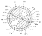
먼저, 도 1 내지 도 3에서는 본 발명에 따른 커플링 기구(1) 예컨대 다단 회동형으로 제공되는 커플링 기구(1)를 도시하고 있다.First, FIGS. 1 to 3 show a
즉, 도 1 내지 도 2에서 도시한 바와 같이, 본 발명의 커플링 기구(1)는, 하나의 축(10)이 조립되는 제1 커플링(20) 및 다른 축(30)이 조립되고 상기 제1 커플링(20)에 수용되는 제2 커플링(40)을 포함하여 구성될 수 있다.That is, as shown in Fig. 1 to 2, the
특히, 본 발명의 커플링 기구(1)는, 도 3 및 다음에 상세하게 설명하는 도 8과 같이, 상기 제1 커플링(20)과 제2 커플링(40)사이에는 회전각 조정을 위한 회전각 조정 공간(S)를 형성한다.In particular, the
즉, 각각의 축(10)(30)과 연결된 제1,2 커플링(20)(40)사이의 회전각 조정 공간(S)으로 인하여, 다음에 상세하게 설명하는 액츄에이터(도 4,5의 110,120 참조)들이 동일한 각도(실제로는 스트로크)로 작동되어도, 상기 제1,2 커플링(20)(40)의 회전 각도는 다르게 조정되고, 따라서 축들의 회전 각도가 다단으로 조정될 수 있는 것이다.That is, due to the rotation angle adjusting space S between the first and
한편, 이와 같은 회전각 조정 공간(S)의 역할(작용)에 대하여는 다음의 도 8에서 다시 상세하게 설명한다.On the other hand, the role (action) of such a rotation angle adjustment space S is demonstrated in detail again in following FIG.
이때, 도 1 내지 도 3에서 도시한 바와 같이, 상기 제1 커플링(20)은 상기 제2 커플링(40)의 수용을 가능하게 하면서 상기 제2 커플링사이에 회전각 조정 공간(S)을 형성토록 제공되는 회전각 조정블록(22)을 포함한다.In this case, as shown in FIGS. 1 to 3, the
예를 들어, 도 1 및 도 3과 같이, 상기 제1 커플링(20)의 회전각 조정블록(22)은 원형 플레이트 형태의 커플링바디(26)의 하부 양측에 수직 중심선을 기준으로 서로 엇갈리는 형태로 일체로 돌출 형성되어 있다.For example, as shown in FIGS. 1 and 3, the rotation
따라서, 상기 커플링 바디에서 돌출된 회전각 조정블록(22)은 그 내측으로 상기 제2 커플링(40)이 수용되는 공간을 제공하고, 따라서 상기 회전각 조정블록(22)의 바디에서 부터의 두께는 상기 제2 커플링(40)의 두께에 대응되는 것이 장치 조립상 바람직할 것이다.Accordingly, the rotation
한편, 상기 회전각 조정블록(22)은 앞에서 설명한 바와 같이, 제2 커플링과의 사이에 상기 회전각 조정공간(S)을 형성하기 위한 제2 커플링 접촉 경사면(22a)(22b)을 형성한다.Meanwhile, as described above, the rotation
따라서, 타원형 플레이트로 형성된 상기 제2 커플링(40)의 양측 수평면(40a)은 상기 접촉 경사면(22a)(22b)들과 회동에 따라 접촉하게 된다. Therefore, both
예컨대, 도 1 및 도 3과 같이, 제2 커플링의 양측 수평면(40a)은 제1 커플링(20)의 양측 회전각 조정블록(22)의 양측 접촉 경사면들중 같은 접촉 경사면(22a)과 접촉하게 된다.For example, as shown in FIGS. 1 and 3, both
따라서, 하나의 축(10)에 의하여 제1 커플링(20)이 회동되거나 또는, 다른 축(30)에 의하여 제2 커플링(40)이 회동되는 어떠한 상태에서도, 상기 제1 커플링의 회전각 조정블록(22)과 제2 커플링(40)사이의 회전각 조정공간(S)에서는 공회전이 발생되면서 구동력 전달이 이루어 지지 않는다. 이 부분 또한 다음의 도 8에서 다시 상세하게 설명한다.Therefore, in any state in which the
한편, 상기 제1 커플링(20)은 일 축의 하단에 구비된 결합홈(12)에 조립되는 결합돌기(24)가 상기 커플링 바디(26)의 상단에 일체로 형성되고, 동시에 상기 제2 커플링(40)의 중심에는 다른 축(30)의 상단에 형성된 결합돌기(32)가 조립되는 결합홈(42)이 형성되어 있다.On the other hand, the
따라서, 도 2와 같이, 상기 일 축(10)이 회전하면 제2 커플링(20)의 회전각 조정블록(22)의 접촉 여부에 따라 제2 커플링(40)에 회전력이 전달되고, 이를 통하여 다른 축(30)의 회전 구동이 수행된다.Therefore, as shown in FIG. 2, when the one
그러나, 본 발명의 경우 지금까지 설명한 회전각 조정블록(22)과 제2 커플링(40)의 접촉 상태에 따라 회전각 조정공간(S) 만큼 회전력이 전달되지 않아 축들의 회전 각도가 조정되는 것이다.However, in the case of the present invention, the rotational angle of the shafts is adjusted as the rotational force is not transmitted as much as the rotational angle adjusting space S according to the contact state of the rotational
이때, 도면에서 상기 결합돌기(24)(32)와 결합홈(12)(42)들을 사각형태로 도시하였지만, 반드시 이에 한정되는 것은 아니고, 원통형상으로 형성시키고, 도시하지 않은 키조립을 통하여 조립 연결할 수 있다.In this case, although the
한편, 도 1 및 도 2와 같이, 상기 제2 커플링이 수용되는 제1 커플링의 외연에는 기구 하우징(50)이 조립될 수 있다.Meanwhile, as shown in FIGS. 1 and 2, the
이와 같은 하우징(50)은, 도 3과 같이 제1 커플링(20)의 회전각 조정블록(22)을 제외한 개방된 부분에서의 제2 커플링 이탈을 방지하는 커버링의 역할을 할 것이다.Such a
따라서, 도 1 및 도3과 같이, 상기 제2 커플링(40)의 양측 수평면사이의 면은 하우징의 내경에 대응하는 직경의 원주면(40b)을 형성하는 것이 바람직하고, 이는 제2 커플링의 회동을 안정적으로 지지되게 할 것이다.Thus, as shown in Figs. 1 and 3, it is preferable that the surface between the two horizontal surfaces of the
그리고, 상기 제1 커플링(20)의 회전각 조정블록(22)의 외연도 제2 커플링과 마찬가지로 하우징(50)의 내경에 대응하는 원주면(22c)으로 형성시키는 것이 필요하다.The outer edge of the rotation
한편, 도 1 및 도 2와 같이, 상기 제 2 커플링(40)이 제1 커플링(20)의 회전각 조정블록(22)사이에 수용되면서 회동될 때, 커플링간 마찰을 줄이기 위하여,상기 제2 커플링(40)의 결함홈(42)에 체결되는 다른 축(30)의 상단 결합돌기(32)에 볼 수용홈(62)을 형성시키고, 볼(60)을 삽입한 상태로, 본 발명의 커플링 기구(1)를 조립하면, 상기 볼(60)은 제2 커플링과 축 상단면과의 제1 커플링(20)의 바디(60) 내면 접촉을 차단하여, 부재간의 마모를 방지시킬 것이다.Meanwhile, as shown in FIGS. 1 and 2, when the
이때, 도 2와 같이, 본 발명의 커플링 기구(1)에서 실제 축(10)(30)과 커플링(20)(40)들은 일단 조립되면 상기 볼(60)의 이탈은 발생되지 않는다.At this time, as shown in FIG. 2, once the
다음, 도 4 내지 도 8에서는 앞에서 설명한 본 발명의 상기 커플링 기구(1)를 포함하는 밸브장치(100)를 도시하고 있다.Next, FIGS. 4 to 8 show a
이때, 액츄에이터와 밸브는 100단위의 도면 부호로 도시하지만, 관련 구동축들은, 앞에서 설명한 커플링 기구의 연계 관계를 쉽게 이해하도록 커플링 기구(1)의 제1,2 커플링과 연계되는 축(10)(30)들과 동일한 도면부호로 나타낸다.In this case, although the actuator and the valve are shown with reference numerals of 100 units, the associated drive shafts are associated with the first and second couplings of the
즉, 도 4 내지 도 5에서 도시한 바와 같이, 본 발명의 커플링 기구(1)는, 상기 본 발명의 커플링 기구(1)와, 상기 커플링 기구를 매개로 동력 전달토록 연결된 제1,2 액츄에이터(110)(120) 및, 상기 제1,2 액츄에이터 중 어느 하나와 연결되어 다단 개폐를 가능토록 구성되고 유체 라인(200)이 연결되는 밸브(130)를 포함하여 구성될 수 있다.That is, as shown in Figs. 4 to 5, the
이때, 도 4와 같이, 상기 커플링 기구(1)의 제1,2 커플링(20)(40)에 상기 제1,2 액츄에이터의 구동축(10)(30)들이 각각 연결되어 있다.In this case, as shown in FIG. 4, the
그리고, 상기 제2 액츄에이터의 구동축(30)은 도 4,5와 같이 상기 밸브(130)에 구비된 개폐구(132)의 샤프트(134)와 연결되어 있다.The
이때, 상기 개폐구(132)는 밸브 하우징 내에서 회동되면서 밸브 시트링(136)과의 접촉 유무에 따라 밸브 하우징에 연결되는 파이프 라인(200)의 개폐를 구현하는 디스크 일 수 있다.In this case, the opening and
따라서, 도 4 및 도 5와 같이, 본 발명의 밸브장치(100)는 2개의 액츄에이터(110)(120)를 연동시키면서도 앞에서 설명한 본 발명 다단 회동형 커플링 기구(1)를 매개로 액츄에이터들의 구동축(10(30)들이 연결되기 때문에, 상기 밸브의 디스크인 개폐구(132)의 회동이 0°-> 90°로 구현되지 않고, 다음의 도 8에서와 같이, 0°-> 45°-> 90°의 2단 개방 또는 90°-> 45°-> 0°의 2단 폐쇄의 다단 회동을 가능하게 한다.Therefore, as shown in Figs. 4 and 5, the
결국, 파이프 라인(200)에 고압수가 흐르는 경우, 본 발명 밸브장치(1)는 밸브 개폐구(132)가 단계적으로 회동되어 폐쇄되기 때문에, 워터 햄머(수 충격) 현상이 발생되지 않게 된다.As a result, when the high pressure water flows through the
예를 들어, 초대형 파이프 라인에서 이와 같은 워터 햄머 현상은 밸브 개폐구(132)와 밸브 시트링(136) 등에 충격을 주면서 이들의 수명을 급속하게 저하시키는 문제가 실제 발생되는 실정이다.For example, such a water hammer phenomenon in a very large pipeline actually causes a problem of rapidly degrading their life while impacting the valve opening and closing
특히, 본 발명의 밸브장치(1)의 경우에는, 매우 간단한 커플링 기구(1)를 사용하기 때문에, 도 4 및 도 5와 같이, 알려진 액츄에이터와 밸브를 사용하면 실제 추가되는 구조가 매우 간단하기 때문에, 실제 설비의 제작이나 설치에 비용 부담이 전혀없다.In particular, in the case of the
한편, 도 6 내지 도 7에서는 본 발명에 따른 액츄에이터(110)(120)들의 도시하고 있다.Meanwhile, FIGS. 6 to 7 illustrate
즉, 본 발명의 밸브장치(1)에서 사용되는 상기 제 1,2 액츄에이터(110)(120)는 에어 공급으로 작동되는 피스톤(P)과 구동축에 연결되는 캠(CA) 및 이들 사이에 연결되는 작동아암(A)을 포함하는 로터리 액츄에이터로 제공될 수 있다.That is, the first and
즉, 액츄에이터 하우징(H)에 상기 피스톤, 캠 및 핀(T)으로 연결되는 작동아암(A)이 내장되고, 커버(CO)가 조립되면, 도 7a 및 도 7b와 같이, 에어 공급 방향에 따라 피스톤(P)은 전진 또는 후진한다.That is, when the operating arm (A) is connected to the actuator housing (H) connected to the piston, cam and pin (T), the cover (CO) is assembled, as shown in Figure 7a and 7b, according to the air supply direction The piston P moves forward or backward.
따라서, 도 7a와 같이, 피스톤(P)의 전진시 연동되는 작동아암(A)에 의하여 핀 연결된 캠(CA)과 일체로 구동축(10)(30)은 시계방향으로 90°회전 구동되고, 반대로 도 7b와 같이, 피스톤(P)이 후진하여 본래 위치로 복귀되면 상기 구동축(10)(30)은 반시계 방향으로 90°회전하게 된다.Therefore, as shown in FIG. 7A, the
즉, 통상 액츄에이터(110)(130)들은, 에어 투입에 따라 피스톤이 미리 설정된 스트로크로 전진 또는 후진하기만 하기 때문에, 작동아암(A)도 전진 또는 후진만 하고, 결국 구동축의 회전도 0° 또는 90°만으로 정해진다.That is, since the
따라서, 구동축(10)(30)의 회전각 조정은 불가능한 것이었다. Therefore, the rotation angle adjustment of the
결국, 본 발명의 커플링 기구(1)를 사용하지 않는 경우, 밸브 개폐구(132)의 회동 각도를 임의로 조정하는 것은 어려웠다. 이는 워터 햄머를 차단하기 어려운 것이다.As a result, when the
이때, 액츄에이터의 구동을 다단으로 하여 작동캠과 구동축(10)(30)의 회전을 다단으로 하기 위하여는, 도 6의 액츄에이터의 하우징(H) 자체의 구조를 변경하여, 2중의 피스톤 구조로 매우 복잡하게 변경하여야 실질적인 작동캠의 다단 회전을 통한 구동축의 다단 회동을 구현할 수 있고, 이경우 액츄에이터 구조 변경에 따른 상당한 제작 비용이 발생되는 것이다.At this time, in order to drive the actuator in multiple stages and rotate the operation cam and the
결국, 본 발명의 밸브장치(1)는 앞에서 설명한 바와 같이, 매우 구조가 간단한 커플링 기구(1)를 이용하기 때문에. 기존에 비하여 설비 제작 비용이 매우 저렴한 것이다.As a result, the
한편, 도 8에서는 본 발명 커플링 기구(1)의 제 1,2 커플링(20)(40)과 제1,2 액츄에이터(110)(120)의 구동축(10)(30)을 각각 연결한 경우, 밸브 개방과 폐쇄사이의 각도 조정(예를 들어 밸브 개폐구(디스크) 회전 각도)의 예를 도시하고 있다.8, the first and
예를 들어, 도 8에서 2개의 제1,2 액츄에이터를 사용하고, 제1 액츄에이터(110)의 구동축(10)은 제1 커플링(20)과 연계되고, 제2 액츄에이터(120)의 구동축(30)은 제2 커플링(40)과 밸브(130)의 개폐구(132)의 샤프트(134)와 연결된 것으로 전제한다.For example, in FIG. 8, two first and second actuators are used, the driving
따라서, 1단계에서, 제1,2 액츄에이터(110)(120)와 밸브(130)의 각도는 각각 0°로 되어 있다.Therefore, in the first step, the angles of the first and
다음, 2단계에서, 도 7a를 참조하면 제1 액츄에이터(110)의 구동축(10)이 앞에서 설명한 바와 같이, 에어 투입에 따라 피스톤(P)의 전진으로 90° 회동하여도 상기 제1 커플링의 회전각 조정블록(22)과 제2 커플링 사이의 공간(S1)에 의하여 제1 커플링의 회전각 조정블록(22)은 수용된 제2 커플링(40)을 45°회전된 다음 밀게 된다.Next, in
따라서, 제2 액츄에이터(120)와 밸브 개폐구(132)는 45°만 회전되고, 이때 반대로 형성되는 제2 커플링 조정블록사이의 공간(S2)으로 인하여 다시 45°만큼 제2 액츄에이터와 밸브 개폐구의 반시계방향의 회동이 구현된다.Accordingly, the
결국, 본 발명의 커플링 기구(1)는, 제1,2 액츄에이터는 정상적으로 작동되나 회전각 조정공간(S)을 형성시키면서 이를 이용하여, 개폐구 즉, 디스크의 회전을 0°-> 45°-> 90°의 다단 개방을 가능하게 하는 것이다..As a result, the
다음, 도 8에서 도시한 바와 같이, 개폐구(134) 즉, 디스크가 개방된 상태에서, 제2 액츄에이터(130)의 작동으로 제2 커플링(40)을 회전시킬 때, 상기 제1 액츄에이터(110)의 피스톤(P)이 작동되지 않도록 에어를 공급하면, 제2 커플링은 공간(S1)으로 회전하다가 45° 지점에서는 에어 주입으로 위치 고정된 회전각 조정블록(22)(ⓕ)에 접촉하여 더 이상 회동되지 않고, 따라서 액츄에이터들을 정상 작동시키어도 제2 액츄에이터의 구동축(30)과 밸브 개폐구는 그 상태를 유지한다. 즉 밸브는 45°만 폐쇄된다.Next, as shown in FIG. 8, when the opening and
다음, 제1 액츄에이터(110)를 작동시키어 시계 방향으로 연계된 구동축(10)과 제1 커플링(20)(의 회전각 조정블록)을 45°더 회전시키면, 최종적으로 밸브 개폐구(디스크)(132)는 밸브 시트링(136)과 접촉하여 파이프 라인(200)을 폐쇄시키는 것이다.Next, by operating the
결국, 도 8과 같이 본 발명 밸브장치(100)는 기존에는 구현하기 어려운 중간 회동 각도(개폐 각도) 예를 들어, 45°의 회동을 가능하게 하기 때문에, 밸브의 다단 개폐를 가능하게 하는 것이다.As a result, as shown in FIG. 8, the
한편, 본 실시예의 밸브장치(100)에서, 상기 회동 각도는 반드시 45°로 한정되는 것이 아님은 물론이다. 예를 들어, 도 3에서 회전각 조정블록(22)의 양측 접촉 경사면(22a)(22b)의 경사각도를 조정하면 제2 커플링(40)의 접촉에 따른 회동 각도를 조정하는 것도 가능한 것이다.On the other hand, in the
다음, 도 9 내지 도 11에서는 본 발명에 따른 다른 실시예의 커플링 기구(1')를 도시하고 있다. 다만. 이하에서는 앞에서 설명한 본 발명 커플링 기구(1)와 동일한구성은 동일 부호로 설명하고, 전체적으로 [']를 붙여서 설명한다.9 to 11 show a
또한, 도 9 내지 도 11의 본 발명의 다른 커플링 기구(1')도 도 4 내지 도 8의 본 발명 밸브장치(100)의 액츄에이터(110)(120)와 연계하여 설치하는 것이 가능함은 물론이다. 예컨대 액츄에이터 구동축이 본 발명 커플링기구의 제1,2 커플링(20')(40')과 연결되는 일축 및 다른축이면 된다.9 to 11, the
다만, 이하에서는 이와 같은 본 발명의 다른 커플링 기구(1')의 밸브 장치 연계 구성은 앞에서 다른 커플링 기구의 연계 구성으로 대체한다.However, in the following, the valve device linkage configuration of the other coupling mechanism 1 'of the present invention is replaced by the linkage configuration of the other coupling mechanism.
한편, 도 9 내지 도 11에서 도시한 바와 같이, 본 발명의 다른 커플링 기구(1')의 제1,2 커플링(20')(40')은 조립시 서로 협력하여 사이에 상기 회전각 조정 공간(S)을 형성시키는 제1,2 조정블록(22')(44')을 포함하여 구성될 수 있다.On the other hand, as shown in Figures 9 to 11, the first and second couplings 20 'and 40' of the other coupling mechanism 1 'of the present invention cooperate with each other during assembly and the rotation angle therebetween. It may be configured to include the first and second adjustment blocks 22 'and 44' to form the adjustment space (S).
따라서, 본 발명의 다른 커플링 기구(1')의 제1,2 조정블록(22')(44')은 원형 플레이트 형태의 커플링바디(26')(46')에 양측으로 서로 대향하여 일체로 돌출 형성된 제1,2 조정블록(22')(44')을 포함한다.Accordingly, the first and second adjustment blocks 22 'and 44' of the other coupling mechanism 1 'of the present invention oppose each other on both sides to the coupling bodies 26' and 46 'in the form of a circular plate. First and second adjustment blocks 22 'and 44' integrally formed.
결국, 본 발명의 다른 커플링 기구(1')는 앞에서 설명한 커플링 기구(1)와는 다르게 제1,2 커플링(20')(40')에 모두 일체로 돌출된 제1,2 조정블록들이 서로 엇갈리게 형성되면서, 조정블록 사이에 도 11과 같이, 회전각 조정공간(S)이 형성되는 것이다.As a result, the other coupling mechanism 1 'of the present invention, unlike the
이때, 상기 커플링 기구(1')의 제1,2 조정블록(22')(44')의 양측면에는 서로 접촉하는 것에 따라 회전각 조정공간(S)의 위치를 변하게 하는 접촉 경사면(22'a) (22'b)(24'a)(24'b)들이 형성되어 있다.At this time, both sides of the first and second adjustment blocks 22 'and 44' of the coupling mechanism 1 'are in contact with each other so that the contact inclined surface 22' changes the position of the rotation angle adjusting space S. a) (22'b) 24'a and 24'b are formed.
즉, 상기 조정블록은 경사면의 각도는 다르지만 전체적으로 평면상으로 볼때 삼각형태로 형성된다.That is, the adjustment block is formed in a triangular shape when viewed in plan view, although the angle of the inclined surface is different.
이때, 앞에서 설명드린 바와 같이, 상기 제1,2 조정블록(22')(44')의 접촉 경사면들의 각도를 조정하면, 회전 각도를 조정할 수 있을 것이다.At this time, as described above, by adjusting the angle of the contact inclined surfaces of the first and second adjustment blocks 22 'and 44', the rotation angle may be adjusted.
따라서, 상기 접촉 경사면들의 접촉에 따라 제1 커플링(20')과 제2 커플링(40')의 제1,2 조정블록들 사이에는 회전각 조정공간(S)이 형성되는 것이다.Therefore, the rotation angle adjusting space S is formed between the first and second adjusting blocks of the first coupling 20 'and the second coupling 40' according to the contact of the contact inclined surfaces.
이때, 상기 제1 커플링(20')의 바디(26') 상부 중앙에는, 상기 일축(10)의 결합홈(12)에 조립되는 돌기(24)가 구비되고, 상기 제2 커플링(40')의 중앙에는 상기 다른축(30)의 결합돌기(32)가 삽입 조립되는 결합홈(42)이 형성되어 있다.In this case, a
따라서, 다른 축(30) 또는 일축(10)의 구동력은 서로 연결되되, 회전각 조정블록(22')(46') 들에 의하여 액츄에이터의 정상 가동시에도 도 8에서 설명한 바와 같이 회전각을 조정하면서 일축과 다른축에 전달되는 것이다.Accordingly, the driving force of the
이와 같은 본 발명의 다른 커플링 기구(1')에서는, 제1,2 커플링(20')(40')에 제1,2 회전각 조정블록(22')(44')들이 바디(26')(46')에서 일체로 돌출 형성되는 구조이므로, 앞에서 설명한 커플링 기구(1)에 비하여 조립 구조는 더 견고할 수 있을 것이다.In the other coupling mechanism 1 'of the present invention, the first and second rotation angle adjusting blocks 22' and 44 'are connected to the first and second couplings 20' and 40 '. Since the structure is formed integrally protruding from the '46', the assembly structure may be more robust than the
그리고, 도 10에서와 같이, 제1,2 커플링의 외연에는 조립후 커플링의 회전 각 조정블록들이 이탈되지 않게 하는 앞에서 설명한 커플링기구의 하우징 보다는 높이가 길게 된 하우징(50)이 조립될 수 있다.And, as shown in Figure 10, the outer periphery of the first and second couplings are assembled with a
한편, 본 실시예의 커플링 기구(1')도 앞에서 설명한 바와 같이, 상기 회동 각도가 반드 시 0°->45°-> 90°로 한정되는 것이 아님은 당연하다, 예를 들어, 도 11에서 제1,2 회전각 조정블록(22')(44')들의 양측 접촉 경사면(22'a) (22'b)(44'a)(44'b)들의 경사각도를 조정하면 조정블록들간의 접촉에 따라 회동 각도는 쉽게 조정 가능한 것이다.On the other hand, as described above, the coupling mechanism 1 'of the present embodiment is also obvious that the rotation angle is not necessarily limited to 0 °-> 45 °-> 90 °, for example, in FIG. Adjusting the inclination angles of both side contact inclined surfaces 22'a, 22'b, 44'a and 44'b of the first and second rotation angle adjustment blocks 22 'and 44' Depending on the contact, the angle of rotation is easily adjustable.
이때, 도 11과 같이, 상기 제1,2 조정블록(22')(44')들의 외측면(22'c) (44'c)은 하우징 조립후 회전을 원활토록 원형으로 형성된다.At this time, as shown in Figure 11, the outer surface 22'c (44'c) of the first and second adjustment blocks 22 ', 44' is formed in a circular shape so as to smoothly rotate after assembly of the housing.
이에 따라서, 지금까지 설명한 본 발명의 커플링 기구(1)와 밸브 장치(100)는 다단의 밸브 개폐를 가능하게 하기 때문에, 밸브는 물론, 라인 수명도 연장시키고, 특히 간단한 커플링 구조를 개선하는 것이므로 설치 공간이 간단하여 기존 액츄에이터의 크기가 확대되지 않아, 설비 제작,설치 및 운영 면에서 매우 실용적인 이점을 제공할 것이다.Accordingly, since the
다음, 도 12 내지 도 13에서는 앞에서 도 4 및 도 5에서 설명한 본 발명 밸브 장치(100)의 다른 형태를 도시하고 있다.Next, FIGS. 12 to 13 show another embodiment of the
즉, 도 12 및 도 13에서는 지금까지 설명한 커플링기구(도 1 내지 도 3의 커플링 기구(1) 또는 도 9 내지 도 11에서 도시한 커플링기구(1'))들을 도 4 및 도 5와는 다르게, 제1 액츄에이터 또는 제2 액츄에이터를 밸브(130)에 직결하고, 이들 제 1 액츄에이터 또는 제2 액츄에이터와 밸브 사이에 상기 커플링기구(1 또는 1')를 연결한 다른 형태의 본 발명 밸브장치를 도시하고 있다.That is, in FIGS. 12 and 13, the coupling mechanisms (
이경우, 앞에서 설명한 밸브장치(100)와 커플링 기구의 연결 배치에서만 다를뿐, 커플링 기구의 기본 작동과 제1,2 액츄에이터(110)(120)의 구동력을 밸브에 다단으로 전달하여 밸브(130)의 다단 개폐를 구현하는 것에는 차이가 없다.In this case, only the arrangement of the
다만, 도 12,13 모두 제 1,2 액츄에이터 사이에 밸브를 연계시키되, 도 12에서는 커플링 기구를 제1 액츄에이터(110)와 밸브(130)사이로 상측에 배치한 것이고, 도 13에는 밸브(130)와 제2 엑츄에이터(120)사이로 하측에 배치한 차이만 있다.In FIGS. 12 and 13, the valve is connected between the first and second actuators. In FIG. 12, the coupling mechanism is disposed between the
예를 들어, 도 4 내지 도 8에서 도시한 바와 같이, 도 12 및 도 13에서도, 커플링 기구의 제1,2 커플링(20,40 또는 20,40')과 제1 또는 제2 액츄에이터 구동축(10)(30)과 밸브 구동축(134)에 연결되고, 밸브의 반대쪽 구동축에는 재1 또는 제 2 액츄에이터의 구동축이 직결된다.For example, as shown in Figs. 4 to 8, also in Figs. 12 and 13, the first and
따라서, 커플링 기구와 연결된 제1 또는 제2 액츄에이터 중 하나는 커플링 기구를 매개로 밸브 개폐구(132)에 연결된 밸브 구동축(134)과 연결되어 있어 상기 커플링 기구에 의하여 도 8과 같이 밸브 개폐구의 45°회동을 가능하게 한다.Therefore, one of the first or second actuator connected to the coupling mechanism is connected to the
동시에, 밸브 반대쪽의 커플링 기구가 연결되지 않고 밸브 구동축과 직결된 제1 또는 제2 액츄에이터가 작동하면 밸브 구동축은 액츄에이터의 설정된 회동각도 즉, 90°로 회동 된다.At the same time, when the coupling mechanism opposite to the valve is not connected and the first or second actuator directly connected to the valve drive shaft is operated, the valve drive shaft is rotated at the set rotational angle of the actuator, that is, 90 °.
물론, 이과정에서 도 8과 같이 커플링기구의 제1,2 커플링 사이에 형성되는 회전각 조정 공간(S)을 형성하는 제 1,2 커플링에 의해서 밸브의 다단 개폐가 가능하게 되는 것이다.Of course, the multi-stage opening and closing of the valve is possible in this process by the first and second couplings forming the rotation angle adjusting space S formed between the first and second couplings of the coupling mechanism. .
이때, 도 12,13의 경우 밸브는 구동축(134)이 도 4,5와는 다르게 상,하측으로 돌출되는 형태가 되어야 함은 물론이다.At this time, in the case of FIGS. 12 and 13, the valve should be shaped such that the driving
본 발명은 지금까지 특정한 실시 예에 관련하여 도시하고 설명하였지만, 이하의 특허청구범위에 의해 마련되는 본 발명의 정신이나 분야를 벗어나지 않는 한도내에서 본 발명이 다양하게 개조 및 변화될 수 있다는 것을 당 업계에서 통상의 지식을 가진자는 용이하게 알 수 있음을 밝혀두고자 한다.While the invention has been shown and described in connection with specific embodiments so far, it will be appreciated that the invention can be modified and modified in various ways without departing from the spirit or scope of the invention as set forth in the claims below. It will be appreciated that those skilled in the art can easily know.
도 1은 본 발명에 따른 커플링 기구를 도시한 분해 사시도1 is an exploded perspective view showing a coupling mechanism according to the present invention;
도 2는 도 1의 조립 상태도Figure 2 is an assembled state of Figure 1
도 3은 도 2의 평면 구성도3 is a plan view of FIG.
도 4는 본 발명에 따른 커플링 기구를 포함하는 밸브 장치를 도시한 정면도4 is a front view showing a valve device including a coupling mechanism according to the present invention.
도 5는 도 4의 측면도5 is a side view of FIG. 4
도 6은 본 발명 밸브장치에서 사용되는 액츄에이터를 도시한 분해 사시도Figure 6 is an exploded perspective view showing an actuator used in the valve device of the present invention
도 7a 및 도 7b는 도 6의 액츄에이터 작동상태를 도시한 개략도7A and 7B are schematic views showing the actuator operating state of FIG. 6
도 8은 본 발명 커플링 기구를 이용하는 경우, 제1,2 액츄에이터에 의한 밸브의 다단 개폐를 나타낸 작동 상태표8 is an operating state table showing the multi-stage opening and closing of the valve by the first and second actuators when using the present invention coupling mechanism.
도 9는 본 발명의 다른 실시예의 커플링 기구를 도시한 분해도9 is an exploded view showing a coupling mechanism of another embodiment of the present invention.
도 10은 도 9의 정면도10 is a front view of FIG. 9
도 11은 다른 실시예의 본 발명 커플링 기구의 제1,2 커플링 결합 상태도11 is a first and second coupling engagement state diagram of the coupling mechanism of the present invention in another embodiment.
도 12 및 도 13은 다른 형태들의 본 발명 밸브장치를 각각 도시한 정면 및 측면 구성도12 and 13 are front and side configuration views showing the valve apparatus of the present invention in different forms, respectively.
* 도면의 주요 부분에 대한 부호의 설명 *Explanation of symbols on the main parts of the drawings
1.... 커플링 기구 10,30....축(구동축)1 ....
20,20'40,40'.... 커플링 22,22'.... 회전각 조정블록20,20'40,40 '....
24,32.... 결합돌기 12,42.... 결합홈24,32 .... engaging
26.... 제1 커플링 바디 40,40'.... 제2 커플링26 ....
44'a,44'b.... 회전각 조정블록 50.... 하우징44'a, 44'b .... Angle of
100.... 밸브장치 110,120....액츄에이터100 .... Valve device 110,120 .... actuator
130.... 밸브 134.... 개폐구130 ....
200.... 파이프 라인 S.... 회전각 조정 공간200 .... pipeline S .... rotation angle adjustment space
Claims (12)
Priority Applications (1)
| Application Number | Priority Date | Filing Date | Title |
|---|---|---|---|
| KR1020090066375A KR101057380B1 (en) | 2009-07-21 | 2009-07-21 | Valve device including coupling mechanism |
Applications Claiming Priority (1)
| Application Number | Priority Date | Filing Date | Title |
|---|---|---|---|
| KR1020090066375A KR101057380B1 (en) | 2009-07-21 | 2009-07-21 | Valve device including coupling mechanism |
Publications (2)
| Publication Number | Publication Date |
|---|---|
| KR20110008839A true KR20110008839A (en) | 2011-01-27 |
| KR101057380B1 KR101057380B1 (en) | 2011-08-18 |
Family
ID=43614787
Family Applications (1)
| Application Number | Title | Priority Date | Filing Date |
|---|---|---|---|
| KR1020090066375A KR101057380B1 (en) | 2009-07-21 | 2009-07-21 | Valve device including coupling mechanism |
Country Status (1)
| Country | Link |
|---|---|
| KR (1) | KR101057380B1 (en) |
Cited By (1)
| Publication number | Priority date | Publication date | Assignee | Title |
|---|---|---|---|---|
| WO2024040452A1 (en) * | 2022-08-24 | 2024-02-29 | Honeywell International Inc. | Actuator with inbuilt automatic synchronization of feedback potentiometer and manually adjustable auxiliary switch switchpoint |
Families Citing this family (1)
| Publication number | Priority date | Publication date | Assignee | Title |
|---|---|---|---|---|
| KR102014654B1 (en) * | 2018-06-07 | 2019-08-26 | 주식회사 유니락 | Valve shutter |
Family Cites Families (1)
| Publication number | Priority date | Publication date | Assignee | Title |
|---|---|---|---|---|
| US6651687B2 (en) * | 2002-02-08 | 2003-11-25 | Taylor Innovations, L.L.C. | Pressure relief system with clutch activated valve |
-
2009
- 2009-07-21 KR KR1020090066375A patent/KR101057380B1/en active IP Right Grant
Cited By (1)
| Publication number | Priority date | Publication date | Assignee | Title |
|---|---|---|---|---|
| WO2024040452A1 (en) * | 2022-08-24 | 2024-02-29 | Honeywell International Inc. | Actuator with inbuilt automatic synchronization of feedback potentiometer and manually adjustable auxiliary switch switchpoint |
Also Published As
| Publication number | Publication date |
|---|---|
| KR101057380B1 (en) | 2011-08-18 |
Similar Documents
| Publication | Publication Date | Title |
|---|---|---|
| US10415711B2 (en) | Mechanical energized sealing ball valve with a single item | |
| JP6774931B2 (en) | Actuator with dual drive | |
| CN110185812B (en) | Ball valve | |
| WO2013129140A1 (en) | Lever type switching valve | |
| JP2017125567A (en) | Repair valve | |
| CA2994417C (en) | Axial-seal butterfly valves | |
| KR101057380B1 (en) | Valve device including coupling mechanism | |
| US10920893B2 (en) | Cage reset planetary roller screw device | |
| CN102808972A (en) | Multi-eccentric three-way half ball valve | |
| CN212899790U (en) | Axial-flow type cut-off valve | |
| WO2012026075A1 (en) | Directional control valve device | |
| US11536379B2 (en) | Ball valve and valve operating method | |
| CN114294438B (en) | Petroleum mechanical valve with emergency blocking function | |
| CN111059315B (en) | All-welded forged steel ball valve | |
| KR101770338B1 (en) | Butterfly valve with the function of check | |
| KR101006896B1 (en) | Rotary Type Actuator | |
| KR101127896B1 (en) | Ball valve for waterworks | |
| JP6638139B2 (en) | Non-sliding valve | |
| JP2001050401A (en) | Valve device | |
| US20230383852A1 (en) | Ball valve assembly | |
| NO175752B (en) | Ball valve | |
| CN202140618U (en) | Multi-eccentric threeway semispherical valve | |
| CN117515211A (en) | Locking correction shifting block forced sealing ball valve | |
| KR101116813B1 (en) | Actuator for driving rotary valve | |
| CN104742075A (en) | Pneumatic air wrench air inlet regulating structure |
Legal Events
| Date | Code | Title | Description |
|---|---|---|---|
| A201 | Request for examination | ||
| E902 | Notification of reason for refusal | ||
| E902 | Notification of reason for refusal | ||
| E701 | Decision to grant or registration of patent right | ||
| GRNT | Written decision to grant | ||
| FPAY | Annual fee payment |
Payment date: 20140521 Year of fee payment: 4 |
|
| FPAY | Annual fee payment |
Payment date: 20150721 Year of fee payment: 5 |
|
| FPAY | Annual fee payment |
Payment date: 20160720 Year of fee payment: 6 |
|
| FPAY | Annual fee payment |
Payment date: 20170626 Year of fee payment: 7 |
|
| FPAY | Annual fee payment |
Payment date: 20181212 Year of fee payment: 9 |
|
| FPAY | Annual fee payment |
Payment date: 20200110 Year of fee payment: 10 |