KR20100123715A - Moulded connection between cannula and delivery part - Google Patents
Moulded connection between cannula and delivery part Download PDFInfo
- Publication number
- KR20100123715A KR20100123715A KR1020107020062A KR20107020062A KR20100123715A KR 20100123715 A KR20100123715 A KR 20100123715A KR 1020107020062 A KR1020107020062 A KR 1020107020062A KR 20107020062 A KR20107020062 A KR 20107020062A KR 20100123715 A KR20100123715 A KR 20100123715A
- Authority
- KR
- South Korea
- Prior art keywords
- hole
- tube
- cannula
- fluid connection
- needle
- Prior art date
Links
Images


Classifications
-
- A—HUMAN NECESSITIES
- A61—MEDICAL OR VETERINARY SCIENCE; HYGIENE
- A61M—DEVICES FOR INTRODUCING MEDIA INTO, OR ONTO, THE BODY; DEVICES FOR TRANSDUCING BODY MEDIA OR FOR TAKING MEDIA FROM THE BODY; DEVICES FOR PRODUCING OR ENDING SLEEP OR STUPOR
- A61M5/00—Devices for bringing media into the body in a subcutaneous, intra-vascular or intramuscular way; Accessories therefor, e.g. filling or cleaning devices, arm-rests
- A61M5/14—Infusion devices, e.g. infusing by gravity; Blood infusion; Accessories therefor
- A61M5/142—Pressure infusion, e.g. using pumps
- A61M5/14244—Pressure infusion, e.g. using pumps adapted to be carried by the patient, e.g. portable on the body
- A61M5/14248—Pressure infusion, e.g. using pumps adapted to be carried by the patient, e.g. portable on the body of the skin patch type
-
- A—HUMAN NECESSITIES
- A61—MEDICAL OR VETERINARY SCIENCE; HYGIENE
- A61M—DEVICES FOR INTRODUCING MEDIA INTO, OR ONTO, THE BODY; DEVICES FOR TRANSDUCING BODY MEDIA OR FOR TAKING MEDIA FROM THE BODY; DEVICES FOR PRODUCING OR ENDING SLEEP OR STUPOR
- A61M5/00—Devices for bringing media into the body in a subcutaneous, intra-vascular or intramuscular way; Accessories therefor, e.g. filling or cleaning devices, arm-rests
- A61M5/14—Infusion devices, e.g. infusing by gravity; Blood infusion; Accessories therefor
- A61M5/158—Needles for infusions; Accessories therefor, e.g. for inserting infusion needles, or for holding them on the body
-
- A—HUMAN NECESSITIES
- A61—MEDICAL OR VETERINARY SCIENCE; HYGIENE
- A61M—DEVICES FOR INTRODUCING MEDIA INTO, OR ONTO, THE BODY; DEVICES FOR TRANSDUCING BODY MEDIA OR FOR TAKING MEDIA FROM THE BODY; DEVICES FOR PRODUCING OR ENDING SLEEP OR STUPOR
- A61M5/00—Devices for bringing media into the body in a subcutaneous, intra-vascular or intramuscular way; Accessories therefor, e.g. filling or cleaning devices, arm-rests
- A61M5/14—Infusion devices, e.g. infusing by gravity; Blood infusion; Accessories therefor
- A61M5/142—Pressure infusion, e.g. using pumps
- A61M5/14244—Pressure infusion, e.g. using pumps adapted to be carried by the patient, e.g. portable on the body
- A61M5/14248—Pressure infusion, e.g. using pumps adapted to be carried by the patient, e.g. portable on the body of the skin patch type
- A61M2005/14252—Pressure infusion, e.g. using pumps adapted to be carried by the patient, e.g. portable on the body of the skin patch type with needle insertion means
-
- A—HUMAN NECESSITIES
- A61—MEDICAL OR VETERINARY SCIENCE; HYGIENE
- A61M—DEVICES FOR INTRODUCING MEDIA INTO, OR ONTO, THE BODY; DEVICES FOR TRANSDUCING BODY MEDIA OR FOR TAKING MEDIA FROM THE BODY; DEVICES FOR PRODUCING OR ENDING SLEEP OR STUPOR
- A61M5/00—Devices for bringing media into the body in a subcutaneous, intra-vascular or intramuscular way; Accessories therefor, e.g. filling or cleaning devices, arm-rests
- A61M5/14—Infusion devices, e.g. infusing by gravity; Blood infusion; Accessories therefor
- A61M5/158—Needles for infusions; Accessories therefor, e.g. for inserting infusion needles, or for holding them on the body
- A61M2005/1581—Right-angle needle-type devices
-
- A—HUMAN NECESSITIES
- A61—MEDICAL OR VETERINARY SCIENCE; HYGIENE
- A61M—DEVICES FOR INTRODUCING MEDIA INTO, OR ONTO, THE BODY; DEVICES FOR TRANSDUCING BODY MEDIA OR FOR TAKING MEDIA FROM THE BODY; DEVICES FOR PRODUCING OR ENDING SLEEP OR STUPOR
- A61M5/00—Devices for bringing media into the body in a subcutaneous, intra-vascular or intramuscular way; Accessories therefor, e.g. filling or cleaning devices, arm-rests
- A61M5/14—Infusion devices, e.g. infusing by gravity; Blood infusion; Accessories therefor
- A61M5/158—Needles for infusions; Accessories therefor, e.g. for inserting infusion needles, or for holding them on the body
- A61M2005/1585—Needle inserters
-
- A—HUMAN NECESSITIES
- A61—MEDICAL OR VETERINARY SCIENCE; HYGIENE
- A61M—DEVICES FOR INTRODUCING MEDIA INTO, OR ONTO, THE BODY; DEVICES FOR TRANSDUCING BODY MEDIA OR FOR TAKING MEDIA FROM THE BODY; DEVICES FOR PRODUCING OR ENDING SLEEP OR STUPOR
- A61M5/00—Devices for bringing media into the body in a subcutaneous, intra-vascular or intramuscular way; Accessories therefor, e.g. filling or cleaning devices, arm-rests
- A61M5/14—Infusion devices, e.g. infusing by gravity; Blood infusion; Accessories therefor
- A61M5/158—Needles for infusions; Accessories therefor, e.g. for inserting infusion needles, or for holding them on the body
- A61M2005/1587—Needles for infusions; Accessories therefor, e.g. for inserting infusion needles, or for holding them on the body suitable for being connected to an infusion line after insertion into a patient
-
- A—HUMAN NECESSITIES
- A61—MEDICAL OR VETERINARY SCIENCE; HYGIENE
- A61M—DEVICES FOR INTRODUCING MEDIA INTO, OR ONTO, THE BODY; DEVICES FOR TRANSDUCING BODY MEDIA OR FOR TAKING MEDIA FROM THE BODY; DEVICES FOR PRODUCING OR ENDING SLEEP OR STUPOR
- A61M39/00—Tubes, tube connectors, tube couplings, valves, access sites or the like, specially adapted for medical use
- A61M39/22—Valves or arrangement of valves
- A61M39/26—Valves closing automatically on disconnecting the line and opening on reconnection thereof
- A61M2039/267—Valves closing automatically on disconnecting the line and opening on reconnection thereof having a sealing sleeve around a tubular or solid stem portion of the connector
-
- A—HUMAN NECESSITIES
- A61—MEDICAL OR VETERINARY SCIENCE; HYGIENE
- A61M—DEVICES FOR INTRODUCING MEDIA INTO, OR ONTO, THE BODY; DEVICES FOR TRANSDUCING BODY MEDIA OR FOR TAKING MEDIA FROM THE BODY; DEVICES FOR PRODUCING OR ENDING SLEEP OR STUPOR
- A61M5/00—Devices for bringing media into the body in a subcutaneous, intra-vascular or intramuscular way; Accessories therefor, e.g. filling or cleaning devices, arm-rests
- A61M5/14—Infusion devices, e.g. infusing by gravity; Blood infusion; Accessories therefor
- A61M5/1413—Modular systems comprising interconnecting elements
Abstract
본 발명은 적어도 제1 구멍(13)과 제2 구멍(12), 즉 바꿔말하면 입구와 출구와 및 적어도 부분적으로 피부 아래 또는 경피에 위치되는 캐뉼라(22)를 가지고, 제1 구멍(13)은 저장부(6) 또는 이와 유사한 것에 유체연통되며, 제2 구멍(12)은 별도의 캐뉼라부(7)의 몸체에 있는 구멍에 유체연통되는 유체연결부에 관한 것이다. 유체연결부는 표면 플레이트(1)에 부착되고, 고체재료로 이루어진 튜브(60) 형태인 것을 특징으로 한다. 더욱이, 본 발명은 이러한 유체연결부를 포함하는 베이스부에 관한 것이다.The invention has at least a first hole 13 and a second hole 12, namely an inlet and an outlet and a cannula 22 which is at least partly located under the skin or transdermally. In fluid communication with the reservoir 6 or the like, the second hole 12 relates to a fluid connection in fluid communication with a hole in the body of a separate cannula part 7. The fluid connection portion is attached to the surface plate 1, characterized in that the tube 60 made of a solid material. Moreover, the invention relates to a base comprising such a fluid connection.
Description
본 발명은 예컨대 인슐린과 같은 치료물질의 계속적인 투여를 위해 주입부와 이송부가 고정될 수 있는 베이스부를 포함하는 장치에 관한 것이다. 일반적으로, 이송부는 저장부와 펌프를 포함하고, 주입부는 통과구멍을 갖춘 몸체와 몸체의 하부측면으로부터 돌출된 인접단부를 갖는 적어도 1개의 캐뉼라를 포함한다. 본 발명은 저장부와 캐뉼라부 사이에 형성된 유체연결부를 포함하고, 유체연결부는 일반적으로 베이스 플레이트에 풀릴 수 없게 부착되어 있으며, 고체재료로 이루어진 튜브형태를 갖는다.
The present invention relates to a device comprising a base portion on which an infusion portion and a delivery portion can be fixed for the continuous administration of a therapeutic substance such as, for example, insulin. Generally, the conveying portion includes a reservoir and a pump, and the injecting portion includes at least one cannula having a body with a through hole and an adjacent end projecting from the lower side of the body. The present invention includes a fluid connection formed between the reservoir and the cannula, wherein the fluid connection is generally unremovably attached to the base plate and has a tubular shape of a solid material.
국제공개 WO 2007/071258은 주입부와 유체 이송부를 포함하는 유체를 이송하기 위한 의료장치를 공개했고, 여기에서 유체 이송부와 주입부는 분리되고 재결합될 수 있다. 유체 이송부는 저장부와 이송부의 작동장치에 설치되어 있는 펌프와 하우스의 형태로 된 유체의 이송을 위한 장치를 포함한다. 주입부는 베이스 플레이트, 베이스 플레이트의 인접측면을 지나서 확장되는 캐뉼라에 설치된 통과구멍을 갖춘 몸체를 구비하는 캐뉼라부, 및 예를 들어 설치 패드의 형태로 사용자의 피부에 베이스 플레이트를 고정하기 위한 수단을 포함한다. 이송부와 주입부는 캐뉼라부에서 유체를 저장부로부터 통과구멍으로 인도하는 유체통로를 구비한 연결부를 통해 조립되고, 이송부 및/또는 주입부로부터 연결부의 연결이 끊길 때, 유체통로는 주입부가 접근하는 것을 방지하기 위한 장치를 포함한다. 이러한 국제공개 발명에서 도 20에서 도 24는 연결부가 베이스 플레이트에 풀릴 수 없게 고정되어 형성된 몸체로 구성되고, 격벽(septum)에 의해 접근을 보호하는 내부칸막이를 구비한다. 이송부가 베이스부에 고정될 때, 격벽은 이송부에 속하는 연결바늘에 의해 관통될 수 있다. 구멍은 유체가 연결부의 내부칸막이의 하부로부터 유연한 튜브로 들어가고 캐뉼라부를 통과하는 것을 가능하게 한다. 유연한 튜브는 주입부의 제1 부에 연결되어 있고, 주입부의 제2 부가 제1부에 위치될 때 유체통로가 유연한 튜브로부터 캐뉼라에 형성된다.
International publication WO 2007/071258 discloses a medical device for transferring a fluid comprising an injection section and a fluid delivery section, wherein the fluid delivery section and the injection section can be separated and recombined. The fluid conveying unit includes a device for conveying a fluid in the form of a pump and a house installed in the reservoir and the operating device of the conveying unit. The injection portion comprises a base plate, a cannula portion having a body with a passage hole installed in the cannula extending beyond the adjacent side of the base plate, and means for securing the base plate to the skin of the user, for example in the form of an installation pad. do. The conveying part and the injecting part are assembled through a connecting part having a fluid path leading the fluid from the reservoir to the through-hole in the cannula part, and when the connecting part is disconnected from the conveying part and / or the injecting part, the fluid passage prevents the inlet part from approaching. Device for preventing. 20 to 24 in the international publication of the present invention is composed of a body formed by fixing the connection portion to the base plate unresolved, and has an inner partition to protect access by a septum (septum). When the conveying part is fixed to the base part, the partition wall can be penetrated by a connecting needle belonging to the conveying part. The apertures allow fluid to enter the flexible tube and pass through the cannula from the bottom of the inner partition of the connection. The flexible tube is connected to the first portion of the infusion and a fluid passageway is formed in the cannula from the flexible tube when the second portion of the infusion is positioned in the first portion.
이러한 국제공개 발명에서 설명된 실시예는 매우 복잡하고, 생산하기가 어렵다.
The embodiments described in this international publication are very complex and difficult to produce.
본 발명의 목적은 저장부와 캐뉼라부 사이에 유체연결부를 제공하는 것이고, 여기에서 유체연결부는 베이스부에 부착되며, 고체재료로 이루어진 튜브형태를 갖는다. 유체연결부가 저장부와 캐뉼라부 사이에 위치되는 것은 유체연결부가 저장부나 예를 들어 튜브는 환자의 피부로 돌출된 실제 캐뉼라를 포함하지 않는 것과 같은 캐뉼라부 중 어느 하나의 부분을 형성하지 않는 것을 의미한다. 튜브는 표면 플레이트에 풀릴 수 있거나 풀릴 수 없게 부착된다.
It is an object of the present invention to provide a fluid connection between a reservoir and a cannula, wherein the fluid connection is attached to the base and has the form of a tube of solid material. Positioning the fluid connection between the reservoir and the cannula means that the fluid connection does not form part of any one of the reservoir or the cannula such as, for example, the tube does not contain the actual cannula protruding into the patient's skin. do. The tube may or may not be attached to the surface plate.
본 발명의 실시예에 따르면, 유체연결부는 고정부에 의해 표면 플레이트에 고정된다. 고정부는 예를 들어 주조에 의해 1개의 부품으로 만들어지거나, 예를 들어 개별적으로 제조된 후에 개별적으로 형성된 부품이 고정부에 조립되는 것과 같이 여러 개의 부품으로 결합 될 수 있다.
According to an embodiment of the invention, the fluid connection is fixed to the surface plate by the fixing part. The fixing part may be made of one part, for example by casting, or it may be combined into several parts, for example after being manufactured separately, the individually formed parts are assembled to the fixing part.
본 발명의 실시예에 따르면, 튜브는 금속 또는 플라스틱으로 이루어지고, 예를 들어 튜브는 스틸로 이루어진 공동의 바늘을 포함할 수 있다.
According to an embodiment of the invention, the tube is made of metal or plastic, for example the tube may comprise a hollow needle made of steel.
본 발명의 실시예에 따르면, 튜브는 1㎜보다 작은 직경을 갖거나, 1㎜보다 작은 최대 단면을 갖는다.
According to an embodiment of the invention, the tube has a diameter smaller than 1 mm or a maximum cross section smaller than 1 mm.
본 발명의 실시예에 따르면, 튜브는 고정부로부터 돌출된 적어도 1개의 날카로운 단부를 구비한다. 단부가 "날카롭다(pointy)"는 것은 단부가 날카로운 엣지를 구비하고, 예를 들어 단부가 보호막을 관통할 수 있다는 것을 의미한다. 튜브의 이러한 실시예는 뭉툭한 단부를 구비할 수 있다. 단부가 "뭉툭하다(blunt)"는 것은 단부가 날카로운 엣지를 구비하지 않는다는 것을 의미한다. 더욱이 본 발명의 실시예에 따르면, 튜브의 날카로운 단부는 연결부의 입구에 있는 연결바늘을 형성할 수 있고, 저장부를 입구쪽으로 밀 때, 연결바늘이 연결부의 제1 구멍을 완벽하게 감싸는 막을 관통한다.
According to an embodiment of the invention, the tube has at least one sharp end projecting from the fixing part. "Pointy" the end means that the end has a sharp edge, for example the end can pass through the protective film. This embodiment of the tube may have a blunt end. "Blunt" the end means that the end does not have a sharp edge. Furthermore, according to an embodiment of the present invention, the sharp end of the tube may form a connecting needle at the inlet of the connecting part, and when the reservoir is pushed toward the inlet, the connecting needle penetrates the membrane which completely surrounds the first hole of the connecting part.
본 발명의 실시예에 따르면, 튜브는 1개의 재료 부품으로 이루어지고, 즉 바꿔말하면 튜브는 여러개의 부품으로 조립되지않지만, 압출성형(extrusion)으로 만들어지거나, 주조로 이루어진다.
According to an embodiment of the invention, the tube consists of one material part, that is to say that the tube is not assembled from several parts, but is made of extrusion or cast.
본 발명의 실시예에 따르면, 튜브는 적어도 1곳에서 0°보다 큰 각도로 구부러진다. 이러한 실시예에 따르면, 튜브는 적어도 2곳에서 0°보다 큰 각도로 구부러질 수 있다. 일반적으로, 각도는 45도보다 크고, 본 발명의 실시예에 따르면 각도는 대략 90°이다. 더욱이, 2곳에서의 각도는 일반적으로 동일할 것이다.
According to an embodiment of the invention, the tube is bent at an angle greater than 0 ° at at least one place. According to this embodiment, the tube can be bent at an angle greater than 0 ° in at least two places. In general, the angle is greater than 45 degrees, and according to an embodiment of the invention the angle is approximately 90 degrees. Moreover, the angles at the two locations will generally be the same.
본 발명의 실시예에 따르면, 튜브가 표면 플레이트에 부착된 후에 튜브는 표면 플레이트와의 관계에서 정지하게 된다.
According to an embodiment of the invention, the tube stops in relation to the surface plate after the tube is attached to the surface plate.
본 발명의 실시예에 따르면, 표면 플레이트의 접촉표면은 신용카드처럼 동일한 크기를 갖고, 즉 바꿔말하면 접촉표면이 유사한 면적을 포함하고, 연결부에 의해 형성된 유체통로의 길이는 최대 3㎝가 된다.
According to an embodiment of the invention, the contact surface of the surface plate has the same size as a credit card, that is to say that the contact surface has a similar area, and the length of the fluid passage formed by the connecting portion is up to 3 cm.
본 발명은 저장부와 캐뉼라부 사이에 형성된 유체연결부를 포함하고, 유체연결부는 일반적으로 베이스 플레이트에 풀릴 수 없게 부착되어 있으며, 고체재료로 이루어진 튜브형태를 갖는다.
The present invention includes a fluid connection formed between the reservoir and the cannula, wherein the fluid connection is generally unremovably attached to the base plate and has a tubular shape of a solid material.
본 발명의 실시예가 첨부된 도면을 참조하여 설명될 것이다.
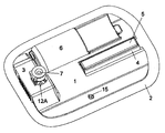
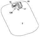
도 1은 이송부가 막을 통과하여 제1 구멍에 연결되고, 캐뉼라부가 제2 구멍에 연결될 수 있는 베이스부의 제1 실시예를 위에서 바라본 상태를 나타낸다.
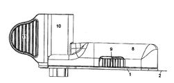
도 2a는 이송부와 주입기가 결합 된 도 1의 실시예를 나타낸다.
도 2b는 주입기가 위치되어 있는 단부에서 바라본 도 2a와 동일한 실시예를 나타낸다.
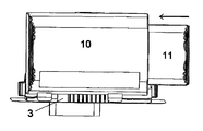
도 3은 삽입되기 전에 이송부와 캐뉼라부가 결합 된 도 1의 실시예를 나타낸다.
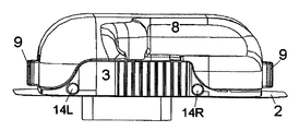
도 4는 연결부가 위치되어 있는 단부에서 바라본 도3의 실시예를 나타낸다.
도 5a는 외부덮개를 연결부에 제공하는 표면 플레이트를 구비한 베이스부의 실시예를 나타내다.
도 5b는 외부덮개가 제거되어 있는 도 5a에서의 베이스부와 동일한 실시예를 나타낸다.
도 6은 외부덮개가 제거되어 있고, 또한 저장부로부터 입구를 감싸는 막이 제거되어 있는 베이스부의 실시예를 나타낸다.
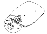
도 7은 베이스부가 2개의 길이방향의 안내수단을 구비하는 본 발명의 제2 실시예를 나타낸다.
도 8은 캐뉼라부의 제1 실시예를 나타낸다.
도 9는 캐뉼라의 제2 실시예를 나타낸다.
도 10a, 10b 및 10c는 내부부품을 포함하는 본 발명에 따른 연결부의 실시예를 나타낸다. 도 10d는 본 발명에 따른 연결부의 내부부품의 제2 실시예를 나타낸다.
도 11a에서 도 11e는 버블막 형태로 된 밀봉재의 다양한 실시예를 나타낸다.
도 12a와 도 12b는 본 발명에 따른 유체연결부의 내부부품의 제2 실시예를 나타낸다.
도 13a와 도 13b는 본 발명에 따른 유체연결부의 내부부품의 제3 실시예를 나타낸다.
도 14는 본 발명에 따른 유체연결부의 내부부품의 제4 실시예를 나타낸다.Embodiments of the present invention will be described with reference to the accompanying drawings.
1 shows a view from above of a first embodiment of a base part in which the conveying part is connected to the first hole through the membrane and the cannula part is connected to the second hole.
Figure 2a shows the embodiment of Figure 1 coupled to the transfer unit and the injector.
FIG. 2B shows the same embodiment as FIG. 2A seen from the end where the injector is located.
3 shows the embodiment of FIG. 1 in which the transfer part and the cannula part are coupled before being inserted.
4 shows the embodiment of FIG. 3 viewed from the end where the connection is located.
Figure 5a shows an embodiment of a base part with a surface plate for providing the outer cover to the connection.
FIG. 5B shows the same embodiment as the base portion in FIG. 5A with the outer cover removed.
FIG. 6 shows an embodiment of the base portion with the outer cover removed and the membrane surrounding the inlet from the reservoir removed.
Figure 7 shows a second embodiment of the invention in which the base portion comprises two longitudinal guiding means.
8 shows a first embodiment of a cannula part.
9 shows a second embodiment of a cannula.
10A, 10B and 10C show an embodiment of a connection according to the invention comprising internal parts. Figure 10d shows a second embodiment of the inner part of the connecting portion according to the present invention.
11A to 11E illustrate various embodiments of a sealing material in the form of a bubble film.
12A and 12B show a second embodiment of the inner part of the fluid connection portion according to the present invention.
13A and 13B show a third embodiment of an internal part of a fluid connection portion according to the present invention.
Figure 14 shows a fourth embodiment of the inner part of the fluid connection according to the present invention.
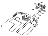
도 1에서 도 6은 본 발명에 따른 베이스부의 제1 실시예를 나타낸다. 이러한 실시예는 접촉표면에 부착된 표면 플레이트(surface plate, 1)를 포함한다. 이러한 실시예에서 표면 플레이트(1)는 주조된 플라스틱 재료로 구성되고, 접촉표면은 설치패드(mounting pad, 2)의 인접측면이 되며, 장치를 제조하는 동안 설치패드(2)가 표면 플레이트(1)에 풀릴 수 없게 고정된다.
1 to 6 show a first embodiment of the base part according to the invention. This embodiment includes a
연결부(connector part, 3)가 표면 플레이트(1)에 부착되거나, 표면 플레이트와 일체로 형성된다. 본 발명의 실시예에 따르면, 장치를 제조하는 동안 표면 플레이트(1)와 연결부(3)의 적어도 1개의 외부덮개가 간단하게 일체로 형성된다. 연결부(3)는 약물의 저장부나 환자로부터 수집된 액체를 위한 저장부와 캐뉼라부(cannula part, 7) 사이에 유체통로를 형성한다. 그리하여, 연결부(3)는 적어도 2개의 구멍을 구비하고, 유체통로(도 5와 도 6에 나타나 있음)의 각 단부에서 제1 구멍(first opening, 13)은 유체를 수용하거나 유체를 저장부(reservoir, 6)로 전달하는 입구 또는 출구가 되고, 제2 구멍(second opening, 12)은 유체를 수용하거나 유체를 캐뉼라부(7)로 전달하는 입구 또는 출구가 된다. 연결부(3)는 예를 들어 제2 약물의 주입이나, 영양분 또는 센서에 연결된 유체통로로 유체를 이끌 수 있는 추가적인 구멍을 구비할 수도 있다. 도 1은 연결부(3)의 제1 구멍(13)에서 연결부(3)에 부착된 저장부(6)를 나타낸다. 이러한 도면에서, 비록 유체통로를 통과하는 유동 방향이 본 발명에서 상당히 중요하지는 않지만, 제1 구멍(13)은 "입구(inlet)"로 언급되고, 제2 구멍(12)은 "출구(outlet)"로 언급될 것이다.
A
캐뉼라부(7)가 연결부(3)에 설치될 때, 연결부(3)는 캐뉼라부(7) 주변에 정확히 밀착되는 캐뉼라 구멍(cannula opening, 12A)을 추가로 구비하고, 즉 바꿔말하면 캐뉼라 구멍(12A)은 캐뉼라부(7)와 같은 동일한 형태를 갖고, 캐뉼라부(7)를 통과하여 구멍에 꼭 들어맞도록 충분히 크기를 갖는다. 도 1에서, 캐뉼라부(7)가 충분히 삽입되어 있지 않은 상태를 나타내고, 일반적으로 삽입단계에서 캐뉼라부(7)가 여전히 주입기의 옆에 위치되고, 주입기는 보이지 않는다. 캐뉼라부(7)가 충분히 삽입될 때, 상부표면, 즉 바꿔말하면 캐뉼라부(7)의 말단표면이 일반적으로 캐뉼라 구멍(12A) 주변의 연결부(3)의 외부표면과 같은 높이에 위치하거나 낮은 높이에 위치한다.
When the
캐뉼라부(7)가 연결부(3)에 완전히 삽입될 때, 캐뉼라부(7)의 몸체(body, 24)의 측면에 있는 구멍(opening, 20)은 연결부(3)의 유체통로의 제2 구멍(12)에 상응하게 되고, 유체가 한쪽 부품으로부터 다른쪽 부품으로 흘러갈 수 있다. 비록 유동방향이 본 발명에서 중요하지 않지만, 캐뉼라부(7)의 몸체(24)에서의 구멍(20)은 앞으로 "입구(inlet)"로써 언급될 것이다.
When the
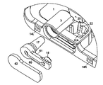
도 2a와 2b는 환자의 피부에 배치되도록 준비된 장치를 나타낸다. 도 2a는 주입기의 측면도를 나타내고, 도 2b는 장치의 주입기의 끝에서 바라본 상태를 나타낸다. 본 발명에 따르면, 장치는 베이스부를 포함하고, 베이스부는 부착력이 있는 인접표면으로 설치패드(2)에 풀릴 수 있게 위치된 표면 플레이트(1)를 구비한다. 베이스부가 이송부(delivery part, 8)에 풀릴 수 있게 연결되어 있고, 주입기(inseter, 10)는 액츄에이터 핸들(actuator handle, 11)을 구비한다. 액츄에이터 핸들(11)은 미리 삽입된 위치에 있다.
2A and 2B show a device ready to be placed on the skin of a patient. 2A shows a side view of the injector, and FIG. 2B shows a view from the end of the injector of the device. According to the invention, the device comprises a base portion, and the base portion has a
이러한 실시예에서의 이송부(8)는 이송부(8)를 안내수단(guiding means, 4)의 아래쪽으로 밀어붙이는 것에 의해서 베이스부에 결합되고, 이러한 경우에 있어서 안내수단은 정상표면에 고정된 금속 라이닝(metal lining, 5)을 구비한 길이방향으로 상승 된 플랫폼이다. 이송부(8)는 안내수단(4) 위에 있는 금속 라이닝(5)의 크기에 일치하는 상응하는 홈(groove)을 구비하고, 여기에서 이송부(8)의 상응하는 홈은 베이스부의 안내수단(4) 위에 있는 금속 라이닝(5)을 따라 길이방향으로 미끄러질 수 있는 방식으로 형성되어 있다. 이송부(8)가 작동위치에 도달할 때, 2개의 풀림핸들(release handle, 9)이 표면 플레이트(1)의 상부표면으로부터 돌출된 2개의 돌출부(protruding part, 15)에 각각 연결된다. 이송부(8)가 작동위치에 있을 때, 풀림핸들(9)에 의해 어떠한 수평방향으로도 잠기게 되고, 금속 라이닝(5)을 구비한 안내수단(4)이 이송부(8)의 상응하는 홈에 위치한다. 이러한 잠김 메커니즘은 베이스부로부터 이송부를 원하는 만큼 자주 고정하거나 풀리게 하는 것을 가능하게 하고, 즉 바꿔말하면 1회용 베이스부가 다수의 이송부에 결합 될 수 있다.
The conveying
주입기(10)가 삽입 전에 캐뉼라부(7)를 붙잡고, 삽입은 액츄에이터 핸들(11)을 미는 것에 의해서 시작된다. 도 2b는 캐뉼라부(7)의 삽입을 시작하기 위해서 액츄에이터 핸들(11)이 밀리는 방향을 나타낸다. 삽입 후에, 도면에 도시되어 있지 않지만, 액츄에이터 핸들이 주입기(10)의 내부로 들어갈 수 있게 되고, 주입기(10)가 베이스부로부터 제거될 수 있으며, 베이스부의 표면 플레이트(1)에 밀착되어 삽입된 캐뉼라(cannula, 22)를 남겨놓게 된다. 만약 캐뉼라부(7)의 캐뉼라(22)가 스스로 관통할 수 있는 단단한 캐뉼라라면, 별도의 삽입바늘이 필요 없게 되고, 따라서 삽입바늘을 들어가게 하는 것이 필요 없게 된다.
The
도 3은 도 2a와 도 2b에 나타난 것과 같은 실시예의 측면도를 나타내지만, 도 3에서는 주입기가 제거되어 있다. 삽입 전에 캐뉼라부가 주입기(10)의 옆쪽에 위치되기 때문에, 캐뉼라부(7)는 동일한 위치를 갖는다.
FIG. 3 shows a side view of the embodiment as shown in FIGS. 2A and 2B, but the injector is removed in FIG. 3. Since the cannula part is located to the side of the
도 4는 도 3과 동일한 실시예를 나타내지만, 도 4는 조립체를 연결부(3)의 끝에서 바라본 상태를 나타내고, 캐뉼라부(7)가 제거되어 있다. 이러한 도면으로부터 주입기(10)의 일부에 상응하는 베이스부의 구멍(opening, 14L, 14R)을 볼 수 있다. 베이스부를 고정하는 수단은 도면에 나타나지는 않았지만 주입기(10) 위에 있는 2개의 돌출부에 상응하는 연결부(3)에서의 2개의 구멍(14L, 14R)을 포함한다. 베이스부에 있는 고정수단(fastening means, 14)이 주입기(10)에 있는 상응하는 고정수단에 결합 될 때, 주입기(10)가 베이스부에 대해 적어도 수직방향 또는 표면 플레이트(1)에 있는 구성부분의 수직방향으로 이동하는 것이 방지된다.
FIG. 4 shows the same embodiment as in FIG. 3, but FIG. 4 shows the assembly as viewed from the end of the connecting
도 5a와 5b는 베이스부의 연결부(3)를 나타낸다. 도 5a에서 연결부(3)가 주조된 표면 플레이트(1)에 의해 형성된 외부덮개를 구비한 상태로 나타나있고, 도 5b는 외부덮개가 없는 상태, 즉 바꿔말하면 설치패드(2)만 있는 상태로 나타나있다. 이러한 실시예에 나타나있는 외부덮개는 별도의 장치가 아니다. 즉 제조과정 동안, 표면 플레이트(1)의 일부에 풀릴 수 없게 부착되거나, 표면 플레이트(1)의 일부로써 간단하게 형성된다. 외부덮개는 캐뉼라부(7)를 위한 캐뉼라 구멍(12A)과 저장부(6)를 위한 제1 구멍(13)을 가지고, 이에 따라 저장부와 캐뉼라부(7)에 의해 연결부(3)의 유체통로의 접근을 허용하게 된다. 캐뉼라 구멍(12A)은 캐뉼라부(7)가 표면 플레이트(1)의 주변에서 환자의 피부 아래 또는 경피(transcutaneous)에 삽입되는 것을 가능하게 하고, 또한 이러한 실시예에서 설치패드(2)에 의해 형성된 베이스부의 접촉표면은 캐뉼라가 삽입되는 것을 가능하게 하는 구멍(opening, 12B)(도 5b에 나타나 있음)을 구비한다. 만약 접촉표면이 적어도 캐뉼라부(7)의 캐뉼라(22)에 의해 관통될 수 있는 재료와 두께로 이루어져 있다면, 이러한 구멍(12B)은 필요 없게 된다.
5a and 5b show the
연결부(3)에서 제2 구멍과(12) 캐뉼라부(7) 사이에 단단한 유체연통되는 것을 보장하기 위해, 연결부(3)의 제2 구멍(12)은 제2 구멍 주변에 탄성 밀봉재(sealing, 18)를 구비한다. 캐뉼라부(7)가 삽입될 때, 캐뉼라 구멍(12A)에 끼워지도록 가압되고, 탄성 밀봉재(18)는 상응하는 구멍(12, 20) 주변에 완벽하게 밀착되는 유체 가스켓(gasket)을 형성한다. 끼워맞춤(pressed-fitting) 및 캐뉼라부(7)와 유체통로의 출구 사이의 밀착되는 유체연결부를 개선하기 위해, 캐뉼라부가 유체통로의 출구가 위치되어 있는 표면에 수직으로 삽입될 때 캐뉼라 구멍(12A)은 캐뉼라에 평행하게 감소하는 단면을 구비할 수 있다. 캐뉼라부(7)는 캐뉼라에 상응하는 감소하는 단면을 갖는다.In order to ensure tight fluid communication between the
연결부(3)에서 제1 구멍(13)과 저장부(6) 사이에 밀착되는 유체연통되는 것을 보장하기 위해, 버블막(bubble membrane, 17)이 제1 구멍(13)에 위치된다. 버블막(17)은 제1 구멍(13)(이러한 실시예에 따르면 연결바늘(connector neddle, 19)의 열린 단부로 이해되는)을 완벽하게 감싸고, 연결부(3)의 오염을 방지한다. 저장부(6)가 연결부(3) 쪽으로 가압될 때, 연결바늘(19)이 버블막(17)을 관통하고 연결부(3)와 저장부(6) 사이에 완벽하게 밀착하는 유체이송을 형성한다.
A
버블막(17)이 버블형태라는 것은 구멍을 감싸는 방식으로 구멍 주변에 부착되는 것을 의미하고, 종종 구멍을 보호하는 구멍의 엣지에 위치되는 것을 의미하며, 버블막(17)은 구멍의 엣지에 의해 형성되는 평면으로부터 돌출되고, 엣지로부터 떨어져서 돔을 형성한다. 돔의 높이나 길이는 연결바늘(19)의 높이에 일치하게 된다.
The bubble shape of the
도 6에서 연결바늘(19)은 연결부(3)의 일부, 즉 바꿔말하면 연결부에 부착된 상태로 나타나 있지만, 연결바늘(19)은 저장부(6)의 일부일 수도 있다.In FIG. 6, the connecting
본 발명의 실시예에 따르면, 연결부(3)는 연결바늘(19)과 버블막(17) 모두를 구비하고, 또한 저장부(6)는 자가 차단막 형태의 버블막을 구비한다. 연결부와 저장부 모두가 버블막을 구비하기 때문에, 서로에 대해 2개의 장치로 분리될 수 있고, 이후에 연결부(3)와 환자에 대한 오염 없이 연결부와 저장부가 재결합될 수 있으다.
According to the embodiment of the present invention, the
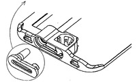
도 7은 베이스부의 제2 실시예를 나타낸다. 이러한 실시예는 베이스부의 표면 플레이트(1)로부터 돌출된 ┓,┏로 형성된 2개의 직각형태의 2개의 안내수단(4)을 구비한다. 안내수단(4)은 베이스부에 고정되는 이송부 또는 덮개 위에 있는 장치에 상응한다. 예를 들어, 이러한 상응하는 수단은 ┛와┗의 형태로 형성된 1개 이상의 후크로 이루어질 수 있다.
7 shows a second embodiment of the base portion. This embodiment comprises two guide means 4 in the form of two right angles formed by ┓, 된 protruding from the
연결부(3)의 유체통로는 도 1~6에 나타난 실시예와 비교하여 아주 짧고, 연결부(3)의 입구는 안내수단(4)과의 관계에서 중앙에 위치되지만, 삽입된 캐뉼라부(7)는 도 1~6의 실시예에서 고정된 캐뉼라부(7)와 동일한 형태를 갖는다.
The fluid passage of the
도 8은 도 1에 나타난 캐뉼라부(7)의 확대도를 나타낸다. 이러한 실시예는 캐뉼라(22) 및 평평한 표면을 갖는 돌출된 앞면(protruding front, 25)을 구비한 몸체(24)를 포함한다. 구멍을 구비한 캐뉼라부(7)의 돌출된 앞면은 평평할 필요가 없다. 즉, 캐뉼라부(7)를 마주 대하는 연결부(3)의 표면에 상응하도록 형성될 수 있다면, 실질적으로 어떠한 형태든 상관없다. 본 발명의 실시예에서, 삽입된 후에 돌출된 앞면(25)은 상부, 즉 바꿔말하면 말단부에서의 단면이 인접단부, 즉 바꿔말하면 환자에 인접한 단부의 단면보다 더 큰 것과 같은 방식으로 기울어져 있다. 돌출된 앞면(25)은 구멍(20)을 구비하고, 액체는 이러한 구멍을 통해서 캐뉼라부(7)로 들어오거나 배출될 수 있다. 몸체(24)는 정상구멍(top opening, 21)을 추가로 구비하고, 이러한 정상구멍은 자가 차단막(self closing membrane)으로 덮일 수 있다. 정상구멍은 주변과 접촉하는 외부표면과 마주하기 때문에, 정상구멍(21)은 입구를 보호하기 위한 수단이 요구된다. 만약 캐뉼라(22)가 부드러운 캐뉼라라면, 정상구멍(21)은 캐뉼라부(7)가 삽입될 때 처음으로 사용된다. 캐뉼라(22)가 부드럽다는 것은 캐뉼라가 환자의 피부를 관통할 수 없는 상당히 부드러운 재료로 이루어졌다는 것을 의미하고, 이러한 경우에 있어서 캐뉼라를 삽입할 때, 상당히 단단한 재료의 날카로운 삽입바늘이 필요하게 되고, 이러한 날카로운 삽입바늘은 정상구멍(21)을 통해 삽입될 수 있고, 캐뉼라부의 몸체(24)에 있는 내부공동을 통해 지나갈 수 있으며, 더욱이 삽입바늘의 날카로운 단부가 캐뉼라(22)의 공동의 구멍단부를 찌르는 방식으로 캐뉼라(22)의 전체 길이를 지나서 통과할 수 있다. 삽입 후에, 즉 바꿔 말하면 캐뉼라(22)가 환자의 피부 아래나 경피에 위치해 있을 때, 삽입바늘이 환자 안으로 들어가게 되고, 캐뉼라(22)가 환자 몸안에 남아있게 된다.
FIG. 8 shows an enlarged view of the
도 9는 캐뉼라부(7)의 제2 실시예에 의한 확대도를 나타낸다. 또한, 이러한 실시예는 캐뉼라(22) 및 구멍(20)을 구비한 평평한 표면을 갖는 돌출된 앞면(25)을 구비한 몸체(24)를 포함하지만, 이러한 실시예에 따르면 돌출된 앞면(25)은 구멍(20)과 연결부(3)의 제2 구멍 주변에 있는 밀봉재(18) 사이에서 압력이 감소하는 방식으로 기울어져 있다. 돌출된 앞면의 기울기는 캐뉼라(22)의 센터라인(c)과 구멍(20) 둘레에 있는 표면에 평행한 선 사이에 있는 각도(d)에 의해 결정된다. 각도(d)는 0°보다 크고 90°보다 작으며, 직경 또는 밀봉재(18)의 돌출에 따라 각도(d)는 일반적으로 0°에서 30°, 또는 60°에서 90°가 된다. 돌출된 앞면(25)의 말단부 사이에서의 길이(d1)(즉 바꿔 말하면 캐뉼라부(7)의 단부)는 삽입 후에 환자로부터 가장 멀리 떨어져 있고, 캐뉼라부(7)의 중심부(c)는 인접단부(즉 바꿔말하면, 삽입 후에 환자와 가까운 단부)에서 돌출된 앞면(25)과 캐뉼라부(7)의 중심부(c) 사이의 길이(d2)보다 더욱 길다. 일반적으로 길이(d2)는 삽입 동안에 돌출된 앞면(25)의 인접단부가 연결부(3)의 밀봉재(18)에 접촉하지 않도록 매우 작게 된다.
9 shows an enlarged view according to the second embodiment of the
도면에 나타나지는 않았지만 실시예에서, 각도(d)는 90°에 가깝고, 즉 각도(d)는 90°이며, 도 9에 상응하는 도면에 있어서 이러한 실시예는 연결부(3)의 제2 구멍(12)이 캐뉼라부(7)의 아래쪽 구멍(20)에 밀착되는 것을 나타낸다. 이는 캐뉼라부(7)를 밀봉재(18) 방향으로 미는 힘이 밀봉재(18)의 접촉표면에 대해 수직에 가깝다는 것을 의미하고, 이는 캐뉼라부(7)의 삽입 동안 밀봉재(18)가 밀봉재(18)을 따라 미끄러지는 캐뉼라부(7)에 의해 비틀리는 것을 방지한다.Although not shown in the figures, in the embodiment, the angle d is close to 90 °, ie the angle d is 90 °, and in the figure corresponding to FIG. 9 this embodiment shows a second opening ( 12) is in close contact with the
본 발명의 다른 실시예(도 8에 나타난)에서, 돌출된 앞면(25)과 중심선(c)이 평행하기 때문에, 각도(d)가 0°이 된다. 이러한 실시예에 따르면, 캐뉼라부(7)는 밀봉재의 비틀림을 발생시킬 수 있는 돌출된 밀봉재(18)에 접촉하여 미끄러진다.
In another embodiment of the present invention (shown in FIG. 8), since the protruding
도 8의 실시예에 따르면, 캐뉼라부(7)의 돌출된 앞면(25)이 평평할 필요가 없다. 즉, 캐뉼라부(7)와 마주하는 연결부(3)에서 상응하는 표면을 형성할 수 있는한, 실질적으로 어떠한 형태든 상관없다. 또한, 돌출된 앞면(25)의 구멍(20)은 캐뉼라부(7)의 목적에 따라 입구나 출구가 될 수 있다. 단면을 볼 수 있는 도 9에서, 몸체(24)의 정상구멍(21)이 자가 차단막(self closing membrane, 21A)으로 어떻게 덮여 있는지를 알 수 있다. 도 8의 실시예에 따르면, 만약 캐뉼라(22)가 부드러운 캐뉼라라면, 캐뉼라부(7)가 삽입될 때, 정상구멍(21)이 최초로 사용되지만, 또한 정상구멍(21)은 환자가 구멍(20)을 통해 받아들이는 인슐린과 같은 초기 약물 이외에 약물이나 영양분을 주입하는 데 사용될 수 있다.
According to the embodiment of FIG. 8, the protruding
또한, 캐뉼라부(7)의 이러한 실시예는 고정수단(fastening means, 23)을 구비하고, 이러한 실시예에서 고정수단(23)은 캐뉼라부(7)에서 돌출부분의 형태를 갖고, 고정수단은 정지한 베이스부 위에 있는 유연부(flexible part, 23A)에 상응한다. 캐뉼라부(7)가 삽입되는 동안에, 캐뉼라부(7)에 있는 고정수단(23)이 통과할 때, 유연부(23A)가 도 9에서 화살표가 가리키는 것처럼 바깥쪽으로 밀릴 수 있다. 삽입 후에, 캐뉼라부(7)의 고정수단(23)에서의 상부표면은 베이스부의 유연부(23A)의 하부표면에 의해 잠기게 되고, 이에 따라 캐뉼라부(7)를 베이스부로부터 분리할 수 없게 된다.
In addition, this embodiment of the
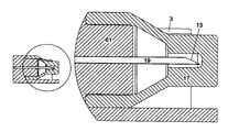
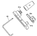
도 10a에서 도 10c는 연결부(3)의 실시예를 나타낸다. 도 10a는 연결부(3)의 실시예의 확대도를 나타내고, 여기에서 유체통로를 제공하는 튜브(tube, 60)를 위한 내부 고정부(holding part, 61)가 나타나있다. 도 10b는 내부 고정부(61)의 투시도를 나타내고, 이러한 도면에 따르면, 튜브(60)의 위치를 알 수 있다. 도 10c는 도 10a의 둘러싸이는 부분의 확대도를 나타낸다.
10a to 10c show an embodiment of the connecting
본 발명의 실시예에 따르면, 연결부(3)와 표면 플레이트(1)는 플라스틱 재료로 일체로 형성되고, 연결부는 다수의 구멍을 구비하며, 1개의 캐뉼라 구멍(12A)이 캐뉼라부(7)에 고정되기 위해 준비되고, 다른 구멍이 연결부(3)의 내부부품(internal part)에 고정되기 위해 준비된다. 본 발명의 실시예에 따른 연결부(3)의 내부부품은 1개의 튜브를 포함하고, 튜브는 2곳에서 90°로 구부러져 있고, 즉 바꿔말하면 튜브(60)의 입구쪽 단부와 출구쪽 단부가 튜브(60)의 연결부에 대해 수직방향과 동일한 방향을 가리키고, 튜브(60)의 연결부는 2개의 구부러진 부분 사이에서 유체통로를 형성한다.
According to an embodiment of the invention, the
한쪽 단부에서 튜브(60)는 버블막(17)으로 보호되고, 다른 쪽 단부에서 튜브(60)는 개방되어 보호되지 않지만, 개방된 튜브의 단부는 고정부(61)에 풀릴 수 없게 부착된 밀봉재(18)에 의해 둘러싸여 있다. 내부부품이 연결부(3)에 상응하는 구멍에 위치될 때, 구멍에 정확하게 밀착되는 덮개(cover, 62)가 사용자가 부드러운 표면을 만지작거리지 않는 한 연결부(3)의 표면에 같은 높이로 위치된다.
At one end the
도 10b는 연결부(3)의 내부부품의 확대도를 나타낸다. 고정부(61)는 튜브(60)에 안정되게 끼워질 수 있도록 일체로 형성된 부분을 포함한다. 튜브(60)의 열려있는 뭉툭한 단부가 밀봉재(18)에 의해 둘러싸인 공간으로 열려 있다. 튜브(60)의 닫혀있는 날카로운 단부는 부드러운 막에 의해 완전히 둘러싸여 있다. 이러한 실시예에서 연결바늘(19)을 구성하는 튜브(60)의 단부는 버블막(17)에 실질적으로 접촉하지 않는다. 연결바늘(19)은 공기에 의해 둘러싸여 있고, 연결바늘(19)을 둘러싸는 내부공간은 원통형태 또는 원뿔형태로서, 즉 원형 단면을 갖는다. 막의 길이가 적용된 압력에 의해 감소 될 때, 버블막(17)의 벽은 안쪽 또는 바깥쪽으로 구부러지는 것에 의해 변형될 것이다.
10B shows an enlarged view of the internal parts of the connecting
도 10c는 도 10a에 도시되어 있는 둘러싸이는 부분의 확대도를 나타낸다.
FIG. 10C shows an enlarged view of the enclosed portion shown in FIG. 10A.
도 10d는 연결부(3)의 제2 실시예에서의 내부부품의 확대도를 나타낸다. 또한, 이러한 실시예에 따르면, 고정부(61)는 튜브(60)의 안정되게 끼워질 수 있도록 일체로 형성된 부분을 포함하지만, 이러한 실시예에서 고정부(61)는 원형태 또는 원통형태이고, 단단하지 않은 밀봉재(18)가 튜브(60)의 뭉툭한 단부에 부착되고, 즉 바꿔말하면 튜브(60)의 열려있는 뭉특한 단부가 밀봉재에 의해 둘러싸인 공간으로 열려 있다. 도 10b에서처럼 날카로운 튜브(60)의 닫혀있는 단부는 버블막(17)에 의해 완전히 둘러싸여 있고, 고정부(61)는 내부부품에 조립된 내부부품을 연결부(3)에 형성된 구멍의 위치로 밀어넣기 위해 충분한 안전성을 제공한다. 모든 실시예에서 "완전히 둘러싸여 있다(completely surrounded)"는 것은 주변에 접근하는 자유단이 없다는 것을 의미하고, "부드러운 막(soft membrane)"이란 막이 바늘에 의해, 특히 튜브(60)의 단부에 설치되고 버블막(17) 안에 꽂혀 있는 연결바늘(19)에 의해 관통될 수 있다는 것을 의미한다.
10D shows an enlarged view of the internal parts in the second embodiment of the connecting
이러한 실시예에 따르면, 연결바늘(19)은 실제로 둘러싸고 있는 버블막(17)에 접촉되지 않는다. 연결바늘(19)은 공기에 의해 둘러싸여 있고, 연결바늘(19)을 둘러싸는 내부공간은 원통형태 또는 원뿔형태로서, 즉 원형 단면을 갖는다. 막의 길이가 가해진 압력에 의해 감소 될 때, 버블막(17)의 벽은 안쪽 또는 바깥쪽으로 구부러지는 것에 의해서 변형될 것이다.
According to this embodiment, the connecting
도 11a는 버블막(17)의 실시예에 대한 확대도를 나타낸다. 이러한 버블막(17)은 연결바늘이 꽂혀있는 고정부(61)의 표면으로부터 돌출된 연결바늘(19)의 일부를 완전히 둘러싼다. 압력이 버블막(17)에 가해지지 않을 때, 즉 바꿔말하면 연결바늘(19)이 연결바늘(19)을 살균할 수 있는 가스인 공기에 의해 완전히 둘러싸여 있을 때, 연결바늘(19)은 버블막(17)에 접촉하지 않는다. 이러한 상태가 도면에 나타나 있다. 연결바늘의 단부가매우 두꺼운 벽을 갖는 막 부분으로 둘러싸여 있고, 반면에 고정부에 인접한 막의 일부는 연결바늘 끝에 있는 벽두께의 대략 절반 두께의 벽을 갖으며, 이에 따라 압력이 막에 가해질 때, 막의 일부가 벽의 두께를 감소시키는 대신에 두꺼운 벽 부분은 형태가 변하지 않게 된다. 즉, 바꿔말하면 고정부에 인접한 부분이 보내지고 고정부(61) 쪽으로 가압 된다.
11A shows an enlarged view of an embodiment of the
도 11b는 버블막(17)의 다른 실시예를 나타낸다. 이러한 실시예에 따르면, 입구 보호막(protecting membrane, 6A)을 구비한 저장부(6)가 연결바늘(19)을 감싸는 막쪽으로 밀리게 된다. 버블막(17)은 연결바늘(19)이 보호막(6A)을 관통할 수 있고 저장부(6)에 접근하는 것을 보장할 수 있도록 길이가 변형될 수 있는 유연한 재료로 이루어진다.
11B shows another embodiment of the
도 11c는 연결부(3)의 구멍을 보호하는 버블막(17)의 다른 실시예를 나타낸다. 이러한 버블막(17)이 버블형태는 아니지만, 벽에 연결바늘(19)을 둘러싸는 공간을 형성한다. 벽은 유연하고, 즉 바꿔말하면 저장부가 벽에 압력을 가할 때, 벽은 뒤로 물러날 수 있다. 버블막(17)은 1개 이상의 스프링에 의해 제자리로 유지되고, 즉 바꿔말하면 원위치를 유지하는 저장부로부터 압력이 방출될 때, 버블막(17)이 원래의 위치로 되돌아 갈 수 있다. 막이 앞뒤로 미끄러질 수 있는 구멍이 저장부(6)의 연결부에 단단하게 밀착된다.
FIG. 11C shows another embodiment of a
도 11d는 저장부의 다른 실시예를 나타내고, 여기에서 보호막(6A)이 저장부(6)의 입구에 설치되어 있으며, 입구가 연결부(3)의 유체통로에 연결되어 있다. 도면에 도시되지는 않았지만, 유체통로가 저장부(6)에 연결되어 있지 않은 기간 동안, 저장부(6)에 연결된 유체통로의 단부는 유체통로의 입구를 보호하기 위한 막을 구비한다. 이러한 실시예에 따르면, 연결바늘(19)이 저장부(6)의 일부이기 때문에, 유체통로는 연결바늘(19)을 구비할 필요가 없다.
FIG. 11D shows another embodiment of the reservoir, where a
도 11e는 버블막(17)의 다른 실시예와 저장부에 보관된 약물에 유체통로를 형성하기 위해 저장부가 연결바늘(19)에 대해 어떻게 밀리는지를 나타낸다. 버블막(17)은 유연하고, 저장부(6)의 입구를 버블막(17)과 연결바늘(19)을 둘러싸는 연결부에 있는 구멍에 밀어 넣어지는 것을 가능하게 하는 방식으로 버블막의 사이즈가 감소 될 수 있고, 즉 바꿔말하면 버블막(17)의 길이는 버블막(17)의 직경이 늘어날 필요없이 감소 될 수 있다. 도시된 실시예에 따르면, 버블막의 재질이 안쪽으로 접힌다.
FIG. 11E shows another embodiment of the
도 12a와 도 12b는 유체를 저장부(6)로부터 캐뉼라부(7)로 전달할 때, 밀착되는 유체연결부를 제공하는 선택적인 실시예를 나타낸다. 도 12a와 도 12b 모두에서 연결부(3)의 내부부품은 확대된 형태로 나타나있다.
12A and 12B show an alternative embodiment of providing a tight fluid connection when delivering fluid from
이러한 실시예에 따르면, 연결부(3)의 내부부품은 튜브(60)를 위한 고정부(61), 제2 구멍(12) 둘레에서 밀봉재를 위한 고정수단(fastening means for sealing, 18a), 고정부(61)로부터 분리되고 버블막을 위한 고정수단(fastening means, 61a)의 반대쪽에 밀봉재를 형성하는 부드러운 버블막(17)을 위한 고정수단(61a), 및 연결바늘(19)과 버블막(17)을 포함한다.
According to this embodiment, the internal parts of the
튜브(60)는 스틸이나 단단한 플라스틱 재료와 같은 단단한 파이프 형태의 직선부분 또는 구부러진 부분 중에 하나로 구성될 수 있고, 튜브(60)는 고정부(61)에 의해 고정되고, 이러한 실시예에서 고정부(61)는 도 12a에 나타난 고정부(61)의 외측면에 의해 형성된 덮개표면을 제공한다. 만약 튜브(60)가 재료의 직선부분이라면, 캐뉼라부(7)에 연결된 단부인 튜브(60)의 제2 단부가 고정부(61)로 형성되고 밀봉재를 위한 고정수단(18a)에 있는 작은 구멍(small opening, 18c)을 통과하여 캐뉼라부(7)에 입구/출구를 갖는 공간 안으로 개방된다. 만약 튜브(60)가 재료의 구부러진 부분이라면, 튜브(60)의 제2 단부는 밀봉재를 위한 고정수단(18a)으로 형성된 작은 구멍(18c)을 통과하여 90도의 각도로 구부러진다. 밀봉재를 위한 고정수단(18a)은 밀봉재(18)를 고정부(61)에 고정하기 위한 수단을 제공한다. 밀봉재를 위한 고정수단(18a)은 고정부(61), 밀봉재를 위한 고정수단(18a), 및 분리된 밀봉부(separate sealing part, 61b)가 서로에 대해 압력을 받을 때 튜브(60)와 연결바늘(19) 사이에 연결공간을 형성하는 큰 구멍(large opening, 18b)을 구비한다. 연결공간이 연결바늘(19)로부터 들어온 유체로 가득 채워질 수 있고 이후에 유체가 튜브(60)를 통해 배출될 수 있기 때문에, 연결공간은 연결바늘(19)과 튜브(60) 사이에 유체연결을 형성한다. 밀봉재를 위한 고정수단(18a) 쪽으로 회전되는 버블막을 위한 고정수단(61a)의 측면은 연결공간에 꼭 맞는 유체연결을 유지하기 위해 밀봉재를 구비할 수 있다.
The
도 13a와 도 13b는 도 10a~10c에 나타난 연결부와 비교되는 연결부의 다른 실시예를 나타내고, 여기에서 연결부(3)는 동일한 장치로 구성된다. 도 13b는 연결부(3)의 내부부품이 연결부(3)의 외부부품에 대해 위치되는 상태를 나타낸다. 도 13a는 도 13b에서 내부부품을 둘러싸는 연결부(3)의 내부부품의 확대도를 나타낸다.
Figures 13a and 13b show another embodiment of the connecting section compared to the connecting section shown in Figures 10a-10c, where the connecting
도 10a~10c에서와 동일하게, 고정부(61)는 1개로 형성된 부품이다. 고정부(61)는 튜브에 안정적으로 끼워질 수 있도록 형성되고, 고정부(61)는 일반적으로 일체로 형성되지만, 2개 이상의 작은 부품을 결합하는 것에 의해서 형성될 수도 있다. 이러한 작은 부품은 용접이나 글루딩(gluding)에 의해 결합 될 수 있다. 고정부(61)가 다소 작기 때문에(일반적으로 2㎝ 보다 작다), 작은 부품을 결합시키는 것이 어려울 수 있다.
As in FIGS. 10A to 10C, the fixing
튜브(60)는 2개의 액체가 통과하여 들어오거나 나갈 수 있는 2개의 개방단부(open end)를 구비하고, 튜브(60)가 고정부(61)에 설치될 때, 제1 개방단부는 닫혀있는 버블막(17)에 의해 둘러싸이는 공간으로 열리고, 제2 개방단부는 밀봉재(18)에 의해 둘러싸이는 공간으로 열리게 된다.
The
튜브(60)의 제1 개방단부는 날카롭고, 이러한 튜브(60)의 제1 개방단부가 튜브(60)의 개방단부를 감싸는 폐쇄된 버블막(17)과 저장부(6)의 입구를 보호하는 보호막(6A) 모두를 관통하기 때문에 저장부에 연결을 형성한다. 도 10a~10c에 나타난 실시예에서 처럼, 튜브(60)의 이러한 단부는 버블막(17)에 의해 완전히 둘러싸이고, 여기에서 "완전히 둘러싸인다"는 튜브(60)의 제1 개방단부로부터 주변으로 접근하는 자유단이 없다는 것을 의미하고, "버블막"이란 막이 바늘, 특히 튜브(60)의 단부에 형성된 연결바늘(19)에 의해 관통될 수 있다는 것을 의미한다. 이러한 실시예에서, 버블막(17)이 주변으로부터 영향을 받지 않을 때, 연결바늘(19)을 구성하는 튜브(60)의 단부는 버블막(17)에 접촉하지 않는다. 이러한 실시예에 따르면, 버블막(17)은 상당히 부드럽고 고분고분한 막재료를 고정부(61)에 대해 가압하는 것에 의해 고정부(61)에 고정되고, 고정부(61)에 가장 가깝운 버블막(17)의 엣지가 직경을 확장할 수 있고, 고정부에 형성된 버섯형태를 넘어서 미끄러질 수 있고, 고정부에 형성된 버섯형태는 고정부(61)에 풀릴 수 없는 부분이다. 버블막(17)이 최종위치에 있을 때, 버블막(17)의 확장된 직경은 작은 크기로 되돌아올 수 있고, 직경의 이러한 감소는 버블막(17)을 버블막을 위한 고정수단(61a) 둘레에서 제 위치로 유지한다. 버블막(17)이 버블막을 위한 고정수단(61a)에 기대어 있는 1개 이상의 안쪽으로 돌출된 부분을 구비한다면, 버믈막(17)이 설치된 후에 버블막(17)이 고정부(61)에 가장 가깝게 위치되고, 가장 작은 직경을 갖도록 강화된다.The first open end of the
튜브(60)의 제2 개방단부는 뭉툭하고, 밀봉재(18)의 닫혀있는 범위 안으로 열리며, 즉 바꿔말하면 밀봉재는 짧은 파이프 형태를 갖고, 튜브(60)의 안과 밖에서 흐름을 정지시키지 않는다. 밀봉재(18)는 밀봉재를 위한 고정수단(18a)에 의해 고정부(61)에 고정되고, 밀봉재를 위한 고정수단(18a)은 밀봉재(18)을 고정부(61)에 풀릴 수 없게 용접하거나 아교로 붙이는 것으로 용이하게 하도록 한다.
The second open end of the
튜브(60)는 일체로 형성된다. 일반적으로 스틸 또는 단단한 플라스틱 재료로 만들어진다. 만약 사용하는 동안 버블막(17)을 관통할 수 있도록 튜브의 단부를 날카롭게 형성한다면, 버블막(17)과 저장부(6)의 입구를 감싸는 보호막(6A)을 관통하기에 충분히 단단한 재료로 적어도 만들어져야만 한다. 이러한 실시예에 따르면 저장부(6)가 유체를 캐뉼라부(7)에 전달할 때 버블막(17)을 관통할 수 있는 연결바늘(19)을 구비하기 때문에, 튜브(60)를 2개의 뭉툭한 단부로 형성하는 것이 가능하다.
The
도 13a와 도 13b의 실시예에 따르면, 튜브(60)는 2곳에서 구부러져 있다. 이러한 실시예에 따르면 저장부(6)와 캐뉼라부(7)가 고정부(61)에 대해 같은 방향으로 설치되는 것이 적절하다. 구부러진 2곳 모두의 각도는 90도이고, 만약 튜브가 밀어 넣어지는 것에 의해 고정부(61)에 일체로 위치된다면, 이러한 2개의 구부러진 곳에 의해 형성된 2개의 다리는 2개의 구부러진 곳 사이에 있는 연결튜브에 대해 동일한 각도를 구비해야만 한다. 만약 저장부(6)와 캐뉼라부(7)가 서로에 대해 다른 방향으로 위치된다면, 캐뉼라부(7)가 표면 플레이트(1)의 엣지에 가깝게 위치되고, 캐뉼라부가 튜브(60)의 제1 단부와 오직 구부러진 곳을 향해 꺽여있는 구멍(20)을 구비한 돌출된 앞면을 구비한 상태에서 튜브(60)가 오직 한 번만 구부러질 수 있다.
According to the embodiment of FIGS. 13A and 13B, the
본 발명의 실시예에 따르면, 튜브(60)는 예를 들어 스틸로 만들어진 공동바늘(hollow needel)을 포함한다. 이러한 바늘은 자동공정의 적은 비용으로 쉽게 생산될 수 있다. 또한, 이러한 바늘은 저장부(6)와 캐뉼라부(7) 사이에 위치되는 바늘의 어떠한 요구라도 충족시키기 위해서 1개 이상의 위치에서 쉽게 구부러질 수 있다. 뭉툭하거나 날카로운 단부를 구비한 바늘은 바늘의 단부에 상응하는 부품에 의존할 수 있지만, 일반적으로 바늘은 보호막을 관통할 수 있는 적어도 1개의 날카로운 단부를 구비한다.
According to an embodiment of the invention, the
만약 연결부(3)가 표면 플레이트(1)의 중앙에 위치된다면, 저장부(6)는 튜브(60)의 제1 단부에서 연결부(3)의 한쪽에 위치될 수 있고, 캐뉼라부(7)는 튜브(60)의 제2 단부에서 연결부(3)의 반대쪽에 위치될 수 있으며, 튜브(60)는 어떠한 구부러진 부분도 없이 직선일 수 있다.
If the
본 발명에 따르면, 튜브(60)가 고정부(61)에 위치되고 표면 플레이트(1)에 설치된 후에, 튜브(60)는 표면 플레이트(1)에 대해 정지해 있다. 튜브(60)가 정지해 있다는 것은 표면 플레이트(1)에 대해 회전하지 않고, 표면 플레이트(1)에 대해 어떠한 방향으로도 이동하지 않는다는 것을 의미하며, 튜브(60) 단지 유체를 전달하기 위한 통로로서의 역할을 한다.
According to the invention, after the
도 14는 본 발명에 따른 유체연결부의 제4 실시예를 나타낸다. 이러한 실시예는 바늘로써 언급되어 있는 구부러진 튜브(60)의 허용범위(tolerance)에 대한 허용오차를 활용하기 위한 방법을 나타낸다. 도 14에 나타난 것처럼 각각 90도로 2곳에서 구부러진 튜브(60)는 구부러진 2곳 사이에서 길이범위를 갖고, 이러한 실시예에 따른 튜브(60)는 연결바늘(19), 튜브(60)의 반대쪽 단부에 끝이 뭉툭한 바늘(blunt needle, 61b), 및 90도의 구부러진 2곳 사이에 있는 연결부품(connector piece, 60a)으로 이루어진다. 각각의 연결바늘(19)과 끝이 뭉툭한 바늘(60b)의 길이가 고정부(61)에 있는 2개의 통과구멍에 밀착된다. 2개의 통과구멍은 연결바늘(19)과 끝이 뭉툭한 바늘(60b) 모두를 고정부(61)에서 필요한 위치로 삽입되는 것을 가능하게 하는 허용범위를 가져야한다. 2개의 단부가 구멍에 끼워지는 것을 보장하는 1가지 방법은 최소재료상태와 최대재료상태의 모두의 허용범위를 수용할 수 있을 만큼 큰 통과구멍을 만드는 것이다. 이는 몇 가지 이유로 좋은 생각이 아니다. 첫째로 튜브(60)가 연결부(3)에 아교로 연결된다면, 아교(glue)가 아주 큰 구멍을 가로질러 충분히 지나갈 수 있고, 둘째로 바늘끝의 위치 제어가 어렵다.
14 shows a fourth embodiment of a fluid connection according to the present invention. This embodiment represents a method for utilizing the tolerance for tolerance of the
바늘끝의 위치를 정확하게 제어하기 위해서, 연결바늘(19)에 억지 끼워맞춤(interference fit)이 유리하다. 억지 끼워맞춤은 아교가 통과구멍을 가로질러 흘러가는 것을 방지하고, 바늘끝을 매우 정확하게 위치시킬 수 있다. 모든 허용범위(tolerance)는 뭉툭한 바늘(60b)의 단부로 고려되고, 이는 끝이 뭉툭한 바늘을 위해 확장된 통과구멍을 형성하는 것에 의해 이루어질 수 있고, 연결부품(61a)의 길이에 수직한 통과구멍은 튜브(60)의 외부직경 보다 훨씬 크고, 연결부품(61a)의 길이에 수평한 통과구멍은 모든 허용범위를 수용할 수 있도록 충분히 크며, 즉 바꿔말하면 이러한 크기는 튜브(60)의 직경의 11/2 ~2배가 될 수 있다.
In order to precisely control the position of the needle tip, an interference fit to the connecting
기계적으로 밀봉된 1개의 구멍이 다른 곳에서 아교의 흐름을 쉽게 조절할 수 있다 하더라도, 끝이 뭉툭한 바늘에서 구멍을 가로질러 흐르느 아교에 관한 문제를 해결할 수는 없다.
Although one mechanically sealed hole can easily control the flow of glue elsewhere, it does not solve the problem of glue flowing across the hole in a blunt needle.
도 14에 나타난 내부부품은 억지 끼워맞춤과 허용범위에 관한 문제점을 동시에 해결할 수 있는 해결책을 나타낸다. 이러한 실시예에서 튜브(60)의 제1 단부, 즉 바꿔말하면 날카로운 연결바늘(19)을 형성하는 단부는 고정부(61)에 있는 통과구멍에 단단히 고정된다. 튜브(60)의 제2 단부, 즉 바꿔말하면 뭉툭한 단부는 튜브를 둘러싸는 허용범위 내의 틈(gap)으로 통과구멍에 고정된다. 허용범위를 제공하고 제2 단부를 둘러싸는 통과구멍은 증가된 직경/크기로 공간으로 들어가게 되고, 이에 따라 아교가 고정부(61)의 개방면으로부터 튜브(60) 주변에 있는 구멍 안으로 밀어넣어질 때, 아교의 흐름은 허용범위 내의 틈을 지나갈 때 느려지게 될 것이다. 더욱이, 고정부(61)에 예를 들어 자외선(UV light)이 비춰질 때, 자외선은 허용범위 내의 틈을 통과하여 들어온 어떤 아교도 경화시킬 것이다.
The internal parts shown in FIG. 14 represent a solution that can simultaneously solve the problems related to the interference fit and the allowable range. In this embodiment the first end of the
1 ----- 표면 플레이트, 2 ----- 설치패드,
3 ----- 연결부, 4 ----- 안내수단,
5 ----- 금속 라이닝, 6 ----- 저장부,
6A ----- 보호막, 7 ----- 캐뉼라부,
8 ----- 이송부, 9 ----- 풀림핸들,
10 ----- 주입기, 11 ----- 액츄에이터 핸들,
12 ----- 제2 구멍, 12A ----- 캐뉼라 구멍,
12B ----- 구멍, 13 ----- 제1 구멍,
14 ----- 고정수단, 14L ----- 구멍,
14R ----- 구멍, 15 ----- 돌출부,
17 ----- 버블막, 18 ----- 밀봉재,
18a ----- 밀봉재를 위한 고정수단, 18b ----- 큰 구멍,
18c ----- 작은 구멍, 19 ----- 연결바늘,
20 ----- 구멍, 21 ----- 정상구멍,
21A ----- 자가 차단막, 22 ----- 캐뉼라,
23 ----- 고정수단, 23A ----- 유연부,
24 ----- 몸체, 25 ----- 돌출된 앞면,
60 ----- 튜브, 60a ----- 연결부품,
60b ----- 뭉툭한 바늘, 61 ----- 고정부,
61a ----- 버블막을 위한 고정수단, 61b ----- 분리된 밀봉부,
62 ----- 덮개, 63 ----- 유체통로.1 ----- surface plate, 2 ----- mounting pad,
3 ----- connection, 4 ----- guide,
5 ----- metal lining, 6 ----- reservoir,
6A ----- shield, 7 ----- cannula part,
8 ----- feed section, 9 ----- release handle,
10 ----- injector, 11 ----- actuator handle,
12 ----- 2nd hole, 12A ----- cannula hole,
12B ----- hole, 13 ----- first hole,
14 ----- fastener, 14L ----- hole,
14R ----- hole, 15 ----- protrusion,
17 ----- bubble film, 18 ----- sealant,
18a ----- fasteners for sealing materials, 18b ----- large holes,
18c ----- eyelet, 19 ----- connecting needle,
20 ----- hole, 21 ----- top hole,
21A ----- self blocking membrane, 22 ----- cannula,
23 ----- fixing means, 23A ----- flexible part,
24 ----- body, 25 ----- extruded front,
60 ----- tube, 60a ----- connecting part,
60b ----- blunt needle, 61 ----- fastening part,
61a ----- fixing means for the bubble membrane, 61b ----- separate seal,
62 ----- Cover, 63 ----- Fluid passage.
Claims (26)
적어도 제1 구멍(13)과 제2 구멍(12), 즉 바꿔말하면 입구와 출구와, 적어도 부분적으로 피부 아래 또는 경피에 위치되는 캐뉼라(22)를 가지고,
상기 제1 구멍(13)은 저장부(6) 또는 이와 유사한 것에 유체연통되며, 상기 제2 구멍(12)은 별도의 캐뉼라부(7)의 몸체에 있는 구멍에 유체연통되는 유체연결부에 있어서,
상기 유체연결부는 표면 플레이트(1)에 부착되고, 상기 유체연결부는 고체재료로 이루어진 튜브(60) 형태인 것을 특징으로 하는 유체연결부.
As a fluid connection,
Having at least a first hole 13 and a second hole 12, namely an inlet and an outlet, and a cannula 22 at least partly located under the skin or transdermally,
The first hole 13 is in fluid communication with the reservoir 6 or the like, and the second hole 12 is in fluid connection with the hole in the body of the separate cannula part 7.
The fluid connection portion is attached to the surface plate (1), the fluid connection portion characterized in that the tube (60) made of a solid material.
2. A fluid connection according to claim 1, wherein the fluid connection is fixed to the surface plate (1) by a fixing part (61).
3. A fluid connection according to claim 1 or 2, wherein the tube (60) is made of metal or plastic.
4. A fluid connection according to claim 3, characterized in that the tube (60) comprises a hollow needle made of steel, for example.
5. The fluid connection of claim 1, wherein the tube has a diameter of less than 1 mm or a maximum cross section of less than 1 mm. 6.
6. A fluid connection according to any one of the preceding claims, wherein the tube (60) has at least one sharp end projecting from the fixing part (61).
7. A fluid connection according to claim 6, wherein said tube (60) has a blunt end.
8. The sharp end of the tube (60) according to claim 6 or 7 forms a connecting needle (19) which is an inlet at the connecting part (3) and pushes the reservoir (6) towards the inlet. When the connecting needle (19) penetrates the bubble membrane (17) completely surrounding the first hole (13) of the connecting portion (3).
9. A fluid connection according to any one of the preceding claims, wherein the tube (60) consists of one component.
10. A fluid connection according to claim 9, wherein the tube (60) is bent at an angle greater than 0 ° at at least one place.
11. A fluid connection according to claim 10, wherein the tube (60) is bent at an angle greater than 0 ° in at least two places.
12. The fluid connection of claim 11, wherein the angles at the two locations are the same.
The fluid as claimed in claim 1, wherein after the tube is attached to the surface plate 1, the tube 60 is stationary relative to the surface plate 1. Connections.
베이스부를 환자의 피부에 밀착하기 위한 설치패드(2);
저장부(6) 또는 이와 유사한 것을 상기 베이스부에 연결하는 안내수단(4); 및
상기 베이스부의 일부를 구성하는 연결부(3)를 포함하되,
캐뉼라(22)를 구비한 몸체(24)를 가지는 별도의 캐뉼라부(7)에 연결될 수 있고, 환자의 피부에 위치될 수 있는 베이스부에 있어서,
상기 연결부(3)는 고체재료이고, 각각의 구멍(13, 12)은 밀봉재(18)나 버블막(17)을 구비하거나 또는 상기 각각의 구멍의 인접부에 상응하는 밀봉재에 밀착되도록 이루어져 있는 것을 특징으로 하는 베이스부.
A base portion comprising the fluid connection portion according to any one of claims 1 to 14,
An installation pad 2 for attaching the base part to the skin of the patient;
Guide means (4) connecting the reservoir (6) or the like to the base; And
Including a connecting portion (3) constituting a part of the base portion,
In the base part, which can be connected to a separate cannula part 7 having a body 24 with a cannula 22 and which can be located on the skin of the patient,
The connecting portion 3 is a solid material, and each of the holes 13 and 12 has a sealing material 18 or a bubble film 17 or is made to be in close contact with the sealing material corresponding to the adjacent portion of the respective holes. The base part characterized by the above.
The base part according to claim 14, wherein the connecting part (3) or at least the outer cover of the connecting part (3) is made of plastic material.
16. Base portion according to claim 14 or 15, characterized in that at least one of each of said holes (13, 12) is connected to said sealant (18) or said bubble film (17).
The method according to any one of claims 14 to 16, wherein as soon as the cannula part (7) is inserted, each of the holes (13, 12) is provided with a cannula part (from the reservoir and means for providing a tight fluid connection). And a means for providing delivery of fluid that is not contaminated in 7).
18. The method of claim 17, wherein the first hole (13) is provided with the bubble film 17 that can be penetrated by the connecting needle (19), the bubble film (17) of the connecting needle (19) A base portion, characterized by wrapping the shrink back.
19. The method according to any one of claims 14 to 18, wherein the first hole (13) has a flexible bubble film (17) which completely encloses the first hole (13), wherein the bubble film (17) is blunt. Base portion, characterized in that or can be penetrated by a sharp needle.
20. The connecting needle according to any one of claims 14 to 19, wherein the connecting needle (19) forms an inlet in the connecting portion (3) and, when pushing the reservoir (6) or the like towards the inlet. A base portion, characterized in that (19) penetrates the bubble membrane (17) completely enclosing the first hole (13).
21. The seal according to any one of claims 14 to 20, wherein one of the first hole (13), the second hole (12), or both holes has a sealant (18) located at the edge of the hole. In other words, the seal allows limited access to the fluid connection.
22. Base portion according to claim 21, characterized in that the holes (13, 12) are circular and the seal is an O-ring.
23. The hole according to any one of claims 14 to 22, wherein the sealing material of the second hole (12) is in close contact with the edge of the second hole (12) with a sealing material or in the cannula part (7). A base portion, characterized in that formed by one of the close contact with the edge of the sealing material.
21. The method according to any one of claims 14 to 20, wherein the installation pad (2) of the base portion has the same size as a credit card, i.e. includes a similar area, and is formed by the connecting portion (3). The base portion, characterized in that the length of the fluid connection portion is up to 3 cm.
The method according to any one of claims 14 to 24, wherein the first hole (13) in the connecting portion (3) is surrounded by the bubble film (17), and no conveying portion is coupled to the connecting portion (3). The base part, characterized in that when the bubble membrane (17) prevents the access of the microorganisms to the connecting portion (3).
27. Base portion according to claim 25, characterized in that the first hole (13) in the connecting portion (3) comprises a connecting needle (19).
Applications Claiming Priority (6)
| Application Number | Priority Date | Filing Date | Title |
|---|---|---|---|
| US2826208P | 2008-02-13 | 2008-02-13 | |
| DKPA200800203 | 2008-02-13 | ||
| US61/028,262 | 2008-02-13 | ||
| DKPA200800203 | 2008-02-13 | ||
| US12/187,971 | 2008-08-07 | ||
| US12/187,971 US20090204077A1 (en) | 2008-02-13 | 2008-08-07 | Moulded Connection Between Cannula and Delivery Part |
Publications (1)
| Publication Number | Publication Date |
|---|---|
| KR20100123715A true KR20100123715A (en) | 2010-11-24 |
Family
ID=39731761
Family Applications (1)
| Application Number | Title | Priority Date | Filing Date |
|---|---|---|---|
| KR1020107020062A KR20100123715A (en) | 2008-02-13 | 2009-02-12 | Moulded connection between cannula and delivery part |
Country Status (13)
| Country | Link |
|---|---|
| US (1) | US20090204077A1 (en) |
| EP (1) | EP2254623A1 (en) |
| JP (1) | JP2011511689A (en) |
| KR (1) | KR20100123715A (en) |
| CN (1) | CN101951977A (en) |
| AU (1) | AU2009214062A1 (en) |
| BR (1) | BRPI0907737A2 (en) |
| CA (1) | CA2715097A1 (en) |
| IL (1) | IL207556A0 (en) |
| MX (1) | MX2010008761A (en) |
| NZ (1) | NZ587182A (en) |
| RU (1) | RU2010137832A (en) |
| WO (1) | WO2009101145A1 (en) |
Families Citing this family (66)
| Publication number | Priority date | Publication date | Assignee | Title |
|---|---|---|---|---|
| US8287516B2 (en) | 2004-03-26 | 2012-10-16 | Unomedical A/S | Infusion set |
| US8062250B2 (en) | 2004-08-10 | 2011-11-22 | Unomedical A/S | Cannula device |
| US7985199B2 (en) | 2005-03-17 | 2011-07-26 | Unomedical A/S | Gateway system |
| PT1762259E (en) | 2005-09-12 | 2010-12-10 | Unomedical As | Inserter for an infusion set with a first and second spring units |
| EP2077128B1 (en) | 2005-12-23 | 2010-12-22 | Unomedical A/S | Injection Device |
| EP1988958B2 (en) | 2006-02-28 | 2016-03-16 | Unomedical A/S | Inserter for infusion part |
| WO2007140783A2 (en) | 2006-06-07 | 2007-12-13 | Unomedical A/S | Inserter for transcutaneous sensor |
| AU2007256563B2 (en) | 2006-06-09 | 2012-09-27 | Unomedical A/S | Mounting pad |
| AU2007280850B9 (en) | 2006-08-02 | 2010-09-02 | Unomedical A/S | Cannula and delivery device |
| EP1917990A1 (en) | 2006-10-31 | 2008-05-07 | Unomedical A/S | Infusion set |
| US9186480B2 (en) | 2007-06-20 | 2015-11-17 | Unomedical A/S | Apparatus for making a catheter |
| EP2185224A1 (en) | 2007-07-03 | 2010-05-19 | Unomedical A/S | Inserter having bistable equilibrium states |
| PT2173410E (en) | 2007-07-10 | 2011-05-05 | Unomedical As | Inserter having two springs |
| NZ582226A (en) | 2007-07-18 | 2011-12-22 | Unomedical As | Insertion device with a pivoting action from a first to a second position and longitudinal action to a third position in the direction of insertion. |
| BRPI0907715A2 (en) | 2008-02-13 | 2017-06-13 | Unomedical As | seal between a cannula part and a fluid path |
| EP2259816B1 (en) | 2008-02-20 | 2015-10-21 | Unomedical A/S | Insertion device with horizontally moving part |
| MX2011005735A (en) | 2008-12-22 | 2011-06-21 | Unomedical As | Medical device comprising adhesive pad. |
| US9375529B2 (en) | 2009-09-02 | 2016-06-28 | Becton, Dickinson And Company | Extended use medical device |
| CA2993719C (en) | 2009-01-12 | 2022-04-19 | Becton, Dickinson And Company | Infusion set and/or patch pump having at least one of an in-dwelling rigid catheter with flexible features and/or a flexible catheter attachment |
| BR112012002050A2 (en) | 2009-07-30 | 2016-05-17 | Unomedical As | inserter device with part of horizontal movement. |
| JP2013500805A (en) | 2009-08-07 | 2013-01-10 | ウノメディカル・アー/エス | Dosing device having a sensor and one or more cannulas |
| US8547239B2 (en) | 2009-08-18 | 2013-10-01 | Cequr Sa | Methods for detecting failure states in a medicine delivery device |
| US8672873B2 (en) | 2009-08-18 | 2014-03-18 | Cequr Sa | Medicine delivery device having detachable pressure sensing unit |
| US10092691B2 (en) | 2009-09-02 | 2018-10-09 | Becton, Dickinson And Company | Flexible and conformal patch pump |
| RU2543288C2 (en) * | 2009-11-03 | 2015-02-27 | Ф.Хоффманн-Ля Рош Аг | Device for low-bacterial fluid supply |
| JP2013523233A (en) | 2010-03-30 | 2013-06-17 | ウノメディカル アクティーゼルスカブ | Medical device |
| BR112012026886B1 (en) | 2010-04-21 | 2020-11-24 | Abbvie Biotechnology Ltd. | wearable automatic injection device for controlled delivery of therapeutic agents |
| EP2433663A1 (en) | 2010-09-27 | 2012-03-28 | Unomedical A/S | Insertion system |
| EP2436412A1 (en) | 2010-10-04 | 2012-04-04 | Unomedical A/S | A sprinkler cannula |
| US8795230B2 (en) | 2010-11-30 | 2014-08-05 | Becton, Dickinson And Company | Adjustable height needle infusion device |
| US8814831B2 (en) | 2010-11-30 | 2014-08-26 | Becton, Dickinson And Company | Ballistic microneedle infusion device |
| US8870829B2 (en) | 2011-02-22 | 2014-10-28 | Medtronic Minimed, Inc. | Fluid infusion device and related sealing assembly for a needleless fluid reservoir |
| US11266823B2 (en) | 2011-02-22 | 2022-03-08 | Medtronic Minimed, Inc. | Retractable sealing assembly for a fluid reservoir of a fluid infusion device |
| US9393399B2 (en) | 2011-02-22 | 2016-07-19 | Medtronic Minimed, Inc. | Sealing assembly for a fluid reservoir of a fluid infusion device |
| US9101710B2 (en) | 2011-02-22 | 2015-08-11 | Medtronic Minimed, Inc. | Sealing assembly with pinch valve structure for a fluid infusion device having a needled fluid reservoir |
| US9463309B2 (en) | 2011-02-22 | 2016-10-11 | Medtronic Minimed, Inc. | Sealing assembly and structure for a fluid infusion device having a needled fluid reservoir |
| US9283318B2 (en) | 2011-02-22 | 2016-03-15 | Medtronic Minimed, Inc. | Flanged sealing element and needle guide pin assembly for a fluid infusion device having a needled fluid reservoir |
| US20120215183A1 (en) * | 2011-02-22 | 2012-08-23 | Medtronic Minimed, Inc. | Fluid infusion device having a sealing assembly for a fluid reservoir |
| US9707335B2 (en) | 2011-09-02 | 2017-07-18 | Unitract Syringe Pty Ltd | Drive mechanism for drug delivery pumps with integrated status indication |
| BR112014004530A2 (en) | 2011-09-02 | 2017-03-28 | Unitract Syringe Pty Ltd | drive mechanism for integrated state indication drug delivery pumps |
| WO2013033421A2 (en) | 2011-09-02 | 2013-03-07 | Unitract Syringe Pty Ltd | Insertion mechanism for a drug delivery pump |
| US9814832B2 (en) | 2011-09-02 | 2017-11-14 | Unl Holdings Llc | Drive mechanism for drug delivery pumps with integrated status indication |
| US11173244B2 (en) | 2011-09-02 | 2021-11-16 | Unl Holdings Llc | Drive mechanism for drug delivery pumps with integrated status indication |
| BR112014005482A2 (en) * | 2011-09-13 | 2017-04-04 | Unitract Syringe Pty Ltd | connection of sterile fluid passageway to drug containers for drug delivery pumps |
| CN103957962B (en) | 2011-10-05 | 2017-07-07 | 犹诺医药有限公司 | Insert for inserting multiple percutaneous parts simultaneously |
| EP2583715A1 (en) | 2011-10-19 | 2013-04-24 | Unomedical A/S | Infusion tube system and method for manufacture |
| US9440051B2 (en) | 2011-10-27 | 2016-09-13 | Unomedical A/S | Inserter for a multiplicity of subcutaneous parts |
| CN104470559B (en) | 2012-03-12 | 2018-02-06 | 尤尼特拉克特注射器控股有限公司 | Stuffing box for sterile fluid path component and the delivery device comprising stuffing box |
| MX354141B (en) | 2012-08-29 | 2018-02-14 | Unitract Syringe Pty Ltd | Controlled delivery drive mechanisms for drug delivery pumps. |
| USD745142S1 (en) | 2012-08-30 | 2015-12-08 | Unitract Syringe Pty Ltd | Drug delivery pump |
| USD723157S1 (en) | 2013-03-12 | 2015-02-24 | Unitract Syringe Pty Ltd | Drug delivery pump |
| IL281709B (en) | 2013-01-25 | 2022-07-01 | Unitract Syringe Pty Ltd | Integrated sliding seal fluid pathway connection and drug containers for drug delivery pumps |
| CN105492037A (en) * | 2013-05-30 | 2016-04-13 | 韦贝尔Cds公司 | Device for dispensing a fluid to a patient |
| WO2015027174A1 (en) | 2013-08-23 | 2015-02-26 | Unitract Syringe Pty Ltd | Integrated pierceable seal fluid pathway connection and drug containers for drug delivery pumps |
| JP2015167709A (en) * | 2014-03-07 | 2015-09-28 | セイコーエプソン株式会社 | liquid transport device and pump unit |
| US10004845B2 (en) | 2014-04-18 | 2018-06-26 | Becton, Dickinson And Company | Split piston metering pump |
| US9416775B2 (en) | 2014-07-02 | 2016-08-16 | Becton, Dickinson And Company | Internal cam metering pump |
| EP3166515B1 (en) * | 2014-07-08 | 2018-09-12 | Applied Medical Resources Corporation | Highly responsive instrument seal |
| CN107278158A (en) | 2014-09-29 | 2017-10-20 | 尤尼特拉克特注射器控股有限公司 | Rigid needle interposer for medicine transportation pump |
| TWD174176S (en) | 2014-11-07 | 2016-03-01 | 優尼翠克注射器有限公司 | Portion of drug delivery device (2) |
| USD794770S1 (en) | 2015-06-26 | 2017-08-15 | Unitract Syringe Pty Ltd | Drug delivery pump |
| USD794771S1 (en) | 2015-07-10 | 2017-08-15 | Unitract Syringe Pty Ltd. | Drug delivery pump |
| TWI746569B (en) | 2016-06-08 | 2021-11-21 | 瑞士商瑞健醫療股份有限公司 | Dosiergerat, injektionsvorrichtung und verwendung |
| CN109843353A (en) | 2016-08-08 | 2019-06-04 | Unl控股公司 | For connecting drug delivery device and method using relevant fluid flow path |
| TW201811385A (en) | 2016-08-30 | 2018-04-01 | 澳洲商優尼揣克注射器有限公司 | Controlled delivery drive mechanisms for drug delivery pumps |
| EP3544656A1 (en) | 2016-11-28 | 2019-10-02 | Idorsia Pharmaceuticals Ltd | Device for dispensing a substance |
Family Cites Families (96)
| Publication number | Priority date | Publication date | Assignee | Title |
|---|---|---|---|---|
| US668674A (en) * | 1900-08-28 | 1901-02-26 | Henry Brown | Knitting seamless stockings with lacework effect by machinery. |
| US2972779A (en) * | 1954-06-07 | 1961-02-28 | Baxter Don Inc | Plastic tubing process |
| US3074541A (en) * | 1959-10-13 | 1963-01-22 | Brunswick Corp | Medicinal vial and needle assembly |
| US3306291A (en) * | 1964-04-14 | 1967-02-28 | Burron Medical Prod Inc | Disposable sterile syringes, needle containers and the like having prestressed frangible portions therein |
| US3788374A (en) * | 1972-01-26 | 1974-01-29 | Jintan Terumo Co | Parenteral solution bag |
| US3937219A (en) * | 1974-01-14 | 1976-02-10 | Karakashian Nubar A | Sterile syringe assembly and method of making same |
| GB1580924A (en) * | 1977-06-24 | 1980-12-10 | Smiths Industries Ltd | Methods of hole-forming in plastics workpieces and products manufactured using such methods |
| US4188950A (en) * | 1978-10-30 | 1980-02-19 | Wardlaw Stephen C | Disposable syringe |
| US4315505A (en) * | 1980-04-07 | 1982-02-16 | Shiley, Inc. | Tracheostomy tube with disposable inner cannula |
| US4378015A (en) * | 1981-12-21 | 1983-03-29 | Wardlaw Stephen C | Automatic injecting syringe |
| US4500312A (en) * | 1982-12-15 | 1985-02-19 | Mcfarlane Richard H | Connecting assembly |
| GB2176402B (en) * | 1985-06-20 | 1989-04-19 | Craig Med Prod Ltd | Wound management appliance for use on the human skin |
| US4734092A (en) * | 1987-02-18 | 1988-03-29 | Ivac Corporation | Ambulatory drug delivery device |
| US4895570A (en) * | 1987-06-05 | 1990-01-23 | Abbott Laboratories | Locking port shroud for peritoneal dialysis tubing connector |
| GB8812096D0 (en) * | 1988-05-21 | 1988-06-22 | Smith & Nephew Ass | Adhesive sheet |
| US4894054A (en) * | 1988-06-20 | 1990-01-16 | Miskinyar Shir A | Preloaded automatic disposable syringe |
| US4986817A (en) * | 1988-11-22 | 1991-01-22 | International Development Systems, Inc. | Hypodermic syringe sheath holder and needle guide |
| US4994042A (en) * | 1989-10-02 | 1991-02-19 | Vadher Dinesh L | Combined catheter and needle |
| US5282793A (en) * | 1989-10-02 | 1994-02-01 | Larson Eldon E | Syringe holder and applicator |
| US5222947A (en) * | 1990-04-18 | 1993-06-29 | Amico Elio D | Self recapping injection needle assembly |
| US4994045A (en) * | 1990-04-20 | 1991-02-19 | Sherwood Medical Company | Split sleeve safety syringe |
| US5188611A (en) * | 1990-05-31 | 1993-02-23 | Orgain Peter A | Safety sheath for needles, sharp instruments and tools |
| US4982842A (en) * | 1990-06-04 | 1991-01-08 | Concord/Portex | Safety needle container |
| US5098389A (en) * | 1990-06-28 | 1992-03-24 | Becton, Dickinson And Company | Hypodermic needle assembly |
| US5279591A (en) * | 1990-07-16 | 1994-01-18 | Simon Alexander Z | Protector for needle catheter |
| US5176662A (en) * | 1990-08-23 | 1993-01-05 | Minimed Technologies, Ltd. | Subcutaneous injection set with improved cannula mounting arrangement |
| GB9100819D0 (en) * | 1991-01-15 | 1991-02-27 | Medimech Int Ltd | Subcutaneous injector |
| US5092853A (en) * | 1991-02-04 | 1992-03-03 | Couvertier Ii Douglas | Automatic retractable medical needle and method |
| US5176643A (en) * | 1991-04-29 | 1993-01-05 | George C. Kramer | System and method for rapid vascular drug delivery |
| US5186712A (en) * | 1991-08-23 | 1993-02-16 | Kansas Creative Devices, Inc. | Intravenous catheter launching device |
| US5176650A (en) * | 1992-02-10 | 1993-01-05 | Haining Michael L | Intravenous catheter and insertion device |
| DK169711B1 (en) * | 1993-01-15 | 1995-01-23 | Coloplast As | A dressing |
| US5545143A (en) * | 1993-01-21 | 1996-08-13 | T. S. I. Medical | Device for subcutaneous medication delivery |
| US5387197A (en) * | 1993-02-25 | 1995-02-07 | Ethicon, Inc. | Trocar safety shield locking mechanism |
| EP0693946B1 (en) * | 1993-03-24 | 2001-05-16 | Owen Mumford Limited | Improvements relating to injection devices |
| US5390669A (en) * | 1993-08-09 | 1995-02-21 | Mallinckrodt Medical, Inc. | Device using connector tube to lock inner cannula inside outer cannula |
| US5379895A (en) * | 1993-09-13 | 1995-01-10 | Minnesota Mining And Manufacturing Company | Package for surgical device |
| DE4447626C5 (en) * | 1994-03-29 | 2007-01-25 | Fresenius Ag | Medical multi-chamber bag |
| IL109294A (en) * | 1994-04-12 | 1998-02-08 | Wais Med Ltd | Surgical instrument for impact insertion of an intraosseous trocar- needle |
| US5490841A (en) * | 1994-07-29 | 1996-02-13 | Landis; Robert M. | Safety sheath device |
| US5501675A (en) * | 1994-12-27 | 1996-03-26 | Becton, Dickinson And Company | Safety catheter assembly having safety stop push button |
| US5836917A (en) * | 1995-01-10 | 1998-11-17 | Specialized Health Products, Inc. | Self retracting medical needle apparatus and methods |
| US5599318A (en) * | 1995-08-29 | 1997-02-04 | Becton, Dickinson And Company | Needle shield assembly having a releasable lock |
| US5599315A (en) * | 1995-12-01 | 1997-02-04 | Charles J. McPhee | Syringe actuation device |
| ZA9610374B (en) * | 1995-12-11 | 1997-06-23 | Elan Med Tech | Cartridge-based drug delivery device |
| US5865806A (en) * | 1996-04-04 | 1999-02-02 | Becton Dickinson And Company | One step catheter advancement automatic needle retraction system |
| US5704920A (en) * | 1996-05-17 | 1998-01-06 | Becton, Dickinson And Company | Manually driven needle shield assembly |
| US5709662A (en) * | 1996-08-23 | 1998-01-20 | Becton Dickinson France, S.A. | Cartridge for an injection device |
| US20070142776A9 (en) * | 1997-02-05 | 2007-06-21 | Medtronic Minimed, Inc. | Insertion device for an insertion set and method of using the same |
| US6607509B2 (en) * | 1997-12-31 | 2003-08-19 | Medtronic Minimed, Inc. | Insertion device for an insertion set and method of using the same |
| US6056718A (en) * | 1998-03-04 | 2000-05-02 | Minimed Inc. | Medication infusion set |
| USD421119S (en) * | 1998-04-28 | 2000-02-22 | Becton, Dickinson And Company | Introducer needle |
| US6183464B1 (en) * | 1998-06-01 | 2001-02-06 | Inviro Medical Devices Ltd. | Safety syringe with retractable needle and universal luer coupling |
| US6503231B1 (en) * | 1998-06-10 | 2003-01-07 | Georgia Tech Research Corporation | Microneedle device for transport of molecules across tissue |
| US6355021B1 (en) * | 1998-07-14 | 2002-03-12 | Maersk Medical A/S | Medical puncturing device |
| CA2350706A1 (en) * | 1998-11-13 | 2000-05-25 | Elan Pharma International Limited | Drug delivery systems and methods |
| US6191338B1 (en) * | 1998-11-19 | 2001-02-20 | Kurt Haller | Adhesive bandage, matrix, and methods of removal |
| US6042570A (en) * | 1999-02-11 | 2000-03-28 | Dsu Medical Corporation | Needle point protection sheath |
| US6039629A (en) * | 1999-05-06 | 2000-03-21 | Mitchell; Julia | Nursing pad |
| US6837877B2 (en) * | 1999-08-23 | 2005-01-04 | Becton, Dickinson And Company | Safety shield assembly |
| US7198618B2 (en) * | 1999-11-04 | 2007-04-03 | Tyco Healthcare Group Lp | Safety shield for medical needles |
| US20020002152A1 (en) * | 2000-04-14 | 2002-01-03 | Craig Richard A. | Hydrazide and alkoxyamide angiogenesis inhibitors |
| US6517517B1 (en) * | 2000-06-08 | 2003-02-11 | Mayo Foundation For Medical Education And Research | Automated injection device for administration of liquid medicament |
| US6986760B2 (en) * | 2000-08-02 | 2006-01-17 | Becton, Dickinson And Company | Pen needle and safety shield system |
| EP1309365B1 (en) * | 2000-08-18 | 2005-04-20 | Becton Dickinson and Company | Constant rate fluid delivery device with selectable flow rate and titratable bolus button |
| US6503222B2 (en) * | 2000-09-28 | 2003-01-07 | Pfizer Inc | Oral dosage dispenser |
| FR2815287A1 (en) * | 2000-10-18 | 2002-04-19 | Sedepro | MANUFACTURE OF A STRIP BY EXTRUSION OF A TUBE THEN FLATTENING THE TUBE |
| ES2300082T3 (en) * | 2000-11-09 | 2008-06-01 | Insulet Corporation | TRANSCUTANEOUS SUPPLY MEDIA. |
| US7083597B2 (en) * | 2001-01-05 | 2006-08-01 | Applied Diabetes Research, Inc. | Pivoting joint infusion system with seal |
| US6837878B2 (en) * | 2001-01-09 | 2005-01-04 | Icu Medical, Inc. | Bluntable needle assembly with open-ended blunting probe |
| DE10120366A1 (en) * | 2001-04-25 | 2002-10-31 | Convenience Food Sys Wallau | Plastic packaging with at least one sealed knob |
| US6994213B2 (en) * | 2001-09-18 | 2006-02-07 | Becton, Dickinson And Company | Packaging for push button blood collection set |
| US6830562B2 (en) * | 2001-09-27 | 2004-12-14 | Unomedical A/S | Injector device for placing a subcutaneous infusion set |
| ITTO20011228A1 (en) * | 2001-12-28 | 2003-06-28 | Cane Srl | DISPOSABLE NEEDLE CONTAINER. |
| WO2003066126A2 (en) * | 2002-02-04 | 2003-08-14 | Becton, Dickinson And Company | Dermal access member |
| US20070005017A1 (en) * | 2002-02-04 | 2007-01-04 | Becton, Dickinson And Company | Intradermal delivery device with crenellated skin engaging surface geometry |
| USD472316S1 (en) * | 2002-04-30 | 2003-03-25 | Sterling Medivations, Inc. | Pen needle catheter connector |
| US7338465B2 (en) * | 2002-07-02 | 2008-03-04 | Patton Medical Devices, Lp | Infusion device and method thereof |
| US20040059316A1 (en) * | 2002-07-31 | 2004-03-25 | Smedegaard Jorgen K. | Medical delivery device |
| DE10255817A1 (en) * | 2002-11-29 | 2004-06-17 | Disetronic Licensing Ag | Catheter head with lockable sealing element |
| US8087333B2 (en) * | 2002-12-17 | 2012-01-03 | Ones Co., Ltd. | Method for press punching a hole in sheet metal and press die |
| US20040158202A1 (en) * | 2003-02-12 | 2004-08-12 | Soren Jensen | Cover |
| US6926694B2 (en) * | 2003-05-09 | 2005-08-09 | Medsolve Technologies, Llc | Apparatus and method for delivery of therapeutic and/or diagnostic agents |
| WO2005002649A1 (en) * | 2003-07-08 | 2005-01-13 | Novo Nordisk A/S | Portable drug delivery device having an encapsulated needle |
| MXPA06001467A (en) * | 2003-08-12 | 2006-05-15 | Becton Dickinson Co | Patch-like infusion device. |
| WO2005037185A2 (en) * | 2003-10-21 | 2005-04-28 | Novo Nordisk A/S | Reservoir device with inclined needle |
| KR20060099520A (en) * | 2003-10-21 | 2006-09-19 | 노보 노르디스크 에이/에스 | Medical skin mountable device |
| CA2549050C (en) * | 2003-12-30 | 2011-03-08 | Disetronic Licensing Ag | Insertion device for infusion sets |
| US8287516B2 (en) * | 2004-03-26 | 2012-10-16 | Unomedical A/S | Infusion set |
| EP1616594B1 (en) * | 2004-07-15 | 2007-01-24 | Clinico GmbH | Punctionsystem with a flexible permanent tube to link to a medical distribution tube |
| DE202004011617U1 (en) * | 2004-07-23 | 2004-10-07 | Clinico Gmbh | Coupling device for connecting a medical supply line to a catheter |
| US8062250B2 (en) * | 2004-08-10 | 2011-11-22 | Unomedical A/S | Cannula device |
| MX2007016062A (en) * | 2005-06-28 | 2008-03-10 | Unomedical As | Packing for infusion set and method of applying an infusion set. |
| EP2077128B1 (en) * | 2005-12-23 | 2010-12-22 | Unomedical A/S | Injection Device |
| JP2009545342A (en) * | 2006-08-02 | 2009-12-24 | ウノメディカル アクティーゼルスカブ | Insertion device |
| EP1917990A1 (en) * | 2006-10-31 | 2008-05-07 | Unomedical A/S | Infusion set |
-
2008
- 2008-08-07 US US12/187,971 patent/US20090204077A1/en not_active Abandoned
-
2009
- 2009-02-12 MX MX2010008761A patent/MX2010008761A/en not_active Application Discontinuation
- 2009-02-12 CA CA2715097A patent/CA2715097A1/en not_active Abandoned
- 2009-02-12 KR KR1020107020062A patent/KR20100123715A/en not_active Application Discontinuation
- 2009-02-12 CN CN2009801050787A patent/CN101951977A/en active Pending
- 2009-02-12 WO PCT/EP2009/051653 patent/WO2009101145A1/en active Application Filing
- 2009-02-12 AU AU2009214062A patent/AU2009214062A1/en not_active Abandoned
- 2009-02-12 EP EP09710469A patent/EP2254623A1/en not_active Ceased
- 2009-02-12 RU RU2010137832/14A patent/RU2010137832A/en not_active Application Discontinuation
- 2009-02-12 BR BRPI0907737A patent/BRPI0907737A2/en not_active IP Right Cessation
- 2009-02-12 JP JP2010546339A patent/JP2011511689A/en not_active Abandoned
- 2009-02-12 NZ NZ587182A patent/NZ587182A/en not_active IP Right Cessation
-
2010
- 2010-08-12 IL IL207556A patent/IL207556A0/en unknown
Also Published As
| Publication number | Publication date |
|---|---|
| AU2009214062A1 (en) | 2009-08-20 |
| EP2254623A1 (en) | 2010-12-01 |
| MX2010008761A (en) | 2010-09-28 |
| CN101951977A (en) | 2011-01-19 |
| RU2010137832A (en) | 2012-03-20 |
| WO2009101145A1 (en) | 2009-08-20 |
| NZ587182A (en) | 2012-05-25 |
| CA2715097A1 (en) | 2009-08-20 |
| US20090204077A1 (en) | 2009-08-13 |
| JP2011511689A (en) | 2011-04-14 |
| IL207556A0 (en) | 2010-12-30 |
| BRPI0907737A2 (en) | 2017-06-13 |
Similar Documents
| Publication | Publication Date | Title |
|---|---|---|
| KR20100123715A (en) | Moulded connection between cannula and delivery part | |
| US11660387B2 (en) | Fluid delivery device having an insertable prefilled cartridge | |
| US11951279B2 (en) | Cartridge insertion mechanism for a fluid delivery device | |
| EP2259814B1 (en) | Bubble shaped membrane and use of such membrane in a device | |
| US20110098652A1 (en) | Moulded Connection between Cannula and Delivery Part | |
| US6562023B1 (en) | Catheter connector including seal ring and method | |
| EP2077128B1 (en) | Injection Device | |
| EP2254622B1 (en) | Inserter assembly | |
| JP2011511688A (en) | Seal between cannula part and flow path | |
| JP5562130B2 (en) | Male connector and infusion line connecting device having the same | |
| JP5952415B2 (en) | Valve body and connector having the valve body | |
| US20170319822A1 (en) | Intravenous Catheter Assembly | |
| WO2003092786A1 (en) | Needleless luer access connector | |
| JP2008501383A (en) | Catheter head with movable connector | |
| KR20210049621A (en) | Intravenous catheters with blood backflow prevention | |
| KR101749532B1 (en) | Medical injection set and elastic band for fixing it | |
| JP6709039B2 (en) | Connecting pipe | |
| JP2007301135A (en) | Mixed infusion port |
Legal Events
| Date | Code | Title | Description |
|---|---|---|---|
| WITN | Application deemed withdrawn, e.g. because no request for examination was filed or no examination fee was paid |