KR20100114527A - Pulse width modulated display with equalized pulse width segments - Google Patents
Pulse width modulated display with equalized pulse width segments Download PDFInfo
- Publication number
- KR20100114527A KR20100114527A KR1020107018675A KR20107018675A KR20100114527A KR 20100114527 A KR20100114527 A KR 20100114527A KR 1020107018675 A KR1020107018675 A KR 1020107018675A KR 20107018675 A KR20107018675 A KR 20107018675A KR 20100114527 A KR20100114527 A KR 20100114527A
- Authority
- KR
- South Korea
- Prior art keywords
- segment
- pulse width
- pulse
- pulses
- brightness
- Prior art date
Links
Images


Classifications
-
- G—PHYSICS
- G02—OPTICS
- G02B—OPTICAL ELEMENTS, SYSTEMS OR APPARATUS
- G02B26/00—Optical devices or arrangements for the control of light using movable or deformable optical elements
- G02B26/007—Optical devices or arrangements for the control of light using movable or deformable optical elements the movable or deformable optical element controlling the colour, i.e. a spectral characteristic, of the light
- G02B26/008—Optical devices or arrangements for the control of light using movable or deformable optical elements the movable or deformable optical element controlling the colour, i.e. a spectral characteristic, of the light in the form of devices for effecting sequential colour changes, e.g. colour wheels
-
- G—PHYSICS
- G02—OPTICS
- G02B—OPTICAL ELEMENTS, SYSTEMS OR APPARATUS
- G02B26/00—Optical devices or arrangements for the control of light using movable or deformable optical elements
- G02B26/08—Optical devices or arrangements for the control of light using movable or deformable optical elements for controlling the direction of light
- G02B26/0816—Optical devices or arrangements for the control of light using movable or deformable optical elements for controlling the direction of light by means of one or more reflecting elements
- G02B26/0833—Optical devices or arrangements for the control of light using movable or deformable optical elements for controlling the direction of light by means of one or more reflecting elements the reflecting element being a micromechanical device, e.g. a MEMS mirror, DMD
-
- G—PHYSICS
- G09—EDUCATION; CRYPTOGRAPHY; DISPLAY; ADVERTISING; SEALS
- G09G—ARRANGEMENTS OR CIRCUITS FOR CONTROL OF INDICATING DEVICES USING STATIC MEANS TO PRESENT VARIABLE INFORMATION
- G09G3/00—Control arrangements or circuits, of interest only in connection with visual indicators other than cathode-ray tubes
- G09G3/20—Control arrangements or circuits, of interest only in connection with visual indicators other than cathode-ray tubes for presentation of an assembly of a number of characters, e.g. a page, by composing the assembly by combination of individual elements arranged in a matrix no fixed position being assigned to or needed to be assigned to the individual characters or partial characters
- G09G3/2007—Display of intermediate tones
- G09G3/2018—Display of intermediate tones by time modulation using two or more time intervals
- G09G3/2022—Display of intermediate tones by time modulation using two or more time intervals using sub-frames
-
- G—PHYSICS
- G09—EDUCATION; CRYPTOGRAPHY; DISPLAY; ADVERTISING; SEALS
- G09G—ARRANGEMENTS OR CIRCUITS FOR CONTROL OF INDICATING DEVICES USING STATIC MEANS TO PRESENT VARIABLE INFORMATION
- G09G3/00—Control arrangements or circuits, of interest only in connection with visual indicators other than cathode-ray tubes
- G09G3/20—Control arrangements or circuits, of interest only in connection with visual indicators other than cathode-ray tubes for presentation of an assembly of a number of characters, e.g. a page, by composing the assembly by combination of individual elements arranged in a matrix no fixed position being assigned to or needed to be assigned to the individual characters or partial characters
- G09G3/2007—Display of intermediate tones
- G09G3/2077—Display of intermediate tones by a combination of two or more gradation control methods
-
- G—PHYSICS
- G09—EDUCATION; CRYPTOGRAPHY; DISPLAY; ADVERTISING; SEALS
- G09G—ARRANGEMENTS OR CIRCUITS FOR CONTROL OF INDICATING DEVICES USING STATIC MEANS TO PRESENT VARIABLE INFORMATION
- G09G3/00—Control arrangements or circuits, of interest only in connection with visual indicators other than cathode-ray tubes
- G09G3/20—Control arrangements or circuits, of interest only in connection with visual indicators other than cathode-ray tubes for presentation of an assembly of a number of characters, e.g. a page, by composing the assembly by combination of individual elements arranged in a matrix no fixed position being assigned to or needed to be assigned to the individual characters or partial characters
- G09G3/34—Control arrangements or circuits, of interest only in connection with visual indicators other than cathode-ray tubes for presentation of an assembly of a number of characters, e.g. a page, by composing the assembly by combination of individual elements arranged in a matrix no fixed position being assigned to or needed to be assigned to the individual characters or partial characters by control of light from an independent source
- G09G3/3433—Control arrangements or circuits, of interest only in connection with visual indicators other than cathode-ray tubes for presentation of an assembly of a number of characters, e.g. a page, by composing the assembly by combination of individual elements arranged in a matrix no fixed position being assigned to or needed to be assigned to the individual characters or partial characters by control of light from an independent source using light modulating elements actuated by an electric field and being other than liquid crystal devices and electrochromic devices
- G09G3/346—Control arrangements or circuits, of interest only in connection with visual indicators other than cathode-ray tubes for presentation of an assembly of a number of characters, e.g. a page, by composing the assembly by combination of individual elements arranged in a matrix no fixed position being assigned to or needed to be assigned to the individual characters or partial characters by control of light from an independent source using light modulating elements actuated by an electric field and being other than liquid crystal devices and electrochromic devices based on modulation of the reflection angle, e.g. micromirrors
-
- H—ELECTRICITY
- H04—ELECTRIC COMMUNICATION TECHNIQUE
- H04N—PICTORIAL COMMUNICATION, e.g. TELEVISION
- H04N9/00—Details of colour television systems
- H04N9/12—Picture reproducers
- H04N9/31—Projection devices for colour picture display, e.g. using electronic spatial light modulators [ESLM]
- H04N9/3102—Projection devices for colour picture display, e.g. using electronic spatial light modulators [ESLM] using two-dimensional electronic spatial light modulators
- H04N9/3111—Projection devices for colour picture display, e.g. using electronic spatial light modulators [ESLM] using two-dimensional electronic spatial light modulators for displaying the colours sequentially, e.g. by using sequentially activated light sources
- H04N9/3114—Projection devices for colour picture display, e.g. using electronic spatial light modulators [ESLM] using two-dimensional electronic spatial light modulators for displaying the colours sequentially, e.g. by using sequentially activated light sources by using a sequential colour filter producing one colour at a time
-
- H—ELECTRICITY
- H04—ELECTRIC COMMUNICATION TECHNIQUE
- H04N—PICTORIAL COMMUNICATION, e.g. TELEVISION
- H04N9/00—Details of colour television systems
- H04N9/12—Picture reproducers
- H04N9/31—Projection devices for colour picture display, e.g. using electronic spatial light modulators [ESLM]
- H04N9/3102—Projection devices for colour picture display, e.g. using electronic spatial light modulators [ESLM] using two-dimensional electronic spatial light modulators
- H04N9/312—Driving therefor
- H04N9/3123—Driving therefor using pulse width modulation
-
- G—PHYSICS
- G09—EDUCATION; CRYPTOGRAPHY; DISPLAY; ADVERTISING; SEALS
- G09G—ARRANGEMENTS OR CIRCUITS FOR CONTROL OF INDICATING DEVICES USING STATIC MEANS TO PRESENT VARIABLE INFORMATION
- G09G2310/00—Command of the display device
- G09G2310/02—Addressing, scanning or driving the display screen or processing steps related thereto
- G09G2310/0235—Field-sequential colour display
-
- G—PHYSICS
- G09—EDUCATION; CRYPTOGRAPHY; DISPLAY; ADVERTISING; SEALS
- G09G—ARRANGEMENTS OR CIRCUITS FOR CONTROL OF INDICATING DEVICES USING STATIC MEANS TO PRESENT VARIABLE INFORMATION
- G09G2320/00—Control of display operating conditions
- G09G2320/02—Improving the quality of display appearance
- G09G2320/0261—Improving the quality of display appearance in the context of movement of objects on the screen or movement of the observer relative to the screen
-
- G—PHYSICS
- G09—EDUCATION; CRYPTOGRAPHY; DISPLAY; ADVERTISING; SEALS
- G09G—ARRANGEMENTS OR CIRCUITS FOR CONTROL OF INDICATING DEVICES USING STATIC MEANS TO PRESENT VARIABLE INFORMATION
- G09G2320/00—Control of display operating conditions
- G09G2320/02—Improving the quality of display appearance
- G09G2320/0266—Reduction of sub-frame artefacts
-
- G—PHYSICS
- G09—EDUCATION; CRYPTOGRAPHY; DISPLAY; ADVERTISING; SEALS
- G09G—ARRANGEMENTS OR CIRCUITS FOR CONTROL OF INDICATING DEVICES USING STATIC MEANS TO PRESENT VARIABLE INFORMATION
- G09G3/00—Control arrangements or circuits, of interest only in connection with visual indicators other than cathode-ray tubes
- G09G3/20—Control arrangements or circuits, of interest only in connection with visual indicators other than cathode-ray tubes for presentation of an assembly of a number of characters, e.g. a page, by composing the assembly by combination of individual elements arranged in a matrix no fixed position being assigned to or needed to be assigned to the individual characters or partial characters
- G09G3/2007—Display of intermediate tones
- G09G3/2018—Display of intermediate tones by time modulation using two or more time intervals
- G09G3/2022—Display of intermediate tones by time modulation using two or more time intervals using sub-frames
- G09G3/2025—Display of intermediate tones by time modulation using two or more time intervals using sub-frames the sub-frames having all the same time duration
-
- G—PHYSICS
- G09—EDUCATION; CRYPTOGRAPHY; DISPLAY; ADVERTISING; SEALS
- G09G—ARRANGEMENTS OR CIRCUITS FOR CONTROL OF INDICATING DEVICES USING STATIC MEANS TO PRESENT VARIABLE INFORMATION
- G09G3/00—Control arrangements or circuits, of interest only in connection with visual indicators other than cathode-ray tubes
- G09G3/20—Control arrangements or circuits, of interest only in connection with visual indicators other than cathode-ray tubes for presentation of an assembly of a number of characters, e.g. a page, by composing the assembly by combination of individual elements arranged in a matrix no fixed position being assigned to or needed to be assigned to the individual characters or partial characters
- G09G3/34—Control arrangements or circuits, of interest only in connection with visual indicators other than cathode-ray tubes for presentation of an assembly of a number of characters, e.g. a page, by composing the assembly by combination of individual elements arranged in a matrix no fixed position being assigned to or needed to be assigned to the individual characters or partial characters by control of light from an independent source
-
- H—ELECTRICITY
- H04—ELECTRIC COMMUNICATION TECHNIQUE
- H04N—PICTORIAL COMMUNICATION, e.g. TELEVISION
- H04N5/00—Details of television systems
- H04N5/74—Projection arrangements for image reproduction, e.g. using eidophor
- H04N5/7416—Projection arrangements for image reproduction, e.g. using eidophor involving the use of a spatial light modulator, e.g. a light valve, controlled by a video signal
- H04N5/7458—Projection arrangements for image reproduction, e.g. using eidophor involving the use of a spatial light modulator, e.g. a light valve, controlled by a video signal the modulator being an array of deformable mirrors, e.g. digital micromirror device [DMD]
- H04N2005/7466—Control circuits therefor
Abstract
필드 순차 펄스폭 변조된 디스플레이 시스템(10)은, 각 마이크로미러가 광을 스크린(28)상으로 반사하여 대응하는 픽셀을 조명하도록 선택적으로 피봇하는 복수의 마이크로미러를 구비하는 디지털 마이크로미러 장치(DMD; 24)를 포함한다. 드라이버 회로(30)는 프로세서(31)에 의해 형성되는 펄스폭 세그먼트의 시퀀스에 응답하여 DMD(24)를 제어한다. 프로세서(31)는 소정의 색을 위한 제1 펄스폭 세그먼트에서 적어도 하나의 펄스의 작동 상태를 변경하여 제1 및 제2 픽셀 밝기 경계들 사이의 범위로 픽셀 밝기를 변경한다. 또한, 프로세서는 적어도 추가 하나의 펄스폭 세그먼트 내에서 적어도 하나의 펄스의 작동 상태를 변경하여 제2 밝기 경계를 초과하도록 픽셀 밝기를 변경함으로써 세그먼트 내에서 작동되는 펄스의 전체 폭을 동일한 세그먼트 내에서 비작동되는 전체 펄스폭과 거의 동일하게 하여 밝기의 증분 변경을 얻는다. 작동되는 펄스의 전체 지속 기간의 가중치를 세그먼트 상의 비작동 펄스에 세그먼트 단위로 균등화함으로써 강도 구배에 대한 광 재분포 영향에 기인하는 모션 아티팩트를 저감하게 된다.The field sequential pulse width modulated display system 10 is a digital micromirror device (DMD) having a plurality of micromirrors, each pivot being selectively pivoted to reflect light onto the screen 28 to illuminate the corresponding pixel. 24). The driver circuit 30 controls the DMD 24 in response to the sequence of pulse width segments formed by the processor 31. The processor 31 changes the pixel brightness to a range between the first and second pixel brightness boundaries by changing the operating state of the at least one pulse in the first pulse width segment for a given color. In addition, the processor may change the operating state of the at least one pulse within at least one additional pulse width segment to change the pixel brightness to exceed the second brightness boundary, thereby reducing the total width of the pulses operated within the segment within the same segment. An incremental change in brightness is obtained by approximately equal to the overall pulse width being operated. By equalizing the weight of the total duration of actuated pulses on a segment-by-segment basis with non-actuated pulses on a segment, motion artifacts due to light redistribution effects on intensity gradients are reduced.

Description
관련 출원에 대한 상호 참조>Cross Reference to Related Applications>
본 출원은 2002년 12월 4일 출원한 미국 특허 가출원 번호 제60/430,751호의 우선권을 주장하며, 그 교시가 본 명세서에 포함되어 있다.This application claims the priority of US Provisional Application No. 60 / 430,751, filed December 4, 2002, the teachings of which are incorporated herein.
<기술분야><Technical Field>
본 발명은 모션 아티팩트(motion artifact)의 발생을 저감하도록 순차 펄스폭 변조 디스플레이 시스템을 조작하는 기술에 관한 것이다.The present invention relates to techniques for manipulating a sequential pulse width modulated display system to reduce the occurrence of motion artifacts.
현재, 디지털 마이크로미러 장치(DMD)로 알려져 있는 반도체 장치의 한 종류를 활용하는 텔레비전 투영 시스템이 있다. 전형적인 DMD는, 직사각형 어레이로 배열된 개별적으로 이동가능한 복수의 마이크로미러를 포함한다. 각 마이크로미러는 제한된 호로, 즉, 셀 내의 비트를 래치하는 대응 드라이버 셀의 제어 하에 전형적으로 10°내지 12°의 수치로 피봇한다. 전회에 래치된 "1" 비트가 인가됨에 따라, 드라이버 셀은 자신과 결합된 마이크로미러 셀로 하여금 제1 위치로 피봇하게 한다. 역으로, 전회에 래치된 "0" 비트가 드라이버 셀에 인가됨에 따라, 드라이버 셀은 자신과 결합된 마이크로미러로 하여금 제2 위치로 피봇하게 한다. 광원과 투영 렌즈 간에 DMD를 적절히 위치 설정함으로써, DVD 장치의 개별적인 마이크로미러 각각은, 자신의 대응하는 드라이버 셀에 의해 제1 위치로 피봇될 때, 광원으로부터의 광을 렌즈를 통해 디스플레이 스크린 상으로 반사하여 디스플레이에서의 개별적인 픽쳐 엘리먼트(즉, 픽셀)를 조명한다. 각 마이크로미러가 자신의 제2 위치로 피봇되면, 각 마이크로미러는 광을 디스플레이 스크린으로부터 멀어지도록 반사하여 대응하는 픽셀이 어둡게 된다. 이러한 DVD 장치의 일예가 미국 텍사스주 달라스에 소재한 Texas Instruments사의 DLPTM 투영 시스템의 DMD이다.At present, there is a television projection system utilizing one type of semiconductor device known as a digital micromirror device (DMD). Typical DMDs include a plurality of individually movable micromirrors arranged in a rectangular array. Each micromirror pivots to a limited arc, i.e., typically between 10 ° and 12 ° under the control of the corresponding driver cell latching the bits in the cell. As the "1" bit latched last time is applied, the driver cell causes the micromirror cell associated with it to pivot to the first position. Conversely, as the previously latched "0" bit is applied to the driver cell, the driver cell causes the micromirror associated with it to pivot to the second position. By properly positioning the DMD between the light source and the projection lens, each individual micromirror of the DVD device reflects light from the light source through the lens onto the display screen when pivoted to its first position by its corresponding driver cell. To illuminate individual picture elements (ie, pixels) in the display. As each micromirror is pivoted to its second position, each micromirror reflects light away from the display screen so that the corresponding pixel is dark. An example of such a DVD device is the DMD of Texas Instruments' DLP ™ projection system in Dallas, Texas.
상기한 종류의 DMD를 통합하는 오늘날의 텔레비전 투영 시스템은, 마이크로미러가 "오프" 상태로 유지되는 동안(즉, 제2 위치로 피봇되는 동안)의 간격 대 개별적인 마이크로미러가 "온" 상태로 유지되는 동안(즉, 제1 위치로 피봇되는 동안)의 듀티 사이클을 제어함으로써 개별적인 픽셀의 밝기(조명)를 제어한다. 이를 위해, 오늘날의 이러한 DMD형 투영 시스템은 펄스폭 변조를 이용하여 펄스폭 세그먼트의 시퀀스에서의 펄스 상태에 따라 각 마이크로미러의 듀티 사이클을 변경함으로써 픽셀 밝기를 제어한다. 각 펄스폭 세그먼트는 상이한 시간 지속기간의 펄스들의 스트링을 포함한다. 펄스폭 세그먼트에서 각 펄스의 작동 상태(즉, 각 펄스가 턴온 또는 턴오프인 상태)는 마이크로미러가 그 펄스의 지속기간동안 온 상태로 유지되어 있는지 또는 오프 상태로 유지되어 있는지의 여부를 결정한다. 다시 말하면, 턴온되어 있는(즉, 작동되는) 펄스폭 세그먼트에서의 펄스들의 폭의 합이 클수록, 각 마이크로미러의 듀티 사이클이 길어진다.Today's television projection systems incorporating this kind of DMD keep the individual micromirrors "on" versus the interval while the micromirrors remain "off" (ie, pivoted to a second position). The brightness (lighting) of the individual pixels by controlling the duty cycle during (ie, while being pivoted to the first position). To this end, today's DMD type projection systems use pulse width modulation to control pixel brightness by varying the duty cycle of each micromirror according to the pulse state in the sequence of pulse width segments. Each pulse width segment comprises a string of pulses of different time duration. The operational state of each pulse in the pulse width segment (ie, each pulse is on or off) determines whether the micromirror remains on or off for the duration of the pulse. . In other words, the larger the sum of the widths of the pulses in the pulse width segment that is turned on (ie, activated), the longer the duty cycle of each micromirror.
DMD를 활용하는 텔레비전 투영 시스템에서, 프레임 간격, 즉, 연속 이미지들을 디스플레이하는 것 사이의 시간은 선택된 텔레비전 표준에 의존한다. 현재 미국에서 사용중인 NTSC 표준은 1/60초의 프레임 간격을 요구하는 반면 소정의 유럽 텔레비전 표준은 1/50초의 프레임 간격을 이용한다. 오늘날의 DMD형 텔레비전 투영 시스템은 전형적으로 적색, 녹색, 및 청색 이미지를 동시에 또는 각 프레임 간격동안 차례로 투영함으로써 컬러 디스플레이를 제공한다. 전형적인 순차 DMD형 투영 시스템은 DMD의 광 경로에 내재되어 있는 모터 구동 색 휠(color wheel)을 활용한다. 색 휠은 전형적으로 적색, 녹색, 및 청색인 복수의 개별적인 삼원색 윈도우를 구비하며, 따라서 연속하는 간격동안 적색, 녹색, 및 청색 광 각각이 DMD 상에 적용된다.In television projection systems utilizing DMD, the frame interval, ie the time between displaying consecutive images, depends on the selected television standard. The NTSC standard currently in use in the United States requires a frame interval of 1/60 seconds, while certain European television standards use a frame interval of 1/50 seconds. Today's DMD type television projection systems typically provide a color display by projecting red, green, and blue images simultaneously or sequentially during each frame interval. A typical sequential DMD type projection system utilizes a motor driven color wheel inherent in the optical path of the DMD. The color wheel has a plurality of individual tri-primary windows, typically red, green, and blue, so that red, green, and blue light, respectively, is applied on the DMD during successive intervals.
컬러 픽쳐를 얻기 위해, 적색, 녹색, 및 청색 광은 연속하는 프레임 간격의 각각 내에서 적어도 한번 DMD 상에 적용된다. 하나의 적색 , 하나의 녹색, 및 하나의 청색 이미지가 생성되고 각각이 프레임 간격의 1/3을 소모한다면, 색들 간의 긴 시간 간격은 모션에 따른 인식할 수 있을 정도의 색 분리(breakup)를 발생할 것이다. 오늘날의 DMD 시스템은 각 색을 여러 개의 간격으로 나누고 그 간격을 때 맞추어 인터리브함으로써 이러한 문제점을 다루며, 이에 따라 색들 간의 지연을 저감함으로써 이러한 문제를 처리한다. 각 색 간격은 펄스폭 세그먼트에 해당하며, 각 색에 대한 펄스폭 세그먼트는 나머지 색들의 세그먼트들로 인터리브된다. 불행히도, 각 색을 세그먼트들로 분리하면 강도 과도현상(intensity transient)에 대한 광 재분포 영향 때문에 모션 아티팩트가 종종 발생하게 된다. 세그먼트에서의 펄스를 코딩하는데 채용되는 코딩 기술에 의존하여, 밝기의 증분 증가는 적어도 하나의 세그먼트에서 하나 이상의 펄스의 작동을 흔히 요구하는 한편, 동일한 세그먼트 또는 다른 세그먼트에서 하나 이상의 펄스를 비작동(de-actuating)시킨다. 다른 세그먼트에서 하나 이상의 펄스를 비작동시키는 한편 세그먼트에서 하나 이상의 펄스를 작동시켜 픽셀 밝기의 증분 증가를 달성하는 것은 복잡성을 제한하지만 낮은 픽셀 밝기 레벨에서 특히 시각적 방해를 종종 야기하게 된다.To obtain a color picture, red, green, and blue light are applied on the DMD at least once within each of the successive frame intervals. If one red, one green, and one blue image is generated and each consumes one third of the frame interval, long time intervals between the colors will cause a perceptible color breakup with motion. will be. Today's DMD systems address this problem by dividing each color into multiple intervals and interleaving the intervals in time, thus addressing this problem by reducing the delay between colors. Each color interval corresponds to a pulse width segment, and the pulse width segment for each color is interleaved into segments of the remaining colors. Unfortunately, separating each color into segments often causes motion artifacts due to the effect of light redistribution on intensity transients. Depending on the coding technique employed to code the pulses in the segment, an incremental increase in brightness often requires the operation of one or more pulses in at least one segment, while deactivating one or more pulses in the same segment or another segment. -actuating). Disabling one or more pulses in another segment while activating one or more pulses in the segment limits the complexity but often causes visual disturbances, especially at low pixel brightness levels.
따라서, 강도 과도현상에 대한 광 재분포 영향으로 인한 펄스폭 변조 디스플레이 시스템에서의 모션 아티팩트(motion artifact)를 저감하는 기술이 필요하다.Accordingly, there is a need for a technique for reducing motion artifacts in a pulse width modulated display system due to light redistribution effects on intensity transients.
간략하게, 본 발명에 따라, 펄스폭 세그먼트의 시퀀스 내의 펄스에 응답하여 각 픽셀의 조명이 제어되는 복수의 픽셀을 갖는 펄스폭 변조 디스플레이 시스템을 조작하는 기술을 제공한다. 펄스폭 세그먼트에서 개별적인 펄스 각각의 상태는, 대응하는 픽셀이 그 펄스와 연관된 간격 동안 조명된 상태로 유지되는지 여부를 결정한다. 제1 및 제2 픽셀 밝기 경계의 범위 내에서 픽셀 밝기를 변경하려면, 제1 펄스폭 세그먼트에서 적어도 하나의 펄스의 작동 상태를 변경한다(즉, 턴온 또는 턴오프한다). 제2 픽셀 밝기 경계를 넘도록 픽셀 밝기를 변경하려면, 적어도 하나의 추가 펄스폭 세그먼트 내의 적어도 하나의 펄스의 작동 상태를 변경하여, 증분 밝기 변경이 있을 때, 그 세그먼트 내에서 작동되는 펄스들의 전체 폭을 동일한 세그먼트 내에서 비작동된(턴오프된) 전체 펄스폭과 거의 동일하게 되도록 그 추가 세그먼트 내의 적어도 하나의 펄스를 변경한다.Briefly, in accordance with the present invention, there is provided a technique for operating a pulse width modulated display system having a plurality of pixels in which illumination of each pixel is controlled in response to a pulse in a sequence of pulse width segments. The state of each individual pulse in the pulse width segment determines whether the corresponding pixel remains illuminated for the interval associated with that pulse. To change the pixel brightness within the range of the first and second pixel brightness boundaries, change the operational state of the at least one pulse in the first pulse width segment (ie, turn on or turn off). To change the pixel brightness beyond the second pixel brightness boundary, change the operating state of the at least one pulse in the at least one additional pulse width segment, so that when there is an incremental brightness change, the overall width of the pulses operating in that segment is changed. Change at least one pulse in that additional segment to be approximately equal to the total pulse width deactivated (turned off) within the same segment.
밝기의 증분 변경이 있을 때, 각 세그먼트 내에서 작동되고 비작동되는 펄스들의 전체 폭을 실질적으로 균등화함으로써 펄스폭 변조 디스플레이 시스템에서 모션 아티팩트를 저감하는 기술을 나타낸다.When there is an incremental change in brightness, it represents a technique for reducing motion artifacts in a pulse width modulated display system by substantially equalizing the overall width of pulses activated and deactivated within each segment.
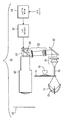
도 1은 오늘날의 펄스폭 변조 디스플레이 시스템의 개략적인 블록도.
도 2는 도 1의 디스플레이 시스템의 일부를 포함하는 색 휠의 정면도.
도 3 내지 도 6은, 본 발명에 따라 모션 아티팩트를 저감하도록 도 1의 디스플레이 시스템 내에서 픽셀들중 하나의 대응 색의 밝기를 제어하는 펄스폭 세그먼트의 복수의 시퀀스의 각각을 도시하는 펄스 맵을 일괄적으로 도시하는 도면들.1 is a schematic block diagram of a current pulse width modulated display system.
2 is a front view of a color wheel incorporating a portion of the display system of FIG.
3-6 show pulse maps illustrating each of a plurality of sequences of pulse-width segments controlling the brightness of a corresponding color of one of the pixels within the display system of FIG. 1 to reduce motion artifacts in accordance with the present invention. Figures collectively shown.
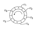
도 1은 2001년 6월 Texas Instruments에서 공개한 애플리케이션 리포트 "Single Panel DLPTM Projection System Optics"에 기재한 종류의 오늘날의 펄스폭 변조된 순차 디스플레이 시스템(10)을 나타낸다. 이 시스템(10)은 색 휠(14)을 통해 램프로부터의 광을 인터그레이터 로드((integrator rod; 15) 내로 반사하는 파라볼릭 반사기(13)의 초점에 위치한 램프(12)를 포함한다. 모터(16)는 색 휠(14)을 회전시켜 적색, 녹색, 및 청색인 삼원색 윈도우의 각각을 램프(12)와 인터그레이터 로드(15) 간에 배치한다. 도 2에 도시한 예시적인 실시예에서, 색 휠(14)은 직경 방향으로 대향하는 적색, 녹색, 및 청색 컬러 윈도우(171 및 174, 172 및 175, 173 및 176)를 각각 구비한다. 따라서, 모터(16)가 도 2의 색 휠(14)을 반시계 방향으로 회전시킬 때, 적색, 녹색, 및 청색 광은 도 1의 인터그레이터 로드(15)와 충돌한다. 실제로, 모터(16)는 충분한 고속으로 색 휠(14)을 회전시켜 1/60초의 프레임 간격동안 적색, 녹색, 및 청색 광 각각이 인터그레이터 로드와 4번 충돌하여, 그 프레임 간격 내에 인터리브된 4개의 적색, 4개의 녹색, 및 4개의 청색인 12개의 색 이미지를 생성하게 된다.FIG. 1 illustrates today's pulse width modulated
도 1을 참조하면, 인터그레이터 로드(15)는 램프(12)로부터의 광을 집광하고, 이것은 색 휠(14)의 적색, 녹색, 및 청색 컬러 윈도우의 연속하는 하나를 통과하여 릴레이 광학기 세트(18) 상으로 향한다. 릴레이 광학기(18)는 광을 폴드 미러(20)와 충돌하는 복수의 병행 빔으로 확산하고, 이 미러는 그 빔을 한 세트의 렌즈(22)를 통해 내부 전반사(TIR) 프리즘(23) 상으로 반사한다. TIR 프리즘(23)은, 투영 렌즈(26) 내로 그리고 스크린(28) 상으로의 선택적 반사를 위해 평행 광 빔을 Texas Instruments사가 제조한 DMD 장치와 같은 디지털 마이크로미러 장치(DMD; 24) 상으로 반사한다.Referring to FIG. 1, the
DMD(24)는 어레이로 배열된 복수의 개별적인 마이크로미러(도시하지 않음)를 구비하는 반도체 장치의 형태를 취한다. 예를 들어, Texas Instruments사에 의해 제조 및 판매되는 DMD는 720행 1280열의 마이크로미러 어레이를 구비하고, 그 결과 스크린(28)상으로 투영된 픽쳐에서 921,600개의 픽셀을 생성한다. 다른 DMD들은 상이하게 배열된 마이크로미러를 구비할 수 있다. 상기한 바와 같이, DMD에서의 각 마이크로미러는, 드라이버 셀에서 전회에 래치된 이진 비트 상태에 응답하여 대응 드라이버 셀(도시하지 않음)의 제어하에 제한된 호로 피봇한다. 각 마이크로미러는 드라이버 셀에 인가된 래치 비트가 "1"인지 또는 "0"인지의 여부에 따라 각각 제1 및 제2 위치중 하나로 회전한다. 각 마이크로미러가 제1 위치로 피봇되면, 각 마이크로미러는 광을 렌즈(26) 내로 그리고 스크린(28) 상으로 반사하여 대응 픽셀을 조명한다. 각 마이크로미러가 제2 위치로 피봇된 상태로 유지되면, 대응 픽셀은 어둡게 보인다. 각 마이크로미러가 투영 렌즈(26)를 통해 광을 스크린(28) 상으로 반사하는 전체 지속기간(마이크로미러 듀티 사이클)은 픽셀 밝기를 결정한다.The
DMD(24)에서의 개별적인 드라이버 셀은, 당해 기술에 알려져 있으며 (1994년 10월) International Workshop on HDTV에서 R.J. Grove 등의 "High Definition Display System Based on Micromirror Device" 문헌에 기재된 회로부에 의해 예시되는 종류의 드라이버 회로(30)로부터의 구동 신호를 수신한다. 드라이버 회로(30)는, 프로세서(31)에 의해 드라이버 회로에 인가되는 펄스폭 세그먼트들의 시퀀스에 따라 DMD(24)에서 드라이버 셀을 위한 구동 신호를 생성한다. 각 펄스폭 세그먼트는 상이한 시간 지속기간의 펄스들의 스트링을 포함하며, 각 펄스의 상태는 마이크로미러가 그 펄스의 지속기간동안 온 상태로 유지되는지 또는 오프 상태로 유지되는지의 여부를 결정한다. (때때로, 최하위 비트(LSB)라고도 칭하는) 하나의 펄스폭 세그먼트 내에서 발생할 수 있는 가능한 가장 짧은 펄스(즉, 1 펄스)는 전형적으로 15 마이크로초 지속기간을 갖는 반면, 그 세그먼트에서 펄스들이 길어질수록 각 펄스는 하나의 LSB보다 긴 지속기간을 갖는다. 실제로, 펄스폭 세그먼트 내의 각 펄스는, 대응 펄스가 턴온 상태인지 또는 턴오프 상태인지의 여부를 결정하는 상태를 갖는 디지털 비트 스트림 내의 비트(이하, "픽셀 제어" 비트로서 설명함)에 대응한다. "1" 비트는 턴온된 펄스를 나타내는 반면, "0" 비트는 턴오프된 펄스를 나타낸다. 소정의 색을 위한 모든 펄스폭 세그먼트에서 작동된 펄스들의 전체 합(지속기간)은 그 색을 위한 대응하는 픽셀의 밝기를 제어한다.Individual driver cells in the
드라이버 회로(31)는 프레임당 모든 픽셀을 위해 색마다 각각 4개의 개별적인 펄스폭 세그먼트를 생성한다. 따라서, 각 프레임 간격동안, 드라이버 회로(31)는 4개의 적색, 4개의 청색, 및 4개의 녹색인 12개 세그먼트들의 펄스를 위한 픽셀 제어 비트를 생성한다. DMD(24)로의 픽셀 제어 비트 전송은 색 휠의 회전에 동기화되며 따라서 소정의 색을 위한 각 세그먼트가 DMD(24) 상의 조명을 위한 그 색의 외관에 대응된다. 픽셀 밝기를 증가하기 위해, 드라이버 회로(31)는 저 밝기 레벨에서 전회에 비작동된 하나 이상의 펄스를 작동시킨다. 펄스폭 세그먼트 내의 펄스들의 코딩 기술에 따라, 특정한 밝기 레벨에서 작동된 펄스는 고 밝기 레벨에서 비작동된다. 밝기의 증분 증가를 얻기 위해 다른 세그먼트 내의 펄스들을 작동시키는 한편 소정의 세그먼트 내의 펄스들을 비작동시키게 되면 강도 과도현상에 대한 광 재분포 영향 때문에 모션 아티팩트가 발생할 수 있다.The
본 발명의 원리에 따라, 드라이버 회로(31)는 비작동되는(턴오프되는) 펄스들로 작동되는(턴온되는) 펄스들 간의 근접 조정을 달성한다. 특히, 드라이버 회로(31)는, 밝기의 증분 변경시에 하나의 세그먼트 내에서 작동되는 펄스들의 전체 폭 및 동일한 세그먼트 내에서 비작동되는 펄스들의 전체 폭을 거의 균등하게 하도록 작동 및 비작동되는 펄스들을 조정한다. 어느 경우에서든, 턴오프된 세그먼트에서의 모든 펄스들의 합보다 작은, 턴온되는 세그먼트에서의 모든 펄스들의 합은 밝기 변경을 균등하게 한다.In accordance with the principles of the present invention, the
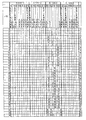
이러한 근접 조정이 작동되는 펄스들과 비작동되는 펄스들 간에 발생하는 방식을 가장 잘 이해하려면, 본 발명에 따라 소정의 색에 대한 밝기 레벨(#1 내지 #255; 8비트 해상도)의 각각을 얻기 위한 펄스폭 세그먼트들의 펄스 맵을 총괄적으로 나타내는 도 3 내지 도 6을 참조한다. 가장 어두운 넌제로 밝기 레벨(레벨 #1)은, 예시한 실시예에서 제1 픽셀 밝기 경계를 구성하며, 세그먼트 3에서 1-LSB 펄스로 시작한다. 픽셀 밝기가 밝기 레벨 #1을 초과하여 증가하게 되면, 작동된 펄스는, 이진 코딩을 채용할 때 제1 63개의 밝기 레벨용 세그먼트 3에 속하게 되며, 밝기 레벨 #63이 제2 밝기 경계를 구성한다. 제1 63개의 픽셀 밝기 레벨 내에서, 세그먼트 3 내에서 작동되는 펄스들의 전체 폭은, 나머지 세그먼트들 내의 펄스가 픽셀 밝기 레벨 #64에 도달할 때까지 비작동 상태로 유지되기 때문에 본 발명의 원리에 따라 비작동되는 펄스와 거의 균등하게 유지된다.To best understand how this proximity adjustment occurs between activated and non-operated pulses, obtain each of the brightness levels (# 1 to # 255; 8-bit resolution) for a given color in accordance with the present invention. Reference is made to FIGS. 3 to 6 collectively showing a pulse map of pulse width segments for the sake of brevity. The darkest non-zero brightness level (level # 1) constitutes the first pixel brightness boundary in the illustrated embodiment, starting with a 1-LSB pulse in
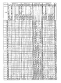
본 발명의 원리에 따라 펄스 작동 및 비작동 간에 조정이 발생하는 방식은 밝기 레벨 #63보다 높은 픽셀 밝기 레벨에서 보다 더 명백해진다. 이 픽셀 밝기 레벨을 초과하면, 세그먼트 1, 2, 4에서 펄스를 갖는 6개의 펄스 조합이 존재한다. 일예는, 도 4에 도시한 바와 같이 픽셀 밝기 레벨 #74로부터 밝기 레벨 #75로의 증분 트랜지션이다. 픽셀 밝기에서 이러한 증분 증가를 얻기 위해, 세그먼트 1, 2, 4 에 대하여 하나씩인 3개의 4-LSB 펄스들의 조합은 작동되어야 하는 한편, 이러한 3개 세그먼트에서 펄스들을 비작동시켜야 한다. 도 4로부터 알 수 있듯이, 세그먼트 1에서, 하나의 2-LSB 펄스 및 2개의 1-LSB 펄스들은 비작동되어 세그먼트 1에서 작동된 4-LSB 펄스를 평형시킨다(counterbalance). 펄스들의 동일한 작동 및 비작동이 세그먼트 4에서 발생한다. 세그먼트 2에서, 하나의 4-LSB 펄스가 작동되는 한편 하나의 1-LSB 펄스 및 하나의 2-LSB 펄스가 비작동된다. 이 1-LSB 차이는 이들 2개 픽셀 밝기 레벨 간의 밝기 증분을 구현한다. 유사한 전략이 하나를 제외하고 다른 증분 밝기 트랜지션을 달성한다. 픽셀 밝기 레벨 #158로부터 레벨 #159로의 트랜지션은, 31개의 LSB 펄스들이 비작동되는 동안 총 33개의 작동된 LSB 펄스들을 갖는 세그먼트 2와 함께, 도 5에 도시한 바와 같이 세그먼트 3에서 비작동된 하나의 1-LSB를 포함하며 동일한 세그먼트에서 작동되는 다른 펄스들을 갖지 않는다. 이것은 도 3 내지 도 6에 도시한 바와 같이 세그먼트 단위로 작동된 펄스들 및 비작동된 펄스들의 전체 가중치를 균등하게 하고자 하는 원리를 위배할 뿐이다. 이러한 위배는 사소한 것이며 보이지 않을 정도로 매우 높은 밝기에서 발생한다.According to the principles of the present invention, the manner in which the adjustment takes place between pulse actuation and non-actuation becomes more apparent at pixel brightness levels higher than
상기한 설명은, 밝기의 증분 변경이 있을 때, 각 세그먼트 내에서 작동되고 비작동되는 펄스들의 전체 폭을 실질적으로 균등화함으로써 펄스폭 변조 디스플레이 시스템에서 모션 아티팩트를 저감하는 기술을 나타낸다.The above description shows a technique for reducing motion artifacts in a pulse width modulated display system by substantially equalizing the overall width of pulses activated and deactivated within each segment when there is an incremental change in brightness.
18: 릴레이 광학기
20: 폴드 미러
22: 렌즈
23: 전반사(TIR) 프리즘
24: DMD
28: 스크린
30: 드라이버 회로
31: 펄스폭 세그먼트 18: relay optics
20: fold mirror
22: lens
23: Total Reflection (TIR) Prism
24: DMD
28: screen
30: driver circuit
31: pulse width segment
Claims (1)
A method of manipulating a pulse width modulated display system having a plurality of pixels in which illumination of each pixel is controlled in response to an operational state of the pulses within a sequence of pulse width segments.
Applications Claiming Priority (2)
| Application Number | Priority Date | Filing Date | Title |
|---|---|---|---|
| US43075102P | 2002-12-04 | 2002-12-04 | |
| US60/430,751 | 2002-12-04 |
Related Parent Applications (1)
| Application Number | Title | Priority Date | Filing Date |
|---|---|---|---|
| KR1020057010106A Division KR101044212B1 (en) | 2002-12-04 | 2003-07-07 | Pulse width modulated display with equalized pulse width segments |
Publications (1)
| Publication Number | Publication Date |
|---|---|
| KR20100114527A true KR20100114527A (en) | 2010-10-25 |
Family
ID=32507654
Family Applications (2)
| Application Number | Title | Priority Date | Filing Date |
|---|---|---|---|
| KR1020107018675A KR20100114527A (en) | 2002-12-04 | 2003-07-07 | Pulse width modulated display with equalized pulse width segments |
| KR1020057010106A KR101044212B1 (en) | 2002-12-04 | 2003-07-07 | Pulse width modulated display with equalized pulse width segments |
Family Applications After (1)
| Application Number | Title | Priority Date | Filing Date |
|---|---|---|---|
| KR1020057010106A KR101044212B1 (en) | 2002-12-04 | 2003-07-07 | Pulse width modulated display with equalized pulse width segments |
Country Status (7)
| Country | Link |
|---|---|
| US (1) | US7245327B2 (en) |
| EP (1) | EP1568217A4 (en) |
| JP (2) | JP5851672B2 (en) |
| KR (2) | KR20100114527A (en) |
| CN (1) | CN100388797C (en) |
| AU (1) | AU2003247894A1 (en) |
| WO (1) | WO2004054252A1 (en) |
Families Citing this family (7)
| Publication number | Priority date | Publication date | Assignee | Title |
|---|---|---|---|---|
| EP1568217A4 (en) * | 2002-12-04 | 2009-06-03 | Thomson Licensing | Pulse width modulated display with equalized pulse width segments |
| KR100686070B1 (en) | 2004-10-18 | 2007-02-23 | 엘지전자 주식회사 | Method and apparatus of controlling brightness in display |
| US20080122992A1 (en) * | 2005-01-28 | 2008-05-29 | Thomson Licensing S.A. | Sequential Display With Motion Adaptive Processing for a Dmd Projector |
| US7290883B2 (en) * | 2005-03-24 | 2007-11-06 | Tte Tchnology, Inc. | System and method for projecting video onto a screen |
| TWI261462B (en) * | 2005-04-21 | 2006-09-01 | Optoma Corp | Optical projection apparatus |
| CA3123801C (en) | 2013-05-07 | 2024-02-20 | Dolby Laboratories Licensing Corporation | Multi-half-tone imaging and dual modulation projection/dual modulation laser projection |
| US10341622B2 (en) | 2013-05-07 | 2019-07-02 | Dolby Laboratories Licensing Corporation | Multi-half-tone imaging and dual modulation projection/dual modulation laser projection |
Family Cites Families (15)
| Publication number | Priority date | Publication date | Assignee | Title |
|---|---|---|---|---|
| EP0664917B1 (en) * | 1992-10-15 | 2004-03-03 | Texas Instruments Incorporated | Display device |
| US6362835B1 (en) | 1993-11-23 | 2002-03-26 | Texas Instruments Incorporated | Brightness and contrast control for a digital pulse-width modulated display system |
| US5619228A (en) * | 1994-07-25 | 1997-04-08 | Texas Instruments Incorporated | Method for reducing temporal artifacts in digital video systems |
| US5777589A (en) * | 1995-04-26 | 1998-07-07 | Texas Instruments Incorporated | Color display system with spatial light modulator(s) having color-to-color variations in data sequencing |
| CA2184129A1 (en) | 1995-08-31 | 1997-03-01 | Donald B. Doherty | Bit-splitting for pulse width modulated spatial light modulator |
| JP3322809B2 (en) * | 1995-10-24 | 2002-09-09 | 富士通株式会社 | Display driving method and apparatus |
| US5940142A (en) * | 1995-11-17 | 1999-08-17 | Matsushita Electronics Corporation | Display device driving for a gray scale expression, and a driving circuit therefor |
| US5774196A (en) * | 1996-06-13 | 1998-06-30 | Texas Instruments Incorporated | Method and apparatus of aligning color modulation data to color wheel filter segments |
| JPH10177370A (en) * | 1996-10-16 | 1998-06-30 | Oki Lsi Technol Kansai:Kk | Multilevel output circuit and liquid crystal display device |
| US6108053A (en) | 1997-05-30 | 2000-08-22 | Texas Instruments Incorporated | Method of calibrating a color wheel system having a clear segment |
| US6246185B1 (en) | 1998-12-31 | 2001-06-12 | Texas Instruments Incorporated | High frequency ballast for high intensity discharge lamps |
| JP2000259126A (en) * | 1999-03-04 | 2000-09-22 | Matsushita Electric Ind Co Ltd | Gradational display method |
| JP4008178B2 (en) * | 1999-03-04 | 2007-11-14 | 松下電器産業株式会社 | Gradation display method |
| EP1568217A4 (en) * | 2002-12-04 | 2009-06-03 | Thomson Licensing | Pulse width modulated display with equalized pulse width segments |
| US20060108053A1 (en) * | 2004-11-19 | 2006-05-25 | Hart James M | Hot application of apex on a tire building machine |
-
2003
- 2003-07-07 EP EP03812757A patent/EP1568217A4/en not_active Ceased
- 2003-07-07 KR KR1020107018675A patent/KR20100114527A/en not_active Application Discontinuation
- 2003-07-07 KR KR1020057010106A patent/KR101044212B1/en active IP Right Grant
- 2003-07-07 US US10/537,113 patent/US7245327B2/en not_active Expired - Lifetime
- 2003-07-07 CN CNB038255111A patent/CN100388797C/en not_active Expired - Lifetime
- 2003-07-07 JP JP2004559033A patent/JP5851672B2/en not_active Expired - Lifetime
- 2003-07-07 WO PCT/US2003/021155 patent/WO2004054252A1/en active Application Filing
- 2003-07-07 AU AU2003247894A patent/AU2003247894A1/en not_active Abandoned
-
2014
- 2014-07-24 JP JP2014150655A patent/JP6021859B2/en not_active Expired - Lifetime
Also Published As
| Publication number | Publication date |
|---|---|
| JP5851672B2 (en) | 2016-02-03 |
| WO2004054252A1 (en) | 2004-06-24 |
| US7245327B2 (en) | 2007-07-17 |
| JP6021859B2 (en) | 2016-11-09 |
| JP2006509257A (en) | 2006-03-16 |
| KR20050084145A (en) | 2005-08-26 |
| EP1568217A4 (en) | 2009-06-03 |
| AU2003247894A1 (en) | 2004-06-30 |
| JP2014225034A (en) | 2014-12-04 |
| CN1703903A (en) | 2005-11-30 |
| US20060203134A1 (en) | 2006-09-14 |
| CN100388797C (en) | 2008-05-14 |
| KR101044212B1 (en) | 2011-06-29 |
| EP1568217A1 (en) | 2005-08-31 |
Similar Documents
| Publication | Publication Date | Title |
|---|---|---|
| JP6021859B2 (en) | Pulse width modulation display with uniform pulse width segments | |
| JP2014044440A (en) | Spoke light compensation for motion artifact reduction | |
| MXPA06012725A (en) | Pixel shift display with minimal noise. | |
| US6781737B2 (en) | Pulse width modulated display with hybrid coding | |
| US7248253B2 (en) | Pulse width modulated display with improved motion appearance | |
| US7495642B2 (en) | Sequential multi-segment pulse width modulated display system | |
| KR101015029B1 (en) | Pulse width modulated display with hybrid coding |
Legal Events
| Date | Code | Title | Description |
|---|---|---|---|
| A107 | Divisional application of patent | ||
| A201 | Request for examination | ||
| E902 | Notification of reason for refusal | ||
| E601 | Decision to refuse application |