KR20100101532A - Optical encoder - Google Patents
Optical encoder Download PDFInfo
- Publication number
- KR20100101532A KR20100101532A KR1020100020278A KR20100020278A KR20100101532A KR 20100101532 A KR20100101532 A KR 20100101532A KR 1020100020278 A KR1020100020278 A KR 1020100020278A KR 20100020278 A KR20100020278 A KR 20100020278A KR 20100101532 A KR20100101532 A KR 20100101532A
- Authority
- KR
- South Korea
- Prior art keywords
- slit
- annular slit
- annular
- optical encoder
- rotating disk
- Prior art date
Links
- 230000003287 optical effect Effects 0.000 title claims abstract description 129
- 238000001514 detection method Methods 0.000 claims abstract description 215
- 238000006073 displacement reaction Methods 0.000 claims description 169
- 238000000034 method Methods 0.000 claims description 24
- 230000001678 irradiating effect Effects 0.000 claims description 10
- 230000003252 repetitive effect Effects 0.000 claims 1
- 239000011295 pitch Substances 0.000 abstract description 36
- 230000005540 biological transmission Effects 0.000 abstract description 2
- 230000035515 penetration Effects 0.000 abstract 1
- 238000006243 chemical reaction Methods 0.000 description 68
- 238000010586 diagram Methods 0.000 description 19
- 230000008569 process Effects 0.000 description 11
- 238000004364 calculation method Methods 0.000 description 8
- 238000003672 processing method Methods 0.000 description 8
- 239000000758 substrate Substances 0.000 description 4
- 230000000694 effects Effects 0.000 description 3
- 230000008859 change Effects 0.000 description 2
- 230000002159 abnormal effect Effects 0.000 description 1
- 230000015572 biosynthetic process Effects 0.000 description 1
- 230000006870 function Effects 0.000 description 1
- 230000003340 mental effect Effects 0.000 description 1
- 238000012986 modification Methods 0.000 description 1
- 230000004048 modification Effects 0.000 description 1
- 230000004044 response Effects 0.000 description 1
Images


Classifications
-
- G—PHYSICS
- G01—MEASURING; TESTING
- G01D—MEASURING NOT SPECIALLY ADAPTED FOR A SPECIFIC VARIABLE; ARRANGEMENTS FOR MEASURING TWO OR MORE VARIABLES NOT COVERED IN A SINGLE OTHER SUBCLASS; TARIFF METERING APPARATUS; MEASURING OR TESTING NOT OTHERWISE PROVIDED FOR
- G01D5/00—Mechanical means for transferring the output of a sensing member; Means for converting the output of a sensing member to another variable where the form or nature of the sensing member does not constrain the means for converting; Transducers not specially adapted for a specific variable
- G01D5/26—Mechanical means for transferring the output of a sensing member; Means for converting the output of a sensing member to another variable where the form or nature of the sensing member does not constrain the means for converting; Transducers not specially adapted for a specific variable characterised by optical transfer means, i.e. using infrared, visible, or ultraviolet light
- G01D5/32—Mechanical means for transferring the output of a sensing member; Means for converting the output of a sensing member to another variable where the form or nature of the sensing member does not constrain the means for converting; Transducers not specially adapted for a specific variable characterised by optical transfer means, i.e. using infrared, visible, or ultraviolet light with attenuation or whole or partial obturation of beams of light
- G01D5/34—Mechanical means for transferring the output of a sensing member; Means for converting the output of a sensing member to another variable where the form or nature of the sensing member does not constrain the means for converting; Transducers not specially adapted for a specific variable characterised by optical transfer means, i.e. using infrared, visible, or ultraviolet light with attenuation or whole or partial obturation of beams of light the beams of light being detected by photocells
- G01D5/347—Mechanical means for transferring the output of a sensing member; Means for converting the output of a sensing member to another variable where the form or nature of the sensing member does not constrain the means for converting; Transducers not specially adapted for a specific variable characterised by optical transfer means, i.e. using infrared, visible, or ultraviolet light with attenuation or whole or partial obturation of beams of light the beams of light being detected by photocells using displacement encoding scales
- G01D5/3473—Circular or rotary encoders
-
- G—PHYSICS
- G01—MEASURING; TESTING
- G01D—MEASURING NOT SPECIALLY ADAPTED FOR A SPECIFIC VARIABLE; ARRANGEMENTS FOR MEASURING TWO OR MORE VARIABLES NOT COVERED IN A SINGLE OTHER SUBCLASS; TARIFF METERING APPARATUS; MEASURING OR TESTING NOT OTHERWISE PROVIDED FOR
- G01D5/00—Mechanical means for transferring the output of a sensing member; Means for converting the output of a sensing member to another variable where the form or nature of the sensing member does not constrain the means for converting; Transducers not specially adapted for a specific variable
- G01D5/26—Mechanical means for transferring the output of a sensing member; Means for converting the output of a sensing member to another variable where the form or nature of the sensing member does not constrain the means for converting; Transducers not specially adapted for a specific variable characterised by optical transfer means, i.e. using infrared, visible, or ultraviolet light
- G01D5/32—Mechanical means for transferring the output of a sensing member; Means for converting the output of a sensing member to another variable where the form or nature of the sensing member does not constrain the means for converting; Transducers not specially adapted for a specific variable characterised by optical transfer means, i.e. using infrared, visible, or ultraviolet light with attenuation or whole or partial obturation of beams of light
- G01D5/34—Mechanical means for transferring the output of a sensing member; Means for converting the output of a sensing member to another variable where the form or nature of the sensing member does not constrain the means for converting; Transducers not specially adapted for a specific variable characterised by optical transfer means, i.e. using infrared, visible, or ultraviolet light with attenuation or whole or partial obturation of beams of light the beams of light being detected by photocells
- G01D5/347—Mechanical means for transferring the output of a sensing member; Means for converting the output of a sensing member to another variable where the form or nature of the sensing member does not constrain the means for converting; Transducers not specially adapted for a specific variable characterised by optical transfer means, i.e. using infrared, visible, or ultraviolet light with attenuation or whole or partial obturation of beams of light the beams of light being detected by photocells using displacement encoding scales
- G01D5/34776—Absolute encoders with analogue or digital scales
- G01D5/34792—Absolute encoders with analogue or digital scales with only digital scales or both digital and incremental scales
- G01D5/34794—Optical encoders using the Vernier principle, i.e. incorporating two or more tracks having a (n, n+1, ...) relationship
-
- G—PHYSICS
- G01—MEASURING; TESTING
- G01D—MEASURING NOT SPECIALLY ADAPTED FOR A SPECIFIC VARIABLE; ARRANGEMENTS FOR MEASURING TWO OR MORE VARIABLES NOT COVERED IN A SINGLE OTHER SUBCLASS; TARIFF METERING APPARATUS; MEASURING OR TESTING NOT OTHERWISE PROVIDED FOR
- G01D5/00—Mechanical means for transferring the output of a sensing member; Means for converting the output of a sensing member to another variable where the form or nature of the sensing member does not constrain the means for converting; Transducers not specially adapted for a specific variable
- G01D5/26—Mechanical means for transferring the output of a sensing member; Means for converting the output of a sensing member to another variable where the form or nature of the sensing member does not constrain the means for converting; Transducers not specially adapted for a specific variable characterised by optical transfer means, i.e. using infrared, visible, or ultraviolet light
- G01D5/32—Mechanical means for transferring the output of a sensing member; Means for converting the output of a sensing member to another variable where the form or nature of the sensing member does not constrain the means for converting; Transducers not specially adapted for a specific variable characterised by optical transfer means, i.e. using infrared, visible, or ultraviolet light with attenuation or whole or partial obturation of beams of light
- G01D5/34—Mechanical means for transferring the output of a sensing member; Means for converting the output of a sensing member to another variable where the form or nature of the sensing member does not constrain the means for converting; Transducers not specially adapted for a specific variable characterised by optical transfer means, i.e. using infrared, visible, or ultraviolet light with attenuation or whole or partial obturation of beams of light the beams of light being detected by photocells
- G01D5/36—Forming the light into pulses
Landscapes
- Physics & Mathematics (AREA)
- General Physics & Mathematics (AREA)
- Optical Transform (AREA)
Abstract
Description
본 발명은 모터 등 회전체의 위치 결정용 센서로서 사용되는 광학식 인코더에 관한 것이다.
The present invention relates to an optical encoder used as a sensor for positioning a rotating body such as a motor.
종래, 회전체의 회전축의 절대 각도를 고분해능으로 검출하기 위해서, 회전축의 회전 중심에 대해 편심된 복수의 동심원의 환상 슬릿을 회전 디스크에 형성하고, 상기 동심원 슬릿의 편심량을 검출하며, 이 편심량으로부터 회전 디스크의 절대 각도를 검출하는 광학식 인코더가 있었다(예컨대, 일본 특허 출원 제 2007-223499호(일본 특허 공개 제 2009-058243호 공보 참조). 즉, 회전축 주위로 동심원 슬릿이 회전하면, 그 동심원 슬릿이 회전축에 대해 편심되어서 형성되어 있기 때문에, 회전축으로부터 동심원 슬릿의 검출 위치까지의 거리는 회전 각도에 따라 변화된다. 그래서, 이 광학식 인코더에 의하면, 이 거리에 따라 회전 디스크의 회전 각도를 검출하고 있었다.
Conventionally, in order to detect the absolute angle of the rotating shaft of a rotating body with high resolution, a plurality of concentric annular slits eccentric with respect to the center of rotation of the rotating shaft are formed on the rotating disk, the amount of eccentricity of the concentric circular slit is detected, and the rotation is made from this eccentric amount. There was an optical encoder for detecting the absolute angle of the disk (for example, Japanese Patent Application No. 2007-223499 (see Japanese Patent Laid-Open Publication No. 2009-058243), ie, if the concentric slit rotates around the axis of rotation, the concentric slit is rotated). Since it is formed eccentrically with respect to the rotation axis, the distance from the rotation axis to the detection position of the concentric slit changes according to the rotation angle, and according to this optical encoder, the rotation angle of the rotation disk was detected according to this distance.
그러나, 이 광학식 인코더에서는, 우회전으로 θ도 회전한 경우와 좌회전으로 θ도 회전한 경우의 양자에서, 회전축으로부터 동심원 슬릿의 검출 위치까지의 거리는 같아지는 경우가 있다. 즉, 일본 특허 출원 제 2007-223499호에 기재된 광학식 인코더에서는 예컨대, 회전 디스크의 0도부터 180도, 또는 180도부터 360도(0도)의 반회전 내에서만 회전 각도를 산출할 수 있고, 그 이상 회전한 경우, 0도부터 180도의 범위에 있는지, 180도부터 360도(0도)의 범위에 있는지는 알 수 없다.However, in this optical encoder, the distance from the rotational axis to the detection position of the concentric slit may be the same in both the case where θ is rotated in the right rotation and the case is rotated θ in the left rotation. That is, in the optical encoder described in Japanese Patent Application No. 2007-223499, for example, the rotation angle can be calculated only within a half rotation of 0 to 180 degrees or 180 to 360 degrees (0 degrees) of the rotating disk. In the case of abnormal rotation, it is not known whether it is in the range of 0 to 180 degrees or in the range of 180 to 360 degrees (0 degrees).
또한, 동심원 슬릿을 검출하는 검출부를, 서로 90도 이격된 위치에, 2개소에 마련하고, 양 검출부에서 환상 슬릿의 위치를 검출하면, 양 검출부로부터 얻어지는 신호는 회전축의 회전 각도에 대해 환상 슬릿의 각각의 검출부까지의 거리에 대응하는 2상의 신호로 되기 때문에, 0부터 360도의 회전 각도를 산출할 수 있다. 그러나, 양 검출부를 서로 이격된 위치에 배치하기 때문에 소형화하는 것이 어렵다.
In addition, when two detection sections for detecting concentric slits are provided at positions spaced 90 degrees apart from each other, and the positions of the annular slits are detected by both detection sections, the signals obtained from both detection sections are obtained from the annular slits with respect to the rotation angle of the rotation axis. Since it becomes a two-phase signal corresponding to the distance to each detection part, the rotation angle of 0 to 360 degree can be calculated. However, it is difficult to miniaturize because the detectors are arranged at positions spaced apart from each other.
본 발명은 상술한 문제점을 해결하기 위해 안출된 것으로, 본 발명의 대표적인 구성은 다음과 같다.The present invention has been made to solve the above problems, the typical configuration of the present invention is as follows.
본 발명의 일 측면에 따라서, 회전축에 부착되고, 상기 회전축의 회전에 따라 회전 가능한 회전 디스크와, According to an aspect of the present invention, a rotating disk attached to a rotating shaft and rotatable in accordance with the rotation of the rotating shaft,
상기 회전 디스크에 마련되고, 상기 회전 디스크의 회전 중심으로 대해 편심되게 형성된 복수의 등피치의 동심원 슬릿 패턴을 포함하는 환상 슬릿과, An annular slit provided on said rotating disk, said annular slit comprising a plurality of equal pitch concentric slit patterns formed eccentrically with respect to the rotation center of said rotating disk;
상기 환상 슬릿에 광을 조사하는 광원과, A light source for irradiating light to the annular slit;
상기 광원으로부터 조사되어 상기 환상 슬릿에서 투과 또는 반사된 투과광 또는 반사광을 검출하여 검출 신호를 출력하는 절대치용 검출부와, An absolute value detector for detecting transmitted light or reflected light transmitted from or reflected by the annular slit and outputting a detection signal;
상기 절대치용 검출부에서 검출된 검출 신호에 기초해서, 상기 회전 디스크의 절대 회전 각도를 검출하는 신호 처리 장치A signal processing device for detecting an absolute rotation angle of the rotating disk based on the detection signal detected by the absolute value detecting unit.
를 구비하되, Respectively,
상기 환상 슬릿은 서로 다른 방향으로 편심된 제 1 환상 슬릿 및 제 2 환상 슬릿을 갖고, The annular slit has a first annular slit and a second annular slit eccentric in different directions,
상기 절대치용 검출부는 상기 제 1 환상 슬릿에 대응하는 제 1 검출부 및 상기 제 2 환상 슬릿에 대응하는 제 2 검출부를 갖는, 광학식 인코더가 제공된다.
The absolute detector is provided with an optical encoder having a first detector corresponding to the first annular slit and a second detector corresponding to the second annular slit.
도 1은 본 발명의 실시예 1을 나타내는 광학식 인코더의 측면도,
도 2는 실시예 1에 있어서의 광학식 인코더의 평면도,
도 3은 실시예 1에 있어서의 환상 슬릿의 패턴예를 나타내는 모식도,
도 4는 실시예 1에 있어서의 제 1 고정 슬릿의 평면도,
도 5는 실시예 1에 있어서의 제 1 수광 소자의 평면도,
도 6은 실시예 1에 있어서 회전 디스크가 회전했을 때의 회전 각도 θ와 거리 L1 및 거리 L2와의 관계를 나타내는 모식도,
도 7은 실시예 1에 있어서의 회전 각도 θ와 거리 L1 및 거리 L2의 관계를 나타내는 모식도,
도 8은 실시예 1에 있어서의 회전 각도 θ와 거리 L1 및 L2의 관계를 나타내는 그래프이다.
도 9는 실시예 1에 있어서의 광학식 인코더의 신호 처리 장치의 제 1 예를 나타내는 블록도,
도 10는 실시예 1에 있어서의 신호 처리의 단계를 나타내는 흐름도,
도 11은 실시예 1에 있어서의 광학식 인코더의 신호 처리 장치의 제 2 예를 나타내는 블록도,
도 12는 실시예 1에 있어서의 신호 처리의 단계를 나타내는 흐름도,
도 13은 실시예 1에 있어서의 광학식 인코더의 신호 처리 장치의 제 3 예를 나타내는 블록도,
도 14는 본 실시예에 있어서의 신호 처리의 단계를 나타내는 흐름도,
도 15는 본 발명의 실시예 2를 나타내는 광학식 인코더의 측면도,
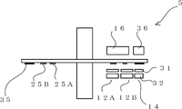
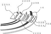
도 16은 실시예 2에 있어서의 회전 디스크와 광원 슬릿 및 인덱스 슬릿의 배치를 나타내는 사시도,
도 17은 도 16에 광원과 수광 소자를 더해서 표시한 사시도,
도 18은 회전 디스크의 중심이 회전 중심에 대해 어긋나게 부착된 경우의 회전 디스크의 상태를 나타내는 평면도,
도 19는 도 18의 위치로부터 회전 각도 θ만큼 회전한 경우의 회전 디스크의 상태를 나타내는 평면도,
도 20는 도 19의 주요부 확대도,
도 21은 본 발명의 실시예 3을 나타내는 광학식 인코더의 측면도,
도 22는 실시예 3에 있어서의 광학식 인코더의 평면도,
도 23은 실시예 3에 있어서의 환상 슬릿의 패턴예를 나타내는 평면도,
도 24는 실시예 3에 있어서, 회전 디스크의 중심이 회전 중심에 대해 어긋나게 부착된 경우의 회전 디스크의 상태를 나타내는 평면도,
도 25는 도 24의 상태로부터 회전 디스크가 회전 각도 θ만큼 회전했을 때의 상태를 나타내는 평면도,
도 26은 도 25의 주요부 확대도,
도 27은 실시예 3에 있어서의 광학식 인코더의 신호 처리 장치의 제 1 예를 나타내는 블록도,
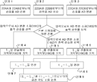
도 28은 실시예 3에 있어서의 신호 처리의 단계를 나타내는 흐름도,
도 29는 실시예 3에 있어서의 광학식 인코더의 신호 처리 장치의 제 2 예를 나타내는 블록도,
도 30는 실시예 3에 있어서의 광학식 인코더의 다른 신호 처리 방법의 흐름도,
도 31은 실시예 3에 있어서의 광학식 인코더의 신호 처리 장치의 제 3 예를 나타내는 블록도,
도 32는 실시예 3에 있어서의 광학식 인코더의 다른 신호 처리 방법의 흐름도,
도 33은 본 발명의 실시예 4를 나타내는 광학식 인코더의 측면도,
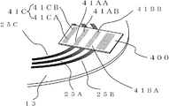
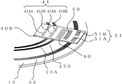
도 34는 실시예 4에 있어서의 광학식 인코더의 구성을 나타내는 사시도로, 회전 디스크와 광원 슬릿 및 인덱스 슬릿의 배치를 나타낸 도면,
도 35는 도 34에 광원과 수광 소자를 더해서 표시한 도면,
도 36은 본 발명의 실시예 5를 나타내는 광학식 인코더의 측면도,
도 37은 실시예 5에 있어서의 광학식 인코더의 평면도,
도 38은 본 발명의 실시예 6을 나타내는 광학식 인코더의 측면도,
도 39는 실시예 6에 있어서의 광학식 인코더의 구성을 나타내는 사시도로, 회전 디스크와, 광원 슬릿, 인크리멘탈용 광원 슬릿, 인덱스 슬릿(41) 및 인크리멘탈용 인덱스 슬릿의 배치를 나타낸 도면,
도 40는 도 39에 광원과 수광 소자(절대치용) 및 인크리멘탈용 수광 소자를 더해서 표시한 도면,
도 41은 본 발명의 실시예 7을 나타내는 광학식 인코더의 측면도,
도 42는 실시예 7에 있어서의 광학식 인코더의 구성을 나타내는 사시도로, 회전 디스크와 광원 슬릿 및 인덱스 슬릿의 배치를 나타낸 도면,
도 43은 도 42에 광원과 제 3 수광 소자를 더해서 표시한 도면,
도 44는 본 발명의 각 실시예에 따른 모터 및 모터 시스템의 구성을 나타내는 블록도이다. 1 is a side view of an optical
2 is a plan view of the optical encoder according to the first embodiment;
3 is a schematic diagram illustrating a pattern example of the annular slit in Example 1;
4 is a plan view of the first fixing slit in the first embodiment;
5 is a plan view of a first light receiving element in Example 1;
6 is a schematic diagram showing the relationship between the rotation angle θ, the distance L 1 and the distance L 2 when the rotating disk is rotated in Example 1;
7 is a schematic diagram illustrating the relationship between the rotation angle θ, the distance L 1, and the distance L 2 in Example 1;
8 is a graph showing the relationship between the rotation angle θ and the distances L 1 and L 2 in Example 1. FIG.
9 is a block diagram showing a first example of a signal processing apparatus of an optical encoder according to the first embodiment;
10 is a flowchart showing the steps of signal processing according to the first embodiment;
11 is a block diagram showing a second example of a signal processing apparatus of an optical encoder according to the first embodiment;
12 is a flowchart showing steps of signal processing in Example 1;
13 is a block diagram showing a third example of the signal processing apparatus of the optical encoder according to the first embodiment;
14 is a flowchart showing the steps of signal processing in the present embodiment;
15 is a side view of an optical encoder showing a second embodiment of the present invention;
16 is a perspective view showing the arrangement of the rotating disk, the light source slit and the index slit in the second embodiment;
FIG. 17 is a perspective view of a light source and a light receiving element added to FIG. 16;
18 is a plan view showing a state of the rotating disk when the center of the rotating disk is attached to the rotating center in an offset manner;
19 is a plan view showing a state of the rotating disk when rotating from the position of FIG. 18 by the rotation angle θ;
20 is an enlarged view of a main part of FIG. 19;
21 is a side view of an optical encoder showing a third embodiment of the present invention;
22 is a plan view of the optical encoder according to the third embodiment;
23 is a plan view showing a pattern example of an annular slit in Example 3;
24 is a plan view showing the state of the rotating disk when the center of the rotating disk is attached to the rotating center in the third embodiment;
25 is a plan view showing a state when the rotating disk is rotated by the rotation angle θ from the state of FIG. 24;
26 is an enlarged view of a main part of FIG. 25;
27 is a block diagram showing a first example of a signal processing apparatus of an optical encoder according to a third embodiment;
28 is a flowchart showing the steps of signal processing in Example 3;
29 is a block diagram showing a second example of the signal processing apparatus of the optical encoder according to the third embodiment;
30 is a flowchart of another signal processing method of the optical encoder according to the third embodiment;
31 is a block diagram showing a third example of the signal processing apparatus of the optical encoder according to the third embodiment;
32 is a flowchart of another signal processing method of the optical encoder according to the third embodiment;
33 is a side view of an optical encoder showing a fourth embodiment of the present invention;
Fig. 34 is a perspective view showing the structure of the optical encoder in the fourth embodiment, showing the arrangement of the rotating disk, the light source slit, and the index slit;
35 is a view showing the light source and the light receiving element added to FIG. 34;
36 is a side view of an optical encoder showing a fifth embodiment of the present invention;
37 is a plan view of the optical encoder according to the fifth embodiment;
38 is a side view of an optical encoder showing a sixth embodiment of the present invention;
Fig. 39 is a perspective view showing the configuration of the optical encoder in the sixth embodiment, showing the arrangement of a rotating disk, a light source slit, an incremental light source slit, an index slit 41, and an incremental index slit,
FIG. 40 is a view showing the light source, the light receiving element (for absolute value), and the incremental light receiving element in FIG. 39;
41 is a side view of an optical encoder representing a seventh embodiment of the present invention;
Fig. 42 is a perspective view showing the structure of the optical encoder in the seventh embodiment, showing the arrangement of the rotating disk, the light source slit, and the index slit;
FIG. 43 is a view showing the light source and the third light receiving element added to FIG. 42;
44 is a block diagram showing the configuration of a motor and a motor system according to each embodiment of the present invention.
이하, 본 발명의 실시예가 첨부된 도면을 참조로 설명될 것이다. 이 상세한 설명 및 첨부된 도면에서, 실질적으로 같은 기능 및 구성을 가진 구성 요소는 동일함 참조 번호로 표시되었으며, 이들 구성 요소의 반복 설명은 생략한다.
Hereinafter, embodiments of the present invention will be described with reference to the accompanying drawings. In this detailed description and the annexed drawings, components having substantially the same functions and configurations are denoted by the same reference numerals and repeated descriptions of these components are omitted.
<실시예 1>≪ Example 1 >
(실시예 1의 구성)(Configuration of Example 1)
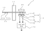
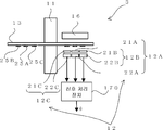
도 1은 본 발명의 실시예 1을 나타내는 광학식 인코더의 측면도, 도 2는 평면도이다. 한편, 도 2의 평면도는, 도 1을 종이면의 아래쪽으로부터 본 도면이다. 1 is a side view of an optical encoder according to a first embodiment of the present invention, and FIG. 2 is a plan view. On the other hand, the top view of FIG. 2 is a figure which looked at FIG. 1 from the bottom of a paper surface.
도 1 및 도 2에 나타낸 바와 같이, 본 실시예에 따른 광학식 인코더(1)는 크게 나눠서, 회전축(11)과, 회전 디스크(13)와, 환상 슬릿(25)과, 광원(16)과, 검출부(12)와, 신호 처리 장치(170)를 갖는다. As shown in Fig. 1 and Fig. 2, the
회전축(11)은 회전 각도를 측정하려 하는 회전체(도시 생략)가 일단에 접속되고, 상기 회전체의 회전에 따라 회전축(11)의 길이 방향의 회전 중심(100) 둘레로 회전한다. The rotating
회전 디스크(13)는 회전축(11)에 접속되어 상기 회전축(11)의 회전과 함께 회전 중심(100) 둘레로 회전 가능하게 형성된다. The
환상 슬릿(25)은 회전 디스크(13)에 마련되고, 회전 디스크(13)의 회전 중심(100)에 대해 편심되게 형성된 복수의 동 피치의 동심원 슬릿 패턴을 포함한다. 한편, 본 실시예에 있어서의 환상 슬릿(25)은 투과 슬릿으로서 형성된다. 또한, 환상 슬릿(25)은 두 종류의 환상 슬릿 즉, 제 1 환상 슬릿(25A)과, 제 2 환상 슬릿(25B)을 갖는다. The
제 1 환상 슬릿(25A)은, 도 2에 나타낸 바와 같이, 본 실시예에 따른 광학 인코더가 회전 디스크(13)의 회전 중심(100)에 대해 편심된 복수의 동심원 슬릿 패턴을 갖는다. 한편, 제 2 환상 슬릿(25B)은 회전 디스크(13)의 회전 중심(100)에 대해 제 1 환상 슬릿(25A)과는 다른 방향으로 편심된 복수의 동심원 슬릿 패턴을 갖는다. 단, 제 1 환상 슬릿(25A) 및 제 2 환상 슬릿(25B) 각각의 복수의 동심원 슬릿 패턴은 각 동심원의 중심으로부터의 경로가 다르고, 또한, 간격인 피치가 동일하게 되도록 마련된다. As shown in FIG. 2, the first annular slit 25A has a plurality of concentric slit patterns in which the optical encoder according to the present embodiment is eccentric with respect to the
검출부(12)는 원점(原點)용 검출부의 일례로, 제 1 검출부(12A)와, 제 2 검출부(12B)를 갖는다. 제 1 검출부(12A) 및 제 2 검출부(12B)는 각각 제 1 환상 슬릿(25A) 및 제 2 환상 슬릿(25B)에 대응하며, 고정 부재(도시 생략)에 마련된다. 또한, 제 1 검출부(12A) 및 제 2 검출부(12B)는 회전 디스크(13)의 직경 방향의 동일 직선축에 근접해서 배치되어 있다. The
제 1 검출부(12A)는 본 실시예에서는 제 1 고정 슬릿(21A)과 제 1 수광 소자(22A)를 갖고, 제 2 검출부(12B)는 제 2 고정 슬릿(21B)과 제 2 수광 소자(22B)를 갖는다. The first detection unit 12A has the first fixed slit 21A and the first light receiving element 22A in this embodiment, and the second detection unit 12B has the second fixed slit 21B and the second light receiving element 22B. Has
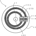
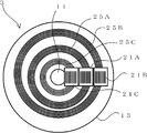
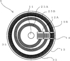
도 3은 환상 슬릿의 패턴예를 나타내는 모식도이다. It is a schematic diagram which shows the pattern example of an annular slit.
도 3에 나타낸 바와 같이, 제 1 환상 슬릿(25A)은 회전 디스크(13)의 중심(103)에 대해서 X축 방향으로 거리 d1만큼 편심된 점(101A)을 중심으로 한 반경 r1인 원을 중앙으로 해서 Δr1씩 반경이 다른 복수(도면에서는 5개)의 동심원 슬릿으로 형성되어 있다. 제 2 환상 슬릿(25B)은 회전 디스크(13)의 중심(103)에 대해 Y축 방향으로 거리 d2만큼 편심된 점(101B)을 중심으로 한 반경 r2인 원을 중앙으로 해서 Δr2씩 반경이 다른 복수(도면에서는 5개)의 동심원 슬릿으로 형성되어 있다. 그리고, 회전 디스크(13)의 중심(103)은 회전축(11)의 회전 중심(100)과 일치하도록 부착되어 있다. As shown in FIG. 3, the first annular slit 25A is a circle having a radius r 1 around the
즉, 본 실시예에 따른 광학식 인코더(1)는 회전 디스크(13)에, 회전 디스크(13)의 중심(103)에 대해 서로 다른 방향으로 편심되어 있는 2개의 환상 슬릿을 구비하고 있다. That is, the
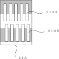
도 4는 제 1 고정 슬릿(21A)의 평면도이다. 4 is a plan view of the first fixing slit 21A.
제 1 고정 슬릿(21A)은 환상 슬릿과 동일 피치로, 복수의 평행 슬릿을 가진 A상(相)의 슬릿군(21AA)과, A상의 슬릿군(21AA)과는 개구부의 위상이 다른 B상의 슬릿군(21AB)이 형성되어 있다. The first fixed slit 21A has the same pitch as the annular slit and has a phase A slit group 21AA having a plurality of parallel slits and a phase B different from the slit group 21AA in the A phase. The slit group 21AB is formed.
도 5는 제 1 수광 소자의 평면도이다. 5 is a plan view of the first light receiving element.
A상의 슬릿군, B상의 슬릿군에 대응해서, 도 5와 같이, 제 1 수광 소자(22A)도 A상 수광부(22AA)와 B상 수광부(22AB)의 2개로 분할되어 있다. 도시하지 않지만, 마찬가지로, 제 2 고정 슬릿(21B)도 서로 위상이 다른 A상의 슬릿군(21BA)과, B상의 슬릿군(21BB)이 형성되고, 제 2 수광 소자(22B)는 A상 수광부(22BA)와 B상 수광부(22BB)의 2개로 분할되어 있다. Corresponding to the slit group of the A phase and the slit group of the B phase, as shown in FIG. 5, the first light receiving element 22A is also divided into two, an A phase light receiving part 22AA and a B phase light receiving part 22AB. Although not shown, similarly, in the second fixed slit 21B, the slit group 21BA in phase A and the slit group 21BB in B phase are formed, and the second light receiving element 22B is formed of the A phase light receiving portion ( 22BA) and B phase light receiving part 22BB.
이와 같이 A상용 및 B상용의 고정 슬릿 및 수광부를, 각 환상 슬릿(25A, 25B)에 대응하여 가짐으로써, 각각의 A상 신호와 B상 신호를 취득할 수 있다. Thus, by having the fixed slit and light receiving part for A phase and B phase corresponding to each
광원(16)은 제 1 환상 슬릿(25A) 및 제 2 환상 슬릿(25B)을 조사한다. 한편, 광원(16)은 제 1 환상 슬릿(25A)용과 제 2 환상 슬릿(25B)용으로 독립해서 소자를 마련해도 상관없다. 또한, 신호 처리 장치(170)에 대해서는, 상세하게 후술한다.
The
(실시예 1의 동작) (Operation of Example 1)
다음으로 본 실시예의 동작에 대해서 설명한다. Next, the operation of the present embodiment will be described.
도 6은 회전 디스크가 회전했을 때의 회전 각도 θ와, 회전 중심(100)으로부터 제 1 환상 슬릿(25A)의 제 1 검출부에 대한 위치(102A)까지의 거리 L1 및 제 2 환상 슬릿(25B)의 제 2 검출부에 대한 위치(102B)까지의 거리 L2의 관계를 나타내는 모식도이다. FIG. 6 shows the rotation angle θ when the rotating disk is rotated, and the distance L 1 and the second
회전 디스크(13)의 중심이 회전축(11)의 회전 중심(100)과 일치된 상태에서, 회전축(11)이 회전하면, 제 1 환상 슬릿(25A)이 회전 디스크(13)의 중심(103)에 대해 편심되어서 형성되어 있기 때문에, 거리 L1은 회전축(11)의 회전 각도 θ에 따라 변화된다. 마찬가지로, 제 2 환상 슬릿(25B)이 회전 디스크(13)의 중심(103)에 대해 편심되어서 형성되어 있기 때문에, 거리 L2는 회전축(11)의 회전 각도 θ에 따라 변화된다. In a state where the center of the
도 7은 회전 각도 θ와 거리 L1 및 거리 L2의 관계를 나타내는 모식도로, 도 6의 주요부 확대도이다. 회전 디스크(13)의 중심(103)이, 회전축(11)의 회전 중심(100)과 일치하도록 부착되고, 각도 θ만큼 회전했을 때의 상태를 생각한다. 제 1 환상 슬릿(25A)의 중심(101A)이 X축 상에 있을 때를 0도로 해서, θ만큼 회전했을 때의 거리 L1은 FIG. 7 is a schematic diagram illustrating the relationship between the rotation angle θ, the distance L 1, and the distance L 2 , and is an enlarged view of a main part of FIG. 6. The state when the
![]()
![]()
로 표시된다. .
d1가 r1에 비해서, 충분히 작을 때에는 When d 1 is small enough compared to r 1
![]()
![]()
로 근사된다. Is approximated.
마찬가지로, 거리 L2는 Similarly, the distance L 2 is
![]()
![]()
로 표시된다. .
d2가 r2에 비해서, 충분히 작을 때에는 When d 2 is small enough compared to r 2
![]()
![]()
로 근사된다. Is approximated.
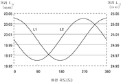
도 8은 회전 각도 θ와 거리 L1 및 L2의 관계를 나타내는 그래프로, 환상 슬릿의 반경이 20mm, 환상 슬릿의 편심량이 40μm인 경우에 있어서의 회전 각도 θ와, 거리 L1 및 L2의 관계를 나타내고 있다. 8 is a graph showing the relationship between the rotation angle θ and the distances L 1 and L 2 , wherein the rotation angle θ and the distances L 1 and L 2 in the case where the radius of the annular slit is 20 mm and the eccentricity of the annular slit are 40 μm. The relationship is shown.
(실시예 1의 신호 처리 장치) (Signal Processing Apparatus of Example 1)
다음으로 회전 각도를 검출하기 위한 신호 처리 장치에 대해서 설명한다. Next, a signal processing apparatus for detecting the rotation angle will be described.
도 9는 본 실시예에 있어서의 광학식 인코더의 신호 처리 장치의 제 1 예를 나타내는 블록도이다. 9 is a block diagram showing a first example of a signal processing apparatus of an optical encoder in the present embodiment.
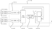
도 9에 나타낸 바와 같이, 신호 처리 장치(170)는 AD 변환 소자(181, 182)와, 제 1 변위 검출 처리부(201)와, 제 2 변위 검출 처리부(202)와, 각도 검출 처리부(210)를 갖는다. As shown in FIG. 9, the
AD 변환 소자(181)는 제 1 환상 슬릿(25A)과 제 1 고정 슬릿(21A)이 겹쳐진 상태에 의해서 생기는 제 1 수광 소자(22A)의 A상 수광부(22AA)와 B상 수광부(22AB)로부터의 위상이 다른 2상의 대략 정현파 신호를 각각 AD 변환한다. AD 변환 소자(182)는 제 2 환상 슬릿(25B)과 제 2 고정 슬릿(21B)이 겹쳐진 상태에 의해서 생기는 제 2 수광 소자(22B)의 A상 수광부(22BA)와 B상 수광부(22BB)로부터의 위상이 다른 2상의 대략 정현파 신호를 각각 AD 변환한다. The
제 1 변위 검출 처리부(201)는 AD 변환 소자(181)에서 디지털화된 2상의 대략 정현파 신호를 기초로, 제 1 환상 슬릿(25A)의 회전축의 반경 방향으로의 변위인 제 1 변위를 산출한다. 제 2 변위 검출 처리부(202)는 AD 변환 소자(182)에서 디지털화된 2상의 대략 정현파 신호를 기초로, 제 2 환상 슬릿(25B)의 회전축의 반경 방향으로의 변위인 제 2 변위를 산출한다. The first displacement
각도 검출 처리부(210)는 제 1 변위 검출 처리부(201)에서 산출한 제 1 변위와 제 2 변위 검출 처리부(202)에서 산출한 제 2 변위를 기초로, 회전 각도를 검출한다. 이와 같이 본 실시예에 따른 광학식 인코더(1)는 제 1 변위 처리부(201) 및 제 2 변위 처리부(202)의 출력 신호로부터 0~360도의 전체 둘레에 걸쳐서 임의의 회전 각도를 검출할 수 있다. The angle
한편, 상기 변위 검출 처리 및 각도 검출 처리부의 알고리즘은 특정한 방식에 구애되지 않는다. 일례로서, 2상의 대략 정현파 신호의 한쪽 신호를 A, 다른쪽 신호를 B로 해서, θ=tan- 1(B/A)를 연산하여, 회전 각도 θ를 연산하는 방식이 있다. 이와 같은 알고리즘을 이하에서는 내삽분할처리라고 한다. On the other hand, the algorithm of the displacement detection processing and the angle detection processing is not limited to a specific method. By way of example, to the one signal of substantially sinusoidal signal, an A, the other signal to the B, θ = tan on the two-there is by computing the 1 (B / A), method of calculating the rotation angle θ. Such an algorithm is hereinafter referred to as interpolation split processing.
다음으로 회전 각도를 검출하기 위한 신호 처리 단계에 대해서 설명한다. Next, a signal processing step for detecting the rotation angle will be described.
도 10는 신호 처리의 단계를 나타내는 흐름도이다. 10 is a flowchart showing the steps of signal processing.
1) 단계 1에서, 제 1 환상 슬릿(25A)과 제 1 고정 슬릿(21A)이 겹쳐진 상태에 의해서 생기는 제 1 수광 소자(22A)의 A상 수광부(22AA)와 B상 수광부(22AB)로부터의 위상이 다른 2상의 대략 정현파 신호를, AD 변환 소자(181)에서 AD 변환하여, 디지털 신호로 한다. 1) In
2) 단계 2에서, 단계 1에서 변환된 2개의 디지털 신호를 기초로, 제 1 변위 검출 처리부(201)에서 거리 L1을 산출한다. 2) In
3) 단계 3에서, 제 2 환상 슬릿(25B)과 제 2 고정 슬릿(21B)이 겹쳐진 상태에 의해서 생기는 제 2 수광 소자(22B)의 A상 수광부(22BA)와 B상 수광부(22BB)로부터의 위상이 다른 2상의 대략 정현파 신호를, AD 변환 소자(182)에서 AD 변환하여, 디지털 신호로 한다. 3) In
4) 단계 4에서, 단계 3에서 변환된 2개의 디지털 신호를 기초로, 제 2 변위 검출 처리부(202)에서 거리 L2을 산출한다. 4) In
5) 단계 5에서, 단계 2과 단계 4에서 획득한 L1과 L2를 기초로, 각도 검출 처리부(210)에서 (1)~(4) 식 등으로부터 회전 각도 θ를 구한다. 5) In
한편, 단계 1과 단계 3은 어느 것부터 먼저 행해도 상관없고, 단계 2과 단계 4도 어느 것부터 먼저 행해도 상관없다. 또한, 동시 병행적으로 처리해도 상관없다. In addition,
다음으로 본 실시예에 있어서의 신호 처리 장치의 다른 예에 대해서 설명한다. Next, another example of the signal processing apparatus in the present embodiment will be described.
도 11은 본 실시예에 있어서의 광학식 인코더의 신호 처리 장치의 제 2 예를 나타내는 블록도로, 제 1 예에서 나타낸 신호 처리 장치에 있어서 제 1 변위 검출 처리부(201)와 제 2 변위 검출 처리부(202)의 공통화를 도모한 예이다. Fig. 11 is a block diagram showing a second example of the signal processing apparatus of the optical encoder in the present embodiment. In the signal processing apparatus shown in the first example, the first displacement
이 예에 따른 신호 처리 장치(170)는 도 11에 나타낸 바와 같이, AD 변환 소자(181, 182)와, 전환 스위치(180)와, 변위 검출 처리부(200)와, 기억부(190)와, 각도 검출 처리부(210)를 갖는다. As shown in FIG. 11, the
변위 검출 처리부(200)는 상기 변위 검출 처리부(201, 202)와 같이 구성할 수 있지만, 이 변위 검출 처리부(200)의 전단에 전환 스위치(180)가 마련되어 있다. 전환 스위치(180)는, 변위 검출 처리부(200)에 AD 변환 소자(181)로부터의 신호를 입력하는 경우와, AD 변환 소자(182)로부터의 신호를 입력하는 경우를 전환한다. 그 결과, 변위 검출 처리부(200)에 입력되는 디지털 신호가 선택된다. Although the displacement
한편, 변위 검출 처리부(200)의 후단에 기억부(190)가 마련되고, 기억부(190)에는 변위 검출 처리부에 AD 변환 소자(181)로부터의 신호를 입력한 경우의 거리 L1의 산출 결과 및 AD 변환 소자(182)로부터의 신호를 입력한 경우의 거리 L2의 산출 결과가 기억된다. On the other hand, a
각도 검출 처리부(210)는 제 1 변위 검출 처리부(201)에서 산출, 또는 일단 기억부(190)에 기억한 제 1 변위와, 제 2 변위 검출 처리부(202)에서 산출, 또는 일단 기억부(190)에 기억한 제 2 변위를 기초로, 내삽 분할 처리를 행함으로써, 회전 각도 θ를 검출한다. The angle
다음으로 회전 각도를 검출하기 위한 신호 처리의 단계에 대해서 설명한다. Next, the steps of signal processing for detecting the rotation angle will be described.
도 12는 신호 처리의 단계를 나타내는 흐름도이다. 12 is a flowchart showing the steps of signal processing.
1) 단계 1에서, 제 1 환상 슬릿(25A)과 제 1 고정 슬릿(21A)이 겹쳐진 상태에 의해서 생기는 제 1 수광 소자(22A)의 A상 수광부(22AA)와 B상 수광부(22AB)로부터의 위상이 다른 2상의 대략 정현파 신호를, AD 변환 소자(181)에서 AD 변환하여, 디지털 신호로 한다. 1) In
2) 단계 2에서, 제 2 환상 슬릿(25B)과 제 2 고정 슬릿(21B)이 겹쳐진 상태에 의해서 생기는 제 2 수광 소자(22B)의 A상 수광부(22BA)와 B상 수광부(22BB)로부터의 위상이 다른 2상의 대략 정현파 신호를, AD 변환 소자(182)에서 AD 변환하여, 디지털 신호로 한다. 2) In
3) 단계 3에서, 상위 제어부(도시 생략)로부터의 전환 신호에 따라, 전환 스위치(180)가 단계 1에서 변환된 2개의 디지털 신호를 변위 검출 처리부(200)의 입력으로서 선택하면, 변위 검출 처리부(200)에서 거리 L1을 산출하여, 기억부(190)에 기억한다. 3) In
4) 단계 4에서, 상위 제어부로부터의 전환 신호에 따라, 전환 스위치(180)가 단계 2에서 변환된 2개의 디지털 신호를 변위 검출 처리부(200)의 입력으로서 선택하면, 변위 검출 처리부(200)에서 거리 L2을 산출하여, 기억부(190)에 기억한다. 4) In
5) 단계 5에서, 단계 3과 단계 4에서 기억한 L1과 L2를 기초로, 각도 검출 처리부(203)에서 (1)~(4) 식 등으로부터 회전 각도 θ를 구한다. 5) In
한편, 단계 1과 단계 2는 어느 것부터 먼저 행해도 상관없고, 동시 병행적으로 처리해도 상관없다. In addition, you may perform
다음으로 본 실시예에 있어서의 신호 처리 장치의 또 다른 예에 대해서 설명한다. Next, another example of the signal processing apparatus according to the present embodiment will be described.
도 13은 본 실시예에 있어서의 광학식 인코더의 신호 처리 장치의 제 3 예를 나타내는 블록도로, 제 1 예에서 나타낸 신호 처리 장치의 변위 검출 처리부(200)와 각도 검출 처리부(210)의 공통화를 도모한 예이다. Fig. 13 is a block diagram showing a third example of the signal processing device of the optical encoder in the present embodiment, in which the displacement
이 예에 따른 신호 처리 장치(170)는 도 13에 나타낸 바와 같이, AD 변환 소자(181, 182)와, 전환 스위치(180)와, 변위 검출 처리부(200)와, 기억부(190)를 갖는다. As shown in FIG. 13, the
이 예에서도 변위 검출 처리부(200)의 전단에 전환 스위치(180)가 마련되어 있다. 한편, 본 예에 따른 전환 스위치(180)는, 변위 검출 처리부에, 제 1 환상 슬릿(25A)과 제 1 고정 슬릿(21A)이 겹쳐진 상태에 의해서 생기는 제 1 수광 소자(22A)의 A상 수광부(22AA)와 B상 수광부(22AB)로부터의 위상이 다른 2상의 대략 정현파 신호를 AD 변환 소자(181)에서 디지털화한 신호를 입력하는 경우와, 제 2 환상 슬릿(25B)과 제 2 고정 슬릿(21B)이 겹쳐진 상태에 의해서 생기는 제 2 수광 소자(22B)의 A상 수광부(22BA)와 B상 수광부(22BB)로부터의 위상이 다른 2상의 대략 정현파 신호를 AD 변환 소자(182)에서 디지털화한 신호를 입력하는 경우와, 앞의 2가지 경우 각각의 산출 결과인 L1과 L2가 입력되는 경우의 3가지 경우를 전환한다. 이로써, 변위 검출 처리부(200)에 입력되는 신호가 선택된다. Also in this example, the
또한, 변위 검출 처리부(200)의 후단에 기억부(190)가 마련되어 있다. 기억부(190)에는, 변위 검출 처리부에, AD 변환 소자(181)에서 디지털화한 신호를 입력한 경우의 거리 L1의 산출 결과와, AD 변환 소자(182)에서 디지털화한 신호를 입력한 경우의 거리 L2의 산출 결과가 기억된다. In addition, the
다음으로 회전 각도를 검출하기 위한 신호 처리의 단계에 대해서 설명한다. Next, the steps of signal processing for detecting the rotation angle will be described.
도 14는 본 실시예에 있어서의 신호 처리의 단계를 나타내는 흐름도이다. 14 is a flowchart showing the steps of signal processing in the present embodiment.
1) 단계 1에서, 제 1 환상 슬릿(25A)과 제 1 고정 슬릿(21A)이 겹쳐진 상태에 의해서 생기는 제 1 수광 소자(22A)의 A상 수광부(22AA)와 B상 수광부(22AB)로부터의 위상이 다른 2상의 대략 정현파 신호를, AD 변환 소자(181)에서 AD 변환하여, 디지털 신호로 한다. 1) In
2) 단계 2에서, 제 2 환상 슬릿(25B)과 제 2 고정 슬릿(21B)이 겹쳐진 상태에 의해서 생기는 제 2 수광 소자(22B)의 A상 수광부(22BA)와 B상 수광부(22BB)로부터의 위상이 다른 2상의 대략 정현파 신호를, AD 변환 소자(182)에서 AD 변환하여, 디지털 신호로 한다. 2) In
3) 단계 3에서, 상위 제어부(도시 생략)로부터의 전환 신호에 따라, 전환 스위치(180)가 단계 1에서 변환된 2개의 디지털 신호를 변위 검출 처리부(200)의 입력을 선택하면, 변위 검출 처리부(200)에서 거리 L1을 산출하여, 기억부(190)에 기억한다. 3) In
4) 단계 4에서, 상위 제어부로부터의 전환 신호에 따라, 전환 스위치(180)가 단계 2에서 변환된 2개의 디지털 신호를 변위 검출 처리부(200)의 입력으로서 선택하면, 변위 검출 처리부(200)에서 거리 L2를 산출하여, 기억부(190)에 기억한다. 4) In
5) 단계 5에서, 상위 제어부로부터의 전환 신호에 따라, 전환 스위치(180)가 단계 3과 단계 4에서 기억한 거리 L1과 거리 L2를 변위 검출 처리부(200)의 입력으로서 선택하면, 변위 검출 처리부(200)가 상기 (1)~(4) 식으로부터 회전 각도 θ를 구한다. 5) In
한편, 단계 1, 단계 2는, 어느 것부터 먼저 행해도 상관없고, 동시 병행적으로 처리해도 상관없다. In addition, you may perform
또한, 특히 제 1 환상 슬릿(25A) 및 제 1 고정 슬릿(21A)의 슬릿 피치와, 제 2 환상 슬릿(25B) 및 제 2 고정 슬릿(21B)의 슬릿 피치를, 각각의 환상 슬릿의 편심량 d1, d2보다 크게 설정함으로써 회전 디스크(13)의 0도부터 360도의 회전으로, 제 1 환상 슬릿(25A)과 제 1 고정 슬릿(21A)의 개구부의 위치 관계 및 제 2 환상 슬릿(25B)과 제 2 고정 슬릿(21B)의 개구부의 위치 관계는, 일의적(一義的)으로 정해져서, 환상 슬릿(25)의 변위로부터 회전 각도의 절대치를 산출할 수 있다. 예컨대, 상기 환상 슬릿(25)의 회전축에 대한 편심량을 40μm이라고 하면, 상기 환상 슬릿(25)과 제 1 고정 슬릿(21A) 및 제 2 고정 슬릿(21B)의 슬릿 피치를 50μm으로 하면 된다. Moreover, especially the slit pitch of the 1st annular slit 25A and the 1st fixed slit 21A, and the slit pitch of the 2nd
이와 같이, 본 실시예에서는 회전 디스크의 중심에 대해 편심된 복수의 동심원 슬릿을 갖는 제 1 환상 슬릿과, 제 1 환상 슬릿과는 다른 방향으로 편심된 복수의 동심원 슬릿을 갖는 제 2 환상 슬릿을 회전 디스크 상에 형성했기 때문에, 0~360도의 전체 둘레에 걸쳐서 임의의 회전 각도를 검출할 수 있음과 아울러, 제 1 검출부와 제 2 검출부를 근접한 위치에 배치할 수 있기 때문에 소형의 광학식 인코더를 실현할 수 있다.
As described above, in this embodiment, the first annular slit having a plurality of concentric slit eccentric with respect to the center of the rotating disk and the second annular slit having a plurality of concentric slit eccentric in a direction different from the first annular slit are rotated. Since it is formed on the disk, it can detect arbitrary rotation angles over the whole circumference of 0-360 degree, and can arrange | position a 1st detection part and a 2nd detection part in the adjacent position, and can realize a compact optical encoder. have.
<실시예 2><Example 2>
(실시예 2의 구성)(Configuration of Example 2)
도 15는 본 발명의 실시예 2를 나타내는 광학식 인코더의 측면도이다. Fig. 15 is a side view of an optical
실시예 1과의 주요 차이점은 3격자 원리를 적용한 반사형의 광학계의 구성으로 되어 있다는 점이다. 한편, 본 실시예에 따른 신호 처리부(17)는 상기 실시예 1이나 하기 실시예 3과 같이 구성 가능하기 때문에, 설명의 편의상 생략한다. The main difference from the first embodiment is that the reflective optical system is applied to the three-lattice principle. In addition, since the
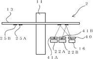
본 실시예에 따른 광학식 인코더(2)에서는, 회전 디스크(13)의 제 1 수광 소자(22A) 및 제 2 수광 소자(22B)와 동일면 측에 광원(16)이 배치되고, 광원(16)의 광로 상에 광원 슬릿(40)이 배치되며, 제 1 고정 슬릿(21A) 및 제 2 고정 슬릿(21B) 대신 제 1 인덱스 슬릿(41A)과 제 2 인덱스 슬릿(41B)(3격자 광학계의 경우의 1개의 고정슬릿의 일 예)이 배치된다. In the
즉, 광원 슬릿(40)은 광원(16) 앞에 설치되고, 광원 슬릿(40)과 제 1 환상 슬릿(25A)과 제 1 인덱스 슬릿(41A)으로 3격자가 형성되어 있다. 마찬가지로, 광원 슬릿(40)과 제 2 환상 슬릿(25B)과 제 2 인덱스 슬릿(41B)으로도 3격자가 형성되어 있다. That is, the light source slit 40 is provided in front of the
상술한 바와 같이, 본 발명에 따른 각 실시예에서는, 환상 슬릿에 복수의 등피치로 형성된 동심원 슬릿 패턴을 이용하고 있기 때문에, 등피치로 형성한 고정 슬릿과 등피치로 형성한 광원 슬릿을 조합하여, 3격자 광학계를 적용한 광학식 인코더를 실현할 수 있다. As described above, in each embodiment according to the present invention, since the concentric circular slit pattern formed of a plurality of equal pitches is used for the annular slit, a three-lattice grid is formed by combining a fixed slit formed at the same pitch and a light source slit formed at the same pitch. The optical encoder to which the optical system is applied can be realized.
구체적인 구성을 도 16 및 도 17의 사시도를 이용해서 설명한다. The specific structure is demonstrated using the perspective view of FIG. 16 and FIG.
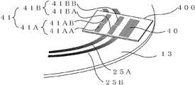
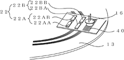
도 16은 회전 디스크(13)와 광원 슬릿(40) 및 인덱스 슬릿(41)의 배치를 나타낸 것이다. 도 17은 도 16에 광원(16)과 수광 소자(22)를 더해서 표시한 것이다. FIG. 16 shows the arrangement of the
제 1 환상 슬릿 변위의 방향을 검출하기 위해서, 제 1 인덱스 슬릿(41A)은 도 16과 같이 위상을 어긋나게 한 A상 슬릿(41AA)과 B상 슬릿(41AB)으로 구성되어 있다. 이에 대응해서, 제 1 수광 소자(22A)도, 도 17과 마찬가지로 A상 수광부(22AA)와 B상 수광부(22AB)로 분할되어 있다. 마찬가지로, 제 2 인덱스 슬릿(41B)도, 위상을 어긋나게 한 A상 슬릿(41BA)과 B상 슬릿(41BB)으로 형성되고, 제 2 수광 소자(22B)도 A상 수광부(22BA)와 B상 수광부(22BB)로 분할되어 있다. In order to detect the direction of the first annular slit displacement, the first index slit 41A is composed of an A-phase slit 41AA and a B-phase slit 41AB in which phases are shifted as shown in FIG. 16. Correspondingly, the first light receiving element 22A is also divided into an A-phase light receiving portion 22AA and a B-phase light receiving portion 22AB similarly to FIG. 17. Similarly, the second index slit 41B is also formed of the A phase slit 41BA and the B phase slit 41BB which are out of phase, and the second light receiving element 22B is also the A phase light receiving portion 22BA and the B phase light receiving portion. It is divided into 22BB.
한편, 광원 슬릿(40)과, 제 1 인덱스 슬릿의 A상 슬릿(41AA)과 B상 슬릿(41AB)과, 제 2 인덱스 슬릿의 A상 슬릿(41BA)과 B상 슬릿(41BB)은 400으로 표시한 동일 기판 상에 형성하는 것이 가능하다. 또한, 인덱스 슬릿을 광원 슬릿(40)과 동일 기판 상에 형성하지 않고, 환상 슬릿과 동일 피치의 슬릿이 형성된 슬릿 패턴 형상의 수광 소자를 이용함으로써, 인덱스 슬릿을 생략할 수도 있다. On the other hand, the light source slit 40, the A phase slit 41AA and the B phase slit 41AB of the first index slit, the A phase slit 41BA and the B phase slit 41BB of the second index slit are 400, respectively. It is possible to form on the same substrate shown. In addition, the index slit can be omitted by using a slit pattern light-receiving element in which the index slit is not formed on the same substrate as the light source slit 40, and the slit having the same pitch as the annular slit is formed.
또한, 제 1 환상 슬릿(25A)과 제 2 환상 슬릿(25B)에서는, 광원(16)으로부터의 광이 조사되어 검출에 기여하는 부분이, 국소적으로 직선으로 보이기 때문에, 광원 슬릿과 인덱스 슬릿의 형상은 함께 리니어 형상으로 작성할 수 있다.
In addition, in the first annular slit 25A and the second
(실시예 2의 동작)(Operation of Example 2)
이어서, 동작에 대해서 설명한다. Next, the operation will be described.
3격자 원리에 의해, 광원(16)으로부터 조사되어 광원 슬릿(40)을 통과하여 제 1 환상 슬릿(25A)에서 반사한 광에 의해 제 1 인덱스 슬릿(41A) 상에 간섭 줄무늬가 생긴다. By the three-lattice principle, interference fringes are generated on the first index slit 41A by the light irradiated from the
제 1 환상 슬릿(25A)은 회전 디스크(13)의 중심(103)에 대해 편심되게 형성되어 있기 때문에, 회전축(11)이 회전하면, 광원(16)으로부터의 광이 조사되는 위치에 있는 제 1 환상 슬릿(25A)의 부분과 회전축(11)의 회전 중심(100)의 사이의 거리 L1은 회전축(11)의 회전 각도 θ에 따라 변화된다. 이 때문에, 인덱스 슬릿(41A) 상에 생기는 간섭 줄무늬의 상(像)도 추종해서 변화된다. 따라서, 이 간섭 줄무늬의 상과 제 1 인덱스 슬릿(41A)의 개구부의 상관을 제 1 수광 소자(22A)에서 검출함으로써 거리 L1을 검출할 수 있다. 마찬가지로, 광원(16)으로부터의 광이 조사되는 위치에 있는 제 2 환상 슬릿(25B)의 거리 L2도 검출할 수 있다. 이 거리 L1와 거리 L2의 값을 이용함으로써 실시예 1과 같이 0~360도의 전체 둘레에 걸쳐서 임의의 회전 각도를 검출할 수 있다. Since the first annular slit 25A is formed to be eccentric with respect to the
이와 같이, 본 실시예에서는 3격자 원리를 적용한 광학계를 이용하고 있기 때문에, 실시예 1의 효과에 더해서, 회전 디스크와 고정 슬릿 사이의 갭 변동에 강한 광학식 인코더를 실현할 수 있다. As described above, since the optical system adopting the three-lattice principle is used in the present embodiment, in addition to the effect of the first embodiment, an optical encoder that is resistant to the gap variation between the rotating disk and the fixed slit can be realized.
실시예 1에서는 회전 디스크(13)의 중심(103)이 회전축(11)의 회전 중심(100)과 일치하도록 정밀도 좋게 부착된 경우에 대해서 설명했지만, 회전 디스크(13)의 부착 정밀도가 나쁘면 회전 디스크(13)의 중심(103)은 회전축(11)의 회전 중심(100)으로부터 어긋나버리는 경우가 있다. 실시예 3을 나타내기 전에 우선, 회전 디스크(13)의 부착 정밀도가 나쁜 경우의 문제점에 대해서 도 18을 이용해서 설명한다. In Example 1, the case where the
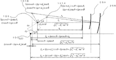
도 18은 회전 디스크의 중심이 회전 중심에 대해 어긋나게 부착된 경우의 회전 디스크의 상태를 나타내는 평면도이다. 이 도 18에서는 회전 디스크(13)의 중심(103)과 회전축(11)의 회전 중심(100)이 X 방향으로 Δx, Y 방향으로 Δy 어긋나게 부착된 경우의 상태를 나타내고 있다. 또한, 도 19는 도 18의 위치로부터 회전 각도 θ만큼 회전한 경우의 회전 디스크의 상태를 나타내는 평면도, 도 20은 도 19의 주요부 확대도이다. 18 is a plan view showing a state of the rotating disk when the center of the rotating disk is attached to the rotating center. In this FIG. 18, the state in the case where the
도 20에 있어서, 회전 중심(100)으로부터 제 1 고정 슬릿(21A)에 대응하는 검출부의 환상 슬릿(25A) 사이의 거리 L1은, 도면과 같이 In FIG. 20, the distance L 1 between the
![]()
![]()
……(5)… … (5)
로 표현된다. Lt; / RTI >
d1이 r1에 비해서, 충분히 작을 때는 When d 1 is small enough for r 1
![]()
![]()
로 근사된다. Is approximated.
마찬가지로, 회전 중심(100)으로부터 제 2 고정 슬릿(21B)에 대응하는 검출부의 환상 슬릿(25B) 사이의 거리 L2는 도면과 마찬가지로 Similarly, the distance L 2 between the
![]()
![]()
……(7)… … (7)
로 표현된다. Lt; / RTI >
d2가 r2에 비해서, 충분히 작을 때는 When d 2 is small enough compared to r 2
![]()
![]()
로 근사된다. Is approximated.
(6) 식을 (2) 식과 비교하면, 회전 디스크(13)의 중심(103)과 회전축(11)의 회전 중심(100)의 X 방향으로의 어긋남 Δx에 의해서 L1의 진폭이 변화되고, Y 방향으로의 어긋남 Δy에 의해서 L1의 위상이 변화된다는 것을 알 수 있다. 마찬가지로, (8) 식을 (4) 식과 비교하면, 회전 디스크(13)의 중심(103)과 회전축(11)의 회전 중심(100)의 X 방향으로의 어긋남 Δx에 의해서 L2의 진폭이 변화되고, Y 방향으로의 어긋남 Δy에 의해서 L2의 위상이 변화된다는 것을 알 수 있다. When the equation (6) is compared with the equation (2), the amplitude of L 1 is changed by the shift Δx of the
예컨대, Δx=-d1, Δy=0인 경우, For example, when Δx = −d 1 and Δy = 0,
![]()
![]()
이 되어서, 회전 디스크(13)가 회전해도, 거리 L1은 변화되지 않게 되어 버린다. Thus, even if the
이와 같이, 실시예 1의 인코더에 있어서는 회전 디스크(13)의 부착 정밀도가 나쁘면, 회전 디스크(13)의 중심(103)과 회전축(11)의 회전 중심(100)이 어긋나 버려서, 제 1 고정 슬릿(21A)에 대응하는 검출부의 환상 슬릿(25A) 사이의 거리 L1 또는 환상 슬릿(25B) 사이의 거리 L2을 정확하게 검출할 수 없는 경우가 있었다.
Thus, in the encoder of Example 1, when the attachment precision of the
<실시예 3><Example 3>
(실시예 3의 구성)(Configuration of Example 3)
도 21은 본 발명의 실시예 3을 나타내는 광학식 인코더의 측면도, 도 22는 평면도이다. 본 실시예는 상기한 문제를 해결할 수 있는 것이다. 한편, 도 22의 평면도는 도 21을 종이면의 아래측으로부터 본 도면이다. 실시예 1의 인코더와 동일한 구성 부품은 동일 번호를 붙이고 설명을 생략한다. 21 is a side view of an optical encoder according to a third embodiment of the present invention, and FIG. 22 is a plan view. This embodiment can solve the above problem. On the other hand, the top view of FIG. 22 is a figure which looked at FIG. 21 from the lower side of the paper surface. The same components as those of the encoder of the first embodiment are denoted by the same numerals and description thereof is omitted.
본 실시예에 따른 광학식 인코더(3)는 도 21에 나타낸 바와 같이, 실시예 1에 따른 인코더(1)의 구성에 더해서, 제 3 환상 슬릿(25C)과, 제 3 검출부(12C)를 갖는다. As shown in FIG. 21, the
제 3 환상 슬릿(25C)은 제 1 환상 슬릿(25A) 및 제 2 환상 슬릿(25B)과 같이 복수의 동심원 슬릿 패턴을 갖는다. 한편, 이 제 3 환상 슬릿(25C)은 동심원의 중심이 회전 디스크의 중심이 되도록 형성된다. 제 3 검출부(12C)는 제 3 환상 슬릿(25C)에 대응하여, 고정 부재(도시 생략)에 마련된다. The third
제 3 검출부(12C)는 도 21에 나타낸 바와 같이, 제 3 고정 슬릿(21C)과, 제 3 수광 소자(22C)를 갖는다. As shown in FIG. 21, the third detection unit 12C includes a third fixed slit 21C and a third
즉, 본 실시예가 실시예 1과 다른 점은 회전 디스크 상에 제 3 환상 슬릿을 형성하고, 이에 대응하는 광학계인 제 3 고정 슬릿 및 제 3 수광 소자가 부가된 점이다. That is, the present embodiment differs from the first embodiment in that a third annular slit is formed on the rotating disk, and a third fixed slit and a third light receiving element, which are optical systems corresponding thereto, are added.
도 4 및 도 5에 나타낸 제 1 고정 슬릿(21A), 제 1 수광 소자(22A) 및 제 2 고정 슬릿(21B), 제 2 수광 소자(2B)와 같이, 제 3 고정 슬릿(21C)은 서로 위상이 다른 A상의 슬릿군(21CA)과, B상의 슬릿군(21CB)이 형성되고, 제 3 수광 소자(22C)는 A상 수광부(22CA)와 B상 수광부(22CB)의 2개로 분할되어 있다. Like the first fixed slit 21A, the first light receiving element 22A, the second fixed slit 21B, and the second light receiving element 2B shown in FIGS. 4 and 5, the third fixed slit 21C is mutually different. A phase slit group 21CA and phase B slit group 21CB are formed, and the 3rd
여기서, 제 3 고정 슬릿(21C)과 제 3 수광 소자(22C)는 일체적으로 구성해도 상관없다. 또한, 광원(16)은 제 1 환상 슬릿(25A)용과, 제 2 환상 슬릿(25B)용과, 제 3 환상 슬릿(25C)용으로, 각각 별도의 소자를 이용해도 상관없다. Here, the third fixed slit 21C and the third
도 23은 환상 슬릿의 패턴예를 나타내는 평면도로, 회전 디스크(13) 상에 형성된 제 1 환상 슬릿(25A)과 제 2 환상 슬릿(25B)과 제 3 환상 슬릿(25C)의 형성 패턴예를 나타낸다. FIG. 23 is a plan view showing a pattern example of the annular slit, and shows an example of the formation pattern of the first annular slit 25A, the second
제 1 환상 슬릿(25A)은 회전 디스크(13)의 중심(103)에 대해서 X축 방향으로 거리 d1만큼 편심된 점(101A)을 중심으로 한 반경 r1의 원을 중앙으로 해서 Δr1씩 반경이 다른 복수(도면에서는 5개)의 동심원 슬릿으로 형성되어 있다. 제 2 환상 슬릿(25B)은 회전 디스크(13)의 중심(103)에 대해서 Y축 방향으로 거리 d2만큼 편심된 점(101B)을 중심으로 한 반경 r2의 원을 중앙으로 해서 Δr2씩 반경이 다른 복수(도면에서는 5개)의 동심원 슬릿으로 형성되어 있다. 제 3 환상 슬릿(25C)은 회전 디스크(13)의 중심(103)을 중심으로 한 반경 r0인 원을 중앙으로 해서 Δr0씩 반경이 다른 복수(도면에서는 5개)의 동심원 슬릿으로 형성되어 있다. The first annular slit 25A has a circle of radius r 1 centered on a
여기서, 도 18에 나타낸 바와 같이 부착 오차에 의해, 회전 디스크(13)의 중심(103)과 회전축(11)의 회전 중심(100)이 X 방향으로 Δx, Y 방향으로 Δy 어긋나서 회전 디스크(13)가 부착된 경우를 생각한다. Here, as shown in FIG. 18, due to the attachment error, the
도 24는 회전 디스크의 중심이 회전 중심에 대해 어긋나게 부착된 경우의 회전 디스크의 상태를 나타내는 평면도이고, 도 25는 도 24의 상태로부터 회전 디스크가 회전 각도 θ만큼 회전했을 때의 상태를 나타내는 평면도이다. 또한, 도 26은 도 25의 주요부 확대도이다. FIG. 24 is a plan view showing a state of the rotating disk when the center of the rotating disk is attached to the rotation center displaced, and FIG. 25 is a plan view showing the state when the rotating disk is rotated by the rotation angle θ from the state of FIG. . 26 is an enlarged view of the main part of FIG.
상기에서 설명한 바와 같이 회전 중심(100)으로부터 제 1 고정 슬릿(21A)에 대응하는 검출부의 환상 슬릿(25A) 사이의 거리 L1은 (6) 식, 회전 중심(100)으로부터 제 2 고정 슬릿(21B)에 대응하는 검출부의 환상 슬릿(25B) 사이의 거리 L2은 (8) 식으로 표현된다. As described above, the distance L 1 between the annular slit 25A of the detection unit corresponding to the first fixed slit 21A from the
한편, 도 26으로부터 회전 중심(100)으로부터 제 3 고정 슬릿(21C)에 대응하는 검출부의 환상 슬릿(25C)의 사이의 거리 L0은 On the other hand, the distance L 0 between the
![]()
![]()
로 표현된다. Lt; / RTI >
(6)-(10)로부터From (6)-(10)
![]()
![]()
(8)-(10)로부터From (8)-(10)
![]()
![]()
가 되는 관계가 유도된다. A relationship is derived.
상기 (11) 식, (12) 식 중에는 회전 디스크(13)의 중심(103)과 회전축(11)의 회전 중심(100)의 어긋남에 의한 Δx와 Δy의 항이 소거되어 있다. 이와 같이, L1-L0과, L2-L0의 값은 부착 오차에 관계없이 0~360도의 회전 각도에 대해서, 위상이 다른 정현파상의 변화를 나타낸다. 따라서, 3개의 환상 슬릿으로부터 획득된 L1-L0과, L2-L0의 값을 이용함으로써 회전 각도와의 관계를 일대일로 대응시킬 수 있어 0~360도의 전체 둘레에 걸쳐서 임의의 회전 각도를 검출할 수 있다. In the formulas (11) and (12), the terms Δx and Δy due to the misalignment between the
한편, 이 거리 L1의 값은 제 1 환상 슬릿(25A)과 제 1 고정 슬릿(21A)이 겹쳐진 상태에 의해서 생기는 제 1 수광 소자(22A)의 A상 수광부(22AA)와 B상 수광부(22AB)에서의 2상의 신호를 기초로, 내삽 신호 처리를 행함으로써 산출할 수 있다. 또한, 거리 L2의 값은 제 2 환상 슬릿(25B)과 제 2 고정 슬릿(21B)이 겹쳐진 상태에 의해서 생기는 제 2 수광 소자(22B)의 A상 수광부(22BA)와 B상 수광부(22BB)에서의 2상의 신호를 기초로, 내삽 신호 처리를 행함으로써 산출할 수 있다. On the other hand, the value of this distance L 1 is the A phase light receiving part 22AA and the B phase light receiving part 22AB of the first light receiving element 22A caused by the state where the first annular slit 25A and the first fixed slit 21A overlap. Based on the two-phase signal in ()), it can calculate by performing an interpolation signal process. Further, the value of the distance L 2 is the A phase light receiving portion 22BA and the B phase light receiving portion 22BB of the second light receiving element 22B caused by the state where the second
또한, 거리 L0의 값은 제 3 환상 슬릿(25C)과 제 3 고정 슬릿(21C)이 겹쳐진 상태에 의해서 생기는 제 3 수광 소자(22C)의 A상 수광부(22CA)와 B상 수광부(22CB)에서의 2상의 신호를 기초로, 내삽 신호 처리를 행함으로써 산출할 수 있다. Further, the value of the distance L 0 is the A phase light receiving portion 22CA and the B phase light receiving portion 22CB of the third
획득된 거리 L1, 거리 L2, 거리 L0의 신호를 기초로, L1-L0, L2-L0의 연산을 행하고, 이들 2개의 신호 L1-L0, L2-L0을 기초로, 내삽 신호 처리를 더 이용함으로써, 회전 각도 θ를 산출할 수 있다.
On the basis of the signal of the obtained distances L 1, the distance L 2, the distance L 0, L 1 -L 0, L 2 performs the operation of -L 0, the two
(실시예 3의 신호 처리부) (Signal Processing Unit of Example 3)
다음으로 회전 각도를 검출하기 위한 신호 처리 장치에 대해서 설명한다. Next, a signal processing apparatus for detecting the rotation angle will be described.
도 27은 본 실시예에 있어서의 광학식 인코더의 신호 처리 장치의 제 1 예를 나타내는 블록도이다. Fig. 27 is a block diagram showing a first example of the signal processing device of the optical encoder in the present embodiment.
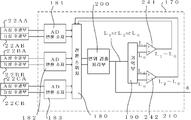
도 27에 나타낸 바와 같이, 신호 처리 장치(170)는 AD 변환 소자(181)~AD 변환 소자(183)와, 제 1 ~제 3 변위 검출 처리부(201~203)와, 감산기(241, 242)와, 각도 검출 처리부(210)를 갖는다. As shown in FIG. 27, the
상기 실시예 1과 같이, AD 변환 소자(181, 182)는 각각 제 1 수광 소자(22A) 및 제 2 수광 소자(22B)로부터의 2상의 대략 정현파 신호를 AD 변환한다. 또한, 제 1 변위 검출 처리부(201)는 AD 변환 소자(181)에서 디지털화된 2상의 대략 정현파 신호를 기초로, 제 1 환상 슬릿(25A)의 회전축의 반경 방향으로의 변위인 제 1 변위(거리 L1)를 산출한다. 제 2 변위 검출 처리부(202)는 AD 변환 소자(182)에서 디지털화된 2상의 대략 정현파 신호를 기초로, 제 2 환상 슬릿(25B)의 회전축의 반경 방향으로의 변위인 제 2 변위(거리 L2)를 산출한다. As in the first embodiment, the
한편, AD 변환 소자(183)는 제 3 환상 슬릿(25C)과 제 3 고정 슬릿(21C)이 겹쳐진 상태에 의해서 생기는 제 3 수광 소자(22C)의 A상 수광부(22CA)와 B상 수광부(22CB)로부터의 위상이 다른 2상의 대략 정현파 신호를 각각 아날로그·디지털 변환한다. On the other hand, the
제 3 변위 검출 처리부(203)는 AD 변환 소자(183)에서 디지털화된 2상의 대략 정현파 신호를 기초로, 내삽 분할 처리를 행함으로써 거리 L0을 산출한다. The third displacement
감산기(241)는 제 1 변위 검출 처리부(201)에서 산출한 거리 L1과 제 3 변위 검출 처리부(203)에서 산출한 거리 L0과의 차 L1-L0을 구한다. 한편, 감산기(242)는 제 2 변위 검출 처리부(202)에서 산출한 거리 L2과 제 3 변위 검출 처리부(203)에서 산출한 L0과의 차 L2-L0을 구한다. 그리고, 각도 검출 처리부(210)는 차 L1-L0과 차 L2-L0을 기초로, (11) 및 (12) 식으로부터 회전 각도 θ를 검출한다. The
한편, 상기 변위 검출 처리 및 각도 검출 처리부의 알고리즘은 특정한 방식에 구애되지 않는다. 간단한 일례로서, 한쪽 신호를 A, 다른쪽 신호를 B로 해서, θ=tan- 1(B/A)를 연산하여, 회전 각도 θ를 연산하는 방식도 취할 수 있다. On the other hand, the algorithm of the displacement detection processing and the angle detection processing is not limited to a specific method. As a simple example, by the one signal A, the other signal to the B, θ = tan - by calculating a 1 (B / A), may also take the way of calculating the angle of rotation θ.
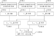
회전 각도를 검출하기 위한 신호 처리의 흐름을 도 28에 나타낸다. 28 shows a flow of signal processing for detecting the rotation angle.
1) 단계 1에서, 제 1 환상 슬릿(25A)과 제 1 고정 슬릿(21A)이 겹쳐진 상태에 의해서 생기는 제 1 수광 소자(22A)의 A상 수광부(22AA)와 B상 수광부(22AB)로부터의 위상이 다른 2상의 대략 정현파 신호를, AD 변환 소자(181)에서 AD 변환하여, 디지털 신호로 한다. 1) In
2) 단계 2에서, 단계 1에서 변환된 2개의 디지털 신호를 기초로, 제 1 변위 검출 처리부(201)에서 거리 L1을 산출한다. 2) In
3) 단계 3에서, 제 2 환상 슬릿(25B)과 제 2 고정 슬릿(21B)이 겹쳐진 상태에 의해서 생기는 제 2 수광 소자(22B)의 A상 수광부(22BA)와 B상 수광부(22BB)로부터의 위상이 다른 2상의 대략 정현파 신호를 AD 변환 소자(182)에서 AD 변환하여, 디지털 신호로 한다. 3) In
4) 단계 4에서, 단계 3에서 변환된 2개의 디지털 신호를 기초로, 제 2 변위 검출 처리부(202)에서 거리 L2을 산출한다. 4) In
5) 단계 5에서, 제 3 환상 슬릿(25C)과 제 3 고정 슬릿(21C)이 겹쳐진 상태에 의해서 생기는 제 3 수광 소자(22C)의 A상 수광부(22CA)와 B상 수광부(22CB)로부터의 위상이 다른 2상의 대략 정현파 신호를 AD 변환 소자(183)에서 AD 변환하여, 디지털 신호로 한다. 5) In
6) 단계 6에서, 단계 5에서 변환된 2개의 디지털 신호를 기초로, 제 3 변위 검출 처리부(203)에서 거리 L0을 산출한다. 6) In
7) 단계 7에서, 단계 2 및 단계 6에서 획득된 거리 L1, 거리 L0로부터, 감산기(241)에서 차 L1-L0을 연산한다. 7) In
8) 단계 8에서, 단계 4 및 단계 6에서 획득된 거리 L2 , 거리 L0로부터, 감산기(242)에서 차 L2-L0을 연산한다. 8) In
9) 단계 9에서, 단계 7 및 단계 8에서 획득된 차(L1-L0)와 차(L2-L0)를 기초로, (11) 및 (12) 식으로부터 각도 검출 처리부(210)에서 회전 각도 θ를 구한다. 9) In step 9, based on the difference (L 1 -L 0 ) and difference (L 2 -L 0 ) obtained in
한편, 단계 1, 2과 단계 3, 4과 단계 5, 6은 어느 것부터 먼저 실시되어도 상관없고, 동시 병행적으로 처리해도 상관없다. In addition,
다음으로 본 실시예에 있어서의 신호 처리 장치의 다른 예에 대해서 설명한다. Next, another example of the signal processing apparatus in the present embodiment will be described.
도 29는 본 실시예에 있어서의 광학식 인코더의 신호 처리 장치의 제 2 예를 나타내는 블록도로, 제 1 예에서 나타낸 신호 처리 장치의 변위 검출 처리부의 공통화를 도모한 예이다. 한편, 이 예에서 신호 처리 장치는 도 11 및 도 12에서 설명한 구성과 같이 구성된다. Fig. 29 is a block diagram showing a second example of the signal processing apparatus of the optical encoder in the present embodiment, and is an example in which the displacement detection processing unit of the signal processing apparatus shown in the first example is in common. On the other hand, in this example, the signal processing apparatus is configured as in the configuration described with reference to Figs.
도 29에 나타낸 바와 같이, 신호 처리 장치(170)는 AD 변환 소자(181)~AD 변환 소자(183)와, 변위 검출 처리부(200)와, 전환 스위치(180)와, 기억부(190)와, 감산기(241, 242)와, 각도 검출 처리부(210)를 갖는다. As shown in FIG. 29, the
변위 검출 처리부(200)의 전단에 전환 스위치(180)가 마련되어 있다. 이 전환 스위치(180)는 변위 검출 처리부(200)에, AD 변환 소자(181)로부터의 신호를 입력하는 경우와, AD 변환 소자(182)로부터의 신호를 입력하는 경우와, AD 변환 소자(183)로부터의 신호를 입력하는 경우를 전환한다. 이로써, 변위 검출 처리부(200)에 입력되는 신호가 선택된다. The
변위 검출 처리부(200)의 후단에 기억부(190)가 마련되어 있다. 기억부(190)에는, 변위 검출 처리부에 AD 변환 소자(181)에서 디지털화한 신호를 입력한 경우의 L1의 산출 결과, AD 변환 소자(182)에서 디지털화한 신호를 입력한 경우의 L2의 산출 결과, AD 변환 소자(183)에서 디지털화한 신호를 입력한 경우의 L0의 산출 결과가 기억된다. The
감산기(241)는 기억부(190)에 기억한 거리 L1과 기억부(190)에 기억한 거리 L0과의 차 L1-L0을 구한다. 감산기(242)는 기억부(190)에 기억한 거리 L2과 기억부(190)에 기억한 거리 L0과의 차 L2-L0을 구한다. 그리고, 각도 검출 처리부(210)는 차 L1-L0과 차 L2-L0을 기초로 회전 각도를 검출한다. The
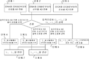
회전 각도를 검출하기 위한 신호 처리의 흐름을 도 30에 나타낸다. 30 shows a flow of signal processing for detecting the rotation angle.
1) 단계 1에서, 제 1 환상 슬릿(25A)과 제 1 고정 슬릿(21A)이 겹쳐진 상태에 의해서 생기는 제 1 수광 소자(22A)의 A상 수광부(22AA)와 B상 수광부(22AB)로부터의 위상이 다른 2상의 대략 정현파 신호를, AD 변환 소자(181)에서 AD 변환하여, 디지털 신호로 한다. 1) In
2) 단계 2에서, 제 2 환상 슬릿(25B)과 제 2 고정 슬릿(21B)이 겹쳐진 상태에 의해서 생기는 제 2 수광 소자(22B)의 A상 수광부(22BA)와 B상 수광부(22BB)로부터의 위상이 다른 2상의 대략 정현파 신호를, AD 변환 소자(182)에서 AD 변환하여, 디지털 신호로 한다. 2) In
3) 단계 3에서, 제 3 환상 슬릿(25C)과 제 3 고정 슬릿(21C)이 겹쳐진 상태에 의해서 생기는 제 3 수광 소자(22C)의 A상 수광부(22CA)와 B상 수광부(22CB)로부터의 위상이 다른 2상의 대략 정현파 신호를, AD 변환 소자(183)에서 AD 변환하여, 디지털 신호로 한다. 3) In
4) 단계 4에서, 상위 제어부(도시 생략)로부터의 전환 신호에 따라, 전환 스위치(180)가 단계 1에서 변환된 2개의 디지털 신호를 변위 검출 처리부(200)의 입력으로 선택하면, 변위 검출 처리부(200)에서 거리 L1을 산출하여, 기억부(190)에 기억한다. 4) In
5) 단계 5에서, 상위 제어부로부터의 전환 신호에 따라, 전환 스위치(180)가 단계 2에서 변환된 2개의 디지털 신호를 변위 검출 처리부(200)의 입력으로 선택하면, 변위 검출 처리부(200)에서 거리 L2을 산출하여, 기억부(190)에 기억한다. 5) In
6) 단계 6에서, 상위 제어부로부터의 전환 신호에 따라, 전환 스위치(180)가 단계 3에서 변환된 2개의 디지털 신호를 변위 검출 처리부(200)의 입력으로 선택하면, 변위 검출 처리부(200)에서 거리 L0을 산출하여, 기억부(190)에 기억한다. 6) In
7) 단계 7에서, 단계 4 및 단계 6에서 기록한 거리 L1, 거리 L0로부터, 감산기(241)에서 차 L1-L0을 연산한다. 7) In
8) 단계 8에서, 단계 5 및 단계 6에서 기록한 거리 L2, 거리 L0로부터, 감산기(242)에서 차 L2-L0을 연산한다. 8) In
9) 단계 9에서, 변위 검출 처리부(210)가, 상위로부터의 전환 신호에 따라, 전환 스위치(180)가 단계 7과 단계 8에서 연산한 차(L1-L0)와 차(L2-L0)를 기초로, (11) 및 (12) 식으로부터 회전 각도 θ를 구한다. 9) In step 9, the displacement
한편, 단계 1~3은 어느 것이 먼저 실시되어도 상관없고, 동시 병행적으로 처리되어도 상관없다. On the other hand, any of
다음으로 본 실시예에 있어서의 신호 처리 장치의 또 다른 예에 대해서 설명한다. Next, another example of the signal processing apparatus according to the present embodiment will be described.
도 31은 본 실시예에 있어서의 광학식 인코더의 신호 처리 장치의 제 3 예를 나타내는 블록도로, 제 1 예로 나타낸 신호 처리 장치의 변위 검출 처리부와 각도 검출 처리부의 공통화를 도모한 예이다. 한편, 이 예에서 신호 처리 장치는 도 13 및 도 14에서 설명한 구성과 마찬가지로 구성된다. FIG. 31 is a block diagram showing a third example of the signal processing apparatus of the optical encoder in the present embodiment, which is an example in which the displacement detection processing unit and the angle detection processing unit of the signal processing apparatus shown in the first example are in common. In this example, the signal processing apparatus is configured similarly to the configuration described with reference to FIGS. 13 and 14.
도 31에 나타낸 바와 같이, 신호 처리 장치(170)는 AD 변환 소자(181)~AD 변환 소자(183)와, 전환 스위치(180)와, 변위 검출 처리부(200)와, 기억부(190)와, 감산기(241, 242)를 갖는다. As shown in FIG. 31, the
변위 검출 처리부(200)의 전단에 전환 스위치(180)가 마련되어 있다. 전환 스위치(180)는 변위 검출 처리부에, AD 변환 소자(181)로부터의 신호를 입력하는 경우와, AD 변환 소자(182)로부터의 신호를 입력하는 경우와, AD 변환 소자(183)로부터의 신호를 입력하는 경우와, 앞의 3가지 경우의 산출 결과의 차인 L1-L0과 L2-L0이 입력되는 경우의 4가지 경우를 전환한다. 이로써, 변위 검출 처리부(200)에 입력되는 신호가 선택된다. The
변위 검출 처리부(200)의 후단에 기억부(190)가 마련되어 있다. 기억부(190)에는, 변위 검출 처리부에 AD 변환 소자(181)에서 디지털화한 신호를 입력한 경우의 거리 L1의 산출 결과와, AD 변환 소자(182)에서 디지털화한 신호를 입력한 경우의 거리 L2의 산출 결과와, AD 변환 소자(183)에서 디지털화한 신호를 입력한 경우의 거리 L0의 산출 결과가 기억된다. The
다음으로 회전 각도를 검출하기 위한 신호 처리의 단계에 대해서 설명한다. Next, the steps of signal processing for detecting the rotation angle will be described.
도 32는 본 실시예에 있어서의 신호 처리의 단계를 나타내는 흐름도이다. 32 is a flowchart showing the steps of signal processing in the present embodiment.
1) 단계 1에서, 제 1 환상 슬릿(25A)과 제 1 고정 슬릿(21A)이 겹쳐진 상태에 의해서 생기는 제 1 수광 소자(22A)의 A상 수광부(22AA)와 B상 수광부(22AB)로부터의 위상이 다른 2상의 대략 정현파 신호를, AD 변환 소자(181)에서 AD 변환하여, 디지털 신호로 한다. 1) In
2) 단계 2에서, 제 2 환상 슬릿(25B)과 제 2 고정 슬릿(21B)이 겹쳐진 상태에 의해서 생기는 제 2 수광 소자(22B)의 A상 수광부(22BA)와 B상 수광부(22BB)로부터의 위상이 다른 2상의 대략 정현파 신호를, AD 변환 소자(182)에서 AD 변환하여, 디지털 신호로 한다. 2) In
3) 단계 3에서, 제 3 환상 슬릿(25C)과 제 3 고정 슬릿(21C)이 겹쳐진 상태에 의해서 생기는 제 3 수광 소자(22C)의 A상 수광부(22CA)와 B상 수광부(22CB)로부터의 위상이 다른 2상의 대략 정현파 신호를, AD 변환 소자(183)에서 AD 변환하여, 디지털 신호로 한다. 3) In
4) 단계 4에서, 상위 제어부(도시 생략)로부터의 전환 신호에 따라, 전환 스위치(180)가 단계 1에서 변환된 2개의 디지털 신호를 변위 검출 처리부(200)의 입력으로 선택하면, 변위 검출 처리부(200)에서 거리 L1을 산출하여, 기억부(190)에 기억한다. 4) In
5) 단계 5에서, 상위 제어부로부터의 전환 신호에 따라, 전환 스위치(180)가 단계 2에서 변환된 2개의 디지털 신호를 변위 검출 처리부(200)의 입력으로서 선택하면, 변위 검출 처리부(200)에서 거리 L2을 산출하여, 기억부(190)에 기억한다. 5) In
6) 단계 6에서, 상위 제어부로부터의 전환 신호에 따라, 전환 스위치(180)가 단계 3에서 변환된 2개의 디지털 신호를 변위 검출 처리부(200)의 입력으로서 선택하면, 변위 검출 처리부(200)에서 거리 L0을 산출하여, 기억부(190)에 기억한다. 6) In
7) 단계 7에서, 단계 4 및 단계 6에서 기록한 거리 L1, 거리 L0로부터, 감산기(241)에서 차 L1-L0을 연산한다. 7) In
8) 단계 8에서, 단계 5 및 단계 6에서 기록한 거리 L2, 거리 L0로부터, 감산기(242)에서 차 L2-L0을 연산한다. 8) In
9) 단계 9에서, 상위 제어부로부터의 전환 신호에 따라, 전환 스위치(180)가 단계 7과 단계 8에서 연산한 차 L1-L0과 차 L2-L0을 변위 검출 처리부(200)의 입력으로서 선택하면, 이 차 L1-L0과 차 L2-L0에 기초해서, 변위 검출 처리부(200)가 (11) 및 (12) 식으로부터 회전 각도 θ를 구한다. 9) In step 9, according to the switching signal from the upper control unit, the
한편, 단계 1~3는 어느 것부터 먼저 행해도 상관없고, 동시 병행적으로 처리되어도 상관없다. In addition, you may perform steps 1-3 before any and may process simultaneously and concurrently.
상기한 바와 같이, 본 실시예의 발명에 의하면, 회전 디스크의 중심과 회전축의 회전 중심이 어긋나게 부착된 경우에도, 0~360도의 전체 둘레에 걸쳐서 정확하게 회전 각도를 검출할 수 있다.
As described above, according to the invention of the present embodiment, even when the center of the rotating disk and the center of rotation of the rotating shaft are attached to each other, the rotation angle can be accurately detected over the entire circumference of 0 to 360 degrees.
<실시예 4> <Example 4>
도 33은 본 발명의 실시예 4를 나타내는 광학식 인코더의 측면도이다. 33 is a side view of an optical
본 실시예에 따른 광학식 인코더(4)는 도 33에 나타낸 바와 같이, 광원 슬릿(40)을 새롭게 갖는다. 광원 슬릿(40)은 광원(16)의 앞에 설치된 광원 슬릿이다. 광원 슬릿(40)과 제 3 환상 슬릿(25C)과 제 3의 인덱스 슬릿(41C)이 3격자를 형성하고 있다. The
즉, 본 실시예가, 실시예 3과 다른 점은 광원 슬릿(40)을 구비해서 3격자 광학계에 의한 반사형의 광학식 인코더(4)를 구성한 점이다. 또한, 실시예 2와 비교하면 제 3 환상 슬릿과 이에 대응하는 광학계, 제 3 인덱스 슬릿(41C) 및 제 3 수광 소자(22C)를 부가한 구성으로 되어 있다. 한편, 본 실시예에 따른 신호 처리부(17)는 상기 실시예 2, 3과 마찬가지로 구성 가능하기 때문에, 설명의 편의상 생략한다. In other words, the present embodiment differs from the third embodiment in that the light source slit 40 is provided to constitute the reflective
구체적인 구성을 도 34 및 도 35의 사시도를 이용해서 설명한다. The specific structure is demonstrated using the perspective view of FIG. 34 and FIG.
도 34는 본 실시예의 광학식 인코더의 구성을 나타내는 사시도로, 회전 디스크(13)와 광원 슬릿(40) 및 인덱스 슬릿(41)의 배치를 나타낸 것이다. 또한, 도 35는 도 34에 광원(16)과 수광 소자(22)를 더해서 표시한 것이다. Fig. 34 is a perspective view showing the structure of the optical encoder of the present embodiment, showing the arrangement of the
이와 같이, 본 실시예에서는 제 3 환상 슬릿과 이에 대응하는 광학계를 부가함과 아울러 3격자 광학계에 의한 반사형의 광학식을 이용하고 있다. 따라서, 본 실시예에 의하면, 0~360도 전체 둘레에 걸쳐서 정확하게 회전 각도를 검출할 수 있음과 아울러, 갭이 변동해도 안정된 센서 신호를 얻을 수 있는 광학식 인코더(4)를 실현할 수 있다. 또한, 모든 광원, 고정 슬릿, 수광 소자 등의 광학 부품을 1개소에 집약해서 배치하면, 장치를 소형으로 할 수 있다.
As described above, in the present embodiment, the third annular slit and the corresponding optical system are added, and the optical system of the reflection type by the three-lattice optical system is used. Therefore, according to the present embodiment, it is possible to realize the
<실시예 5> <Example 5>
도 36은 본 발명의 실시예 5를 나타내는 광학식 인코더의 측면도, 도 37은 평면도이다. 한편, 도 37의 평면도는 도 36을 종이면의 아래측으로부터 본 도면이다. 실시예 1 등의 인코더와 동일한 구성 부품은 동일 번호를 붙이고 설명을 생략한다. 36 is a side view of an optical encoder according to a fifth embodiment of the present invention, and FIG. 37 is a plan view. On the other hand, the top view of FIG. 37 is a figure which looked at FIG. 36 from the lower side of the paper surface. The same components as those of the encoder of the first embodiment are denoted by the same numerals, and description thereof is omitted.
본 실시예에 따른 광학식 인코더(5)는 도 36에 나타낸 바와 같이, 인크리멘탈 슬릿(35)과, 인크리멘탈용 검출부(14)와, 인크리멘탈용 광원(36)을 갖는다. 인크리멘탈용 검출부(14)는 인크리멘탈용 고정 슬릿(31) 및 인크리멘탈용 수광 소자(32)를 갖는다. As shown in FIG. 36, the
본 실시예가 실시예 1과 다른 점은, 회전 디스크 상에 인크리멘탈 슬릿(35)을 형성하고, 이에 대응하는 광학계인 인크리멘탈 광원(36), 인크리멘탈 수광 소자(32) 및 인크리멘탈 고정 슬릿(31)을 부가한 점이다. The present embodiment differs from the first embodiment in that the
인크리멘탈 슬릿(35)은 회전 중심에 대해 방사상으로 형성된다. 이에 대응하여, 인크리멘탈 검출부(14)의 인크리멘탈용 고정 슬릿(31)은 인크리멘탈 슬릿(35)과 대략 평행하게 되도록 복수의 평행한 슬릿 패턴 또는 회전 중심을 중심으로 한 방사상의 슬릿 패턴을 갖는다. 인크리멘탈 광원(36)은 광원(16)과 같이, 인크리멘탈 슬릿(35)에 광을 조사하고, 인크리멘탈 슬릿(35)을 투과한 광은 인크리멘탈 고정 슬릿(31)에 조사된다. 그리고, 인크리멘탈용 수광 소자(32)는 인크리멘탈 고정 슬릿(31)을 투과한 광을 수광하여, 인크리멘탈 신호를 신호 처리 장치(17)(도시 생략)에 출력한다. 그 결과, 신호 처리 장치(17)는 인크리멘탈 신호를 더 이용하여 회전 각도 θ를 산출한다. 한편, 신호 처리 장치(17)에 의한 인크리멘탈 신호로부터의 회전 각도 θ 산출은 실시예 1~실시예 4에서 설명한 신호 처리를 보통의 인크리멘탈 신호에 의한 처리로 적절하게 변경함으로써 실현 가능하기 때문에, 여기서의 상세한 설명은 생략한다.
도시하지 않지만, 회전각의 절대치 및 회전 방향의 검출을 위해, 인크리멘탈용 고정 슬릿(31)은 서로 위상이 다른 2상의 슬릿군으로 구성되고, 각각의 슬릿군에 대해 인크리멘탈용 수광 소자(32)가 마련되어 있다. 한편, 인크리멘탈용 광원(36)을 상기 광원(16)과는 별도로 설치했지만 소형화하기 위해서 하나의 광원으로 겸용할 수도 있다. Although not shown, in order to detect the absolute value of the rotation angle and the rotation direction, the incremental fixed slit 31 is composed of two phase slit groups different in phase from each other, and an incremental light receiving element for each slit group. (32) is provided. On the other hand, the incremental
다음으로 본 실시예의 동작에 대해서 설명한다. Next, the operation of the present embodiment will be described.
회전축(11)이 회전하면, 각 인크리멘탈용 수광 소자(32)는 회전 각도에 따른 정현파상의 신호를 출력한다. 이 정현파상의 인크리멘탈 신호의 1피치 내를 도시하지 않은 연산 장치에서 내삽 분할 처리하고, 실시예 1에서 나타낸 환상 슬릿(25A) 및 환상 슬릿(25B)으로부터 얻어지는 절대 각도 신호를 이용하여 각 피치로부터의 내삽 신호를 서로 연결시킴으로써, 환상슬릿(25A) 및 환상슬릿(25B)으로부터 얻어지는 절대 각도 신호를 보다 고분해능의 인크리멘탈 신호로 보간하여, 고분해능의 절대 각도 신호를 얻고 있다. When the
환상 슬릿(25A) 및 환상 슬릿(25B)으로부터 얻어지는 절대 각도 신호는 인크리멘탈 신호의 1주기를 특정할 수 있는 만큼의 분해능이 있으면 되고, 인코더 전체의 분해능은 인크리멘탈 신호의 내삽 분할에 의한 분해능에 의존하기 때문에, 매우 높은 분해능을 얻을 수 있다.
The absolute angle signal obtained from the annular slit 25A and the
<실시예 6> <Example 6>
도 38은 본 발명의 실시예 6을 나타내는 광학식 인코더의 측면도이다. Fig. 38 is a side view of an optical encoder showing a sixth embodiment of the present invention.
본 실시예의 실시예 5와의 주된 차이는 실시예 1 및 3에 비한 실시예 2 및 4와 같이, 3격자 원리를 적용한 반사형의 광학계의 구성으로 되어 있다는 점이다. The main difference from the fifth embodiment of the present embodiment is that, as in the second and fourth embodiments, as compared with the first and third embodiments, the optical system has a reflective optical system to which the three-lattice principle is applied.
즉, 본 실시예에 따른 광학식 인코더(6)에서는, 광원(16)의 앞에는 광원 슬릿(40)(절대치용)과 인크리멘탈용 광원 슬릿(50)이 마련되어 있다. 광원 슬릿(40)과 제 1 환상 슬릿(25A)과 제 1 인덱스 슬릿(41A)으로 3격자를 형성함과 아울러, 광원 슬릿(40)과 제 2 환상 슬릿(25B)과 제 2 인덱스 슬릿(41B)으로도 3격자를 형성하고 있다. 또한, 인크리멘탈용 광원 슬릿(50)과 인크리멘탈 슬릿(35)과 인크리멘탈용 인덱스 슬릿(51)으로 3격자를 형성하고 있다. That is, in the
구체적인 구성을 도 39 및 도 40의 사시도를 이용해서 설명한다. The specific structure is demonstrated using the perspective view of FIG. 39 and FIG.
도 39는 회전 디스크(13), 광원 슬릿(40), 인크리멘탈용 광원 슬릿(50), 인덱스 슬릿(41) 및 인크리멘탈용 인덱스 슬릿(51)의 배치를 나타낸 것이다. FIG. 39 shows the arrangement of the
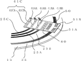
도 40는 도 39에 광원(16)과 수광 소자(22)(절대치용) 및 인크리멘탈용 수광 소자(32)를 더해서 표시한 것이다. 광원(16)으로부터의 광이 통과하는 장소에, 광원 슬릿(40)과 인크리멘탈용 광원 슬릿(50)이 형성되어 있다. FIG. 40 shows the
제 1 환상 슬릿 변위의 방향을 검출하기 위해서, 제 1 인덱스 슬릿(41A)은 도 39과 같이 위상을 어긋나게 한 A상 슬릿(41AA)과 B상 슬릿(41AB)으로 형성되어 있다. 이에 대응해서, 제 1 수광 소자(22A)도, 도 40과 같이 A상 수광부(22AA)와 B상 수광부(22AB)로 분할되어 있다. 마찬가지로, 제 2 인덱스 슬릿(41B)도, 위상을 어긋나게 한 A상 슬릿(41BA)과 B상 슬릿(41BB)으로 형성되고, 제 2 수광 소자(22B)도 A상 수광부(22BA)와 B상 수광부(22BB)로 분할되어 있다. In order to detect the direction of the first annular slit displacement, the first index slit 41A is formed of the A-phase slit 41AA and the B-phase slit 41AB, which are out of phase as shown in FIG. Correspondingly, the first light receiving element 22A is also divided into an A-phase light receiving portion 22AA and a B-phase light receiving portion 22AB as shown in FIG. 40. Similarly, the second index slit 41B is also formed of the A phase slit 41BA and the B phase slit 41BB which are out of phase, and the second light receiving element 22B is also the A phase light receiving portion 22BA and the B phase light receiving portion. It is divided into 22BB.
또한, 인크리멘탈용 인덱스 슬릿(51)도, 위상을 어긋나게 한 A상 슬릿(51A)과 B상 슬릿(51B)으로 형성되고, 인크리멘탈용 수광 소자(32)도 A상 수광부(32A)와 B상 수광부(32B)로 분할되어 있다. Incidentally, the incremental index slit 51 is also formed of an A-phase slit 51A and a B-phase slit 51B which are out of phase, and the incremental
또한, 본 실시예에서는 광원 슬릿(40)과 인덱스 슬릿(41)(41AA, 41AB, 41BA, 41BB)의 형상은 회전 디스크의 반경 방향에 수직인 리니어 형상이 바람직하고, 인크리멘탈용 광원 슬릿(50)과 인크리멘탈용 인덱스 슬릿(51)(51A, 51B)은 방사상의 형상이 바람직하다. In addition, in the present embodiment, the shape of the light source slit 40 and the index slit 41 (41AA, 41AB, 41BA, 41BB) is preferably a linear shape perpendicular to the radial direction of the rotating disk, and the incremental light source slit ( 50 and the incremental index slits 51 (51A, 51B) are preferably in a radial shape.
또한, 인크리멘탈 슬릿(35)의 방사상 슬릿의 검출 위치(예를 들면, 슬릿 중앙)에 있어서의 피치를 슬릿 피치로 하는 실질적인 슬릿 피치를, 환상 슬릿(25)의 슬릿 피치와 같게 하면, 회전 디스크(13)에 대한 인덱스 슬릿(41)과 인크리멘탈용 인덱스 슬릿(51)의 갭을 동일하게 할 수 있다. 한편, 3격자 광학계에서는 광원 슬릿에 선(線) 광원이 인덱스 슬릿(41) 및 인크리멘탈용 인덱스 슬릿(51) 상에 결상되는 갭의 조건이 격자의 피치에 의존한다는 것은 공지되어 있다. In addition, when the substantially slit pitch which makes the pitch in the detection position (for example, slit center) of the radial slit of the
한편, 광원 슬릿(40)과, 제 1 인덱스 슬릿의 A상 슬릿(41AA)과 B상 슬릿(41AB)과, 제 2 인덱스 슬릿의 A상 슬릿(41BA)과 B상 슬릿(41BB)과, 인크리멘탈용 광원 슬릿(50)과, 인크리멘탈용 인덱스 슬릿의 A상 슬릿(51A)과 B상 슬릿(51B)은 도 39에서 400으로 나타낸 동일 기판 상에 형성하는 것이 가능하다. On the other hand, the light source slit 40, the A phase slit 41AA and the B phase slit 41AB of the first index slit, the A phase slit 41BA and the B phase slit 41BB of the second index slit, and the ink The light source slit 50 for the retardation and the A-phase slit 51A and the B-phase slit 51B of the incremental index slit can be formed on the same substrate shown in FIG.
또한, 인덱스 슬릿(41) 및 인크리멘탈용 인덱스 슬릿(51)을 기판(400) 상에 형성하지 않고, 수광 소자 표면에 마스크를 형성하도록 수광 소자와 일체로 형성하는 것도 가능하다. Further, the index slit 41 and the incremental index slit 51 may be formed integrally with the light receiving element so as to form a mask on the surface of the light receiving element without forming the index slit 51 on the
이와 같이, 본 실시예에서는 실시예 5의 구성에 3격자 원리를 이용한 광학계를 적용하고 있기 때문에, 실시예 5의 효과에 더해서, 회전 디스크와 고정 슬릿 사이의 갭 변동에 강한 광학식 인코더를 실현할 수 있다. As described above, in the present embodiment, since the optical system using the three-lattice principle is applied to the configuration of the fifth embodiment, in addition to the effect of the fifth embodiment, an optical encoder resistant to the gap variation between the rotating disk and the fixed slit can be realized. .
또한, 본 실시예에서는 광원으로서 확산광을 이용하고 있다. 확산광을 이용함으로써, 하나의 광원으로 광원 슬릿(40)과 인크리멘탈용 광원 슬릿(50)을 동시에 조사하기 쉽게 되어서, 광원의 공통화가 용이하게 된다. 이로써 3격자 원리를 적용한 본 실시예의 장치는 보다 소형화에 적합하다는 특징이 있다.
In this embodiment, diffused light is used as the light source. By using the diffused light, it is easy to irradiate the light source slit 40 and the incremental light source slit 50 with one light source at the same time, thereby facilitating the commonization of the light source. As a result, the device of the present embodiment applying the three-lattice principle is suitable for further miniaturization.
<실시예 7> <Example 7>
도 41은 본 발명의 실시예 7을 나타내는 광학식 인코더의 측면도이다. Fig. 41 is a side view of the optical encoder showing the seventh embodiment of the present invention.
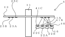
본 실시예에 따른 광학식 인코더(7)는 도 41에 나타낸 바와 같이, 제 3 환상 슬릿(25C)과, 제 3 환상 슬릿(25C)에 대응한 제 3 인덱스 슬릿(41C)과, 제 3 수광 소자(22C)를 갖는다. As shown in FIG. 41, the
본 실시예가, 실시예 6과 다른 점은 실시예 2에 대한 실시예 3과 마찬가지로, 회전 디스크 상에 제 3 환상 슬릿(25C)을 형성하고, 이에 대응하는 광학계인 제 3 인덱스 슬릿(41C) 및 제 3 수광 소자(22C)를 부가한 점으로, 3격자 광학계를 적용한 점에 대해서는 실시예 2, 3 및 6과 마찬가지다. The present embodiment differs from the sixth embodiment in the same way as in the third embodiment of the second embodiment, the third
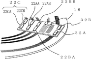
구체적인 구성을 도 42 및 도 43의 사시도를 이용해서 설명한다. The specific structure is demonstrated using the perspective view of FIG. 42 and FIG.
도 42는 본 실시예의 광학식 인코더의 구성을 나타내는 사시도로, 회전 디스크와 광원 슬릿 및 인덱스 슬릿의 배치를 나타낸 것이다. 도 39의 실시예 6의 사시도와 비교하면, 제 3 환상 슬릿(25C) 및 제 3 고정 슬릿(41C)이 추가된 것으로 되어 있다. 또한, 도 43은 도 42에 광원(16)과 제 3 수광 소자(22C)를 더해서 표시한 것이다. Fig. 42 is a perspective view showing the structure of the optical encoder of the present embodiment, showing the arrangement of the rotating disk, the light source slit, and the index slit. Compared with the perspective view of Example 6 of FIG. 39, the 3rd
이와 같이, 본 실시예에서는 실시예 6의 구성에 제 3 환상 슬릿과 이에 대응하는 광학계인 제 3 고정 슬릿 및 제 3 수광 소자를 부가했기 때문에, 실시예 6의 효과에 더해서, 회전 디스크의 중심과 회전축의 회전 중심이 어긋나서 부착된 경우에도, 0~360도의 전체 둘레에 걸쳐서 정확하게 회전 각도를 검출할 수 있는 광학식 인코더를 실현할 수 있다.
As described above, in the present embodiment, since the third annular slit, the third fixed slit and the third light receiving element, which are optical systems corresponding thereto, are added to the configuration of the sixth embodiment, the center of the rotating disk and Even when the rotational center of a rotating shaft is shifted and attached, the optical encoder which can detect a rotation angle accurately over the whole periphery of 0-360 degree can be implement | achieved.
<본 발명의 각 실시예에 따른 모터 및 모터 시스템> <Motors and Motor Systems According to Embodiments of the Present Invention>
이상, 본 발명의 각 실시예에 따른 광학식 인코더에 대해서 설명했다. 한편, 본 발명의 각 실시예에 따른 모터 시스템(1000) 또는 모터(1010)는 상기 실시예 1~7에서 설명한 광학식 인코더(1~7) 중 어느 하나를 갖는다. In the above, the optical encoder which concerns on each Example of this invention was demonstrated. Meanwhile, the
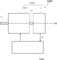
도 44는 본 발명의 각 실시예에 따른 모터 시스템 및 모터의 구성을 나타내는 블록도이다. 한편, 이 도 44에서는 광학식 인코더의 예로서, 실시예 1에 따른 광학식 인코더(1)인 경우를 예시하고 있다. 그러나, 모터 시스템(1000) 및 모터(1001)가 갖는 광학식 인코더는 상기 실시예 1~7에 따른 광학식 인코더(1~7) 중 어느 하나여도 된다. 44 is a block diagram showing the configuration of a motor system and a motor according to each embodiment of the present invention. 44 shows an example of the optical encoder, which is the
도 44에 나타낸 바와 같이, 본 발명의 각 실시예에 따른 모터 시스템(1000)은 모터(1010)와, 제어부(1020)를 갖는다. 그리고, 모터(1010)는 모터부(1011)와, 광학식 인코더(1)를 갖는다. As shown in FIG. 44, the
모터부(1011)는 제어부(1020)로부터의 제어 신호에 의해 회전축(11)을 회전시킴으로써, 회전력을 출력한다. 한편, 이 회전축(11)은 광학식 인코더(1)의 회전축(11)과 일체로 또는 별체로 연결해서 형성되기 때문에, 모터부(1010) 1회전에 추종하여, 회전 디스크(13)가 회전한다. 한편, 광학식 인코더(1)는 상술한 바와 같이, 이 회전 디스크(13)의 회전에 의한 회전 각도 θ를 검출하고, 이 회전 각도 θ는 제어부(1020)로 보내어진다. 제어부(1020)는 회전 각도 θ가 원하는 값(예컨대 상위 제어 장치(도시 생략)에 의해 지시된 값)이 되도록 모터부(1011)에 제어 신호를 출력함으로써 모터부(1011)를 제어한다. 따라서, 본 발명의 각 실시예에 따른 모터 시스템(1000) 또는 모터(1010)에 의하면, 상기 광학식 인코더(1~7)가 내는 작용 효과 등을 발휘하는 것이 가능하다. The
한편, 상술한 바와 같이, 이 모터 시스템(1000) 또는 모터(1010)에는 상기 실시예 1~7에서 설명한 광학식 인코더(1~7) 중 어느 하나를 사용할 수 있다. 이들 각 실시예에 따른 광학식 인코더(1~7)의 개요에 대해서, 더 설명하면 이하와 같다. On the other hand, as described above, any one of the
본 발명의 1의 실시예에 따른 광학식 인코더는 Optical encoder according to an embodiment of the present invention
회전축에 부착되어서, 상기 회전축의 회전 중심에 대해 편심되게 형성된 복수의 등피치의 동심원 슬릿 패턴으로 이루어지는 환상 슬릿을 갖는 회전 디스크와, A rotating disk attached to the rotating shaft, the rotating disk having an annular slit formed of a plurality of equal pitch concentric slit patterns formed eccentric with respect to the rotation center of the rotating shaft,
고정 부재에 마련되고, 상기 환상 슬릿을 조사하는 광원 및 상기 환상 슬릿으로부터의 투과광 또는 반사광을 검출하는 절대치용 검출부A detection unit for absolute value provided in the fixing member and detecting a light source for irradiating the annular slit and transmitted or reflected light from the annular slit.
를 구비하되, Respectively,
상기 환상 슬릿은 서로 다른 방향으로 편심된 제 1 환상 슬릿과 제 2 환상 슬릿을 갖고, The annular slit has a first annular slit and a second annular slit eccentric in different directions,
상기 절대치용 검출부는 상기 제 1 환상 슬릿에 대응하는 제 1 검출부와 상기 제 2 환상 슬릿에 대응하는 제 2 검출부를 가지며, The absolute value detection unit has a first detection unit corresponding to the first annular slit and a second detection unit corresponding to the second annular slit,
상기 광학식 인코더는 상기 절대치용 검출부로부터의 검출 신호로부터 상기 회전축의 절대 회전 각도를 검출한다. The optical encoder detects the absolute rotation angle of the rotation shaft from the detection signal from the absolute value detection section.
이 실시예에 의하면, 광학식 인코더가, 회전 디스크 상에 서로 다른 방향으로 편심된 제 1 환상 슬릿 및 제 2 환상 슬릿과, 고정 부재에 제 1 환상 슬릿에 대응하는 제 1 검출부 및 제 2 환상 슬릿에 대응하는 제 2 검출부를 구비하고 있기 때문에, 0~360도의 전체 둘레에 걸쳐서 회전축의 각도의 절대치를 검출할 수 있다. 또한, 광원 및 제 1 검출부와 제 2 검출부 등의 광학 부품을 1개소에 집약하여 배치할 수 있기 때문에, 장치를 소형으로 할 수 있다. According to this embodiment, the optical encoder includes a first annular slit and a second annular slit, which are eccentric in different directions on the rotating disk, and a first detection portion and a second annular slit corresponding to the first annular slit in the fixing member. Since the corresponding 2nd detection part is provided, the absolute value of the angle of a rotating shaft can be detected over the whole circumference of 0-360 degree. Moreover, since the light source and optical components, such as a 1st detection part and a 2nd detection part, can be collectively arrange | positioned at one place, an apparatus can be made small.
또한, 상기 제 1 환상 슬릿과 상기 제 2 환상 슬릿의 슬릿 피치가, 상기 회전 디스크의 중심에 대한 각각의 편심량 이상이여도 된다. Moreover, the slit pitch of the said 1st annular slit and the said 2nd annular slit may be more than each eccentricity with respect to the center of the said rotating disk.
이와 같이 구성함으로써, 또한, 제 1 환상 슬릿과 제 2 환상 슬릿의 슬릿 피치를 회전 디스크의 중심에 대한 각각의 편심량 이상이라고 하면, 환상 슬릿의 변위량이 환상 슬릿의 1피치 이내가 되기 때문에, 제 1 검출부 및 제 2 검출부로부터의 검출 신호에서 변위량이 일의적으로 정해져서, 신호 처리 장치가 간단하게 된다. In such a configuration, when the slit pitches of the first annular slit and the second annular slit are equal to or more than the respective eccentricity with respect to the center of the rotating disk, the displacement amount of the annular slit is within 1 pitch of the annular slit. The displacement amount is uniquely determined in the detection signals from the detection unit and the second detection unit, thereby simplifying the signal processing apparatus.
상기 제 1 검출부는 상기 제 1 환상 슬릿과 동일 피치의 슬릿이 형성된 제 1 고정 슬릿 및 상기 제 1 고정 슬릿으로부터의 투과광을 검출하는 제 1 수광 소자로 구성되고, 상기 제 2 검출부는 상기 제 2 환상 슬릿과 동일 피치의 슬릿이 형성된 제 2 고정 슬릿 및 상기 제 2 고정 슬릿으로부터의 투과광을 검출하는 제 2 수광 소자로 구성되어 있어도 된다. The first detection unit includes a first fixed slit in which a slit having the same pitch as the first annular slit is formed, and a first light receiving element that detects transmitted light from the first fixed slit, and the second detection unit includes the second annular slit. It may be comprised with the 2nd fixed slit in which the slit of the same pitch as the slit was formed, and the 2nd light receiving element which detects the transmitted light from the said 2nd fixed slit.
상기 제 1 검출부는 상기 제 1 환상 슬릿과 동일 피치의 슬릿이 형성된 슬릿 패턴 상의 수광 소자로 구성되고, 상기 제 2 검출부는 상기 제 2 환상 슬릿과 동일 피치의 슬릿이 형성된 슬릿 패턴상의 수광 소자로 구성되어 있어도 된다. The first detector includes a light receiving element on a slit pattern on which a slit of the same pitch is formed as the first annular slit, and the second detector includes a light receiving element on a slit pattern on which a slit of the same pitch is formed with the second annular slit. You may be.
상기 회전 디스크는 상기 회전 디스크의 중심에 대해 방사상으로 형성된 인크리멘탈 슬릿을 구비하고, 상기 고정 부재에 상기 인크리멘탈 슬릿을 조사하는 인크리멘탈용 광원을 및 상기 인크리멘탈 슬릿으로부터의 투과광 또는 반사광을 검출하는 인크리멘탈용 검출부를 구비하고 있어도 된다. The rotating disk includes an incremental slit radially formed with respect to the center of the rotating disk, the incremental light source for irradiating the incremental slit to the fixing member and the transmitted light from the incremental slit or You may be provided with the incremental detection part which detects reflected light.
이와 같이 구성함으로써, 또한, 회전 디스크가 인크리멘탈 슬릿을 구비하고, 고정 부재에 인크리멘탈용 검출부를 구비하면, 고분해능의 절대 각도 신호가 얻어진다. With such a configuration, when the rotating disk includes the incremental slit and the fixing member includes the incremental detection unit, a high resolution absolute angle signal is obtained.
상기 환상 슬릿과 상기 인크리멘탈 슬릿을 공통의 광원으로 조사해도 된다. The annular slit and the incremental slit may be irradiated with a common light source.
상기 광원은 상기 광원으로부터의 조사광을 제한하는 광원 슬릿을 구비하고, 상기 광원 슬릿으로 제한되어 상기 제 1 환상 슬릿에서 반사된 광을 상기 제 1 검출부에서 검출하며, 상기 광원 슬릿으로 제한되어, 상기 제 2 환상 슬릿에서 반사된 광을 상기 제 2 검출부에서 검출해도 된다. The light source includes a light source slit for limiting the irradiation light from the light source, the first detection unit detects the light reflected by the first annular slit, which is limited to the light source slit, and is limited to the light source slit. The light reflected by the second annular slit may be detected by the second detection unit.
이와 같이 구성함으로써, 또한, 광원이, 광원으로부터의 조사광을 제한하는 광원 슬릿을 구비하면, 회전 디스크와 고정 슬릿 사이의 갭 변동에 강한 광학식 인코더를 실현할 수 있다. By configuring in this way, when the light source is equipped with the light source slit which restricts the irradiation light from a light source, the optical encoder which is strong in the gap variation between a rotating disk and a fixed slit can be implement | achieved.
상기 회전 디스크는 상기 회전 디스크의 중심에 대해 방사상으로 형성된 인크리멘탈 슬릿을 구비하고, The rotating disk has an incremental slit radially formed with respect to the center of the rotating disk,
상기 광원은 상기 광원으로부터의 조사광을 제한하는 인크리멘탈용 광원 슬릿을 구비하며, The light source has an incremental light source slit for limiting the irradiation light from the light source,
상기 고정 부재에, 상기 광원에서 조사된 상기 인크리멘탈 슬릿으로부터의 반사광을 검출하는 인크리멘탈용 검출부를 구비해도 된다. The fixing member may include an incremental detection unit that detects the reflected light from the incremental slit irradiated from the light source.
상기 인크리멘탈용 검출부로부터 얻어지는 반복 신호를 내삽한 내삽 신호로 상기 절대치 검출부로부터의 검출 신호를 바탕으로 산출한 상기 절대 회전 각도를 보간해도 된다. You may interpolate the said absolute rotation angle computed based on the detection signal from the said absolute value detection part by the interpolation signal which interpolated the repeating signal obtained from the said incremental detection part.
상기 제 1 환상 슬릿, 상기 제 2 환상 슬릿 및 상기 인크리멘탈 슬릿의 실질적인 슬릿 피치가 같아도 된다. Substantial slit pitches of the first annular slit, the second annular slit, and the incremental slit may be the same.
본 발명의 일 실시예에 따른 광학식 인코더는, Optical encoder according to an embodiment of the present invention,
회전축에 부착되고, 상기 회전축의 회전 중심에 대해 편심하게 형성된 복수의 등피치의 동심원 슬릿 패턴으로 이루어지는 환상 슬릿을 갖는 회전 디스크와, A rotating disk attached to the rotating shaft, the rotating disk having an annular slit formed of a plurality of equal pitch concentric slit patterns formed eccentric with respect to the rotation center of the rotating shaft;
고정 부재에 마련되고, 상기 환상 슬릿을 조사하는 광원 및 상기 환상 슬릿으로부터의 투과광 또는 반사광을 검출하는 절대치용 검출부A detection unit for absolute value provided in the fixing member and detecting a light source for irradiating the annular slit and transmitted or reflected light from the annular slit.
를 구비하되, Respectively,
상기 환상 슬릿은 The annular slit is
서로 다른 방향으로 편심된 제 1 환상 슬릿 및 제 2 환상 슬릿과, A first annular slit and a second annular slit eccentric in different directions,
상기 제 1 환상 슬릿 및 제 2 환상 슬릿과 편심 방향 또는 편심량 중 적어도 어느 하나가 상기 제 1 환상 슬릿 및 제 2 환상 슬릿과 다르게 형성된 제 3 환상 슬릿 A third annular slit in which at least one of the first annular slit and the second annular slit and an eccentric direction or an eccentric amount is formed differently from the first annular slit and the second annular slit
을 갖고, With
상기 절대치용 검출부는 상기 제 1~제 3 환상 슬릿에 각각 대응하는 제 1~제 3 검출부를 가지며, The absolute value detecting unit has first to third detecting units respectively corresponding to the first to third annular slits,
상기 광학식 인코더는 상기 절대치용 검출부로부터의 검출 신호로부터 상기 회전축의 절대 회전 각도를 검출한다. The optical encoder detects the absolute rotation angle of the rotation shaft from the detection signal from the absolute value detection section.
이 실시예에 의하면, 광학식 인코더가, 회전 디스크 상에, 서로 다른 방향으로 편심된 제 1 환상 슬릿 및 제 2 환상 슬릿과 제 1 환상 슬릿 및 제 2 환상 슬릿과 편심 방향 또는 편심량 중 적어도 어느 하나가 다르게 형성된 제 3 환상 슬릿을 구비하고, 고정 부재에, 제 1~제 3 환상 슬릿에 각각 대응하는 제 1~제 3 검출부를 구비하고 있기 때문에, 회전 디스크의 중심과 회전축의 회전 중심이 어긋나게 부착된 경우에도, 0~360도의 전체 둘레에 걸쳐서 정확하게 회전 각도를 검출할 수 있다. According to this embodiment, the optical encoder is characterized in that at least one of the first annular slit and the second annular slit and the first annular slit and the second annular slit and the eccentric direction or the amount of eccentricity on the rotating disk are eccentric in different directions. Since the third annular slit is formed differently, and the fixing member is provided with first to third detection portions respectively corresponding to the first to third annular slits, the center of the rotating disk and the rotation center of the rotating shaft are attached to each other. Even in this case, the rotation angle can be detected accurately over the entire circumference of 0 to 360 degrees.
상기 제 3 환상 슬릿이, 상기 회전 디스크의 중심에 대해 편심없이 형성된 복수의 동심원 슬릿으로 이루어져도 된다. The third annular slit may consist of a plurality of concentric slit formed without eccentricity with respect to the center of the rotating disk.
이와 같이 구성함으로써, 또한 제 3 환상 슬릿을 편심없이 형성하면, 간단한 신호 처리로, 회전 디스크의 중심과 회전축의 회전 중심이 어긋나게 부착된 경우에도, 0~360도의 전체 둘레에 걸쳐서 정확하게 회전 각도를 검출할 수 있다. With this configuration, if the third annular slit is formed without eccentricity, the rotation angle can be accurately detected over the entire circumference of 0 to 360 degrees even when the center of the rotating disk and the rotation center of the rotating shaft are shifted by simple signal processing. can do.
상기 제 1 환상 슬릿~제 3 환상 슬릿의 모든 슬릿 피치가, 상기 회전 디스크의 중심에 대한 각각의 편심량 이상이여도 된다. All the slit pitches of the said 1st annular slit-the 3rd annular slit may be more than each eccentricity with respect to the center of the said rotating disk.
상기 제 1~제 3 검출부는 각각 상기 제 1~제 3 환상 슬릿과 동일 피치의 슬릿이 형성된 제 1~제 3 고정 슬릿 및 상기 제 1~제 3 고정 슬릿으로부터의 투과광을 각각 검출하는 제 1~제 3 수광 소자로 구성되어 있어도 된다. The first to third detection units, respectively, the first to the third fixed slit having the same pitch as the first to the third annular slit and the first to third to detect the transmitted light from the first to the third fixed slit, respectively You may be comprised with the 3rd light receiving element.
상기 제 1~제 3 검출부는 각각 상기 제 1~제 3 환상 슬릿과 동일 피치의 슬릿이 형성된 슬릿 패턴 상의 수광 소자로 구성되어 있어도 된다. The said 1st-3rd detection part may be comprised by the light receiving element on the slit pattern in which the slit of the same pitch as the said 1st-3rd annular slit was formed, respectively.
상기 회전 디스크는 상기 회전 디스크의 중심에 대해 방사상으로 형성된 인크리멘탈 슬릿을 구비하고, 상기 고정 부재에, 상기 인크리멘탈 슬릿을 조사하는 인크리멘탈용 광원을 및 상기 인크리멘탈 슬릿으로부터의 투과광 또는 반사광을 검출하는 인크리멘탈용 검출부를 구비해도 된다. The rotating disk has an incremental slit radially formed with respect to the center of the rotating disk, the fixing member, an incremental light source for irradiating the incremental slit and transmitted light from the incremental slit Or you may provide the incremental detection part which detects reflected light.
상기 환상 슬릿과 상기 인크리멘탈 슬릿을 공통의 광원으로 조사해도 된다.The annular slit and the incremental slit may be irradiated with a common light source.
상기 광원은 상기 광원으로부터의 조사광을 제한하는 광원 슬릿을 갖고, 상기 광원 슬릿으로 제한되어 상기 제 1~제 3 환상 슬릿에서 반사된 광을 각각 상기 제 1~제 3 검출부에서 검출해도 된다. The said light source has a light source slit which restricts the irradiation light from the said light source, and may be detected by the said 1st-3rd detection part each the light reflected by the said 1st-3rd annular slit by the said light source slit, respectively.
상기 회전 디스크는 상기 회전 디스크의 중심에 대해 방사상으로 형성된 인크리멘탈 슬릿을 갖고, The rotating disk has an incremental slit radially formed with respect to the center of the rotating disk,
상기 광원은 상기 광원으로부터의 조사광을 제한하는 인크리멘탈용 광원 슬릿을 가지며, The light source has an incremental light source slit for limiting the irradiation light from the light source,
상기 광학식 인코더는 상기 고정 부재에, 상기 광원에서 조사된 상기 인크리멘탈 슬릿으로부터의 반사광을 검출하는 인크리멘탈용 검출부를 가져도 된다. The optical encoder may have, on the fixing member, an incremental detection unit that detects reflected light from the incremental slit irradiated from the light source.
상기 인크리멘탈용 검출부로부터 얻어지는 반복 신호를 내삽한 내삽 신호로 상기 절대치 검출부로부터의 검출 신호를 바탕으로 산출한 상기 절대 회전 각도를 보간해도 된다. You may interpolate the said absolute rotation angle computed based on the detection signal from the said absolute value detection part by the interpolation signal which interpolated the repeating signal obtained from the said incremental detection part.
상기 제 1~제 3 환상 슬릿 및 상기 인크리멘탈 슬릿의 실질적인 슬릿 피치가 같아도 된다. Substantial slit pitches of the first to third annular slits and the incremental slit may be the same.
상기 광학식 인코더는 The optical encoder
상기 제 1 검출부로부터의 신호를 바탕으로 상기 제 1 환상 슬릿의 상기 회전축의 반경 방향으로의 변위인 제 1 변위를 산출하는 제 1 변위 검출 처리부와, A first displacement detection processor for calculating a first displacement, which is a displacement in the radial direction of the rotation axis of the first annular slit, based on the signal from the first detector;
상기 제 2 검출부로부터의 신호를 바탕으로 상기 제 2 환상 슬릿의 상기 회전축의 반경 방향으로의 변위인 제 2 변위를 산출하는 제 2 변위 검출 처리부와, A second displacement detection processing unit calculating a second displacement, which is a displacement in the radial direction of the rotation axis of the second annular slit, based on the signal from the second detection unit;
상기 제 1 변위와 상기 제 2 변위를 바탕으로 상기 회전 디스크의 회전 각도를 산출하는 각도 검출 처리부 An angle detection processor configured to calculate a rotation angle of the rotating disk based on the first displacement and the second displacement
를 갖는 신호 처리 장치를 더 구비해도 된다. You may further include the signal processing apparatus which has a.
이와 같이 구성함으로써, 또한, 서로 다른 방향으로 편심된 제 1 환상 슬릿 및 제 2 환상 슬릿을 구비한 광학식 인코더의 신호 처리 방법에 있어서, 제 1 및 제 2 환상 슬릿의 반경 방향의 변위를 산출하고 이 변위로부터 회전 각도를 검출하고 있기 때문에, 양변위로부터 회전축의 회전 각도는 일의적으로 정해져서, 0~360도의 전체 둘레에 걸쳐서 회전축의 각도의 절대치를 검출할 수 있다. In this way, in the signal processing method of the optical encoder having the first annular slit and the second annular slit which are eccentric in different directions, the radial displacements of the first and second annular slits are calculated and Since the rotation angle is detected from the displacement, the rotation angle of the rotation shaft is uniquely determined from both the displacements, and the absolute value of the angle of the rotation shaft can be detected over the entire circumference of 0 to 360 degrees.
상기 광학식 인코더는 The optical encoder
상기 제 1 검출부로부터의 신호와 상기 제 2 검출부로부터의 신호를 전환하는 전환 처리부와, A switching processor for switching a signal from the first detector and a signal from the second detector;
상기 전환 처리부에 의해 상기 제 1 검출부로부터의 신호가 입력된 경우에는 상기 제 1 변위를, 상기 전환 처리부에 의해 상기 제 2 검출부로부터의 신호가 입력된 경우에는 상기 제 2 변위를 검출하는 변위 검출 처리부와, A displacement detection processing unit that detects the first displacement when the signal from the first detection unit is input by the switching processing unit and the second displacement when the signal from the second detection unit is input by the switching processing unit. Wow,
상기 제 1 변위와 상기 제 2 변위를 바탕으로 상기 회전 디스크의 회전 각도를 산출하는 각도 검출 처리부An angle detection processor configured to calculate a rotation angle of the rotating disk based on the first displacement and the second displacement
를 갖는 신호 처리 장치를 더 구비해도 된다. You may further include the signal processing apparatus which has a.
이와 같이 구성함으로써, 또한, 서로 다른 방향으로 편심된 제 1 환상 슬릿 및 제 2 환상 슬릿과 제 1 환상 슬릿 및 제 2 환상 슬릿과 편심 방향 또는 편심량 중 적어도 어느 하나가 다르게 형성된 제 3 환상 슬릿을 구비한 광학식 인코더의 신호 처리 방법에 있어서, 제 1~제 3 환상 슬릿의 반경 방향의 변위를 산출하고 이 변위로부터 회전 각도를 검출하고 있기 때문에, 회전 중심이 어긋나게 부착된 경우에도, 0~360도의 전체 둘레에 걸쳐서 정확하게 회전 각도를 검출할 수 있다. In this configuration, the first annular slit and the second annular slit, the first annular slit, the second annular slit, and the third annular slit are formed differently from each other in the eccentric direction or the amount of eccentricity. In the optical signal processing method of the optical encoder, since the displacement of the first to third annular slits is calculated in the radial direction and the rotation angle is detected from the displacement, even when the rotation center is shifted, the entire range of 0 to 360 degrees is obtained. The angle of rotation can be detected accurately over the circumference.
상기 광학식 인코더는 The optical encoder
상기 제 1 변위 및 상기 제 2 변위를 산출함과 아울러 상기 제 1 변위 및 상기 제 2 변위를 바탕으로 상기 회전 디스크의 회전 각도를 산출하는 변위 검출 처리부와, A displacement detection processor for calculating the first displacement and the second displacement and calculating a rotation angle of the rotating disk based on the first displacement and the second displacement;
상기 변위 검출 처리부로의 입력 신호를 전환하는 전환 처리부와, 상기 변위 검출 처리부에서 산출된 상기 제 1 변위 및 상기 제 2 변위를 기억하는 기억부A switching processing unit for switching the input signal to the displacement detection processing unit, and a storage unit storing the first displacement and the second displacement calculated by the displacement detection processing unit.
를 갖는 신호 처리 장치를 더 구비하되, Further provided with a signal processing device having,
상기 변위 검출 처리부는 상기 전환 처리부에 의해서 상기 제 1 검출부로부터의 신호가 입력된 경우, 상기 제 1 변위를 산출하고, 상기 제 2 검출부로부터의 신호가 입력된 경우, 상기 제 2 변위를 산출하며, 상기 기억부에 기억된 상기 제 1 변위 및 상기 제 2 변위가 입력된 경우, 회전 각도를 산출할 수도 있다. The displacement detection processing unit calculates the first displacement when the signal from the first detection unit is input by the switching processing unit, and calculates the second displacement when the signal from the second detection unit is input, When the first displacement and the second displacement stored in the storage unit are input, the rotation angle may be calculated.
상기 광학식 인코더는 The optical encoder
상기 제 1 검출부로부터의 신호를 바탕으로 상기 제 1 환상 슬릿의 상기 회전축의 반경 방향으로의 변위인 제 1 변위를 산출하는 제 1 변위 검출 처리부와, A first displacement detection processor for calculating a first displacement, which is a displacement in the radial direction of the rotation axis of the first annular slit, based on the signal from the first detector;
상기 제 2 검출부로부터의 신호를 바탕으로 상기 제 2 환상 슬릿의 상기 회전축의 반경 방향으로의 변위인 제 2 변위를 산출하는 제 2 변위 검출 처리부와, A second displacement detection processing unit calculating a second displacement, which is a displacement in the radial direction of the rotation axis of the second annular slit, based on the signal from the second detection unit;
상기 제 3 검출부로부터의 신호를 바탕으로 상기 제 3 환상 슬릿의 상기 회전축의 반경 방향으로의 변위인 제 3 변위를 산출하는 제 3 변위 검출 처리부와, A third displacement detection processor for calculating a third displacement, which is a displacement in the radial direction of the rotation axis of the third annular slit, based on the signal from the third detection unit;
상기 제 1 변위~제 3 변위를 바탕으로 상기 회전 디스크의 회전 각도를 산출하는 각도 검출 처리부An angle detection processor that calculates a rotation angle of the rotating disk based on the first to third displacements.
를 갖는 신호 처리 장치를 더 구비해도 된다. You may further include the signal processing apparatus which has a.
상기 제 1~제 3 검출부로부터의 신호를 전환하는 전환 처리부와, A switching processor for switching signals from the first to third detectors;
상기 전환 처리부에 의해 상기 제 1 검출부로부터의 신호가 입력된 경우에는 상기 제 1 변위를, 상기 전환 처리부에 의해 상기 제 2 검출부로부터의 신호가 입력된 경우에는 상기 제 2 변위를, 상기 전환 처리부에 의해 상기 제 3 검출부로부터의 신호가 입력된 경우에는 상기 제 3 변위를 검출하는 변위 검출 처리부와, The first displacement is input when the signal from the first detection unit is input by the switching processing unit, and the second displacement is input when the signal from the second detection unit is input by the switching processing unit. A displacement detection processor that detects the third displacement when a signal from the third detector is input by the third detector;
상기 제 1 변위~제 3 변위를 바탕으로 상기 회전 디스크의 회전 각도를 산출하는 각도 검출 처리부An angle detection processor that calculates a rotation angle of the rotating disk based on the first to third displacements.
를 갖는 신호 처리 장치를 더 구비해도 된다.You may further include the signal processing apparatus which has a.
상기 광학식 인코더는 The optical encoder
상기 제 1~제 3 변위를 산출함과 아울러 상기 제 1~제 3 변위를 바탕으로 상기 회전 디스크의 회전 각도를 산출하는 변위 검출 처리부와, A displacement detection processor configured to calculate the first to third displacements and to calculate a rotation angle of the rotating disk based on the first to third displacements;
상기 변위 검출 처리부로의 입력 신호를 전환하는 전환 처리부와, A switching processor that switches the input signal to the displacement detection processor;
상기 변위 검출 처리부에서 산출된 상기 제 1~제 3 변위를 기억하는 기억부A storage unit for storing the first to third displacements calculated by the displacement detection processing unit
를 갖는 신호 처리 장치를 더 구비하되, Further provided with a signal processing device having,
상기 변위 검출 처리부는 상기 전환 처리부에 의해서 상기 제 1~제 3 검출부로부터의 신호가 입력된 경우, 각각 상기 제 1~제 3 변위를 산출하고, 상기 기억부에 기억된 상기 제 1 변위~제 3 변위가 입력된 경우, 회전 각도를 산출해도 된다. The said displacement detection processing part calculates the said 1st-3rd displacement, respectively, when the signal from the said 1st-3rd detection part is input by the said switching process part, and the said 1st-3rd displacement stored in the said memory part When the displacement is input, the rotation angle may be calculated.
본 발명의 일 실시예에 따른 광학식 인코더의 신호 처리 방법은 Signal processing method of the optical encoder according to an embodiment of the present invention
회전축에 부착되고 상기 회전축의 회전 중심에 대해 편심되게 형성된 복수의 등피치의 동심원 슬릿 패턴으로 이루어지는 환상 슬릿을 갖는 회전 디스크와, 고정 부재에 마련되고, 상기 환상 슬릿을 조사하는 광원 및 상기 환상 슬릿으로부터의 투과광 또는 반사광을 검출하는 절대치용 검출부를 구비하되, 상기 환상 슬릿은 서로 다른 방향으로 편심된 제 1 환상 슬릿과 제 2 환상 슬릿을 갖고, 상기 절대치용 검출부는 상기 제 1 환상 슬릿에 대응하는 제 1 검출부와 상기 제 2 환상 슬릿에 대응하는 제 2 검출부를 갖고, 상기 절대치용 검출부로부터의 검출 신호로부터 상기 회전축의 절대 회전 각도를 검출하는 광학식 인코더의 신호 처리 방법으로서, A rotating disk having an annular slit attached to a rotating shaft and formed of a plurality of equal pitch concentric slit patterns formed eccentric with respect to the rotation center of the rotating shaft, a light source provided on a fixing member, and irradiating the annular slit from the annular slit An absolute value detecting unit for detecting transmitted or reflected light, the annular slit having a first annular slit and a second annular slit which are eccentric in different directions, the absolute detecting unit having a first corresponding to the first annular slit A signal processing method of an optical encoder having a detection unit and a second detection unit corresponding to the second annular slit, and detecting an absolute rotation angle of the rotation axis from a detection signal from the detection unit for absolute values.
상기 제 1 검출부로부터의 신호를 바탕으로 상기 제 1 환상 슬릿의 상기 회전축의 반경 방향으로의 변위인 제 1 변위를 산출하고, A first displacement, which is a displacement in the radial direction of the rotation axis of the first annular slit, is calculated based on the signal from the first detection unit,
상기 제 2 검출부로부터의 신호를 바탕으로 상기 제 2 환상 슬릿의 상기 회전축의 반경 방향으로의 변위인 제 2 변위를 산출하며, Calculating a second displacement which is a displacement in the radial direction of the rotation axis of the second annular slit based on the signal from the second detection unit,
상기 제 1 변위와 상기 제 2 변위를 바탕으로 상기 회전 디스크의 회전 각도를 산출한다. The rotation angle of the rotating disk is calculated based on the first displacement and the second displacement.
본 발명의 일 실시예에 따른 광학식 인코더의 신호 처리 방법은 Signal processing method of the optical encoder according to an embodiment of the present invention
회전축에 부착되고 상기 회전축의 회전 중심에 대해 편심되게 형성된 복수의 등피치의 동심원 슬릿 패턴으로 이루어지는 환상 슬릿을 갖는 회전 디스크와, 고정 부재에 마련되고, 상기 환상 슬릿을 조사하는 광원 및 상기 환상 슬릿으로부터의 투과광 또는 반사광을 검출하는 절대치용 검출부를 구비하되, 상기 환상 슬릿은 서로 다른 방향으로 편심된 제 1 환상 슬릿 및 제 2 환상 슬릿과, 상기 제 1 환상 슬릿 및 제 2 환상 슬릿과 편심 방향 또는 편심량 중 적어도 어느 하나가 상기 제 1 환상 슬릿 및 제 2 환상 슬릿과 다르게 형성된 제 3 환상 슬릿을 갖고, 상기 절대치용 검출부는 상기 제 1~제 3 환상 슬릿에 각각 대응하는 제 1~제 3 검출부를 가지며, 상기 절대치용 검출부로부터의 검출 신호로부터 상기 회전축의 절대 회전 각도를 검출하는 상기 광학식 인코더의 신호 처리 방법으로서, A rotating disk having an annular slit attached to a rotating shaft and formed of a plurality of equal pitch concentric slit patterns formed eccentric with respect to the rotation center of the rotating shaft, a light source provided on a fixing member, and irradiating the annular slit from the annular slit An absolute value detecting unit for detecting transmitted or reflected light, wherein the annular slit includes a first annular slit and a second annular slit which are eccentric in different directions, and the first annular slit and the second annular slit in an eccentric direction or an amount of eccentricity. At least one has a third annular slit formed differently from the first annular slit and the second annular slit, wherein the absolute value detecting unit has first to third detection units respectively corresponding to the first to third annular slits, The optical type for detecting an absolute rotation angle of the rotation axis from a detection signal from the detection unit for absolute value A signal processing method of the coder,
상기 제 1 검출부로부터의 신호를 바탕으로 상기 제 1 환상 슬릿의 상기 회전축의 반경 방향으로의 변위인 제 1 변위를 산출하고, A first displacement, which is a displacement in the radial direction of the rotation axis of the first annular slit, is calculated based on the signal from the first detection unit,
상기 제 2 검출부로부터의 신호를 바탕으로 상기 제 2 환상 슬릿의 상기 회전축의 반경 방향으로의 변위인 제 2 변위를 산출하며, Calculating a second displacement which is a displacement in the radial direction of the rotation axis of the second annular slit based on the signal from the second detection unit,
상기 제 3 검출부로부터의 신호를 바탕으로 상기 제 3 환상 슬릿의 상기 회전축의 반경 방향으로의 변위인 제 3 변위를 산출하고, A third displacement, which is a displacement in the radial direction of the rotation axis of the third annular slit, is calculated based on the signal from the third detection unit,
상기 제 1 변위~제 3 변위를 바탕으로 상기 회전 디스크의 회전 각도를 산출한다. The rotation angle of the said rotating disk is computed based on the said 1st-3rd displacement.
본 발명은 2009년 3월 9일에 일본 특허청에 출원된 일본 우선권 특허 출원 제 2009-054848 호에 개시된 청구 대상을 포함하며, 이 출원의 내용을 여기에 참조로서 포함한다. The present invention includes the subject matter disclosed in Japanese Priority Patent Application No. 2009-054848 filed with the Japan Patent Office on March 9, 2009, the contents of which are incorporated herein by reference.
설계 요구 사항 및 다른 요인에 따라서 다양한 수정, 조합, 하위 조합 및 변경이 있을 수 있지만, 당업자라면, 이는 첨부된 특허청구범위 혹은 그 등가물의 범주 내에 포함된다는 것을 이해할 것이다. Various modifications, combinations, subcombinations, and changes may be made depending on design requirements and other factors, but those skilled in the art will understand that they are included within the scope of the appended claims or their equivalents.
Claims (13)
상기 회전 디스크에 마련되고, 상기 회전 디스크의 회전 중심에 대해 편심되게 형성된 복수의 등피치의 동심원 슬릿 패턴을 포함하는 환상 슬릿과,
상기 환상 슬릿에 광을 조사하는 광원과,
상기 광원으로부터 조사되어 상기 환상 슬릿에서 투과 또는 반사된 투과광 또는 반사광을 검출하여 검출 신호를 출력하는 절대치용 검출부와,
상기 절대치용 검출부에서 검출된 검출 신호에 기초해서, 상기 회전 디스크의 절대 회전 각도를 검출하는 신호 처리 장치
를 구비하되,
상기 환상 슬릿은 서로 다른 방향으로 편심된 제 1 환상 슬릿 및 제 2 환상 슬릿을 갖고,
상기 절대치용 검출부는 상기 제 1 환상 슬릿에 대응하는 제 1 검출부 및 상기 제 2 환상 슬릿에 대응하는 제 2 검출부를 갖는
광학식 인코더.
A rotating disk attached to the rotating shaft and rotatable according to the rotation of the rotating shaft;
An annular slit provided on said rotating disk, said annular slit comprising a plurality of equi-pitch concentric slit patterns formed eccentrically with respect to the rotation center of said rotating disk;
A light source for irradiating light to the annular slit;
An absolute value detector for detecting transmitted light or reflected light transmitted from or reflected by the annular slit and outputting a detection signal;
A signal processing device for detecting an absolute rotation angle of the rotating disk based on the detection signal detected by the absolute value detecting unit.
Provided with
The annular slit has a first annular slit and a second annular slit eccentric in different directions,
The absolute value detecting section has a first detecting section corresponding to the first annular slit and a second detecting section corresponding to the second annular slit.
Optical encoder.
상기 제 1 환상 슬릿의 슬릿 피치 및 상기 제 2 환상 슬릿의 슬릿 피치는 상기 회전 디스크의 중심에 대한 각각의 편심량 이상인 광학식 인코더.
The method of claim 1,
And an slit pitch of the first annular slit and a slit pitch of the second annular slit are equal to or more than respective amounts of eccentricity with respect to the center of the rotating disk.
상기 환상 슬릿은 편심 방향 또는 편심량 중 적어도 어느 하나가 상기 제 1 환상 슬릿 및 제 2 환상 슬릿과 다르게 형성된 제 3 환상 슬릿을 더 갖고,
상기 절대치용 검출부는 상기 제 3 환상 슬릿에 대응하는 제 3 검출부를 더 갖는
광학식 인코더.
The method of claim 1,
The annular slit further has a third annular slit in which at least one of the eccentric direction or the eccentric amount is formed differently from the first annular slit and the second annular slit,
The absolute value detector further has a third detector corresponding to the third annular slit.
Optical encoder.
상기 제 3 환상 슬릿은 상기 회전 디스크의 중심에 대해 편심없이 형성된 복수의 동심원 슬릿을 갖는 광학식 인코더.
The method of claim 3, wherein
And the third annular slit has a plurality of concentric slit formed without eccentricity with respect to the center of the rotating disk.
상기 회전 디스크는 상기 회전 디스크의 중심에 대해 방사상으로 형성된 인크리멘탈 슬릿을 더 갖고,
상기 광학식 인코더는
상기 인크리멘탈 슬릿에 광을 조사하는 인크리멘탈용 광원과,
상기 인크리멘탈 슬릿으로부터의 투과광 또는 반사광을 검출하는 인크리멘탈용 검출부
를 더 구비하는
광학식 인코더.
The method of claim 1,
The rotating disk further has an incremental slit radially formed with respect to the center of the rotating disk,
The optical encoder
An incremental light source for irradiating light to the incremental slit,
Incremental detection unit for detecting transmitted light or reflected light from the incremental slit
Equipped with more
Optical encoder.
상기 환상 슬릿 및 상기 인크리멘탈 슬릿에 대해 공통의 광원에 의해 광을 조사하는 광학식 인코더.
The method of claim 5, wherein
And an optical encoder for irradiating light with a common light source on the annular slit and the incremental slit.
상기 신호 처리 장치는 상기 인크리멘탈용 검출부로부터 얻어지는 반복 신호를 내삽한 내삽 신호에 기초해서, 상기 절대치 검출부로부터의 검출 신호를 기초로 산출한 상기 절대 회전 각도를 보간하는 광학식 인코더.
The method of claim 5, wherein
And the signal processing apparatus interpolates the absolute rotation angle calculated based on the detection signal from the absolute value detection unit based on the interpolation signal obtained by interpolating the repetitive signal obtained from the incremental detection unit.
상기 환상 슬릿 및 상기 인크리멘탈 슬릿의 실질적인 슬릿 피치는 동일한 광학식 인코더.
The method of claim 5, wherein
And the substantially slit pitch of the annular slit and the incremental slit is the same.
상기 환상 슬릿은 편심 방향 또는 편심량 중 적어도 어느 하나가 상기 제 1 환상 슬릿 및 제 2 환상 슬릿과 다르게 형성된 제 3 환상 슬릿을 더 갖고,
상기 절대치용 검출부는 상기 제 3 환상 슬릿에 대응하는 제 3 검출부를 더 갖는
광학식 인코더.
The method of claim 5, wherein
The annular slit further has a third annular slit in which at least one of the eccentric direction or the eccentric amount is formed differently from the first annular slit and the second annular slit,
The absolute value detector further has a third detector corresponding to the third annular slit.
Optical encoder.
상기 광학식 인코더는 상기 광원으로부터의 조사광을 제한하는 광원 슬릿을 더 구비하고,
상기 절대치용 검출부는, 상기 광원 슬릿을 통과하여 상기 환상 슬릿에서 반사한 반사광을 제한하는 고정 슬릿 및 상기 고정 슬릿을 투과한 광을 수광하는 수광 소자를 갖거나, 혹은 상기 환상 슬릿에서 반사한 반사광을 제한하면서 수광하도록 상기 환상 슬릿과 동일 피치의 슬릿이 형성된 슬릿 패턴 상의 수광 소자를 갖는
광학식 인코더.
The method according to any one of claims 1, 3, 5, 9,
The optical encoder further includes a light source slit for limiting the irradiation light from the light source,
The absolute value detecting unit has a fixed slit for limiting the reflected light reflected by the annular slit through the light source slit and a light receiving element for receiving the light transmitted through the fixed slit, or the reflected light reflected from the annular slit. The light-receiving element on the slit pattern in which the slit of the same pitch as the said annular slit was formed so that light may be received while restricting.
Optical encoder.
상기 신호 처리 장치는 상기 환상 슬릿의 상기 회전 디스크의 회전 축의 반경 방향으로의 변위를 상기 절대치 검출부로부터의 검출 신호를 기초로 산출하고, 상기 변위에 기초해서 상기 회전 디스크의 회전 각도를 산출하는 광학식 인코더.
The method of claim 1,
The signal processing device is an optical encoder that calculates the displacement of the annular slit in the radial direction of the rotational axis of the rotating disk based on the detection signal from the absolute value detecting unit, and calculates the rotation angle of the rotating disk based on the displacement. .
상기 광학식 인코더의 회전축을 회전시키는 모터부
를 갖는 모터.
The optical encoder according to claim 1,
Motor unit for rotating the rotation axis of the optical encoder
Having a motor.
상기 광학식 인코더의 회전축을 회전시키는 모터부와,
상기 광학식 인코더가 검출한 절대 회전 각도에 기초해서, 상기 모터부를 제어하는 제어부
를 갖는 모터 시스템. The optical encoder according to claim 1,
A motor unit for rotating the rotary shaft of the optical encoder;
Control unit for controlling the motor unit based on the absolute rotation angle detected by the optical encoder
Motor system having a.
Applications Claiming Priority (2)
| Application Number | Priority Date | Filing Date | Title |
|---|---|---|---|
| JP2009054848A JP5146366B2 (en) | 2009-03-09 | 2009-03-09 | Optical encoder |
| JPJP-P-2009-054848 | 2009-03-09 |
Publications (1)
| Publication Number | Publication Date |
|---|---|
| KR20100101532A true KR20100101532A (en) | 2010-09-17 |
Family
ID=42677387
Family Applications (1)
| Application Number | Title | Priority Date | Filing Date |
|---|---|---|---|
| KR1020100020278A KR20100101532A (en) | 2009-03-09 | 2010-03-08 | Optical encoder |
Country Status (4)
| Country | Link |
|---|---|
| US (1) | US8258459B2 (en) |
| JP (1) | JP5146366B2 (en) |
| KR (1) | KR20100101532A (en) |
| CN (1) | CN101832790B (en) |
Families Citing this family (19)
| Publication number | Priority date | Publication date | Assignee | Title |
|---|---|---|---|---|
| JP6032010B2 (en) | 2010-10-12 | 2016-11-24 | 株式会社ニコン | Encoder, drive device and robot device |
| JP4945674B2 (en) * | 2010-11-08 | 2012-06-06 | 株式会社安川電機 | Reflective encoder, servo motor and servo unit |
| CN102261927A (en) * | 2011-04-28 | 2011-11-30 | 南京中科天文仪器有限公司 | Single code channel grating encoder for outputting monocyclic position type sine wave signal |
| CN103718004B (en) * | 2011-07-22 | 2016-05-18 | 株式会社安川电机 | Servo motor manufacture method, servo motor manufacturing installation, servo motor and encoder |
| CN103017801B (en) * | 2011-09-23 | 2014-06-11 | 华为终端有限公司 | Position detection device |
| US9726560B2 (en) * | 2011-10-31 | 2017-08-08 | Nsk Ltd. | Optical sensor, method for manufacturing optical sensor, optical encoder, torque detection apparatus, and electric power steering apparatus |
| JPWO2014141370A1 (en) * | 2013-03-11 | 2017-02-16 | 株式会社安川電機 | Encoder, motor with encoder, servo system |
| CN103471629A (en) * | 2013-09-22 | 2013-12-25 | 绵阳福德机器人有限责任公司 | Single-ring absolute value coding disc |
| JP6004194B2 (en) * | 2013-11-05 | 2016-10-05 | 株式会社安川電機 | Encoder, motor with encoder, servo system |
| JP2015090308A (en) * | 2013-11-05 | 2015-05-11 | 株式会社安川電機 | Encoder, motor with encoder, and servo system |
| JP6128328B2 (en) | 2013-11-05 | 2017-05-17 | 株式会社安川電機 | Encoder, motor with encoder, servo system |
| US10914614B2 (en) * | 2015-07-17 | 2021-02-09 | Nikon Corporation | Encoder apparatus and method for calculating eccentricity information based on a phase difference between an incremental detection signal and an absolute detection signal used to correct rotational information |
| CN106767600B (en) * | 2016-12-27 | 2018-11-23 | 西安交通大学 | A kind of system that high-precise synchronization monitors rotary body corner and radial displacement |
| JP6404984B1 (en) * | 2017-04-07 | 2018-10-17 | ファナック株式会社 | Rotary encoder |
| US10481269B2 (en) | 2017-12-07 | 2019-11-19 | Ouster, Inc. | Rotating compact light ranging system |
| JP7293985B2 (en) * | 2019-08-27 | 2023-06-20 | 日本精工株式会社 | Angle detector |
| JP6940105B1 (en) * | 2020-10-08 | 2021-09-22 | 多摩川精機株式会社 | Encoder device |
| WO2023127468A1 (en) * | 2021-12-27 | 2023-07-06 | パナソニックIpマネジメント株式会社 | Encoder and attaching method |
| JP2023183432A (en) * | 2022-06-16 | 2023-12-28 | 多摩川精機株式会社 | Rotary encoder |
Family Cites Families (10)
| Publication number | Priority date | Publication date | Assignee | Title |
|---|---|---|---|---|
| SU1059597A1 (en) * | 1982-07-12 | 1983-12-07 | Институт радиофизики и электроники АН АрмССР | Shaft rotation angle encoder |
| JPH06341859A (en) * | 1993-06-02 | 1994-12-13 | Copal Co Ltd | Optical sin/cos function output potentiometer |
| JPH06341858A (en) * | 1993-06-02 | 1994-12-13 | Copal Co Ltd | Optical displacement detection apparatus |
| JPH06235646A (en) * | 1993-07-27 | 1994-08-23 | Harmonic Drive Syst Ind Co Ltd | Rotary angle detector |
| KR100215926B1 (en) * | 1996-05-17 | 1999-08-16 | 류정열 | Steering angle sensor of a car having the structure combined with the encoder and potentiometer |
| JP4768164B2 (en) * | 2001-08-10 | 2011-09-07 | 株式会社リコー | Rotary encoder device |
| CN100359291C (en) * | 2004-09-27 | 2008-01-02 | 中国科学院长春光学精密机械与物理研究所 | Absolute type single-ring eccentric code channel encoder |
| US7595480B2 (en) * | 2006-10-16 | 2009-09-29 | Arcus Technology, Inc. | Optical encoder with encoder member having one or more digital diffractive optic regions |
| JP4900140B2 (en) | 2007-08-30 | 2012-03-21 | 株式会社安川電機 | Optical encoder |
| DE102007056612A1 (en) * | 2007-11-23 | 2009-05-28 | Dr. Johannes Heidenhain Gmbh | Optical position measuring device |
-
2009
- 2009-03-09 JP JP2009054848A patent/JP5146366B2/en not_active Expired - Fee Related
-
2010
- 2010-03-04 US US12/717,135 patent/US8258459B2/en not_active Expired - Fee Related
- 2010-03-08 CN CN2010101288075A patent/CN101832790B/en not_active Expired - Fee Related
- 2010-03-08 KR KR1020100020278A patent/KR20100101532A/en not_active Application Discontinuation
Also Published As
| Publication number | Publication date |
|---|---|
| JP2010210316A (en) | 2010-09-24 |
| US8258459B2 (en) | 2012-09-04 |
| US20100224768A1 (en) | 2010-09-09 |
| CN101832790B (en) | 2012-06-20 |
| CN101832790A (en) | 2010-09-15 |
| JP5146366B2 (en) | 2013-02-20 |
Similar Documents
| Publication | Publication Date | Title |
|---|---|---|
| KR20100101532A (en) | Optical encoder | |
| JP5436578B2 (en) | Rotary encoder and rotating mechanism having the same | |
| JP2010210316A5 (en) | ||
| JP6147038B2 (en) | Position detecting device, lens device, imaging system, and machine tool | |
| JP6253320B2 (en) | Encoder and apparatus using the same | |
| JP5159663B2 (en) | Origin detecting device, displacement measuring device and electronic device | |
| JP5356979B2 (en) | Position measuring apparatus and operation method of position measuring apparatus | |
| US5886352A (en) | Readhead for an opto-electronic rotary encoder | |
| KR20110031118A (en) | Rotary encoder, rotary motor, rotary motor system, disc and metohd for manufacturing the rotary encoder | |
| JP5479255B2 (en) | Optical encoder | |
| US11828630B2 (en) | Optical position-measuring device | |
| JP6071196B2 (en) | Encoder | |
| JP2008304249A (en) | Encoder signal processing device and its signal processing method | |
| JPH0835859A (en) | Encoder device | |
| US10859374B2 (en) | Optical angle sensor | |
| JP6842680B2 (en) | Encoder, servo motor, servo system | |
| JP2007064818A (en) | Optical encoder | |
| JP2004309366A (en) | Position detecting device | |
| JP4900140B2 (en) | Optical encoder | |
| JP4636858B2 (en) | Optical encoder | |
| JP7203584B2 (en) | absolute rotary encoder | |
| JP2010203901A (en) | Optical encoder | |
| JP6091268B2 (en) | POSITION DETECTION DEVICE, LENS DEVICE, IMAGING SYSTEM, MACHINE DEVICE, POSITION DETECTION METHOD, AND PROGRAM | |
| JP5902891B2 (en) | Encoder and calibration method | |
| WO2015151232A1 (en) | Encoder, encoder-equipped motor, and servo system |
Legal Events
| Date | Code | Title | Description |
|---|---|---|---|
| A201 | Request for examination | ||
| E902 | Notification of reason for refusal | ||
| E601 | Decision to refuse application |