KR20100101158A - Catalytic reactor - Google Patents
Catalytic reactor Download PDFInfo
- Publication number
- KR20100101158A KR20100101158A KR1020107016437A KR20107016437A KR20100101158A KR 20100101158 A KR20100101158 A KR 20100101158A KR 1020107016437 A KR1020107016437 A KR 1020107016437A KR 20107016437 A KR20107016437 A KR 20107016437A KR 20100101158 A KR20100101158 A KR 20100101158A
- Authority
- KR
- South Korea
- Prior art keywords
- reactor
- flow channels
- channels
- flow
- reactor module
- Prior art date
Links
Images


Classifications
-
- B—PERFORMING OPERATIONS; TRANSPORTING
- B01—PHYSICAL OR CHEMICAL PROCESSES OR APPARATUS IN GENERAL
- B01J—CHEMICAL OR PHYSICAL PROCESSES, e.g. CATALYSIS OR COLLOID CHEMISTRY; THEIR RELEVANT APPARATUS
- B01J19/00—Chemical, physical or physico-chemical processes in general; Their relevant apparatus
- B01J19/24—Stationary reactors without moving elements inside
- B01J19/248—Reactors comprising multiple separated flow channels
- B01J19/249—Plate-type reactors
-
- C—CHEMISTRY; METALLURGY
- C10—PETROLEUM, GAS OR COKE INDUSTRIES; TECHNICAL GASES CONTAINING CARBON MONOXIDE; FUELS; LUBRICANTS; PEAT
- C10G—CRACKING HYDROCARBON OILS; PRODUCTION OF LIQUID HYDROCARBON MIXTURES, e.g. BY DESTRUCTIVE HYDROGENATION, OLIGOMERISATION, POLYMERISATION; RECOVERY OF HYDROCARBON OILS FROM OIL-SHALE, OIL-SAND, OR GASES; REFINING MIXTURES MAINLY CONSISTING OF HYDROCARBONS; REFORMING OF NAPHTHA; MINERAL WAXES
- C10G2/00—Production of liquid hydrocarbon mixtures of undefined composition from oxides of carbon
- C10G2/30—Production of liquid hydrocarbon mixtures of undefined composition from oxides of carbon from carbon monoxide with hydrogen
- C10G2/32—Production of liquid hydrocarbon mixtures of undefined composition from oxides of carbon from carbon monoxide with hydrogen with the use of catalysts
- C10G2/34—Apparatus, reactors
- C10G2/341—Apparatus, reactors with stationary catalyst bed
-
- B—PERFORMING OPERATIONS; TRANSPORTING
- B01—PHYSICAL OR CHEMICAL PROCESSES OR APPARATUS IN GENERAL
- B01J—CHEMICAL OR PHYSICAL PROCESSES, e.g. CATALYSIS OR COLLOID CHEMISTRY; THEIR RELEVANT APPARATUS
- B01J2219/00—Chemical, physical or physico-chemical processes in general; Their relevant apparatus
- B01J2219/00002—Chemical plants
- B01J2219/00018—Construction aspects
- B01J2219/0002—Plants assembled from modules joined together
-
- B—PERFORMING OPERATIONS; TRANSPORTING
- B01—PHYSICAL OR CHEMICAL PROCESSES OR APPARATUS IN GENERAL
- B01J—CHEMICAL OR PHYSICAL PROCESSES, e.g. CATALYSIS OR COLLOID CHEMISTRY; THEIR RELEVANT APPARATUS
- B01J2219/00—Chemical, physical or physico-chemical processes in general; Their relevant apparatus
- B01J2219/00049—Controlling or regulating processes
- B01J2219/00051—Controlling the temperature
- B01J2219/00074—Controlling the temperature by indirect heating or cooling employing heat exchange fluids
-
- B—PERFORMING OPERATIONS; TRANSPORTING
- B01—PHYSICAL OR CHEMICAL PROCESSES OR APPARATUS IN GENERAL
- B01J—CHEMICAL OR PHYSICAL PROCESSES, e.g. CATALYSIS OR COLLOID CHEMISTRY; THEIR RELEVANT APPARATUS
- B01J2219/00—Chemical, physical or physico-chemical processes in general; Their relevant apparatus
- B01J2219/18—Details relating to the spatial orientation of the reactor
- B01J2219/185—Details relating to the spatial orientation of the reactor vertical
-
- B—PERFORMING OPERATIONS; TRANSPORTING
- B01—PHYSICAL OR CHEMICAL PROCESSES OR APPARATUS IN GENERAL
- B01J—CHEMICAL OR PHYSICAL PROCESSES, e.g. CATALYSIS OR COLLOID CHEMISTRY; THEIR RELEVANT APPARATUS
- B01J2219/00—Chemical, physical or physico-chemical processes in general; Their relevant apparatus
- B01J2219/24—Stationary reactors without moving elements inside
- B01J2219/2401—Reactors comprising multiple separate flow channels
- B01J2219/245—Plate-type reactors
- B01J2219/2451—Geometry of the reactor
- B01J2219/2453—Plates arranged in parallel
-
- B—PERFORMING OPERATIONS; TRANSPORTING
- B01—PHYSICAL OR CHEMICAL PROCESSES OR APPARATUS IN GENERAL
- B01J—CHEMICAL OR PHYSICAL PROCESSES, e.g. CATALYSIS OR COLLOID CHEMISTRY; THEIR RELEVANT APPARATUS
- B01J2219/00—Chemical, physical or physico-chemical processes in general; Their relevant apparatus
- B01J2219/24—Stationary reactors without moving elements inside
- B01J2219/2401—Reactors comprising multiple separate flow channels
- B01J2219/245—Plate-type reactors
- B01J2219/2451—Geometry of the reactor
- B01J2219/2456—Geometry of the plates
- B01J2219/2458—Flat plates, i.e. plates which are not corrugated or otherwise structured, e.g. plates with cylindrical shape
-
- B—PERFORMING OPERATIONS; TRANSPORTING
- B01—PHYSICAL OR CHEMICAL PROCESSES OR APPARATUS IN GENERAL
- B01J—CHEMICAL OR PHYSICAL PROCESSES, e.g. CATALYSIS OR COLLOID CHEMISTRY; THEIR RELEVANT APPARATUS
- B01J2219/00—Chemical, physical or physico-chemical processes in general; Their relevant apparatus
- B01J2219/24—Stationary reactors without moving elements inside
- B01J2219/2401—Reactors comprising multiple separate flow channels
- B01J2219/245—Plate-type reactors
- B01J2219/2451—Geometry of the reactor
- B01J2219/2456—Geometry of the plates
- B01J2219/2459—Corrugated plates
-
- B—PERFORMING OPERATIONS; TRANSPORTING
- B01—PHYSICAL OR CHEMICAL PROCESSES OR APPARATUS IN GENERAL
- B01J—CHEMICAL OR PHYSICAL PROCESSES, e.g. CATALYSIS OR COLLOID CHEMISTRY; THEIR RELEVANT APPARATUS
- B01J2219/00—Chemical, physical or physico-chemical processes in general; Their relevant apparatus
- B01J2219/24—Stationary reactors without moving elements inside
- B01J2219/2401—Reactors comprising multiple separate flow channels
- B01J2219/245—Plate-type reactors
- B01J2219/2461—Heat exchange aspects
- B01J2219/2462—Heat exchange aspects the reactants being in indirect heat exchange with a non reacting heat exchange medium
-
- B—PERFORMING OPERATIONS; TRANSPORTING
- B01—PHYSICAL OR CHEMICAL PROCESSES OR APPARATUS IN GENERAL
- B01J—CHEMICAL OR PHYSICAL PROCESSES, e.g. CATALYSIS OR COLLOID CHEMISTRY; THEIR RELEVANT APPARATUS
- B01J2219/00—Chemical, physical or physico-chemical processes in general; Their relevant apparatus
- B01J2219/24—Stationary reactors without moving elements inside
- B01J2219/2401—Reactors comprising multiple separate flow channels
- B01J2219/245—Plate-type reactors
- B01J2219/2476—Construction materials
- B01J2219/2477—Construction materials of the catalysts
- B01J2219/2479—Catalysts coated on the surface of plates or inserts
-
- B—PERFORMING OPERATIONS; TRANSPORTING
- B01—PHYSICAL OR CHEMICAL PROCESSES OR APPARATUS IN GENERAL
- B01J—CHEMICAL OR PHYSICAL PROCESSES, e.g. CATALYSIS OR COLLOID CHEMISTRY; THEIR RELEVANT APPARATUS
- B01J2219/00—Chemical, physical or physico-chemical processes in general; Their relevant apparatus
- B01J2219/24—Stationary reactors without moving elements inside
- B01J2219/2401—Reactors comprising multiple separate flow channels
- B01J2219/245—Plate-type reactors
- B01J2219/2476—Construction materials
- B01J2219/2483—Construction materials of the plates
- B01J2219/2485—Metals or alloys
- B01J2219/2486—Steel
-
- B—PERFORMING OPERATIONS; TRANSPORTING
- B01—PHYSICAL OR CHEMICAL PROCESSES OR APPARATUS IN GENERAL
- B01J—CHEMICAL OR PHYSICAL PROCESSES, e.g. CATALYSIS OR COLLOID CHEMISTRY; THEIR RELEVANT APPARATUS
- B01J2219/00—Chemical, physical or physico-chemical processes in general; Their relevant apparatus
- B01J2219/24—Stationary reactors without moving elements inside
- B01J2219/2401—Reactors comprising multiple separate flow channels
- B01J2219/245—Plate-type reactors
- B01J2219/2491—Other constructional details
- B01J2219/2497—Size aspects, i.e. concrete sizes are being mentioned in the classified document
-
- B—PERFORMING OPERATIONS; TRANSPORTING
- B01—PHYSICAL OR CHEMICAL PROCESSES OR APPARATUS IN GENERAL
- B01J—CHEMICAL OR PHYSICAL PROCESSES, e.g. CATALYSIS OR COLLOID CHEMISTRY; THEIR RELEVANT APPARATUS
- B01J2219/00—Chemical, physical or physico-chemical processes in general; Their relevant apparatus
- B01J2219/24—Stationary reactors without moving elements inside
- B01J2219/2401—Reactors comprising multiple separate flow channels
- B01J2219/245—Plate-type reactors
- B01J2219/2491—Other constructional details
- B01J2219/2498—Additional structures inserted in the channels, e.g. plates, catalyst holding meshes
Abstract
피셔-트롭쉬 합성(Fisher-Tropsch synthesis)을 위한 반응기 모듈은 대체로 직사각형 반응기 블록(10)으로 구성되고, 상기 블록은 냉각수를 위한 유동 채널들(15)과 상기 블록 내에서 교대로 배열된 합성 반응용 유동 채널들(17, 117)을 형성하는 플레이트들(12)의 스택을 포함한다. 합성 유동 채널들(17, 117)은 반응기 블록(10)의 상부면과 하부면 사이에서 대체로 수직방향으로 연장하고 그리고 각각의 채널이 200 mm 보다 크지 않은 폭을 갖도록 플레이트들(12)이 바들(18) 또는 시트들(119)과 조합하여 형성된다. 냉각수 유동 채널들(15)은 동일한 방향으로 배향되고 그리고 반응기 블록의 측면들에 있는 입구 포트 및 출구 포트와 분배기 챔버들(28)을 통해 소통한다. 플랜트는 평행하게 작동하는 복수의 상기 반응기 모듈들을 포함할 수 있고, 상기 모듈들은 상호교환 및 교체될 수 있다. 온도 제어는 냉각수 유동을 합성 가스 유동과 평행하게 함으로써 강화된다. The reactor module for Fischer-Tropsch synthesis consists of a generally rectangular reactor block 10, which block is alternately arranged within the block with flow channels 15 for cooling water. A stack of plates 12 forming the flow channels 17, 117. The synthetic flow channels 17, 117 extend generally vertically between the top and bottom surfaces of the reactor block 10 and the plates 12 are bard so that each channel has a width no greater than 200 mm. 18) or in combination with the sheets 119. The coolant flow channels 15 are oriented in the same direction and communicate through the distributor chambers 28 with the inlet and outlet ports on the sides of the reactor block. The plant may comprise a plurality of said reactor modules operating in parallel, which modules may be interchanged and replaced. Temperature control is enhanced by making the coolant flow parallel to the syngas flow.
Description
본 발명은 천연 가스를 장쇄(longer-chain) 탄화수소들로 변환하기 위한 화학 공정, 특히 피셔-트롭쉬(Fisher-Tropsch, 이하 'FT'라고 함) 합성을 실행하기 위한 화학 공정에 사용하기에 적합한 촉매 반응기에 관한 것이며, 또한 상기 화학 공정을 실행하기 위해 상기 촉매 반응기를 포함하는 플랜트에 관한 것이다. The present invention is suitable for use in chemical processes for converting natural gas into long-chain hydrocarbons, in particular for chemical processes for performing Fischer-Tropsch (hereinafter referred to as FT) synthesis. It relates to a catalytic reactor and also to a plant comprising the catalytic reactor for carrying out the chemical process.
WO 01/51194호 및 WO 03/04834호에는 제1촉매 반응기에서 메탄이 증기와 반응하여 일산화탄소 및 수소를 발생하고; 그 결과로 생성된 가스 혼합물이 제2촉매 반응기에서 FT 합성을 실행하는데 사용되는 프로세스가 설명되어 있다. 그 전체적인 결과는 메탄을 고분자량의 탄화수소들로 변환하는 것이며, 상기 탄화수소들은 보통 대기 조건하에서 액체이다. 이 프로세스의 두 단계들, 즉 증기/메탄 개질화(reforming) 및 FT 합성은 다른 촉매들을 필요로 하며, 그리고 반응들이 각각 흡열 반응 및 발열 반응이기 때문에 열을 반응 가스들로 전달해야 하거나 또는 반응 가스들로부터 열이 빠져나와야 할 것이다. 2개의 다른 단계들을 위한 반응기들은 다소 다른 필요조건들을 따라야 하며: FT 합성은 보통 고압에서 수행되지만 증기/메탄 개질화에 비하여 저온에서 수행되고; 그리고 FT 반응기의 열전달 채널들에서는 냉각수만을 필요로 하며, 반면에 증기/메탄 개질화를 위해 필요한 열은 통상적으로 촉매 연소에 의해 제공되며, 따라서 적절한 촉매를 필요로 한다. WO 01/51194 and WO 03/04834 disclose that methane reacts with steam in a first catalyst reactor to generate carbon monoxide and hydrogen; The process by which the resulting gas mixture is used to carry out FT synthesis in a second catalyst reactor is described. The overall result is the conversion of methane to high molecular weight hydrocarbons, which are usually liquid under atmospheric conditions. Two steps of this process, namely steam / methane reforming and FT synthesis, require different catalysts, and because the reactions are endothermic and exothermic, respectively, heat must be transferred to the reactant gases or the reactant gases. The heat will have to come out of the field. The reactors for the two different steps must follow somewhat different requirements: FT synthesis is usually carried out at high pressure but at low temperatures compared to steam / methane reforming; And in the heat transfer channels of the FT reactor only cooling water is needed, while the heat required for steam / methane reforming is usually provided by catalytic combustion, thus requiring a suitable catalyst.
각각의 경우에 반응기는 양호하게 플레이트들의 스택(stack)으로서 형성되고, 동시에 유동 채널들이 플레이트들 사이에 형성되어 있고, 이 유동 채널들은 스택에서 교대로 흐르는 다른 유체들을 위한 것이다. 촉매를 필요로 하는 그러한 채널들에서, 이것은 양호하게 세라믹 코팅 내에서 촉매를 운반하는 파형(corrugated) 금속 기판의 형태로 되어 있고, 그러한 파형 구조물들은 촉매가 소비되었을 때 채널들에서 제거될 수 있다. 그러나, 두 유체들 사이에 큰 압력차가 있는 경우에는, 이것은 플레이트들을 굴곡시키는 경향이 있어서, 합성 가스가 촉매 구조체를 우회할 수 있고, 촉매 구조체와 플레이트들 사이의 열전달이 방해를 받으며, 촉매 구조체를 제거하거나 교체하기가 어렵게 되고; 그러나 플레이트들이 압력차에 저항할 정도로 충분히 강하게 되면, 그때 플레이트들은 더 두꺼워져야 하며 및/또는 채널들이 더 좁아지며, 반응기의 전체 체적의 비율로서 촉매-지지 채널 체적 전체가 더 작아지게 되는 경향이 있을 것이다. In each case the reactor is preferably formed as a stack of plates, at the same time flow channels are formed between the plates, which flow channels are for different fluids flowing alternately in the stack. In those channels requiring a catalyst, this is preferably in the form of a corrugated metal substrate that carries the catalyst in the ceramic coating, and such corrugated structures can be removed from the channels when the catalyst is consumed. However, if there is a large pressure difference between the two fluids, this tends to bend the plates so that syngas can bypass the catalyst structure, heat transfer between the catalyst structure and the plates is hindered, Become difficult to remove or replace; However, if the plates become strong enough to resist the pressure difference, then the plates should be thicker and / or the channels will be narrower and the catalyst-supporting channel volume as a percentage of the total volume of the reactor will tend to be smaller. will be.
본 발명에 따르면, 대체로 직사각형 반응기 블록을 포함하는 FT 합성을 위한 반응기 모듈로서, 상기 반응기 블록은 FT 합성을 거치며 대기압보다 높은 압력을 갖는 가스 혼합물인 제1유체와 냉각수인 제2유체를 각각 운반하기 위해 상기 블록 내에서 교대로 배열된 복수의 제1 및 제2 유동 채널들을 형성하는 플레이트들의 스택을 포함하고, 상기 제1유동 채널들은 반응기 블록의 상부면과 하부면 사이에서 대체로 수직방향으로 연장하고; 그리고 제2유동 채널들은 상기 제1유동 채널의 방향에 대체로 평행한 방향으로 연장되고 그리고 반응기 블록의 하나 이상의 측면들에 있는 입구 포트 및 출구 포트와 분배기 챔버들을 통해 소통하고; 각각의 제1유동 채널은 금속 기판을 편입하는 제거식 가스-침투성 촉매 구조체를 수용하는, 반응기 모듈이 제공된다.According to the present invention, a reactor module for FT synthesis comprising a generally rectangular reactor block, the reactor block undergoes FT synthesis and carries a first fluid, which is a gas mixture having a pressure higher than atmospheric pressure, and a second fluid, which is cooling water, respectively. And a stack of plates forming a plurality of first and second flow channels arranged alternately within the block, the first flow channels extending generally vertically between the top and bottom surfaces of the reactor block and ; And second flow channels extend in a direction generally parallel to the direction of the first flow channel and communicate through inlet and outlet ports and distributor chambers on one or more sides of the reactor block; Each first flow channel is provided with a reactor module containing a removable gas-penetrating catalyst structure incorporating a metal substrate.
양호하게 제1유동 채널 각각은 상기 플레이트에 평행한 평면에서 측정된, 약 200 mm 이하의 폭; 양호하게는 100 mm 이하의 폭을 갖는다. 양호하게 제1유동 채널들은 플레이트들 및 이격된 지지부들에 의해 형성된다. 이격된 지지부들은 바(bar), 핀(fin), 또는 플레이트 내에 절삭가공된 홈들 사이에 있는 랜드(land), 또는 요철(ridged) 또는 캐스텔레이션된(castellated) 플레이트에 의해 형성된 핀의 형태가 될 수 있다. Preferably each of the first flow channels has a width of about 200 mm or less, measured in a plane parallel to the plate; Preferably it has a width of 100 mm or less. Preferably the first flow channels are formed by plates and spaced apart supports. The spaced supports may be in the form of bars, fins, or pins formed by lands between grooves cut into the plate, or by ridged or castellated plates. Can be.
FT 반응은 통상적으로 약 200℃ 내지 250℃의 온도에서 실시되며, 따라서 반응기 모듈을 위해 넓은 범위에서 재료들을 선택할 수 있다. 예를 들어, 반응기 모듈은 알루미늄 합금, 스테인레스강, 고-니켈 합금들, 또는 기타 강철 합금들로 제조될 수 있다. The FT reaction is typically carried out at temperatures of about 200 ° C. to 250 ° C., thus allowing a wide range of materials to be selected for the reactor module. For example, the reactor module can be made of aluminum alloy, stainless steel, high-nickel alloys, or other steel alloys.
양호하게도, 촉매 구조체를 위한 금속 기판은 가열시에 알루미늄 산화물의 부착성 표면 코팅을 형성하는 강철 합금이고, 예를 들면, 15% 크롬, 4% 알루미늄 및 0.3% 이트륨을 갖는 철과 같은 알루미늄-함유 페라이트 강{예로서 Fecralloy(TM)}이다. 이 금속이 산소 함유 가스(예로서 공기) 내에서 가열될 때, 알루미나의 부착성 산화물 코팅을 형성하고, 이것은 합금이 더 산화되며 부식되는 것을 방지한다. 촉매 지지체를 제공하도록 알루미나의 세라믹 코팅으로 피복되었을 때, 이것은 표면상의 산화물 코팅에 접합하는 것으로 나타난다. 기판은 와이어 메시 또는 펠트 시트가 될 수 있지만, 양호한 기판은 예를 들어 100 ㎛ 미만의 두께를 갖는 박판 포일이고, 기판은 파형 또는 주름진 모양(pleated)이 될 수 있고, 딤플(dimple)을 가질 수 있고, 다공성(perforated)이 될 수 있다. 촉매 재료를 포함한 촉매 구조체는 제1유동 채널들 각각 내로 삽입될 수 있다. 촉매 구조체의 금속 기판은 기계적 강도를 제공하며, 그리고 열전달 및 촉매 표면적을 강화한다. 촉매 구조체들은 모듈에서 채널들로부터 제거될 수 있고, 따라서 촉매 구조체들은 촉매가 소비되면 교체될 수 있다. 제1유동 채널들 및 결과적으로 또한 촉매 구조체는 플레이트에 평행한 평면에서 4 mm 내지 100 mm 사이의 폭이 바람직하고, 그리고 양호하게는 유동 방향에 횡단하는 하나의 치수에서 적어도 8 mm 만큼 연장된다. 양호한 열전달을 위해서 제1유동 채널들은 15 mm 이하의 깊이가 양호하고, 더욱 양호하게는 플레이트에 수직인 방향에서 10 mm 이하의 깊이를 갖는다. Preferably, the metal substrate for the catalyst structure is a steel alloy which, upon heating, forms an adherent surface coating of aluminum oxide, for example aluminum-containing such as iron with 15% chromium, 4% aluminum and 0.3% yttrium Ferritic steel (eg Fecralloy (TM)). When this metal is heated in an oxygen containing gas (eg air), it forms an adherent oxide coating of alumina, which prevents the alloy from further oxidizing and corroding. When coated with a ceramic coating of alumina to provide a catalyst support, it appears to bond to an oxide coating on the surface. The substrate may be a wire mesh or felt sheet, but a good substrate may be a thin foil, for example having a thickness of less than 100 μm, the substrate may be wavy or pleated, and may have a dimple. And may be perforated. A catalyst structure comprising a catalytic material can be inserted into each of the first flow channels. The metal substrate of the catalyst structure provides mechanical strength and enhances heat transfer and catalyst surface area. The catalyst structures can be removed from the channels in the module, so that the catalyst structures can be replaced when the catalyst is consumed. The first flow channels and consequently also the catalyst structure preferably have a width between 4 mm and 100 mm in a plane parallel to the plate, and preferably extend by at least 8 mm in one dimension transverse to the flow direction. For good heat transfer, the first flow channels have a depth of 15 mm or less and more preferably 10 mm or less in a direction perpendicular to the plate.
반응기 블록을 형성하는 플레이트들의 스택은 예를 들어 확산 접합, 용접 또는 가열 정압 성형(HIP)에 의하여 함께 접합된다. The stack of plates forming the reactor block are joined together, for example, by diffusion bonding, welding or heating static pressure forming (HIP).
양호하게도, 가스 혼합물은 상기 제1유동 채널들을 통해 하향 방향으로 흐르도록 공급된다. 양호한 실시예에서 가스 혼합물은 헤더와 같은 공급 수단을 통해 반응기 블록의 전체 표면으로 공급되고, 제1유동 채널들은 반응기 블록의 상부면을 따라 개방된다(공급 수단 내에서). 이것은 공급 수단이 반응기 블록에서 제거되었다면 촉매 인서트들의 제거 및 교체가 쉽다는 것을 보장한다. 더구나 헤더들은 FT 합성을 경험한 유체들을 유출시키기 위해 반응기 블록의 하부면에 양호하게 제공되고, 그리고 헤더들은 냉각수를 위해, 반응기 블록의 하나 이상의 측면들상에 있는 입구 포트 및 출구 포트와 소통하며 양호하게 제공된다. 또한 가스 흐름은 제1유동 채널들 모두를 횡단하여 실질적으로 균일해야 하며, 따라서 스페이스(space) 속도가 각 FT 채널에서 동일한 것이 필요하다. Preferably, a gas mixture is supplied to flow in the downward direction through the first flow channels. In a preferred embodiment the gas mixture is fed to the entire surface of the reactor block via a supply means such as a header and the first flow channels are opened (in the supply means) along the top surface of the reactor block. This ensures that removal and replacement of the catalyst inserts is easy if the feed means have been removed from the reactor block. Furthermore, the headers are preferably provided on the bottom side of the reactor block to drain the fluids that have experienced FT synthesis, and the headers are in good communication with the inlet and outlet ports on one or more sides of the reactor block for cooling water. Is provided. In addition, the gas flow must be substantially uniform across all of the first flow channels, so that the space velocity needs to be the same in each FT channel.
냉각수를 제1유동 채널들 내에서의 흐름과 대체로 평행한 방향으로 흐르도록 배치하면, 반응기 블록의 마주하는 측면들 사이에 있는 냉각수 내에서 온도 변화를 최소로 하기가 용이하게 된다. 냉각수 흐름은 제1유동 채널들 내에서의 흐름에 대해 병류(co-current) 또는 역류(counter-current)가 될 수 있다. Placing the coolant in a direction generally parallel to the flow in the first flow channels facilitates minimizing temperature changes in the coolant between the opposite sides of the reactor block. The coolant flow can be co-current or counter-current with respect to the flow in the first flow channels.
냉각수 채널들(즉, 제2유동 채널들)은 스택에서 인접한 플레이트들 사이에 형성되고, 그리고 플레이트들은 평행한 유동 채널들을 형성하도록 요철 시트들(ridged sheets)에 의해 이격될 수 있다. 요철 시트들은 예를 들어 갈짓자(zigzag)이거나, 굴곡지거나 또는 캐스텔레이션되는 파형을 갖는다. 양호하게 요철 시트들은 플레이트들의 단부들로 연장하지 않으며, 플레이트들의 단부 부분들(end portions) 사이의 공간들이 분배기 챔버들을 형성한다. 따라서 냉각수는 대체로 수평방향으로 흐르는 분배기 챔버 내로 들어가고, 다음에 유동 채널들 수직 아래로 흐르고, 다시 대체로 수평 방향으로 돌아가서 분배기 챔버의 다른 단부에서 배출된다. 이러한 분배기 챔버들 내에는 냉각수가 수평면에서 수직면으로 다시 수평면으로 향하게 됨에 따라 냉각수 분배의 균일성을 강화하기 위해 배플들(baffles) 또는 핀과 같은 수단이 구비될 수 있다. Cooling water channels (ie, second flow channels) are formed between adjacent plates in the stack, and the plates may be spaced apart by ridged sheets to form parallel flow channels. The uneven sheets have a waveform that is, for example, zigzag, curved or casteled. Preferably the uneven sheets do not extend to the ends of the plates, and the spaces between the end portions of the plates form distributor chambers. The coolant thus enters the distributor chamber, which flows in a generally horizontal direction, then flows down the flow channels vertically, and again flows in a generally horizontal direction and is discharged at the other end of the distributor chamber. Such distributor chambers may be provided with means such as baffles or fins to enhance the uniformity of the coolant distribution as the coolant is directed from the horizontal plane to the vertical plane.
상술한 바와 같이 그러한 FT 반응기는 장쇄 탄화수소들을 제조하기 위한 플랜트의 일부를 형성할 수 있고, 상기 플랜트는 합성 가스를 형성하기 위한 수단과, 장쇄 탄화수소들을 발생하기 위해 상기 합성 가스상에 FT 합성을 실행하기 위한 수단을 포함하고 있다. 합성 가스는 천연 가스로서 제조될 수 있다. 이 프로세스는 예를 들어 관련된 가스를 처리하기 위해, 하나 이상의 유정들에 연결된 오일-생성 시설에서 실행될 수 있다. 그러나, 관련된 가스의 유동률은 오일-생성 시설의 작동 수명을 통하여 중대한 변화가 있을 것으로 예상될 수 있고, 따라서 관련된 가스의 유동률의 변화 또는 변동(fluctuations)을 수용할 수 있는 것이 필요하다. 이것은 위에서 규정한 바와 같은 다수의 FT 반응기들을 포함하는 플랜트를 사용함으로써 달성될 수 있으며, 상기 반응기들을 통하여 가스 유동률의 변화들이 사용하고 있는 반응기들의 개수를 변화시킴으로써 수용될 수 있다. 따라서 FT 합성을 실행하기 위한 수단에서 스페이스 속도와 같은 반응 조건들은 관련된 가스의 유동률의 상당한 변화에도 불구하고 비교적 좁은 범위 내에서 유지될 수 있다. 양호하게 다수의 FT 반응기들은 상호교환 가능하며 용이하게 교체되도록 하기 위하여, 처리량(throughput), 공칭 생성물 변환율(nominal product conversion) 및 그들의 외부 접속부들에서 실질적으로 동등하다. 실제로 반응기들은 양호하게 동일한 반응기들이다. 이러한 교체가능성(interchangeability)은, 하나의 반응기가 계획된 기본에 따라 또는 결함을 고치기 위해 서비스를 받을 필요가 있다면 그 반응기는 용이하게 제거되어 교체될 수 있다는 것을 의미한다. 양호하게 다음의 서비스 작업은 다른 장소에서 수행될 것이며, 따라서 오일-생성 시설에 촉매 취급 시설들을 설치할 필요가 없다. As described above such an FT reactor may form part of a plant for producing long chain hydrocarbons, the plant comprising means for forming a synthesis gas and performing FT synthesis on the synthesis gas to generate long chain hydrocarbons. It includes a means for. Syngas may be prepared as natural gas. This process may be carried out in an oil-generating plant connected to one or more wells, for example to treat the associated gas. However, the flow rate of the gas concerned can be expected to change significantly throughout the operating life of the oil-generating plant and therefore it is necessary to be able to accommodate changes or fluctuations in the flow rate of the gas concerned. This can be achieved by using a plant comprising a plurality of FT reactors as defined above, and variations in gas flow rates through the reactors can be accommodated by varying the number of reactors being used. Thus, in the means for carrying out the FT synthesis, reaction conditions such as space velocity can be maintained within a relatively narrow range despite significant changes in the flow rates of the gases involved. Preferably, a number of FT reactors are substantially equivalent in throughput, nominal product conversion and their external connections in order to be interchangeable and easily replaced. In fact the reactors are preferably identical reactors. This interchangeability means that a reactor can be easily removed and replaced if one reactor needs to be serviced according to a planned basis or to correct a defect. Preferably the next service operation will be carried out elsewhere, so there is no need to install catalyst handling facilities in the oil-generating plant.
이러한 점에서 특히 각각의 FT 반응기는, 사용을 용이하게 중단시킬 수 있고 용이하게 제거되어야 하고 플랜트에서 용이하게 분리되어야 하고 또한 마찬가지로 용이하게 교체되어, 다시 사용되도록 설치되어야 하는 것이 바람직하다. In this respect it is particularly desirable for each FT reactor to be easily discontinued, to be easily removed and to be easily separated from the plant and also to be easily replaced and installed for reuse.
이제 본 발명은 단지 실례를 들어 첨부한 도면을 참고하여 더 상세하게 설명될 것이다. The invention will now be described in more detail by way of example only with reference to the accompanying drawings.
도 1a는 FT 합성에 적합한 반응기 블록의 일부의 단면도.
도 1b는 FT 합성에 적합한 대안의 반응기 블록의 일부의 단면도.
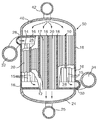
도 2는 도 1a의 반응기 블록을 포함하는 반응기 모듈의 단면도.
도 3은 본 발명의 반응기 모듈들을 포함하는 프로세스 플랜트의 일부의 흐름도. 1A is a cross-sectional view of a portion of a reactor block suitable for FT synthesis.
1B is a cross-sectional view of a portion of an alternative reactor block suitable for FT synthesis.
FIG. 2 is a cross-sectional view of a reactor module including the reactor block of FIG. 1A. FIG.
3 is a flow diagram of a portion of a process plant including reactor modules of the present invention.
본 발명은 천연 가스(기본적으로 메탄)를 장쇄 탄화수소들로 변환하기 위한 화학 공정에 관한 것이다. 이 공정의 제1단계는 합성 가스를 생성하는 것이며, 양호하게 스팀 개질화, 즉 아래 반응식을 포함한다. The present invention relates to a chemical process for converting natural gas (basically methane) into long chain hydrocarbons. The first step of this process is the generation of syngas and preferably comprises steam reforming, ie the reaction below.
[반응식 1]Scheme 1
H2O + CH4 -> CO + 3 H2
H 2 O + CH 4- > CO + 3 H 2
상기 반응은 흡열 반응이며, 제1유동 채널에서 로듐 또는 백금/로듐 촉매에 의하여 촉진될 수 있다. 이 반응을 일으키는데 필요한 열은 연료 가스, 즉 메탄, 또는 단쇄(short-chain) 탄화수소(예를 들어 에탄, 프로판, 부탄), 일산화탄소, 수소 또는 이 가스들의 혼합물을 연소시킴으로써 제공될 수 있으며, 상기 가스들은 발열성이고 그리고 인접한 제2유동 채널에서 팔라듐/백금 촉매에 의해 촉진될 수 있다. 대안으로서 합성 가스는 공지된 프로세스들인, 부분 산화 공정 또는 오토써말(autothermal) 프로세스에 의해 생성될 수 있으며, 이들은 약간 다른 구성물들의 합성 가스들을 생성한다. The reaction is an endothermic reaction and can be promoted by a rhodium or platinum / rhodium catalyst in the first flow channel. The heat required to cause this reaction can be provided by burning fuel gas, i.e. methane, or short-chain hydrocarbons (e.g. ethane, propane, butane), carbon monoxide, hydrogen or mixtures of these gases, Are exothermic and can be promoted by a palladium / platinum catalyst in an adjacent second flow channel. As an alternative, the synthesis gas can be produced by known processes, either partial oxidation processes or autothermal processes, which produce synthesis gases of slightly different compositions.
다음에 합성 가스 혼합물은 장쇄 탄화수소들을 발생하기 위해 FT 합성을 실행하는데 사용된다. 즉,The synthesis gas mixture is then used to perform FT synthesis to generate long chain hydrocarbons. In other words,
[반응식 2]Scheme 2
n CO + 2n H2 -> (CH2)n + n H2O
n CO + 2n H 2- > (CH 2 ) n + n H 2 O
상기 반응은 발열 반응이므로, 철, 코발트 또는 융합 마그네타이트(fused magnetite)와 같은 촉매의 존재하에, 통상적으로 190℃ 내지 280℃ 사이의 고온과, 1.8 MPa 내지 2.8 MPa(절대값들) 사이의 고압을 발생한다. FT 합성을 위한 양호한 촉매는 약 10-40% 코발트(알루미나에 비하여 중량당)와, 코발트의 중량보다 10% 작은, 루테늄, 백금 또는 가돌리늄과 같은 촉진제(promoter) 및 란타늄(lanthanum) 산화물과 같은 염기성 촉진제를 갖는, 140-230 m2/g 의 비표면적의 감마-알루미나의 코팅을 포함한다. 양호한 반응 조건들은 215℃ 내지 235℃ 사이의 온도와, 2.1 MPa 내지 2.7 MPa의 범위, 예를 들면, 2.6 MPa의 압력이다. Since the reaction is exothermic, high temperatures typically between 190 ° C. and 280 ° C. and high pressures between 1.8 MPa and 2.8 MPa (absolute values) are typically employed in the presence of a catalyst such as iron, cobalt or fused magnetite. Occurs. Preferred catalysts for FT synthesis are about 10-40% cobalt (per weight by weight of alumina) and basics such as lanthanum oxides and promoters such as ruthenium, platinum or gadolinium, 10% less than the weight of cobalt. And a coating of gamma-alumina of a specific surface area of 140-230 m 2 / g with an accelerator. Preferred reaction conditions are temperatures between 215 ° C. and 235 ° C. and pressures in the range of 2.1 MPa to 2.7 MPa, for example 2.6 MPa.
이제 도 1a를 참고하면, FT 반응기 모듈(50)(도 2 참조)에서 사용하기에 적절한 반응기 블록(10)이 도시되어 있고, 반응기 블록(10)은 단면이 일부분만 도시되어 있다. 반응기 블록(10)은 FT 합성을 위한 채널들(17)과 교호하는 냉각수 채널들(15)을 형성하기 위해 이격된 두께 1mm 의 평평한 플레이트들(12)의 스택으로 구성된다. 냉각수 채널들(15)은 평평한 상단의(flat-topped) 톱니 파형으로 형성된 두께 0.75 mm의 시트들(14)에 의해 형성된다. 이 파형의 높이는 (통상 1 내지 4 mm의 범위에서) 본 예의 경우 2 mm 이고, 따라서 두꺼운 중실(solid) 에지 스트립들(16)은 측면들을 따라 제공되고, 파형의 진폭은 12 mm 이다(이 배치는 이하에 상세히 설명된다). FT 합성을 위한 채널들(17)은 높이가 5 mm (통상 2 mm 내지 10 mm 범위 내에서)이고, 높이 5mm, 간격이 80 mm (이 간격은 통상 20 - 100 mm의 범위이다)인 정사각형 또는 직사각형 단면의 바들(18)에 의해 형성되고, 그리고 직선형 관통 채널들을 형성한다. FT 합성을 위한 각각의 채널들(17) 내에 있는 50 ㎛ 두께의 파형 포일(20)(통상 20-150 ㎛ 범위의 두께를 가진다)이 촉매 재료를 위한 지지체로서 작용하는 세라믹 코팅을 갖는다{단지 2개의 포일(20)만이 도시되어 있다}. 반응기 블록(10)은 채널들(15, 17)을 형성하는 컴포넌트들을 적층하고 다음에 이들을 예를 들어 용접 또는 확산 접합에 의하여 다함께 접합함으로써 제조될 수 있다. 다음에, 반응기 블록(10)은 채널들(15, 17)이 직립하도록 90°만큼 회전되고, 그리고 촉매 보유 포일들(20)이 채널들(17) 내로 삽입된다. Referring now to FIG. 1A, a
이제 도 1b를 참고하면, FT 반응기 모듈에서 사용하기에 적절한 대안의 반응기 블록(110)이 도시되어 있고, 반응기 블록(110)은 단면이 일부분만 도시되어 있다. 많은 관점에서 반응기 블록(110)은 반응기 블록(10)과 유사하며, 동일한 구성부품들은 동일한 참고부호로서 언급된다. 반응기 블록(110)은 FT 합성을 위한 채널들(117)과 교호하는 냉각수 채널들(15)을 형성하기 위해 이격된 두께 1mm 의 평평한 플레이트들(12)의 스택으로 구성된다. 냉각수 채널들(15)은 추가로 중실 에지 스트립들(16)을 가지며, 평평한 상단의 톱니 파형으로 형성된 두께 0.75 mm의 시트들(14)에 의해 형성된다. FT 합성을 위한 채널들(117)은 중실 에지 바들(18)에 의해 밀봉되고 그리고 4mm 내지 12 mm의 범위, 양호하게 5 mm 의 높이를 갖는 캐스텔레이션 형상으로 된 두께 1.0 mm 의 시트들(119)에 의해 추가로 형성된다. 양호한 실례로서 만들어진 채널들(117)은 폭이 10 mm, 높이 5 mm 이고, 그리고 한 면에서 대향한 면까지 스택을 통하여 일직선으로 연장된다. 반응기 블록(10) 내에 있는 채널들(15, 17)에서와 같이, 반응기 블록(110) 내의 채널들(15, 117)은 평행하게 연장한다. FT 합성을 위한 각각의 채널들(117) 내에서, 파형의 박막 포일(120)은 20 - 150 ㎛ 범위, 양호하게는 50 ㎛의 두께를 갖고, 동시에 촉매 재료를 위한 지지체로서 작용하는 세라믹 코팅을 갖는다{그와 같은 포일들(120)은 3개만 도시되어 있다}. 반응기 블록(110)은 채널들(15, 117)을 형성하는 컴포넌트들을 적층하고 다음에 이들을 예를 들어 용접에 의하여 다함께 접합함으로써 제조될 수 있다. 다음에 반응기 블록(110)은 채널들(15, 117)이 직립하도록 90°만큼 회전되고, 그리고 촉매 보유 포일들(120)이 채널들(117) 내로 삽입된다. Referring now to FIG. 1B, there is shown an
양쪽 반응기 블록들(10, 110)에서 촉매 인서트들(20 또는 120)이 채널(17 또는 117)의 높이를 갖는 단일 파형 포일로서 도시되어 있지만, 대신에 파형 포일들, 실질적으로 평평한 포일들의 스택으로 구성될 수 있다. 도 1b에 도시된 반응기 블록(110)에서 채널들(117)은 그들의 가장 큰 횡단 치수가 플레이트들(12)의 평면과 평행하다. 대안적인 배치로서(도시되지 않음), 채널들은 그들의 가장 큰 횡단 치수가 플레이트들(12)의 평면에 수직이 될 수 있다. 어느 경우에도 채널들의 폭은 양호하게 약 4 내지 20 mm 사이에 있다. 각 플레이트(12)는 예를 들어, 1.3 m × 1.3 mm, 또는 1.2 mm × 0.8 mm가 될 수 있고, 따라서 채널들(17 또는 117)은 각각 길이 1.3 mm, 또는 길이 0.8 mm가 될 것이다. 양호하게 채널들(17 또는 117)은 길이 1.5 mm 보다 작고, 양호하게는 적어도 길이 0.3 mm 이다. The catalyst inserts 20 or 120 in both reactor blocks 10, 110 are shown as a single corrugated foil with the height of the
이제 도 2를 참고하면, 반응기 블록(10)을 포함하는 반응기 모듈(50)은 수직 단면으로 도시되고, 반응기 블록(10)이 부분적으로 절단되어 있다. 상술한 바와 같이, 반응기 블록(10)은 유동 채널들(15, 17)을 형성하기 위해 서로 분리된 평평한 플레이트들(12)의 스택으로 구성된다. FT 반응을 위한 채널들(17)은 촉매 보유 파형 포일들(20)을 수용하고, 반응기 블록(10)을 통해 일직선으로 (상단에서 하단까지) 연장하고, 상단면은 개방되고, 하단면에서 채널들(17)은 헤더(24)와 소통한다. 반응 생성물들은 헤더(24)에서 나와 도관(25)을 통해 흐른다. 냉각수 채널들(1)을 위해 평평한 플레이트들(12)은 플레이트(12)의 주변 둘레에서 에지 스트립들(16)에 의하여 멀리 유지되고, 또한 파형 시트들(14)에 의해 중앙 섹션에서 유지된다. 각각의 파형 시트(14)의 각 단부를 지나는 단부 부분(26)은 한 측면에서 갭으로 떨어져서 에지 스트립들(16)에 의해 둘러싸이고, 따라서 단부 부분(16)은 각각의 헤더(28 또는 30)와 소통하고, 이들은 반응기 블록(110)의 길이로 연장하고 그리고 도시된 바와 같이 직경상으로 대향한 코너들 부근에 있는 측면들에서 상단이 좌측에 하단이 우측에 부착된다. 냉각수는 헤더(28)로 공급되고 헤더(30)를 통해 빠져나오고, 단부 부분들(26)은 헤더(28 또는 30)와 냉각수 채널들(15) 사이로 냉각수를 분배한다. 냉각수는 도관(32)으로부터 헤더(28)로 공급되고, 도관(34)에 의해 헤더(3)로부터 제거되고, 따라서 냉각수 흐름이 대체로 FT 채널들(17) 내의 흐름에 대해 병류가 된다. 평평한 플레이트들(12), 에지 스트립들(16), 바들(18), 및 파형 시트들(14)은 알루미늄 합금, 예로서 3003 그레이드(grade)(약 1.2% 망간 및 0.1% 구리를 갖는 알루미늄)로 제조될 수 있다. Referring now to FIG. 2, the
합성 가스는 헤더(40)를 통하여 반응기 블록(10)의 상단면으로 공급되지만, 다른 공급 수단이 반응기 블록(10)과 함께 사용될 수 있다는 것을 알게 될 것이다. 합성 가스는 파이프(42)를 통하여 헤더(40)로 공급된다. Synthesis gas is supplied through the
반응기 모듈(50)의 사용시에 냉각수는 냉각수 온도가 반응기(50)를 통과할 때 10 K와 같은 정도의 프리셋(preset) 양만큼 증가하는 그러한 유동률로 공급될 수 있으며; 냉각수를 FT 채널들(17)에 대해 병류 흐름이 되도록 배치하면 {분배 단부 부분(26) 내에서 냉각수 흐름으로부터 멀어지는} 반응기 블록(10)의 냉각 채널들을 통해 어떤 수평면에 있는 어떤 두 지점들을 횡단하는 온도 차이를 최소로 줄이는데 도움이 된다. In the use of the
예를 들어, 반응기 블록(10)은 전체 길이가 1 m 초과, 소위 8m 가 될 수 있고, 그 단면적은 플레이트들(12) 중 하나의 단면적과 같다. 반응기 블록(10)을 포함하는 반응기 모듈(50)은 25 톤 이하의 중량을 가질 수 있으며, 따라서 종래의 화물 취급 설비에 의해 취급될 수 있다. 반응기 모듈은 장쇄 탄화수소들을 약 32 m3/일(day)(200 배럴/일)를 생산하는 충분한 능력을 가질 수 있다. For example, the
FT 반응기 모듈(50)은 장쇄 탄화수소들을 얻기 위해 천연 가스를 가공하기 위한 플랜트의 일부를 형성하며, 상기 플랜트는 메탄으로부터 합성 가스를 형성하기 위한 수단과, 장쇄 탄화수소들을 발생하기 위해 상기 합성 가스를 FT 합성으로 처리하기 위한 수단을 포함한다. 이러한 프로세스는 예를 들어 관련된 가스를 처리하기 위해 유정에서 실행될 수 있다. 그러나, 관련된 가스의 유동률은 유정의 작동 수명을 통하여 중대한 변화가 있을 것으로 예상될 수 있고, 따라서 관련된 가스의 유동률의 변화 또는 변동을 수용할 수 있는 것이 필요하다. 이것은 이제 참고로 하는 도 3에 도시된 바와 같은 플랜트를 사용함으로써 달성될 수 있으며, 상술한 바와 같이 동일한 다수의 FT 반응기 모듈(50)들을 포함하고(단지 4개만 도시됨), 각 모듈은 합성 가스의 흐름들이 평행하게 연장되는 반응기 블록(10)을 포함하고, 따라서 가스 유동률의 변화들이 사용하고 있는 반응기들의 개수를 변화시킴으로써 수용될 수 있다. 따라서 스페이스 속도와 같은 FT 합성 반응 조건들은 관련된 가스의 유동률의 상당한 변화에도 불구하고 비교적 좁은 범위 내에서 유지될 수 있다. 예를 들어, 플랜트가 장쇄 탄화수소들을 150 m3/일의 용량만큼 생산할 필요가 있으면, 그때 플랜트는 위에서 지적한 치수들을 각각 갖는 동일한 5개의 반응기 모듈(50)들을 사용할 수 있으며, 따라서 각각의 반응기 모듈(50)은 32 m3/일의 용량을 가진다. The
적절한 압력에서의 합성 가스는 공급관(60)을 통해 제공되며, 상기 공급관을 통하여 합성 가스는 각 반응기 모듈(50)의 입구 파이프(42)로 공급된다. 냉각수는 냉각수 채널들을 통해 순환되며 그리고 온도제어 시스템(44)(개략적으로 도시됨)을 경유하여 재순환되고, 냉각수를 위한 입구(32)와 출구(34) 사이의 온도 차이가 소위 10 K 보다 작고, 그리고 반응기(50)의 평균 온도는 일정하게 유지된다는 것을 보장한다. 각 반응기 모듈(50)이 자신의 온도제어 시스템(44)을 구비하는 것으로 도시되어 있지만, 실제로 단일 온도제어 시스템이 보통 모든 모듈(50)들을 위해, 또는 모듈(50)들의 그룹들을 위해 제공되며; 그러나 반응기 모듈(50)이 개별적으로 변화된다면 그때 각 모듈(50)은 새로운 촉매와 오래된 촉매 사이의 활성의 변화를 수용하기 위하여 전용 제어부를 포함할 수 있다. Synthesis gas at an appropriate pressure is provided through
FT 반응기의 성능(예를 들어, CO의 % 변환율)은 반응 온도에 의존하는 것으로 알려져 있다. 그러나 상술한 바와 같은 반응기에서 반응기 채널들을 따라서 최대 10 K의 온도 차이는 중대한 영향을 미치지 않으며; 반응기의 성능은 평균 온도에 의해 결정되는 것을 알게 되었다. 따라서 온도 제어 시스템(44)은 평균 냉각수 온도가 예정된 변환율을 달성하도록 하는 값을 가지며 그리고 평균 온도가 설정점 값에서 2K 이상, 양호하게는 1 K 이상 차이가 나지 않도록 보장하기 위하여 제어회로를 포함한다. 이러한 제어는 반응기 모듈(50)로 공급되는 냉각수의 온도를 제어함으로써 달성되고, 평균 온도의 미세한 조정은 유동률을 조정함으로써 달성되는데, 왜냐하면 프로세스 측면에서의 입구와 출구 사이의 온도 차이가 냉각수 측면에서의 대응하는 온도 차이와 직접적으로 관련되어 있기 때문이다. 동시에 냉각수 유동률은 또한 유입하는 냉각수와 유출하는 냉각수 사이의 온도 차이가 프리셋 한계를 초과하지 않는다는 것을 보장하며; 상기 한계는 10 K 이하, 예를 들어 7 K 또는 5 K 가 될 수 있다. The performance of the FT reactor (eg% conversion of CO) is known to depend on the reaction temperature. However, the temperature difference of up to 10 K along the reactor channels in the reactor as described above has no significant effect; It was found that the performance of the reactor was determined by the average temperature. The
반응 생성물들을 함유하는 유체 혼합물은 FT 반응기 모듈(50)들로부터 도관(25)을 통해 배출되고, 수증기 및 장쇄 탄화수소들을 응축하기 위하여 열교환기(46)를 통과함으로써 냉각된다. 이것은 다음에 분리기(48)에 의해 물, 액체 탄화수소들 C5+, 및 나머지 테일 가스들(tail gases)(64)로 분리된다. 열교환기(46)를 위해 사용된 냉각수는 물이 될 수 있고, 대기 온도에서 소위 약 20 또는 30℃, 또는 양호하게는 열교환면들의 왁싱(waxing)이 없음을 보장하기 위해 다소 따뜻한, 즉 약 60 내지 80℃ 사이가 될 수 있다. The fluid mixture containing the reaction products is withdrawn from the
반응기 모듈들(50)과, 열교환기(46), 및 분리기(48)의 조합은 합성 조립체(66)로서 언급될 수 있다. 이때, 어떤 경우에 분리기(48)로부터의 테일 가스(64)는 나머지 수소 및 일산화탄소를 추가의 장쇄 탄화수소들 C5+로 변환하기 위해 제2 합성 조립체(66)를 통해 공급된다. 대체로 플랜트는 복수의 단계들로서 FT 합성을 실행하기 위해 그러한 합성 조립체(66)를 복수 개로서 구성될 수 있다. 단계들의 개수는 각 단계에서 FT 합성을 겪는 합성 가스의 비율에 의존한다. The combination of
이 플랜트에서 각각의 모듈(50)은 차단 밸브들(55) 또는 차단 밸브들(55)의 쌍들을 구비하며, 따라서 합성 가스의 유입 및 유출은 플랜트의 나머지 작동을 방해하지 않고 개별 반응기 모듈(50)에 대해 중단될 수 있다. 또한 밸브들(55)은 냉각수를 중단시킬 수 있다. 따라서 관련된 가스의 유동률이 변하면, FT 합성을 실행하기 위한 플랜트의 용량(capacity)은 사용되는 반응기 모듈(50)들의 수를 변화시킴으로써 대응하여 조정될 수 있다. FT 반응기 모듈(50)들 중 하나를 차단할 필요가 있을 때, 차단 밸브들(55)은 모두 폐쇄되고, 그러나 동시에 반응기 모듈(50)은 어떤 나머지 합성 가스를 제거하기 위해, 폐쇄 가스 공급부(58)로부터 FT 채널 작동 압력(이 실례에서는 2.6 MPa)에서 폐쇄 가스와 함께 방출된다(flushed through). 폐쇄 가스 공급부(58)는 차단 밸브들(59)(이것은 정상 폐쇄되어 있다)을 경유하여 각 반응기 모듈(50)에 연결되며, 그러나 단지 하나의 반응기 모듈(50)에 대한 연결만이 도시되어 있다. 합성 가스를 방출한 후에, 그때 반응기 모듈(50)은 차단 밸브들(59)을 또한 폐쇄시킴으로써 이 작동 압력에서 폐쇄된다. 폐쇄 가스는 촉매 반응에 참여하지 않는 가스이며, 따라서 실질적으로 반응기 내에서 추가의 촉매 활동을 방지한다. 적절한 가스들의 예를 들면 순수한 메탄, 탈황된(desulphrised) 천연 가스, 및 질소를 포함한다. Each
이러한 과정은 또한 사용하지 않는 동안에는 예를 들어 반응기 모듈(50)이 소비한 촉매를 교체하기 위해 재설비(refurbish)될 필요가 있는 경우에, 제거 및 교체될 수 있게 한다. 플랜트에서 제거되고 이어서 감압되었던 그러한 반응기 모듈(50)은 헤더(40)를 반응기 블록(10)으로부터 분리함으로써 용이하게 해체될 수 있음을 알 것이다. 다음에 촉매 보유 포일들(30)은 채널들(17)의 개방 단부들을 통해 빠져나올 수 있다. This process also allows removal and replacement of the
상술한 반응기 블록(10) 및 반응기 모듈(50)은 단지 실례에 불과하며, 본 발명의 범위 내에서 유지되는 동안 여러 가지 방법으로 변경될 수 있다는 것을 알 것이다. 예를 들어 플레이트들은 다른 형상 및 크기로 될 수 있고, 유동 채널들(15, 17, 또는 117)은 상술한 것과 다른 형상을 가질 수 있으며, 예로서 파형 시트(14)는 캐스텔레이션된 파형을 가질 수 있다. 촉매 구조체는 단일 파형 포일(20 또는 120)으로서 도시되어 있지만, 대신에 예를 들어 2개의 파형 포일들 사이에 평평한 포일을 갖거나 또는 3개의 파형 포일들 사이에 2개의 평탄부를 갖는 조립체가 될 수 있다. 또한 촉매 구조체는 채널(17 또는 117)의 전체 길이로 연장되거나, 또는 예를 들어 냉각수 채널(15)에 인접한 채널의 일부를 따라서만 연장될 수 있다. It will be appreciated that the
길이가 약 1 m 이상인 반응기 블록(10)에서는, 단일 헤더(24) 대신에 블록(10)의 길이를 따라 일련의 헤더들(24)을 제공하거나, 또는 블록(10)의 길이를 따라서 적절한 위치들에 도관(25)을 헤더(214)에 연결하는 것이 바람직하다. 이러한 옵션들은 또한 합성 가스 헤더(40), 냉각수 유입 헤더(28), 및 냉각수 유출 헤더(30)에도 적용한다. 대각선 방향에서 서로 마주하는 하나의 냉각수 유입 헤더(28)와 하나의 냉각수 유출 헤더(30)를 제공하는 대신에, 2개의 냉각수 유입 헤더(28)가 반응기 블록(10)의 상단에서 이웃하는 각 측면에 하나씩 있게 하고, 2개의 냉각수 유출 헤더(30)가 반응기 블록(10)의 하단에서 이웃하는 각 측면에 하나씩 있을 수 있다. In
Claims (12)
상기 반응기 블록은, 피셔-트롭쉬 합성을 거친 가스 혼합물인 제1유체와 냉각수인 제2유체를 각각 운반하기 위해, 상기 블록(10, 110) 내에서 교대로 배열된 복수의 제1 및 제2 유동 채널들(17, 117; 15)을 형성하는 플레이트들(12)의 스택을 포함하며,
상기 제1유동 채널들(17, 117)은 상기 반응기 블록(10, 110)의 상부면과 하부면 사이에서 대체로 수직방향으로 연장하고,
상기 제2유동 채널들(15)은 상기 제1유동 채널들(17, 117)의 방향과 대체로 평행한 방향으로 연장되고, 분배기 챔버들(26)을 통해 상기 반응기 블록(10, 110)의 하나 이상의 측면들에 있는 입구 및 출구 포트(28, 30)와 소통하고,
각각의 제1유동 채널(17, 117)은 금속 기판을 포함하는 제거식 가스-침투성 촉매 구조체(20, 120)를 수용하는, 반응기 모듈.As a reactor module 50 for Fisher-Tropsch synthesis comprising generally rectangular reactor blocks 10, 110,
The reactor block is a plurality of first and second alternately arranged in the blocks (10, 110) to convey a first fluid, which is a gas mixture through Fischer-Tropsch synthesis, and a second fluid, which is cooling water, respectively. A stack of plates 12 forming flow channels 17, 117; 15,
The first flow channels 17, 117 extend generally in a vertical direction between the top and bottom surfaces of the reactor blocks 10, 110,
The second flow channels 15 extend in a direction substantially parallel to the direction of the first flow channels 17, 117, and through the distributor chambers 26 one of the reactor blocks 10, 110. In communication with the inlet and outlet ports 28, 30 on the above side,
Each first flow channel (17, 117) contains a removable gas-penetrating catalyst structure (20, 120) comprising a metal substrate.
상기 플랜트는 제 1 항 내지 제 6 항 중 어느 한 항에 기재된 복수의 피셔-트롭쉬 반응기 모듈들(50)을 포함하고, 이 반응기 모듈들을 통해 합성 가스의 유동들이 평행하게 연장하여, 천연 가스 유동률의 변화들은 사용하고 있는 반응기 모듈들(50)의 수를 변경함으로써 수용될 수 있는, 플랜트.As a natural gas processing plant that obtains long chain hydrocarbons,
The plant comprises a plurality of Fischer-Tropsch reactor modules 50 according to any one of claims 1 to 6, through which the flows of syngas extend in parallel, thus providing a natural gas flow rate. Can be accommodated by changing the number of reactor modules 50 in use.
냉각수의 유동률은 반응기 모듈을 통과하는 냉각수의 온도 증가가 10 K 이하가 되도록 제어되는, 프로세스. A process for performing Fischer-Tropsch synthesis using the plant of claim 10,
The flow rate of the cooling water is controlled such that the temperature increase of the cooling water passing through the reactor module is less than or equal to 10 K.
The heat exchanger of claim 11, wherein the reaction products exiting from the Fischer-Tropsch reactor module 50 are heat exchanged with cooling water at an initial temperature in the range between 20 ° C. and 90 ° C., preferably between 50 ° C. and 80 ° C. 12. Process to pass (46).
Applications Claiming Priority (2)
| Application Number | Priority Date | Filing Date | Title |
|---|---|---|---|
| GBGB0725140.8A GB0725140D0 (en) | 2007-12-24 | 2007-12-24 | Catalytic Reactor |
| GB0725140.8 | 2007-12-24 |
Publications (1)
| Publication Number | Publication Date |
|---|---|
| KR20100101158A true KR20100101158A (en) | 2010-09-16 |
Family
ID=39048685
Family Applications (1)
| Application Number | Title | Priority Date | Filing Date |
|---|---|---|---|
| KR1020107016437A KR20100101158A (en) | 2007-12-24 | 2008-09-24 | Catalytic reactor |
Country Status (14)
| Country | Link |
|---|---|
| US (1) | US8444939B2 (en) |
| EP (1) | EP2227325B1 (en) |
| JP (1) | JP5571573B2 (en) |
| KR (1) | KR20100101158A (en) |
| CN (1) | CN101932379B (en) |
| AU (1) | AU2008339634B2 (en) |
| BR (1) | BRPI0821525A8 (en) |
| CA (1) | CA2708821C (en) |
| DK (1) | DK2227325T3 (en) |
| EA (1) | EA019964B1 (en) |
| GB (1) | GB0725140D0 (en) |
| MY (1) | MY157456A (en) |
| WO (1) | WO2009081175A1 (en) |
| ZA (1) | ZA201004401B (en) |
Cited By (2)
| Publication number | Priority date | Publication date | Assignee | Title |
|---|---|---|---|---|
| KR101297597B1 (en) * | 2011-04-19 | 2013-08-19 | 한국화학연구원 | Reactor system for producing hydrocarbons from synthetic gas |
| KR20180043065A (en) * | 2016-10-19 | 2018-04-27 | 주식회사 포스코건설 | Apparatus and method for manufacturing synthetic oil |
Families Citing this family (25)
| Publication number | Priority date | Publication date | Assignee | Title |
|---|---|---|---|---|
| AU2002349143A1 (en) * | 2001-12-05 | 2003-06-17 | GTL Mircosystems AG | Process an apparatus for steam-methane reforming |
| EA201070426A1 (en) * | 2007-10-02 | 2010-10-29 | КОМПАКТДЖТЛ ПиЭлСи | INSTALLATION ON OBTAINING SYNTHETIC LIQUID FUEL USING PARALLEL LINKS |
| GB0915036D0 (en) * | 2009-08-28 | 2009-09-30 | Compactgtl Plc | Catalytic reaction module |
| JP5581028B2 (en) * | 2009-09-16 | 2014-08-27 | 住友精密工業株式会社 | Catalytic reactor |
| KR101031886B1 (en) * | 2009-10-07 | 2011-05-02 | 한국에너지기술연구원 | Combination Type Cooling System for Elimination of Heat of Reaction AT Fischer-Tropsch Slurry Bubble Column Reactor |
| GB0918738D0 (en) * | 2009-10-26 | 2009-12-09 | Compactgtl Plc | Reactor with channels |
| GB201107070D0 (en) * | 2011-04-27 | 2011-06-08 | Davy Process Techn Ltd | FT process using can reactor |
| GB201112028D0 (en) * | 2011-07-13 | 2011-08-31 | Gas2 Ltd | Fixed bed fischer tropsch reactor |
| US11607657B2 (en) | 2012-02-06 | 2023-03-21 | Helbio S.A. | Heat integrated reformer with catalytic combustion for hydrogen production |
| US10961122B2 (en) * | 2012-02-06 | 2021-03-30 | Helbio S.A. | Heat integrated reformer with catalytic combustion for hydrogen production |
| WO2013123239A1 (en) | 2012-02-17 | 2013-08-22 | Ceramatec, Inc. | Advanced fischer tropsch system |
| CA2864519A1 (en) | 2012-02-21 | 2013-08-29 | Ceramatec, Inc. | Compact ft combined with micro-fibrous supported nano-catalyst |
| WO2013126341A1 (en) | 2012-02-21 | 2013-08-29 | Ceramatec, Inc. | Compact fischer tropsch system with integrated primary and secondary bed temperature control |
| JP2015517175A (en) | 2012-03-08 | 2015-06-18 | ヘルビオ ソシエテ アノニム ハイドロジェン アンド エナジー プロダクション システムズ | Catalytically heated fuel processor including a replaceable structured support for supporting a catalyst for a fuel cell |
| US9255746B2 (en) | 2012-10-26 | 2016-02-09 | Modine Manufacturing Company | Reactor core for use in a chemical reactor, and method of making the same |
| GB201302301D0 (en) * | 2013-02-08 | 2013-03-27 | Process Systems Entpr Ltd | Reactor and reaction method |
| US9676623B2 (en) | 2013-03-14 | 2017-06-13 | Velocys, Inc. | Process and apparatus for conducting simultaneous endothermic and exothermic reactions |
| JP6376131B2 (en) * | 2013-09-13 | 2018-08-22 | 株式会社Ihi | Reactor |
| CN106457186B (en) * | 2014-05-12 | 2019-12-03 | 尤尼威蒂恩技术有限责任公司 | System and method using having the plug-in package for stacking airflow clearance |
| US10543470B2 (en) | 2017-04-28 | 2020-01-28 | Intramicron, Inc. | Reactors and methods for processes involving partial oxidation reactions |
| US10544371B2 (en) | 2018-05-11 | 2020-01-28 | Intramicron, Inc. | Channel reactors |
| JP7271865B2 (en) * | 2018-05-17 | 2023-05-12 | 株式会社Ihi | Reactor |
| EP3599075A1 (en) * | 2018-07-27 | 2020-01-29 | Siemens Aktiengesellschaft | Reactor for carrying out a chemical equilibrium reaction |
| CN112221439A (en) * | 2020-09-09 | 2021-01-15 | 中石化宁波工程有限公司 | Distribution plate for microchannel reactor and microchannel reactor with distribution plate |
| CN113345611B (en) * | 2021-05-11 | 2022-12-13 | 哈尔滨工程大学 | Multi-rectangular-flow-channel uniform heat release simulation test device for plate-type fuel element |
Family Cites Families (11)
| Publication number | Priority date | Publication date | Assignee | Title |
|---|---|---|---|---|
| GB1116345A (en) * | 1964-06-16 | 1968-06-06 | Marston Excelsior Ltd | Improvements in or relating to chemical catalytic reactors and like process vessels in which fluids are contacted with solid materials |
| ZA782775B (en) * | 1977-06-27 | 1979-05-30 | Minnesota Mining & Mfg | Catalytic reactor for isothermal reactions |
| GB2223237B (en) * | 1988-07-21 | 1992-09-16 | Shell Int Research | Shut-down process for a fischer-tropsch reactor, and said reactor |
| GB0116894D0 (en) * | 2001-07-11 | 2001-09-05 | Accentus Plc | Catalytic reactor |
| GB0124999D0 (en) | 2001-10-18 | 2001-12-05 | Accentus Plc | Catalytic reactor |
| AU2002349143A1 (en) * | 2001-12-05 | 2003-06-17 | GTL Mircosystems AG | Process an apparatus for steam-methane reforming |
| BR0316828B1 (en) * | 2002-12-02 | 2013-04-24 | process and apparatus for performing a fischer-tropsch synthesis. | |
| GB0413400D0 (en) * | 2004-06-16 | 2004-07-21 | Accentus Plc | Catalytic plant and process |
| GB0501731D0 (en) * | 2005-01-31 | 2005-03-02 | Accentus Plc | Catalytic reactor |
| GB0504622D0 (en) * | 2005-03-05 | 2005-04-13 | Accentus Plc | Catalytic reactors |
| EP2384812A3 (en) * | 2006-05-08 | 2011-12-21 | CompactGTL plc | Rapid reactions in a compact catalytic reactor |
-
2007
- 2007-12-24 GB GBGB0725140.8A patent/GB0725140D0/en not_active Ceased
-
2008
- 2008-09-24 EP EP08806671.7A patent/EP2227325B1/en active Active
- 2008-09-24 BR BRPI0821525A patent/BRPI0821525A8/en active Search and Examination
- 2008-09-24 DK DK08806671.7T patent/DK2227325T3/en active
- 2008-09-24 US US12/810,128 patent/US8444939B2/en active Active - Reinstated
- 2008-09-24 MY MYPI2010002898A patent/MY157456A/en unknown
- 2008-09-24 KR KR1020107016437A patent/KR20100101158A/en not_active Application Discontinuation
- 2008-09-24 CA CA2708821A patent/CA2708821C/en active Active
- 2008-09-24 CN CN200880123322.8A patent/CN101932379B/en active Active
- 2008-09-24 EA EA201070797A patent/EA019964B1/en not_active IP Right Cessation
- 2008-09-24 JP JP2010540174A patent/JP5571573B2/en active Active
- 2008-09-24 WO PCT/GB2008/050855 patent/WO2009081175A1/en active Application Filing
- 2008-09-24 AU AU2008339634A patent/AU2008339634B2/en active Active
-
2010
- 2010-06-22 ZA ZA2010/04401A patent/ZA201004401B/en unknown
Cited By (2)
| Publication number | Priority date | Publication date | Assignee | Title |
|---|---|---|---|---|
| KR101297597B1 (en) * | 2011-04-19 | 2013-08-19 | 한국화학연구원 | Reactor system for producing hydrocarbons from synthetic gas |
| KR20180043065A (en) * | 2016-10-19 | 2018-04-27 | 주식회사 포스코건설 | Apparatus and method for manufacturing synthetic oil |
Also Published As
| Publication number | Publication date |
|---|---|
| BRPI0821525A8 (en) | 2016-03-22 |
| CA2708821C (en) | 2015-12-29 |
| DK2227325T3 (en) | 2014-06-30 |
| GB0725140D0 (en) | 2008-01-30 |
| AU2008339634A1 (en) | 2009-07-02 |
| CA2708821A1 (en) | 2009-07-02 |
| ZA201004401B (en) | 2011-08-31 |
| EP2227325A1 (en) | 2010-09-15 |
| EP2227325B1 (en) | 2015-01-07 |
| BRPI0821525A2 (en) | 2015-06-16 |
| AU2008339634B2 (en) | 2012-12-06 |
| US20100324158A1 (en) | 2010-12-23 |
| MY157456A (en) | 2016-06-15 |
| JP5571573B2 (en) | 2014-08-13 |
| WO2009081175A1 (en) | 2009-07-02 |
| CN101932379B (en) | 2014-06-04 |
| CN101932379A (en) | 2010-12-29 |
| US8444939B2 (en) | 2013-05-21 |
| EA201070797A1 (en) | 2010-12-30 |
| EA019964B1 (en) | 2014-07-30 |
| JP2011508043A (en) | 2011-03-10 |
Similar Documents
| Publication | Publication Date | Title |
|---|---|---|
| US8444939B2 (en) | Catalytic reactor | |
| US7235218B2 (en) | Catalytic reactors | |
| JP4446388B2 (en) | Catalytic reactor and method | |
| RU2296003C2 (en) | Catalytic reactor | |
| JP5001177B2 (en) | Catalytic reactor | |
| US10449506B2 (en) | Reactor and reaction system | |
| WO2014123152A1 (en) | Reactor | |
| US20040251001A1 (en) | Catalytic reactor | |
| TW200940164A (en) | Catalytic reaction module | |
| AU2010311190A1 (en) | Reactor with channels | |
| WO2014096779A1 (en) | Multi-channel chemical reactor | |
| KR20110110156A (en) | Chemical reactor operation | |
| US20120142789A1 (en) | Catalytic Reaction Module | |
| TW201039919A (en) | Catalytic reactor | |
| GB2441509A (en) | Fischer-Tropsch synthesis | |
| WO2013034934A1 (en) | Catalytic method using a plate-type reactor | |
| WO2013076460A1 (en) | Removal of carbon from a catalytic reaction module |
Legal Events
| Date | Code | Title | Description |
|---|---|---|---|
| A201 | Request for examination | ||
| E902 | Notification of reason for refusal | ||
| E601 | Decision to refuse application |