KR20100096217A - Method, system, integrated circuit, communication module, and computer-readable medium for achieving resource sharing including space and time reuse within a power line communication system - Google Patents
Method, system, integrated circuit, communication module, and computer-readable medium for achieving resource sharing including space and time reuse within a power line communication system Download PDFInfo
- Publication number
- KR20100096217A KR20100096217A KR1020107014536A KR20107014536A KR20100096217A KR 20100096217 A KR20100096217 A KR 20100096217A KR 1020107014536 A KR1020107014536 A KR 1020107014536A KR 20107014536 A KR20107014536 A KR 20107014536A KR 20100096217 A KR20100096217 A KR 20100096217A
- Authority
- KR
- South Korea
- Prior art keywords
- plc
- link
- information
- communication
- node
- Prior art date
Links
Images


Classifications
-
- H—ELECTRICITY
- H04—ELECTRIC COMMUNICATION TECHNIQUE
- H04B—TRANSMISSION
- H04B3/00—Line transmission systems
- H04B3/54—Systems for transmission via power distribution lines
- H04B3/544—Setting up communications; Call and signalling arrangements
-
- H—ELECTRICITY
- H04—ELECTRIC COMMUNICATION TECHNIQUE
- H04B—TRANSMISSION
- H04B2203/00—Indexing scheme relating to line transmission systems
- H04B2203/54—Aspects of powerline communications not already covered by H04B3/54 and its subgroups
- H04B2203/5404—Methods of transmitting or receiving signals via power distribution lines
- H04B2203/5408—Methods of transmitting or receiving signals via power distribution lines using protocols
-
- H—ELECTRICITY
- H04—ELECTRIC COMMUNICATION TECHNIQUE
- H04B—TRANSMISSION
- H04B2203/00—Indexing scheme relating to line transmission systems
- H04B2203/54—Aspects of powerline communications not already covered by H04B3/54 and its subgroups
- H04B2203/5429—Applications for powerline communications
- H04B2203/5445—Local network
Landscapes
- Engineering & Computer Science (AREA)
- Power Engineering (AREA)
- Computer Networks & Wireless Communication (AREA)
- Signal Processing (AREA)
- Cable Transmission Systems, Equalization Of Radio And Reduction Of Echo (AREA)
- Small-Scale Networks (AREA)
- Mobile Radio Communication Systems (AREA)
Abstract
통신 시스템은 단일망 또는 복수의 인접 망들이 리소소 공유는 증가시키고 상호간섭은 저감시키고 그들의 전체 스루풋은 증가시킬 수 있게 하는 통신 프로토콜들을 포함한다. 복수의 망들의 모든 전력선 통신(PLC) 디바이스들이 완전한 전력선 통신에 대하여 공통의 PHY(스펙, 신호 능력, 변조 방식, 코딩 방식, 대역폭 등)로 상호호환가능한 동질적인 망들과, 일부 PLC 망들의 디바이스들이 서로다른 망들의 디바이스들이 공통의 PHY를 사용하지 않는 완전한 전력선 통신에 대하여 다른 PLC 망들의 PLC 디바이스들과 상호호환할 수 없는 이질적인 망들에 다양한 프로토콜들이 적용된다. 이질적인 망들에 대하여, 복수의 이질적인 망들의 디바이스들 간의 리소스 공유를 가능하게 하는 망의 모든 디바이스들에 공통인 신호 방식을 통해 공존을 가능하게 하는 프로토콜이 제공된다. 동질적인 망들은 공통의 PHY를 이용하여 모든 노드들이 서로 통신할 수 있어 하나의 PLC 망에 관한 정보가 다른 PLC 망으로 전달될 수 있다. 이질적인 망들은, 예를 들어 서로다른 아파트 또는 주택내의 사용자들이 서로다른 스펙, 서로다른 신호 능력, 변조 방식, 코딩 방식, 대여폭 등을 갖는 서로다른 디바이스들을 이용하는 경우에 모든 PLC 망들이 그들 고유의 PHY를 이용하여 정보를 교환할 수 있는 것은 아니다.The communication system includes communication protocols that allow a single network or a plurality of neighboring networks to increase resource sharing, reduce interference and increase their overall throughput. All power line communication (PLC) devices in a plurality of networks are homogeneous networks compatible with a common PHY (spec, signal capability, modulation scheme, coding scheme, bandwidth, etc.) for complete power line communications, and devices in some PLC networks. Various protocols are applied to heterogeneous networks where devices in different networks are not compatible with PLC devices in other PLC networks for complete powerline communication without using a common PHY. For heterogeneous networks, a protocol is provided that enables coexistence through a signaling scheme common to all devices in a network that enables resource sharing between devices of a plurality of heterogeneous networks. In homogeneous networks, all nodes can communicate with each other using a common PHY so that information about one PLC network can be transferred to another PLC network. Heterogeneous networks, for example, if users in different apartments or houses use different devices with different specifications, different signal capabilities, modulation schemes, coding schemes, rental widths, etc., all PLC networks use their own PHY. It is not possible to exchange information.
Description
본 발명은 전력선 통신망에 관한 것이다.The present invention relates to a power line communication network.
전력선 케이블들은 거의 모든 가정과 회사에 보급되어 고객들에게 디지털 서비스들을 제공할 뿐만 아니라 LAN(Local Area Networking) 능력들을 제공하는 매우 유용한 기술을 제공하는 보급력 있는 매체이다. 하지만, 트위스트 페어 케이블들일 수 있는 전력선 케이블들은 공유 매체이기 때문에 오로지 특정 가입자에게만 전용된 링크들을 제공할 수는 없다. 구체적으로, 저전압 변환기에서 일련의 각 가정들 또는 일련의 다세대 거주시설까지 확장되는 전력선 케이블들은 일련의 사용자들 사이에서 공유된다. 이는, 한 아파트 또는 주택내의 한 사용자에 의해 발생된 신호들이 인접 아파트 또는 주택에서 발생된 신호들과 간섭될 수 있다는 것을 의미한다. 한 사용자에 의해 발생된 신호들을 국부적으로 포함하는 것은 불가능하기 때문에, 지리적으로 인접한 영역에서 전력선 통신(PLCs)을 사용하는 사용자들이 많을수록 발생되는 간섭도 많을 것이다. 간섭이 증가함에 따라, 보다 많은 패킷 충돌이 일어나기 때문에 모든 사용자가 데이터 전송 속도의 감소를 경험할 것이다.Powerline cables are a pervasive medium that is deployed in nearly every home and business to provide very useful technology that not only provides digital services to customers but also provides local area networking (LAN) capabilities. However, power line cables, which may be twisted pair cables, are a shared medium and thus cannot provide links dedicated solely to a particular subscriber. Specifically, power line cables that extend from a low voltage converter to a series of homes or a series of multi-family dwellings are shared among a series of users. This means that signals generated by a user in an apartment or house may interfere with signals generated in an adjacent apartment or house. Since it is impossible to include signals generated by one user locally, the more users using powerline communications (PLCs) in geographically adjacent areas, the more interference will be generated. As interference increases, more packet collisions will occur, so all users will experience a decrease in data transmission rate.
이 현상은 단일 망에서도 발생할 수 있다. 사실상, 망 내의 노드들의 개수가 증가할 수록 패킷 충돌 확률이 증가하여 단일 망의 전체 스루풋은 감소된다. 따라서, 많은 노드들 또는 복수의 망들이 존재하더라도 전체 망 스루풋을 증가시키는 궁극적인 목적으로 최적의 성능을 유지하기 위한 기술을 PLC 디바이스들에 제공하는 것이 바람직하다.This can happen even in a single network. In fact, as the number of nodes in the network increases, the probability of packet collisions increases, reducing the overall throughput of a single network. Thus, it is desirable to provide PLC devices with techniques for maintaining optimal performance for the ultimate purpose of increasing overall network throughput even if there are many nodes or multiple networks.
본 발명은 단일 망 또는 복수의 인접 망들이 상호 간섭을 줄이고 그들의 전체 스루풋을 증가시킬 수 있게 하는 프로토콜들을 제공한다. 이러한 프로토콜들은 두가지 케이스인 1) 복수의 망들의 모든 전력선 통신(PLC) 디바이스들이 완전한 전력선 통신에 대하여 공통의 PHY(변조 방식, 코딩 방식, 대역폭 등)로 상호호환될 수 있는 동질적인 망들과, 2) 일부 PLC 망들의 디바이스들이 서로다른 망들의 디바이스들이 공통의 PHY를 사용하지 않는 완전한 전력선 통신에 대하여 다른 PLC 망들의 PLC 디바이스들과 상호호환될 수 없는 이질적인 망들로 정의될 것이다. 이질적인 망들에 대하여, 복수의 이질적인 망들의 디바이스들 간의 리소스 공유를 가능하게 하는 단순한 신호 방식을 통해 공존을 가능하게 하는 프로토콜이 제공된다. The present invention provides protocols that allow a single network or a plurality of neighboring networks to reduce mutual interference and increase their overall throughput. These protocols include two cases: 1) homogeneous networks, in which all power line communication (PLC) devices in multiple networks can be interoperable with a common PHY (modulation scheme, coding scheme, bandwidth, etc.) for complete power line communications; Devices in some PLC networks will be defined as heterogeneous networks that are not compatible with PLC devices in other PLC networks for full powerline communication where devices in different networks do not use a common PHY. For heterogeneous networks, a protocol is provided that enables coexistence through a simple signaling scheme that enables resource sharing between devices of a plurality of heterogeneous networks.
동질적인 망들은 공통의 PHY를 이용하여 모든 노드들이 서로 통신할 수 있어 하나의 PLC 망에 관한 정보가 다른 PLC 망으로 전달될 수 있다. 이질적인 망들은 모든 PLC 망들이 그들 고유의 PHY를 이용하여 정보를 교환할 수 있는 것은 아닌 망들이다. 이는, 서로다른 아파트 또는 주택내의 사용자들이 다른 스펙, 다른 신호 능력, 변조 방식, 코딩 방식, 대여폭 등을 갖는 다른 디바이스들을 이용하는 경우이다.In homogeneous networks, all nodes can communicate with each other using a common PHY so that information about one PLC network can be transferred to another PLC network. Heterogeneous networks are not all PLC networks that can exchange information using their own PHY. This is the case when users in different apartments or houses use different devices with different specifications, different signal capabilities, modulation schemes, coding schemes, rental widths and the like.
여기에 사용된 용어 "TDMA 구조"의 의미는 도 19a 내지 25와 그 설명을 따른다는 것이다. 본 발명은 각 셀룰러 채널이 각각 복수의 타임 슬롯들로 이루어진 TDMU들(Time Division Multiplexing Units)로 분할되는 TDMA 구조를 이용한다(도 20 참조). 요약하면, 망 상태는 TDMU내의 소정의 TDMA 구조와 관련되어 있으며, TDMU내의 하나 이상의 타임 슬롯들이 시스템내의 둘 이상의 망들에 할당된다. 시스템에서 이용가능한 복수의 TDMA 구조들의 일예로서, 도 23은 각각이 서로다른 고유 신호 방식들 PHY-A, PHY-B 및 PHY-C를 갖는 3개 시스템들의 디바이스들의 필드들 b0 및 b1에서 알려진 망 상태 및 리소스 요건들과 관련되어 있는 패턴들 1-7(TDMA 구조들)을 나타낸다. TDMA 구조들은 망 내의 모든 디바이스들에 알려져 있으며, 메모리내에서 프리-세트되고, 또한 업데이트가 이용가능하면 다운로드될 수도 있다. The meaning of the term "TDMA structure" as used herein is to follow Figures 19A-25 and its description. The present invention uses a TDMA structure in which each cellular channel is divided into time division multiplexing units (TDMUs) each consisting of a plurality of time slots (see FIG. 20). In summary, the network state is associated with a given TDMA structure in the TDMU, where one or more time slots in the TDMU are assigned to two or more networks in the system. As an example of a plurality of TDMA structures available in a system, FIG. 23 is a network known in fields b0 and b1 of devices of three systems, each having different unique signaling schemes PHY-A, PHY-B and PHY-C. Patterns 1-7 (TDMA structures) that relate to state and resource requirements are shown. TDMA structures are known to all devices in the network, are preset in memory, and may also be downloaded if an update is available.
용어 QoS(quality of service)는 리소스 예약 제어 메커니즘을 의미한다. 일반적으로, QoS는 데이터 흐름을 소정 레벨의 성능으로 보장하거나 또는 서로다른 애플리케이션들, 사용자들, 또는 데이터 흐름들에 서로다른 우선순위를 제공하는 능력에 관한 것이다. QoS는, 예를 들면, 요구되는 비트 전송률, 신호 대 잡음비, 패킷 손실 확률 및/또는 비트 에러율에 기초할 수 있다. 예를 들면, QoS는 최소 레벨의 품질이 유지되는 것이 요구되는 보장된 스루풋일 수 있다. QoS 레벨들은 표준화 기구에 의해 표준화될 수 있다.The term quality of service (QoS) refers to a resource reservation control mechanism. In general, QoS relates to the ability to guarantee data flow at a certain level of performance or to give different applications, users, or different priorities to data flows. QoS may be based, for example, on the required bit rate, signal to noise ratio, packet loss probability and / or bit error rate. For example, QoS may be guaranteed throughput where minimum levels of quality are required to be maintained. QoS levels can be standardized by the standardization body.
본 발명에서, PLC는 예를 들어 인터넷을 액세스하기 위한 홈 네트워크에 사용될 수 있다. 이러한 환경에서, 원하는 QoS는 전형적으로 광대역 인터넷 액세스, 즉 고속 데이터 전송 인터넷 액세스를 달성하기에 충분하여야 한다. 이러한 데이터 전송속도는 전형적으로 64 kbit/s에서 최대 1.0 Mbit/s 범위에 있다. 하지만, 본 발명은 어떤 실제 수치적인 데이터 전송속도 또는 표준 또는 심지어는 광대역 또는 고속 데이터 전송 환경에 한정되지는 않는다. 충분한 QoS를 이루는 특정 데이터 전송속도는 본 발명이 이용되는 특정 용도에 따를 것이다.In the present invention, the PLC can be used for example in a home network for accessing the Internet. In such an environment, the desired QoS should typically be sufficient to achieve broadband Internet access, ie high speed data transfer Internet access. These data rates typically range from 64 kbit / s up to 1.0 Mbit / s. However, the present invention is not limited to any actual numerical data rate or standard or even wideband or high speed data transfer environment. The specific data rate to achieve sufficient QoS will depend on the particular application in which the present invention is used.
여기서, 용어 "특정 QoS를 만족"은 소정의 임계치에서 또는 소정의 임계치 보다 위로 QoS를 만족시키는 것을 의미한다. 예를 들면, 데이터 전송 임계치가 256 kbits/s 이면, 특정 QoS는 데이터 전송속도가 256 kbits/s 보다 높거나 또는 같은 경우에 만족된다. 용어 "특정 QoS를 수정"은 수신 신호의 수신 품질이 낮은 경우에 예를 들어 임계치를 예를 들어 낮은 데이터 전송속도(예를 들면, 64 kbit/s)로 바꾸는 것을 의미한다.Here, the term "satisfy a certain QoS" means satisfying a QoS at or above a predetermined threshold. For example, if the data transfer threshold is 256 kbits / s, then a particular QoS is satisfied if the data transfer rate is higher than or equal to 256 kbits / s. The term " modify specific QoS " means to change the threshold, for example to a low data rate (e.g. 64 kbit / s), for example when the reception quality of the received signal is low.
본 발명에 따르면, 많은 노드들 또는 복수의 망들이 존재하더라도 전체 망 스루풋을 증가시키는 궁극적인 목적으로 단일 망 또는 복수의 인접 망들이 상호간섭을 줄이고 그들의 전체 스루풋을 증가시키고 최적의 성능들을 유지할 수 있게 하는 프로토콜들이 제공될 수 있다.According to the present invention, even if there are many nodes or a plurality of networks, a single network or a plurality of neighboring networks can reduce the interference, increase their overall throughput and maintain optimal performances for the ultimate purpose of increasing the total network throughput. Protocols may be provided.
도 1a는 4개의 망 노드 디바이스들(하나의 마스터 M과 세개의 슬레이브들 x,y,z)로 구성된 전력선 통신(PLC) 망을 나타낸 도면이다.
도 1b는 고속 송신 전력 Pmax(y,z)를 이용하여 가능한 최대 데이터 전송속도로 노드 z로 송신하는 노드 y를 위한 링크의 IF(interference footprint)를 나타낸 도면이다.
도 1c는 Pmax(y,z) 보다 낮은 전력 Pmed(y,z)로 노드 z로 송신하는 노드 y의 링크를 위한 IF를 나타낸 도면이다.
도 1d는 Pmed(y,z) 보다 낮은 전력 Plow(y,z)로 노드 z로 송신하는 노드 y의 IF를 나타낸 도면이다.
도 2는 도 1a에 나타낸 모든 슬레이브 노드들에 도달하는데 필요한 최소 송신 전력 Pmin으로 비콘 신호를 송신하는 마스터 M를 나타낸 도면이다.
도 3은 망 내의 나머지 노드들 y 및 z에 도달하기 위해 최소 전력을 사용하도록 도 2에 나타낸 것에 대하여 전력을 저감시키는 마스터 M를 나타낸 도면이다.
도 4a는 노드 x가 최대 송신 전력 Pmax로 노드 y와 통신하는 링크를 나타낸 도면이다.
도 4b는 최소 송신 전력 Pmin(x,y)를 적용할 때 노드 x의 작은 IF를 나타낸 도면이다.
도 4c는 노드 x 및 y가 통신하는 시간에 통신하는 노드 z 및 w를 나타낸 도면이다.
도 4d는 Pmin(w,z)>Pack(z,w) 및 Pmin(x,y)>Pack(y,x)에 대한 IF를 나타낸 도면이다.
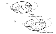
도 5a는 두개의 동시 액티브 링크들(x→y,w→z)을 나타낸 도면이다.
도 5b는 타임 슬롯 TS(1)에서 IFmin(x,y) 및 IFmin(w,z)를 발생시키는 링크들(x→y,w→z)과 타임 슬롯 TS(2)에서 IFmin(a,b)를 발생시키는 링크(a→b)를 나타낸 도면이다.
도 6은 망 1이 마스터 M1에 의해 한정되고 노드들{a,b,c}을 포함하고 망 2가 마스터 M2에 의해 한정되고 노드들{x,y,z,w}을 포함하는 시스템을 나타낸 도면이다.
도 7은 링크 b→c에 대한 전력 저감에 의해 노드 w가 IF(b,c)에 포함되지 않아 노드 w가 망 2 내의 어떠한 노드로부터도 신뢰성있게 데이터를 수신할 수 있는 도 6의 개선을 나타낸 도면이다.
도 8은 링크 M2→w가 간섭링크 b→c와 공존할 수 있는 도 6의 개선을 나타낸 도면이다.
도 9는 링크 w→x가 노드 b를 방해하지만 노드 b가 간섭링크의 마스터 M2와 직접 통신할 수 없는 도 6의 개선을 나타낸 도면이다.
도 10은 하나의 마스터와 세개의 슬레이브 노드를 갖는 독립된 시스템에 대한 망과 MNC(matrix of node connectivity)를 나타낸 도면이다.
도 11은 인접하는 AS들(autonomous systems) AS1 및 AS2를 나타낸 도면이다.
도 12a는 S=6 TDM(time division multiplexing) TEU들(elementary units)이 있고 액티브 링크들이 없는 경우에 도 10의 토폴로지에 대한 MTA(matrix of time allocations)를 나타낸 도면이다.
도 12b는 노드들 y 및 z가 TEUs #1 및 #2에서의 송/수신(TX/RX)이 금지되었다는 것을 나타내기 위해 엘리먼트들 MTA(y,1), MTA(y,2), MTA(z,1), MTA(z,2)이 1로 세트된 것을 나타낸 도면이다.
도 12c는 목적지 로우(로우 z)에서 MNC를 스캐닝하는 TX-금지가 마킹된 것을 나타낸 도면이다.
도 12d는 소스 로우(로우 y)에서 MNC를 스캐닝하는 RX-금지가 마킹되었다는 것을 나타낸 도면이다.
도 13a는 도 11의 노드 x가 노드 z와의 링크 설정을 요구하는 예에 대한 MTA를 나타낸 도면이다.
도 13b는 링크 a→b가 설정된 예에 대한 MTA를 나타낸 도면이다.
도 14a는 도 11에 나타낸 시스템에서 노드 x가 링크 x→z에 대한 2 TEU들을 요구할 때 4 성분 STR 프로토콜의 단계 3 완료시의 MTA를 나타낸 도면이다.
도 14b는 4 성분 STR 프로토콜의 단계 4 완료시의 도 14a의 MTA를 나타낸 도면이다.
도 15a는 도 14b에 나타낸 MTA를 갖는 시스템에서 노드 a가 링크 a→b에 대한 1 TEU를 요구할 때 4 성분 STR 프로토콜의 단계 3의 완료시의 MTA를 나타낸 도면이다.
도 15b는 4 성분 STR 프로토콜의 단계 4의 완료시의 도 15a의 MTA를 나타낸 도면이다.
도 16a는 도 15b에 나타낸 MTA를 갖는 시스템에서 노드 d가 링크 d→c에 대한 1 TEU를 요구할 때 4 성분 STR 프로토콜의 단계 3의 완료시의 MTA를 나타낸 도면이다.
도 16b는 4 성분 STR 프로토콜의 단계 4의 완료시의 도 16a의 MTA를 나타낸 도면이다.
도 17a는 도 16b에 나타낸 MTA를 갖는 시스템에서 마스터 M1이 링크 M1→w에 대한 1 TEU를 할당할 때 4 성분 STR 프로토콜의 단계 3의 완료시의 MTA를 나타낸 도면이다.
도 17b는 4 성분 STR 프로토콜의 단계 4의 완료시의 도 17a의 MTA를 나타낸 도면이다.
도 18은 서로다른 고유 신호 방식 PHY-A, PHY-B, 및 PHY-C를 갖는 세 시스템들의 디바이스들이 각 S-CSS들을 송신하는 예를 나타낸 도면이다.
도 19a는 세개의 서로다른 고유 신호 방식들의 존재를 나타내는 세개의 S-CSS 파형들의 검출을 나타낸 도면이다.
도 19b는 세개의 S-CSS 파형들 중 단 두개만이 검출된 도 19a의 개선을 나타낸 도면이다.
도 20은 연속적인 S-CSS 송신이 U TDM 유닛들(TDMUs)로 더 세분화되고 각 TDMU가 S TDM 슬롯들(TDMS)로 세분화된 실시예를 나타낸 도면이다.
도 21은 S=12 타임 슬롯들을 갖는 TDMA(time division multiple access) 구조를 나타낸 도면이다.
도 22는 S=12 타임 슬롯들을 갖는 두개의 TDMA 구조를 나타낸 도면이다.
도 23, 24 및 25는 두개의 S-CSS 송신 기회 윈도우들(필드들 b0 및 b1)이 리소스 요건들을 알리는데 사용되는 경우의 S=12 및 P=3에 대한 TDMA 구조들을 나타낸 도면이다.
도 26은 통신을 직교화하기 위해 시간 공유를 이용하는 두개의 이질적인 시스템들을 나타낸 도면이다.
도 27a는 서로 간섭되는 세개의 서로다른 PHY들을 갖는 세개의 시스템들을 나타낸 도면이다.
도 27b는 도 27a의 PHY-C를 이용하는 시스템의 노드들에 의해 발생된 공존 PHY 리스트(CPL)를 나타낸 도면이다.
도 27c는 도 27b의 CPL에 대한 UST(usable slot table)을 나타낸 도면이다.
도 28a 및 28b는 하나는 PHY-B를 이용하고 나머지 하나는 PHY-C를 이용하는 두개의 AS를 나타낸 도면이다.
도 29a는 도 28a 및 28b의 이질적인 시스템들에 대하여 시스템 B의 각 노드가 IIV(interference index vector)를 마스터 Mw에 보고하는 것을 나타낸 도면이다.
도 29b는 노드들 x, y, 및 z로부터 수신된 IIV들을 기초로 마스터 Mw에 의해 발생된 CPL을 나타낸 도면이다.
도 29c는 신호, 예를 들어 비콘을 통해 노드들 x, y, 및 z로 발생된 CPL를 브로드캐스트하는 마스터 Mw을 나타낸 도면이다.
도 29d는 노드들 Mw, x, y, 및 z의 IIV들에 따라 선택된 TDM 패턴들을 나타낸 도면이다.
도 30a 및 30b는 노드들 x, y, 및 z가 IPP{b0,b1} = {1,0}을 송신하고 Mw가 {1,1}을 송신하고 시스템 C의 노드들이 수신된 IPP들로부터 IIV들 = {B,C,A}를 생성하는 도 28의 이질적인 시스템들을 나타낸 도면이다.
도 30c는 노드들 a, b, 및 c로부터 수신된 IIV들을 기초로 마스터 Mo에 의해 발생된 CPL을 나타낸 도면이다.
도 30d는 노드들 Mo, a, b, 및 c의 IIV들에 따라 선택된 TDM 패턴들을 나타낸 도면이다.
도 31a는 링크 x ↔ z 및 링크 a ↔ b가 설정된 도 28a의 이질적인 시스템들을 나타낸 도면이다.
도 31b는 통신을 위해 노드들 x 및 z에 의해 선택된 TDM 패턴들을 나타낸 도면이다.
도 31c는 통신을 위해 노드들 a 및 b에 의해 선택된 TDM 패턴들을 나타낸 도면이다.
도 31d는 링크 x ↔ y 및 링크 a ↔ c가 설정된 도 28a의 이질적인 시스템들을 나타낸 도면이다.
도 31e는 통신을 위해 노드들 x 및 y에 의해 선택된 TDM 패턴들을 나타낸 도면이다.
도 31f는 통신을 위해 노드들 a 및 c에 의해 선택된 TDM 패턴들을 나타낸 도면이다.
도 32는 전력 제어를 통해 STR을 얻기 위한 방법을 나타낸 도면이다.
도 33은 MNC/MTA를 이용하여 STR을 얻기 위한 방법을 나타낸 도면이다.
도 34는 이질적인 망들에서 STR을 얻기 위한 방법을 나타낸 도면이다.
도 35a 및 35b는 MNC/MTA STR 프로토콜을 나타낸 도면이다.
도 36은 이질적인 PHY들에 대한 STR 프로토콜을 나타낸 도면이다.
도 37a는 PLC 전력 제어 장치를 나타낸 도면이다.
도 37b는 도 37a의 PLC 전력 제어 장치를 포함하는 집적회로를 갖는 PLC 집적회로 모듈을 나타낸 도면이다.
도 38a는 통신 채널을 할당하기 위한 STR 장치를 나타낸 도면이다.
도 38b는 도 38a의 STR 장치를 포함하는 집적회로를 갖는 STR 집적회로 모듈을 나타낸 도면이다.
도 39a는 통신 채널을 망 노드에 할당하는 STR 장치를 나타낸 도면이다.
도 39b는 도 39a의 STR 장치를 포함하는 집적회로를 갖는 STR 집적회로 모듈을 나타낸 도면이다.
도 40은 이질적인 PHY들에 대한 STR 프로토콜을 나타낸 도면이다.1A is a diagram illustrating a power line communication (PLC) network consisting of four network node devices (one master M and three slaves x, y, z).
FIG. 1B is a diagram illustrating an interference footprint (IF) of a link for node y transmitting to node z at the maximum possible data rate using fast transmit power P max (y, z).
1C is a diagram illustrating an IF for a link of node y transmitting to node z with a power P med (y, z) lower than P max (y, z).
FIG. 1D illustrates the IF of node y transmitting to node z at a power P low (y, z) lower than P med (y, z).
FIG. 2 is a diagram illustrating a master M for transmitting a beacon signal at the minimum transmit power P min required to reach all slave nodes shown in FIG. 1A.
FIG. 3 is a diagram illustrating a master M for reducing power relative to that shown in FIG. 2 to use minimum power to reach the remaining nodes y and z in the network.
4A illustrates a link in which node x communicates with node y at maximum transmit power P max .
4B is a diagram illustrating a small IF of node x when applying the minimum transmit power P min (x, y).
4C is a diagram illustrating nodes z and w communicating at times when nodes x and y communicate.
4d is a diagram showing IF for P min (w, z)> P ack (z, w) and P min (x, y)> P ack (y, x).
5A shows two simultaneous active links (x → y, w → z).
5b shows links (x → y, w → z) that generate IF min (x, y) and IF min (w, z) in time slot TS (1) and IF min (in time slot TS (2)). It is a figure which shows the link (a → b) which produces a and b.
6 shows a system in which
FIG. 7 illustrates the improvement of FIG. 6 in which node w is not included in IF (b, c) due to power reduction for link b → c so that node w can reliably receive data from any node in
FIG. 8 shows an improvement of FIG. 6 in which link M2 → w may coexist with interference link b → c.
FIG. 9 shows an improvement of FIG. 6 where link w → x interferes with node b but node b cannot communicate directly with master M2 of the interfering link.
FIG. 10 is a diagram illustrating a network and matrix of node connectivity (MNC) for an independent system having one master and three slave nodes.
FIG. 11 is a diagram illustrating adjacent autonomous systems AS1 and AS2.
FIG. 12A illustrates the matrix of time allocations (MTA) for the topology of FIG. 10 in the case of S = 6 time division multiplexing (TDM) elementary units (TEUs) and no active links.
12B shows elements MTA (y, 1), MTA (y, 2), MTA ( z, 1) and MTA (z, 2) are set to one.
12C is a diagram illustrating TX-inhibited scanning of the MNC in the destination row (row z).
FIG. 12D shows that the RX-Prohibit scanning the MNC at the source row (row y) is marked.
FIG. 13A is a diagram illustrating an MTA for an example in which node x of FIG. 11 requests to establish a link with node z.
13B is a diagram illustrating an MTA for an example in which link a → b is set.
FIG. 14A is a diagram illustrating an MTA upon completion of
FIG. 14B shows the MTA of FIG. 14A upon completion of
FIG. 15A shows the MTA upon completion of
FIG. 15B shows the MTA of FIG. 15A upon completion of
FIG. 16A shows the MTA at the completion of
FIG. 16B shows the MTA of FIG. 16A upon completion of
FIG. 17A is a diagram illustrating an MTA upon completion of
17B shows the MTA of FIG. 17A upon completion of
18 shows an example in which devices of three systems having different inherent signaling schemes PHY-A, PHY-B, and PHY-C transmit respective S-CSSs.
19A is a diagram illustrating the detection of three S-CSS waveforms indicating the presence of three different unique signal schemes.
19B illustrates the improvement of FIG. 19A in which only two of the three S-CSS waveforms are detected.
20 illustrates an embodiment in which consecutive S-CSS transmissions are further subdivided into U TDM units (TDMUs) and each TDMU is subdivided into S TDM slots (TDMS).
21 illustrates a time division multiple access (TDMA) structure with S = 12 time slots.
22 shows two TDMA structures with S = 12 time slots.
23, 24 and 25 are diagrams illustrating TDMA structures for S = 12 and P = 3 when two S-CSS transmission opportunity windows (fields b0 and b1) are used to inform resource requirements.
FIG. 26 illustrates two heterogeneous systems using time sharing to orthogonalize communication.
27A shows three systems with three different PHYs interfering with each other.
FIG. 27B is a diagram illustrating a coexistence PHY list (CPL) generated by nodes of a system using the PHY-C of FIG. 27A.
FIG. 27C illustrates a usable slot table (UST) for the CPL of FIG. 27B.
28A and 28B illustrate two ASs, one using PHY-B and the other using PHY-C.
FIG. 29A is a diagram illustrating that each node of system B reports an interference index vector (IIV) to the master Mw for the heterogeneous systems of FIGS. 28A and 28B.
FIG. 29B illustrates CPL generated by the master Mw based on IIVs received from nodes x, y, and z.
FIG. 29C is a diagram illustrating a master Mw that broadcasts a CPL generated to nodes x, y, and z via a signal, eg, beacon.
29D is a diagram illustrating TDM patterns selected according to IIVs of nodes Mw, x, y, and z.
30A and 30B show IIV from IPPs where nodes x, y, and z transmit IPP {b0, b1} = {1,0} and Mw transmits {1,1} and nodes of system C are received. Figure 2 shows the heterogeneous systems of FIG. 28 producing {B, C, A}.
FIG. 30C is a diagram illustrating CPL generated by the master Mo based on IIVs received from nodes a, b, and c.
30D is a diagram illustrating TDM patterns selected according to IIVs of nodes Mo, a, b, and c.
FIG. 31A illustrates the heterogeneous systems of FIG. 28A with links x ↔ z and links a ↔ b.
31B is a diagram illustrating TDM patterns selected by nodes x and z for communication.
31C is a diagram illustrating TDM patterns selected by nodes a and b for communication.
FIG. 31D illustrates the heterogeneous systems of FIG. 28A with link x ↔ y and link a ↔ c established.
31E is a diagram illustrating TDM patterns selected by nodes x and y for communication.
FIG. 31F is a diagram illustrating TDM patterns selected by nodes a and c for communication. FIG.
32 illustrates a method for obtaining a STR through power control.
33 is a diagram illustrating a method for obtaining an STR using MNC / MTA.
34 illustrates a method for obtaining STRs in heterogeneous networks.
35A and 35B illustrate the MNC / MTA STR protocol.
36 shows an STR protocol for heterogeneous PHYs.
37A is a diagram illustrating a PLC power control device.
FIG. 37B illustrates a PLC integrated circuit module having an integrated circuit including the PLC power control device of FIG. 37A.
38A illustrates an STR apparatus for allocating a communication channel.
FIG. 38B illustrates a STR integrated circuit module having an integrated circuit including the STR device of FIG. 38A.
FIG. 39A illustrates an STR apparatus for allocating a communication channel to a network node. FIG.
FIG. 39B illustrates a STR integrated circuit module having an integrated circuit including the STR device of FIG. 39A.
40 shows an STR protocol for heterogeneous PHYs.
이하, 본 발명의 바람직한 실시예를 첨부한 도면을 참조하여 상세히 설명한다. 첨부한 도면과 관련된 다음의 설명을 참조하면 본 발명의 특징, 개념, 목적, 및 장점들이 이 기술분야의 당업자에게 보다 명백해질 것이다. 다음의 설명은 본 발명의 바람직한 실시예들을 설명하기 위해 제공되었으며, 여기에 나타낸 특별한 특징들 및 상세들은 본 발명의 다양한 실시예들의 비한정 예시일 뿐이다. 특별한 특징들 및 상세들이 본 발명의 원리들 및 개념 해석을 가장 유용하고 쉽게 이해되는 설명이라고 생각되는 것을 제공할 목적으로 제공되었다. 이와 관련하여, 본 발명의 기본적인 이해를 위해 필요한 것보다 상세히 본 발명의 구조적인 상세를 나타내지는 않는다. 첨부한 도면들과 관련된 상세한 설명은 본 발명의 몇가지 형태들이 실제로 어떻게 실시될 수 있는지를 이 기술분야의 당업자에게 명백하게 하기 위한 것이다.Hereinafter, with reference to the accompanying drawings, preferred embodiments of the present invention will be described in detail. The features, concepts, objects, and advantages of the present invention will become more apparent to those skilled in the art with reference to the following description in conjunction with the accompanying drawings. The following description has been provided to explain preferred embodiments of the invention, and the specific features and details shown herein are merely non-limiting examples of various embodiments of the invention. Specific features and details have been provided for the purpose of providing what is believed to be the most useful and easily understood description of the principles and concepts of the present invention. In this regard, the structural details of the invention are not shown in more detail than necessary for a basic understanding of the invention. The detailed description with reference to the accompanying drawings is intended to clarify to those skilled in the art how some aspects of the invention may be practiced.
전력선 케이블들이 서로 다른 사용자들에게 공유 통신 채널을 제공하더라도, 동일한 망 또는 다른 망내의 다른 디바이스들로 한 디바이스에 의해 발생되는 간섭 레벨은 많은 팩터들, 예를 들어 송신 전력, 전력선 배선의 토폴로지(케이블 유형, 길이, 브리지 탭의 존재 및 개수, 망에 연결된 전기기구 등), 그라운딩 프랙티스, 주택으로 전달된 주상들의 개수, 디바이스들 간의 거리 등에 의존하는 확률 변수이다. 어떤 경우에, 전력선 통신(PLC) 디바이스들은 먼 곳에 위치하는, 예를 들어 다른 층에 위치하는 디바이스들 보다 공간적으로 인접한 다른 디바이스들과 더 간섭된다. 다른 경우에, 동일한 아파트내에 있더라도, 디바이스들이 예를 들어 동상의 AC 메인에 위치하는 지에 따라 매우 다른 간섭 레벨을 발생시킬 수 있다.Although power line cables provide a shared communication channel to different users, the level of interference generated by one device to other devices in the same or different networks may be affected by many factors, e.g. transmission power, topology of power line wiring (cables). Type, length, presence and number of bridge taps, electrical appliances connected to the network, etc.), grounding practices, the number of poles delivered to the house, and the distance between the devices. In some cases, power line communication (PLC) devices are more interfering with other spatially adjacent devices than devices located remotely, for example, located on another floor. In other cases, even if they are in the same apartment, they may generate very different interference levels depending on whether they are located, for example, in the AC mains of the statue.
본 발명은 동일한 망 또는 서로다른 인접 망들내에 있는 디바이스들이 서로 간섭을 일으키지 않고 동시에 송신할 수 있도록 STR(space and time reuse)을 수행하는 능력을 도입함으로써 전력선 채널의 특성들을 이용한다. 현재, 지금까지 알려진 PLC 시스템은 이러한 능력을 갖고 있지 않다. 동일한 망 내에서, 노드들에 직교 리소스들이 할당되거나(예를 들면, 서로다른 TDMA 슬롯들) 또는 리소스들을 경쟁(예를 들면, CSMA)시킨다. 현재, 지금까지 알려진 시스템들에서, 조화가 시도되지 않거나 또는 매우 작은 정보가 상호호환 디바이스들을 갖는 서로다른 망들 간에 공유되었다. 더욱이, 비 상호호환 디바이스들로 구성된 망들을 조화시키기 위한 해결책이 지금까지 알려진 시스템에서는 없었다.The present invention exploits the characteristics of powerline channels by introducing the ability to perform space and time reuse (STR) so that devices in the same network or in different adjacent networks can transmit simultaneously without interfering with each other. Currently, PLC systems known to date do not have this capability. Within the same network, orthogonal resources are allocated to nodes (eg, different TDMA slots) or contention (eg, CSMA) resources. Currently, in systems known to date, no coordination has been attempted or very little information has been shared between different networks with interoperable devices. Moreover, there has been no solution in the known systems to harmonize networks of incompatible devices.
전체 망 스루풋을 증가시키기 위해 STR을 위한 몇가지 프로토콜들이 여기에 제공된다. 동일한 망내의 디바이스들간 또는 서로다른 망들 간에 공유되어야 하는 정보량에 따라, 이들 프로토콜들은 독립적으로 또는 결합하여 구현되며 또한 서로다른 정도의 망 스루풋을 제공할 수 있다. Several protocols for STRs are provided here to increase overall network throughput. Depending on the amount of information to be shared between devices in the same network or between different networks, these protocols may be implemented independently or in combination and may also provide different degrees of network throughput.
이들 프로토콜들에 의해 이용되는 PLC 채널의 특성은 전력선 채널의 브로드캐스트 특성이다. 노드 i가 노드 j로 송신되면, 범위내의 다른 모든 노드는 노드 i에 의해 전달된 데이터 패킷을 수신한다. 따라서, 범위내의 어떤 노드 k는 i에 의해 송신된 패킷의 적어도 구분자(즉, 프리앰블 및 프레임 제어 정보)를 검출할 수 있으며, 따라서 (1) 링크의 소스 및 목적지 어드레스(SA/DA)(i의 SA 및 j의 DA) 및 (2) k에서 i에 의해 발생된 간섭 레벨을 알 수 있다.The characteristic of the PLC channel used by these protocols is the broadcast characteristic of the powerline channel. If node i is sent to node j, all other nodes in range receive the data packet delivered by node i. Thus, any node k in range can detect at least the delimiter (i.e. preamble and frame control information) of the packet sent by i, thus (1) the source and destination addresses (SA / DA) of i (i) The interference level generated by i in the DA of SA and j) and (2) k can be known.
동질적인 망에서, 망내의 모든 디바이스들은 상호 호환되며, 따라서, 데이터를 교환할 수 있다. 이러한 능력은 인접 망들에 속하는 디바이스들 간의 메시지 교환을 위해 디바이스 상호호환성을 이용하는 효율적인 STR 프로토콜들을 제공한다.
In a homogeneous network, all devices in the network are compatible with each other and thus can exchange data. This capability provides efficient STR protocols that use device interoperability for message exchange between devices belonging to neighboring networks.
(전력제어를 기반으로 한 STR 프로토콜)(STR protocol based on power control)
STR 전력 제어 프로토콜은 지금까지 알려진 PLC 시스템들에서는 구현되지 못했다. 이러한 지금까지 알려진 시스템들은 항상 노드들이 가까이 인접되어 있더라도 법적 제약에 의해 허용된 최대 전력으로 송신한다. 따라서, 인접 디바이스들 또는 망들에서 발생된 간섭은 종종 다른 디바이스들의 통신을 방해함으로써, 망내의 전체 스루풋을 저감시킨다.The STR power control protocol has not been implemented in PLC systems known to date. These known systems always transmit at the maximum power allowed by legal constraints even if the nodes are in close proximity. Thus, interference generated in adjacent devices or networks often interferes with communication of other devices, thereby reducing the overall throughput in the network.
도 1a는 4개의 망 노드 디바이스들(하나의 마스터 M와 세개의 슬레이브들 x,y,z)로 구성된 PLC 망을 나타낸다. 마스터 M의 범위가 망의 토폴로지에 의존한다고 하면 마스터 M는 반드시 망의 중심에 있는 것은 아니므로 범위는 대칭이 아닐 수 있다. IF(Interference Footprint)(102)는 노드가 마스터의 비콘 신호(100)를 수신할 수 있는 영역을 나타낸다. IF(102) 외부의 어떠한 노드도 마스터 M의 비콘(100)을 올바르게 수신할 수 없으며, 따라서 마스터 M의 망인 망 M에 속하지 않는다. 예를 들면, 노드 "a"는 망 M에 속하지 않는다. IF는 송신중인 노드의 신호가 해로운 간섭을 유발시킬 수 있는 영역을 나타낸다. IF는 송신 전력에만 의존한다.Figure 1a shows a PLC network consisting of four network node devices (one master M and three slaves x, y, z). If the range of the master M depends on the topology of the network, the range may not be symmetric since the master M is not necessarily at the center of the network. Interference Footprint (IF) 102 represents an area where a node can receive the master's
동일한 송신 전력은 노드들 간의 서로다른 채널 감쇠로 인해 노드들 간에 서로다른 데이터 전송속도를 야기할 수 있으며, 마찬가지로 링크의 IF도 그 링크의 데이터 전송속도에 의존한다. 예를 들면, 도 1b는 고속 송신 전력 Pmax(y,z)을 이용하여 가능한 최대 데이터 전송속도로 노드 z로 송신하는 노드 y를 위한 링크(106)의 IF(y)(104)를 나타낸다. 노드 y가 송신 전력을 Pmax(y,z)에서 Pmed(y,z)로 낮추면, IF를 저감시키더라도 낮은 데이터 전송속도로 z에 도달할 수 있다. 도 1c는 Pmax(y,z) 보다 낮은 전력 Pmed(y,z)로 노드 z로 송신하는 노드 y의 링크(110)를 위한 IF(y)(108)를 나타낸다. 송신 전력의 추가 저감은 IF(y)(112)의 추가 저감과 동시에, 링크 y → x(114)의 데이터 전송속도의 추가 저감을 야기한다. 도 1d는 Pmed(y,z) 보다 낮은 전력 Plow(y,z)로 노드 z로 송신하는 노드 y의 IF(y)(112)를 나타낸다. 따라서, 노드들은 그들의 QoS 제약을 지원하는데 필요한 최소 데이터 전송속도로 링크를 설정하고, 동시에 그 데이터 전송속도를 지원하는데 필요한 최소 송신 전력을 이용하여야 한다.The same transmit power can cause different data rates between nodes due to different channel attenuation between nodes, and likewise the IF of the link depends on the data rate of the link. For example, FIG. 1B shows IF (y) 104 of
일반적으로, PLC 망내의 모든 지금까지 알려진 디바이스들은 불필요한 경우라도 최대 허용 전력으로 송신한다. 예를 들면, 도 1a에 도시한 바와 같이, 마스터 M는 비콘(100)을 최대 전력 Pmax로 브로드캐스트하고 이 전력은 비콘이 다른 노드들에 의해 검출될 수 있는 영역을 정의한다.In general, all known devices in the PLC network transmit at maximum allowable power even if unnecessary. For example, as shown in FIG. 1A, the master M broadcasts the
하지만, 본 발명은 망의 모든 노드들에 도달하기에 충분한 작은 전력을 이용하는 것이 유리하다는 것을 알았다. 도 2는 모든 슬레이브 노드들에 도달하는데 필요한 최소 송신 전력 Pmin(200)으로 비콘을 송신하는 마스터 M를 나타낸다. IFmin(M)(204)의 경계와 IFmax(M)(206)의 경계 사이의 영역은 낭비 전력을 나타내며, 최대 전력으로 송신하면 마스터 M가 잠재적으로 간섭을 발생시킬 수 있다.However, the present invention has found that it is advantageous to use small power sufficient to reach all nodes of the network. 2 shows a master M transmitting a beacon with the minimum transmit
모든 슬레이브 노드들에 도달하는데 필요한 최소 송신 전력을 마스터가 추정할 수 있도록 몇가지 기술들이 사용될 수 있다. 예를 들면, 하나의 기술에 있어서, 슬레이브 S 디바이스가 연결되어 마스터의 신호를 수신할 수 없으면, 슬레이브는 마스터를 탐색하기 위해 최대 전력으로 특정 패킷을 송신한다. 마스터 M가 범위내에 있어 패킷을 수신하면, 마스터 M는, 수신 패킷을 기초로, S로 비콘을 브로드캐스트하는데 필요한 송신 전력이 어느 정도인지를 추정한다.Several techniques can be used so that the master can estimate the minimum transmit power required to reach all slave nodes. For example, in one technique, if a slave S device is connected to receive a master's signal, the slave transmits a particular packet at full power to search for the master. When the master M is in range and receives a packet, the master M estimates, based on the received packet, how much transmit power is required to broadcast a beacon to S.
이러한 탐색 패킷은 주기적으로 또는 임시로 송신될 수 있다. 이 경우에, 마스터는 모든 슬레이브 노드들에 도달하는데 필요한 최소 송신 전력을 주기적으로 또는 임시로 업데이트한다. 예를 들면, 도 2에서 노드 x가 마스터 M의 망에서 드랍되었다고 가정한다. 이는, 예를 들어 노드가 사용자에 의해 언플러그된 경우에 일어날 수 있다. 마스터 M가 잠시동안 노드 x로부터 신호를 수신하지 않으면, 마스터 M는 송신 전력을 저감시키고, 이로써 나머지 모든 노드들에 도달하는데 필요한 최소로 IF를 저감시킨다. 도 3은 망 내의 나머지 노드들 y 및 z에 도달하기 위해 최소 전력 Pmin(300)을 이용하도록 도 2에 나타낸 것에 대하여 전력을 저감시키는 마스터 M를 나타낸 도면이다. 저감된 전력 세팅으로, 마스터 M은 IF(M)(302)를 만든다.Such discovery packets may be sent periodically or temporarily. In this case, the master periodically or temporarily updates the minimum transmit power required to reach all slave nodes. For example, assume that node x in FIG. 2 is dropped in the master M's network. This can happen, for example, when a node is unplugged by a user. If the master M does not receive a signal from node x for a while, the master M reduces the transmit power, thereby reducing the IF to the minimum necessary to reach all remaining nodes. FIG. 3 is a diagram illustrating a master M reducing power relative to that shown in FIG. 2 to use the
마스터 또는 그들간에 통신하길 원하는 슬레이브 노드들에 의해 동일한 절차가 이어질 수 있다. 도 4a는 노드 x가 최대 송신 전력 Pmax(400)으로 노드 y와 통신하는 링크(400)를 나타낸다. 도면에서, IFmax(x)(402)는 M과 z는 간섭을 수신하지만 w는 수신하지 않다는 것을 나타낸다. 이는 지금까지 알려진 종래의 디바이스들이 통신하는 방식이다.The same procedure can be followed by the master or slave nodes that want to communicate between them. 4A shows a
노드 x가 링크(404)로 노드 y와 통신하는데 필요한 최소 송신 전력 Pmin(x,y)을 추정하면, 노드 x의 IFmin(x,y)(406)는 훨씬 작을 수 있다. 도 4b는 최소 송신 전력 Pmin(x,y)을 적용할 때 노드 x의 작은 IF를 나타낸다. 이 경우에, 노드들 M, z 및 w는 어떠한 간섭도 받지 않으며 노드 x와 y가 통신하는 동안 서로 통신할 수 있다. 도 4c는 노드 x와 y가 통신하는 시간에 통신하는 노드 z 및 w를 나타낸다. 도 4a에 도시한 바와 같이 노드 x가 최대 전력으로 송신되면, z가 x의 IF(408)에 속할 수 있기 때문에 z는 w로부터 패킷들을 신뢰성있게 수신할 수 없다. 도 4c는 서로 해로운 간섭을 일으키지 않고 두 링크들이 동시에 액티브(링크 x→y(404), 링크 w→z(410))인 STR 능력의 특징을 나타낸다. 다른 방법을 진술하면, IFmin(x,y)(406)과 IFmin(w,z)(412)은 노드 포인트들 x,y,z, 또는 w에서 중복되지 않는다.If node x estimates the minimum transmit power P min (x, y) needed to communicate with node y over
실제로, 수신 노드는 에크 패킷들(ACK)을 발신자에게 송신한다. 따라서, 링크가 설정되면, 발신자에게 집중되는 하나와 수신자에서 집중되는 하나의 2개의 IF가 있다. 하지만, ACK 패킷들은 일반적으로 다이버시티 모드로 송신되며 또한 송신기에 의해 전달된 페이로드 패킷들보다 낮은 데이터 전송속도로 송신되기 때문에, ACK 패킷들의 송신으로 인해 수신기에 의해 발생된 IF는 높은 데이터 전송속도를 수용하기 위해 높은 전력으로 송신하는 발신자의 IF 보다 일반적으로 훨씬 작다. 도 4d는 Pmin(w,z)>Pack(z,w)에 대한 IF와 Pmin(x,y)>Pack(y,x)에 대한 IF를 나타낸다. IFACK(z,w)(414)는 IFmin(w,z)(412) 보다 작지만 Pack(z,w)는 z에 의해 송신되는 ACK 패킷들을 노드 w가 신뢰성있게 검출할 수 있게 하기에 충분하다. 링크 x→y(408)에 대하여 동일한 상황이 도시되어 있으며, 여기서 IFACK(z,w)(416)는 y에 의해 송신된 ACK 패킷들의 IF를 나타낸다.In practice, the receiving node sends Ack packets (ACK) to the sender. Thus, once the link is established, there are two IFs, one focused on the sender and one focused on the receiver. However, since ACK packets are generally transmitted in diversity mode and also at a lower data rate than payload packets delivered by the transmitter, the IF generated by the receiver due to the transmission of ACK packets is high data rate. It is generally much smaller than the sender's IF, which transmits at high power to accommodate this. 4D shows IF for P min (w, z)> P ack (z, w) and IF for P min (x, y)> P ack (y, x). IF ACK (z, w) 414 is smaller than IF min (w, z) 412 but P ack (z, w) allows node w to reliably detect the ACK packets transmitted by z. Suffice. The same situation is shown for link x →
이전 예에서, 두개의 동시 링크들을 설정하기 위해 노드들 사이에서 교환될 필요가 있는 데이터는 없다. 하지만, 이는 항상 바람직하지 않거나 불가능할 것이다. 예를 들면, 많은 링크들이 설정되어야 하는 경우에, 실제로 직교 리소스들을 필요로 하는 링크들에만 서로다른 TDMA 슬롯들을 할당하는 것이 바람직하다.In the previous example, there is no data that needs to be exchanged between nodes in order to establish two simultaneous links. However, this will always be undesirable or impossible. For example, if many links need to be established, it is desirable to assign different TDMA slots only to those links that actually require orthogonal resources.
도 5a는 두개의 동시 액티브 링크들(x→y(500), w→z(502))를 나타낸다. 노드 a는 노드 b와 통신하길 원하지만, z가 IF(a)(504)에 속하기 때문에 IF(a)(504)는 현재 링크 w→z(502)를 저하시킬 것이다. 이 경우에, 리소스들을 직교화할 필요가 있으며 마스터 M은 소정의 타임 슬롯 TS(1)을 이용하도록 두개의 링크들(x→y(500), w→z(502))를 유도하는 반면에, 다른 타임 슬롯 TS(2)을 이용하도록 링크(a→b)(506)를 유도할 것이다. 도 5b는 타임 슬롯 TS(1)에서 IFmin(x,y)(508)와 IFmin(w,z)(501)를 발생시키는 링크들(x→y(500), w→z(502))와, 타임 슬롯 TS(2)에서 IFmin(a,b)(512)를 발생시키는 링크(a→b)(506)를 나타낸다.5A shows two simultaneous active links (x → y (500), w → z (502)). Node a wants to communicate with node b, but since z belongs to IF (a) 504, IF (a) 504 will degrade the current link w → z (502). In this case, it is necessary to orthogonalize the resources and the master M derives two links (x → y (500), w → z (502)) to use the predetermined time slot TS (1), Will lead to a link (a → b) 506 to use another time slot TS (2). 5b shows links (x → y (500), w → z (502) that generate IF min (x, y) 508 and IF min (w, z) 501 in time slot TS (1). And a link (a → b) 506 that generates IF min (a, b) 512 in time slot TS (2).
마스터는 IF(a,b)(512)가 어떤 현재의 링크에 영향을 주는지를 검출하도록 동작가능하다. 실제로, 링크 a→b(506)가 설정되면, 불리한 영향을 받는 노드는 높은 패킷 손실을 경험하기 시작하여 마스터 M에게 알린다. 마스터는, 프리-세트 방법(예를 들면, 우선순위 메커니즘 등)을 기초로, 일련의 실행들을 비콘 신호로 브로드캐스트하거나 또는 포함된 노드들을 알릴 것이다. 실행예는 (1)노드가 다른 타임 슬롯을 사용하도록 명령하거나 또는 (2)노드가 데이터 전송속도를 줄이도록 명령하여 송신 전력과 IF를 줄이는 것이다.The master is operable to detect which current link IF (a, b) 512 affects. Indeed, once link a
마찬가지로, 동적 링크 특성이 주어지면, 일실시예에서, 마스터는 환경이 된다면 노드가 액티브 링크의 데이터 전송속도를 증가시키도록 명령하여 송신 전력과 IF를 증가시킨다.Similarly, given the dynamic link characteristics, in one embodiment, the master instructs the node to increase the data rate of the active link if the environment becomes, increasing the transmit power and the IF.
모든 PLC 노드들이 상술한 전력 제어 특징을 이용하여 동작하면, 모든 진행중인 통신의 IF가 저감되기 때문에 망 스루풋이 크게 개선될 것이다. PLC 망은 이러한 새로운 방법을 독자적으로 또한 어떠한 정보의 교환없이도 구현할 수 있다. 이질적인 PLC 망들의 경우에, 본 발명의 일실시예에 따르면, 디바이스들 또는 마스터들 사이의 어떠한 데이터의 교환도 필요로 하지 않고 모든 PLC 망이 링크들의 IF를 독자적으로 저감시킨다는 점에서 모든 PLC 망이 이 방법을 구현하도록 동작가능하다.If all PLC nodes operate using the power control features described above, the network throughput will be greatly improved since the IF of all ongoing communications is reduced. The PLC network can implement this new method independently and without any information exchange. In the case of heterogeneous PLC networks, according to one embodiment of the present invention, all PLC networks are required in that all PLC networks independently reduce the IF of links without requiring any data exchange between devices or masters. It is operable to implement this method.
하나의 망 내의 노드들이 다른 망내의 노드들과 통신할 수 있게 함으로써, STR 효율을 더 개선시킬 수 있다. 두개의 동질적인 PLC 망들이 존재하는 예를 가정한다. 도 6은 IF(600)를 갖는 망(1)이 마스터 M1에 의해 한정되고 노드들{a,b,c}을 포함하며 IF(602)를 갖는 망(2)가 마스터 M2에 의해 한정되고 노드들{x,y,z,w}을 포함하는 시스템을 나타낸다. 이 예에서, 마스터 M1는 M2 보다 높은 전력으로 비콘을 송신한다. 노드들{M2,a,b,c,z,w}은 마스터 M1의 비콘을 수신하고 노드들{x,y,z,w,c}는 마스터 M2의 비콘을 수신한다. 노드들{M2,w,z,c}는 두 마스터들의 비콘을 수신한다. 복수의 마스터들을 수신하는 슬레이브 노드들은 특수 노드들이며 때때로 프록시 노드들로서 언급된다. 프록시 노드는 하나의 망의 마스터에서 다른 망의 마스터로의 관리 패킷들의 중계를 담당하고 있다. 프록시 노드들은 인접 시스템들의 올바른 재동기화의 확보도 담당하고 있다.By allowing nodes in one network to communicate with nodes in another network, STR efficiency can be further improved. Assume an example where two homogeneous PLC networks exist. 6 shows that the
도 6은 노드들 b와 c 사이에 액티브 링크(604)가 있고 해당 IF(b,c)(606)이 노드 w를 포함하는 것을 나타낸다. 노드 w는 IF(b,c)(606)에 있기 때문에 고속 데이터 전송속도로 데이터를 수신할 수 없으며, 따라서 노드 b로부터 간섭을 받는다. 하지만, (프록시 노드인) 노드 w는 노드 b가 IF를 줄이게 명령하도록 마스터 M1에 요청할 수 있다(이는 노드 w가 b에 의해 송신된 구분자를 검출하고 SA=b 및 DA=c라는 것을 알기 때문에 가능하다). 프리-세트 방법을 기반으로, M1은 이러한 요청을 허락하거나 또는 거절할 수 있다. 요청이 허락되면, 마스터 M1은 IF(606)를 줄이기 위해 b가 송신 전력을 줄이도록 명령한다. 그 결과, 링크 b→c(604)는 스루풋의 저감을 경험할 수 있다.6 shows that there is an
도 7은 링크 b→c(604)에 대한 전력 저감에 의해 노드 w가 IF(b,c)(700)의 범위 밖이 되어 노드 w가 망 2내의 어떠한 노드로부터도 고속 전송속도로 데이터를 수신할 수 있는 도 6의 개선을 나타낸다. b의 QoS 제약이 데이터 전송속도의 저감을 허용하지 않으면, 마스터 M1은 간섭을 회피하기 위해 다른 타임 슬롯으로 링크 b→c(604)를 유도할 수 있다.7 shows that node w is out of range of IF (b, c) 700 due to power reduction for link b →
한 노드가 다른 노드의 IF에 속하더라도 노드는 통신하여 QoS 제약을 만족시키는 것이 가능하다. 예를 들면, b와 c 사이의 고속 데이터 전송속도 링크가 액티브이고 노드 w가 IF(b,c)(606)에 속하는 도 6에 나타낸 경우를 다시 가정한다. 마스터 M2가 노드 w와 통신하길 원하면, b가 IF를 줄이도록 요청하지 않아도 그렇게 할 수 있다. 사실상, M2와 w가 가까이 접근하면, 그들의 링크는 매우 작은 감쇠를 경험할 것이다. 이 경우에, M2는 채널 감쇠와 b로부터의 간섭을 이기기 위해 소량의 송신 전력을 이용할 수 있다. 이것이 가능하면, IF(b,c)(606)의 저감을 요청할 필요없이 링크 M2→w(800)가 설정될 것이다. 도 8은 링크 M2→w(800)가 간섭 링크 b→c(604)와 공존할 수 있는 도 6의 개선을 나타낸다. 링크 M2→w(800)는 IFmin(M2,w)(802)를 만든다.Even if one node belongs to the IF of another node, the node can communicate to satisfy the QoS constraint. For example, assume again that the high data rate link between b and c is active and node w is shown in FIG. 6 in which it belongs to IF (b, c) 606. If master M2 wants to communicate with node w, it can do so without asking b to reduce IF. In fact, if M2 and w get closer, their links will experience very little attenuation. In this case, M2 may use a small amount of transmit power to overcome channel attenuation and interference from b. If this is possible, the link M2 → w800 will be established without the need to request a reduction of the IF (b, c) 606. 8 illustrates the improvement of FIG. 6 in which link M2 →
이전의 예들에서, 프록시 노드 w는 간섭을 받으며 다른 망의 마스터 M1과 직접 접촉할 수 있다. 방해 노드가 프록시 노드가 아닌 일반적인 경우에, 노드는 다른 시스템의 간섭 노드의 IF 변화를 위한 요청을 그 자신의 마스터로 전달할 것이다. 그리고, 마스터는 마스터들이 범위내에 있으면 직접, 또는 마스터들이 직접 통신할 수 없으면 프록시 노드들을 통한 중계에 의해 다른 시스템으로 이러한 요청을 중계할 것이다. 도 9는 링크 w→x(900)가 노드 b를 방해하지만 노드 b는 M2와 직접 통신할 수 없는 도 6의 개선을 나타낸다. 대시 경로(902)로 나타낸 바와 같이, b는 M1으로 요구를 전달하고, M1은 이 요구를 프록시 노드 c로 중계하고, 노드 c는 이 요구를 마스터 M2로 중계한다. 마스터들 M1과 M2는 프리-세트 방법을 기초로 요구를 중계 또는 허락할 지를 국부적으로 결정할 수 있다.In the previous examples, the proxy node w may be in direct contact with the master M1 of another network under interference. In the general case where the interfering node is not a proxy node, the node will forward a request for IF change of the interfering node of another system to its own master. The master will then relay this request to another system either directly if the masters are in range, or by relaying through proxy nodes if the masters cannot communicate directly. FIG. 9 illustrates the improvement of FIG. 6 where link w → x 900 interferes with node b but node b cannot communicate directly with M2. As indicated by
동질적이거나 이질적인 둘 이상의 망들의 경우로 이 기술을 확장시키기 위해 동일한 고려사항이 적용될 수 있다. 이질적인 망들의 경우에, 동일한 PHY 또는 MAC(media access control)을 갖지 않는 노드들이 서로 통신할 수 없는 문제점이 있다. 이 경우에, 본 발명은 모든 PLC 디바이스들에 공통인 통신 디바이스가 사용되어 어떤 데이터 교환이 수행될 수 있는 일실시예를 제공한다. 이러한 공통 인터-PHY 통신 능력은 이질적인 시스템들 사이에서 어떤 정보가 또한 얼마나 많은 정보가 교환되는지에 따라 매우 기초적이거나 보다 정교해질 수 있다.The same considerations can be applied to extend this technique to two or more networks that are homogeneous or heterogeneous. In the case of heterogeneous networks, there is a problem that nodes that do not have the same PHY or media access control (MAC) cannot communicate with each other. In this case, the present invention provides an embodiment in which a communication device common to all PLC devices is used so that some data exchange can be performed. This common inter-PHY communication capability can be very basic or more sophisticated depending on what information is also exchanged between heterogeneous systems and how much information is exchanged.
도 32는 전력 제어를 통해 STR을 얻기 위한 방법을 나타낸다. 제1 망 노드는 제2 망 노드로 신호를 전달한다(3202). 수신 신호의 수신 품질 또는 수신 신호내에서 전달되는 전력 제어 정보를 기초로, 제2 망 노드는 제1 망 노드와 정보를 통신하기 위한 적절한 전력 레벨을 결정한다(3204). 다음, 제2 망 노드는 결정된 전력 레벨로 제1 망 노드로 정보를 송신한다(3206). 송신 정보의 수신시, 제1 망 노드는 신호가 적절히 수신되었는지를 나타내는 신호를 제2 망 노드로 전달한다(3208). 이 신호는 예를 들면 ACK/NACK 신호일 수 있으며 전력 제어 피드백 정보를 포함할 수 있다. 제2 망이 제1 망 노드로 전달하기 위한 추가 정보를 가지면, 제2 망 노드는 ACK/NACK 신호의 수신 품질 또는 ACK/NACK 신호의 컨텐츠를 기초로 추가 정보를 전달하기 위한 적절한 전력 레벨을 결정한다(3204). 전력 레벨 세팅의 각 결정(3204)에 대하여, 제2 망 노드는 그 망 또는 인접 망들에 존재하는 다른 링크들의 상태를 고려할 수 있다(3210).32 illustrates a method for obtaining a STR through power control. The first network node transmits a signal to the second network node (3202). Based on the reception quality of the received signal or the power control information carried in the received signal, the second network node determines 3204 an appropriate power level for communicating information with the first network node. Next, the second network node transmits the information to the first network node at the determined power level (3206). Upon receipt of the transmission information, the first network node passes (3208) a signal to the second network node indicating whether the signal has been properly received. This signal may be, for example, an ACK / NACK signal and may include power control feedback information. If the second network has additional information for delivery to the first network node, the second network node determines an appropriate power level for delivering the additional information based on the reception quality of the ACK / NACK signal or the content of the ACK / NACK signal. (3204). For each determination 3204 of the power level setting, the second network node may consider 3210 the state of other links present in that network or neighboring networks.
도 37a는 PLC 노드로부터 전달되는 신호를 수신하는 수신부(3702)를 갖는 PLC 전력 제어 장치(3700)를 나타낸다. 전력 결정부(3706)는 수신 신호를 기초로 특정 QoS를 만족하면서 PLC 노드에 정보를 전달하는데 필요한 전력을 결정한다. 송신부(3708)는 결정된 전력으로 송신 신호내의 정보를 PLC 노드로 송신한다.37A shows a PLC
특정 QoS를 만족시키면서 PLC 노드와 정보를 전달하는데 필요한 전력은 수신 품질 결정부(3710)에 의해 결정된 수신 신호의 수신 품질로부터 결정된다. 대안적으로, 수신 신호내의 전달된 전력 제어 정보로부터 필요한 전력이 결정된다.The power required to transfer information with the PLC node while satisfying a specific QoS is determined from the reception quality of the reception signal determined by the reception
수신부(3072)는 전달된 정보에 대한 PLC 노드로부터의 ACK 신호를 수신한다. 수신된 ACK 신호를 기초로, 전력 결정부(3706)는 PLC 노드로 다음 정보를 전달하는데 필요한 전력을 수정하고, 송신부(3708)는 수정된 전력으로 PLC 노드에 다음 정보를 송신한다. 대안적으로, 전력 결정부(3706)는 다른 링크로 전달되는 정보의 수신 품질을 기초로 PLC 노드로 다음 정보를 전달하기 위한 특정 QoS를 수정하고, 다음 정보는 수정된 QoS에 상응하는 전력으로 PLC 노드로 송신부(3708)에 의해 송신된다. 이 다른 링크는 장치(3700)를 포함하지 않을 수 있으며, 즉 링크는 장치(3700) 이외의 노드들 사이에 있을 수 있다. PLC 전력 제어 장치(3700) 이외의 노드에 의해 다른 링크가 수신되면, 수정된 QoS의 표시는 마스터 노드에 의해 직접 또는 제3 노드를 통해 간접적으로 PLC 전력 제어 장치(3700)로 전달된다.The receiving unit 3082 receives an ACK signal from the PLC node for the transmitted information. Based on the received ACK signal, the
하나의 측면에 있어서, 전력 결정부(3706)는 PLC 노드와의 통신 링크가 다른 통신 링크에 불리한 영향을 주는 지를 결정한다. 그렇다면, 전력 결정부(3706)는 직교 통신 리소스들을 두개의 링크에 할당하여 정보가 직교 통신 리소스들을 이용하여 두개의 링크를 통해 전달되어 불리한 영향을 회피할 수 있다. In one aspect, the
도 37b는 PLC 집적회로 모듈(3750)을 나타낸다. PLC 집적회로 모듈(3750)은 PLC 전력 제어 장치(3700)를 포함하는 집적회로(3752)를 갖는다.37B illustrates a PLC
인접 망들 사이의 정보 교환에 의지하는 추가 STR 프로토콜들이 하기에 기술되어 있다. 다음 프로토콜들은 간섭을 제한하기 위해 디바이스들이 전력 제어를 이용하는 것이 반드시 요구되지는 않는다. 하지만, 이들 프로토콜들은 예상되는 전체 망 스루풋을 더 증가시키기 위해 전력 제어와 함께 사용될 수 있다.
Additional STR protocols that rely on information exchange between neighboring networks are described below. The following protocols are not necessarily required for devices to use power control to limit interference. However, these protocols can be used with power control to further increase the expected overall network throughput.
(MNC(Matrix of Node Connectivity)를 기반으로 한 STR 프로토콜)(STR protocol based on Matrix of Node Connectivity (MNC))
모든 인접 PLC 망들내의 모든 PLC 디바이스들이 동질적인 경우, 즉 모든 PLC 디바이스들이 상호호환되어 데이터를 서로 통신할 수 있는 경우를 가정한다. PLC 망은 AS(autonomous system)으로 불릴 것이다.Assume that all PLC devices in all neighboring PLC networks are homogeneous, that is, all PLC devices are interoperable so that data can communicate with each other. The PLC network will be called AS (autonomous system).
모든 비콘 간격에는, CW(contention window)와 CFW(contention-free window)가 있다. CFW는 복수의 TDM(time division multiplexing) TEU들(elementary units of time)로 분할될 수 있다고 가정한다. TEU는 마스터가 TDMA를 위해 노드들에 할당할 수 있는 최소 시간량이며, CF 윈도우에는 S TEU들이 있다. N은 모든 AS들내의 노드들의 총 개수를 나타낸다.In all beacon intervals, there is a content window (CW) and a content-free window (CFW). It is assumed that the CFW can be divided into a plurality of time division multiplexing (TDM) elementary units of time (TEUs). TEU is the minimum amount of time a master can allocate to nodes for TDMA, and there are S TEUs in the CF window. N represents the total number of nodes in all ASs.
이 실시예에서, STR 프로토콜은 (1)MNC(matrix of node connectivity), NxN 매트릭스와, (2)MTA(matrix of time allocations), NxS 매트릭스를 이용한다.
In this embodiment, the STR protocol uses (1) matrix of node connectivity (MNC), NxN matrix, and (2) matrix of time allocations (MTA), NxS matrix.
(MNC(Matrix of Node Connectivity))Matrix of Node Connectivity (MNC)
i와 j가 두 노드이면, SNRij는 그들이 서로 수신할 수 있는 SNR을 나타낸다. MNC는 SNRij를 기초로 빌드된다. MNC는 이진수이거나 아닐 수 있다.If i and j are two nodes, SNR ij represents the SNR they can receive from each other. The MNC is built on the basis of SNR ij . The MNC may or may not be binary.
MNC가 이진수이면, SNRTH는 해로운 간섭에 대한 임계치로서 정의된다. MNC가 이진수가 아니면, 엘리먼트 MNC(i,j)의 값은 SNRij의 레벨에 종속되며, 이는 두 노드들이 견딜 수 있는 간섭 레벨의 설명에서 보다 많은 입상을 허용한다.If the MNC is binary, SNR TH is defined as the threshold for harmful interference. If the MNC is not binary, the value of the element MNC (i, j) is dependent on the level of SNR ij , which allows more granularity in the description of the interference levels that both nodes can tolerate.
전력선 채널 전달함수는 등방성이기 때문에 채널 감쇠는 일반적으로 대칭적이다. 이것은 MNC가 대칭형 매트릭스 MNC(i,j) = MNC(j,i)라는 것을 의미한다. 전달 함수가 대칭적이더라도, 전기기구에 의해 발생된 노이즈가 장소에 따라 특징지어지기 때문에 전력선 채널은 대칭이 아닐 수 있다. MNC에 노이즈를 포함시키기 위해, 비대칭 엔트리들이 강요된다. 예를 들면, 노드 i 또는 j가 노이즈 상태(예를 들면, 노이즈 전기기구 옆)에 있으면, 이것은 MNC(i,j)≠MNC(j,i)를 강제함으로써 표현된다. 예를 들면, 노드 i가 노이즈 상태(i>j)에 있거나 또는 그 반대(i<j)라는 것을 나타내기 위해 MNC(i,j)>MNC(j,i)가 세트된다.Since the powerline channel transfer function is isotropic, channel attenuation is generally symmetrical. This means that the MNC is a symmetric matrix MNC (i, j) = MNC (j, i). Even if the transfer function is symmetrical, the power line channel may not be symmetric because the noise generated by the electrical appliance is characterized by location. In order to include noise in the MNC, asymmetric entries are forced. For example, if node i or j is in a noise state (e.g. next to a noise appliance), this is represented by forcing MNC (i, j) ≠ MNC (j, i). For example, MNC (i, j)> MNC (j, i) is set to indicate that node i is in a noise state (i> j) or vice versa (i <j).
예를 들면, MNC가 이진수이면, 엘리먼트들 MNC(i,j)는 다음과 같다. (1)MNC(i,j)=1, 노드 i와 j는 SNR>SNRTH로 서로 신뢰성있게 통신하며, (2)MNC(i,j)=0, 노드 i와 j는 실질적으로 서로 간섭되지 않으며 그들 개개의 SNR들이 SNRTH 보다 작기 때문에 서로 신뢰성있게 통신할 수 없다.For example, if MNC is binary, elements MNC (i, j) are as follows. (1) MNC (i, j) = 1, nodes i and j communicate reliably with each other with SNR> SNR TH , and (2) MNC (i, j) = 0, nodes i and j do not substantially interfere with each other. Nor can they communicate with each other reliably because their individual SNRs are smaller than SNR TH .
MNC가 3 성분이면, 엘리먼트들 MNC(i,j)는 다음과 같을 수 있다. (1)MNC(i,j)=0, 노드들 i와 j는 0<SNR<SNRTH1으로 서로 수신하며, 즉 노드들 i와 j는 실질적으로 서로 간섭되지 않으며 서로 신뢰성있게 통신할 수 없고, (2)MNC(i,j)=1, 노드들 i와 j는 SNRTH1<SNR<SNRTH2로 서로 수신하며, (3)MNC(i,j)=3, 노드들 i와 j는 SNR>SNRTH2로 서로 수신하며, 여기서 SNRTHx(x=1,2)는 서로다른 임계치이다. If MNC is three components, elements MNC (i, j) may be as follows. (1) MNC (i, j) = 0, nodes i and j receive each other with 0 <SNR <SNR TH1 , i.e., nodes i and j do not substantially interfere with each other and cannot communicate with each other reliably, (2) MNC (i, j) = 1, nodes i and j receive each other with SNR TH1 <SNR <SNR TH2 , and (3) MNC (i, j) = 3, nodes i and j are SNR> Receive each other with SNR TH2 , where SNR THx (x = 1,2) is a different threshold.
도 10은 하나의 마스터 M와 세개의 슬레이브 노드들{x,y,z}을 갖는 독립된 시스템에 대한 망(1000)과 MNC(1002)를 나타낸다. 필요하지 않더라도, 비콘에 사용되는 송신 전력이 세개의 모든 노드들에 도달하는데 필요한 최소가 되도록 마스터 M는 전력 제어를 이용한다. 관련 이진수 MNC(1002)는 다음의 의미를 갖는다. (1)마스터 M가 SNR>SNRTH로 모든 노드들로/노드들로부터 송신(TX)/수신(RX)할 수 있고, (2)노드 y가 SNR>SNRTH로 노드 z로/노드 z로부터 TX/RX 할 수 있고, (3)노드 x가 SNR>SNRTH로 노드들 y 및 z로/노드들 y 및 z로부터 TX/RX할 수 없다. 이는 노드 y와 z가 항상 IF(x)의 외부에 있고, 그 반대로, x가 항상 IF(y)와 IF(z)의 외부에 있을 것이라는 것을 의미한다. 도 10에서, 여기에 사용된 1은 제1 링크 수식자를 나타내고 0은 제2 링크 수식자를 나타낸다.10 shows
도 11은 인접하는 독립적인 시스템 AS1(1100)과 AS2(1102)를 나타낸다. 도 11에 도시한 바와 같이, (1)AS1 = {M1,x,y,z,w}이고 (2)AS2 = {M2,a,b,c,d}이다. 독립적인 시스템 AS1 및 AS2는 프록시 노드들{c,d,w}를 가지며 시스템들 AS1 및 AS2에서의 노드들의 개수는 (1)N1=5, (2)N2=5, (3)N=N1+N2=10 이다. 이 예에 대하여, (여기에서 언급된 이 기술이 전력 제어와 함께 사용될 수 있더라도) 노드들은 전력 제어를 이용하지 않는다. 관련 이진수 MNC(1104)는 다음의 의미를 갖는다. (1)마스터 M1이 SNR>SNRTH로 AS1의 모든 노드들로 또한 AS2의 {c,d}로 TX/RX할 수 있으며, (2)마스터 M2는 SNR>SNRTH로 AS2의 모든 노드들로 또한 AS1의 w로 TX/RX할 수 있으며, (3)노드 x는 SNR>SNRTH로 w를 제외한 AS1의 모든 노드들로 TX/RX할 수 있고, (4)노드 x는 AS2의 어떠한 노드와도 간섭되지 않고, (5)노드 y는 SNR>SNRTH로 z를 제외한 AS1의 모든 노드들로 TX/RX할 수 있고, (6)노드 y는 AS2의 노드들{c,d}와만 간섭될 것이다.11 shows adjacent
매트릭스 MNC는 몇가지 방식으로 빌드되고 업데이트될 수 있다. 예를 들면, 전력선 채널이 브로드캐스트 채널이기 때문에, 노드 i에 의해 노드 j로 송신되는 패킷들도 노드 k에 의해 수신된다. 노드 k는 패킷들을 "스니핑"하고 패킷들이 수신되는 전력 레벨을 측정함으로써 MNC의 일부를 빌드할 수 있다. 보다 구체적으로, (1)노드들은 다른 노드들에 의해 송신된 패킷들로부터 소스 어드레스(SA)를 검출하고, (2)SA를 기반으로, 모든 모드는 MNC의 로우를 빌드하고, (3)노드들은 그들의 MNC 로우를 마스터 노드로 주기적으로 전달한다.Matrix MNCs can be built and updated in several ways. For example, because the powerline channel is a broadcast channel, packets sent by node i to node j are also received by node k. Node k may build part of the MNC by "sniffing" the packets and measuring the power level at which the packets are received. More specifically, (1) nodes detect the source address (SA) from packets sent by other nodes, (2) based on SA, all modes build a row of MNC, (3) node They periodically send their MNC rows to the master node.
MNC는 능동적으로 빌드될 수 있다. 구체적으로, 다른 노드들이 그들의 MNC 로우를 빌드할 수 있도록 노드들은 일정한 간격으로 특수 패킷들을 송신할 수 있다. 대안적으로, 마스터가 완전한 MNC를 빌드할 수 있도록 노드들은 적절한 간격으로 그들의 MNC 로우를 마스터로 전달하고 나서 완전한 MNC 또는 업데이트를 필요로 하는 단지 일부를 비콘으로 브로드캐스트하여 망 내의 모든 노드가 완전한 MNC를 업데이트하여 유지할 수 있다.The MNC can be actively built. Specifically, the nodes can send special packets at regular intervals so that other nodes can build their MNC rows. Alternatively, nodes can deliver their MNC rows to the master at appropriate intervals so that the master can build a complete MNC, then broadcast the complete MNC or just a portion that needs updating to beacons so that all nodes in the network are complete MNCs. You can keep it updated.
제공된 구현에서, 노드들은 범위 내의 다른 모든 노드들로 그들의 MNC 로우를 브로드캐스트 패킷들로서 전달한다. 범위내의 모든 노드들은 이 정보로 MNC를 업데이트한다. 범위내가 아닌 노드들은 패킷을 수신하지 않으며 이는 그들이 간섭 범위내에 있지 않기 때문에 중요하지 않을 것이다.In the provided implementation, the nodes forward their MNC row as broadcast packets to all other nodes in range. All nodes in range update the MNC with this information. Nodes that are not in range do not receive packets, which would not be important because they are not in range of interference.
일실시예에서 감쇠를 포함한 채널 특성이 시간에 따라 변하고 메인들의 AC 사이클에 동기적이기 때문에, 노드들은 복수의 MNC들을 유지하며, 각 위상 영역마다 하나는 AC 사이클을 위한 것이다.
In one embodiment, since the channel characteristics, including attenuation, change over time and are synchronous to the AC cycle of the mains, the nodes maintain a plurality of MNCs, one for each phase region for one AC cycle.
(MTA(Matrix of Time Allocations))(Matrix of Time Allocations)
비콘 간격의 CFW에서 시간의 S TEU들이 있으면, 가능하다면 MTA는 NxS 매트릭스이고, 금지된 TEU들이 마킹된다. 예를 들면, 이진수 마킹{0,1}의 경우에, (1)MTA(i,j)=0은 노드 i가 링크를 위해 TEU#j를 이용할 수 있다는 것을 의미하고 (2)MTA(i,j)=1은, 노드 i가 그 TEU에서 이미 링크 액티브를 갖기 때문에 또는 TEU가 노드 i와 간섭하는 다른 노드에 의해 사용중이기 때문에, TEU#j가 노드 i에 의해 새로운 링크에 사용될 수 없다는 것을 의미한다. 4 성분 마킹 경우{0,1,T,R}에, (1)MTA(i,j)=0은 노드 i가 링크를 위해 TEU#j를 사용할 수 있다는 것을 의미하고, (2)MTA(i,j)=1은 노드 i가 링크를 위해 TEU#j를 사용할 수 없다는 것을 의미하고, (3)MTA(i,j)=T는 노드 i가 TEU#j에서의 송신이 금지되었다는 것을 의미하고, (4)MTA(i,j)=R은 노드 i가 TEU#j에서의 수신이 금지되었다는 것을 의미한다. 4 성분 MTA는 송신과 수신에서의 금지를 구별하기 때문에 어떤 토폴로지들에서 공간 재사용 펙터를 증가시킨다.If there are S TEUs of time in the CFW of the beacon interval, if possible the MTA is an NxS matrix and the forbidden TEUs are marked. For example, in the case of binary marking {0,1}, (1) MTA (i, j) = 0 means that node i can use TEU # j for the link and (2) MTA (i, j) = 1 means that TEU # j cannot be used for a new link by node i because node i already has link active in that TEU or because the TEU is in use by another node interfering with node i. do. For the four-component marking {0,1, T, R}, (1) MTA (i, j) = 0 means that node i can use TEU # j for the link, and (2) MTA (i , j) = 1 means that node i cannot use TEU # j for the link, and (3) MTA (i, j) = T means that node i is prohibited from transmitting in TEU # j , (4) MTA (i, j) = R means that node i is prohibited from receiving in TEU # j. The four-component MTA increases the spatial reuse factor in some topologies because it distinguishes prohibitions from transmission and reception.
MTA에서의 TEU들의 마킹은 MNC로 표현되는 토폴로지에 의존한다. 링크 x→y 를 감안할 때, 다음 룰들이 존재한다. (1)MNC를 y 로우에서 스캐닝하는 송신 금지가 마킹되고, (2)MNC를 x 로우에서 스캐닝하는 수신 금지가 마킹된다.The marking of the TEUs in the MTA depends on the topology represented by the MNC. Given the link x → y, the following rules exist. (1) The transmission prohibition for scanning the MNC in the y row is marked, and (2) the reception prohibition for scanning the MNC in the x row is marked.
도 12a는 S=6 TEU들이 있고 액티브 링크들이 없는 경우의 도 10의 토폴로지에 대한 MTA를 나타낸다. 이 MTA에서, 요소들은 모두 제로이다.12A illustrates the MTA for the topology of FIG. 10 with S = 6 TEUs and no active links. In this MTA, the elements are all zero.
TEU들 #1 및 #2를 이용하여 노드들 y와 z 사이에 링크 y→z가 설정되었다고 가정한다. 도 12b는 노드들 y와 z가 TEU들 #1 및 #2에서의 TX/RX가 금지되었다는 것을 나타내기 위해 요소들 MTA(y,1),MTA(y,2),MTA(z,1),MTA(z,2)이 1로 세트된 것을 나타낸다. 도 12c는 목적지 로우인 로우 z에서 MNC를 스캐닝하는 TX-금지가 마킹된 것을 나타낸다. MNC(z,M)=1이기 때문에, 도 12c에 도시한 바와 같이 MTA(M,1)=MTA(M,2)=T가 마킹된다. 도 12d는 소스 로우인 로우 y에서 MNC를 스캐닝하는 RX-금지가 마킹되었다는 것을 나타낸다. MNC(y,M)=1이기 때문에, MTZ(M,1)=MTA(M,2)=R이다. 하지만, 도 12d에 도시한 바와 같이, 이들 두 요소들은 이미 "T"로 마킹되었기 때문에, TX와 RX 금지를 나타내기 위해 모두 "1"로 마킹된다.Assume that link y → z is established between nodes y and z using
도 12d는 링크 y→z가 TEU들 #1 및 #2에서 설정된 후에 마지막 MTA를 나타낸다. MTA(i,j)=0이면, 이것은 액티브 링크 설정을 위해 노드 i가 TEU #j를 이용할 수 있다는 것을 의미한다. 12D shows the last MTA after link y → z is established in
두개의 AS들과 관련 MNC(1104)를 나타낸 도 11의 시스템을 고려한다. MNC(1104)는 이미 알고 있고, S=4이고, MTA는 4 성분이라는 것을 가정한다. 도 13a는 도 11의 노드 x가 노드 z와의 링크를 요구하는 예에 대한 MTA를 나타낸다. 도 13b는 링크 a→b가 설정된 예에 대한 MTA를 나타낸다.Consider the system of FIG. 11 showing two ASs and associated
집중화 방식에 있어서, (1)마스터만이 MTA를 유지 및 업데이트하고, (2)노드들은 TDMA 할당을 얻기 위해 마스터에 요구를 전달하여야 하고, (3)마스터는 비콘에서 TDMA 할당을 알리고, (4)마스터는 비콘에서 그 자신의 AS에 관한 MTA 서브-매트릭스를 알리고, (5)프록시 노드들은 제1 마스터의 비콘에서 송신되는 MTA 서브-매트릭스들을 다른 마스터들에게 알린다.In the centralized approach, (1) only the master maintains and updates the MTA, (2) the nodes must send a request to the master to obtain a TDMA assignment, (3) the master announces the TDMA assignment in the beacon, and (4 The master informs the MTA sub-matrix about its own AS in the beacon, and (5) the proxy nodes inform the other masters of the MTA sub-matrix transmitted in the beacon of the first master.
분산 방식에 있어서, (1)모든 노드들은 MTA를 유지 및 업데이트하고, (2)마스터는 비콘에서 MTA를 알릴 수 있고, (3)노드들은 TEU들의 할당을 독자적으로 결정하고 나서 관리 프로토콜 데이터 유닛들(PDUs)을 마스터로 전달한다. 그리고 나서, 마스터는 새로운 TDM 할당을 전체 망으로 브로드캐스트하고, (4)프록시 노드들은 인접 AS들에게 알린다.
In a distributed approach, (1) all nodes maintain and update the MTA, (2) the master can announce the MTA in the beacon, and (3) the nodes can independently determine the allocation of TEUs and then manage protocol data units. Pass PDUs to the master. The master then broadcasts the new TDM assignment to the entire network, and (4) the proxy nodes inform neighboring ASs.
(MNC/MTA STR 프로토콜의 설명)(Description of the MNC / MTA STR Protocol)
도 35a 및 35b에 도시한 바와 같이, MNC/MTA STR 프로토콜은 다음의 동작들을 포함한다(이것은 도 11을 참조하여 하기에 상세히 설명된다).As shown in FIGS. 35A and 35B, the MNC / MTA STR protocol includes the following operations (this is described in detail below with reference to FIG. 11).
1. 노드 x는 y로 송신하기 위해 TEU를 마스터로부터 요구한다(단계3502).1. Node x requests TEU from master to transmit to y (step 3502).
2. 마스터 M는 다음 조건들 중 어느 하나를 만족할 때까지 이용가능한 TEU들을 탐색하는 MTA 컬럼들을 순차적으로 스캔한다.2. The master M sequentially scans the MTA columns searching for available TEUs until one of the following conditions is met.
MTA(x,j)=MTA(y,j)=0 또는MTA (x, j) = MTA (y, j) = 0 or
MTA(x,j)=R 및 MTA(y,j)=T(단계3504).MTA (x, j) = R and MTA (y, j) = T (step 3504).
3. 탐색에 성공하면(단계3506), M은 MTA(x,j)=1 및 MTA(y,j)=1을 세트하고(단계3510), 그렇지 않으면 노드 x의 요구는 거부된다(단계3508).3. If the search is successful (step 3506), M sets MTA (x, j) = 1 and MTA (y, j) = 1 (step 3510), otherwise the request of node x is rejected (step 3508). ).
4. M은 다음과 같이 MTA의 각 노드 k에 대한 TX 및 RX 금지를 마크한다.4. M marks the TX and RX prohibitions for each node k of the MTA as follows.
If MTA(k,j)=0, then If MTA (k, j) = 0, then
MTA(k,j)=R, if MNC(x,k)=1MTA (k, j) = R, if MNC (x, k) = 1
MTA(k,j)=T, if MNC(y,k)=1MTA (k, j) = T, if MNC (y, k) = 1
If MTA(k,j)=T, thenIf MTA (k, j) = T, then
MTA(k,j)=1, if MNC(x,k)=1MTA (k, j) = 1, if MNC (x, k) = 1
If MTA(k,j)=R, thenIf MTA (k, j) = R, then
MTA(k,j)=1, if MNC(y,k)=1(단계3512).MTA (k, j) = 1, if MNC (y, k) = 1 (step 3512).
5. 마스터 M는 TEU #j를 링크 x→y에 할당한다(단계3514).5. The master M assigns TEU #j to link x → y (step 3514).
6. M은 그 비콘에서의 링크 할당을 알리고, 송신 x→y가 시작된다(단계3516).6. M announces the link assignment in that beacon, and transmission x → y begins (step 3516).
7. M은 MTA의 업데이트된 컬럼 j를 갖는 프록시 노드들로 관리 PDU를 전달한다(단계3518).7. M forwards the management PDU to the proxy nodes with the updated column j of the MTA (step 3518).
8. 프록시 노드들은 다른 망들의 마스터들로 관리 PDU를 중계하고 ACK를 기다린다(단계3520).8. The proxy nodes relay the management PDU to the masters of the other networks and wait for an ACK (step 3520).
9. 프록시 노드들은 다른 마스터들의 ACK들을 그들 개개의 마스터들로 중계한다(단계3522).9. Proxy nodes relay ACKs of other masters to their respective masters (step 3352).
두개의 AS와 그들의 MNC를 나타낸 도 11의 시스템을 가정한다. MNC는 이미 알고 있고, S=4이고, MTA는 4 성분이고, 단계들 1-5만이 고려된다고 가정한다. 처음에, 액티브되는 TDMA 링크들은 없으며, 즉 모든 i와 j에 대하여 MTA(i,j)=0 이다. 도 14a는 노드 x가 도 11에 예시된 시스템에서 링크 x→z에 대한 2 TEU들을 요구하는 경우에 4 성분 STR 프로토콜의 단계 3의 완료시의 MTA를 나타낸다. 도 14b는 4 성분 STR 프로토콜의 단계 4의 완료시의 도 14a의 MTA를 나타낸다.Assume the system of FIG. 11 showing two ASs and their MNCs. Assume that the MNC already knows, S = 4, the MTA is four components, and only steps 1-5 are considered. Initially, there are no active TDMA links, ie MTA (i, j) = 0 for all i and j. FIG. 14A shows the MTA at the completion of
이제, 노드는 링크 a→b에 대한 1 TEU를 요구한다. 도 15a는 노드 a가 도 14b에 예시된 MTA를 갖는 시스템에서 링크 a→b에 대한 1 TEU를 요구하는 경우에, 4 성분 STR 프로토콜의 단계 3의 완료시의 MTA를 나타낸다. 도 15b는 4 성분 STR 프로토콜의 단계 4의 완료시의 도 15a의 MTA를 나타낸다. 두 링크들이 동일한 TDM 슬롯 #1에서 동시에 액티브되기 때문에 이 예에서 공간/시간 재사용이 얻어진다.Now, the node requires 1 TEU for link a → b. FIG. 15A shows the MTA upon completion of
이제, 노드 d는 링크 d→c에 대한 1 TEU를 요구한다. 도 16a는 노드 d가 도 15b에 나타낸 MTA를 갖는 시스템에서 링크 d→c에 대한 1 TEU를 요구하는 경우에 4 성분 STR 프로토콜의 단계 3의 완료시의 MTA를 나타낸다. 도 16b는 4 성분 STR 프로토콜의 단계 4의 완료시의 도 16a의 MTA를 나타낸다. 세 링크들이 동일한 TDM 슬롯#1에서 이제 동시에 액티브되기 때문에 공간/시간 재사용이 더 얻어진다.Now, node d requires 1 TEU for link d → c. FIG. 16A shows the MTA at the completion of
이제, 노드 M1은 링크 M1→w에 대한 2 TEU들을 요구한다. 도 17a는 도 16b에 나타낸 MTA를 갖는 시스템에서 마스터 M1가 링크 M1→w에 대한 1 TEU를 할당할 때 4 성분 STR 프로토콜의 단계 3의 완료시의 MTA를 나타낸다. 도 17b는 4 성분 STR 프로토콜의 단계 4의 완료시의 도 17a의 MTA를 나타낸다. 단 세개의 링크만이 동일한 TDM 슬롯 #1에서 동시에 액티브되기 때문에 추가 공간/시간 재사용은 얻지 못한다.Now, node M1 requires 2 TEUs for link M1 → w. FIG. 17A shows the MTA upon completion of
공간/시간 재사용 예가 위에 나타낸 것과 같이, 6 TEU들을 동시에 이용하는 4 액티브 링크들은 S=4 TEU들만이 이용가능하면 50%의 전체 스루풋의 평균증가를 제공한다.As shown in the space / time reuse example above, 4 active links using 6 TEUs simultaneously provide an average increase of 50% overall throughput if only S = 4 TEUs are available.
도 33은 MNC 및 MTA의 이용하여 STR을 얻기 위한 방법을 나타낸다. 망 노드, 예를 들어 마스터 노드는 그 망내의 또는 그 망과 인접 망내의 노드 쌍들에 대한 QoS를 결정한다(3202). 노드 쌍들에 대한 QoS 정보를 기초로, 마스터 노드는 노드 쌍들에 링크 수식자들을 할당한다(3304). 마스터는 요구시 노드 쌍에 채널을 할당(3306)하지만, 할당된 채널과 간섭될 수 있는 다른 노드쌍들을 채널 액세스로부터 막는다(3308). 부가적으로, 마스터는 비간섭 노드에 채널을 할당(3310)할 수 있다.33 shows a method for obtaining STRs using MNCs and MTAs. The network node, eg, the master node, determines 3202 QoS for node pairs in the network or in the network and the neighboring network. Based on the QoS information for the node pairs, the master node assigns link modifiers to the node pairs (3304). The master assigns a channel to the node pair on demand 3306, but prevents other node pairs from channel access that may interfere with the assigned channel (3308). Additionally, the master may assign 3310 the channel to the non-interfering node.
도 38a는 통신 채널을 할당하기 위한 STR 장치(3800)를 나타낸다. STR 장치(3800)는 망 내의 복수의 노드쌍들의 각각에 대하여 노드들의 쌍이 특정 QoS로 통신할 수 있는 지를 판정하는 노드쌍 통신 판정부(3802)를 포함한다. 링크 수식자 할당부(3804)는 특정 QoS로 통신할 수 있는 것으로 판정된 각 노드쌍에 제1 링크 수식자를 할당하고, 그렇지 않으면, 각 노드쌍에 제2 링크 수식자를 할당한다. 통신 채널 할당기(3806)는 할당된 제1 링크 수식자를 갖는 제1 및 제2 망 노드쌍에 대하여 제1 노드에서 제2 노드로 페이로드 정보의 통신을 위한 통신 채널을 할당한다. 통신 채널 할당기(3806)는 다른 노드와 제1 노드의 쌍 또는 다른 노드와 제2 노드의 쌍에 제1 링크 수식자가 할당되면 다른 망 노드가 동시에 채널에 할당되는 것을 부분적으로 또는 완전히 막는다.38A shows an
도 38b는 STR 집적회로 모듈(3850)을 나타낸다. STR 집적회로 모듈(3850)은 STR 장치(3800)를 포함하는 집적회로(3852)를 갖는다.
38B illustrates STR integrated
(이질적인 망들을 위한 공간/시간 재사용 프로토콜)(Space / Time Reuse Protocol for Heterogeneous Networks)
이질적인 망들은 예를 들어 모든 디바이스들이 동일한 PHY(변조, 코딩, 대역폭 등)를 갖지는 않는 비상호호환 디바이스를 갖는 망들이다. 예를 들면, 이것은 한 AS가 PHY-A를 이용하는 디바이스들을 포함하고 두번째 AS가 PHY-A와 다른 PHY-B를 이용하는 디바이스들을 포함하는 경우이다. 이 경우에, PHY-A를 이용하는 AS(A)의 디바이스들과 PHY-B를 이용하는 AS(B)의 디바이스들 사이의 통신은 그들 고유의 통신 프로토콜로는 불가능하다. 각 AS는 여전히 상술한 STR 프로토콜을 이용할 수 있지만, 정보는 동질적인, 즉 상호호환 노드들을 갖는 AS들 사이에서만 교환될 수 있다. 본 실시예는 어느정도 상호호환되는 디바이스들을 위한 프로토콜을 제공함으로써 STR 이득을 증가시키기 위한 기술을 제공한다.Heterogeneous networks are, for example, networks with non-compatible devices where not all devices have the same PHY (modulation, coding, bandwidth, etc.). For example, this is the case where one AS includes devices that use PHY-A and the second AS includes devices that use PHY-B different from PHY-A. In this case, communication between devices of AS (A) using PHY-A and devices of AS (B) using PHY-B is not possible with their own communication protocol. Each AS can still use the STR protocol described above, but the information can only be exchanged between ASs that are homogeneous, i.e. with interoperable nodes. This embodiment provides a technique for increasing the STR gain by providing a protocol for somewhat interoperable devices.
이 실시예는 이질적인 망내의 디바이스들 간의 제한된 상호 호환성을 제공하기 위한 두가지 기술, 즉 S-CSS(simple common signaling scheme)와 E-CSS(enhanced common signaling scheme)을 제공한다. S-CSS 디바이스들은 데이터 패킷들을 교환할 수 없게 하면서 그럼에도 불구하고 매우 기본적인 정보(예를 들면, 특정 PHY를 갖는 AS의 망내에서의 존재 유/무의 정보 또는 동일한 PHY를 갖는 소정 세트의 AS들의 대역폭 요건)를 교환할 수 있게 하는 S-CSS를 그들 고유의 통신 프로토콜에 부가하여 구비하고 있으며, 이 기본 정보는 STR 프로토콜에 의해 이용된다. E-CSS 디바이스들은 S-CSS 신호 방식보다 정교하며 또한 STR 프로토콜에 유용한 데이터를 포함하는 패킷들의 교환을 가능하게 하는 CSS를 그들 고유의 통신 프로토콜에 부가하여 구비하고 있다.This embodiment provides two techniques for providing limited interoperability between devices in heterogeneous networks: a simple common signaling scheme (S-CSS) and an enhanced common signaling scheme (E-CSS). S-CSS devices are unable to exchange data packets but nevertheless have very basic information (e.g., presence or absence in the network of ASs with a specific PHY or bandwidth of a set of ASs with the same PHY). S-CSS which enables exchange of requirements) is provided in addition to their own communication protocols, and this basic information is used by the STR protocol. E-CSS devices include CSS in addition to their own communication protocols that enable the exchange of packets containing data that is more sophisticated than the S-CSS signaling and that is useful for the STR protocol.
디바이스들이 S-CSS를 구비하면, 상술한 바와 같이 전력 제어를 기반으로 한 STR 프로토콜을 이용할 수 있다. 두개의 이질적인 AS들 사이의 IF를 수정하기 위한 요구들을 교환할 수 없더라도, 기본적인 CSS를 통해 전달되는 정보는 각 AS에 의해 발생된 IF를 수정하는데 이용된다.If the devices have an S-CSS, then the STR protocol based on power control can be used as described above. Although it is not possible to exchange requests for modifying the IF between two heterogeneous ASs, the information conveyed through the basic CSS is used to modify the IF generated by each AS.
데이터 패킷들의 교환을 허용하는 보다 정교한 CSS의 이용에 의해 이질적인 노드들이 매트릭스 기반 MNC/MTA STR 프로토콜들을 이용할 수 있다. E-CSS의 이용은 동질적인 망들과 관련하여 설명된 일부 변형을 갖는 상술한 STR 프로토콜들을 지원한다.
The use of more sophisticated CSS to allow the exchange of data packets allows heterogeneous nodes to use matrix based MNC / MTA STR protocols. The use of E-CSS supports the above-described STR protocols with some modifications described in connection with homogeneous networks.
(S-CSS(Simple Common Signaling Scheme))(S-CSS (Simple Common Signaling Scheme))
망의 모든 PLC 디바이스들이 CSS에 따라 간단한 멀티캐리어 파형을 발생시키는 능력을 그들 고유의 신호 방식에 부가하여 갖는다고 가정한다. 이것은 파형의 샘플들을 메모리에 저장하고 메모리에서 D/A 변환기로 직접 샘플들을 제공함으로써 달성된다. 이 방법은 고유의 멀티캐리어 신호 방식을 갖지 않는 디바이스에서도 구현될 수 있다. 멀티캐리어 파형이 "S-CSS"에 지정되고 S-CSS들과 다른 P가 존재한다고 가정한다(여기서 P는 다른 고유의 신호 방식의 개수이다).It is assumed that all PLC devices in the network have the ability to generate simple multicarrier waveforms in accordance with CSS in addition to their own signaling. This is accomplished by storing the samples of the waveform in memory and providing the samples directly from the memory to the D / A converter. This method can also be implemented in devices that do not have a unique multicarrier signaling scheme. Assume that a multicarrier waveform is assigned to " S-CSS " and that there is a P different from the S-CSSs (where P is the number of other unique signal schemes).
소정의 PHY를 갖는 모든 디바이스는 동시에 또한 주기적으로 S-CSS를 송신한다. 소정의 PHY를 갖는 각 시스템은 AC 메인들의 제로 크로싱으로부터 일정한 오프셋으로 라운드 로빈 방식으로 S-CSS를 송신한다.All devices with a given PHY transmit S-CSS simultaneously and periodically. Each system with a given PHY transmits the S-CSS in a round robin fashion at a constant offset from zero crossing of the AC mains.
도 18은 서로다른 고유의 신호 방식들 PHY-A, PHY-B, PHY-C를 갖는 세 시스템의 디바이스들이 그들의 S-CSS들을 송신하는 예를 나타낸다. PHY-A를 갖는 모든 디바이스들은 P=3 동기화 주기 TH마다 S-CSS(A)를 송신한다. 마찬가지로, PHY-B를 갖는 모든 디바이스들은 S-CSS(A)가 송신된 TH의 오프셋으로 P=3 동기화 주기 TH 마다 S-CSS(B)를 송신한다. 마찬가지로, PHY-C를 갖는 모든 디바이스들은 S-CSS(A)가 송신된 2-TH의 오프셋과 S-CSS(B)가 송신된 TH의 오프셋으로 P=3 동기화 주기 TH 마다 S-CSS(C)를 송신한다.18 shows an example in which devices of three systems having different unique signaling schemes PHY-A, PHY-B, and PHY-C transmit their S-CSSs. All devices with PHY-A transmit S-CSS (A) every P = 3 synchronization period TH. Likewise, all devices with PHY-B transmit S-CSS (B) every P = 3 synchronization period TH with an offset of TH at which S-CSS (A) was transmitted. Similarly, all devices with PHY-C are S-CSS (C) for every P = 3 synchronization periods TH with an offset of 2-TH with S-CSS (A) transmitted and TH with S-CSS (B) transmitted. ).
이 CSS 방식에서, 소정 PHY의 모든 노드들은 동일한 정보를 송신하는 동시에 베이스밴드 멀티캐리어 파형을 이용하기 때문에, 신호들의 중첩이 다른 노드들에 의해 검출될 수 있다. 노드들은 어느 S-CSS 파형들이 송신되었는지를 검출함으로써 망 상태, 즉 망에 있는 다른 고유의 신호 방식들을 갖는 시스템들의 개수를 검출한다. 도 19a는 세개의 서로다른 고유의 신호 방식들의 존재를 나타내는 세개의 S-CSS 파형들의 검출을 나타낸다.In this CSS scheme, since all nodes of a given PHY use the baseband multicarrier waveform while transmitting the same information, the overlap of signals can be detected by other nodes. The nodes detect the network state, ie the number of systems with other unique signaling schemes in the network, by detecting which S-CSS waveforms have been transmitted. 19A shows detection of three S-CSS waveforms indicating the presence of three different unique signaling schemes.
각 S-CSS 신호는 AC 제로 크로싱으로부터의 일정한 오프셋으로 송신된다. 송신 기회의 윈도우들이 정의되며, 시스템들은 망에서의 그들의 존재를 알리기 위해 그들의 윈도우들에서 송신한다. 소정 PHY의 디바이스들이 없으면, 대응하는 송신 기회의 윈도우에서 일어나는 송신은 없을 것이다. 도 19b는 세개의 S-CSS 파형들 중 단 두개만이 검출된 예를 나타낸다.Each S-CSS signal is transmitted at a constant offset from AC zero crossing. Windows of transmission opportunities are defined, and systems transmit in their windows to announce their presence in the network. Without devices of a given PHY, there would be no transmission occurring in the window of the corresponding transmission opportunity. 19B shows an example in which only two of the three S-CSS waveforms are detected.
일실시예에서, 동일한 S-CSS 송신의 주기 TH는 AC 메인 사이클의 정수배이다. 도 20은 연속적인 S-CSS 송신 간의 시간이 U TDM 유닛들(TDMUs)로 더 세분되고 각 TDMU가 S TDM 슬롯들(TDMSs)로 세분된 실시예를 나타낸다. 소정의 팩터들을 기반으로 U와 S의 값들이 선택된다. U는 망 상태 업데이트의 주파수(또는 대기시간)를 조절한다. S는 대역폭 입도와 AS의 패킷들에 의해 경험된 최소 대기시간 사이의 트레이드 오프를 조절한다. U와 S의 예시적인 값들은 범위 3≤U≤10 내에 있으며 S는 P의 정수배이어야 한다. 하지만, 이들 값들의 선택은 용도에 의존한다.In one embodiment, the period TH of the same S-CSS transmission is an integer multiple of the AC main cycle. 20 shows an embodiment where the time between successive S-CSS transmissions is further subdivided into U TDM units (TDMUs) and each TDMU is subdivided into S TDM slots (TDMSs). The values of U and S are selected based on certain factors. U adjusts the frequency (or latency) of network status updates. S adjusts the tradeoff between bandwidth granularity and the minimum latency experienced by packets of the AS. Exemplary values of U and S are in the
망 상태에 대한 지식은 프리-세트 방법을 기반으로 리소스들이 어떻게 공유될 지를 결정하는데 사용된다. 이 기본적인 개념은 망 상태가 TDMU내의 소정의 TDMA 구조와 관련되어 있다는 점이다. 본 발명은 일반적이며 그러한 방법들과 무관하더라도, 명료함을 위해, 여기에서 예들은 특정 방법을 가정하며 서로다른 고유의 PHY들의 최대 개수는 P=3과 같다. 실제로, 디바이스들은 시장에서 제공되며 표준화 상태는 P,S,U 뿐만 아니라 프리-세트 방법들을 위한 최적화된 값들을 발생시키도록 고려된다. 일반성의 손실없이, 다음 예들에서는 다음의 방법이 실시된 것으로 가정한다. 모두 세가지 PHY들이 존재하면, (1)PHY-A 디바이스들은 리소스의 최대 50%를 사용할 자격이 있고, (2)PHY-B 디바이스들은 리소스의 최대 25%를 사용할 자격이 있고, (3)PHY-C 디바이스들은 리소스의 최대 25%를 사용할 자격이 있다. 단 두개의 PHY들만이 존재하면, 각 시스템은 리소소의 최대 50%를 사용할 자격이 있다. 각 시스템은 그들의 QoS 제약이 허용하면 보다 작은 리소스를 사용할 수 있다. 또한, 시스템은 다른 시스템이 그 리소스를 포기하면 상술한 것보다 많거나 적은 리소스를 이용할 수 있다. 이 특징은 DBA(dynamic bandwidth assignment)라 한다.Knowledge of the network state is used to determine how resources are shared based on the pre-set method. This basic concept is that the network state is associated with a given TDMA structure in the TDMU. Although the present invention is generic and independent of such methods, for the sake of clarity, the examples here assume a specific method and the maximum number of different unique PHYs is equal to P = 3. Indeed, devices are available on the market and the standardization state is considered to generate optimized values for P, S, U as well as pre-set methods. Without loss of generality, the following examples assume that the following method has been implemented. If all three PHYs exist, (1) PHY-A devices are entitled to use up to 50% of resources, (2) PHY-B devices are entitled to use up to 25% of resources, and (3) PHY- C devices are eligible to use up to 25% of their resources. If there are only two PHYs, each system is entitled to use up to 50% of the resources. Each system can use smaller resources if their QoS constraints permit. Also, the system may use more or less resources than those described above if other systems give up their resources. This feature is called dynamic bandwidth assignment (DBA).
시스템들은 리소스에 대한 그들의 요구를 다른 모든 디바이스들에 알리기 위해 S-CSS 신호들을 이용한다. 예를 들면, 송신 기회의 복수의 S-CSS 윈도우들이 도 20에 도시되어 있다. 송신 기회에 대한 제1 윈도우인 필드 b0는 시스템이 존재한다는 것을 알리고, 송신 기회에 대한 제2 윈도우인 필드 b1은 리소스 요건들을 알린다. S-CSS(A)가 필드 b1에 존재하면, 이것은 PHY-A 디바이스가 그것(즉, 방법 자격)에 이용가능한 모든 리소스들을 원한다는 것을 의미하고, S-CSS(A)가 필드 b1에 존재하지 않으면, 이것은 PHY-A 디바이스가 다른 시스템들의 이익을 위해 어떤 리소스를 포기할 수 있다는 것을 의미한다. 다른 송신 기회 윈도우들이 존재할 수 있으며 몇가지 특징들, 예를 들면, DBA 구현시의 보다 많은 대역폭 입도, 시스템들의 재동기화, 및 FDM(frequency division multiplexing) 리소스 공유에 대한 요구를 허용한다. 필드들 bx(x=1,2,3...)의 존재가 불필요하지만, 전력선 채널에서의 복수의 시스템들간의 보다 좋은 리소스 공유를 가능하게 한다.Systems use S-CSS signals to inform all other devices of their need for resources. For example, multiple S-CSS windows of transmission opportunity are shown in FIG. 20. Field b0, the first window for transmission opportunity, informs that the system exists, and field b1, the second window for transmission opportunity, informs the resource requirements. If S-CSS (A) is present in field b1, this means that the PHY-A device wants all resources available to it (ie, method entitlement), and if S-CSS (A) is not present in field b1 This means that the PHY-A device can give up some resources for the benefit of other systems. Other transmission opportunity windows may exist and allow for some features such as more bandwidth granularity in DBA implementation, resynchronization of systems, and frequency division multiplexing (FDM) resource sharing. The presence of fields bx (x = 1, 2, 3 ...) is unnecessary, but allows for better resource sharing between multiple systems in the powerline channel.
망 상태가 특정 TDMA 구조와 어떻게 관련되어 있는 지의 예로서, 도 19a에 도시한 바와 같이 망 내의 노드들이 모두 세개의 PHY들의 S-CSS 파형들을 검출한다고 가정한다. 도 21은 S=12의 경우에 대하여 상기한 방법을 만족시키는 TDMA 구조를 나타낸다.As an example of how the network state is associated with a particular TDMA structure, assume that nodes in the network all detect the S-CSS waveforms of three PHYs, as shown in FIG. 19A. 21 shows a TDMA structure that satisfies the above method for the case of S = 12.
망 상태가 특정 TDMA 구조와 어떻게 관련되어 있는 지의 다른 예로서, 도 19b에 도시한 바와 같이 망 내의 노드들이 PHY-A와 PHY-C만의 S-CSS 파형들을 검출한다고 가정한다. 도 22는 S=12의 경우에 대하여 상기한 방법을 만족시키는 두개의 TDMA 구조를 나타낸다. 두개의 해결책은 시스템에 보장될 수 있는 최소 대기시간의 관점에서 서로 다르다.As another example of how the network state is associated with a particular TDMA structure, assume that nodes in the network detect S-CSS waveforms of only PHY-A and PHY-C, as shown in FIG. 19B. 22 shows two TDMA structures that satisfy the above method for the case of S = 12. The two solutions differ in terms of the minimum latency that can be guaranteed for the system.
두가지 예에서, 대기시간을 최소화하기 위해 시스템들에 인터리브된 TDMS들이 할당된다. 대안적으로, 인접하는 TDMS들의 청크(chunk)가 할당된다. 이 해결책은 구현을 간략화하지만 대기시간을 최소화시키지는 않는다. 다시, 적절한 선택이 QoS 제약을 기반으로 이루어지며 케이스 바이 케이스에 의존한다.In both examples, interleaved TDMSs are assigned to the systems to minimize latency. Alternatively, chunks of neighboring TDMSs are allocated. This solution simplifies implementation but does not minimize latency. Again, appropriate choices are made based on QoS constraints and rely on case by case.
도 23-25는 리소스 요건을 알리기 위해 두개의 S-CSS 송신 기회 윈도우들인 필드들 b0 및 b1이 사용된 경우의 S=12 및 P=3에 대한 TDMA 구조를 나타낸다. 이 특정 예에서, CSMA내의 모든 시스템들에 의해 사용될 수 있는 모든 TDMU의 초기에 두개의 TDMS 슬롯이 도입된다.23-25 illustrate the TDMA structure for S = 12 and P = 3 when two S-CSS transmission opportunity windows, fields b0 and b1, are used to inform the resource requirement. In this particular example, two TDMS slots are introduced at the beginning of every TDMU that can be used by all systems in the CSMA.
사용을 위해 이용가능한 특정 TDMA 구조들과 관련하여, 모든 이용가능한 TDMA 구조들 및 망 상태와의 관계가 망의 모든 디바이스들에 알려져 있는 것이 요구된다. 일실시예에서, 이들 TDMA 구조들은 메모리내에 프리-세트된다. 실용성이 메모리내에 저장될 수 있는 이용가능한 TDMA 구조들의 개수에 제약을 두더라도, 본 발명은 어떠한 개수의 프리-세트 TDMA 구조들로도 동작할 수 있다.With regard to the specific TDMA structures available for use, it is required that all available TDMA structures and relationships with the network state be known to all devices in the network. In one embodiment, these TDMA structures are pre-set in memory. Although practicality limits the number of available TDMA structures that can be stored in memory, the present invention may operate with any number of pre-set TDMA structures.
S-CSS 프로토콜은 다음과 같이 전력 제어를 이용하여 동작할 수 있다. 모든 노드들이 그들의 IPP(interrupted poisson process) 파형을 동시에 송신하지는 않으며, 그 대신에, 다음 동기화 주기에서 데이터를 송신하려고 한 노드들만이 IPP를 동시에 송신한다. 노드가 데이터 전달을 계획하고 있지 않으면, IPP 파형을 송신하지 않을 것이다. 또한, CSMA를 이용하여 D1 및 D2로 송신하기에 충분하면 노드는 IPP 파형을 송신할 필요가 없다. 원하는 링크를 설정하는데 필요한 최소 전력을 추정한 후, 노드는 최대 전력이 아니라 그 전력으로 IPP 파형을 송신한다. 이것은 그 노드의 IF를 줄이는 효과를 갖는다.
The S-CSS protocol can operate using power control as follows. Not all nodes transmit their interrupted poisson process (IPP) waveforms at the same time; instead, only nodes that attempt to transmit data in the next synchronization period transmit IPPs simultaneously. If the node is not planning to forward data, it will not send an IPP waveform. Also, the node does not need to transmit the IPP waveform if it is sufficient to transmit to D1 and D2 using CSMA. After estimating the minimum power needed to establish the desired link, the node transmits the IPP waveform at that power, not at the maximum power. This has the effect of reducing the IF of that node.
(S-CSS를 기반으로 한 이질적인 망들을 위한 STR 프로토콜)(STR protocol for heterogeneous networks based on S-CSS)
다음 STR 프로토콜은 이질적인 망들을 위해 설계되었으며 S-CSS 및 망 상태와 명백히 관련된 일련의 알려진 TDMA 구조들의 이용가능성을 이용한다. 이전에 설명한 바와 같이, 일반적인 고유의 PHY를 공유하는 모든 노드는 동시에, 주기적으로, 또는 임시로 송신하며, 또한 다른 시스템들과 라운드 로빈 방식으로 S-CSS를 송신한다(도 18 및 19 참조).The following STR protocol is designed for heterogeneous networks and takes advantage of the availability of a series of known TDMA structures that are explicitly related to S-CSS and network conditions. As previously described, all nodes sharing a common unique PHY transmit simultaneously, periodically, or temporarily, and also transmit S-CSS in a round robin fashion with other systems (see FIGS. 18 and 19).
시스템의 각 노드는 필드 b0로 송신하며 일부는 그들 개개의 리소스 요건에 따라 필드 b1으로 송신한다. 시스템의 각 노드는 다른 시스템들의 노드들의 S-CSS들의 중첩을 검출한다. 이 검출을 기반으로, 각 노드는 다른 PHY 시스템(STR 이득을 얻을 수 있는 독립적인 노드)과 같은 시간에 신호들을 송신/수신할 수 있는지 또는 다른 TDMS(즉, 시간 공유 경우)를 이용하여 동작을 직교화해야 하는지를 결정한다. 도 26은 통신을 직교화하기 위해 시간 공유를 이용하는 두개의 이질적인 시스템들을 나타낸다.Each node in the system transmits in field b0 and some in field b1 according to their individual resource requirements. Each node of the system detects an overlap of S-CSSs of nodes of other systems. Based on this detection, each node is able to transmit / receive signals at the same time as another PHY system (an independent node that can gain STR gains) or perform operations using a different TDMS (i.e., time sharing case). Determine if it should be orthogonal. 26 illustrates two heterogeneous systems that use time sharing to orthogonalize communication.
각 노드는 IIV(interference index vector)를 독립적으로 빌드한다. 그들 개개의 마스터 노드들로 전달되면, 시스템의 일련의 모든 IIV들은 공존 PHY 리스트(CPL)를 형성한다. IIV는 한 시스템내의 노드가 다른 PHY를 이용하는 다른 시스템들로부터 S-CSS를 검출할 수 있는지를 나타낸다. 도 27a는 세가지 서로다른 PHY들을 갖는 세가지 시스템들이 어떻게 서로 간섭될 수 있는 지를 나타낸다.Each node builds its own interference index vector (IIV) independently. When delivered to those individual master nodes, all the series of IIVs in the system form a coexistent PHY list (CPL). IIV indicates whether a node in one system can detect the S-CSS from other systems using another PHY. 27A shows how three systems with three different PHYs can interfere with each other.
도 27b는 PHY-C를 이용하는 시스템의 노드들에 의해 발생된 CPL을 나타낸다. 도 27b에 나타낸 CPL은 마스터 Mc가 필드 b1이 아니라 S-CSS(B)의 필드 b0를 검출한다는 것을 나타내며, 이는 하나 이상의 PHY-B 시스템 노드들이 마스터 Mc 통신으로 간섭될 수 있다는 것을 의미하고, 마스터 Mc에 의해 검출된 PHY-B 노드들이 그들의 최대 이용가능 리소스들을 요구하지 않는 것을 나타낸다. 노드 x는 다른 PHY를 갖는 어떤 노드의 존재도 검출하지 못한다. 노드 y는 노드 y 통신과 간섭될 수 있는 하나 이상의 PHY-B 시스템 노드들과 하나 이상의 PHY-A 시스템 노드들이 있다는 것을 나타내는 S-CSS(B)와 S-CSS(A)의 필드들 b0 및 b1을 검출하며, 이들 시스템들 각각의 하나 이상의 노드들은 최대 이용가능 리소스들을 요구하고 있다. 노드 z는 하나 이상의 PHY-A 시스템 노드들이 노드 z 통신과 간섭될 수 있고 노드 z에 의해 검출된 하나 이상의 PHY-A 노드들이 그들의 최대 이용가능 리소스들을 요구하는 중이라는 것을 나타내는 S-CSS(A)의 필드들 b0 및 b1을 검출한다. 저감된 리소스들을 수용할 수 있다는 것을 알리는 노드 y를 제외한, PHY-C를 이용하는 시스템내의 모든 노드들은 그들의 존재와 최대 리소스들에 대한 그들의 요구를 송신한다. 27B shows CPL generated by nodes of a system using PHY-C. The CPL shown in FIG. 27B indicates that the master Mc detects field b0 of S-CSS (B) rather than field b1, which means that one or more PHY-B system nodes may be interfered with master Mc communication. Indicates that PHY-B nodes detected by Mc do not require their maximum available resources. Node x does not detect the presence of any node with a different PHY. Node y is the fields b0 and b1 of S-CSS (B) and S-CSS (A) indicating that there are one or more PHY-B system nodes and one or more PHY-A system nodes that may interfere with node y communication. And one or more nodes in each of these systems are requesting the maximum available resources. Node z indicates that one or more PHY-A system nodes can interfere with node z communication and that one or more PHY-A nodes detected by node z are in need of their maximum available resources. Detect fields b0 and b1 of. All nodes in the system using PHY-C transmit their request for their presence and maximum resources, except for node y indicating that it can accommodate reduced resources.
도 23-25에 도시한 바와 같이, 모든 IIV는 TDMA 구조와 관련되어 있다. 예를 들면, IIV(x){B,C,A}="00 11 00"은 패턴 6에 대응되고, IIV(z){B,C,A}="00 11 11"은 패턴 4에 대응된다. 노드 x가 노드 z와 통신하기를 원하면 UST(usable slot table)을 계산함으로써 어떤 TDMS들이 이용되는지를 즉시 알 수 있다. 도 27c는 도 27b의 CPL에 대한 UST를 나타낸다. UST의 각 슬롯은 발신자 및 수신자의 TDMA 구조가 공통의 TDMS 값들을 가지면 1을 포함하고, 그렇지 않으면 0을 포함한다. 그리고, 링크 x→z는 UST의 "1"로 마킹된 TDMS들을 이용하여 설정된다. 예를 들면, 링크 x→z는 UST 슬롯들 3,4,7,8,11,12의 값들이 모두 1이기 때문에 TDMS들 3,4,7,8,11,12내의 정보를 통신할 수 있다.
As shown in Figures 23-25, all IIVs are associated with a TDMA structure. For example, IIV (x) {B, C, A} = "00 11 00" corresponds to
(이질적인 STR 프로토콜의 설명)(Explanation of Heterogeneous STR Protocol)
다음 단계들을 갖는 이질적인 PHY들에 대한 STR 프로토콜이 도 36에 도시되어 있다.The STR protocol for heterogeneous PHYs with the following steps is shown in FIG. 36.
1. 스타트업,1. Start-up,
스타트업, S-CSS 주기 등과 동기화(단계3602);Synchronization with start-up, S-CSS cycles, etc. (step 3602);
2. 각 노드는 리소스 요건들에 따라 S-CSS를 송신한다(단계3604);2. Each node sends an S-CSS according to the resource requirements (step 3604);
3. 각 노드는 다음과 같이 다른 시스템의 S-CSS를 검출하고 IIV를 세트한다(단계3606).3. Each node detects the S-CSS of the other system and sets IIV as follows (step 3606).
1, 수신된 신호가 강한 경우, 즉 임계치보다 큰 경우,1, if the received signal is strong, i.e. greater than the threshold,
0, 수신된 신호가 약한 경우, 즉 임계치보다 작은 경우;0, if the received signal is weak, ie less than the threshold;
4. 각 노드는 IIV에 대응하는 TDMA 구조를 선택하고 각 노드는 시스템에 할당된 전용 TDMS들에서만 송신할 수 있을 것이다(단계3608);4. Each node selects a TDMA structure corresponding to IIV and each node may only transmit on dedicated TDMSs assigned to the system (step 3608);
5. 각 노드는 IIV를 마스터 노드로 전달하고, 마스터는 CPL을 업데이트한다(단계3610);5. Each node forwards the IIV to the master node, and the master updates the CPL (step 3610);
6. 각 마스터 노드는 예를 들어 비콘을 이용하여 시스템내의 모든 노드들에게 CPL을 알린다(단계3612); 및6. Each master node notifies the CPL to all nodes in the system, for example using a beacon (step 3612); And
7. 각 노드는 UST를 생성하며, 다른 노드와 통신하기를 원하면 UST에서 "1"로 마킹된 TDMS들을 이용한다(단계3614).7. Each node generates a UST and uses TDMSs marked "1" in the UST if it wants to communicate with another node (step 3614).
도 40은 새로운 STR 알고리즘을 일반적으로 나타낸다. 도 40에 도시한 바와 같이, 각 노드는 다른 노드들에 의해 송신된 공통 신호를 검출한다(단계4002). 각 노드는 검출 신호들을 기반으로 망 상태를 결정하고(단계4004), 결정된 망 상태를 기반으로 특정 TDMA 구조를 선택한다(단계4006).40 generally illustrates a new STR algorithm. As shown in Fig. 40, each node detects a common signal transmitted by other nodes (step 4002). Each node determines a network state based on the detection signals (step 4004), and selects a specific TDMA structure based on the determined network state (step 4006).
도 28a 및 28b는 두개의 AS를 나타내며, 하나는 PHY-B를 이용하고 나머지 하나는 PHY-C를 이용한다. 각 시스템은 4개의 노드, 즉 하나의 마스터와 세개의 슬레이브를 갖는다. 시스템 B(2800)내의 모든 노드들은 IPP 신호{b0,b1}={1,0}을 송신한다. 시스템 C(2802)의 노드들에 대하여, 노드들 a,b,c는 {b0,b1}={1,0}을 송신하고 Mo는 {1,1}을 송신한다. 시스템 B(2800)내의 노드들은 IPP 신호들을 수신하고 IIV={B,C,A}를 생성한다. (1)노드들 x 및 z에 대하여, 도 23 및 28a에 도시한 바와 같이 IIV={10,00,00}(시스템 C(2802)로부터의 모든 신호들은 약함) → 패턴 5이고, (2)마스터 Mw 및 노드 y에 대하여, 도 25 및 28b에 도시한 바와 같이 IIV={10,11,00}(시스템 C(2802)로부터 강한 IPP 신호들이 있음) → 패턴 17이라고 가정한다. 28A and 28B show two ASs, one using PHY-B and the other using PHY-C. Each system has four nodes, one master and three slaves. All nodes in
도 29a는 도 28a 및 28b의 이질적인 시스템들에 대하여 시스템 B(2800)의 각 노드가 IIV를 마스터 Mw로 보고한다는 것을 나타낸다. 도 29b는 노드들 x,y,z로부터 수신한 IIV들을 기반으로 마스터 Mw에 의해 발생된 CPL을 나타낸다. 도 29c는 신호, 예를 들어 비콘을 통해 노드들 x,y,z로 발생된 CPL을 브로드캐스트하는 마스터 Mw를 나타낸다. 도 29d는 노드들 Mw,x,y,z의 IIV들에 따라 선택된 TDM 패턴들을 나타낸다.FIG. 29A shows that for the heterogeneous systems of FIGS. 28A and 28B, each node of
도 30a 및 30b는 노드들 x,y,z가 IPP{b0,b1}={1,0}을 송신하고, 마스터 Mw가 {1,1}을 송신하고, 시스템 C(2802)의 노드들이 수신된 IPP들로부터 IIV들 = {B,C,A}를 생성하는 도 28의 이질적인 시스템들을 나타낸다. 마스터 Mo의 IIV={10,11,00}이고, 노드 a의 및 노드 c의 IIV들 = {10,10,00}이고, 노드 b의 IIV={00,10,00}이라고 가정한다. 시스템 C(2802)의 각 노드는 IIV를 마스터 Mo로 보고한다. 도 30c는 노드들 a,b,c로부터 수신한 IIV들을 기반으로 마스터 Mo에 의해 발생된 CPL을 나타낸다. 도 30d는 노드들 Mo,a,b,c의 IIV들에 따라 선택된 TDM 패턴들을 나타낸다. 구체적으로, 패턴 6은 노드 b를 위해 선택되고, 패턴 2는 노드 a 및 c를 위해 선택되고, 패턴 17은 마스터 Mo를 위해 선택된다.30A and 30B show that nodes x, y, z send IPP {b0, b1} = {1,0}, master Mw sends {1,1}, and nodes of
도 31a는 링크 x↔z(3100) 및 링크 a↔b(3102)가 설정된 도 28a의 이질적인 시스템들을 나타낸다. 도 31b는 통신을 위해 노드들 x 및 z에 의해 선택된 TDM 패턴들을 나타낸다. 노드들 x 및 z가 동일한 TDM 패턴을 이용하고 이 패턴이 모든 타임 슬롯들을 시스템 B(2800) 통신에 할당하기 때문에, 노드들 x 및 z는 모든 TDM 슬롯들에서 통신할 수 있다. 도 31c는 통신을 위해 노드들 a 및 b에 의해 선택된 TDM 패턴들을 나타낸다. 노드들 a 및 b의 TDM들은 슬롯들 4,5,8,9,12에서 공통의 리소스들(즉, 시스템 C(2802) 리소스들)을 공유하기 때문에, 노드들 a 및 b는 TDM 슬롯들 4,5,8,9,12에서 통신할 수 있다.FIG. 31A illustrates the heterogeneous systems of FIG. 28A with link x↔
도 31d는 링크 x↔y(3104) 및 링크 a↔c(3106)이 설정된 도 28a의 이질적인 시스템들을 나타낸다. 도 31e는 통신을 위하여 노드들 x 및 y에 의해 선택된 TDM 패턴들을 나타낸다. 노드들 x 및 y의 TDM들이 슬롯들 3,7,10,11에서 공통의 리소스들(즉, 시스템 B(2800) 리소스들)을 공유하기 때문에, 노드들 x 및 y는 TDM 슬롯들 3,7,10,11에서 통신할 수 있다. 도 31f는 통신을 위하여 노드들 a 및 c에 의해 선택된 TDM 패턴들을 나타낸다. 노드들 a 및 c의 TDM들은 슬롯들 4,5,8,9,12에서 공통의 리소스들(즉, 시스템 C(2802) 리소스들)을 공유하기 때문에, 노드들 a 및 c는 TDM 슬롯들 4,5,8,9,12에서 통신할 수 있다.FIG. 31D illustrates the heterogeneous systems of FIG. 28A with link x↔y 3104 and link a
링크들 x↔z(3100) 및 a↔b(3102)가 정보를 동시에 통신하더라도, 노드들 x 및 z의 IIV들은 이들 노드들이 노드들 a 및 b로부터 상당한 간섭을 받지 않는다는 것을 나타내며 그 반대도 마찬가지이다. 따라서, 시스템들 B(2800) 및 C(2802)에 공통인 통신 리소스들의 공간 직교성과 50%의 STR 이득이 도 31a에 나타낸 링크들에 대하여 얻어진다.Although links x↔
도 31d에 도시한 바와 같이 링크들 x↔y(3104) 및 a↔c(3106) 각각은 나머지에 대하여 상당한 간섭을 생성할 수 있더라도, 도 31e 및 31f는 시스템들 B(2800) 및 C(2802)에 공통인 통신 리소스들의 시간 직교성이 어떻게 도 31d에 나타낸 링크들에 대하여 얻어지는 지를 나타낸다. 구체적으로, 링크 x↔y(3104)는 TDM 슬롯들 3,7,10,11에서 통신하고 링크 a↔c(3106)은 TDM 슬롯들 4,5,8,9,12에서 통신한다.31E and 31F show systems B 2800 and
도 34는 이질적인 망들로 STR을 얻기 위한 방법을 나타낸다. 이 방법에 따르면, 특정 QoS로 제1 시간 주기 동안 제1 신호가 수신되면 망 노드는 제1 링크 수식자를 제1 망에 할당하고(3402), 그렇지 않으면 제2 링크 수식자를 할당한다(3402). 제2 시간주기 동안 제1 신호가 수신되면 제3 링크 수식자가 제1 망에 할당되고(3404), 그렇지 않으면, 제4 링크 수식자가 할당된다(3404). 특정 QoS로 제3 주기동안 제2 신호가 수신되면 제5 링크 수식자가 제2 망에 할당되고(3406), 그렇지 않으면, 제6 링크 수식자가 할당된다(3406). 제4 시간주기 동안 제2 신호가 수신되면 제7 링크 수식자가 제2 망에 할당되고(3408), 그렇지 않으면, 제8 링크 수식자가 할당된다(3408). 제1 및 제2 망들에 할당되고 다른 망 노드와의 통신에 사용되는 제1 내지 제8 링크 수식자들에 따라 복수의 직교 통신 리소스 방식들 중 하나가 선택된다(3410). 제1, 제2, 제3, 제4 시간주기들은 비중복 주기들이다. 망 노드는 다른 망 노드로부터 직교 통신 리소스 방식을 수신하고(3412), 선택되고 수신된 직교 통신 리소스 방식들에 공통인 리소스들만으로 다른 망 노드에 정보를 전달한다(3414).34 shows a method for obtaining STRs with heterogeneous networks. According to this method, if a first signal is received during a first time period with a particular QoS, the network node assigns a first link modifier to the first network (3402), otherwise assigns a second link modifier (3402). If the first signal is received during the second time period, the third link modifier is assigned to the first network (3404); otherwise, the fourth link modifier is assigned (3404). If a second signal is received during a third period with a particular QoS, a fifth link modifier is assigned to the second network (3406); otherwise, a sixth link modifier is assigned (3406). If a second signal is received during the fourth time period, the seventh link modifier is assigned 3408 to the second network, otherwise the eighth link modifier is assigned 3408. One of a plurality of orthogonal communication resource schemes is selected 3410 according to the first through eighth link modifiers assigned to the first and second networks and used for communication with other network nodes. The first, second, third, and fourth time periods are non-overlapping periods. The network node receives an orthogonal communication resource scheme from another network node (3412), and transmits information to another network node using only common resources for the selected and received orthogonal communication resource schemes (3414).
도 39a는 망 노드에 통신 채널을 할당하는 STR 장치(3900)를 나타낸다. STR 장치는 전달된 신호들을 수신하는 수신부(3902)를 포함한다. 할당부(3904)는 (1)특정 QoS로 제1 시간주기동안 제1 신호가 수신되면 제1 링크 수식자를 제1 망에 할당하고, 특정 QoS 없이 제1 신호가 그렇게 수신되면 제2 링크 수식자를 제1 망에 할당하고, (2)제2 시간주기동안 제1 신호가 수신되면 제3 링크 수식자를 제1 망에 할당하고, 특정 QoS 없이 제1 신호가 그렇게 수신되면 제4 링크 수식자를 제1 망에 할당하고, (3)특정 QoS로 제3 시간주기동안 제2 신호가 수신되면 제5 링크 수식자를 제2 망에 할당하고, 특정 QoS 없이 제2 신호가 그렇게 수신되면 제6 링크 수식자를 제2 망에 할당하고, (4)제4 시간주기동안 제2 신호가 수신되면 제7 링크 수식자를 제2 망에 할당하고, 특정 QoS 없이 제2 신호가 그렇게 수신되면 제8 링크 수식자를 제2 망에 할당한다. 제1, 제2, 제3, 제4 시간주기들은 비중복 주기들이다. 선택부(3906)는 제1 및 제2 망들에 할당된 제1 내지 제8 링크 수식자들에 따라 복수의 직교 통신 리소스 방식들 중 하나를 선택하고, 송신부(3908)는 선택된 직교 통신 리소스 방식을 이용하여 다른 망 노드와 통신한다.39A shows an
도 39b는 망 노드에 통신 채널을 할당하는 STR 집적회로 모듈(3950)을 나타낸다. STR 집적회로 모듈(3950)은 STR 장치들(3900)을 포함하는 집적회로(3952)를 갖는다.39B illustrates an STR
상술한 설명은 본 발명을 예시하고 설명한다. 하지만, 본 발명은 본 발명의 바람직한 실시예들만을 도시하고 설명하였지만, 본 발명이 다양한 결합물, 수정물, 및 환경물로 이용될 수 있다는 것이 이해되어야 한다. 또한, 본 발명은 상기 교시물 및 관련 기술의 당업자의 기술 또는 지식에 상응하는, 여기에 나타낸, 발명의 개념의 범위내에서 변경 또는 수정될 수 있다. 예를 들면, 각 실시예의 하나 이상의 요소들이 생략되거나 또는 다른 실시예들에 포함될 수 있다.The foregoing description illustrates and describes the present invention. However, while the invention has shown and described only preferred embodiments of the invention, it should be understood that the invention can be used in various combinations, modifications, and environments. In addition, the present invention may be modified or modified within the scope of the inventive concept shown herein, corresponding to the skills or knowledge of those skilled in the art of the teachings and related art. For example, one or more elements of each embodiment may be omitted or included in other embodiments.
본 발명의 구현예들 및 실시예들에 대한 상술한 설명이 비한정 예시 및 설명의 목적으로 제공되었다. 본 발명이 특정 구조, 재료, 및 실시예들을 참조하여 여기에 기술되었지만, 본 발명은 여기에 개시된 특정 특징들 및 상세들로 한정하려는 것이 아니다. 오히려, 본 발명은 첨부한 청구항들의 범위내에 있는 모든 기능적으로 등가인 구조들, 방법들, 및 이용들로 확장된다. 여기에 제공된 설명들은 개시된 정확한 형태들로 본 발명을 한정하지 않는다. 상술한 실시예들은 단지 설명을 위한 목적으로 제공되었으며 본 발명의 범위를 한정하는 것이 아니다. 여기에 사용된 단어들은 한정을 위한 단어들이라기 보다는 설명 및 예시를 위한 단어들이다. 본 발명은 용이하게 구현되며 다른 타입의 장치들에 적용될 수 있다. 또한, 현재 기술되고 이후에 보정되는 첨부한 청구항 및 그 등가물의 범위와 정신내에 있는 수정물들 및 변형물들이 상기 개시물에 비추어 가능하고 또는 본 발명의 실행으로부터 얻을 수 있다. 또한, 본 발명의 요소들이 하나로 설명되고 청구될 수 있더라도, 하나에 대한 한정이 명백하게 기술되지 않으면 복수가 의도된다. 본 발명의 장점들을 강조하는 목적으로 설명된 대안적인 구조들은 명확히 그렇게 인정되지 않으면 종래기술을 이루지 않는다. 다르게 특정되지 않으면 본 발명의 하나 이상의 특징들이 필요하거나 중요한 것은 아니다. The foregoing description of the embodiments and embodiments of the present invention has been presented for purposes of non-limiting illustration and description. Although the invention has been described herein with reference to specific structures, materials, and embodiments, the invention is not intended to be limited to the specific features and details disclosed herein. Rather, the invention extends to all functionally equivalent structures, methods, and uses within the scope of the appended claims. The descriptions provided herein do not limit the invention to the precise forms disclosed. The above-described embodiments are provided for illustrative purposes only and are not intended to limit the scope of the invention. The words used herein are words of description and illustration, rather than words of limitation. The present invention is easily implemented and can be applied to other types of devices. In addition, modifications and variations that fall within the spirit and scope of the appended claims and their equivalents, which are hereafter described and amended, are possible in light of the above disclosure or may be obtained from practice of the invention. Also, although elements of the invention may be described and claimed in one, plural is intended unless a limitation on one is clearly stated. Alternative structures described for the purpose of emphasizing the advantages of the invention do not achieve the prior art unless expressly so acknowledged. Unless otherwise specified, one or more features of the present invention are not required or important.
Claims (27)
제2 디바이스로부터 전달된 신호를 제1 디바이스에 의해 수신하는 단계;
특정 QoS를 만족시키면서 상기 제1 디바이스에서 상기 제2 디바이스로 정보를 전달하는데 필요한 전력을 상기 수신한 신호를 기초로 결정하는 단계; 및
상기 결정된 전력으로 상기 제1 디바이스에서 상기 제2 디바이스로 상기 정보를 송신하는 단계를 포함하는 것을 특징으로 하는 PLC 전력 제어 방법.A power control method in a power line communication system,
Receiving by the first device a signal transmitted from a second device;
Determining, based on the received signal, the power required to pass information from the first device to the second device while satisfying a particular QoS; And
Transmitting the information from the first device to the second device at the determined power.
상기 제1 디바이스에서 상기 제2 디바이스로 다음 정보를 전달하는데 필요한 상기 전력을 상기 제2 디바이스로부터 수신한 ACK 신호를 기초로 수정하는 단계; 및
상기 수정된 전력으로 상기 제1 디바이스에서 상기 제2 디바이스로 상기 다음 정보를 송신하는 단계를 더 포함하는 것을 특징으로 하는 PLC 전력 제어 방법.The method of claim 1,
Modifying the power required for delivering next information from the first device to the second device based on an ACK signal received from the second device; And
Transmitting the next information from the first device to the second device at the modified power.
상기 특정 QoS를 만족시키면서 상기 제1 디바이스에서 상기 제2 디바이스로 상기 정보를 전달하는데 필요한 전력은 상기 수신 신호의 수신 품질로부터 결정되는 것을 특징으로 하는 PLC 전력 제어 방법.The method of claim 1,
PLC power control method, characterized in that the power required to transfer the information from the first device to the second device while satisfying the specific QoS is determined from the reception quality of the received signal.
상기 특정 QoS를 만족시키면서 상기 제1 디바이스에서 상기 제2 디바이스로 상기 정보를 전달하는데 필요한 전력은 상기 수신 신호내의 전달된 정보로부터 결정되는 것을 특징으로 하는 PLC 전력 제어 방법.The method of claim 1,
And the power required to transfer the information from the first device to the second device while satisfying the specific QoS is determined from the transferred information in the received signal.
다른 링크로 전달되는 정보의 수신 품질을 기초로 상기 제1 디바이스에서 상기 제2 디바이스로 다음 정보를 전달하기 위한 상기 특정 QoS를 수정하는 단계; 및
상기 수정된 QoS에 따른 전력으로 상기 제1 디바이스에서 상기 제2 디바이스로 상기 다음 정보를 송신하는 단계를 더 포함하는 것을 특징으로 하는 PLC 전력 제어 방법.The method of claim 1,
Modifying the specific QoS for conveying next information from the first device to the second device based on the reception quality of the information delivered to the other link; And
And transmitting the next information from the first device to the second device at a power in accordance with the modified QoS.
상기 수정된 QoS의 표시는 마스터 디바이스에 의해 상기 제1 디바이스로 전달되는 것을 특징으로 하는 PLC 전력 제어 방법.The method of claim 5,
The modified QoS indication is transmitted by the master device to the first device.
상기 수정된 QoS의 표시는 제3 디바이스를 통해 상기 마스터 디바이스에 의해 상기 제1 디바이스로 간접적으로 전달되는 것을 특징으로 하는 PLC 전력 제어 방법.The method of claim 6,
The modified QoS indication is communicated indirectly by the master device to the first device via a third device.
상기 제1 디바이스와 상기 제2 디바이스 사이의 통신 링크가 다른 통신 링크에 불리한 영향을 줄 지를 판정하는 단계;
상기 다른 링크가 불리한 영향을 받는다는 판정에 따라, 상기 다른 통신 링크에 의해 이용되는 통신 리소스에 직교하는 통신 리소스를 상기 제1 디바이스와 상기 제2 디바이스 사이의 상기 통신 링크에 할당하는 단계; 및
상기 직교 통신 리소스들을 이용하여 상기 제1 디바이스와 상기 제2 디바이스 사이의 상기 통신 링크를 통해 정보를 전달하는 단계를 더 포함하는 것을 특징으로 하는 PLC 전력 제어 방법.The method of claim 1,
Determining whether a communication link between the first device and the second device will adversely affect another communication link;
In accordance with a determination that the other link is adversely affected, allocating a communication resource orthogonal to the communication resource used by the other communication link to the communication link between the first device and the second device; And
Transmitting information over the communication link between the first device and the second device using the orthogonal communication resources.
(a) 망 내의 복수의 디바이스 쌍들의 각각에 대하여, 특정 QoS로 상기 디바이스 쌍이 통신할 수 있는지를 판정하는 단계;
(b) 상기 특정 QoS로 통신할 수 있는 것으로 단계(a)에서 판정된 각 디바이스 쌍에 제1 링크 수식자를 할당하고, 상기 특정 QoS로 통신할 수 없다고 단계(a)에서 판정된 각 디바이스 쌍에 제2 링크 수식자를 할당하는 단계;
(c) 할당된 상기 제1 링크 수식자를 갖는 제1 및 제2 망 디바이스들 쌍에 대하여, 제1 디바이스에서 제2 디바이스로 페이로드 정보의 통신을 위한 채널 리소스를 할당하는 단계; 및
(d) 상기 채널 리소스의 STR이 가능하도록, 단계(b)에서 만들어진 상기 제1 링크 수식자 또는 상기 제2 링크 수식자를 제3 디바이스와 상기 제1 디바이스의 쌍 및 상기 제3 디바이스와 상기 제2 디바이스 쌍에 할당하는 것을 기초로 단계(c)에서 수행되는 할당과 동시에 상기 채널 리소스를 제3 망 디바이스에 할당하는 단계를 포함하는 것을 특징으로 하는 방법.A space and time reuse (STR) method for allocating resources in a communication channel,
(a) for each of a plurality of device pairs in the network, determining whether the device pair is capable of communicating with a particular QoS;
(b) assign a first link modifier to each device pair determined in step (a) as being capable of communicating with the particular QoS, and assigning each device pair determined in step (a) that it is unable to communicate with the particular QoS. Assigning a second link modifier;
(c) allocating channel resources for communication of payload information from the first device to the second device, for the first and second network device pairs having the assigned first link modifier; And
(d) the first link modifier or the second link modifier created in step (b) to enable a STR of the channel resource, a pair of a third device and the first device, and the third device and the second Allocating the channel resource to a third network device concurrently with the assignment performed in step (c) based on the assignment to the device pair.
상기 단계(d)는 (ⅰ)상기 제3 디바이스와 상기 제1 디바이스의 쌍과 (ⅱ)상기 제3 디바이스와 상기 제2 디바이스의 쌍에 상기 제2 링크 수식자가 할당되면 송신 및 수신을 위해 상기 제3 디바이스에 상기 채널 리소스를 할당하는 단계를 포함하는 것을 특징으로 하는 방법.10. The method of claim 9,
The step (d) may include (i) if the second link modifier is assigned to the pair of the third device and the first device and (ii) the pair of the third device and the second device, Allocating the channel resource to a third device.
상기 단계(d)는 상기 제3 디바이스와 상기 제2 디바이스의 쌍에 상기 제2 링크 수식자가 할당되면 송신을 위하여 상기 제3 디바이스에 상기 채널 리소스를 할당하는 단계를 포함하는 것을 특징으로 하는 방법.10. The method of claim 9,
And said step (d) comprises allocating said channel resource to said third device for transmission if said second link modifier is assigned to said third device and said second device pair.
상기 단계(d)는 상기 제3 디바이스와 상기 제1 디바이스의 쌍에 상기 제2 링크 수식자가 할당되면 수신을 위하여 상기 제3 디바이스에 상기 채널 리소스를 할당하는 단계를 포함하는 것을 특징으로 하는 방법.10. The method of claim 9,
And said step (d) comprises allocating said channel resource to said third device for reception if said second link modifier is assigned to said third device and said pair of first devices.
상기 채널 리소스는 TDMA 방식에서의 타임 슬롯, CDMA 방식에서의 확산 코드, 및 OFDM 방식에서의 서브 캐리어 주파수 중 하나인 것을 특징으로 하는 방법.10. The method of claim 9,
Wherein the channel resource is one of a time slot in a TDMA scheme, a spreading code in a CDMA scheme, and a subcarrier frequency in the OFDM scheme.
제2 망 디바이스에서 제1 망 디바이스로 신호를 전달하는 단계;
상기 수신된 신호를 기초로, 상기 특정 QoS를 만족시키면서 상기 제1 망 디바이스에서 상기 제2 망 디바이스로 상기 정보를 전달하는데 필요한 전력을 결정하는 단계; 및
상기 결정된 전력으로 상기 제1 망 디바이스에서 상기 제2 망 디바이스로 상기 정보를 송신하는 단계를 더 포함하는 것을 특징으로 하는 방법.10. The method of claim 9,
Transmitting a signal from the second network device to the first network device;
Based on the received signal, determining power required to convey the information from the first network device to the second network device while satisfying the specific QoS; And
Transmitting the information from the first network device to the second network device at the determined power.
PLC 디바이스로부터 전달된 신호를 수신하는 수신부;
상기 수신한 신호를 기초로, 특정 QoS를 만족시키면서 상기 PLC 디바이스로 정보를 전달하는데 필요한 전력을 결정하는 전력 결정부; 및
상기 결정된 전력으로 상기 PLC 디바이스로 상기 정보를 송신하는 송신부를 포함하는 것을 특징으로 하는 PLC 전력 제어 장치.PLC power control device,
A receiving unit which receives a signal transmitted from the PLC device;
A power determination unit that determines, based on the received signal, power required for transferring information to the PLC device while satisfying a specific QoS; And
And a transmitter for transmitting the information to the PLC device at the determined power.
상기 수신부는 상기 PLC 디바이스로부터 전달된 상기 정보에 대한 상기 PLC 디바이스로부터의 ACK 신호를 수신하고,
상기 전력 결정부는 상기 수신한 ACK 신호를 기초로, 상기 PLC 디바이스로 다음 정보를 전달하는데 필요한 전력을 수정하고,
상기 송신부는 상기 수정된 전력으로 상기 PLC 디바이스로 상기 다음 정보를 송신하는 것을 특징으로 하는 PLC 전력 제어 장치.16. The method of claim 15,
The receiving unit receives an ACK signal from the PLC device for the information transferred from the PLC device,
The power determination unit modifies the power required to transfer the next information to the PLC device based on the received ACK signal,
And the transmitting unit transmits the next information to the PLC device at the modified power.
상기 수신 신호의 수신 품질을 결정하는 수신 품질 결정부를 더 포함하고,
상기 전력 결정부는 상기 결정된 상기 수신 신호의 수신품질을 기초로, 상기 특정 QoS를 만족시키면서 상기 PLC 디바이스로 상기 정보를 전달하는데 필요한 전력을 결정하는 것을 특징으로 하는 PLC 전력 제어 장치.16. The method of claim 15,
Further comprising a reception quality determination unit for determining the reception quality of the received signal,
And the power determination unit determines the power required to transfer the information to the PLC device while satisfying the specific QoS, based on the determined reception quality of the received signal.
상기 특정 QoS를 만족시키면서 상기 PLC 디바이스로 상기 정보를 전달하는데 필요한 전력이 상기 수신된 신호내에 전달된 정보로부터 결정되는 것을 특징으로 하는 PLC 전력 제어 장치.16. The method of claim 15,
PLC power control apparatus, characterized in that the power required to deliver the information to the PLC device while satisfying the specific QoS is determined from the information delivered in the received signal.
상기 PLC 디바이스로 다음 정보를 전달하기 위한 특정 QoS는 다른 링크로 전달되는 정보의 수신 품질을 기초로 수정되고,
상기 다음 정보는 상기 수정된 QoS에 상응하는 전력으로 상기 PLC 디바이스로 송신되는 것을 특징으로 하는 PLC 전력 제어 장치.16. The method of claim 15,
Specific QoS for forwarding the next information to the PLC device is modified based on the reception quality of the information forwarded to the other link,
And the next information is transmitted to the PLC device at a power corresponding to the modified QoS.
상기 송신부는 상기 수정된 QoS의 표시를 다른 디바이스로 전달하는 것을 특징으로 하는 PLC 전력 제어 장치.The method of claim 19,
And the transmitting unit transmits the modified indication of the QoS to another device.
상기 전력 결정부는 상기 PLC 디바이스와의 통신 링크가 다른 통신 링크에 불리한 영향을 줄지를 결정하고 상기 다른 링크가 불리한 영향을 받으면 상기 두 링크들에 직교 통신 리소스들을 할당하고,
상기 송신부는 상기 직교 통신 리소스들을 이용하여 상기 두 링크들을 통해 정보를 전달하는 것을 특징으로 하는 PLC 전력 제어 장치.16. The method of claim 15,
The power determining unit determines whether a communication link with the PLC device will adversely affect another communication link, and allocates orthogonal communication resources to the two links if the other link is adversely affected;
And the transmitter transmits information through the two links using the orthogonal communication resources.
복수의 디바이스쌍들 각각에 대하여, 상기 디바이스쌍이 특정 QoS로 통신할 수 있는지를 판정하는 디바이스쌍 통신 판정부;
특정 QoS로 통신할 수 있는 것으로 판정된 각 디바이스쌍에 제1 링크 수식자를, 상기 특정 QoS로 통신할 수 없는 것으로 판정된 각 디바이스쌍에 제2 링크 수식자를 할당하는 링크 수식자 할당부; 및
할당된 상기 제1 링크 수식자를 갖는 제1 및 제2 망 디바이스쌍에 대하여, 상기 제1 디바이스에서 상기 제2 디바이스로 페이로드 정보의 통신을 위한 통신 채널을 할당하는 통신 채널 할당기를 포함하고,
상기 통신 채널 할당기는 상기 채널 리소스의 STR이 가능하도록, 단계(b)에서 만들어진 상기 제1 링크 수식자 또는 상기 제2 링크 수식자를 상기 제3 디바이스와 상기 제1 디바이스의 쌍 및 상기 제3 디바이스와 상기 제2 디바이스 쌍에 할당하는 것을 기초로, 상기 제1 및 제2 망 디바이스 쌍에 대하여 수행되는 할당과 동시에 제3 망 디바이스에 상기 채널 리소스를 할당하는 것을 특징으로 하는 STR 장치.An STR device for allocating resources in a communication channel,
A device pair communication determination unit, for each of a plurality of device pairs, determining whether the device pair can communicate with a specific QoS;
A link modifier allocator for allocating a first link modifier to each device pair determined to be able to communicate at a specific QoS, and a second link modifier to each device pair determined to be unable to communicate at the specific QoS; And
A communication channel allocator for allocating a communication channel for communication of payload information from the first device to the second device, for the first and second network device pairs having the assigned first link modifier,
The communication channel allocator assigns the first link modifier or the second link modifier created in step (b) to the third device, the pair of first devices, and the third device to enable STR of the channel resource. And assigning the channel resource to a third network device at the same time as the allocation performed to the first and second network device pairs based on the allocation to the second device pair.
제1 PLC 디바이스에서 제2 PLC 디바이스로 전달된 신호를 수신하는 단계;
상기 수신된 신호를 기초로, 특정 QoS를 만족시키면서 상기 제2 PLC 디바이스에서 상기 제1 PLC 디바이스로 정보를 전달하는데 필요한 전력을 결정하는 단계; 및
상기 결정된 전력으로 상기 제2 PLC 디바이스에서 상기 제1 PLC 디바이스로 상기 정보를 송신하는 단계를 포함하는 것을 특징으로 하는 컴퓨터 읽기가능 매체.A computer readable medium storing a PLC power control program for execution by a computer, the execution program comprising:
Receiving a signal transmitted from the first PLC device to the second PLC device;
Based on the received signal, determining power required to transfer information from the second PLC device to the first PLC device while satisfying a particular QoS; And
And transmitting the information from the second PLC device to the first PLC device at the determined power.
PLC 디바이스로부터 전달된 신호를 수신하는 수신부;
상기 수신된 신호를 기초로, 특정 QoS를 만족시키면서 상기 PLC 디바이스에 정보를 전달하는데 필요한 전력을 결정하는 전력 결정부; 및
상기 결정된 전력으로 상기 PLC 디바이스에 상기 정보를 송신하는 송신부를 포함하는 것을 특징으로 하는 PLC 전력 제어 집적회로.PLC power control integrated circuit,
A receiving unit which receives a signal transmitted from the PLC device;
A power determination unit that determines, based on the received signal, power required for delivering information to the PLC device while satisfying a specific QoS; And
And a transmitter for transmitting the information to the PLC device at the determined power.
PLC 디바이스로부터 전달된 신호를 수신하는 수신부;
상기 수신된 신호를 기초로, 특정 QoS를 만족시키면서 상기 PLC 디바이스로 정보를 전달하는데 필요한 전력을 결정하는 전력 결정부; 및
상기 결정된 전력으로 상기 PLC 디바이스에 상기 정보를 송신하는 송신부를 포함하는 것을 특징으로 하는 PLC 모듈.As a PLC module,
A receiving unit which receives a signal transmitted from the PLC device;
A power determination unit that determines, based on the received signal, power required to transfer information to the PLC device while satisfying a specific QoS; And
And a transmitter for transmitting the information to the PLC device at the determined power.
복수의 디바이스쌍들 각각에 대하여, 상기 디바이스쌍이 특정 QoS로 통신할 수 있는지를 판정하는 디바이스쌍 통신 판정부;
상기 특정 QoS로 통신할 수 있는 것으로 판정된 각 디바이스쌍에 제1 링크 수식자를, 상기 특정 QoS로 통신할 수 없는 것으로 판정된 각 디바이스쌍에 제2 링크 수식자를 할당하는 링크 수식자 할당부; 및
할당된 상기 제1 링크 수식자를 갖는 제1 및 제2 망 디바이스 쌍에 대하여, 상기 제1 디바이스에서 상기 제2 디바이스로 페이로드 정보의 통신을 위한 통신 채널을 할당하는 통신 채널 할당기를 포함하고,
상기 통신 채널 할당기는 상기 채널 리소스의 STR이 가능하도록, 단계(b)에서 만들어진 상기 제1 링크 수식자 또는 상기 제2 링크 수식자를 상기 제3 디바이스와 상기 제1 디바이스의 쌍 및 상기 제3 디바이스와 상기 제2 디바이스의 쌍에 할당하는 것을 기초로 상기 제1 및 제2 망 디바이스 쌍에 대하여 수행되는 할당과 동시에 제3 망 디바이스에 상기 채널 리소스를 할당하는 것을 특징으로 하는 STR 집적회로.An STR integrated circuit for allocating resources of a communication channel,
A device pair communication determination unit, for each of a plurality of device pairs, determining whether the device pair can communicate with a specific QoS;
A link modifier allocator for allocating a first link modifier to each device pair determined to be able to communicate with the specific QoS, and a second link modifier to each device pair determined to be unable to communicate with the specific QoS; And
A communication channel allocator for allocating a communication channel for communication of payload information from the first device to the second device, for the first and second network device pairs having the assigned first link modifier,
The communication channel allocator assigns the first link modifier or the second link modifier created in step (b) to the third device, the pair of first devices, and the third device to enable STR of the channel resource. And allocating the channel resource to a third network device simultaneously with the assignment performed for the first and second network device pairs based on the allocation to the second pair of devices.
복수의 디바이스쌍들 각각에 대하여, 상기 디바이스쌍이 특정 QoS로 통신할 수 있는지를 판정하는 디바이스쌍 통신 판정부;
상기 특정 QoS로 통신할 수 있는 것으로 판정된 각 디바이스쌍에 제1 링크 수식자를, 상기 특정 QoS로 통신할 수 없는 것으로 판정된 각 디바이스쌍에 제2 링크 수식자를 할당하는 링크 수식자 할당부; 및
할당된 상기 제1 링크 수식자를 갖는 제1 및 제2 망 디바이스 쌍에 대하여, 상기 제1 디바이스에서 상기 제2 디바이스로 페이로드 정보의 통신을 위한 통신 채널을 할당하는 통신 채널 할당기를 포함하고,
상기 통신 채널 할당기는 상기 채널 리소스의 STR이 가능하도록, 단계(b)에서 만들어진 상기 제1 링크 수식자 또는 상기 제2 링크 수식자를 상기 제3 디바이스와 상기 제1 디바이스의 쌍 및 상기 제3 디바이스와 상기 제2 디바이스의 쌍에 할당하는 것을 기초로 상기 제1 및 제2 망 디바이스 쌍에 대하여 수행되는 할당과 동시에 제3 망 디바이스에 상기 채널 리소스를 할당하는 것을 특징으로 하는 STR 통신 모듈.STR communication module,
A device pair communication determination unit, for each of a plurality of device pairs, determining whether the device pair can communicate with a specific QoS;
A link modifier allocator for allocating a first link modifier to each device pair determined to be able to communicate with the specific QoS, and a second link modifier to each device pair determined to be unable to communicate with the specific QoS; And
A communication channel allocator for allocating a communication channel for communication of payload information from the first device to the second device, for the first and second network device pairs having the assigned first link modifier,
The communication channel allocator assigns the first link modifier or the second link modifier created in step (b) to the third device, the pair of first devices, and the third device to enable STR of the channel resource. And allocating the channel resource to a third network device at the same time as the allocation performed to the first and second network device pairs based on the allocation to the second pair of devices.
Applications Claiming Priority (4)
| Application Number | Priority Date | Filing Date | Title |
|---|---|---|---|
| US1905208P | 2008-01-04 | 2008-01-04 | |
| US61/019,052 | 2008-01-04 | ||
| US2225108P | 2008-01-18 | 2008-01-18 | |
| US61/022,251 | 2008-01-18 |
Publications (1)
| Publication Number | Publication Date |
|---|---|
| KR20100096217A true KR20100096217A (en) | 2010-09-01 |
Family
ID=40561737
Family Applications (2)
| Application Number | Title | Priority Date | Filing Date |
|---|---|---|---|
| KR1020107014536A KR20100096217A (en) | 2008-01-04 | 2008-12-26 | Method, system, integrated circuit, communication module, and computer-readable medium for achieving resource sharing including space and time reuse within a power line communication system |
| KR1020107014390A KR20100096215A (en) | 2008-01-04 | 2008-12-26 | Method, system, integrated circuit, communication module, and computer-readable medium for achieving resource sharing including space and time reuse within a power line communication system |
Family Applications After (1)
| Application Number | Title | Priority Date | Filing Date |
|---|---|---|---|
| KR1020107014390A KR20100096215A (en) | 2008-01-04 | 2008-12-26 | Method, system, integrated circuit, communication module, and computer-readable medium for achieving resource sharing including space and time reuse within a power line communication system |
Country Status (9)
| Country | Link |
|---|---|
| US (3) | US8188853B2 (en) |
| EP (3) | EP3133744B1 (en) |
| JP (2) | JP5317361B2 (en) |
| KR (2) | KR20100096217A (en) |
| CN (3) | CN104124995B (en) |
| BR (2) | BRPI0821939A2 (en) |
| ES (1) | ES2436025T3 (en) |
| TW (2) | TWI479813B (en) |
| WO (2) | WO2009087953A1 (en) |
Families Citing this family (25)
| Publication number | Priority date | Publication date | Assignee | Title |
|---|---|---|---|---|
| WO2009063406A2 (en) * | 2007-11-14 | 2009-05-22 | Nxp B.V. | Electronic system and method of operating an electronic system |
| JP2011524724A (en) | 2008-06-16 | 2011-09-01 | ダブリュ. ヤング、ローレンス | Managing coexistence between signaling protocols on shared media |
| US20100284425A1 (en) * | 2009-05-11 | 2010-11-11 | David Hood | System and method of using tdm variable frame lengths in a telecommunications network |
| US9385782B1 (en) * | 2010-01-08 | 2016-07-05 | Qualcomm Incorporated | Communication between network nodes |
| TWI411345B (en) * | 2010-08-20 | 2013-10-01 | Wu Sheng Huang | Plug-and-play wireless network extension system and method of automatic connection for the same |
| US9100102B2 (en) | 2011-01-11 | 2015-08-04 | Texas Instruments Incorporated | Method to use a preamble with band extension in power line communications |
| US8576929B2 (en) * | 2011-06-30 | 2013-11-05 | Broadcom Corporation | Powerline communication device |
| US20130002409A1 (en) * | 2011-06-30 | 2013-01-03 | Broadcom Corporation | Powerline communication device with adaptable interface |
| EP2793519A4 (en) * | 2011-12-12 | 2015-11-18 | Kyocera Corp | Power control device, power control system, and control method |
| JP6157103B2 (en) * | 2011-12-20 | 2017-07-05 | 花王株式会社 | Disposable diapers |
| US9231657B2 (en) * | 2012-01-13 | 2016-01-05 | Texas Instruments Incorporated | Adaptive sub-band algorithm for point-to-point communication in PLC networks |
| JP5696716B2 (en) * | 2012-02-28 | 2015-04-08 | 横河電機株式会社 | Wireless communication system, wireless communication method, and wireless access point device |
| US9025527B2 (en) | 2012-12-13 | 2015-05-05 | Qualcomm Incorporated | Adaptive channel reuse mechanism in communication networks |
| US9537641B2 (en) * | 2013-05-30 | 2017-01-03 | Qualcomm Incorporated | Channel adaptation to compensate for interference from neighbor powerline communication networks |
| FR3008565B1 (en) * | 2013-07-10 | 2015-07-17 | Sagemcom Energy & Telecom Sas | TRANSMISSION OF BEACONS IN A FIRST COMMUNICATION NETWORK CO-OPERATING WITH A SECOND COMMUNICATION NETWORK |
| US9451558B2 (en) | 2013-08-20 | 2016-09-20 | Qualcomm Incorporated | Adaptive transmit power control in a communication network |
| US10686914B2 (en) * | 2014-11-04 | 2020-06-16 | Texas Instruments Incorporated | Automatic selection of MAC protocol to support multiple prime PLC standards |
| CN104702394B (en) * | 2015-03-18 | 2018-02-23 | 国网山东省电力公司潍坊供电公司 | A kind of power line communication resource allocation methods fair based on service delay |
| CN106161166B (en) * | 2015-04-21 | 2019-07-23 | 华为技术有限公司 | Coordination approach and device between a kind of multiple power line networks |
| CN105451324B (en) * | 2015-12-10 | 2018-10-19 | 嘉兴国电通新能源科技有限公司 | A kind of low complex degree multicarrier PLC relay system power distribution methods |
| US11071074B2 (en) * | 2017-06-08 | 2021-07-20 | Qualcomm Incorporated | Techniques and apparatuses for configuring resources for synchronization in a wireless backhaul network |
| WO2020013422A1 (en) * | 2018-07-13 | 2020-01-16 | 한국과학기술원 | Mutual coexistence communication method and system for wideband low-power communication |
| CN112019239B (en) * | 2019-05-30 | 2021-11-19 | 华为技术有限公司 | Method, node and storage medium for transmitting data |
| US11848787B2 (en) * | 2020-01-02 | 2023-12-19 | Qualcomm Incorporated | Multiplexed communication for a base station and a programmable logic controller |
| EP4154452A4 (en) * | 2020-05-22 | 2023-11-15 | ZTE Corporation | Methods and apparatus for channel access in a multi-link wireless system |
Family Cites Families (31)
| Publication number | Priority date | Publication date | Assignee | Title |
|---|---|---|---|---|
| US6144292A (en) * | 1992-10-22 | 2000-11-07 | Norweb Plc | Powerline communications network employing TDMA, FDMA and/or CDMA |
| US6144652A (en) * | 1996-11-08 | 2000-11-07 | Lucent Technologies Inc. | TDM-based fixed wireless loop system |
| US6329905B1 (en) * | 2000-03-23 | 2001-12-11 | Thalia Products, Inc. | Power line communication system and method |
| US6493331B1 (en) * | 2000-03-30 | 2002-12-10 | Qualcomm Incorporated | Method and apparatus for controlling transmissions of a communications systems |
| US6888844B2 (en) * | 2000-04-07 | 2005-05-03 | Broadcom Corporation | Method for selecting an operating mode for a frame-based communications network |
| US6907044B1 (en) * | 2000-08-04 | 2005-06-14 | Intellon Corporation | Method and protocol to support contention-free intervals and QoS in a CSMA network |
| US7352770B1 (en) * | 2000-08-04 | 2008-04-01 | Intellon Corporation | Media access control protocol with priority and contention-free intervals |
| US6888819B1 (en) * | 2000-10-04 | 2005-05-03 | Yitran Communications Ltd. | Media access control utilizing synchronization signaling |
| US7173935B2 (en) * | 2002-06-07 | 2007-02-06 | Current Grid, Llc | Last leg utility grid high-speed data communication network having virtual local area network functionality |
| US7570656B2 (en) * | 2001-06-18 | 2009-08-04 | Yitran Communications Ltd. | Channel access method for powerline carrier based media access control protocol |
| ES2181604B1 (en) * | 2001-08-03 | 2004-05-01 | Diseño De Sistemas En Silicio, S.A. | PROCEDURE FOR THE COEXISTENCE OF MULTIPLE DATA TRANSMISSION SYSTEMS ON THE ELECTRICAL NETWORK. |
| WO2003015359A1 (en) * | 2001-08-04 | 2003-02-20 | Enikia Llc | Network-to-network adaptor for power line communications |
| SE0201974D0 (en) * | 2002-06-26 | 2002-06-26 | Saab Ab | Autonomous Communication System |
| CN1799207B (en) * | 2003-04-08 | 2011-12-07 | 先进通信网络股份有限公司 | System and method for data communication over power lines |
| US7423992B2 (en) * | 2003-04-16 | 2008-09-09 | Sony Corporation | Time slot and carrier frequency allocation in a network |
| CN100512080C (en) * | 2003-10-13 | 2009-07-08 | 中兴通讯股份有限公司 | Method for realizing pocket data business service quality of CDMA2000 system |
| EP1692591A4 (en) * | 2003-11-07 | 2009-12-23 | Sharp Kk | Systems and methods for dynamic network channel modification |
| US7305009B2 (en) * | 2004-02-12 | 2007-12-04 | Sharp Laboratories Of America, Inc. | Method to provide backward compatibility with an existing CSMA/CA system via dual use of the new system's transmission transition guard slot interval |
| US20050259617A1 (en) * | 2004-05-06 | 2005-11-24 | Samsung Electronics Co., Ltd. | System and method for channel time reservation in distributed wireless personal area network |
| JP4423157B2 (en) * | 2004-10-06 | 2010-03-03 | キヤノン株式会社 | Power line communication apparatus and control method thereof |
| JP2006157666A (en) * | 2004-11-30 | 2006-06-15 | Ntt Docomo Inc | Mobile communication terminal, and network control method |
| JP4852246B2 (en) * | 2005-01-04 | 2012-01-11 | パナソニック株式会社 | COMMUNICATION DEVICE, INTEGRATED CIRCUIT, AND COMMUNICATION METHOD |
| US7636370B2 (en) * | 2005-03-03 | 2009-12-22 | Intellon Corporation | Reserving time periods for communication on power line networks |
| JP2007019618A (en) * | 2005-07-05 | 2007-01-25 | Matsushita Electric Ind Co Ltd | Device and method for transmission and reception enabling systems to coexist together |
| US20070047503A1 (en) * | 2005-08-25 | 2007-03-01 | Motorola, Inc. | Method and apparatus for dynamic time slot allocation |
| TW200721713A (en) * | 2005-09-22 | 2007-06-01 | Matsushita Electric Ind Co Ltd | Communication apparatus and coexistence method for enabling coexistence of communication systems |
| EP1933485B1 (en) * | 2005-10-05 | 2010-07-28 | Panasonic Corporation | Communication apparatus and coexistence method for enabling coexistence of communication systems |
| JP2009044200A (en) * | 2005-11-24 | 2009-02-26 | Panasonic Corp | Wireless communication method and wireless communication apparatus |
| WO2007114169A1 (en) * | 2006-04-03 | 2007-10-11 | Panasonic Corporation | Communication device enabling temporal coexistence between systems |
| JPWO2007116835A1 (en) * | 2006-04-03 | 2009-08-20 | パナソニック株式会社 | Communication device enabling coexistence between communication systems |
| SI2023501T1 (en) * | 2007-08-07 | 2012-09-28 | Abb Technology Ag | Data transmission method |
-
2008
- 2008-12-26 CN CN201410396053.XA patent/CN104124995B/en active Active
- 2008-12-26 JP JP2010526078A patent/JP5317361B2/en active Active
- 2008-12-26 WO PCT/JP2008/073975 patent/WO2009087953A1/en active Application Filing
- 2008-12-26 CN CN200880123998.7A patent/CN101939923B/en active Active
- 2008-12-26 JP JP2010526087A patent/JP5348802B2/en active Active
- 2008-12-26 WO PCT/JP2008/073979 patent/WO2009087954A2/en active Application Filing
- 2008-12-26 EP EP16175768.7A patent/EP3133744B1/en active Active
- 2008-12-26 KR KR1020107014536A patent/KR20100096217A/en not_active Application Discontinuation
- 2008-12-26 EP EP08869498.9A patent/EP2238692B1/en active Active
- 2008-12-26 BR BRPI0821939A patent/BRPI0821939A2/en not_active IP Right Cessation
- 2008-12-26 KR KR1020107014390A patent/KR20100096215A/en not_active Application Discontinuation
- 2008-12-26 EP EP08870037.2A patent/EP2241017B1/en active Active
- 2008-12-26 CN CN200880124001XA patent/CN101939924B/en active Active
- 2008-12-26 BR BRPI0821938-9A patent/BRPI0821938A2/en not_active IP Right Cessation
- 2008-12-26 ES ES08869498T patent/ES2436025T3/en active Active
- 2008-12-31 US US12/347,755 patent/US8188853B2/en active Active
- 2008-12-31 US US12/347,773 patent/US8073015B2/en active Active
- 2008-12-31 TW TW097151585A patent/TWI479813B/en active
- 2008-12-31 TW TW097151586A patent/TW200937887A/en unknown
-
2012
- 2012-03-27 US US13/431,807 patent/US8482402B2/en active Active
Also Published As
| Publication number | Publication date |
|---|---|
| WO2009087954A3 (en) | 2010-01-21 |
| EP2238692A1 (en) | 2010-10-13 |
| JP2011510523A (en) | 2011-03-31 |
| WO2009087954A2 (en) | 2009-07-16 |
| CN101939924B (en) | 2013-10-23 |
| CN104124995B (en) | 2016-08-24 |
| BRPI0821939A2 (en) | 2019-02-26 |
| US8188853B2 (en) | 2012-05-29 |
| US8073015B2 (en) | 2011-12-06 |
| JP2011509534A (en) | 2011-03-24 |
| CN104124995A (en) | 2014-10-29 |
| US20120183084A1 (en) | 2012-07-19 |
| CN101939923A (en) | 2011-01-05 |
| CN101939923B (en) | 2014-09-17 |
| KR20100096215A (en) | 2010-09-01 |
| JP5348802B2 (en) | 2013-11-20 |
| EP2241017B1 (en) | 2016-09-07 |
| BRPI0821938A2 (en) | 2015-06-16 |
| US20090175291A1 (en) | 2009-07-09 |
| US8482402B2 (en) | 2013-07-09 |
| EP3133744A1 (en) | 2017-02-22 |
| WO2009087953A1 (en) | 2009-07-16 |
| EP3133744B1 (en) | 2018-08-15 |
| ES2436025T3 (en) | 2013-12-26 |
| EP2238692B1 (en) | 2013-11-06 |
| TW200937887A (en) | 2009-09-01 |
| CN101939924A (en) | 2011-01-05 |
| TWI479813B (en) | 2015-04-01 |
| JP5317361B2 (en) | 2013-10-16 |
| US20090174532A1 (en) | 2009-07-09 |
| TW200937886A (en) | 2009-09-01 |
| EP2241017A2 (en) | 2010-10-20 |
Similar Documents
| Publication | Publication Date | Title |
|---|---|---|
| EP2241017B1 (en) | Method, apparatus, integrated circuit and communication module for achieving resource sharing including space and time reuse within a power line communication system | |
| US7848306B2 (en) | Coexistence of access provider and in-home networks | |
| US7865184B2 (en) | Method for managing hidden stations in a centrally controlled network | |
| US20050169222A1 (en) | Methods and systems for network coordination | |
| KR20110016988A (en) | Master station of communication system and access control method | |
| EP3245807B1 (en) | Resource reservation protocol for wireless backhaul | |
| KR20100049042A (en) | Method of managing transmission within a wireless communications network | |
| JP4635773B2 (en) | Wireless multi-hop network, communication terminal apparatus, channel reservation method used therefor, and program thereof | |
| KR100414061B1 (en) | Media connection controlling method for home gateway device | |
| KR20170035093A (en) | Method for controlling multi channel topology | |
| CN110574457A (en) | Soft access point and access point in wireless network | |
| KR101268628B1 (en) | Method and Apparatus for parallel beaconing operation in wireless distributed beaconing network | |
| Fan et al. | Transmission scheduling for multi-hop power line communication networks |
Legal Events
| Date | Code | Title | Description |
|---|---|---|---|
| WITN | Application deemed withdrawn, e.g. because no request for examination was filed or no examination fee was paid |