KR20090002049U - Electric motion Lift Chair - Google Patents
Electric motion Lift Chair Download PDFInfo
- Publication number
- KR20090002049U KR20090002049U KR2020070014275U KR20070014275U KR20090002049U KR 20090002049 U KR20090002049 U KR 20090002049U KR 2020070014275 U KR2020070014275 U KR 2020070014275U KR 20070014275 U KR20070014275 U KR 20070014275U KR 20090002049 U KR20090002049 U KR 20090002049U
- Authority
- KR
- South Korea
- Prior art keywords
- chair
- fixed
- screw
- hole
- backrest
- Prior art date
Links
Images


Classifications
-
- A—HUMAN NECESSITIES
- A47—FURNITURE; DOMESTIC ARTICLES OR APPLIANCES; COFFEE MILLS; SPICE MILLS; SUCTION CLEANERS IN GENERAL
- A47C—CHAIRS; SOFAS; BEDS
- A47C3/00—Chairs characterised by structural features; Chairs or stools with rotatable or vertically-adjustable seats
- A47C3/20—Chairs or stools with vertically-adjustable seats
- A47C3/24—Chairs or stools with vertically-adjustable seats with vertical spindle
-
- A—HUMAN NECESSITIES
- A47—FURNITURE; DOMESTIC ARTICLES OR APPLIANCES; COFFEE MILLS; SPICE MILLS; SUCTION CLEANERS IN GENERAL
- A47C—CHAIRS; SOFAS; BEDS
- A47C1/00—Chairs adapted for special purposes
- A47C1/02—Reclining or easy chairs
- A47C1/022—Reclining or easy chairs having independently-adjustable supporting parts
- A47C1/024—Reclining or easy chairs having independently-adjustable supporting parts the parts, being the back-rest, or the back-rest and seat unit, having adjustable and lockable inclination
- A47C1/0242—Reclining or easy chairs having independently-adjustable supporting parts the parts, being the back-rest, or the back-rest and seat unit, having adjustable and lockable inclination by electric motors
-
- A—HUMAN NECESSITIES
- A61—MEDICAL OR VETERINARY SCIENCE; HYGIENE
- A61G—TRANSPORT, PERSONAL CONVEYANCES, OR ACCOMMODATION SPECIALLY ADAPTED FOR PATIENTS OR DISABLED PERSONS; OPERATING TABLES OR CHAIRS; CHAIRS FOR DENTISTRY; FUNERAL DEVICES
- A61G5/00—Chairs or personal conveyances specially adapted for patients or disabled persons, e.g. wheelchairs
- A61G5/04—Chairs or personal conveyances specially adapted for patients or disabled persons, e.g. wheelchairs motor-driven
-
- A—HUMAN NECESSITIES
- A61—MEDICAL OR VETERINARY SCIENCE; HYGIENE
- A61G—TRANSPORT, PERSONAL CONVEYANCES, OR ACCOMMODATION SPECIALLY ADAPTED FOR PATIENTS OR DISABLED PERSONS; OPERATING TABLES OR CHAIRS; CHAIRS FOR DENTISTRY; FUNERAL DEVICES
- A61G5/00—Chairs or personal conveyances specially adapted for patients or disabled persons, e.g. wheelchairs
- A61G5/10—Parts, details or accessories
- A61G5/1056—Arrangements for adjusting the seat
- A61G5/1059—Arrangements for adjusting the seat adjusting the height of the seat
-
- A—HUMAN NECESSITIES
- A61—MEDICAL OR VETERINARY SCIENCE; HYGIENE
- A61G—TRANSPORT, PERSONAL CONVEYANCES, OR ACCOMMODATION SPECIALLY ADAPTED FOR PATIENTS OR DISABLED PERSONS; OPERATING TABLES OR CHAIRS; CHAIRS FOR DENTISTRY; FUNERAL DEVICES
- A61G5/00—Chairs or personal conveyances specially adapted for patients or disabled persons, e.g. wheelchairs
- A61G5/10—Parts, details or accessories
- A61G5/14—Standing-up or sitting-down aids
Abstract
본 고안은 노약자나 다리가 불편한 환자 등이 앉은 상태에서 일어서는 경우 다른 보조적인 수단을 사용하지 않고도 용이하게 일어날 수 있도록 하기 위한 것으로, 이격된 프레임 사이에 다수개의 고정 프레임이 고정된 받침대, 받침판과 등받이로 이루어지고 상기 등받이 배면에 관통공이 형성된 고정구가 고정된 의자, 상기 고정구의 관통공에 회전 가능하게 결합된 스크류와 상기 스크류 저면에 스크류를 회전시키는 구동 모터로 이루어진 승강 장치가 설치된 것을 특징으로 한다.The present invention is to allow the elderly and the patient with uncomfortable legs to stand up easily without using other auxiliary means to stand up, a plurality of fixed frames are fixed between the spaced frame, the support plate and It is characterized in that the lifting device consisting of a chair made of a backrest and a fastener having a through-hole formed on the back of the backrest, a screw rotatably coupled to the through-hole of the fastener, and a drive motor for rotating the screw on the bottom of the screw. .
이와 같은 본 고안은 노약자, 환자 등이 앉은 상태에서 일어설 때 힘 들이지 않고서 편하게 일어설 수 있으며, 이와 달리 상승된 의자에 앉아 하강시킴으로써 편하게 앉을 수 있게 되고, 등받이의 각도를 조절하여 줌으로써 사용자가 편한 자세로 휴식을 취할 수 있게 되는 유용한 효과가 있다.The present invention, such as the elderly, the patient can stand up comfortably without effort when standing up in a sitting state, otherwise sitting on an elevated chair can be comfortably seated, by adjusting the angle of the backrest is comfortable for the user There is a useful effect that you can relax in posture.
받침대, 의자, 승강 장치, 스크류 Pedestals, chairs, lifting devices, screws
Description
본 고안은 전동 승강 의자에 관한 것으로, 더욱 상세하게는 노약자, 환자 등 다리나 허리가 불편한 사람이 앉은 자세에서 편하게 일어날 수 있도록 보조해 주는 전동 승강 의자에 관한 것이다.The present invention relates to an electric elevating chair, and more particularly, to an electric elevating chair that assists the elderly and the patient, such as a leg or waist uncomfortable to rise in a sitting position.
의자는 사람이 편하게 앉은 자세를 유지토록 하거나 책상 높이에 맞추어 앉을 수 있도록 하는 것으로, 다양한 종류의 의자가 사용되고 있다.Chairs allow a person to sit comfortably or sit at a desk height. Various types of chairs are used.
이러한 의자에는 사람의 둔부와 접촉되는 받침판과 사람이 등을 기댈 수 있는 등받이가 고정되고, 등받이 없이 받침판 만을 갖는 의자가 사용된다.In such a chair, a back plate that contacts a buttocks of a person and a backrest on which a person can lean can be fixed, and a chair having only a back plate without a back is used.
근래에는 사용자가 신체 높이에 맞추어 높낮이를 조절하여 사용할 수 있도록 받침판 저면에 수직으로 된 승강장치가 구비되고, 자유자재로 이동하도록 승강장치 저면에 다수의 바퀴가 설치되고 있다.In recent years, a vertical lifting device is provided on the bottom of the support plate so that the user can adjust the height according to the height of the body, and a plurality of wheels are installed on the bottom of the lifting device to move freely.
이와 같은 높낮이가 조절되는 의자는 하기 문헌1에 "위치제어용 의자"가 개시되어 있으며, 이를 도1에 도시하였다.Such a height-adjustable chair is disclosed in the following Document 1, "position control chair," which is shown in FIG.
도1에 도시된 바와 같이, 종래기술1의 "위치제어용 의자"는 바퀴(11)가 달린 의자(10)의 다리(18)와 시트(16)가 중앙 포스트(17)로 연결되는 의자의 중앙 포스트(17)에 연장하여 지면과 맞닿을 수 있는 위치에 받침대(14)를 형성함과 동시에 중앙 포스트(17)의 승강부재(12)가 스프링(13)에 탄력적으로 승강되는 의자로서, 상기 승강부재(12)의 심봉(19)에 받침대(11)가 베어링(15)에 의해 회전이 자유롭게 형성된다.As shown in FIG. 1, the "positioning chair" of the prior art 1 is the center of the chair in which the
이와 같은 위치제어용 의자는 중앙 포스트(17) 내부에 결합된 심봉(19)이 원활하게 회전되도록 베어링(15)이 결합되어 있어 사용자가 좌우 방향으로 자유롭게 회전하는 이점이 있다.Such a chair for position control has an advantage in that the
이러한 위치제어용 의자는 중앙 포스트(17)와 심봉(19) 사이에 베어링(15)이 결합되어 있어 자유롭게 회전되고, 바퀴(11)에 의해 자유자재로 이동 가능하여 사용자의 편의성을 높이게 된다.The chair for position control is freely rotated because the
한편 하기 문헌2에 "각도 조절이 가능한 굴절형 좌식 의자"가 개시되어 있으며, 이를 도2a 및 도2b에 도시하였다.On the other hand, the following document 2 discloses "an angle adjustable refractory chair" is shown in Figures 2a and 2b.
도2에 도시된 바와 같이, 종래기술2의 좌식 의자는 사람의 신체 중 머리부를 지지하는 머리지지부(25), 머리지지부(25)와 상호 굴절 가능하게 연결되며 사람의 신체 중 허리부를 지지하는 허리지지부(24)가 구비된다.As shown in Figure 2, the legless chair of the prior art 2 is connected to the
아울러 허리지지부(24)와 상호 굴절 가능하게 연결되며 사람의 신체 중 엉덩이 부분을 지지하는 둔부지지부(26), 둔부지지부(26)와 상호 굴절 가능하게 연결되며 사람의 신체 중 무릎 부분을 지지하는 무릎지지부(27) 및 무릎지지부(27)와 상 호 굴절 가능하게 연결되며 사람의 신체 중 종아리와 발 부분을 지지하는 종아리 지지부(28)로 구성된다.In addition, the
또한 머리지지부(25), 허리지지부(24), 둔부지지부(26), 무릎지지부(27) 및 종아리지지부(28) 내부에는 각각 철제의 머리지지부 프레임(25a), 허리지지부 프레임(24a), 둔부지지부 프레임(26a), 무릎지지부 프레임(27a) 및 종아리지지부 프레임(28a)이 장착된다.In addition, the
아울러 머리지지부 프레임(25a), 허리지지부 프레임(24a), 둔부지지부 프레임(27a)의 연결 부위에는 라체트식 회전기구(30)를 개재하여 상호 굴절 가능하며, 프레임들(25a,24a,26a,27a,28a) 주위에는 합성수지재의 매트부재(32)가 설치되며, 매트부재(32) 위에는 연질의 우레탄 폼(33)과 커버부재(35)가 설치된다.In addition, the connection portion of the head support frame (25a), waist support frame (24a), buttock support frame (27a) can be mutually refracted via a ratchet-type rotating mechanism (30), the frames (25a, 24a, 26a, The
또한 라체트식 회전기구(30)는 일단이 한쪽 프레임 부재(311)에 장착되고, 타단은 U자형으로 갈라져 2개의 대향판들을 가진 라체트 수납부재(310), 일단은 다른 한쪽의 프레임 부재(321)에 장착되고 타단은 U자형으로 갈라져 2개의 톱니부들(322)을 가진 톱니형성부재(320)로 이루어진다.In addition, the
라체트 수납부재(310)는 내측에 회전 가능하게 내설되어 일방향에 탄력적으로 지지되며, 제1발톱(312a) 및 제2발톱(312b)을 갖는 라체트(312) 및 2개의 톱니부들(322) 사이에 위치되는 라체트 고정부재(325)를 구비한다.The
이러한 톱니형성부재(320)의 톱니들(324)은 제1발톱(312a)에 순차적으로 걸린 상태로 유지되어 프레임 부재들(311,321)의 상대적 위치가 굴절 가능하게 고정된다.The
[문헌 1] 대한민국 특허출원 제2005-51907호[Document 1] Republic of Korea Patent Application No. 2005-51907
[문헌 2] 대한민국 특허출원 제2006-51464호[Document 2] Republic of Korea Patent Application No. 2006-51464
전술한 종래기술1은 노약자나 다리가 불편한 환자들이 바닥면으로부터 일어나는데 사용할 수 없는 단점이 있었다.The above-described prior art 1 has the disadvantage that the elderly and patients with inconvenient legs can not be used to rise from the floor.
또한 굴절형 좌식 의자는 각 지지부(25,24,26,27,28)가 각도 조절되어 사용자가 원하는 형태로 구부려 사용할 수 있는 이점은 있으나, 노약자나 다리가 불편한 환자들이 바닥면으로부터 일어서는데 사용할 수 없는 단점이 있었다.In addition, the articulated legless chair has the advantage that each support (25, 24, 26, 27, 28) can be used to bend in the shape desired by the user, but the elderly or patients with inconvenient legs can be used to stand up from the floor. There were no drawbacks.
즉, 노약자나 다리가 불편한 환자들은 바닥면으로부터 일어나고자 하는 경우 다리 근육에 힘이 들어가게 되는데, 다리 근육의 힘이 약한 노약자나 환자들은 다른 보조적인 수단을 잡거나 옆에서 보조해 주는 사람의 도움을 받아 일어서게 된다.In other words, the elderly or patients with discomfort will have strength in the leg muscles if they want to get up from the floor, while the elderly or patients with weak muscles in the leg muscles will be assisted by other assistants or assistants Stand up.
이에 따라 노약자나 환자들은 앉아 있는 상태에서 일어서는 경우 다리나 무릎에 통증이 가해져 일어서고 앉는 데 불편한 문제점이 있었다.Accordingly, the elderly and the patients were inconvenient to stand up and sit up due to pain in the legs or knees when standing up while sitting.
상기와 같은 문제점을 해결하기 위하여 안출된 본 고안의 목적은 노약자나 다리가 불편한 환자 등이 앉은 상태에서 일어서는 경우 다른 보조적인 수단을 사용하지 않고도 용이하게 일어날 수 있도록 하는 전동 승강 의자를 제공하는 데 있다.An object of the present invention devised to solve the above problems is to provide an electric lifting chair that can be easily rise up without using other auxiliary means when the elderly, patients with inconvenient legs, etc. to stand up sitting have.
또한 본 고안의 다른 목적은 사용자 신체에 따라 의자 높이를 자유롭게 조절함은 물론 등받이의 각도 조절이 되는 전동 승강 의자를 제공하는 데 있다.In addition, another object of the present invention is to provide an electric lifting chair that can be adjusted freely, as well as the angle of the backrest according to the user's body.
상기와 같은 목적을 달성하기 위하여 본 고안의 전동 승강 의자는 이격된 프레임 사이에 다수개의 고정 프레임이 고정된 받침대, 받침판과 등받이로 이루어지고 상기 등받이 배면에 관통공이 형성된 고정구가 고정된 의자, 상기 고정구의 관통공에 회전 가능하게 결합된 스크류와 상기 스크류 저면에 스크류를 회전시키는 구동 모터로 이루어진 승강 장치가 설치된 것을 특징으로 한다.In order to achieve the above object, the electric lifting chair of the present invention is made up of a plurality of fixed frames between a spaced frame, a support plate and a backrest, and a fixture having a through-hole fixed on the back of the backrest, the fixture A lifting device consisting of a screw rotatably coupled to the through-hole and a drive motor for rotating the screw on the screw bottom is installed.
또한 본 고안의 승강 장치는 구동 모터 저면에 고정공이 형성된 브라켓트, 원호상의 슬라이드공이 형성되고 상기 프레임 측면에 고정되는 고정 브라켓트, 상기 고정공과 슬라이드공에 끼워져 슬라이드공을 따라 회전되는 슬라이딩 바로 이루어진 것을 특징으로 한다.In addition, the lifting device of the present invention is characterized by consisting of a bracket having a fixed hole formed on the bottom surface of the drive motor, a fixed bracket is formed in the arc of the slide hole and fixed to the side of the frame, the sliding bar is fitted to the fixed hole and the slide hole to rotate along the slide hole do.
이와 같은 본 고안은 노약자, 환자 등이 앉은 상태에서 일어설 때 힘 들이지 않고서 편하게 일어설 수 있으며, 이와 달리 상승된 의자에 앉아 하강시킴으로써 편하게 앉을 수 있게 되고, 등받이의 각도를 조절하여 줌으로써 사용자가 편한 자세로 휴식을 취할 수 있게 되는 유용한 효과가 있다.The present invention, such as the elderly, the patient can stand up comfortably without effort when standing up in a sitting state, otherwise sitting on an elevated chair can be comfortably seated, by adjusting the angle of the backrest is comfortable for the user There is a useful effect that you can relax in posture.
이하 첨부된 도면을 참조하여 본 고안의 실시예를 설명한다.Hereinafter, embodiments of the present invention will be described with reference to the accompanying drawings.
도3은 본 고안의 전동 승강 의자를 보인 분해 사시도이고, 도4는 본 고안의 전동 승강 의자가 상승된 상태를 보인 측면도이며. 도5는 본 고안의 전동 승강 의자가 하강된 상태를 보인 측면도이다.Figure 3 is an exploded perspective view showing the electric lifting chair of the present invention, Figure 4 is a side view showing a state in which the electric lifting chair of the present invention is raised. Figure 5 is a side view showing a state in which the electric lifting chair of the present invention is lowered.
도3 내지 도5에 도시된 바와 같이, 본 고안의 전동 승강 의자(100)는 의자 저면에 고정되는 받침대(110)와 받침대(110) 상면에 설치되는 의자(130)와 의자(130)를 승강시키는 승강장치(150)로 이루어진다.As shown in Figures 3 to 5, the
받침대(110)는 의자(130)의 폭과 동일하거나 의자(130) 폭 보다 다소 작은 폭으로 이격된 프레임(111)이 고정되고, 이들 프레임(111) 사이에는 다수개의 고정 프레임(112)이 일정 간격으로 고정된다.
의자(130)는 수평상으로 고정되는 받침판(131)과 수직으로 고정되는 등받이(132)로 이루어지고, 받침판(131) 저면에는 하강되는 의자(130)가 하강된 상태를 감지하는 감지 레버(133)가 설치된다.The
이러한 감지 레버(133)는 프레임(111) 또는 고정 프레임(112)에 접촉되면, 승강장치(150)에 인가된 전원을 차단하여 승강장치(150)가 구동되지 않도록 함은 물론 사용자의 다리 등이 끼지 않도록 대략 'ㄷ'자 형상으로 형성된다.When the
또한 등받이(132)에는 배면에 관통공(135)이 형성된 고정구(136)가 고정된다.In addition, the
받침판(131) 양측에는 의자(130)에 앉은 사용자가 팔을 올려 놓을 수 있도록 팔걸이(137)가 구비되고, 받침판(131)과 등받이(132) 사이에는 회전기구(134)가 설치된다.
이러한 회전기구(134)는 전술한 종래기술2와 같이, 등받이(132)를 일정 각도 로 자유롭게 조절하는 라체트 회전기구를 사용하여도 무방하므로, 이에 대한 구체적인 설명은 생략하기로 한다.The
또한 의자(130)에는 사용자가 승강장치(150)를 조작하도록 승강 선택 스위치, 하강 선택 스위치(도면상 미도시됨)가 구비된다.In addition, the
승강장치(150)는 구동 모터(151)에 볼 스크류(Ball Screw) 또는 티엠 스크류(TM Screw) 등의 스크류(152)가 고정되고, 구동 모터(151) 저면에는 고정공(153)이 형성된 브라켓트(154)가 고정되며, 프레임(111) 내측면에는 원호상으로 슬라이딩공(156)이 형성된 고정 브라켓트(155)가 고정된다.The
또한 스크류(152) 상단에는 고정구(136) 상승 시 고정구(136)의 상승을 제한시키는 스토퍼(152a)가 고정된다.In addition, a
이들 브라켓트(154)의 고정공(153), 고정 브라켓트(155)의 슬라이딩공(156)에는 슬라이딩 바(157)가 끼워진 상태로 고정된다.The
즉, 슬라이딩 바(157)는 회전기구(134)에 의해 등받이(132) 각도가 조절됨에 따라 구동 모터(151)의 위치를 변화시켜 주어 구동 모터(151)가 등받이(132)와 동일한 각도로 유지된다.That is, the
이와 같은 구성으로 이루어진 본 고안은 노약자, 허리나 다리가 불편한 환자 등이 주로 사용하게 되는데, 이들 사용자는 거실이나 방 등의 주거 환경 바닥면에 앉아 휴식을 취하게 된다.The present invention made up of such a configuration is mainly used by the elderly, patients with inconvenient back or legs, these users will rest on the floor of the living environment, such as living room or room.
이때 사용자는 전동 승강 의자(100)의 받침판(131)이 받침대(110)의 프레임(111)까지 하강된 받침판(131)에 앉은 상태에서 사용자는 일어서기 위해 전동 승 강 의자(100)에 구비되어 있는 승강 선택 스위치를 조작한다.At this time, the user is provided in the
이러한 승강 선택 스위치가 조작됨에 따라 승강 장치(150)의 구동 모터(151)에 전원이 인가되고, 구동 모터(151)는 인가된 전원에 의해 구동되어 스크류(152)를 회전시킨다.As the lift selection switch is operated, power is applied to the driving
스크류(152)는 볼 스크류 또는 티엠 스크류로 이루어져 있어, 의자(130)는 회전되지 않으나 스크류(152) 회전으로 고정구(136)가 상승된다. 이러한 고정구(136)는 스크류(152)를 따라 상승되고, 사용자는 적정 높이 즉, 사용자가 다리에 무리한 힘을 주지 않고 일어설 수 있는 무릎 높이 또는 무릎 보다 높은 위치까지 상승되면, 승강 선택 스위치 조작을 멈추게 된다.Since the
또한 스크류(152) 상단에는 스토퍼(152a)가 설치되어 있어 의자(130)가 스토퍼(152a) 위치까지 상승되더라도 의자(130)는 더 이상 상승되지 않게 된다.In addition, the top of the
이에 따라 구동 모터(151)는 전원이 차단되어 구동을 멈추게 되고, 사용자는 상체를 일으킴으로써 다리에 힘을 주지 않고도 일어서게 된다.Accordingly, the driving
한편 사용자는 거실이나 방 등의 바닥면에 앉아 있는 상태에서 편한 자세를 취하기 위해 받침판(131)과 등받이(132) 사이에 설치되어 있는 회전기구(134)를 조작하게 된다.On the other hand, the user to operate the
이러한 회전기구(134)는 등받이(132)를 뒤쪽으로 경사지게 후퇴시키며, 이때 등받이(132) 뒤쪽에 있는 승강 장치(150)도 등받이(132)와 동일한 각도로 경사지게 된다.The
승강 장치(150)는 구동 모터(151) 저면으로 돌출되어 있는 브라켓트(154)의 고정공(153)에 결합되어 슬라이딩 바(157)가 고정 브라켓트(155)의 슬라이딩 공(156)을 따라 회전된다.The
이와 같이 등받이(132)가 경사진 상태에서도 의자(130)를 상승시켜 일어설 수 있게 된다. 즉, 의자(130)와 승강 장치(150)는 동일한 각도로 경사져 있고, 승강 장치(150)는 고정 브라켓트(155)와 슬라이딩 바(157)에 고정되어 있다.In this way, even when the
의자(130)는 뒤쪽으로 경사진 상태에서 사용자가 승강 선택 스위치를 조작함에 따라 전술한 바와 같이 상승된다.The
또한 사용자는 방이나 거실 등의 바닥면에 앉기 위해 상승된 의자(130)의 받침판(130)에 앉아 하강 선택 스위치를 조작하게 된다. 이렇게 하강 선택 스위치가 조작됨에 따라 승강 장치(150)의 구동 모터(151)에 전원이 인가되며, 구동 모터(151)는 상승과 반대 방향으로 스크류(152)가 회전된다.In addition, the user is to sit on the
이러한 스크류(152) 회전으로 의자(130)는 하강되고, 의자(130)가 프레임(111)까지 하강되면 감지 레버(133)가 프레임(111)에 접촉된다. 감지 레버(133)가 프레임(111)에 접촉되면 사용자가 하강 선택 스위치를 조작하고 있더라도 감지 레버(133)의 접촉으로 구동 모터(151)의 전원이 차단된다.The
이에 따라 의자(130)는 하강을 멈추게 되고, 사용자는 허리나 하체를 움직이지 않고서도 앉을 수 있고, 바닥면에 앉은 자세에서 팔걸이(137)에 팔을 올려 편하게 앉을 수 있게 된다.Accordingly, the
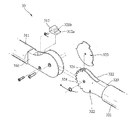
또한 도6에 도시된 바와 같이, 본 고안의 제2실실예는 전술한 제1실시예와 동일한 구성 설명은 생략하고, 제1실시예와 다른 구성에 대해 간략하게 설명하기로 한다.In addition, as shown in Figure 6, the second embodiment of the present invention will be omitted the description of the same configuration as the first embodiment described above, and a brief description of the configuration different from the first embodiment.
본 고안의 제2실시예에 의한 전동 승강 의자(100a)는 구동 모터(151)가 링크(160)에 회전 가능하게 고정된다. 즉, 구동 모터(151) 하부에는 고정공(153)이 형성된 브라켓트(154)가 형성되고, 이 브라켓트(154)에는 일정 길이를 갖는 링크(160)의 일단이 리벳 등의 고정수단에 의해 회전 가능하게 고정되며, 링크(160) 타단은 리벳 등의 고정수단에 의해 프레임(111)에 회전 가능하게 고정된다.In the electric lifting chair 100a according to the second embodiment of the present invention, the driving
이와 같은 본 고안의 제2실시예는 전술한 제1실시예와 동일하므로 그 동작 설명을 생략하기로 한다.Since the second embodiment of the present invention is the same as the first embodiment described above, the description of its operation will be omitted.
도7은 본 고안의 제3실시예를 나타낸 배면도로서, 전술한 제1실시예 또는 제2실시예와 동일한 구성 설명은 생략하고, 전술한 실시예와 다른 구성에 대해 간략하게 설명하기로 한다.FIG. 7 is a rear view showing a third embodiment of the present invention, and the description of the same components as those of the first or second embodiment will be omitted, and will be briefly described. .
본 고안의 제3실시예에 의한 전동 승강 의자는 등받이(132) 배면에 2개의 승강 장치(150)가 설치되어 의자에 사람이 앉은 상태에서 승강되게 한다. 즉, 승강 장치(150)가 하나만 설치된 경우 체중이 무거운 사람이 앉는 상태에서 승강 장치(150)가 구동되어 의자(130)를 안전하게 승강시키게 된다.In the electric lifting chair according to the third embodiment of the present invention, two lifting
아울러 제3실시예는 전술한 제1실시예 또는 제2실시예와 동일하게 작동되므로, 작동 설명은 생략하기로 한다.In addition, since the third embodiment operates in the same manner as the first embodiment or the second embodiment, the description of the operation will be omitted.
도8은 본 고안의 제4실시예를 나타낸 측면도로서, 전술한 제1실시예 또는 제2실시예와 동일한 구성 설명은 생략하고, 전술한 실시예와 다른 구성에 대해 간략하게 설명하기로 한다.FIG. 8 is a side view showing a fourth embodiment of the present invention, and the description of the same components as those of the first embodiment or the second embodiment will be omitted, and will be briefly described.
본 고안의 제4실시예에 의한 전동 승강 의자는 받침대(110)와 의자(130) 사이에 의자(130)를 받치는 지지체(170)가 회전 가능하게 설치된다.In the electric lifting chair according to the fourth embodiment of the present invention, a
지지체(170) 일단은 프레임(111)에 회전 가능하게 고정되는 실린더(171)와 실린더(171)에 출몰되는 로드(172)로 이루어진다. 즉, 실린더(171)는 프레임(111)에 회전 가능하게 고정되고, 로드(172)는 의자(130)의 받침판(131) 저면에 회전 가능하게 고정된다.One end of the
아울러 지지체(170)는 의자(130)가 상승됨에 따라 지지체(170)의 실린더(171)는 회전되고, 로드(172)는 받침판(131)과 함께 상승되면서 도8에서와 같이, 로드(172)가 실린더(171)로부터 길이 연장되어 의자(130)에 가해지는 하중이 지지된다.In addition, as the
아울러 제4실시예는 전술한 제1실시예 또는 제2실시예와 동일하게 작동되므로, 작동 설명은 생략하기로 한다.In addition, since the fourth embodiment operates in the same manner as the first embodiment or the second embodiment, the description of the operation will be omitted.
도1은 종래의 위치제어용 의자를 보인 측면도.Figure 1 is a side view showing a conventional position control chair.
도2a는 종래의 굴절형 좌식 의자를 보인 측단면도.Figure 2a is a side cross-sectional view showing a conventional articulated legless chair.
도2b는 종래의 회전 기구를 보인 분해 사시도.Figure 2b is an exploded perspective view showing a conventional rotating mechanism.
도3은 본 고안의 제1실시예에 따른 전동 승강 의자를 보인 분해 사시도.Figure 3 is an exploded perspective view showing an electric lifting chair according to a first embodiment of the present invention.
도4는 본 고안의 제1실시예에 따른 전동 승강 의자가 상승된 상태를 보인 측면도.Figure 4 is a side view showing a state in which the electric lifting chair in accordance with a first embodiment of the present invention.
도5는 본 고안의 제1실시예에 따른전동 승강 의자가 하강된 상태를 보인 측면도.Figure 5 is a side view showing a state in which the electric lifting chair is lowered according to the first embodiment of the present invention.
도6은 본 고안의 제2실시예를 보인 분해 사시도.Figure 6 is an exploded perspective view showing a second embodiment of the present invention.
도7은 본 고안의 제3실시예를 보인 배면도.Figure 7 is a rear view showing a third embodiment of the present invention.
도8은 본 고안의 제4실시예를 보인 측면도.Figure 8 is a side view showing a fourth embodiment of the present invention.
<도면의 주요 부분에 대한 부호의 설명><Explanation of symbols for main parts of the drawings>
100: 전동 승강 의자 110: 받침대100: electric lifting chair 110: pedestal
111: 프레임 112: 고정 프레임111: frame 112: fixed frame
130: 의자 131: 받침판130: chair 131: support plate
132: 등받이 133: 감지 레버132: backrest 133: sensing lever
134: 고정판 135: 관통공134: fixing plate 135: through hole
136: 고정구 137: 팔걸이136: fixture 137: armrest
150: 승강 장치 151: 구동 모터150: lifting device 151: drive motor
152: 스크류 153: 고정공152: screw 153: fixing hole
154: 브라켓트 155: 고정 브라켓트154: bracket 155: fixing bracket
156: 슬라이딩공 157: 슬라이딩 바156: sliding ball 157: sliding bar
160: 링크160: link
Claims (5)
Priority Applications (1)
| Application Number | Priority Date | Filing Date | Title |
|---|---|---|---|
| KR2020070014275U KR20090002049U (en) | 2007-08-28 | 2007-08-28 | Electric motion Lift Chair |
Applications Claiming Priority (1)
| Application Number | Priority Date | Filing Date | Title |
|---|---|---|---|
| KR2020070014275U KR20090002049U (en) | 2007-08-28 | 2007-08-28 | Electric motion Lift Chair |
Publications (1)
| Publication Number | Publication Date |
|---|---|
| KR20090002049U true KR20090002049U (en) | 2009-03-04 |
Family
ID=41503320
Family Applications (1)
| Application Number | Title | Priority Date | Filing Date |
|---|---|---|---|
| KR2020070014275U KR20090002049U (en) | 2007-08-28 | 2007-08-28 | Electric motion Lift Chair |
Country Status (1)
| Country | Link |
|---|---|
| KR (1) | KR20090002049U (en) |
Cited By (3)
| Publication number | Priority date | Publication date | Assignee | Title |
|---|---|---|---|---|
| WO2011046299A3 (en) * | 2009-10-14 | 2011-08-04 | 한국생산기술연구원 | Lift chair with lifting driving module hinged thereto |
| CN108685374A (en) * | 2017-04-07 | 2018-10-23 | 及桦实业股份有限公司 | Tiltable work chair |
| CN116236361A (en) * | 2023-04-25 | 2023-06-09 | 浙江迈德斯特医疗器械科技有限公司 | Multifunctional lifting chair |
-
2007
- 2007-08-28 KR KR2020070014275U patent/KR20090002049U/en active IP Right Grant
Cited By (4)
| Publication number | Priority date | Publication date | Assignee | Title |
|---|---|---|---|---|
| WO2011046299A3 (en) * | 2009-10-14 | 2011-08-04 | 한국생산기술연구원 | Lift chair with lifting driving module hinged thereto |
| CN108685374A (en) * | 2017-04-07 | 2018-10-23 | 及桦实业股份有限公司 | Tiltable work chair |
| CN108685374B (en) * | 2017-04-07 | 2020-04-28 | 及桦实业股份有限公司 | Tiltable working chair |
| CN116236361A (en) * | 2023-04-25 | 2023-06-09 | 浙江迈德斯特医疗器械科技有限公司 | Multifunctional lifting chair |
Similar Documents
| Publication | Publication Date | Title |
|---|---|---|
| AU2005211844B2 (en) | Adjustable cross-legged support seat | |
| US8801638B2 (en) | Delordosation device | |
| JP5279190B2 (en) | Massage chair | |
| KR101692959B1 (en) | Pose Adjustment Apparatus for Massage Chair | |
| US20110260513A1 (en) | Horizontal oscillating device providing postural adjustment | |
| CA3020908A1 (en) | Reclining armchair with lifting seat and extending footrest | |
| JP2011004925A (en) | Chair | |
| US20160143795A1 (en) | Ergonomic lifting and lowering mechanism for apparatuses for assisting a handicapped person | |
| KR20180038180A (en) | Chair with legs supporter | |
| JP4410845B2 (en) | Portable toilet frame | |
| KR100886181B1 (en) | Chair for handicapped person | |
| KR20090002049U (en) | Electric motion Lift Chair | |
| KR20200046600A (en) | move chair | |
| KR100708303B1 (en) | a chair having the back of a chair with a variable | |
| KR20180038423A (en) | Chair with standing up aid | |
| EP2419069B1 (en) | Seating furniture facilitating rising | |
| KR101683871B1 (en) | Chair for exercising whole-body | |
| KR102050584B1 (en) | Chair | |
| RU87333U1 (en) | ORTHOPEDIC MULTIFUNCTIONAL CHAIR | |
| JP2021109072A (en) | Chair type lumbar traction device | |
| JPH09294791A (en) | Health chair | |
| KR200180804Y1 (en) | Standing typed chair | |
| WO2013187819A1 (en) | Lift chair for assisting user when moving between seated and standing positions | |
| WO2022024138A1 (en) | A height adjustable arm system for furniture's and automobiles seats | |
| JP3056805U (en) | Nursing chair device |
Legal Events
| Date | Code | Title | Description |
|---|---|---|---|
| A201 | Request for examination | ||
| E902 | Notification of reason for refusal | ||
| E701 | Decision to grant or registration of patent right | ||
| NORF | Unpaid initial registration fee |