KR20080098786A - Power supply device and method using harmonic components of radio signals - Google Patents
Power supply device and method using harmonic components of radio signals Download PDFInfo
- Publication number
- KR20080098786A KR20080098786A KR1020070044079A KR20070044079A KR20080098786A KR 20080098786 A KR20080098786 A KR 20080098786A KR 1020070044079 A KR1020070044079 A KR 1020070044079A KR 20070044079 A KR20070044079 A KR 20070044079A KR 20080098786 A KR20080098786 A KR 20080098786A
- Authority
- KR
- South Korea
- Prior art keywords
- information
- signal
- harmonic component
- band
- wireless
- Prior art date
- Legal status (The legal status is an assumption and is not a legal conclusion. Google has not performed a legal analysis and makes no representation as to the accuracy of the status listed.)
- Granted
Links
Images


Classifications
-
- H—ELECTRICITY
- H02—GENERATION; CONVERSION OR DISTRIBUTION OF ELECTRIC POWER
- H02J—ELECTRIC POWER NETWORKS; CIRCUIT ARRANGEMENTS OR SYSTEMS FOR SUPPLYING OR DISTRIBUTING ELECTRIC POWER; SYSTEMS FOR STORING ELECTRIC ENERGY
- H02J50/00—Circuit arrangements or systems for wireless supply or distribution of electric power
- H02J50/20—Circuit arrangements or systems for wireless supply or distribution of electric power using microwaves or radio frequency waves
-
- H—ELECTRICITY
- H02—GENERATION; CONVERSION OR DISTRIBUTION OF ELECTRIC POWER
- H02J—ELECTRIC POWER NETWORKS; CIRCUIT ARRANGEMENTS OR SYSTEMS FOR SUPPLYING OR DISTRIBUTING ELECTRIC POWER; SYSTEMS FOR STORING ELECTRIC ENERGY
- H02J50/00—Circuit arrangements or systems for wireless supply or distribution of electric power
- H02J50/80—Circuit arrangements or systems for wireless supply or distribution of electric power involving the exchange of data, concerning supply or distribution of electric power, between transmitting devices and receiving devices
Landscapes
- Engineering & Computer Science (AREA)
- Computer Networks & Wireless Communication (AREA)
- Power Engineering (AREA)
- Transmitters (AREA)
Abstract
Description
도 1 및 도 2는 종래의 무선전력 공급의 실시예를 나타낸 도면.1 and 2 is a view showing an embodiment of a conventional wireless power supply.
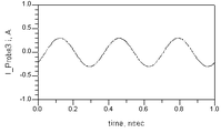
도 3a는 통상의 정보 전달 무선신호를 시간 도메인에서 도시한 파형도3A is a waveform diagram illustrating a typical information delivery radio signal in a time domain.
도 3b 내지 도 3e는 도 3a에 도시된 무선신호의 하모닉 성분을 시간 도메인에서 도시한 파형도.3B to 3E are waveform diagrams showing the harmonic components of the radio signal shown in FIG. 3A in the time domain.
도 3g는 본 발명에 따른 무선신호의 하모닉 성분을 주파수 도메인에서 도시한 도면.3g illustrates the harmonic component of a radio signal in the frequency domain according to the present invention;
도 4는 본 발명에 따른 무선신호를 이용한 전력공급장치를 도시한 블럭도.Figure 4 is a block diagram showing a power supply using a wireless signal according to the present invention.
도 5는 본 발명에 따른 무선신호를 이용한 전력공급장치의 정보복원 회로부를 도시한 블록도.5 is a block diagram showing an information restoration circuit unit of a power supply using a wireless signal according to the present invention.
도 6은 본 발명에 따른 무선신호를 이용한 전력생성방법에 대한 순서도.6 is a flow chart for a power generation method using a wireless signal according to the present invention.
<도면의 주요 부분에 대한 설명>Description of the main parts of the drawing
100: 신호분할기 101: 제1 밴드패스필터 임피던스 매칭회로부 102: 정보복원회로부 103: 제2 밴드패스필터 임피던스 매칭회로부 Reference Signs List 100: signal splitter 101: first band pass filter impedance matching circuit section 102: information restoration circuit section 103: second band pass filter impedance matching circuit section
104: 정류회로부 105: 전압변환부104: rectifier circuit 105: voltage converter
106: 전력제어회로부106: power control circuit
본 발명은 무선신호를 이용한 전력공급장치 및 방법에 관한 것으로, 특히 무선으로 전송받은 신호중 정보를 포함하고 있지 않은 하모닉 신호를 이용하여 전력을 발생시킬 수 있는 무선신호를 이용한 전력공급장치 및 방법에 관한 것이다. The present invention relates to a power supply apparatus and method using a wireless signal, and more particularly to a power supply apparatus and method using a wireless signal that can generate power by using a harmonic signal that does not contain information among the signals transmitted wirelessly. will be.
근래들어 휴대폰, 노트북, 무선로봇, 센서 디바이스, 리모콘, 각종 무선 단말기, 무선 의료기기 등과 같은 휴대용 무선전자기기 및 무선 센서 디바이스가 많이 사용되고 있다. 이러한 기존의 무선전자기기는 고정 위치에 부착되어 외부로부터 항상 동작 전력을 공급받을 수 없으므로, 기기에 포함된 배터리를 통하여 회로에 전력을 공급받는다. 따라서 일정시간이 지나 배터리가 방전되면 배터리를 교체하거나 충전을 해야 한다. 통상적인 충전방식으로 전자기기를 수작업으로 플러그를 콘센트에 꽂아서 전원을 충전하는 방식을 사용하고 있다.In recent years, portable wireless electronic devices and wireless sensor devices such as mobile phones, laptops, wireless robots, sensor devices, remote controllers, various wireless terminals, and wireless medical devices are being used. Since the conventional wireless electronic device is attached to a fixed position and cannot always receive operating power from the outside, power is supplied to the circuit through a battery included in the device. Therefore, if the battery is discharged after a certain time, the battery must be replaced or recharged. As a general charging method, electronic devices are manually plugged into outlets to charge power.
그러나 이 방식은 전자기기 또는 배터리를 전원의 충전이 가능한 곳으로 이동시켜서 전원을 충전해야하는 번거로움이 있고 특히 센서 디바이스와 같이 원거리에 있거나 다수가 분산되어 정확한 위치 추적이 어려운 무선전자기기의 경우 충전이 어렵거나 불가능하다.However, this method is cumbersome to charge the power by moving the electronic device or battery to a place where the power can be charged, especially in the case of wireless electronic devices, such as sensor devices, which are remote or many distributed and difficult to accurately locate. Difficult or impossible
때문에 무선신호를 통한 전력 공급 또는 충전의 필요성이 크게 대두되고 있 다.Therefore, the need for power supply or charging via wireless signals is increasing.
종래에도 무선신호를 통하여 전력을 공급하려는 시도가 있었으며, 최초로 무선으로 작동되는 무인 헬리콥터에 전력을 공급하기 위해 마이크로웨이브를 전송하는 방식이 1959년에 시도되고, 그 후 대체에너지 개발의 일환으로 대기권 밖의 인공위성에서 얻어진 태양전력을 지구로 보내는 무선전력송신(wireless power transmission) 기술이 미국에서 시도되었다. In the past, there have been attempts to supply power through radio signals, and in 1959, a method of transmitting microwaves to power an unmanned helicopter operated wirelessly was attempted in 1959, and then, as part of alternative energy development, out of the atmosphere. Wireless power transmission technology has been attempted in the United States to send solar power from satellites to Earth.
이러한 접근 방식은 무선신호를 전력전송의 용도로만 이용하려는 것이므로 정보전달과 별개인 전력송신만을 위한 별도의 주파수 대역의 신호를 사용하고 있다. 별도의 주파수 대역 사용을 사용하면 안테나를 포함한 무선시스템 자체가 전력 전송을 위한 것이어야 하고, 이는 설계 및 생산을 위한 추가적 비용이 발생한다.This approach is to use the radio signal only for power transmission, and therefore uses a separate frequency band signal for power transmission separate from information transmission. With the use of separate frequency bands, the radio system itself, including the antenna, must be for power transmission, which incurs additional costs for design and production.
도 1은 무선충전방식의 또 다른 방식으로 전자기 유도를 이용한 무선 충전방식을 이용한 패드 형태의 무선충전기기를 도시한 도면이다. 1 is a view showing a pad-type wireless charger using a wireless charging method using electromagnetic induction as another method of the wireless charging method.
도시된 바와 같이, 전력공급 장치내 유도 코일이 전자기파를 발생시키고, 이를 이용하여 충전하고자하는 무선기기에 부착된 코일에 생성된 유도전류로 필요한 전력을 발생시키는 원리이다. 패드 형태의 무선충전기기 위에 충전하고자 하는 무선전자기기를 올려서 전력을 공급하도록 구현이 되는데, 다만 수~수십 센티 이내의 근거리에서만 전력공급이 가능하다는 단점이 있다. As shown, the induction coil in the power supply device generates electromagnetic waves, by using the induced current generated in the coil attached to the wireless device to be charged using the principle to generate the power. It is implemented to supply power by placing a wireless electronic device to be charged on a pad-type wireless charger, but there is a disadvantage in that power can be supplied only within a few to several tens of centimeters.
도 2는 무선 충전방식의 또 다른 예로써, MIT 전자기파 공진을 이용한 충전방식을 도시한 도면이다. 이 방법 역시 수 미터 이내에서만 전력공급이 가능하다. 2 is a diagram illustrating a charging method using MIT electromagnetic resonance as another example of a wireless charging method. This method can only be powered within a few meters.
이와같이 종래의 무선전력 발생장치는 설계 및 추가 생산 비용이 크게 발생 하여 일반적으로 설치가 불가능하거나, 길어야 수 미터 이내의 거리에서만 무선전력발생이 가능하여 휴대용 무선전자 기기 및 센서소자에는 적용이 불가능한 문제점이 있다. As such, the conventional wireless power generator has a large design and additional production cost, and thus cannot be installed in general, or wireless power generation is possible only at a distance of several meters or less, which is not applicable to portable wireless electronic devices and sensor elements. have.
본 발명은 전술한 문제점을 해결하기 위하여 정보수신을 위하여 무선으로 입력받은 신호중 정보를 포함하고 있지않은 하모닉 성분을 이용하여 전력을 발생시킬 수 있는 무선신호를 이용한 전력공급장치 및 방법을 제공함에 그 목적이 있다.The present invention provides a power supply apparatus and method using a wireless signal that can generate power by using a harmonic component that does not contain information among the signals received wirelessly for information reception in order to solve the above problems. There is this.
전술한 목적을 달성하기 위하여 본 발명에 따른 무선신호를 이용한 전력공급장치는, 정보를 포함하는 무선신호를 수신하는 안테나와, 수신된 신호를 정보대역 하모닉 성분와 비정보대역 하모닉 성분로 분리하는 신호 분할기와, 상기 신호분할기로부터 비정보대역 성분을 공급받고 이를 DC 성분의 전류로 변환하는 정류회로부와, 상기 정류회로부에서 출력된 DC 전류를 DC 전압으로 변환하는 전압변환부를 포함하는 것을 특징으로 한다.In order to achieve the above object, a power supply apparatus using a wireless signal according to the present invention includes an antenna for receiving a radio signal including information, and a signal divider for separating the received signal into an information band harmonic component and a non-information band harmonic component. And a rectifier circuit unit for receiving the non-information band component from the signal splitter and converting the non-information band component into a current of the DC component, and a voltage converter for converting the DC current output from the rectifier circuit unit into a DC voltage.
여기서, 상기 정보대역 하모닉 성분은 정보를 포함하고 있는 주파수 대역의 하모닉 성분이며, 상기 비정보대역 하모닉 성분은 정보를 포함하지 않는 주파수 대역의 하모닉 성분이다. Here, the information band harmonic component is a harmonic component of a frequency band including information, and the non-information band harmonic component is a harmonic component of a frequency band including no information.
본 발명의 다른 면에 따라, 무선기기에 수신되는 정보 전송용 무선 신호로부터 전력을 생성하는 방법에 있어서, 상기 정보 전송용 무선 신호를 안테나를 이용하여 수신하는 단계와, 상기 수신 신호에서 정보가 포함되지 않은 주파수 대역의 하모닉 성분을 추출하는 단계와; 상기 추출된 하모닉 성분을 DC전류로 변환하는 단계와,상기 변환된 DC전류를 DC전압으로 변환하는 단계를 포함하는 것을 특징으로 하는 무선신호를 이용한 전력생성방법이 제공된다.According to another aspect of the present invention, a method for generating power from an information transmission radio signal received by a wireless device, the method comprising: receiving the information transmission radio signal using an antenna and including information in the received signal Extracting harmonic components that are not in the frequency band; A method of generating power using a wireless signal is provided, comprising: converting the extracted harmonic component into a DC current, and converting the converted DC current into a DC voltage.
이하, 첨부된 도면을 참조하여 본 발명의 바람직한 실시예를 상세히 설명하기로 한다. 이하의 실시예는 이 기술 분야에서 통상적인 지식을 가진 자에게 본 발명이 충분히 이해되도록 제공되는 것으로서, 여러 가지 형태로 변형될 수 있으며, 본 발명의 범위가 다음에 기술되는 실시예에 한정되는 것은 아니다. Hereinafter, exemplary embodiments of the present invention will be described in detail with reference to the accompanying drawings. The following embodiments are provided to those skilled in the art to fully understand the present invention, and may be modified in various forms, and the scope of the present invention is limited to the embodiments described below. no.
본 발명의 기술적 사상은 정보를 포함하여 무선전송되는 신호의 하모닉 성분 중 정보를 포함하지 않는 하모닉 성분을 이용하여 무선기기의 동작 전력을 발생시키는 것이다.The technical idea of the present invention is to generate operating power of a wireless device using a harmonic component that does not include information among harmonic components of a signal transmitted wirelessly including information.
즉, 본 발명에서는 수신단 또는 수신기의 안테나에서 받은 신호중 정보를 포함하고 있는 하모닉 성분(주파수 대역의 신호)과 정보를 포함하고 있지 않는 하모닉 성분(주파수 대역 이외의 신호)을 분리한 후, 정보를 포함하고 있는 하모닉 성분은 정보 복원을 위해 사용하고, 정보를 포함하고 있지않은 하모닉 성분은 전력 발생을 위한 회로 부분을 통해 휴대용 무선전자기기 또는 센서 디바이스의 전력으로 사용하거나, 정보 전달이 필요하지 않는 타임 슬롯 경우는 무선으로 전달받은 신호에 포함된 모든 하모닉 성분을 대용 무선전자기기 또는 센서 디바이스의 전력으로 사용하는 것을 그 기본 개념으로 한다.That is, according to the present invention, after separating the harmonic component (signal of frequency band) including the information among the signals received from the antenna of the receiver or the receiver and the harmonic component (signal other than frequency band) not including the information, the information is included. Harmonic components are used for information retrieval, and harmonic components that do not contain information are used as power for portable wireless electronics or sensor devices through the circuit part for power generation, or time slots that do not require information transmission. In this case, the basic concept is to use all the harmonic components included in the wirelessly transmitted signal as power of a substitute wireless electronic device or a sensor device.
모든 전기적 신호는 자체적으로 하모닉 성분을 가지고 있거나, 회로상의 경 로 또는 무선 경로를 따라 신호가 전달되면서 왜곡과 간섭에 의해 하모닉 성분이 신호에 추가된다.Every electrical signal has its own harmonic content, or the harmonic content is added to the signal by distortion and interference as the signal travels along a circuit or wireless path.
반복파형을 갖는 주기적 신호 (또는 비주기적 신호)는 그 신호가 가지고 있는 기본주파수의 사인파(또는 코사인파)와 기본 사인파(또는 코사인파)의 정수배(整數倍)의 주파수를 갖는 사인파(또는 코사인파)로 분해된다. 어떤 신호의 하모닉 성분(harmonics or harmonic components)이란 그 신호를 구성하는 기본주파수 이외의 정수배의 주파수를 갖는 사인파(또는 코사인파)들로 정의된다. 기본주파수의 두배의 주파수를 갖는 사인파를 2차 하모닉 성분이라 하고 세배, 네배 등의 주파수를 갖는 사인파를 각각 3차, 4차 하모닉 성분이라 한다.A periodic signal (or aperiodic signal) having a repetitive waveform is a sine wave (or cosine wave) having a frequency that is an integer multiple of the fundamental frequency of the sine wave (or cosine wave) and the fundamental sine wave (or cosine wave) of the signal. Decompose into Harmonics or harmonic components of a signal are defined as sinusoids (or cosine waves) with frequencies that are integer multiples of the fundamental frequency constituting the signal. A sine wave with a frequency twice the fundamental frequency is called a second harmonic component, and a sine wave with frequencies three, four, etc. is called a third and fourth harmonic components, respectively.
도 3a는 시간을 X축으로 신호의 크기를 Y축으로 하여 통상의 정보신호 파형을 도시하고 있고, 도 3b 내지 도 3f에 이 신호를 구성하고 있는 DC 성분 및 각 하모닉 성분이 도시되어 있다.Fig. 3A shows a typical information signal waveform with time as the X axis and signal size as the Y axis, and the DC component and each harmonic component constituting the signal are shown in Figs. 3B to 3F.
도시된 바와 같이, 도 3a의 신호를 분석하면, 크기 1.4의 DC 성분(도 3b 참조), 크기 0.9 및 1 nsec의 주기(1 GHz)를 갖는 사인파(도 3c 참조), 크기 0.2 및 1/2 nsec의 주기(2 GHz)를 갖는 사인파(도 3d 참조), 크기 0.3 및 1/3 nsec의 주기(3 GHz)를 갖는 사인파(도 3e 참조), 그리고 크기 0.1 및 1/4 nsec의 주기(4 GHz)를 갖는 사인파(도 3f 참조)들의 합으로 구성되어 있다.As shown, when analyzing the signal of FIG. 3A, a sine wave (see FIG. 3C) having a DC component of size 1.4 (see FIG. 3B), a period of size 0.9 and 1 nsec (1 GHz), size 0.2 and 1/2 Sine waves with periods of nsec (2 GHz) (see FIG. 3D), sine waves with periods of size 0.3 and 1/3 nsec (3 GHz) (see FIG. 3E), and periods of sizes 0.1 and 1/4 nsec (4 GHz) and the sum of sine waves (see FIG. 3F).
이 신호를 주파수 도메인(주파수를 X축으로 신호의 크기를 Y축)으로 변환하여 도시하면 도 3g와 같은 분포를 나타낸다. 도 3g의 주파수 도메인 상의 파형은 기본 주파수 성분(1GHz)을 포함하여, DC 성분(0 GHz), 2차 하모닉 성분(2 GHz), 3 차 하모닉 성분(3 GHz), 4차 하모닉 성분(4 GHz)을 각각의 신호 크기대로 임펄스 형태의 막대로 해당 주파수 위치에 나타난다. 따라서 기본 주파수 성분을 포함한 6개의 임펄스 형태의 막대가 주파수 도메인의 도시에 나타난다. When this signal is converted into the frequency domain (frequency in the X axis and the magnitude of the signal in the Y axis), the distribution is shown in FIG. 3G. The waveform on the frequency domain of FIG. 3G includes a fundamental frequency component (1 GHz), including a DC component (0 GHz), a second harmonic component (2 GHz), a third harmonic component (3 GHz), and a fourth harmonic component (4 GHz). ) Is represented by the impulse-shaped bar at each frequency. Thus, six impulse-shaped bars containing fundamental frequency components appear in the frequency domain.
위와 같이 모든 정보 전달 신호는 자체 신호 내부에 하모닉 성분을 가지고 있으며, 또한 회로상의 경로 또는 무선 경로를 따라 신호가 전달되면서 왜곡과 간섭에 의해 하모닉 성분이 원래신호에 추가된다. 따라서 실제 정보를 포함하는 신호는 굉장히 많은 하모닉 성분을 갖는 사인파의 합으로 구성되어 있기 때문에 주파수 도메인 상에서 엔벨로프 형태의 파형을 나타낸다.As described above, every information transmission signal has a harmonic component in its own signal, and the harmonic component is added to the original signal by distortion and interference as the signal is transmitted along a path in a circuit or a wireless path. Therefore, since the signal containing the actual information is composed of a sum of sine waves having a large amount of harmonic components, the waveform in the envelope form is displayed in the frequency domain.
통상 무선통신기기는 정보송수신을 위해 정해진 주파수 대역을 사용하는데, 전술한 이유로 말미암아, 정해진 대역 이외의 대역에 포함된 신호는 송수신기에 포함된 대역신호필터 등을 이용하여 제거한 후 사용한다. In general, a wireless communication device uses a predetermined frequency band for transmitting and receiving information. For the above reason, signals included in a band other than the predetermined band are removed after using a band signal filter included in a transceiver.
본 발명에서는 이와 같이 정보가 포함된 주파수 대역의 신호를 복원하기 위한 성분을 제외한 나머지 대역에 존재하는 하모닉 성분을 단순히 제거하지 않고 이를 이용하여 휴대용 무선기기를 충전하거나 무선기기에서 필요한 전력을 발생시킨다. 또한 무선기기가 정보전달을 하고있지 않은 타임 슬롯에는 무선신호에 포함된 모든 하모닉 성분을 이용하여 휴대용 무선기기를 충전하거나 무선기기에서 필요한 전력을 발생시킨다.In the present invention, instead of simply removing the harmonic components present in the remaining bands except for the component for restoring the signal of the frequency band including the information, the portable wireless device is charged or generated by the wireless device. In addition, in a time slot in which the wireless device is not transmitting information, all the harmonic components included in the wireless signal are used to charge the portable wireless device or generate power required by the wireless device.
이하, 청구범위를 포함한 본 명세서의 전반에 걸쳐 설명의 편의상 정보를 포함된 주파수 대역의 하모닉 성분을 정보대역 하모닉 성분이라 칭하고, 정보를 포함하지 않는 하모닉 성분을 비정보대역 하모닉 성분이라 칭한다Hereinafter, the harmonic component of the frequency band including the information for the convenience of description throughout the present specification including the claims is referred to as information band harmonic component, and the harmonic component without information is referred to as non-information band harmonic component.
도 4는 본 발명의 기술적 사상에 따른, 무선신호를 이용한 전력공급장치를 도시한 블럭도이다. 4 is a block diagram illustrating a power supply apparatus using a wireless signal according to the spirit of the present invention.
도 4에 도시된 바와 같이, 안테나로부터 수신된 신호에서 정보대역 하모닉 성분과 비정보대역 하모닉 성분으로 분리하는 신호 분할기(100)와; 정보신호 발생부(200) 및 전력 발생부(300)을 포함한다.As shown in FIG. 4, a
정보신호 발생부(200)는 제1 밴드패스필터 임피던스 매칭회로부(101)와 정보복원 회로부(102)를 포함하고, 전력 발생부(300)은 제2 밴드패스필터 임피던스 매칭회로부(103), 정류회로부(104), 전압변환부(105) 및 전력제어회로부(106)를 포함하여 구성된다. The
신호분할기(100)는 수신기의 안테나(미도시)에 수신된 무선 신호의 하모닉 신호를 전송 정보가 포함된 정보대역 하모닉 성분과 그렇지 않은 비정보대역 하모닉 성분을 분리한다. The
상기와 같이 분리된 정보대역, 비정보대역 하모닉 성분은 정보 신호 발생부(200)와 전력 발생부(300)로 나누어 전달된다. 만약 정보 전송이 필요치 않다면 모든 신호는 전력 발생(300)로 전달되어 사용되게 된다. The separated information band and non-information band harmonic components are transmitted to the
정보 신호 발생부(200)는 제1 밴드패스필터 임피던스 매칭회로부(101)와 정보복원회로부(102)로 구성된다.The
제1 밴드패스필터 임피던스 매칭회로부(101)는 잡음을 제거하기 위한 대역통과 필터와 안테나와 필터 사이의 임피던스 정합을 위한 임피던스 매칭회로로 구성되며, 신호 발생기에서 분리된 신호중 정보대역 하모닉 성분을 수신하여 해당 주파 수 대역 이외의 하모닉 성분이 남아 있지 않도록 필터링한다. The first band pass filter impedance
임피던스 매칭회로는 하나의 출력단과 입력단을 연결할 때, 서로 다른 두 연결단의 임피던스차에 의한 반사를 줄이려는 회로로 안테나 출력 임피던스와 대역통과필터의 입력 임피던스를 정합시킴으로써 신호 감쇄를 최소화한다.Impedance matching circuit is a circuit to reduce reflection caused by the difference of impedance between two different connection terminals when connecting one output terminal and the input terminal to minimize the signal attenuation by matching the antenna output impedance and the input impedance of the band pass filter.
도 5를 참조하여 무선신호를 이용한 전력공급장치의 정보복원 회로부(102)를 보다 구체적으로 설명한다. Referring to Figure 5 will be described in more detail the
정보복원회로부(102)는 제1 밴드패스필터 임피던스 매칭회로부(101) 출력 신호를 입력받아 정보복원을 위한 신호 처리를 하게 된다. 바람직하게, 정보복원회로부(102)는 RF저잡음 증폭기(401), 자동이득조정회로(402), AD 컨버터(403) 및 복조회로(404)로 구성된다. The information
RF 저잡음 증폭기(401)는 감쇄 및 잡음의 영향에 의해 송신되는 동안 신호 레벨이 약해진 상태로 수신된 RF신호를 잡음은 억제시키면서 신호만을 증폭한다. RF 저잡음 증폭기(401)의 출력 신호는 자동이득조정회로(402)의 입력이 된다. The RF
자동이득조정회로(402)는 입력신호의 신호진폭을 검출하여 출력신호의 진폭이 항상 일정하게 유지되도록 자동적으로 조절하는 회로로서 이 회로를 채용할 경우 다른 채널의 전파강도가 센 지역에서도 미약한 자기채널의 전파를 제대로 수신하여 단말기의 착신율을 높여주는 효과를 갖는다.The automatic
AD 컨버터(403)는 수신된 아날로그 신호를 디지털 신호로 변환하는 역할을 한다. The
AD 컨버터(403)를 통해 디지털화된 신호는 복조회로(404)를 거치게 되어 정 보신호로 복원된다. 여기서, 복조방법은 변조방식에 따라 달라지는데 예를 들어 진폭변조일 때는 복조회로(404)는 정류기 기타 비직선회로에 의해서 이루어지고, 주파수변조나 위상변조일 때는 주파수 판별기와 진폭변조의 복조기를 조합해서 복조가 이루어진다.The signal digitized by the
다시, 도 4로 돌아가서 전력 발생부(300)에 대해 구체적으로 설명한다.4, the
전력 발생부(300)는 제2 밴드패스필터 임피던스 매칭회로부(103), 정류회로부(104), 전압변환부(105) 및 전력제어회로부(106)를 포함하여 구성된다.The
제2 밴드패스필터 임피던스 매칭회로부(103)는 제1 밴드패스필터 임피던스 매칭회로부(101)와 유사하게 구성되는데, 신호 분할기(100)에서 분리된 신호 중 정보와 무관한 비정보대역 하모닉 성분을 입력받고 노이즈를 필터링하는 필터와, 안테나와 필터의 임피던스를 정합하여 신호감쇄를 최소화하여 가능한 최대 전력을 얻을 수 있도록 하는 임피던스 매칭 회로를 포함한다. 제2 밴드패스필터 임피던스 매칭회로부(103)에서 출력된 신호는 정류회로부(104)로 입력된다. The second band pass filter impedance
정류회로부(104)는 제2 밴드패스필터 임피던스 매칭회로부(103)를 통과한 비정보대역 하모닉 성분을 DC 성분으로 바꾸어 주는 역할을 한다. The
여기서, 정류회로부(104)는 반파정류회로, 전파정류회로 및 브릿지 정류회로 등으로 다양하게 구성될 수 있다. 반파 정류회로는 교류의 + 또는 - 의 반 사이클만 전류를 흘려서 부하에 직류를 흘리도록 한 다이오드와 저항으로 구성된 회로로서 반파 정류회로의 출력 전압은 전파 정류회로의 1/2배가 된다. Here, the
그리고 전파정류회로는 다이오드 두개를 사용하여 교류의 +, - 사이클 둘 다 에 대해서도 정류를 하고, 부하에 직류 전류를 흘리도록 한 회로를 이용한다. 전파 정류회로에는 중간 탭이 있는 트랜스를 사용하여야 한다. 브릿지 정류회로는 가장 일반적으로 사용하는 정류회로로 다이오드 4개를 브릿지 모양으로 접속하여 사용하는 회로이다. 중간 탭이 있는 트랜스를 사용하지 않으므로 가격이 저렴하다.The full-wave rectifier circuit uses two diodes to rectify both the + and-cycles of alternating current, and uses a circuit that allows direct current to flow through the load. For full-wave rectifier circuits, transformers with intermediate taps are to be used. The bridge rectifier circuit is the most commonly used rectifier circuit and is a circuit in which four diodes are connected in a bridge shape. It is inexpensive because it does not use a transformer with a middle tap.
전압변환부(105)는 정류회로부(104)로부터 DC 전류를 입력받아 전력을 발생시키는 역할을 하며, 바람직하게는 가변저항 및 콘덴서로 구성된다. 가변저항은 원하는 DC 전압을 발생시키기 위해 저항값을 자유롭게 변화시킬 수 있는 소자이다. 콘덴서는 가변저항과 병렬로 연결되고 일단이 접지되는데,정류회로부(104)에서 출력되는 DC성분 중에 정류되지 않고 남아 있는 AC성분을 제거하기 위해 사용된다. 즉, AC신호가 콘덴서를 통과할 때 DC로 전환되지 않은 AC신호를 접지로 흘려보내는 역할을 한다. The
전압변환부(105)를 통과하여 발생된 전력은 수신기의 무선기기 내의 회로를 구동하기 위한 전력제어회로부(106)로 입력된다. 전력제어부(106)는 무선기기에 적합한 전력이 안정적으로 공급되도록 전압값을 각 무선기기에 맞도록 조정하고, 상기 전압변환부(105)로부터의 전압값을 안정화시키는 역할을 한다.The power generated through the
전술한 전력 발생부(300)에서 발생한 전력은 무선 전자기기에 공급되어 무선 전자기기에 내장된 배터리를 충전하거나 또는 무선 전자기기의 구동이 이용된다.The power generated by the above-described
한편, 전술한 바와 같이, 해당 무선기기에 전달되는 정보를 포함하지 않는 무선신호가 수신된 경우, 모든 하모닉 성분을 전력 발생부(300)에 공급하는 것이 바람직한데, 이를 위하여 상기 신호분할기(100)는 상기 안테나에 수신되는 무선 신 호가 정보를 포함하는지 아닌지를 판단하는 신호 판단부(107)를 더 포함하고, 상기 신호 판단부(107)의 판단결과, 현재 수신되는 무선 신호가 정보를 포함하고 있지 아니한 경우, 상기 신호분할기(100)는 상기 정보대역 하모닉 성분 및 비정보대역 하모닉 성분 모두를 전력 발생부(300)에 전달하여 보다 많은 전력이 발생할 수 있도록 한다. 한편, 신호 판단부(107)은 신호분할기(100) 외의 별도의 장치로 구성될 수도 있음은 물론이다.On the other hand, as described above, when a wireless signal is received that does not include information transmitted to the wireless device, it is preferable to supply all the harmonic components to the
신호 판단부(107)는, 예컨대 자신에게 할당된 타임슬롯 구간에는 정보를 포함하는 신호가 수신된다고 판단하고 그 이외의 타임슬롯 구간에는 정보를 포함하지 않는 신호가 수신된다고 판단할 수 있다.The
도 6은 본 발명의 일실시예에 따른 무선 신호를 이용한 전력생성방법의 동작순서를 도시한 흐름도이다. 6 is a flowchart illustrating an operation procedure of a power generation method using a wireless signal according to an embodiment of the present invention.
도 6에 도시된 바와 같이, 송신기로부터 전송된 무선 신호가 대기 또는 특정 매체를 통해 수신기의 안테나에 수신되면(S201), 신호분할기(100)는 수신된 무선신호를 정보를 포함하고 있는 정보대역 하모닉 성분과 정보를 포함하고 있지 않은 비정보대역 하모닉 성분으로 분리한다(S202). As shown in FIG. 6, when a radio signal transmitted from a transmitter is received by an antenna of a receiver through air or a specific medium (S201), the
여기서, 정보를 포함하고 있지 않은 비정보대역 하모닉 성분은 전력발생경로의 입력으로 전달되는데, 정보를 수신하지 않는 타임 슬롯의 경우에는 제1 및 제2 하모닉 성분을 포함한 모든 하모닉 성분은 전력발생경로의 입력으로 전달된다. Here, the non-information band harmonic component that does not contain information is transmitted to the input of the power generation path. In the case of a time slot not receiving information, all harmonic components including the first and second harmonic components are included in the power generation path. Passed as input.
상기 분리된 비정보대역 하모닉 성분은 제2 밴드패스필터 임피던스 매칭부(103)로 입력되어 필터링되어 불필요한 잡음성분을 제거한다(S203). The separated non-information band harmonic component is input to the second band pass filter
여기서, 제2 밴드패스필터 임피던스 매칭회로부(103)는 안테나와 필터의 임피던스를 정합하여 수신된 신호의 전력을 최대화한다. Here, the second band pass filter impedance
상기 임피던스 매칭되어 잡음제거된 비정보대역 하모닉 성분은 정류회로부(104)를 거쳐서 DC전류로 변환된다(S204). The non-information band harmonic component whose noise is matched and noise-removed is converted into a DC current through the rectifier circuit 104 (S204).
상기 정류부를 거친 DC전류는 전압변환부(105)를 통하여 DC전압으로 변환된다(S205). 전압변환부(105)는 정류회로부(104)를 거쳐서 직류로 변환된 신호중 잔류된 AC 성분 제거한다. The DC current passed through the rectifier is converted into a DC voltage through the voltage converter 105 (S205). The
그리고, 전압변환부(105)를 통해서 출력된 DC 전력은 무선기기의 전력제어회로부(106) 또는 밧데리로 공급되어 무선기기회로에 공급된다. The DC power output through the
한편, 신호분할기(100)에서 분리된 신호 중 정보를 포함하고 있는 정보대역 하모닉 성분은 제1 밴드패스필터 임피던스 매칭부(101)를 통과하여 노이즈가 제거되고(S206), 이어 임피던스 매칭된 정보대역 하모닉 성분은 정보복원회로부(102)의 입력으로 전달되어 정보신호로 복원된다(S207).Meanwhile, the information band harmonic component including information among the signals separated by the
이상에서와 같이 상세한 설명과 도면을 통해 본 발명의 실시예를 개시하였다. 용어들은 단지 본 발명을 설명하기 위한 목적에서 사용된 것이지 의미 한정이나 특허청구범위에 기재된 본 발명의 범위를 제한하기 위하여 사용된 것은 아니다. 그러므로 본 기술 분야의 통상의 지식을 가진 자라면 이로부터 다양한 변형 및 균등한 타 실시예가 가능하다는 점을 이해할 것이다. 따라서 본 발명의 진정한 기술적 보호 범위는 첨부된 특허청구범위의 기재에 의해 정해져야 할 것이다.As described above, embodiments of the present invention have been disclosed through the detailed description and the drawings. The terms are used only for the purpose of describing the present invention and are not used to limit the scope of the present invention as defined in the meaning or claims. Therefore, those skilled in the art will understand that various modifications and equivalent other embodiments are possible from this. Therefore, the true technical protection scope of the present invention will be defined by the description of the appended claims.
이상의 설명에서와 같이, 본 발명에 따른 무선신호를 이용한 전력공급장치 및 방법은 각종 휴대용 무선전자기기, 소형로봇 기타 무선 센서 디바이스 등의 무선기기에 무선으로 전달받은 정보 전달 신호로부터 전력을 발생시켜 기기에 내장된 배터리를 충전하거나, 무선기기를 동작시킬 수 있으므로, 내장 배터리가 필요없거나 작은 용량의 배터리를 이용하게 할 수 있어 제품의 소형화에 기여할 수 있다.As described above, the power supply apparatus and method using a wireless signal according to the present invention generates power from the information transmission signal wirelessly transmitted to a wireless device, such as various portable wireless electronic devices, small robots and other wireless sensor devices The built-in battery can be charged or the wireless device can be operated, so that the built-in battery can be used or a small capacity battery can be used, contributing to miniaturization of the product.
특히 기상 정보, 산불 방지 등으로 사용되는 비산되어 배치되는 더스트(dust) 개념의 임의 이식용 유비쿼터스 센서 디바이스의 경우 배터리의 수명이 다한 경우 재충전이 불가능하거나 배터리 또는 기기 자체를 교환해야 하는 단점이 있는데, 본 발명을 이용할 경우 이러한 단점을 해결할 수 있다. 또한 하수구 관리 및 정보 수집을 위한 소형 로봇에 정보 전달과 전력 공급을 동시에 행할 수 있는 효과를 발휘할 수 있다.In particular, any implanted ubiquitous sensor device in the dust concept, which is scattered and used for weather information, forest fire prevention, etc., has a disadvantage in that it cannot be recharged when the battery reaches the end of its life, or the battery or the device itself must be replaced. This disadvantage can be solved by using the present invention. In addition, the small robot for sewer management and information collection can be used to simultaneously transmit information and power.
Claims (12)
Priority Applications (1)
| Application Number | Priority Date | Filing Date | Title |
|---|---|---|---|
| KR1020070044079A KR100898768B1 (en) | 2007-05-07 | 2007-05-07 | Power supply device and method using harmonic components of radio signals |
Applications Claiming Priority (1)
| Application Number | Priority Date | Filing Date | Title |
|---|---|---|---|
| KR1020070044079A KR100898768B1 (en) | 2007-05-07 | 2007-05-07 | Power supply device and method using harmonic components of radio signals |
Publications (2)
| Publication Number | Publication Date |
|---|---|
| KR20080098786A true KR20080098786A (en) | 2008-11-12 |
| KR100898768B1 KR100898768B1 (en) | 2009-05-20 |
Family
ID=40286022
Family Applications (1)
| Application Number | Title | Priority Date | Filing Date |
|---|---|---|---|
| KR1020070044079A Expired - Fee Related KR100898768B1 (en) | 2007-05-07 | 2007-05-07 | Power supply device and method using harmonic components of radio signals |
Country Status (1)
| Country | Link |
|---|---|
| KR (1) | KR100898768B1 (en) |
Cited By (3)
| Publication number | Priority date | Publication date | Assignee | Title |
|---|---|---|---|---|
| WO2012087469A3 (en) * | 2010-12-22 | 2013-08-01 | General Electric Company | Method and system for control power in remote dc power systems |
| US9048695B2 (en) | 2009-12-24 | 2015-06-02 | Samsung Electronics Co., Ltd. | Wireless power transmission device and method |
| KR20200037621A (en) * | 2018-10-01 | 2020-04-09 | 성균관대학교산학협력단 | Apparatus and method for receiving wireless power and information |
Family Cites Families (1)
| Publication number | Priority date | Publication date | Assignee | Title |
|---|---|---|---|---|
| KR100575744B1 (en) * | 2003-10-14 | 2006-05-03 | 엘지전자 주식회사 | Communication and charging device using near field communication unit |
-
2007
- 2007-05-07 KR KR1020070044079A patent/KR100898768B1/en not_active Expired - Fee Related
Cited By (7)
| Publication number | Priority date | Publication date | Assignee | Title |
|---|---|---|---|---|
| US9048695B2 (en) | 2009-12-24 | 2015-06-02 | Samsung Electronics Co., Ltd. | Wireless power transmission device and method |
| WO2012087469A3 (en) * | 2010-12-22 | 2013-08-01 | General Electric Company | Method and system for control power in remote dc power systems |
| CN103380558A (en) * | 2010-12-22 | 2013-10-30 | 通用电气公司 | Method and system for controlling power in a remote DC power system |
| US9450412B2 (en) | 2010-12-22 | 2016-09-20 | General Electric Company | Method and system for control power in remote DC power systems |
| CN103380558B (en) * | 2010-12-22 | 2016-12-21 | 通用电气公司 | Method and system for controlling power in a remote DC power system |
| US10103576B2 (en) | 2010-12-22 | 2018-10-16 | General Electric Company | Method and system for control power in remote DC power systems |
| KR20200037621A (en) * | 2018-10-01 | 2020-04-09 | 성균관대학교산학협력단 | Apparatus and method for receiving wireless power and information |
Also Published As
| Publication number | Publication date |
|---|---|
| KR100898768B1 (en) | 2009-05-20 |
Similar Documents
| Publication | Publication Date | Title |
|---|---|---|
| KR102047963B1 (en) | Wireless charge apparatus and wirelss charge method | |
| US10778034B2 (en) | Circuit and architecture for a demodulator for a wireless power transfer system and method therefor | |
| US10879746B2 (en) | Wireless charging device with multi-tone data receiver and active power supply noise cancellation circuitry | |
| US9995777B2 (en) | Device detection through dynamic impedance change measurement | |
| US9264108B2 (en) | Wireless power carrier-synchronous communication | |
| KR101714335B1 (en) | Adaptive impedance tuning in wireless power transmission | |
| EP2269408B1 (en) | Packaging and details of a wireless power device | |
| KR101110325B1 (en) | Wireless Charging System Using Resonance and Magnetic Field Communication | |
| EP2381556A2 (en) | Power receiving apparatus and wireless power transceiving system | |
| US20120155344A1 (en) | Out-of-band communication on harmonics of the primary carrier in a wireless power system | |
| JP2020025457A (en) | Power receiving device | |
| US10770928B2 (en) | Wireless charging device with multi-tone data receiver | |
| KR100898768B1 (en) | Power supply device and method using harmonic components of radio signals | |
| KR101022760B1 (en) | Wireless electromagnetic wave generation system | |
| US20070105524A1 (en) | Remotely powered wireless microphone | |
| JP4460546B2 (en) | Communication system, transmitter and receiver | |
| CN203069680U (en) | Electromagnetic wave detection device | |
| CN113131629B (en) | Wireless charging device and detection module thereof | |
| WO2023038795A2 (en) | Harmonic current monitoring in a wireless power system | |
| US20250246944A1 (en) | Integrated circuit, wireless power transmission device, and operating method of wireless power transmission device | |
| KR20200113371A (en) | Method and Apparatus for Detecting NFC Device in Wireless Power Transmitter |
Legal Events
| Date | Code | Title | Description |
|---|---|---|---|
| A201 | Request for examination | ||
| PA0109 | Patent application |
St.27 status event code: A-0-1-A10-A12-nap-PA0109 |
|
| PA0201 | Request for examination |
St.27 status event code: A-1-2-D10-D11-exm-PA0201 |
|
| P11-X000 | Amendment of application requested |
St.27 status event code: A-2-2-P10-P11-nap-X000 |
|
| P13-X000 | Application amended |
St.27 status event code: A-2-2-P10-P13-nap-X000 |
|
| D13-X000 | Search requested |
St.27 status event code: A-1-2-D10-D13-srh-X000 |
|
| D14-X000 | Search report completed |
St.27 status event code: A-1-2-D10-D14-srh-X000 |
|
| PG1501 | Laying open of application |
St.27 status event code: A-1-1-Q10-Q12-nap-PG1501 |
|
| E902 | Notification of reason for refusal | ||
| PE0902 | Notice of grounds for rejection |
St.27 status event code: A-1-2-D10-D21-exm-PE0902 |
|
| E13-X000 | Pre-grant limitation requested |
St.27 status event code: A-2-3-E10-E13-lim-X000 |
|
| P11-X000 | Amendment of application requested |
St.27 status event code: A-2-2-P10-P11-nap-X000 |
|
| P13-X000 | Application amended |
St.27 status event code: A-2-2-P10-P13-nap-X000 |
|
| E701 | Decision to grant or registration of patent right | ||
| PE0701 | Decision of registration |
St.27 status event code: A-1-2-D10-D22-exm-PE0701 |
|
| GRNT | Written decision to grant | ||
| PR0701 | Registration of establishment |
St.27 status event code: A-2-4-F10-F11-exm-PR0701 |
|
| PR1002 | Payment of registration fee |
St.27 status event code: A-2-2-U10-U11-oth-PR1002 Fee payment year number: 1 |
|
| PG1601 | Publication of registration |
St.27 status event code: A-4-4-Q10-Q13-nap-PG1601 |
|
| PR1001 | Payment of annual fee |
St.27 status event code: A-4-4-U10-U11-oth-PR1001 Fee payment year number: 4 |
|
| FPAY | Annual fee payment |
Payment date: 20130111 Year of fee payment: 5 |
|
| PR1001 | Payment of annual fee |
St.27 status event code: A-4-4-U10-U11-oth-PR1001 Fee payment year number: 5 |
|
| PN2301 | Change of applicant |
St.27 status event code: A-5-5-R10-R13-asn-PN2301 St.27 status event code: A-5-5-R10-R11-asn-PN2301 |
|
| FPAY | Annual fee payment |
Payment date: 20131231 Year of fee payment: 6 |
|
| PR1001 | Payment of annual fee |
St.27 status event code: A-4-4-U10-U11-oth-PR1001 Fee payment year number: 6 |
|
| FPAY | Annual fee payment |
Payment date: 20150109 Year of fee payment: 7 |
|
| PR1001 | Payment of annual fee |
St.27 status event code: A-4-4-U10-U11-oth-PR1001 Fee payment year number: 7 |
|
| FPAY | Annual fee payment |
Payment date: 20151224 Year of fee payment: 8 |
|
| PR1001 | Payment of annual fee |
St.27 status event code: A-4-4-U10-U11-oth-PR1001 Fee payment year number: 8 |
|
| P22-X000 | Classification modified |
St.27 status event code: A-4-4-P10-P22-nap-X000 |
|
| FPAY | Annual fee payment |
Payment date: 20170512 Year of fee payment: 9 |
|
| PR1001 | Payment of annual fee |
St.27 status event code: A-4-4-U10-U11-oth-PR1001 Fee payment year number: 9 |
|
| FPAY | Annual fee payment |
Payment date: 20180406 Year of fee payment: 10 |
|
| PR1001 | Payment of annual fee |
St.27 status event code: A-4-4-U10-U11-oth-PR1001 Fee payment year number: 10 |
|
| P22-X000 | Classification modified |
St.27 status event code: A-4-4-P10-P22-nap-X000 |
|
| LAPS | Lapse due to unpaid annual fee | ||
| PC1903 | Unpaid annual fee |
St.27 status event code: A-4-4-U10-U13-oth-PC1903 Not in force date: 20190515 Payment event data comment text: Termination Category : DEFAULT_OF_REGISTRATION_FEE |
|
| PC1903 | Unpaid annual fee |
St.27 status event code: N-4-6-H10-H13-oth-PC1903 Ip right cessation event data comment text: Termination Category : DEFAULT_OF_REGISTRATION_FEE Not in force date: 20190515 |
|
| R18-X000 | Changes to party contact information recorded |
St.27 status event code: A-5-5-R10-R18-oth-X000 |
|
| PN2301 | Change of applicant |
St.27 status event code: A-5-5-R10-R13-asn-PN2301 St.27 status event code: A-5-5-R10-R11-asn-PN2301 |
|
| PN2301 | Change of applicant |
St.27 status event code: A-5-5-R10-R13-asn-PN2301 St.27 status event code: A-5-5-R10-R11-asn-PN2301 |