KR20080098593A - Unit for applying opening device to packaging of liquid food - Google Patents
Unit for applying opening device to packaging of liquid food Download PDFInfo
- Publication number
- KR20080098593A KR20080098593A KR1020087018784A KR20087018784A KR20080098593A KR 20080098593 A KR20080098593 A KR 20080098593A KR 1020087018784 A KR1020087018784 A KR 1020087018784A KR 20087018784 A KR20087018784 A KR 20087018784A KR 20080098593 A KR20080098593 A KR 20080098593A
- Authority
- KR
- South Korea
- Prior art keywords
- opening device
- wheel
- unit
- package
- path
- Prior art date
- Legal status (The legal status is an assumption and is not a legal conclusion. Google has not performed a legal analysis and makes no representation as to the accuracy of the status listed.)
- Granted
Links
Images


Classifications
-
- B—PERFORMING OPERATIONS; TRANSPORTING
- B65—CONVEYING; PACKING; STORING; HANDLING THIN OR FILAMENTARY MATERIAL
- B65B—MACHINES, APPARATUS OR DEVICES FOR, OR METHODS OF, PACKAGING ARTICLES OR MATERIALS; UNPACKING
- B65B61/00—Auxiliary devices, not otherwise provided for, for operating on sheets, blanks, webs, binding material, containers or packages
- B65B61/18—Auxiliary devices, not otherwise provided for, for operating on sheets, blanks, webs, binding material, containers or packages for making package-opening or unpacking elements
- B65B61/186—Auxiliary devices, not otherwise provided for, for operating on sheets, blanks, webs, binding material, containers or packages for making package-opening or unpacking elements by applying or incorporating rigid fittings, e.g. discharge spouts
-
- B—PERFORMING OPERATIONS; TRANSPORTING
- B31—MAKING ARTICLES OF PAPER, CARDBOARD OR MATERIAL WORKED IN A MANNER ANALOGOUS TO PAPER; WORKING PAPER, CARDBOARD OR MATERIAL WORKED IN A MANNER ANALOGOUS TO PAPER
- B31B—MAKING CONTAINERS OF PAPER, CARDBOARD OR MATERIAL WORKED IN A MANNER ANALOGOUS TO PAPER
- B31B50/00—Making rigid or semi-rigid containers, e.g. boxes or cartons
- B31B50/74—Auxiliary operations
- B31B50/81—Forming or attaching accessories, e.g. opening devices, closures or tear strings
- B31B50/84—Forming or attaching means for filling or dispensing contents, e.g. valves or spouts
Landscapes
- Engineering & Computer Science (AREA)
- Mechanical Engineering (AREA)
- Specific Conveyance Elements (AREA)
- Auxiliary Devices For And Details Of Packaging Control (AREA)
- Making Paper Articles (AREA)
- Control And Other Processes For Unpacking Of Materials (AREA)
- Supplying Of Containers To The Packaging Station (AREA)
- Intermediate Stations On Conveyors (AREA)
- Filling Of Jars Or Cans And Processes For Cleaning And Sealing Jars (AREA)
Abstract
본 발명은 유동성 식품의 포장(3)에 개구 장치(2,2')를 적용하는 유닛(1,1')에 관한 것으로서, 상기 유닛은 제1 경로(P1,P1')를 따라 연속적으로 개구 장치(2,2')를 제공하는 제1 운반 수단(8,8'); 제2 경로(P2)를 따라 연속적으로 포장(3)을 공급하는 제2 운반 수단(9); 및 제1 경로(P1,P1')로부터 상기 제2 경로(P2)로 개구 장치(2,2')를 전송하는 전송 수단을 포함하며, 그리고 축(A)을 중심으로 회전하는 휠(18) 및 휠(18)에 의해 운반되며 제1 운반 수단(8,8')으로부터 개별적인 개구 장치(2,2')를 수용하는 다수의 그립 부재(19,19')를 포함하는데; 상기 전송 수단(10)은 휠(18)에 이동가능하게 그립 부재(19,19')를 연결시키는 연결 수단(20), 및 휠(18)이 회전함에 따라 힐(18)에 관한 각각의 그립 부재(19,19')의 위치를 변경시키는 캠 유도 수단(21)을 더 포함한다. The present invention relates to a unit (1,1 ') for applying an opening device (2,2') to a package (3) of flowable food, the unit being continuous along a first path (P 1 , P 1 '). First conveying means 8, 8 ′ for providing opening devices 2, 2 ′; Second conveying means (9) for continuously feeding the package (3) along the second path (P 2 ); And transmission means for transmitting the opening device ( 2 , 2 ') from the first path (P 1 , P 1 ') to the second path (P 2 ), and the wheel rotating about the axis (A) 18 and a plurality of grip members 19, 19 ′ carried by wheels 18 and receiving separate opening devices 2, 2 ′ from the first conveying means 8, 8 ′; The transmission means 10 comprises connecting means 20 for movably connecting the grip members 19, 19 ′ to the wheel 18, and respective grips on the heel 18 as the wheel 18 rotates. It further comprises a cam guide means 21 for changing the position of the members 19, 19 '.
Description
본 발명은 유동성 식품 포장에 개구 장치를 적용하는 유닛에 관한 것이다. The present invention relates to a unit for applying an opening device to a flowable food package.
공지된 바와 같이, 과일 주스, UHT(초고온 처리) 우유, 와인, 토마토 소스 등과 같은 여러 유동석 식품은 살균된 포장재로 만들어진 밀봉 포장에 담겨 판매된다. As is known, many calcite foods, such as fruit juice, UHT (ultra high temperature) milk, wine, tomato sauce and the like, are sold in sealed packages made of sterile packaging.
이러한 유형의 포장의 전형적인 예는 Tetra Brik Aseptic(상표 등록)이라 공지된 액체 또는 유동성 식품용 평행육면체형 포장이고, 이는 적층된 스트립 포장재를 접어서 밀봉함으로써 만들어진다. A typical example of this type of packaging is a parallelepiped package for liquid or flowable food known as Tetra Brik Aseptic (registered trademark), which is made by folding and sealing a laminated strip package.
포장재는 강성 및 세기를 위해 베이스 층을 실질적으로 포함하는 다층 구조를 갖는데, 이는 예컨대, 종이 또는 미네랄-충전 폴리프로필렌 물질 섬유재로 된 층; 및 베이스 층의 양측을 커버하는 가열-밀봉 열가소성 물질, 예컨대, 폴리에틸렌 필름으로 된 여러 층을 포함할 수 있다. The packaging has a multilayer structure that substantially includes a base layer for rigidity and strength, including, for example, a layer of paper or mineral-filled polypropylene material fibrous material; And several layers of heat-sealing thermoplastics, such as polyethylene films, covering both sides of the base layer.
UTH 우유와 같은 장기 보존 식품용 무균 포장의 경우에, 포장재는 또한 가스- 및 광-장벽 층, 예컨대, 알루미늄 포일 또는 에틸 비닐 알코올(EVOH) 필름으로 된 층을 포함하는데, 이는 가열-밀봉 열가소성 물질로 된 층 위에 포개지며, 그 후 식품과 최종적으로 접촉하는 포장의 내부 표면을 형성하는 가열-밀봉 열가소성 물질로 된 다른 층으로 커버된다. In the case of sterile packaging for long term preservation foods such as UTH milk, the packaging also includes gas- and light-barrier layers, such as layers of aluminum foil or ethyl vinyl alcohol (EVOH) films, which are heat-sealed thermoplastics. It is superimposed on a layer of heat and then covered with another layer of heat-sealed thermoplastic material which forms the inner surface of the package which finally comes into contact with the food.
공지된 바와 같이, 이러한 종류의 포장은 완전 자동 포장 기계 상에서 제조되는데, 여기서 연속 튜브가 웹-공급 포장재로부터 형성되고; 포장재 웹은 예컨대, 과산화수소 용액과 같은 화학적인 살균제를 도포함으로써 포장 기계 상에서 살균되고, 일단 살균이 완료되면, 살균제는 포장재의 표면상에서 제거되는데, 예컨대, 가열에 의해 증발되며; 이렇게 살균된 포장재 웹은 닫힌, 살균 환경에서 유지되고, 종으로 접혀 밀봉되어 수직 튜브를 형성한다. As is known, this kind of packaging is produced on a fully automatic packaging machine, wherein a continuous tube is formed from the web-fed packaging; The packaging web is sterilized on the packaging machine, for example by applying a chemical bactericide such as hydrogen peroxide solution, and once sterilization is complete, the sterilizer is removed on the surface of the packaging material, e.g., by heating; This sterilized packaging web is maintained in a closed, sterile environment and folded into a bell to form a vertical tube.
튜브는 살균되거나 살균-처리된 식품으로 채워지고, 밀봉되고 그 후에 섹션에 걸쳐 동일하게 이격되어 절단되어 필로우 팩(pillow pack)을 형성하는데, 이는 물리적으로 접혀 완성된, 예컨대 실질적으로 평행육면체형, 포장으로 개별적으로 형성된다. The tube is filled with sterile or sterile-treated food, sealed and then cut equally spaced across sections to form a pillow pack, which is physically folded and finished, such as a substantially parallelepiped, Individually formed into a package.
대안적으로, 포장재는 블랭크로 절단될 수 있는데, 이는 스핀들(spindles)을 형성시 포장재로 형성되고, 포장은 식품으로 충전되어 밀봉된다. 이러한 유형의 포장의 일례는 상표명 Tetra Rex(상표 등록)이라 공지된 소위 "게이블-탑" 포장이다.Alternatively, the packaging material may be cut into blanks, which are formed into the packaging material when forming spindles, and the packaging is filled with food and sealed. An example of this type of packaging is a so-called "gable-top" package known under the trade name Tetra Rex (registered trademark).
일단, 형성되면, 상기 포장은 다시 닫힐 수 있는 개구 장치의 애플리케이션과 같은 부가적인 프로세싱을 경험한다. Once formed, the package undergoes additional processing such as application of an opening device that can be closed again.
최근에, 가장 공통적으로 마케팅되는 개구 장치는 주입구(pour opening)를 한정하며, 포장의 최상부 벽의 접합 가능하거나 제거 가능한 부분 또는 홀을 중심으로 고정되는 프레임; 및 상기 프레임에 힌지되거나 스크류된 캡을 포함하는데, 이는 포장을 열기 위해 제거 가능하다. 대안적으로, 다른 유형의 개구, 예컨대, 슬라이드-개구, 장치가 또한 사용된다고 공지된다. Recently, the most commonly marketed opening device includes a frame defining a pour opening, the frame being fixed about the joinable or removable portion or hole of the top wall of the package; And a cap hinged or screwed to the frame, which is removable to open the package. Alternatively, other types of openings, such as slide-openings, devices are also known to be used.
포장의 접합 가능한 부분은 예컨대, 소위 "선적층" 홀에 의해 한정될 수 있는데, 즉, 홀은 장벽 물질로 된 층으로 베이스 층을 커버하기 전에 포장재의 베이스 층에 형성되므로 이는 완전한 것이고, 기밀 무균 밀봉을 보장하기 위해 홀을 닫는 반면, 또한 쉽게 접합 가능하다. The bondable part of the package can be defined, for example, by so-called "shipping" holes, ie the holes are formed in the base layer of the packaging material before covering the base layer with a layer of barrier material, which is perfect and hermetic While closing the hole to ensure a seal, it is also easily joinable.
무균 포장 기계의 경우에, 상술된 개구 장치가 일단 형성되면, 포장 기계로부터 아래에 위치된 온-라인 애플리케이션 유닛에 의해 포장에 직접 일반적으로 적용된다. In the case of aseptic packaging machines, once the above-mentioned opening device is formed, it is generally applied directly to the packaging by an on-line application unit located below from the packaging machine.
가열 밀봉 또는 접착에 의한 개구 장치의 애플리케이션은 포장 및 개구 장치 둘 다에 여러 예비 동작을 포함한다. 특히, 개구 장치가 가열 밀봉에 의해 적용될 때, 개구 장치 및 포장의 홀 또는 접착 가능한 부분에 대한 포장의 가열-밀봉 외부 층 둘 다는 부분적으로 용해되거나, 사전 가열에 의해 부분적으로 부드러워진다.Application of the opening device by heat sealing or gluing involves several preliminary operations in both the packaging and the opening device. In particular, when the opening device is applied by heat sealing, both the opening device and the heat-sealing outer layer of the package to the hole or adhesive part of the package are partially dissolved or partially softened by preheating.
일단 개별적인 포장이 적용되면, 개구 장치는 접촉 물질에 충분히 오래 포장에 견고히 유지되어야만 하여 접착제를 냉각시켜 허용한다. Once the individual packaging has been applied, the opening device must remain firmly in the package long enough for the contact material to allow the adhesive to cool.
유사하게는, 개구 장치가 접착될 때, 접착을 위해 하나 또는 두 개의 부품이 접착제로 코팅되어야만 하고, 부품은 접착제를 허용하기에 충분히 오래 서로 견고히 접촉되어 유지되어야만 한다. Similarly, when the opening device is glued, one or two parts must be coated with an adhesive for adhesion and the parts must remain in firm contact with each other long enough to allow the adhesive.
애플리케이션 유닛은 두 개의, 예컨대, 각각의 개구 장치가 개별적인 포장에 접착되는 각각 근접한 평행 위치를 가는 별도의 무한 경로를 따라 포장 및 개구 장 치를 연속적으로 공급하는 체인, 운반 장치를 실질적으로 포함하는 것으로 공지된다. The application unit is known to comprise substantially two chains, a conveying device, for example, which continuously feeds the packaging and the opening device along separate endless paths, each of which has an adjacent parallel position where each opening device is glued to the individual packaging. do.
대안적으로, 애플리케이션 유닛은 특허 EP-A-1462370호에서 설명되는 바와 같이 공지되는데, 이는 제1, 바람직하게는 직선, 경로를 따라 포장 연속물을 공급하는 제1 선형 단계 컨베이어; 제1 경로에 대향하는 방향으로, 평행하게 신장하는 제2 직선 경로를 따라 개구 장치 연속물을 공급하는 제2 선형 단계 컨베이어; 및 제1 컨베이어 상의 제동 스테이션들 중 하나에 일치하는 픽업 스테이션으로부터, 개구 장치는 개별적인 포장에 적용되고, 제1 컨베이어 상의 제동 스테이션들 중 하나에 일치하는 애플리케이션 스테이션으로 개구 장치를 공급하는 스텝-동작 회전식 원형 컨베이어(carousel conveyor)를 포함한다. Alternatively, the application unit is known as described in patent EP-A-1462370, which comprises a first linear stage conveyor for supplying a packaging series along a first, preferably straight, path; A second linear stage conveyor for feeding the opening device series along a second straight path extending in parallel in a direction opposite the first path; And from the pick-up station corresponding to one of the braking stations on the first conveyor, the opening device is applied to a separate package and feeds the opening device to an application station that matches one of the braking stations on the first conveyor. A carousel conveyor.
특히, 회전식 원형 컨베이어는 원형 경로를 따라 수직 축으로 다수의 중간 워크 스테이션을 통해 개구 장치를 공급하는데, 개구 장치는 정지되어, 개별적인 포장에 적용되기 전에 여러 예비 동작을 겪는다. In particular, the rotary circular conveyor feeds the opening device through a number of intermediate work stations on a vertical axis along a circular path, which is stopped and undergoes several preliminary operations before being applied to an individual package.
두 가지 경우에, 공지된 애플리케이션 유닛의 여러 가지 용도는 예컨대, 포장 공급 레이트를 유닛에 일치시키는 것이 필수적인 애플리케이션에 개구 장치 공급 레이트로 인해 매우 부족하다. 애플리케이션 유닛의 속도를 의미하는 것은 개구 장치 및 포장 둘 다에서 수행되는 가장 긴 동작에 의해 나타내진다. In both cases, the various uses of known application units are very insufficient due to the opening device supply rate, for example in applications where it is necessary to match the packaging supply rate to the unit. Meaning the speed of the application unit is represented by the longest operation performed in both the opening device and the packaging.
게다가, 두 개의 공지된 유형의 유닛은 매우 부피가 크고, 오퍼레이터에 의해 어렵게 접속 가능한 여러 부품이 있다.In addition, two known types of units are very bulky and there are several parts that are difficult to connect by the operator.
본 발명의 목적은 전형적으로 공지된 유닛에 관한 상기 단점에 직접적인 저가 솔루션을 제공하도록 디자인된, 유동성 식품의 포장에 개구 장치를 적용하는 유닛을 제공하는 것이다.It is an object of the present invention to provide a unit that applies an opening device to a package of flowable food, which is typically designed to provide a low cost solution directly to the above disadvantages with known units.
본 발명에 따르면, According to the invention,
- 제1 경로를 따라 연속적으로 상기 개구 장치에 공급되는 제1 운반 수단;First conveying means fed to said opening device continuously along a first path;
- 제2 경로를 따라 연속적으로 상기 포장을 공급하는 제2 운반 수단; 및Second conveying means for feeding the package continuously along a second path; And
- 상기 제1 경로를 따라 위치된 픽업 스테이션으로부터, 상기 제2 경로를 따라 위치되며 개별적인 상기 포장에 개구 장치를 적용하는 애플리케이션 스테이션으로 상기 개구 장치를 전송하는 전송 수단을 포함하는데, 상기 전송 수단은 축을 중심으로 회전하는 휠, 및 상기 제1 운반 수단으로부터 정시에 하나의 개구 장치를 수용하며 이를 상기 휠의 회전에 의해 상기 제2 경로로 전송하는, 상기 휠에 의해 운반되는 적어도 하나의 그립 부재를 포함하는, 유동성 식품의 포장을 개구 장치에 적용하는 유닛이 제공되는데, Transmission means for transferring the opening device from the pick-up station located along the first path to an application station located along the second path and applying the opening device to the individual package, the transmission means being adapted to move the shaft. A wheel that rotates about its center, and at least one grip member carried by the wheel for receiving one opening device on time from the first transport means and transferring it to the second path by rotation of the wheel; A unit is provided for applying a package of flowable food to an opening device,
이는 상기 전송 수단이 상기 휠에 이동 가능하게 상기 그립 부재를 연결시키는 연결 수단; 및 상기 휠이 회전함에 따라 상기 휠에 관한 상기 그립 부재의 위치가 변경되는 유도 수단을 더 포함하는 것을 특징으로 한다. Connecting means for connecting the grip member such that the transmission means is movable to the wheel; And guide means for changing the position of the grip member relative to the wheel as the wheel rotates.
본 발명의 두 개의 바람직한 비제한적인 실시예는 첨부된 도면을 참조하여 예시의 방법으로 설명될 것이다. Two preferred non-limiting embodiments of the invention will be described by way of example with reference to the accompanying drawings.
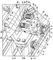
도1은 유동성 식품의 포장에 개구 장치를 적용하는 본 발명에 따른 유닛의, 명확성을 위해 제거된 부품이 있는, 전면도;1 is a front view, with parts removed for clarity, of a unit according to the invention for applying an opening device to a package of flowable food;
도2는 개별적인 포장에 대한 애플리케이션 에어리어에 개별적인 개구 장치를 공급하는 도1 유닛의 개별적인 그립 부재의 제1 확대도;FIG. 2 is a first enlarged view of an individual grip member of the unit of FIG. 1 supplying an individual opening device to an application area for an individual package; FIG.
도3은 도2 그립 부재에 관한 제2 도;3 is a second view of the FIG. 2 grip member;
도4는 도2 및 도3 그립 부재를 동작시키는 액추에이팅 메커니즘에 관한 축소도;4 is an exploded view of an actuating mechanism for operating the grip members of FIGS. 2 and 3;
도5는 도1 유닛의 일부의, 명확성을 위해 제거된 부품이 있는, 측면도;FIG. 5 is a side view of a portion of the FIG. 1 unit, with parts removed for clarity; FIG.
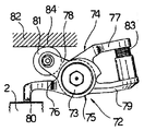
도6은 완전한 접착 동안 개별적인 포장에 개구 장치를 가압하는 도1 유닛의 가압 장치에 관한 도면;Figure 6 is a view of the pressing device of the Figure 1 unit for pressing the opening device to the individual package during complete bonding;
도7은 도6 장치의 가압 부재의 측면도;Figure 7 is a side view of the pressing member of the apparatus of Figure 6;
도8은 본 발명에 따른 유닛의 대안적인 실시예의 도1과 동일한 도면;8 is the same as in FIG. 1 of an alternative embodiment of a unit according to the invention;
도9는 개별적인 포장에 대한 애플리케이션 에어리어에 개별적인 개구 장치를 공급하는 도8 유닛의 그립 부재에 관한 확대도;9 is an enlarged view of the grip member of the FIG. 8 unit supplying the individual opening device to the application area for the individual package;
도10은 도8 유닛의 일부의, 명확성을 위해 제거된 부품이 있는, 측면도; 및FIG. 10 is a side view of a portion of the FIG. 8 unit, with parts removed for clarity; FIG. And
도11은 도9 그립 부재를 동작시키는 액추에이팅 메커니즘의 측면도.Figure 11 is a side view of the actuation mechanism for operating the Figure 9 grip member.
도1에서 숫자 1은 유동성 식품의 밀봉된 포장(3)에 개구 장치(2)를 적용하는 유닛의 전체를 나타낸다. The numeral 1 in FIG. 1 represents the whole of the unit for applying the
포장(3)은 예컨대, 판지와 같은 섬유재로 된 베이스 층 또는 미네랄-충전 폴리프로필렌 물질로 된 베이스 층; 및 베이스 층의 양측을 커버하는 가열-밀봉 열가 소성 물질, 예컨대, 폴리에틸렌 필름으로 된 다층을 포함하는 시트 포장재로부터 상술된 바와 같이 유닛(1)의 위쪽에서 생산된다. UHT 우유와 같은 장기 보존 식품을 위한 무균 포장(3)의 경우에, 포장재는 또한 가스-및 광-장벽 물질, 예컨대, 알루미늄 포일 또는 에틸 비닐 알콜(EVOH) 필름으로 된 층을 포함하며, 이는 가열-밀봉 열가소성 물질로 된 층 위에 포개지며, 그 후 식품과 최종적으로 접촉하는 포장의 내부 표면을 형성하는 가열-밀봉 열가소성 물질로 된 다른 층으로 커버된다. The
도시된 예에서 실질적으로 평행육면체 형태인 각각의 포장(3)은 단부 벽(4)에 개구 또는 접착 가능하거나 제거 가능한 부분(도시되지 않음)을 가지며, 이는 유닛(1)에 의해 포장(3)에 적용되는 개별적인 개구 장치(2)에 의해 밖으로 커버된다. Each
특히, 도1, 도2, 도3, 도5 및 도6은 열가소성 물질로 만들어진 유형의 스크류이고, 각각은 공지된 방법으로 환형의 외부로 스레드된 프레임(threaded frame)(5) 및 개구(6)를 닫도록 프레임(5)에 스크류된 내부로 스레드된 캡(threaded cap)(7)을 포함하는데, 상기 외부로 스레드된 프레임은 개별적인 포장(3) 벽에 고정되며 식품을 따르는 통과 개구(through opening)(6)를 한정한다. 개구 장치(2)는 또한 공지된 방법으로 포장을 밀봉하지 않았을 대 포장(3)의 제거 가능한 부분을 제거하거나 접착 가능한 부분을 접착시키는 수단(도시되지 않음)을 포함할 수 있다.In particular, Figures 1, 2, 3, 5 and 6 are screws of the type made of thermoplastics, each of which has an annular outwardly threaded
도1을 참조하면, 유닛(1)은 공지되고 개략적으로만 도시된, 직선 수평 경 로(P1)를 따라 개구 장치(2)의 연속물을 공급하는 제1 선형 컨베이어(8); 및 또한 공지되고 개략적으로만 도시된, 도시된 예에서 경로(P1)에 대향하는 직선 수평 방향(P2)을 따라 포장(3) 연속물을 공급하는 제2 선형 컨베이어(9); 및 경로(P1)를 따라 위치된 픽업 스테이션(11)으로부터 경로(P2)를 따라 위치된 애플리케이션 스테이션(12)으로 개구 장치(2)를 공급하며 개별적인 포장(3)에 개구 장치(2)를 적용하는 전송 컨베이어 휠(10)을 포함한다. Referring to FIG. 1, the unit 1 comprises a first
컨베이어(8)는 적어도 픽업 스테이션(11)에 근접하게 수평 운반 표면(13)을 한정하는데, 개구 장치(2)는 컨베이어 휠(10)을 마주하는 아래에 캡(7)과 위치된다. The
컨베이어(8)를 따라 이동함에 따라, 개구 장치(2)는 상향 측 상에, 즉, 측향 컨베이어 휠(10)에 대향하여, 접착제로, 바람직하게 경로(P1)를 따라 위치된 건(도시되지 않음)에 의해 코팅된다. As it moves along the
컨베이어(9)는 컨베이어(8) 아래 위치되며, 적어도 애플리케이션 스테이션(12)에 근접하게 수평 운반 표면(14)을 한정하는데, 이는 포장(3)이 개구 장치(2)가 컨베이어 휠(10)을 마주하는, 최상부에서 수평으로 위치된, 최종적으로 적용되는 개별적인 벽(4)에 일치한다. The conveyor 9 is located below the
도시된 예에서, 컨베이어(8)를 따라 개구 장치(2)의 간격(D1)은 컨베이어(9)를 따라 포장(3)의 간격(D2)과 상이하고, 특히 이보다 작으며; "간격"이라는 용어는 두 개의 근접한 개구 장치(2) 또는 두 개의 근접한 포장(3)의 대응하는 지점들 사이의 거리의 의미로 사용된다.In the example shown, the spacing D 1 of the
컨베이어 휠(10)은 경로(P1,P2)에 수직인 수평 축(A)을 중심으로 계속 회전하며, 픽업 스테이션(11)으로부터 애플리케이션 스테이션(2)으로 구부러진 경로(P3)를 따라 개구 장치(2)를 공급한다. The conveyor wheel (10) opening along a path (P 1, P 2) to the application station (2) from and to continue rotating about the horizontal axis (A) perpendicular to, the pick-
컨베이어 휠(10)은 축(A)의 휠(18); 및 축(A)을 중심으로 동일하게 이격되며 휠(18)에 고정되어 휠(18)로부터 방사형으로 돌출되는 다수의 그립 부재(19)를 실질적으로 포함한다. The
유닛(1)은 또한 휠(18)에 이동 가능하게 개별적인 그립 부재(19)를 연결시키는 다수의 연결 어셈블리(20); 및 휠(18)이 회전함에 따라 휠(18)에 대한 각각의 그립 부재(19)의 위치를 변경시키는 캠 유도 부재(21)를 포함하는 것이 유리하다. 그러므로 경로(P3)를 따라 개구 장치(2)의 간격은 개구 장치(2) 상에서 수행될 특정한 동작의 요구 조건에 적응되고(후술됨), 애플리케이션 스테이션(12)에서 포장(3)의 간격(D2)과 동일하게 만들어지는데 필요로 되는 것으로 조정될 수 있다.The unit 1 also includes a plurality of
도1, 도2, 도3, 도5 및 도6을 참조하면, 연결 어셈블리(20)는 축(A)을 중심으로 방사형으로 신장하며 휠(18)의 단부 표면(24)에 고정되어 이로부터 돌출되는 다수의 유도 부재(23); 및 개별적인 유도 부재(23)에 슬라이딩 방법으로 고정되며, 각각 개별적인 그립 부재(19)를 지지하는 다수의 슬라이드 부재(25)를 포함한다.1, 2, 3, 5, and 6, the connecting
특히, 휠(18)은 각각 개별적인 부재(23)에 고정되는 다수의 방사 돌출 부(18b)를 주변으로 돌출시키는 중앙 디스크-형 부분(18a)을 갖는다. In particular, the
각각의 그립 부재(19)는 플레이트(26)에 고정되고, 이는 개별적인 유도 부재(23)에 대향하는 측상에서, 축(A)에 평행한 개별적인 축(B)을 중심으로 플레이트(26)에 수직으로 개별적인 슬라이드 부재(25)에 힌지된다.Each
그러므로 각각의 그립 부재(19)는 축(A)에 대해 소정의 방사 방향으로 휠(18)에 대해 병진될 수 있고, 상기 방사 방향에 부수적인 상기 방사 방향에 수직인 개별적인 축(B)을 중심으로 휠(18)에 대해 진동할 수 있다.Thus each
도1에 도시된 바와 같이, 유도 부재(21)는 각각의 그립 부재(19)의 연결 어셈블리(20)의 슬라이드 부재(25) 및 플레이트(26) 각각에 고정된 유휴 캠 팔로워 롤러(cam follower roller)(29,30)와 공동 동작하며 축(A)을 중심으로 심리스하게 신장하는 두 개의 구부러진 고정 캠(27,28)을 포함한다. As shown in FIG. 1, the
특히, 캠(27,28)은 도1을 참조하여 휠(18) 뒤에 위치된 고정된 수직 벽(33)에 형성된 개별적인 윤곽지어진 글루브(groove)에 의해 한정되거나, 특히, 휠(18) 대향 단부 표면(24)의 단부 표면을 마주하여 위치된다. 캠(28)의 모든 부품은 캠(27)의 방사형 외부에 위치된다.In particular, the
캠(27)은 휠(18)이 회전함에 따라 축(A)에 대한 그립 부재(19)의 방사 위치를 제어하는 반면, 캠(28)은 그립 부재(19)의, 및 개구(2)의 방향 지정을, 이들이 고정된 휠(18)의 반지름에 관하여 제어한다. The
도1에 도시된 바와 같이, 그립 부재(19) 및 개구 장치(2)는 휠(18)이 회전함에 따라 휠(18)에 대한 위치를 변경시키므로 그들의 주변 속도가 바뀐다. 픽업 스 테이션(11) 및 애플리케이션 스테이션(12) 사이의 위치 변경은 개구 장치(2)의 간격을 포장(3) 간격(D2)에 적응시킨다. As shown in Fig. 1, the
도1, 도2, 도3 및 도5를 참조하면, 각각의 그립 부재(19)는 개별적인 슬라이드 부재(25)에 대향하는 측 상에서 플레이트(26)로부터 돌출되는 지지 프레임(34)에 의해 개별적인 플레이트(26)에 고정된다.1, 2, 3 and 5, each
특히, 각각의 프레임(24)은 개별적인 플레이트(26)에 수직인 평면에 실질적으로 L-형의 주요 바디(35)를 포함하며, 플레이트(26)에 평행하게 고정된 제1 플레이트 부분(36), 및 플레이트 부분(36)으로부터 수직으로 돌출되는 제2 플레이트 부분(37)에 의해, 개별적인 슬라이드 부재(25)에 대향하는 측 상에서 한정된다. 각각의 프레임(34)은 또한 개별적인 플레이트 부분(36)에 평행한 방향으로 관련 플레이트 부분(36)을 마주하는 관련 플레이트 부분(37)의 프리 엔드(free end)로부터 신장하는 두 개의 핀(38)을 포함하고; 관련 그립 부재(19)와 완전히 고정되는 패스닝 바디(39)는 핀(38)에 슬라이딩 방법으로 고정되고, 탄성적으로, 개별적인 핀(38)과 동축인 나선형 스프링(40)에 의해, 제1 후퇴 동작 위치(withdrawn operation position)로 적재되는데, 즉, 관련 유도 부재(23)를 따라 관련 슬라이딩 부재(25)에 의해 점유된 특정 방사 부분에 관하여 축(A)으로부터 최소 방사 거리에서 적재된다. In particular, each
특히, 각각의 프레임(34)의 패스닝 바디(39)는 관련 플레이트(26) 및 관련 메인 바디(35)에 평행하게 신장하며, 관련 그립 부재(19)가 관련 플레이트 부 분(37)에 근접하게 대향하는 측 상에서 돌출되는 메인 플레이트 부분(43); 및 플레이트 부분(37)에 근접한 메인 부분(43)의 단부로부터 수직으로 신장하며 개별적인 핀(38)에 의해 슬라이딩 방법으로 맞물려지는 두 개의 통과 홀을 한정하는 부속물(44)을 포함한다. In particular, the
도2 및 도3에 도시된 바와 같이, 각각의 프레임(34)의 핀(38)은 관련 부속물(44)을 통해 신장하며, 부속물(44)로부터 돌출되며 관련 메인 바디(43)와 마주하는 개별적인 부분(46)을 갖는다. 각각의 부분은 부분(46)의 환형 단부 숄더(47) 및 관련 부속물(44) 사이에 내재된 개별적인 스프링(40)과 외부로 감긴다.As shown in FIGS. 2 and 3, the
캠 팔로워 롤러(48)는 관련 메인 부분(43)에 대향하는 측 상에서, 각각의 프레임(34)의 부속물(44)에 고정되어, 이로부터 돌출되고, 스테이션(11,12) 각각에 위치된 두 개의 고정된 캠(50)(도2 및 도5에 도시됨)과 롤링 방법으로 공동 동작한다. The
도2 및 도5를 참조하면, 캠(50)은 캠(28,29)을 지지하는 수직 벽(33)에 휠(18)의 대향하는 측 상에 위치되며, 각각은 축(A)에 관하여 방사형 외부로 돌출되며 각각 대향하여 기울어진 램프 부분(54,55)을 연장시키는 최상부 부분(53)을 포함한다. 횔(18)의 회전 방향을 참고하면, 각각의 캠(5)의 램프 부분(54)은 관련된 최상부 부분(53)을 향하여 위로 기울어지고, 램프 부분(55)은 최상부 부분(53)으로부터 아래쪽으로 기울어진다. 각각의 캠 팔로워 롤러(48)가 각각의 캠(50)을 따라 롤링함에 따라, 관련된 그립 부재(19)는 제1 후퇴 부분으로부터 제2 진행 동작 부분으로 우선 이동되고, 캠(50)의 최상부 부분(53)에 도달되며, 그 후에 그의 원래 위치로 리턴된다.2 and 5, the
제2 진행 동작 위치에서, 각각의 그립 부재(19)는 관련된 유도 부재(23)를 따라 관련된 슬라이드 부재(25)에 의해 점유된 방사 위치에 관하여 축(A)으로부터 최대 방사 거리로 위치된다. 그립 부재(19)에 의한 개구 장치(2)의 픽업 및 해제는 상기 제2 동작 위치에서 각각 수행된다.In the second advancing operating position, each
특히 도2 및 도3을 참조하면, 각각의 그립 부재(19)는 관련 부속물(44)이 신장하는 단부에 대향하는 관련 패스닝 바디(39)의 메인 부분(43) 단부에 고정되어 이로부터 돌출되는 지지 바디(56); 및 축(A)에 관하여 지지 바디(56)의 방사 최외각 측으로부터 돌출되며 관련 개구 장치(2)를 그립하는 세 개의 조(jaw)(57,58,59)를 포함한다. 조들 중 하나(57)는 지지 바디(56)에 고정되는 반면, 두 개의 다른 조(58,59)는 축(A), 및 관련 프레임(34)의 플레이트 부분(37)에 수직인 개별적인 축(C)을 중심으로 병진한다. With particular reference to FIGS. 2 and 3, each
도3에서 도시된 바와 같이, 관련 개구 장치(2)를 그립할 때, 각각의 그립, 부재(19)의 조(57,58,59)는 개구 장치(2)를 중심으로 각을 이뤄 동일하게 이격된다.As shown in Fig. 3, when the associated
특히, 각각의 그립 부재(19)의 조(58,59)는 이들 사이에서 관련 개구 장치(2)를 보유하는 닫힌 위치로 탄성적으로 적재되고, 이들이 개구 장치(2)의 맞물림 및 해제를 허용하도록 구획지어진 개구 위치로 선택적으로 스테이션(11,12)에서 선택적으로 이동 가능하다. In particular, the
각각의 그립 부재(19)의 조(58,59)의 움직임은 도3 및 도4에서 상세히 도시 된 레버-앤드-캠 액추에이팅 메커니즘(lever-and-cam actuating mechanism)(60)에 의해 제어된다. The movement of the
액추에이팅 메커니즘(60)은 관련 그립 부재(19)의 지지 바디(56)에서 홀을 개별적인 통과 홀을 통해 축으로 고정된 회전 방법으로 고정된 두 개의 핀(61a,61b)을 포함하고, 지지 바디(56)로부터 돌출되는 이들의 대향하는 단부는 서로 맞물리는 개별적인 섹터 기어(62,63) 및 개별적인 조(58,59)와 각각 고정된다. 섹터 기어들 중 하나(62)는 개별적인 레버(64)의 단부를 한정하고, 이들의 다른 단부는 스테이션(11,12)에서 각각 위치된 (도3 및 도5에도시된) 두 개의 고정 캠(66)과 롤링 방법으로 동작하는 유휴 캠 팔로워 롤러(65)와 고정된다. The
캠(66)은 캠(28,29)을 지지하는 수직 벽(33)에 휠(18)의 대향하는 측 상에 위치되고, 각각은 휠(18)을 향하여 돌출되고, 개별적인 대향하여 기울어진 램프 부분(68,69)을 연장시키는 최상부 부분(67)을 포함한다. 휠(18)의 회전 방향을 참조하면, 각각의 캠(66)의 램프 부분(68)은 관련 최상부 부분(67)을 향하여 위로 기울어지고, 램프 부분(69)은 최상부 부분(67)으로부터 아래로 기울어진다. The
각각의 캠 팔로워 롤러(65)가 각각의 캠(66)을 따라 롤링함에 따라, 관련 레버(64)는 관련 핀(61a)의 축을 중심으로 우선 회전되어 조(58,59)가 동시에 개구 위치로 이동하며, 최상부 부분(67)에 도달되며, 닫힌 위치로 조(58,59)를 회복시키기 위해 대향하는 방향에서 회전한다.As each
도5, 도6 및 도7을 참조하면, 유닛(1)은 또한 완전한 접착 동안 개별적인 포 장(3) 위에 이들을 견고하게 유지시키기 위해서, 경로(P2)의 부분을 따라 개별적인 스테이션(12)의 개구 장치(2)에 작용하는 가압 장치(70)를 포함한다.5, 6 and 7, the unit 1 also has the
가압 장치(70)는 경로(P2) 및 경로(P1) 사이에 내재된 경로(P2)에 평행한 직선 경로(P4)를 따라 다수의 가압 부재(72)를 공급하며, 경로(P2)를 마주하는 공지된 컨베이어(71)(단지 부분적으로 도시됨)를 포함한다. 가압 부재(72)는 포장(3)의 간격(D2)만큼 동일하게 이격되고, 이들이 포장(3)에 적용되자마자 개별적인 개구 장치(2) 상에 압력을 가한다. The pressurizing
각각의 가압 부재(72)는 컨베이어(71)와 연결시키는 핀(73); 및 핀(73)에 힌지되며 핀(73)을 중심으로 축(X)의 형태로 배열된 개별적인 쌍의 암(76,77 및 78,79)을 포함하는 두 개의 로커 암 레버(74,75)를 실질적으로 포함한다. 특히 경로(P4)를 따라 가압 부재(72)가 이동하는 방향을 참조하면, 각각의 가압 부재(72)의 레버(74,75)의, 개별적인 핀(73)으로부터 위쪽에 위치된 암(76,78)은 관련 개구 장치(2)에 작용하는 가압 핑거(80), 및 관련 고정 캠(82)과 롤링 방법으로 공동 동작하는 캠 팔로워 롤러(81)를 각각 한정하는 반면; 레버(74,75)의, 개별적인 핀(73)으로부터 아래쪽에 위치된 암(77,79)의 프리 엔드는 캠(82)에 접촉하여 관련 캠 팔로워 롤러(81)를 유지시키는 나선형 스프링(83)에 대한 개별적인 좌석 표면(seating surface)을 한정한다. Each pressing
도6에 도시된 바와 같이, 캠(82)은 애플리케이션 스테이션(12)으로부터 신장 하는 메인 부분(84)을 포함하는데, 이는 직선이고, 경로(P2,P4)에 평행하며, 개구 장치(2)와 접촉하여 가압 핑거(80)를 가져오도록, 개별적인 포장(3)에 적용되는, 개구 장치(2)로부터 떨어져 위치된다. 캠(82)은 또한 애플리케이션 스테이션(12)으로부터 위쪽에서 포장(3)을 향하여 아래쪽으로 기울어진 램프 부분(85)을 포함하여, 가압 부재(72)의 가압 핑거(80)를 포장(3)으로부터 완전히 탈착된 위치로부터 포장(3)에 적용된 개구 장치(2)에 접촉하는 위치로 이동시킨다. As shown in FIG. 6, the
상기 설명으로부터 이미 부분적으로는 분명한 유닛(1)의 동작은 접착제로 이미 코팅된 개구 장치는 픽업 스테이션(11)을 통해 이동하는 순간 및 하나의 개구 장치(2)를 참조하여 이제 설명될 것이다.The operation of the unit 1, which is already partly evident from the above description, will now be described with reference to one
개별적인 개구 장치(2)에 대한 그립 부재(19)는 개별적인 캠(27,28)과 상호 작용하는 캠 팔로워 롤러(29,30)에 의해 최상의 픽업 위치에 설정되며, 또한 특정한 주변 속도에 대응하여 축(A)에 대해 희망하는 방사 위치로 캠(27)에 의해 설정된다. 픽업 스테이션(11)에서 그립 부재(19)의 주변 속도는 그립 부재(19) 및 개구 장치(2) 사이의 충격을 최소화하기 위해서 개구 장치(2)의 이동 속도보다 더 큰 것이 바람직하다.The
픽업 스테이션(11)에 도달시, 그립 부재(19)는 관련 캠(50)과 상호 작용하는 그 자신의 캠 팔로워 롤러(48)에 의해 제2 진행 동작 위치로 개구 장치(2)의 경로(P1)를 향해 이동되고, 조(58,59)는 관련 캠(66)과 상호 작용하는 레버(64)의 캠 팔로워 롤러(65)에 의해 열린 위치로 회전된다.Upon reaching the pick-up
그 후에, 그립 부재(19)의 조(58,59)는 관련 개구 장치(2)에 대해 닫히고 그립 부재는 경로(P1)로부터 제1 후퇴 동작 위치로 다시 후퇴된다. Thereafter, the tank (58,59) of the
경로(P3)를 따라 그립 부재(19)의 위치 및 이동 속도는 캠(27,28)과 상호 작용하는 캠 팔로워 롤러(28,29)에 의해 결정되고, 경로(P3)를 따라 개구 장치(2)의 공간은 포장(3)의 공간과 동일하게 만들어진다.The position and speed of movement of the
애플리케이션 스테이션(12)에 근접하게, 그립 부재(19)의 캠 팔로워 롤러(48)는 관련 캠(50)과 상호 작용하여 일단, 개별적인 포장(3) 상에 놓여지면, 개구 장치(2)를 해제하도록 열린 위치로 조(58,59)를 회전시킨다. 관련 가압 부재(72)는 가압 핑거(80)가 접착 동안 개별적인 포장(3) 상에 이를 유지시키도록 개구 장치(2)와 접촉하여 취해지는 열린 위치로 캠(82)과 상호 작용하는 그의 캠 팔로워 롤러(81)에 의해 이동된다.Close to the
후술되는 몇몇 직접적인 대안에 의해, 유닛(1)은 여러 유형의 개구 장치(2')와 동작하도록 디자인된 유닛(1')(도8-도11)으로 변환될 수 있고, 유닛(1')에 상이하게 공급된다. By some direct alternatives described below, the unit 1 can be converted into a unit 1 '(Figs. 8-11) designed to operate with various types of opening arrangements 2', and the unit 1 '. Supplied differently.
도8 및 도9에 도시된 바와 같이, 개구 장치(2')는 편평하고, 실질적으로 직사각형이고, 열가소성 물질로 만들어지며 힌지된다. 각각의 개구 장치(2')는 공지된 방법으로 개별적인 포장(3) 벽(4)에 고정되며 식품을 따르는 통과 개구(도시되지 않음)를 한정하는 주변 프레임(5')(부분적으로만 도시됨); 및 상기 개구를 닫도록 프레임(5')에 힌지된 캡(7')을 포함한다.As shown in Figs. 8 and 9, the opening device 2 'is flat, substantially rectangular, made of thermoplastic and hinged. Each opening device 2 'is fixed to an
개구 장치(2')는 도시된 예에서 단계적으로 동작되는 회전 컨베이어(8')에 의해 환형 경로(P1')를 따라 유닛(1')에 공급되고; 포장(3)의 간격(D2)과 상이한 간격(D1')으로 이격되며; 포장(3)에 접착되도록 개구 장치(2)의 경우에 비해 상대적으로 소량의 접착제를 필요로 하고, 이로 인해 직접적인 코팅 롤러(90)를 사용하여 접착제로 쉽게 코팅될 수 있다.The opening device 2 'is supplied to the unit 1' along the annular path P 1 'by a rotary conveyor 8' stepped in the example shown; Spaced at intervals D 1 ′ different from the interval D 2 of the
캠(27,28)에 의해 제어 가능한 휠(18) 상에서 개구 장치(2')의 주변 속도에 의해서, 개구 장치(2')가 코팅 롤러(90)를 통해 슬라이딩에 의해 접착제로 코팅되도록 하기 위해 적절한 일정 속도로 이동하는 경로(P3)의 일부가 유리하게 형성될 수 있고, 이로 인해 상기 경로는 애플리케이션 스테이션(12)의 바로 이쪽에 휠(18)과 나란히 위치된다. By means of the peripheral speed of the opening device 2 'on the
그러므로 유닛(1)은 경로(P3)를 따라 코팅 롤러(90)를 설정하고, 그립 부재(19)를 개구 장치(2')와 상호 작용하도록 디자인된 그립 부재(19')로 교체하며, 액추에이팅 메커니즘(60)을 적절한 액추에이팅 메커니즘(60')으로 교체함으로써 유닛(1')으로 실질적으로 변환된다. The unit 1 therefore sets the
도8 내지 도11에 도시된 바와 같이, 각각의 그립 부재(19')는 실질적으로 관련 개구 장치(2')의 대향하는 측을 그립하는 두 개의 이동 가능한 조(91,92)를 포함함으로써 관련 그립 부재(19)와 상이하다.As shown in FIGS. 8-11, each
특히, 그립 부재(19')는 실질적으로 평행육면체형 지지 바디(93)를 포함하는데, 이는 지지 바디(56)와 같이, 관련 부속물(44)이 돌출되는 곳에 대향하는 측 상 에서 관련 패스닝 바디(39)의 메인 바디(43)에 고정되고, 이로부터 돌출된다. 조(91,92)는 신장된 바디에 의해 한정되는데, 이는 지지 바디(93)의 대향하는 측을 따라 신장하며, 관련 부속물(44)에 근접하고 축(A)에 수직이며 관련 프레임(34)의 플레이트 부분(37)에 평행한 개별적인 축(D)을 중심으로 지지 바디(93)에 힌지되는 제1 단부 부분(94), 및 실질적으로 관련 개구 장치(2')를 그립하여 유지하도록 마주하는 그의 오목부를 갖는 구부러진 팁의 형태로 축(A)에 관하여 더 방사형 외부에 위치된 대향하는 제2 단부 부분(95)을 포함한다.In particular, the
특히 도11에서 보여지는 바와 같이, 조(91,92)는 축(A)에 평행한 방향으로 지지 바디(93)를 통해 신장하는 원통 나선형 스프링(96)에 의해 닫힌 위치를 한정하도록 서로를 향해 탄성적으로 적재된다. 조(91,92)의 단부 부분(94)은 서로 맞물리는 개별적인 섹터 기어를 한정하고, 이들 중 하나(조(91)에 의해 한정되는 것)는 관련 조(91)에 대향하는 방향으로 관련 축(D)으로부터 신장하는 레버 암(97)과 통합적으로 연결되고, 캠 팔로워 롤러(98)에 고정되는데, 이는 캠(66)과 동일한 두 개의 고정 캠(66')과 롤링 방법으로 공동 동작하여 개별적인 스테이션(11,12)에서 관련 개구 장치(2')의 맞물림 및 해제를 가능하게 하는 열린 위치로 개별적인 축(D)을 중심으로 조(91,92)의 부분적인 회전 움직임을 생성한다. As can be seen in particular in FIG. 11, the
유닛(1')은 유닛(1)과 완전히 동일한 방법으로 동작하는데, 단지 개구 장치(2')가 애플리케이션 스테이션(12) 위쪽의 코팅 롤러(90) 상에서 슬라이딩하고, 상기 코팅 롤러(90)에 의해 접착제로 코팅된다는 것이 상이하다. The unit 1 ′ operates in exactly the same way as the unit 1, with only the
본 발명에 따른 유닛(1,1')의 이점은 상기 설명으로부터 명백해질 것이다. The advantages of the units 1, 1 'according to the invention will become apparent from the above description.
특히, 유닛(1,1')은 매우 다용도이고, 단지 부가적인 대안으로, 여러 유형의 개구 장치(2,2')와 상이하게 동작할 수 있다. 사실, 휠(18)이 회전함에 따라 그립 부재(19,19')의 속도 조절 가능성이 제공된다면, 개구 장치(2) 및 포장(3)이 휠 컨베이어(10)에 공급되는 간격(D1,D2)은 종속적이지 않고, 임의의 필수적인 동작은 개구 장치(2,2')가 컨베이어 휠(10) 상에서 운반됨에 따라 수행될 수 있다.In particular, the units 1, 1 ′ are very versatile and can operate differently from various types of opening
컨베이어 휠(10)의 연속 동작과 함께 개구 장치(2,2') 및 포장(3)이 컨베이어 휠(10)에 공급되는 간격(D1,D2)의 비의존성은 성취될 높은 출력 속도를 가능하게 한다.The independence of the gaps D 1 , D 2 , in which the
게다가, 캠(27,28)에 의해 그립 부재(19,19')의 속도 및 궤적을 제어하는 것은 픽업 스테이션(11)에서 관련 그립 부재(19,19') 및 개구 장치(2,2') 사이의 충격을 최소화시키고; 이러한 목적을 위해서, 스테이션(11)에서 그립 부재(19,19')의 주변 속도는 개구 장치(2,2')가 스테이션(11)에 공급되는 속도보다 큰 것이 바람직하다.In addition, controlling the speed and trajectory of the
마지막으로, 수직으로 휠(18)을 위치시키는 것, 즉, 수평으로 위치된 축(A)과 함께 전체로서 유닛(1,1')에 의해 점유되는 공간을 최소화시키고, 오퍼레이터가 유닛(1,1')의 모든 구성 요소 부품에 쉽게 액세스하도록 한다.Finally, positioning the
그러나 첨부된 청구항에서 한정된 보호 범위를 벗어나지 않고 본원에서 설명되고 도해되는 바와 같은 유닛(1,1')에서 변화가 행해질 수 있다는 것이 명백하다.It is evident, however, that changes may be made in units 1, 1 ′ as described and illustrated herein without departing from the scope of protection defined in the appended claims.
특히, 개구 장치(2,2')는 개별적인 포장(3)에 가열 밀봉될 수 있고, 접착 코 팅 동작은 예컨대, 캠(27,28)의 유도 동작 및 휠(18)의 회전에 의해 결합적으로 생성된 경로(P3)를 따라 또는 휠(18)의 위쪽으로 수행되는 가열 동작에 의해 교체될 것이다.In particular, the
Claims (16)
Applications Claiming Priority (3)
| Application Number | Priority Date | Filing Date | Title |
|---|---|---|---|
| EP06101059A EP1813418B1 (en) | 2006-01-31 | 2006-01-31 | Unit for applying opening devices to packages of pourable food products |
| EP06101059.1 | 2006-01-31 | ||
| PCT/EP2006/070283 WO2007087942A1 (en) | 2006-01-31 | 2006-12-29 | Unit for applying opening devices to packages of pourable food products |
Publications (2)
| Publication Number | Publication Date |
|---|---|
| KR20080098593A true KR20080098593A (en) | 2008-11-11 |
| KR101389242B1 KR101389242B1 (en) | 2014-04-24 |
Family
ID=36636999
Family Applications (1)
| Application Number | Title | Priority Date | Filing Date |
|---|---|---|---|
| KR1020087018784A Expired - Fee Related KR101389242B1 (en) | 2006-01-31 | 2006-12-29 | Unit for applying opening devices to packages of pourable food products |
Country Status (15)
| Country | Link |
|---|---|
| US (1) | US7762043B2 (en) |
| EP (1) | EP1813418B1 (en) |
| JP (1) | JP5185138B2 (en) |
| KR (1) | KR101389242B1 (en) |
| CN (1) | CN101336159B (en) |
| AT (1) | ATE444843T1 (en) |
| BR (1) | BRPI0620814A2 (en) |
| DE (1) | DE602006009612D1 (en) |
| ES (1) | ES2332603T3 (en) |
| MY (1) | MY143767A (en) |
| PL (1) | PL1813418T3 (en) |
| PT (1) | PT1813418E (en) |
| RU (1) | RU2423301C2 (en) |
| UA (1) | UA93698C2 (en) |
| WO (1) | WO2007087942A1 (en) |
Cited By (2)
| Publication number | Priority date | Publication date | Assignee | Title |
|---|---|---|---|---|
| KR101347057B1 (en) * | 2012-05-08 | 2014-01-03 | 오갑석 | spray fabrication device |
| KR102487900B1 (en) * | 2021-12-09 | 2023-01-12 | 이지케이 주식회사 | Apparatus for supplying of buffering net of drug container |
Families Citing this family (16)
| Publication number | Priority date | Publication date | Assignee | Title |
|---|---|---|---|---|
| ATE409645T1 (en) * | 2006-01-31 | 2008-10-15 | Tetra Laval Holdings & Finance | MODULAR UNIT FOR APPLYING OPENING DEVICES TO FOOD PACKAGINGS |
| ITTO20080915A1 (en) * | 2008-12-09 | 2010-06-10 | Tetra Laval Holdings & Finance | UNIT FOR THE APPLICATION OF OPENING DEVICES ON PACKAGES OF VERSABLE FOOD PRODUCTS IN A PACKAGE OF PACKAGING MATERIAL |
| PL2804813T3 (en) * | 2012-01-20 | 2017-05-31 | Å&R Carton Lund Ab | Apparatus and method for application of lids to containers |
| EP2746175A1 (en) * | 2012-12-21 | 2014-06-25 | Tetra Laval Holdings & Finance S.A. | Unit for the application of opening devices on sealed packages of food products |
| EP2927132B1 (en) * | 2014-04-04 | 2016-09-14 | Tetra Laval Holdings & Finance S.A. | Unit for the application of lids of opening devices |
| RS57822B1 (en) * | 2014-10-31 | 2018-12-31 | Cps Company S R L | Packaging machine with a horizontal-axis carousel, particularly for packaging rolls of paper or packs of paper serviettes or other solid products of variable size |
| US10106335B2 (en) * | 2014-11-18 | 2018-10-23 | James Laverdiere | Rotary picker |
| US10773901B2 (en) * | 2014-11-18 | 2020-09-15 | James Laverdiere | Rotary picker with arms |
| CN105600030A (en) * | 2015-11-16 | 2016-05-25 | 青岛海科佳电子设备制造有限公司 | Double-side-opening type longitudinal sealing device |
| JP6517672B2 (en) * | 2015-11-30 | 2019-05-22 | 株式会社 日立産業制御ソリューションズ | Pitch conversion device and inspection device provided with the same |
| IT201700041639A1 (en) * | 2017-04-13 | 2018-10-13 | M C Automations S R L | TRANSFER DEVICE FOR CUTTING MACHINES OF SWEET PRODUCTS |
| DE102017109124A1 (en) | 2017-04-27 | 2018-10-31 | Sig Technology Ag | Application device, application device and method for applying additional elements to packages |
| WO2019215048A1 (en) * | 2018-05-11 | 2019-11-14 | Tetra Laval Holdings & Finance S.A. | Outfeed device for a packaging assembly and packaging assembly comprising an outfeed device |
| CN110901177B (en) * | 2019-12-06 | 2025-07-04 | 池州市谦跃信息技术有限公司 | Wine box cover forming machine |
| JP7569034B2 (en) * | 2020-05-15 | 2024-10-17 | 四国化工機株式会社 | Plugging device and plugging method |
| IT202000015853A1 (en) * | 2020-07-01 | 2022-01-01 | Fameccanica Data Spa | APPARATUS AND PROCEDURE FOR TRANSFER OF ITEMS |
Family Cites Families (15)
| Publication number | Priority date | Publication date | Assignee | Title |
|---|---|---|---|---|
| US3216874A (en) * | 1963-01-07 | 1965-11-09 | Brown Machine Co Of Michigan | Container making methods and apparatus |
| US3499068A (en) * | 1966-04-20 | 1970-03-03 | Brown Machine Co Of Michigan | Methods and apparatus for making containers |
| JPS5225783B1 (en) * | 1970-11-26 | 1977-07-09 | ||
| US3673663A (en) * | 1970-12-11 | 1972-07-04 | Seal Spout Europ Spa | Machine for applying pouring spouts to containers |
| JPS55116510A (en) * | 1979-02-16 | 1980-09-08 | Ckd Corp | Apparatus for automatically mounting lid |
| US4345963A (en) * | 1981-06-01 | 1982-08-24 | Abbott Laboratories | Assembly machine for I.V. components |
| US4548668A (en) * | 1983-01-10 | 1985-10-22 | Continental Can Company, Inc. | Combination machine for assembling container components |
| US4523377A (en) * | 1983-11-22 | 1985-06-18 | Gerber Products Company | Baby bottle cap assembler |
| US5435803A (en) * | 1993-07-01 | 1995-07-25 | Elopak Systems A.G. | Container fitment applicator |
| IT1264178B1 (en) * | 1993-07-28 | 1996-09-23 | Azionaria Costruzioni Acma Spa | CAPPING UNIT FOR AUTOMATIC ASSEMBLY OF PUMP BOTTLES. |
| JP2000000900A (en) * | 1998-06-15 | 2000-01-07 | Shikoku Kakoki Co Ltd | Apparatus for sealing container pouring cylinder |
| DE29908075U1 (en) * | 1999-05-06 | 2000-09-14 | GEA Finnah GmbH, 48683 Ahaus | Device for closing plastic bottles |
| JP2001206305A (en) * | 2000-01-25 | 2001-07-31 | Nippon Jido Seiki Kk | High-speed capper |
| US6463715B1 (en) * | 2001-10-12 | 2002-10-15 | Tetra Laval Holdings & Finance, Sa | Rotary closure applicator |
| EP1462370B2 (en) * | 2003-03-28 | 2011-09-07 | Tetra Laval Holdings & Finance SA | Unit for applying opening devices to packages of pourable food products |
-
2006
- 2006-01-31 AT AT06101059T patent/ATE444843T1/en active
- 2006-01-31 PT PT06101059T patent/PT1813418E/en unknown
- 2006-01-31 PL PL06101059T patent/PL1813418T3/en unknown
- 2006-01-31 ES ES06101059T patent/ES2332603T3/en not_active Expired - Lifetime
- 2006-01-31 EP EP06101059A patent/EP1813418B1/en not_active Expired - Lifetime
- 2006-01-31 DE DE602006009612T patent/DE602006009612D1/en not_active Expired - Lifetime
- 2006-12-29 MY MYPI20082832A patent/MY143767A/en unknown
- 2006-12-29 KR KR1020087018784A patent/KR101389242B1/en not_active Expired - Fee Related
- 2006-12-29 JP JP2008551685A patent/JP5185138B2/en not_active Expired - Fee Related
- 2006-12-29 RU RU2008135372/12A patent/RU2423301C2/en not_active IP Right Cessation
- 2006-12-29 WO PCT/EP2006/070283 patent/WO2007087942A1/en not_active Ceased
- 2006-12-29 UA UAA200809943A patent/UA93698C2/en unknown
- 2006-12-29 BR BRPI0620814-2A patent/BRPI0620814A2/en not_active IP Right Cessation
- 2006-12-29 US US12/162,920 patent/US7762043B2/en active Active
- 2006-12-29 CN CN2006800521638A patent/CN101336159B/en active Active
Cited By (2)
| Publication number | Priority date | Publication date | Assignee | Title |
|---|---|---|---|---|
| KR101347057B1 (en) * | 2012-05-08 | 2014-01-03 | 오갑석 | spray fabrication device |
| KR102487900B1 (en) * | 2021-12-09 | 2023-01-12 | 이지케이 주식회사 | Apparatus for supplying of buffering net of drug container |
Also Published As
| Publication number | Publication date |
|---|---|
| BRPI0620814A2 (en) | 2011-11-22 |
| EP1813418A1 (en) | 2007-08-01 |
| ES2332603T3 (en) | 2010-02-09 |
| WO2007087942A8 (en) | 2007-12-21 |
| RU2423301C2 (en) | 2011-07-10 |
| KR101389242B1 (en) | 2014-04-24 |
| US20090025337A1 (en) | 2009-01-29 |
| DE602006009612D1 (en) | 2009-11-19 |
| PT1813418E (en) | 2009-11-20 |
| RU2008135372A (en) | 2010-03-10 |
| MY143767A (en) | 2011-07-15 |
| JP5185138B2 (en) | 2013-04-17 |
| US7762043B2 (en) | 2010-07-27 |
| JP2009525200A (en) | 2009-07-09 |
| WO2007087942A1 (en) | 2007-08-09 |
| CN101336159B (en) | 2011-10-05 |
| UA93698C2 (en) | 2011-03-10 |
| EP1813418B1 (en) | 2009-10-07 |
| CN101336159A (en) | 2008-12-31 |
| HK1128009A1 (en) | 2009-10-16 |
| ATE444843T1 (en) | 2009-10-15 |
| PL1813418T3 (en) | 2010-03-31 |
Similar Documents
| Publication | Publication Date | Title |
|---|---|---|
| US8499529B2 (en) | Modular unit for applying opening devices to packages of pourable food products | |
| KR101389242B1 (en) | Unit for applying opening devices to packages of pourable food products | |
| US9187199B2 (en) | Unit for the application of opening devices on packages of food products pourable into a tube of packaging material | |
| US8336703B2 (en) | Separating unit for separating opening devices to be applied singly to respective packages of pourable food products | |
| EP1462370B2 (en) | Unit for applying opening devices to packages of pourable food products | |
| EP1215124A1 (en) | Unit for applying opening devices to packages of pourable food products | |
| JP3128338U (en) | A unit that applies an opening device to a package of injectable food | |
| EP1471009A1 (en) | Gripper for opening devices to be applied to packages of pourable food products | |
| HK1128009B (en) | Unit for applying opening devices to packages of pourable food products | |
| HK1127916B (en) | Modular unit for applying opening devices to packages of pourable food products | |
| MX2008009397A (en) | Modular unit for applying opening devices to packages of pourable food products | |
| MX2008009722A (en) | Unit for applying opening devices to packages of pourable food products |
Legal Events
| Date | Code | Title | Description |
|---|---|---|---|
| PA0105 | International application |
St.27 status event code: A-0-1-A10-A15-nap-PA0105 |
|
| PG1501 | Laying open of application |
St.27 status event code: A-1-1-Q10-Q12-nap-PG1501 |
|
| A201 | Request for examination | ||
| P11-X000 | Amendment of application requested |
St.27 status event code: A-2-2-P10-P11-nap-X000 |
|
| P13-X000 | Application amended |
St.27 status event code: A-2-2-P10-P13-nap-X000 |
|
| PA0201 | Request for examination |
St.27 status event code: A-1-2-D10-D11-exm-PA0201 |
|
| E902 | Notification of reason for refusal | ||
| PE0902 | Notice of grounds for rejection |
St.27 status event code: A-1-2-D10-D21-exm-PE0902 |
|
| T11-X000 | Administrative time limit extension requested |
St.27 status event code: U-3-3-T10-T11-oth-X000 |
|
| T11-X000 | Administrative time limit extension requested |
St.27 status event code: U-3-3-T10-T11-oth-X000 |
|
| E13-X000 | Pre-grant limitation requested |
St.27 status event code: A-2-3-E10-E13-lim-X000 |
|
| P11-X000 | Amendment of application requested |
St.27 status event code: A-2-2-P10-P11-nap-X000 |
|
| P13-X000 | Application amended |
St.27 status event code: A-2-2-P10-P13-nap-X000 |
|
| E701 | Decision to grant or registration of patent right | ||
| PE0701 | Decision of registration |
St.27 status event code: A-1-2-D10-D22-exm-PE0701 |
|
| GRNT | Written decision to grant | ||
| PR0701 | Registration of establishment |
St.27 status event code: A-2-4-F10-F11-exm-PR0701 |
|
| PR1002 | Payment of registration fee |
St.27 status event code: A-2-2-U10-U12-oth-PR1002 Fee payment year number: 1 |
|
| PG1601 | Publication of registration |
St.27 status event code: A-4-4-Q10-Q13-nap-PG1601 |
|
| FPAY | Annual fee payment |
Payment date: 20170317 Year of fee payment: 4 |
|
| PR1001 | Payment of annual fee |
St.27 status event code: A-4-4-U10-U11-oth-PR1001 Fee payment year number: 4 |
|
| PR1001 | Payment of annual fee |
St.27 status event code: A-4-4-U10-U11-oth-PR1001 Fee payment year number: 5 |
|
| LAPS | Lapse due to unpaid annual fee | ||
| PC1903 | Unpaid annual fee |
St.27 status event code: A-4-4-U10-U13-oth-PC1903 Not in force date: 20190419 Payment event data comment text: Termination Category : DEFAULT_OF_REGISTRATION_FEE |
|
| P22-X000 | Classification modified |
St.27 status event code: A-4-4-P10-P22-nap-X000 |
|
| PC1903 | Unpaid annual fee |
St.27 status event code: N-4-6-H10-H13-oth-PC1903 Ip right cessation event data comment text: Termination Category : DEFAULT_OF_REGISTRATION_FEE Not in force date: 20190419 |
|
| R18 | Changes to party contact information recorded |
Free format text: ST27 STATUS EVENT CODE: A-5-5-R10-R18-OTH-X000 (AS PROVIDED BY THE NATIONAL OFFICE) |
|
| R18-X000 | Changes to party contact information recorded |
St.27 status event code: A-5-5-R10-R18-oth-X000 |