KR20080098388A - Efficient Audio Playback - Google Patents
Efficient Audio Playback Download PDFInfo
- Publication number
- KR20080098388A KR20080098388A KR1020087020967A KR20087020967A KR20080098388A KR 20080098388 A KR20080098388 A KR 20080098388A KR 1020087020967 A KR1020087020967 A KR 1020087020967A KR 20087020967 A KR20087020967 A KR 20087020967A KR 20080098388 A KR20080098388 A KR 20080098388A
- Authority
- KR
- South Korea
- Prior art keywords
- frequency range
- audio frequency
- audio
- transducer
- input signal
- Prior art date
- Legal status (The legal status is an assumption and is not a legal conclusion. Google has not performed a legal analysis and makes no representation as to the accuracy of the status listed.)
- Withdrawn
Links
Images


Classifications
-
- H—ELECTRICITY
- H04—ELECTRIC COMMUNICATION TECHNIQUE
- H04R—LOUDSPEAKERS, MICROPHONES, GRAMOPHONE PICK-UPS OR LIKE ACOUSTIC ELECTROMECHANICAL TRANSDUCERS; ELECTRIC HEARING AIDS; PUBLIC ADDRESS SYSTEMS
- H04R3/00—Circuits for transducers
-
- H—ELECTRICITY
- H04—ELECTRIC COMMUNICATION TECHNIQUE
- H04R—LOUDSPEAKERS, MICROPHONES, GRAMOPHONE PICK-UPS OR LIKE ACOUSTIC ELECTROMECHANICAL TRANSDUCERS; ELECTRIC HEARING AIDS; PUBLIC ADDRESS SYSTEMS
- H04R3/00—Circuits for transducers
- H04R3/04—Circuits for transducers for correcting frequency response
Landscapes
- Physics & Mathematics (AREA)
- Engineering & Computer Science (AREA)
- Acoustics & Sound (AREA)
- Signal Processing (AREA)
- Circuit For Audible Band Transducer (AREA)
- Obtaining Desirable Characteristics In Audible-Bandwidth Transducers (AREA)
- Stereophonic System (AREA)
Abstract
오디오 입력 신호(V1n)를 트랜스듀서 유닛(20)에 적응시키기 위한 장치(30)는: 맵핑된 오디오 신호(VM)를 발생시키기 위하여 제1 오디오 주파수 범위로부터의 입력 신호 성분들을 제2 오디오 주파수 범위에 맵핑시키는 맵핑 수단(10)으로서, 상기 제2 오디오 주파수 범위는 제1 오디오 주파수 범위보다 좁고 상기 트랜스듀서 유닛(20)은 제2 오디오 주파수 범위에서 최대 효율을 갖는 맵핑 수단; 제3 오디오 주파수 범위를 갖는 필터링된 입력 신호(V1n')를 발생시키기 위하여 입력 신호(V1n)을 필터링하는 필터 수단(31); 및 트랜스듀서 신호(VT)를 발생시키기 위하여 맵핑된 오디오 신호(VM) 및 필터링된 입력 신호(V1n')을 결합시키는 결합 수단(32)을 포함한다. 제1 오디오 주파수 범위는 제2 오디오 주파수 범위 내에 포함되는 것이 바람직하지만, 제3 오디오 주파수 범위는 제1 오디오 주파수 범위에 인접할 수 있다. 제2 오디오 주파수 범위는 트랜스듀서 유닛(20)의 헬름홀츠 주파수의 5% 내에서 확장되는 것이 바람직하다. The apparatus 30 for adapting the audio input signal V1n to the transducer unit 20 comprises: input signal components from the first audio frequency range to generate a mapped audio signal VM in the second audio frequency range. Mapping means (10), the second audio frequency range being narrower than the first audio frequency range and the transducer unit (20) comprises: mapping means having a maximum efficiency in a second audio frequency range; Filter means 31 for filtering the input signal V1n to generate a filtered input signal V1n 'having a third audio frequency range; And coupling means 32 for combining the mapped audio signal VM and the filtered input signal V1 'to generate the transducer signal VT. The first audio frequency range is preferably included within the second audio frequency range, but the third audio frequency range may be adjacent to the first audio frequency range. The second audio frequency range preferably extends within 5% of the Helmholtz frequency of the transducer unit 20.
Description
본 발명은 오디오 재생에 관한 것이다. 특히, 본 발명은 오디오 신호를 트랜스듀서 유닛에 적응시키는 장치 및 방법에 관한 것이다. The present invention relates to audio reproduction. In particular, the present invention relates to an apparatus and method for adapting an audio signal to a transducer unit.
라우드스피커들과 같은 오디오 트랜스듀서들은 특정 최소 음 레벨에서 충실하게 음를 렌더링할 수 있는 제한된 주파수 범위를 갖는다. 높은 충실도의 오디오 시스템들은 전형적으로 고주파수 범위를 재생하기 위한 상대적으로 작은 트랜스듀서들(트위터들(tweeters))을 갖고 저주파수 범위를 재생하기 위한 상대적으로 큰 트랜스듀서들(우퍼들(woofers))을 갖는다. 따라서, 적절한 음 레벨에서 최저 가청 주파수들(대략 20 내지 100Hz)을 재생하는데 필요로 되는 트랜스듀서들 유닛(즉, 트랜스듀서들이 수용되는 인클로저들은 상당량의 공간을 차치한다. 그러나, 소비자들은 종종, 반드시 소형 트랜스듀서들 유닛을 갖는 콤팩트 오디오 세트를 선호한다.Audio transducers, such as loudspeakers, have a limited frequency range that can render sound faithfully at certain minimum sound levels. High fidelity audio systems typically have relatively small transducers (tweeters) for reproducing the high frequency range and relatively large transducers (woofers) for reproducing the low frequency range. . Thus, transducer units (ie, enclosures in which the transducers are housed) are required to reproduce the lowest audible frequencies (approximately 20 to 100 Hz) at an appropriate sound level. Prefer compact audio sets with small transducers units.
'버추얼 피치(virtual pitch)'와 같은 사이코-어쿠스틱 현상들을 이용함으로써 이 문제를 해결하기 위하여 제안되어 왔다. 저주파수 신호 성분들의 고조파들을 발생함으로써, 이들 성분들을 실질적으로 재생함이 없이 이와 같은 신호 성분들의 존재를 제시할 수 있다. 그러나, 이 해법은 저-주파수("바스(bass)") 신호 성 분들을 실질적으로 발생시키기 위한 대안은 아니다. It has been proposed to solve this problem by using psycho-acoustic phenomena such as 'virtual pitch'. By generating harmonics of the low frequency signal components, it is possible to suggest the presence of such signal components without substantially reproducing these components. However, this solution is not an alternative to actually generating low-frequency ("bass") signal members.
국제 특허 출원 WO2005/027568(필립스)는 더 좁은 오디오 주파수 범위에서 선택된 오디오 주파수 범위를 집중시키기 위한 장치를 개시한다. 이는 제1 오디오 주파수 범위의 제1 주파수 성분들을 검출하며, 제2 오디오 주파수 범위의 제2 신호 성분들을 발생시키고 상기 제1 신호 성분들의 진폭에 응답하여 제2 신호 성분들의 진폭을 제어함으로써 성취된다. 따라서, 전용 트랜스듀서들이 사용될 수 있는데, 이는 특히 더 좁은 제2 주파수 범위에서 효율적이다. 원래 주파수 범위는 오디오 신호의 더 낮은 주파수 신호 성분들(바스 성분들)을 포함할 수 있다. International patent application WO2005 / 027568 (Philips) discloses an apparatus for concentrating a selected audio frequency range in a narrower audio frequency range. This is accomplished by detecting first frequency components of the first audio frequency range, generating second signal components of the second audio frequency range, and controlling the amplitude of the second signal components in response to the amplitude of the first signal components. Dedicated transducers can therefore be used, which is particularly efficient in the narrower second frequency range. The original frequency range may include lower frequency signal components (bath components) of the audio signal.
이 공지된 장치는 매우 유효하지만, 이는 근본적으로 협 주파수 대역의 음만을 발생시킨다. 따라서, 이 공지된 장치에 의해 발생된 음은 때때로 너무 큰 토널 (tonal)이 되는 것으로 밝혀졌다.This known device is very effective, but it essentially only generates sound in the narrow frequency band. Thus, it has been found that the sound generated by this known device sometimes becomes too large tonal.
본 발명의 목적은 종래 기술의 이들 문제들과 다른 문제들을 극복하고 더 넓은 주파수 범위에서 효율적인 음 재생을 허용하는 트랜스듀서에 오디오 신호를 적응시키기 위한 장치 및 방법을 제공하기 위한 것이다. 따라서, 본 발명은 오디오 입력 신호를 트랜스듀서 유닛에 적응시키는 장치를 제공하는데, 상기 장치는: It is an object of the present invention to provide an apparatus and method for adapting an audio signal to a transducer that overcomes these and other problems of the prior art and allows for efficient sound reproduction in a wider frequency range. Accordingly, the present invention provides an apparatus for adapting an audio input signal to a transducer unit, the apparatus comprising:
맵핑된 오디오 신호를 발생시키기 위하여 제1 오디오 주파수 범위로부터의 입력 신호 성분들을 제2 오디오 주파수 범위에 맵핑시키는 맵핑 수단으로서, 상기 제2 오디오 주파수 범위는 상기 제1 오디오 주파수 범위보다 좁고 상기 트랜스듀서 유닛은 상기 제2 오디오 주파수 범위에서 최대 효율을 갖는, 맵핑 수단; Mapping means for mapping input signal components from a first audio frequency range to a second audio frequency range to generate a mapped audio signal, wherein the second audio frequency range is narrower than the first audio frequency range and the transducer unit Mapping means having a maximum efficiency in the second audio frequency range;
제3 오디오 주파수 범위를 갖는 필터링된 입력 신호를 발생시키기 위하여 상기 입력 신호를 필터링하는 필터 수단; 및 Filter means for filtering the input signal to generate a filtered input signal having a third audio frequency range; And
트랜스듀서 신호를 발생시키기 위하여 상기 맵핑된 오디오 신호 및 상기 필터링된 입력 신호를 결합시키는 결합 수단을 포함한다. Combining means for combining the mapped audio signal and the filtered input signal to generate a transducer signal.
제1 오디오 주파수 범위로부터 제2의 더 좁은 오디오 주파수 범위로 입력 신호 성분들을 맵핑시키기 위한 맵핑 수단을 제공함으로써, 오디오 신호는 트랜스듀서 유닛이 가장 효율적이 되는 상대적으로 좁은 주파수 범위에서 집중될 수 있다. 제3 오디오 주파수 범위를 선택하고 나서 이 제3 오디오 주파수 범위와 상기 맵핑된 제2 오디오 주파수 범위를 결합시키기 위한 필터 수단을 부가적으로 제공함으로써, 주파수 맵핑의 장점들을 여전히 유지하면서 더 넓은 주파수 범위를 갖는 출력 신호가 얻어진다. By providing mapping means for mapping the input signal components from the first audio frequency range to the second narrower audio frequency range, the audio signal can be concentrated in a relatively narrow frequency range in which the transducer unit is most efficient. By selecting a third audio frequency range and then additionally providing filter means for combining the third audio frequency range with the mapped second audio frequency range, a wider frequency range can be obtained while still maintaining the advantages of frequency mapping. An output signal is obtained.
제3 오디오 주파수 범위가 입력 오디오 신호의 주파수 범위에 일치하면 올-패스 필터(all-pass filter)로 필터 수단이 구성될 수 있다는 점에 주의한다. 대안적으로, 필터 수단은 생략될 수 있다.Note that the filter means can be configured as an all-pass filter if the third audio frequency range matches the frequency range of the input audio signal. Alternatively, the filter means can be omitted.
제2 오디오 주파수 범위는 제1 주파수 오디오 신호에 포함되는 것이 바람직하다. 이 방식으로, 제1 오디오 주파수 범위는 트랜스듀서 유닛이 가장 효율적이거나 가장 민감한 주파수들에서 효율적으로 집중된다. 그러나, 제2 오디오 주파수 범위가 제1 오디오 주파수 범위 밖에 놓이는 것도 가능하다. The second audio frequency range is preferably included in the first frequency audio signal. In this way, the first audio frequency range is efficiently concentrated at the frequencies where the transducer unit is most efficient or most sensitive. However, it is also possible for the second audio frequency range to lie outside the first audio frequency range.
제3 오디오 주파수 범위가 제1 오디오 주파수 범위에 인접한 것이 또한 바람직하다. 이 방식으로, 제1 및 제3 오디오 주파수 범위들 모두는 연속 주파수 범위를 형성한다. 제1 및 제3 오디오 주파수 범위들을 중첩시킬 수 있는데(특정 진폭 레벨, 예를 들어, 널리 공지된 -3dB 레벨에서 집중될 때), 이 경우 제3 및 제3 오디오 주파수 범위들은 비-중첩되어 별개의 주파수들을 커버하는 것이 더 바람직할 수 있다. It is also preferred that the third audio frequency range is adjacent to the first audio frequency range. In this way, both the first and third audio frequency ranges form a continuous frequency range. It is possible to overlap the first and third audio frequency ranges (when concentrated at a certain amplitude level, for example the well-known -3 dB level), in which case the third and third audio frequency ranges are non-overlapping and distinct It may be more desirable to cover frequencies of.
제3 오디오 주파수 범위는 트랜스듀서 유닛의 제1 및 제2 음압 레벨(SPL) 피크 사이, 즉 제1 및 제2 SPL 피크가 발생되는 주파수들 사이에 위치된다. 이 방식으로, 필터 수단을 통해서 트랜스듀서 유닛으로 공급되는 제3 오디오 주파수 범위는 공진 주파수들을 포함하지 않도록 한다. 따라서, 이들 공진 주파수들에서 과도한 음 레벨들이 피해진다.The third audio frequency range is located between the first and second sound pressure level SPL peaks of the transducer unit, ie between the frequencies at which the first and second SPL peaks occur. In this way, the third audio frequency range supplied via the filter means to the transducer unit does not include resonant frequencies. Thus, excessive sound levels at these resonant frequencies are avoided.
유용한 실시예에서, 제1 오디오 주파수 범위는 150Hz를 초과하지 않고, 바람직하게는 120Hz를 초과하지 않으며, 더욱 바람직하게는 대략 100Hz를 초과하지 않는 상한을 갖는다. 제2 오디오 주파수 범위는 50Hz보다 작게, 바람직하게는 10Hz보다 작게, 더욱 바람직하게는 5Hz보다 작게 유용하게 걸쳐있을 수 있지만, 이는 또한 예를 들어 대략 50 내지 60Hz 부근에서 집중될 수 있다. 제3 오디오 주파수 범위는 트랜스듀서 특성들 및 특정 애플리케이션에 따라서 대략 100Hz의 하한 및 대략 150 내지 200Hz의 상한을 가질 수 있다. In a useful embodiment, the first audio frequency range has an upper limit that does not exceed 150 Hz, preferably does not exceed 120 Hz, and more preferably does not exceed approximately 100 Hz. The second audio frequency range may advantageously span less than 50 Hz, preferably less than 10 Hz, more preferably less than 5 Hz, but it may also be concentrated, for example, around 50 to 60 Hz. The third audio frequency range may have a lower limit of approximately 100 Hz and an upper limit of approximately 150-200 Hz, depending on the transducer characteristics and the particular application.
이 장치는 노치 필터 유닛 및/또는 이 필터 유닛과 직렬로 배열된 이득 제어 유닛을 더 포함할 수 있다. 이 노치 필터 유닛은 트랜스듀서 유닛의 더 높은 응답 주파수를 포함하는 스톱-밴드(stop-band)를 갖는 것이 바람직하다. The apparatus may further comprise a notch filter unit and / or a gain control unit arranged in series with the filter unit. This notch filter unit preferably has a stop-band that includes the higher response frequency of the transducer unit.
제2 오디오 주파수 범위는 트랜스듀서 유닛의 공진 주파수를 포함할 수 있다. 이 공진 주파수는 주 공진 주파수, 즉 최고 SPL(음압 레벨)을 발생시키는 공진 주파수이다. 대안적으로 유사한 SPL들을 발생시키는 다수의 공진 주파수들이 존재할 때, 이들 주파수들 중 최저 주파수가 사용될 수 있다. The second audio frequency range may comprise the resonant frequency of the transducer unit. This resonant frequency is the main resonant frequency, that is, the resonant frequency that generates the highest SPL (sound pressure level). Alternatively, when there are multiple resonant frequencies that generate similar SPLs, the lowest of these frequencies may be used.
이 공진 주파수에서, 트랜스듀서 유닛은 특히 트랜스듀서가 높은 포스 팩터(high force factor)(B1)를 가질 때 고감도를 갖고 매우 높은 트랜스듀서 효율이 얻어질 수 있다. 또 다른 유용한 실시예들에서, 제2 오디오 주파수 범위는 트랜스듀서 유닛의 헬름홀츠 주파수를 포함한다. 이와 같은 실시예들에서, 트랜스듀서의 상대적으로 높은 포스 팩터(B1)가 또한 바람직하다. At this resonant frequency, the transducer unit has high sensitivity and very high transducer efficiency can be obtained, especially when the transducer has a high force factor B1. In still other useful embodiments, the second audio frequency range comprises the Helmholtz frequency of the transducer unit. In such embodiments, a relatively high force factor B1 of the transducer is also preferred.
헬름홀츠 주파수에서 트랜스듀서 유닛을 동작시킴으로써, 음 레벨이 높게되는 동안 트랜스듀서 변위(라우드스피커의 경우에 콘 변위(cone displacement))는 최소가 된다. 본원에서 언급된 헬름홀츠 주파수는 트랜스유닛의 "반공진" 주파수(즉, 트랜스듀서를 수용하는 인클로저를 포함한 트랜스듀서)이라는 점에 주의한다. 트랜스듀서 특성과 더불어 인클로저의 치수들 및 특징들은 헬름홀츠 주파수를 결정한다. By operating the transducer unit at the Helmholtz frequency, the transducer displacement (cone displacement in the case of loudspeakers) is minimized while the sound level is high. Note that the Helmholtz frequency referred to herein is the "anti-resonant" frequency of the transunit (ie the transducer including the enclosure containing the transducer). In addition to the transducer characteristics, the dimensions and characteristics of the enclosure determine the Helmholtz frequency.
트랜스듀서 유닛은 특히 제2 오디오 주파수 범위가 트랜스듀서 유닛의 헬름홀츠 주파수를 포함할 때 오픈-엔디드 튜브를 포함하는 인클로저에 유용하게 수용될 수 있다. 이 방식으로, 컴팩트하지만 효율적인 트랜스듀서 유닛이 얻어진다. 이 튜브는 반드시 직선일 필요는 없고, 콤팩트 및/또는 매력적인 디자인을 제공하기 위하여 휘어지거나 접힐 수 있다. 예를 들어, 이 튜브는 미로 구조를 가질 수 있다.The transducer unit can be usefully accommodated in an enclosure comprising an open-ended tube, especially when the second audio frequency range includes the Helmholtz frequency of the transducer unit. In this way, a compact but efficient transducer unit is obtained. This tube does not necessarily need to be straight, but can be bent or folded to provide a compact and / or attractive design. For example, this tube may have a maze structure.
오디오 주파수를 트랜스듀서의 헬름홀츠 주파수로 맵핑하는 것은 유럽 특허 출원 05108634.6 (파일 참조 PH000806EPI) 및 이로부터 파생된 특허들 및 특허 출원들에 더욱 상세하게 설명되어 있으며, 이들의 전반적인 내용들은 본원에 참조되어 있다. The mapping of the audio frequency to the Helmholtz frequency of the transducer is described in more detail in European Patent Application 05108634.6 (file reference PH000806EPI) and its derived patents and patent applications, the overall contents of which are hereby incorporated by reference. .
맵핑 수단은 제1 오디오 주파수 범위를 제2 오디오 주파수 범위로 맵핑하도록 작용하여, 주파수 변환에 영향을 미친다. 바람직한 실시예에서, 맵핑 수단은:The mapping means act to map the first audio frequency range to the second audio frequency range, influencing the frequency conversion. In a preferred embodiment, the mapping means is:
제1 오디오 주파수 범위의 제1 신호 성분들을 검출하는 검출 유닛,A detection unit for detecting first signal components of a first audio frequency range,
제2 오디오 주파수 범위의 제2 신호 성분들을 발생시키는 발생기 유닛;및A generator unit for generating second signal components of a second audio frequency range; and
제1 신호 성분들의 진폭에 응답하여 제2 신호 성분들의 진폭을 제어하기 위한 진폭 제어 유닛을 포함한다.An amplitude control unit for controlling the amplitude of the second signal components in response to the amplitude of the first signal components.
이 검출 유닛은 공지된 인벨롭 검출기, 또는 임의의 다른 적절한 검출기를 포함할 수 있다. 발생기 유닛은 공지된 전압 제어된 발진기(VCO)를 포함할 수 있는 반면에, 진폭 제어 유닛은 공지된 승산 회로를 포함할 수 있다. 맵핑 수단은 부가적으로 필터 유닛, 바람직하게는 대역 통과 필터 유닛을 포함하여 맵핑될 오디오 주파수 범위를 선택한다. 선택된 오디오 주파수 범위는 상술된 제1 오디오 주파수 범위에 대응한다.This detection unit may comprise a known envelope detector, or any other suitable detector. The generator unit may comprise a known voltage controlled oscillator (VCO), while the amplitude control unit may comprise a known multiplication circuit. The mapping means additionally comprise a filter unit, preferably a band pass filter unit, to select the audio frequency range to be mapped. The selected audio frequency range corresponds to the first audio frequency range described above.
본 발명은 또한 상기 규정된 바와 같은 장치를 포함하는 오디오 시스템을 제공한다. 오디오 시스템은 증폭기, 하나 이상의 부가적인 트랜스듀서들, 및/또는 CD 플레이어, DVD 플레이어, 무선 튜너, MP3 플레이어, 인터넷 단말기, 및/또는 컴퓨터를 더 포함할 수 있다. 오디오 시스템은 (평면) 텔레비젼 장치들, 차량 사운드 시스템들 및 이외 다른 애플리케이션들에서 사용될 수 있다. The invention also provides an audio system comprising a device as defined above. The audio system may further include an amplifier, one or more additional transducers, and / or a CD player, DVD player, wireless tuner, MP3 player, Internet terminal, and / or computer. The audio system can be used in (planar) television devices, vehicle sound systems and other applications.
본 발명은 또한 오디오 입력 신호를 트랜스듀서 유닛에 적응시키는 방법을 제공하는데, 상기 방법은:The invention also provides a method of adapting an audio input signal to a transducer unit, the method comprising:
맵핑된 오디오 신호를 발생시키기 위하여 제1 오디오 주파수 범위로부터의 입력 신호 성분들을 제2 오디오 주파수 범위에 맵핑시키는 단계로서, 상기 제2 오디오 주파수 범위는 상기 제1 오디오 주파수 범위보다 좁고 상기 트랜스듀서 유닛은 상기 제2 오디오 주파수 범위에서 최대 효율을 갖는, 맵핑 단계; Mapping input signal components from a first audio frequency range to a second audio frequency range to generate a mapped audio signal, the second audio frequency range being narrower than the first audio frequency range and the transducer unit being A mapping step having a maximum efficiency in the second audio frequency range;
제3 오디오 주파수 범위를 갖는 필터링된 입력 신호를 발생시키기 위하여 상기 입력 신호를 필터링하는 단계; 및 Filtering the input signal to generate a filtered input signal having a third audio frequency range; And
트랜스듀서 신호를 발생시키기 위하여 상기 맵핑된 오디오 신호 및 상기 필터링된 입력 신호를 결합시키는 단계를 포함한다.Combining the mapped audio signal and the filtered input signal to generate a transducer signal.
이 필터링 단계는 대역-통과 필터 또는 모든 통과 필터를 포함할 수 있다. 대안적으로, 필터링 단계는 생략될 수 있다. This filtering step may include a band-pass filter or an all pass filter. Alternatively, the filtering step can be omitted.
제2 오디오 주파수 범위는 제1 오디오 주파수 범위에 포함되며 및/또는 제3 오디오 업무이는 제1 오디오 주파수 범위에 인접한 것이 바람직하다. 또한, 본 발명을 따른 방법의 부가적인 실시예들은 후술되는 설명으로부터 명백하게 될 것이다.The second audio frequency range is preferably included in the first audio frequency range and / or the third audio task is adjacent to the first audio frequency range. Further embodiments of the method according to the invention will become apparent from the description which follows.
본 발명은 상기 규정된 바와 같은 방법을 실행하기 위한 컴퓨터 프로그램 제품을 제공한다. 컴퓨터 프로그램 제품은 CD 또는 DVD와 같은 데이터 캐리어상에 저장된 컴퓨터 실행가능한 명령들의 세트를 포함할 수 있다. 프로그램가능한 컴퓨터가 상기 규정된 바와 같은 방법을 실행하도록 하는 컴퓨터 실행가능한 명령들의 세트는 또한, 예를 들어 인터넷을 통해서 원격 서버로부터 다운로딩하는데 이용될 수 있다.The present invention provides a computer program product for carrying out the method as defined above. The computer program product may include a set of computer executable instructions stored on a data carrier such as a CD or DVD. A set of computer executable instructions that allow a programmable computer to execute a method as defined above can also be used for downloading from a remote server, for example via the Internet.
본 발명이 첨부한 도면에 도시한 예시적인 실시예들과 관련하여 이하에 상세하게 설명될 것이다. The invention will be described in detail below in connection with the exemplary embodiments shown in the accompanying drawings.
도1은 본 발명에 사용될 수 있는 바와 같은 주파수 맵핑 장치를 개요적으로 도시한 도면.1 schematically illustrates a frequency mapping apparatus as may be used in the present invention.
도2는 본 발명을 다른 주파수 적응 장치의 제1 실시예를 개요적으로 도시한 도면.2 schematically shows a first embodiment of a frequency adaptation apparatus according to the present invention;
도3은 본 발명을 따른 주파수 적응 장치의 제2 실시예를 개요적으로 도시한 도면.Figure 3 schematically shows a second embodiment of the frequency adaptation apparatus according to the present invention.
도4는 본 발명에 사용될 수 있는 트랜스듀서 유닛을 개요적으로 도시한 도면.4 schematically illustrates a transducer unit that may be used in the present invention.
도5는 본 발명을 따른 오디오 주파수 범위를 개요적으로 도시한 도면.5 schematically illustrates an audio frequency range in accordance with the present invention.
도6은 본 발명에서 사용될 수 있는 트랜스듀서 유닛 특성들을 개요적으로 도시한 도면.Figure 6 schematically illustrates transducer unit characteristics that may be used in the present invention.
도7은 본 발명에서 사용될 수 있는 트랜스듀서 및 필터 특성들을 개요적으로 도시한 도면.7 schematically illustrates transducer and filter characteristics that may be used in the present invention.
도8은 본 발명을 따른 오디오 시스템을 개요적으로 도시한 도면.8 is a schematic illustration of an audio system according to the present invention;
도1에서 비제한적인 예만 도시된 오디오 주파수 맵핑 장치(10)는 대역-통과 필터(11), 검출기(12), (선택적) 저역-통과 필터(13), 멀티플라이어(14) 및 발생기(15)를 포함한다. 이 필터(11)는 제1 오디오 주파수 범위(I)(도5와 관련하여 더욱 상세하게 후술됨)에 대응하는 통과 대역을 가짐으로, 제1 범위 밖의 모든 주파수들을 제거한다. 검출기(12)는 필터(11)로부터 수신된 신호(VF)를 검출한다. 검출기(12)는 바람직하게는 공지된 피크 검출기이지만, 또한 공지된 인벨롭 검출기일 수 있다. 매우 경제적인 실시예에서, 검출기는 다이오드로 구성될 수 있다.The audio
검출기(12)에 의해 발생된 신호(VE)는 제1 범위(I)(도5 참조) 내에 제공된 결합된 신호의 진폭을 표시한다. 선택적인 필터(13)가 제공된 경우, 멀티플라이어(14)는 이 신호(VE) 또는 이의 필터링된 버전(VE')을 주파수(fW)를 갖는 신호(VO)와 승산시킨다. 이 신호(VO)는 적절한 발생기(15)에 의해 생성될 수 있다. 멀티플라이어(14)의 출력 신호(VM)는 fW에 근사한 평균 주파수를 갖는 반면에, 이의 진폭은 제1 오디오 주파수 범위(I)에 포함된 신호들에 좌우된다. 발생기 주파수(fW)를 가변시킴으로써, 평균 주파수 및 이로 인한 제2 오디오 주파수 범위(II)의 위치가 가변될 수 있다. 오디오 주파수 맵핑 장치(10)는 상기 언급된 국제 특허 출원 WO2005/027568에 더욱 상세하게 설명되어 있으며, 이의 전반적인 내용들은 본원에 참조되어 있다.The signal V E generated by the
출력 신호(VM)는 라우드스피커와 같은 트랜스듀서로 공급될 수 있다. 일부 실시예들에서, 라우드스피커는 고 주파수, 예를 들어 공진 주파수에서 동작하도록 디자인될 수 있다. 그러나, 신호 (VM)는 발생기 주파수(fW)에서 매우 좁은 대역폭을 갖는다. 그러므로, 이 결과의 음은 근본적으로 이 협 대역폭으로 제한됨으로 "토널"을 나타낼 것이다. 이 문제를 해결하기 위하여, 본 발명은 원래 오디오 신호의 적어도 일부를 도2 및 도3에 도시된 바와 같이 동일한 트랜스듀서 또는 트랜스듀서 유닛으로 공급한다.The output signal V M can be supplied to a transducer such as a loudspeaker. In some embodiments, the loudspeaker may be designed to operate at a high frequency, for example a resonant frequency. However, the signal V M has a very narrow bandwidth at the generator frequency f W. Therefore, the sound of this result will represent "tonal" as it is fundamentally limited to this narrow bandwidth. In order to solve this problem, the present invention supplies at least part of the original audio signal to the same transducer or transducer unit as shown in Figs.
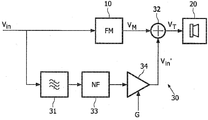
도2에 개요적으로 도시된 본 발명의 단지 예시적인 오디오 신호 적응 장치(30)는 오디오 주파수 맵핑 장치(10), 필터 유닛(31), 결합 유닛(32)을 포함하고 트랜스듀서를 포함하는 트랜스듀서 유닛(20)에 결합된다. 오디오 주파수 맵핑 장치(10)는 바람직하게는 도1의 장치(10)에 대응하지만, 이는 제1 필수적인 것이 아니라 오디오 주파수 범위를 제2 협 오디오 주파수 범위로 맵핑할 수 있는 다른 맵핑 장치들이 사용될 수 있다. The only exemplary audio
오디오 신호 적응 장치(30) 및 오디오 주파수 맵핑 장치(10)는 전형적인 오디오 주파수 범위, 즉 대략 20Hz에서 대략 15kHz 이상의 주파수 범위를 가질 수 있는 오디오 입력 신호(Vin)을 수신한다. 일부 애플리케이션들에서, 오디오 입력 신호(Vin)는 오디오 신호 적응 장치(30)로 공급되기 앞서 필터링됨으로, 더욱 제한된 대역폭을 가질 수 있다. 일부 애플리케이션들에서, 오디오 입력 신호(Vin)는 대략 20Hz 내지 200Hz 범위의 바스 주파수들로 제한될 수 있다. The audio
오디오 주파수 맵핑(FM) 장치(10)는 신호(VM)를 결합 장치(32)로 출력한다. 맵핑 장치(10)와 병렬로, 필터 유닛(31)이 배열되는데, 이는 또한 결합 유닛(32)에 결합된다. 필터 유닛(31)MD 입력 오디오 신호(Vin)을 수신하고 이 신호를 필터링하여 주파수 범위(도5의 제3 주파수 범위(III))를 선택한다. 그러므로, 전형적으로 필터 유닛(31)은 예를 들어 100 내지 150Hz의 범위의 통과 대역을 갖는 대역통과 필터를 포함할 것이다. 필터링된 오디오 입력 신호(Vin')는 결합 유닛(32)으로 공급되는데, 여기서 신호(VM)과 결합되어 트랜스듀서 신호(VT)를 발생시킨다. 결합 유닛(32)은 공지된 가산 유닛으로 구성될 수 있다. 트랜스듀서 신호(VT)는 트랜스듀서 유닛(20)으로 공급된다. The audio frequency mapping (FM)
트랜스듀서(21)는 상대적으로 협-대역 맵핑된 오디오 신호(VM) 및 필터링된 입력 신호(Vin')의 조합을 수신한다. 장치(10)는 예를 들어 (제1)주파수 범위 20 내지 100Hz를 55Hz를 중심으로 한 매우 좁은 범위에 맵핑할 수 있는 반면에, 필터 유닛(31)은 100 내지 150Hz의 (제3) 범위를 갖는 통과 대역을 갖는다. 이 예에서, 20Hz 내지 150Hz의 입력 신호 주파수들은 장치(30)에 의해 효율적으로 재생된다. 일부 실시예들에서, 필터 유닛(31)은 모든 통과 필터로 구성될 수 있지만, 대역 통과 필터가 바람직하다.
본 발명의 오디오 신호 적응 장치(30)의 대안적인 실시예는 개요적으로 도3 에 도시되어 있다. 도3의 실시예는 노치 필터(NF) 유닛(33) 및 이득 조정 유닛(34)을 더 포함하지만, 이들 둘 다는 필터 유닛(31)과 직렬로 배열된다. 도시된 실시예에서, 이들 둘 다는 필터 유닛(31) 및 결합 유닛(32) 간에 배열되지만, 이는 필수적인 것이 아니다.An alternative embodiment of the audio
노치 필터 유닛(33)은 도7과 관련하여 더욱 상세하게 후술되는 바와 같이 트랜스듀서 또는 트랜스듀서 유닛의 임의의 부가적인 공진 주파수들에 대응하는 주파수들을 제거하도록 작용한다. 이득 조정 유닛(34)은 조정가능한 이득 (G)을 갖는 제어된 증폭기로 구성되고 균형이잡힌 트랜스듀서 신호(VT)를 제공하기 위하여 신호(VM) 에 대한 신호 (Vin')의 진폭을 제어하도록 작용한다. 이득 조정 유닛(34)은 또한 노치 필터(33) 앞에 배열되거나 오디오 주파수 맵핑 유닛(10) 및 결합 유닛(32) 간에 배열될 수 있다. 도3의 실시예에서, 트랜스듀서 신호(VT)는 트랜스듀서 유닛(20)으로 공급되며, 이는 바람직하게는 공진 주파수 및/또는 헬름홀츠 주파소로 동작하도록 배열된다. The
도4의 비제한적인 예로만 도시된 트랜스듀서 유닛(20)은 라우드스피커와 같은 트랜스듀서(21)가 설치된 인클로저(22)를 포함한다. 도4의 실시예에서, 인클로저(22)는 제1 볼륨(V1) 및 제2 볼륨(V2) 각각과 뿐만 아니라 튜브(23)을 규정하는 2개의 챔버들을 포함한다. 볼륨(V1 및 V2)은 트랜스듀서(21)를 지지하는 파티션(26)에 의해 분할된다. 제1 볼륨(V1)은 튜브(23)와 개방 연통되어 있는 반면에서 제2 볼륨(V2)은 폐쇄되어 있다. 도시된 실시예에서, 인클로저(22)의 통합 부 분(integral part)을 형성하는 튜브(23)는 임의의 챔버로 돌출되지 않는 반면, 트랜스듀서는 튜브(23)와 마주본다. 다른 배열들이 가능한데, 예를 들어 트랜스듀서가 튜브(23)로부터 벗어나서 마주보는 배열이 가능하다는 것을 이해할 것이다. The
개방단(27)을 갖는 튜브(23)는 트랜스듀서 유닛(20)의 헬름홀츠 주파수를 결정하는데 기여하는 길이(L)과 내단면 표면적(S)을 갖는다. 표면적(S)은 트랜스듀서 유닛(20)의 유효 방사면을 규정한다. 도4에 도시된 튜브(23)는 직선이지만 대안적인 실시예들에서 튜브는 접혀지고, 접혀지며 및/또는 미로형 구조를 가질 수 있음으로, 콤팩트 디자인을 제공한다. 도시된 본 실시예들은 원래 크기대로 반드시 나타낼 필요가 없다는 점에 주의한다. The
대안적인 실시예(미도시)에서, 인클로저(22)는 단일 볼륨(V1)을 규정하는 단일 챔버만을 갖는다. 게다가, 트랜스듀서(전형적으로, 라우드스피커의 콘)(21)의 정면은 튜브(23)로부터 떨어져서 외향으로 마주본다. 그러나, 트랜스듀서는 또한 도4에 도시된 바와 같이 튜브(23)를 향하여 마주본다.In an alternative embodiment (not shown),
어느 한 실시예에서, 댐핑 재료는 인클로저에 제공되지 않으며, 튜브(23)는 상대적으로 긴것이 바람직한데, (제1) 볼륨(V1)은 상대적으로 작은 것이 바람직하다. 그러나, 일부 부가적인 실시예들에서, 소량의 댐핑 재료들이 제공될 수 있고 튜브(23)의 상대적인 디멘죤들 및 볼륨(V1)은 도시된 것과 다를 수 있다. In either embodiment, no damping material is provided in the enclosure, and the
도2 및 3과 관련하여 상술된 바와 같이, 주파수 맵핑 장치(10)는 중심 주파수(fW)를 갖는 신호(VM)을 발생시킨다. 본 발명에서, 인클로저(22)의 디멘죤들은 트랜스듀서 유닛(20)의 헬름홀츠 주파수(fH)가 신호(VM)의 주파수(fW)에 거의 동일하게 되도록 선택된다. 수학적으로 표현하면:As described above with reference to FIGS. 2 and 3, the
![]()
![]()
품질의 편차는 10% 미만, 바람직하게는 5% 미만, 더욱 바람직하게는 1% 미만이다. The variation in quality is less than 10%, preferably less than 5%, more preferably less than 1%.
헬름홀츠 주파수는 도4에 도시된 바와 같이 인클로저에 설치될 때 트랜스듀서의 전기 임피던스로 규정될 수 있다. 전기 임피던스(절대값)은 제1 공진 주파수 및 제2 공진 주파수에서 최대값에 도달한다. 공진 주파수들간에 전기 임피던스는 주파수(fH)에서 최소값에 도달한다. 이 주파수(fH)는 트랜스듀서 유닛의 헬름홀츠 주파수인데, 소위 반공진이 트랜스듀서 유닛(도4의 20)에서 발생되는 주파수가 되어, 트랜스듀서(21)의 (로컬) 최소 변위를 발생시킨다. 전기 임피던스는 부가적인 공진 주파수들에서 부가적으로 최대에 도달할 수 있지만, 이는 본 발명과 무관하다.The Helmholtz frequency may be defined as the electrical impedance of the transducer when installed in the enclosure as shown in FIG. The electrical impedance (absolute value) reaches a maximum at the first resonant frequency and the second resonant frequency. The electrical impedance between the resonant frequencies reaches a minimum at frequency f H. This frequency f H is the Helmholtz frequency of the transducer unit, the so-called anti-resonance being the frequency generated in the transducer unit (20 in FIG. 4), resulting in a (local) minimum displacement of the
오디오 주파수 범위의 바람직한 분포가 도5에 개요적으로 도시되어 있다. 제1 주파수 범위(I)가 비제한적인 예인 20Hz 내지 100Hz로 확장되어 도시되어 있다. 오디오 입력 신호(도2 및 3의 Vin)의 제1 주파수 범위(I)는 본 예에서 대략 50 내지 60Hz로 확장되는 제2 주파수 범위(II)로 맵핑된다. 제2 주파수 범위 II(도2 및 도3에서 신호(VM))가 제1 주파수 범위(I)보다 협소하거나 이에 포함된다는 것을 알 수 있다. A preferred distribution of the audio frequency range is shown schematically in FIG. The first frequency range I is shown extended to 20 Hz to 100 Hz, which is a non-limiting example. The first frequency range I of the audio input signal (V in of FIGS. 2 and 3) is mapped to a second frequency range II extending in this example to approximately 50 to 60 Hz. It can be seen that the second frequency range II (signal V M in FIGS. 2 and 3) is narrower than or included in the first frequency range I.
본 발명을 따르면, 트랜스듀서 유닛(도2 및 4의 20)은 제2 주파수 범위(II)뿐만 아니라 제3 주파수 범위(III)를 수신한다. 본 예에서, 제3 주파수 범위(III)는 100Hz에서 150Hz로 확장되어 귀중한 바스 주파수들을 부가하는 것을 알 수 있다. According to the invention, the
도5의 예에서, 제1 주파수 범위(I) 및 제3 주파수 범위(III)간에 중첩은 존재하지 않는다. 그러나, 이들 범위들의 필수적이 아니고 일부 중첩은 바람직하지 않을 수 있다. 그러나, 제2 주파수 범위(II) 및 제3 주파수 범위(III) 간의 임의의 중첩은 가령 -3dB 레벨가 같은 적어도 특정 진폭 레벨에서 피해지는 것이 바람직하다. In the example of FIG. 5, there is no overlap between the first frequency range I and the third frequency range III. However, some of these ranges are not essential and some overlap may be undesirable. However, it is preferred that any overlap between the second frequency range II and the third frequency range III is avoided at least at certain amplitude levels, for example the same -3 dB level.
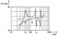
트랜스듀서 유닛(도4의 20)의 주파수 특성들은 도6 및 7에 도시된다. 도6에서, 트랜스듀서 유닛에 의해 발생되는 음압 레벨(SPL)은 (대수학적) 주파수의 함수로서 도시된다. 도4의 인클로저(22)와 같은 인클로저에 설치된 트랜스듀서인 트랜스듀서의 음압 레벨(SPL)은 그래프(A)로 도시될 수 있다. 그래프(B)는 인클로저 없이 트랜스듀서의 SPL을 표시하지만, 무한 배플에서 설치되고 콘 배치가 그래프(A)와 대응하는 시스템용과 동일하게 되도록 구동된다. The frequency characteristics of the
알 수 있는 바와 같이, 그래프(A)는 주파수 ***에서 (제1) 피크를 나타낸다. 이 때문에, 도5의 제2 주파수 범위(II)는 약 55Hz를 중심으로 한다. 따라서, 도5의 제1 주파수 범위(I)(20 내지 100Hz)의 주파수들은 주파수 범위(50 내지 60Hz)상에 맵핑되는데, 여기서 트랜스듀서는 (소정의 입력 전력에 대해서)최고 SPL을 갖는 다는 것을 또한 알 수 있다. 이는 트랜스듀서 인클로저의 볼륨(V1)(도4) 및 튜브(23)(또한 도4)에서 공진이 매우 낮은 콘 변위에서 높은 SPL을 야기시키는 트랜스듀서 유닛의 헬름홀츠 주파수이다. fH에서 그래프(A)의 피크 및 그래프(B)의 트라프(trough) 간의 SPL의 상당한 차이는 본 발명의 트랜스듀서 유닛의 명백한 이점이다.As can be seen, graph A shows the (first) peak at frequency ***. For this reason, the second frequency range II of Fig. 5 is centered at about 55 Hz. Thus, the frequencies of the first frequency range I (20-100 Hz) of FIG. 5 are mapped onto the frequency range 50-50 Hz, where the transducer has the highest SPL (for a given input power). It can also be seen. This is the Helmholtz frequency of the transducer unit where the resonance in the volume V1 of the transducer enclosure (FIG. 4) and the tube 23 (also FIG. 4) causes high SPL at very low cone displacement. The significant difference in SPL between the peak of graph A at t f and the trough of graph B at f H is a clear advantage of the transducer unit of the present invention.
부가적인 공진들이 대략 200Hz에서 발생된다는 것을 도6으로부터 알 수 있다. 임의의 이와 같은 공진들을 억제하기 위하여, 도3의 실시예는 대략 200Hz와 동일한 중심 주파수(노치 주파수 fn)을 갖는 노치 필터(33)를 포함한다.It can be seen from FIG. 6 that additional resonances occur at approximately 200 Hz. In order to suppress any such resonances, the embodiment of FIG. 3 includes a
도7의 그래프 C는 필터 유닛(31)의 대역 통과를 도시한다. 도시된 예에서, 통과 대역은 그래프(A)에서 실질적으로 제1 SPL 피크(fH에서) 및 제2 SPL 피크(fn에서)대략 70에서 150Hz로 확장된다. 따라서, 이 주파수 범위는 부가적으로 트랜스듀서로 공급되어, 재생된 주파수 범위를 확장시킨다. 트랜스듀서가 거의 주파수 fH와 같은 이 주파수 범위에서 유효하지 않을 때, 대응하는 신호(도3의 Vin')의 진폭은 상대적으로 증가(도3의 이득 조정 유닛(34))될 수 있는데, 그 이유는 필요로되는 콘 확장이 fH에서 이들 더 높은 주파수들에 있기 때문이다. Graph C of FIG. 7 shows the band pass of the
본 발명을 따른 오디오 시스템은 개요적으로 도8에 도시되어 있다. 오디오 처리 장치(3)는 증폭 유닛(50), 주파수 적응 장치(30) 및 프로세싱 유닛(40)을 포함하도록 도시되어 있다. 이 주파수 적응 장치(30) 및 프로세싱 유닛(40)은 병렬 로 배열된다.An audio system according to the invention is shown schematically in FIG. The
음원(2)에 의해 발생된 입력 신호(Vin)은 증폭되고나서 장치(30) 및 프로세싱 유닛(40)으로 공급되는 증폭 유닛(50)에 공급된다. 주파수 적응 장치(30)는 주파수 범위, 예를 들어, 바스 주파수 범위를 선택하고 또 다른 선택된 주파수 범위를 동일한 트랜스듀서 유닛(20)으로 공급하면서 이 주파수 범위를 (개요적으로 도시된) 제1 트랜스듀서 유닛(20)의 헬름홀츠 주파수로 맵핑된다. 프로세싱 유닛(40)은 모든 주파수들을 증폭하여 이 결과 신호를 (개요적으로 도시된) 제2 트랜스듀서 유닛(29)로 공급하는 증폭기를 더 포함할 수 있다. 부가적으로 또는 대안적으로, 프로세싱 유닛(40)은 특정 주파수들을 필터링하는 필터 및/또는 주파수 적응 장치(30) 및 트랜스듀서 유닛(20) 간에 배열된 증폭기를 포함할 수 있다.The input signal V in generated by the
스테레오 시스템 또는 5.1 시스템과 같은 다수의 채널 오디오 시스템의 경우에, 다수의 주파수 적응 장치들(30)은 제공될 수 있다. 대안적으로, 단일 주파수 적응 장치(30)는 2개 이상의 채널들에 의해 공유될 수 있는데, (바스) 신호들은 주파수 적응 장치(30)에 의해 적응되어야 하는 공유 신호를 발생시키도록 부가된다.In the case of a multichannel audio system, such as a stereo system or a 5.1 system, multiple
바람직한 실시예에서, 프로세싱 유닛(40)은 특히 특정 시간 인스턴트에서 제1 트랜스듀서 유닛(20)의 음압이 거의 제2 트랜스듀서 유닛(29)의 음압과 거의 동일하게 되는 방식으로 제2 트랜스듀서 유닛(29)에 공급되는 신호를 지연시키는 지연 소자들을 포함한다. 이 실시예에서, 프로세싱 유닛(40)은 장치(10)에 의해 발생되는 어떠한 지연들과 동일하도록 지연들을 발생시킨다.In a preferred embodiment, the
제1 트랜스듀서 유닛(20)은 바람직하게는 헬름홀츠 주파수에서 동작하도록 디자인된 본 발명을 따른 트랜스듀서 유닛인 반면에, 제2 트랜스듀서 유닛(29)은 하나 이상의 트랜스듀서들을 갖는 종래의 트랜스듀서 유닛일 수 있다.The
음원(2)은 무선 튜너, CD 또는 CD 플레이어, MP3 또는 AAC 플레이어, 인터넷 단말기, 및/또는 적절한 오디오 저장 수단을 갖는 컴퓨터와 같은 임의의 적절한 음원으로 구성될 수 있다. The
본 발명은 (평면) 텔레비젼 장치, 텔레비젼 수신기 장치들, 셋톱 박스 장치들, 위성 수신기 장치들, 홈 사운드 시스템들, 전문적인 음 시스템들, 및 차량 음 시스템들을 포함하지만 이로 제한되지 않는다.The present invention includes, but is not limited to, (planar) television devices, television receiver devices, set top box devices, satellite receiver devices, home sound systems, professional sound systems, and vehicle sound systems.
본 발명은 협 맵핑된 주파수 범위에서 동작하는 트랜스듀성 유닛에 의해 재생되는 음질이 주파수 맵핑된 오디오 신호에 원래 오디오 신호의 부분을 첨가함으로써 상당히 개선될 수 있다는 통찰을 토대로 한다. The present invention is based on the insight that sound quality reproduced by a transdue unit operating in a narrow mapped frequency range can be significantly improved by adding a portion of the original audio signal to the frequency mapped audio signal.
본 문서에서 사용되는 어떤 용어들은 본 발명의 범위를 제한하는 것으로서 해서되지 않아야 한다는 점에 주의한다. 특히, 단어 "포함하다" 및 "포함하는"은 특별히 언급되지 않은 어떠한 소자들을 배제하는 것을 의미하지 않는다. 단일(회로) 소자들은 다수의 (회로) 소자들로 또는 이들의 등가물들로 대체될 수 있다. Note that some terms used in this document should not be taken as limiting the scope of the present invention. In particular, the words "comprise" and "comprising" do not mean excluding any elements not specifically mentioned. Single (circuit) elements can be replaced with multiple (circuit) elements or their equivalents.
당업자는 상술된 실시예들로 제한되지 않고 많은 수정들 및 변경들이 첨부한 청구범위에 규정된 바와 같은 본 발명의 범위를 벗어남이 없이 이루어질 수 있다는 것 이해할 것이다. Those skilled in the art will understand that many modifications and changes can be made without departing from the scope of the invention as defined in the appended claims, without being limited to the embodiments described above.
Claims (24)
Applications Claiming Priority (2)
| Application Number | Priority Date | Filing Date | Title |
|---|---|---|---|
| EP06100928.8 | 2006-01-27 | ||
| EP06100928 | 2006-01-27 |
Publications (1)
| Publication Number | Publication Date |
|---|---|
| KR20080098388A true KR20080098388A (en) | 2008-11-07 |
Family
ID=38162292
Family Applications (1)
| Application Number | Title | Priority Date | Filing Date |
|---|---|---|---|
| KR1020087020967A Withdrawn KR20080098388A (en) | 2006-01-27 | 2007-01-23 | Efficient Audio Playback |
Country Status (6)
| Country | Link |
|---|---|
| US (1) | US20100226508A1 (en) |
| EP (1) | EP1982558A2 (en) |
| JP (1) | JP2009524967A (en) |
| KR (1) | KR20080098388A (en) |
| CN (1) | CN101375629A (en) |
| WO (1) | WO2007086000A2 (en) |
Families Citing this family (5)
| Publication number | Priority date | Publication date | Assignee | Title |
|---|---|---|---|---|
| US20080226088A1 (en) * | 2005-09-20 | 2008-09-18 | Koninklijke Philips Electronics, N.V. | Audio Transducer System |
| US8934643B2 (en) | 2008-04-09 | 2015-01-13 | Koninklijke Philips N.V. | Generation of a drive signal for sound transducer |
| US9516406B2 (en) * | 2011-12-20 | 2016-12-06 | Nokia Technologies Oy | Portable device with enhanced bass response |
| US9247342B2 (en) | 2013-05-14 | 2016-01-26 | James J. Croft, III | Loudspeaker enclosure system with signal processor for enhanced perception of low frequency output |
| CN110012674A (en) * | 2016-08-05 | 2019-07-12 | 萨巴帕克公司 | The transducer system of sense of touch is provided |
Family Cites Families (5)
| Publication number | Priority date | Publication date | Assignee | Title |
|---|---|---|---|---|
| CN1274184C (en) * | 2001-09-21 | 2006-09-06 | 西门子公司 | Method and apparatus for controlling bass playback of an audio signal in an electroacoustic transducer |
| IL154745A0 (en) * | 2003-03-04 | 2003-10-31 | Medit Medical Interactive Tech | Method and system for acoustic communication |
| WO2005027569A1 (en) * | 2003-09-16 | 2005-03-24 | Koninklijke Philips Electronics N.V. | High efficiency audio reproduction |
| KR101104920B1 (en) * | 2003-09-16 | 2012-01-12 | 코닌클리케 필립스 일렉트로닉스 엔.브이. | Audio frequency range adaptation |
| US7218747B2 (en) * | 2003-12-05 | 2007-05-15 | Nick Huffman | Externally ported loudspeaker enclosure |
-
2007
- 2007-01-23 KR KR1020087020967A patent/KR20080098388A/en not_active Withdrawn
- 2007-01-23 JP JP2008551926A patent/JP2009524967A/en not_active Withdrawn
- 2007-01-23 CN CNA2007800034932A patent/CN101375629A/en active Pending
- 2007-01-23 WO PCT/IB2007/050224 patent/WO2007086000A2/en not_active Ceased
- 2007-01-23 EP EP07700665A patent/EP1982558A2/en not_active Withdrawn
- 2007-01-23 US US12/161,811 patent/US20100226508A1/en not_active Abandoned
Also Published As
| Publication number | Publication date |
|---|---|
| EP1982558A2 (en) | 2008-10-22 |
| WO2007086000A2 (en) | 2007-08-02 |
| US20100226508A1 (en) | 2010-09-09 |
| CN101375629A (en) | 2009-02-25 |
| JP2009524967A (en) | 2009-07-02 |
| WO2007086000A3 (en) | 2007-11-01 |
Similar Documents
| Publication | Publication Date | Title |
|---|---|---|
| CN101461254B (en) | Bandpass transducer system with long ports | |
| US9281795B2 (en) | Acoustic signal processing apparatus | |
| RU2568314C2 (en) | Amplifier and correction of amplitude-frequency response | |
| JP6522122B2 (en) | Mechanically operated panel sound system | |
| US20070071255A1 (en) | Adaptive Sound Reproduction | |
| US9949057B2 (en) | Stereo and filter control for multi-speaker device | |
| US8386242B2 (en) | Method, medium and apparatus enhancing a bass signal using an auditory property | |
| JP2002524996A5 (en) | ||
| EA002858B1 (en) | Capacitor-less crossover network for electro-acoustic loudspeakers | |
| US20070030983A1 (en) | High efficiency audio reproduction | |
| KR20080098388A (en) | Efficient Audio Playback | |
| KR101104920B1 (en) | Audio frequency range adaptation | |
| US6310959B1 (en) | Tuned order crossover network for electro-acoustic loudspeakers | |
| US20100246854A1 (en) | Sound reproduction | |
| JP6898538B1 (en) | Speaker system | |
| WO2001078447A1 (en) | Ultra bass ii | |
| JPH04371100A (en) | Sound equipment with reverberation adding device | |
| CA2525388A1 (en) | Complementary-pair equalizer | |
| KR20000031324A (en) | Bass reproduction compensating circuit | |
| KR20000013762U (en) | Audio noise canceller | |
| KR20000013764U (en) | Audio booming eliminator |
Legal Events
| Date | Code | Title | Description |
|---|---|---|---|
| PA0105 | International application |
St.27 status event code: A-0-1-A10-A15-nap-PA0105 |
|
| PG1501 | Laying open of application |
St.27 status event code: A-1-1-Q10-Q12-nap-PG1501 |
|
| PC1203 | Withdrawal of no request for examination |
St.27 status event code: N-1-6-B10-B12-nap-PC1203 |
|
| WITN | Application deemed withdrawn, e.g. because no request for examination was filed or no examination fee was paid | ||
| R18-X000 | Changes to party contact information recorded |
St.27 status event code: A-3-3-R10-R18-oth-X000 |
|
| PN2301 | Change of applicant |
St.27 status event code: A-3-3-R10-R13-asn-PN2301 St.27 status event code: A-3-3-R10-R11-asn-PN2301 |
|
| R18-X000 | Changes to party contact information recorded |
St.27 status event code: A-3-3-R10-R18-oth-X000 |
|
| R18-X000 | Changes to party contact information recorded |
St.27 status event code: A-3-3-R10-R18-oth-X000 |
|
| R18-X000 | Changes to party contact information recorded |
St.27 status event code: A-3-3-R10-R18-oth-X000 |
|
| R18 | Changes to party contact information recorded |
Free format text: ST27 STATUS EVENT CODE: A-3-3-R10-R18-OTH-X000 (AS PROVIDED BY THE NATIONAL OFFICE) |
|
| R18-X000 | Changes to party contact information recorded |
St.27 status event code: A-3-3-R10-R18-oth-X000 |