KR20080098276A - Interactive system such as insects and its operation method - Google Patents
Interactive system such as insects and its operation method Download PDFInfo
- Publication number
- KR20080098276A KR20080098276A KR1020070043769A KR20070043769A KR20080098276A KR 20080098276 A KR20080098276 A KR 20080098276A KR 1020070043769 A KR1020070043769 A KR 1020070043769A KR 20070043769 A KR20070043769 A KR 20070043769A KR 20080098276 A KR20080098276 A KR 20080098276A
- Authority
- KR
- South Korea
- Prior art keywords
- information
- insect
- signal
- lamp
- alarm
- Prior art date
- Legal status (The legal status is an assumption and is not a legal conclusion. Google has not performed a legal analysis and makes no representation as to the accuracy of the status listed.)
- Ceased
Links
- 241000238631 Hexapoda Species 0.000 title claims abstract description 290
- 230000002452 interceptive effect Effects 0.000 title claims abstract description 94
- 238000000034 method Methods 0.000 title claims description 116
- 241000607479 Yersinia pestis Species 0.000 claims abstract description 89
- 241000270322 Lepidosauria Species 0.000 claims abstract description 8
- 239000000077 insect repellent Substances 0.000 claims description 123
- 230000015654 memory Effects 0.000 claims description 59
- 238000007689 inspection Methods 0.000 claims description 55
- 238000004891 communication Methods 0.000 claims description 34
- 239000005667 attractant Substances 0.000 claims description 33
- 230000031902 chemoattractant activity Effects 0.000 claims description 32
- 230000005540 biological transmission Effects 0.000 claims description 25
- 230000008859 change Effects 0.000 claims description 21
- 239000002917 insecticide Substances 0.000 claims description 21
- 238000004458 analytical method Methods 0.000 claims description 17
- 230000000694 effects Effects 0.000 claims description 17
- 239000000575 pesticide Substances 0.000 claims description 12
- 238000001514 detection method Methods 0.000 claims description 10
- 241000938605 Crocodylia Species 0.000 claims description 8
- 238000012545 processing Methods 0.000 claims description 7
- 239000000853 adhesive Substances 0.000 claims description 5
- 230000001070 adhesive effect Effects 0.000 claims description 5
- 230000003287 optical effect Effects 0.000 claims description 5
- 239000004973 liquid crystal related substance Substances 0.000 claims description 4
- 238000001816 cooling Methods 0.000 claims description 3
- 230000002159 abnormal effect Effects 0.000 claims description 2
- 230000000903 blocking effect Effects 0.000 claims description 2
- 230000003247 decreasing effect Effects 0.000 claims description 2
- 239000003795 chemical substances by application Substances 0.000 claims 1
- 230000008901 benefit Effects 0.000 abstract description 4
- 230000008569 process Effects 0.000 description 8
- 230000005856 abnormality Effects 0.000 description 5
- 238000010586 diagram Methods 0.000 description 5
- 230000007613 environmental effect Effects 0.000 description 5
- 230000006870 function Effects 0.000 description 4
- 238000013461 design Methods 0.000 description 3
- 238000011084 recovery Methods 0.000 description 3
- 238000011160 research Methods 0.000 description 3
- 241000255925 Diptera Species 0.000 description 2
- 241001465754 Metazoa Species 0.000 description 2
- 230000001133 acceleration Effects 0.000 description 2
- 230000006378 damage Effects 0.000 description 2
- 238000005401 electroluminescence Methods 0.000 description 2
- 230000010355 oscillation Effects 0.000 description 2
- 239000002699 waste material Substances 0.000 description 2
- 230000008033 biological extinction Effects 0.000 description 1
- 230000004397 blinking Effects 0.000 description 1
- 239000000428 dust Substances 0.000 description 1
- 230000005611 electricity Effects 0.000 description 1
- 210000003608 fece Anatomy 0.000 description 1
- 238000005286 illumination Methods 0.000 description 1
- 230000000749 insecticidal effect Effects 0.000 description 1
- 244000144972 livestock Species 0.000 description 1
- 239000000463 material Substances 0.000 description 1
- 230000007246 mechanism Effects 0.000 description 1
- 238000012986 modification Methods 0.000 description 1
- 230000004048 modification Effects 0.000 description 1
- 238000011017 operating method Methods 0.000 description 1
- 238000013021 overheating Methods 0.000 description 1
- 244000052769 pathogen Species 0.000 description 1
- 230000000737 periodic effect Effects 0.000 description 1
- ZRHANBBTXQZFSP-UHFFFAOYSA-M potassium;4-amino-3,5,6-trichloropyridine-2-carboxylate Chemical compound [K+].NC1=C(Cl)C(Cl)=NC(C([O-])=O)=C1Cl ZRHANBBTXQZFSP-UHFFFAOYSA-M 0.000 description 1
- 230000009467 reduction Effects 0.000 description 1
- 230000001846 repelling effect Effects 0.000 description 1
- 239000000779 smoke Substances 0.000 description 1
- 230000005236 sound signal Effects 0.000 description 1
- 239000004753 textile Substances 0.000 description 1
- XLYOFNOQVPJJNP-UHFFFAOYSA-N water Substances O XLYOFNOQVPJJNP-UHFFFAOYSA-N 0.000 description 1
Images


Classifications
-
- A—HUMAN NECESSITIES
- A01—AGRICULTURE; FORESTRY; ANIMAL HUSBANDRY; HUNTING; TRAPPING; FISHING
- A01M—CATCHING, TRAPPING OR SCARING OF ANIMALS; APPARATUS FOR THE DESTRUCTION OF NOXIOUS ANIMALS OR NOXIOUS PLANTS
- A01M1/00—Stationary means for catching or killing insects
- A01M1/14—Catching by adhesive surfaces
- A01M1/145—Attracting and catching insects using combined illumination or colours and adhesive surfaces
-
- A—HUMAN NECESSITIES
- A01—AGRICULTURE; FORESTRY; ANIMAL HUSBANDRY; HUNTING; TRAPPING; FISHING
- A01M—CATCHING, TRAPPING OR SCARING OF ANIMALS; APPARATUS FOR THE DESTRUCTION OF NOXIOUS ANIMALS OR NOXIOUS PLANTS
- A01M2200/00—Kind of animal
- A01M2200/01—Insects
- A01M2200/012—Flying insects
-
- Y—GENERAL TAGGING OF NEW TECHNOLOGICAL DEVELOPMENTS; GENERAL TAGGING OF CROSS-SECTIONAL TECHNOLOGIES SPANNING OVER SEVERAL SECTIONS OF THE IPC; TECHNICAL SUBJECTS COVERED BY FORMER USPC CROSS-REFERENCE ART COLLECTIONS [XRACs] AND DIGESTS
- Y10—TECHNICAL SUBJECTS COVERED BY FORMER USPC
- Y10S—TECHNICAL SUBJECTS COVERED BY FORMER USPC CROSS-REFERENCE ART COLLECTIONS [XRACs] AND DIGESTS
- Y10S43/00—Fishing, trapping, and vermin destroying
Landscapes
- Life Sciences & Earth Sciences (AREA)
- Pest Control & Pesticides (AREA)
- Engineering & Computer Science (AREA)
- Insects & Arthropods (AREA)
- Wood Science & Technology (AREA)
- Zoology (AREA)
- Environmental Sciences (AREA)
- Catching Or Destruction (AREA)
Abstract
비래해충을 포획하는 포충등의 인터렉티브 시스템에 있어서, 원격지에 위치한 별도의 관제센터와 포충등간의 정보를 서로 송수신하고 제어하는 포충등의 인터렉티브 시스템이 개시된다. 상기 포충등과 상기 관제센터는 각각 원격지에 떨어져 별도로 위치하며, 서로 정보를 송수신하도록 구비되어 인터렉티브한 작업을 진행할 수 있으며, 상기 포충등에 구비된 센서에서 감지된 제 1정보를 상기 관제센터로 송신하고, 상기 관제센터는 상기 제 1정보를 수신하여, 이에 대응하는 제 2정보를 생성 및 상기 포충등으로 재송신하고, 상기 포충등은 상기 제 2정보를 수신하여 제어신호를 생성하고, 이를 바탕으로 상기 포충등을 제어하는 작업을 진행하여 유기적으로 원격으로 인터렉티브 시스템이 실시간으로 운영되도록 구성된다. 따라서, 상기 포충등과 상기 관제센터는 원격지에 별도로 위치하면서 서로 제 1 및 제 2정보를 송수신하고 이에 따른 제어신호를 생성하여 실시간으로 제어되도록 함으로써 효율적인 원격 실시간 관리 및 제어가 가능하게 하는 이점이 있다.In an interactive system such as a reptile for capturing a fly pest, an interactive system such as a reptile for transmitting and receiving information between a separate control center and a reptile and the like located at a remote site and controlling each other is disclosed. The insect lamp and the control center are separately located at a remote location, and are provided to transmit and receive information with each other to perform an interactive operation, and transmit the first information detected by the sensor provided in the insect lamp to the control center; The control center receives the first information, generates second information corresponding to the first information, and retransmits the information to the insect trap, and the insect insect lamp receives the second information to generate a control signal. It is configured to operate the interactive system in real time remotely by proceeding to control the insects. Therefore, the insect lamp and the control center are located at a remote location, and transmits and receives the first and second information with each other, and generates a control signal according to it has the advantage of enabling efficient remote real-time management and control .
Description
도 1은 종래의 포충등을 도시한 사시도이다.1 is a perspective view showing a conventional insect lamp.
도 2는 본 발명에 따른 포충등의 인터렉티브 시스템을 개략적으로 도식화하여 나타낸 것이다.2 is a schematic diagram illustrating an interactive system such as an insect insect according to the present invention.
도 3은 본 발명에 따른 포충등의 도어부가 닫힌 상태를 도시한 사시도이다.Figure 3 is a perspective view showing a state in which the door portion of the insect repellent lamp according to the invention is closed.
도 4는 도 3에 도시된 포충등의 도어부가 열린 상태를 도시한 사시도이다.FIG. 4 is a perspective view illustrating a state in which a door part such as the insect repellent lamp shown in FIG. 3 is opened.
도 5는 도 5는 본 발명의 제 1실시예에 따른 포충등의 인터렉티브 시스템의 구성을 도시한 구성도이다.5 is a block diagram showing the configuration of an interactive system, such as insects in accordance with the first embodiment of the present invention.
도 6은 본 발명의 제 1실시예에 따른 포충등의 인터렉티브 시스템의 운용방법을 도시한 순서도이다.6 is a flowchart illustrating a method of operating an interactive system such as a insect repellent according to the first embodiment of the present invention.
도 7은 본 발명의 제 2실시예에 따른 포충등의 인터렉티브 시스템을 도시한 구성도이다.7 is a block diagram showing an interactive system such as a insect repellent according to a second embodiment of the present invention.
도 8은 본 발명의 제 2실시예에 따른 포충등의 인터렉티브 시스템의 운용방법을 도시한 순서도이다.8 is a flowchart illustrating a method of operating an interactive system such as an insect insect, according to a second embodiment of the present invention.
도 9는 본 발명의 실시예에 따른 제 1정보와 제 2정보 및 제어신호의 흐름 과 생성을 일반적으로 나타낸 순서도이다.9 is a flow chart generally showing the flow and generation of the first information, the second information and the control signal according to an embodiment of the present invention.
도 10은 상기 제 1정보(Si)가 등 밝기 정보(S1)인 경우에 상기 제 2정보(Aij)를 생성하는 도 9에 도시된 F4단계를 설명한 순서도이다.10 is a flowchart illustrating the steps of F4 shown in Figure 9 to generate the second information (A ij) in the case of the first information (S i) the brightness information (S 1).
도 11은 상기 제 1정보(Si)가 포충등 내, 외부 온도정보(S2)인 경우에 상기 제 2정보(Aij)를 생성하는 도 9에 도시된 F4단계를 설명한 순서도이다.11 is a flowchart illustrating the steps of F4 shown in Figure 9 to generate the second information (A ij) in the case of the first information (S i) is pochung including internal and external temperature information (S 2).
도 12는 상기 제 1정보(Si)가 풍속 정보(S3)인 경우에 상기 제 2정보(Aij)를 생성하는 도 9에 도시된 F4단계를 설명한 순서도이다.12 is a flowchart illustrating the steps of F4 shown in Figure 9 to generate the second information (A ij) in the case of the first information (S i) a wind speed information (S 3).
도 13은 상기 제 1정보(Si)가 강우량정보(S4)인 경우에 상기 제 2정보(Aij)를 생성하는 도 9에 도시된 F4단계를 설명한 순서도이다.13 is a flowchart illustrating the steps of F4 shown in Figure 9 to generate the second information (A ij) in the case of the first information (S i) the rainfall information (S 4).
도 14는 상기 제 1정보(Si)가 도어부 개폐 정보(S5)인 경우에 상기 제 2정보(Aij)를 생성하는 도 9에 도시된 F4단계를 설명한 순서도이다.14 is a flow chart for explaining a step of F4 shown in Figure 9 to generate the second information (A ij) in the case of the first information (S i) of the door opening and closing unit information (S 5).
도 15는 상기 제 1정보(Si)가 포획량 정보(S6)인 경우에 상기 제 2정보(Aij)를 생성하는 도 9에 도시된 F4단계를 설명한 순서도이다.15 is a flow chart for explaining a step of F4 shown in Figure 9 to generate the second information (A ij) in the case of the first information (S i) the catch information (S 6).
도 16은 상기 제 1정보(Si)가 포획 면적 정보(S7)인 경우에 상기 제 2정보(Aij)를 생성하는 도 9에 도시된 F4단계를 설명한 순서도이다.Figure 16 is a flow chart for explaining a step of F4 shown in Figure 9 to generate the second information (A ij) in the case of the first information (S i) a capture area information (S 7).
도 17은 상기 제 1정보(Si)가 수납용기잔량 정보(S8)인 경우에 상기 제 2정 보(Aij)를 생성하는 도 9에 도시된 F4단계를 설명한 순서도이다.17 is a flow chart for explaining a step of F4 shown in Figure 9 to generate the second information (A ij) in the case of the first information (S i) a receiving container remaining amount information (S 8).
도 18은 상기 제 1정보(Si)가 수납용기 교체잔여주기 정보(S9)인 경우에 상기 제 2정보(Aij)를 생성하는 도 9에 도시된 F4단계를 설명한 순서도이다.18 is a flow chart for explaining a step of F4 shown in Figure 9 to generate the second information (A ij) in the case of the first information (S i) a storage container to replace the remaining period information (S 9).
도 19는 상기 제 1정보(Si)가 끈끈이 잔량 정보(S10)인 경우에 상기 제 2정보(Aij)를 생성하는 도 9에 도시된 F4단계를 설명한 순서도이다.19 is a flow chart for explaining a step of F4 shown in Figure 9 to generate the second information (A ij) in the case of the first information (S i) a sticky-level information (S10).
도 20은 상기 제 1정보(Si)가 끈끈이 교체잔여주기 정보(S11)인 경우에 상기 제 2정보(Aij)를 생성하는 도 9에 도시된 F4단계를 설명한 순서도이다.20 is a flow chart for explaining a step of F4 shown in Figure 9 to generate the second information (A ij) in the case of the first information (S i) a sticky residue replacement period information (S 11).
도 21은 상기 제 1정보(Si)가 해충포획회수 정보(S12)인 경우에 상기 제 2정보(Aij)를 생성하는 도 9에 도시된 F4단계를 설명한 순서도이다.21 is a flow chart for explaining a step of F4 shown in Figure 9 to generate the second information (A ij) in the case of the first information (S i) a pest trap number information (S 12).
도 22는 상기 제 1정보(Si)가 포충등 진입 해충 감지회수 정보(S13)인 경우에 상기 제 2정보(Aij)를 생성하는 도 9에 도시된 F4단계를 설명한 순서도이다.22 is a flow chart for explaining a step of F4 shown in Figure 9 to generate the second information (A ij) in the case of the first information (S i) enters pest detection count information (S 13) including pochung.
도 23은 상기 제 1정보(Si)가 보조전원장치 전압정보(S14)인 경우에 상기 제 2정보(Aij)를 생성하는 도 9에 도시된 F4단계를 설명한 순서도이다.Figure 23 is a flow chart illustrating the steps of F4 shown in Figure 9 to generate the second information (A ij) in the case of the first information (S i) an auxiliary power supply voltage information (S 14).
도 24는 상기 제 1정보(Si)가 메모리잔량 정보(S15)인 경우에 상기 제 2정보(Aij)를 생성하는 도 9에 도시된 F4단계를 설명한 순서도이다.24 is a flow chart for explaining a step of F4 shown in Figure 9 to generate the second information (A ij) in the case of the first information (S i), a memory remaining amount information (S 15).
도 25는 상기 제 1정보(Si)가 유인제 잔량 정보(S16)인 경우에 상기 제 2정보(Aij)를 생성하는 도 9에 도시된 F4단계를 설명한 순서도이다.25 is a flow chart for explaining a step of F4 shown in Figure 9 to generate the second information (A ij) in the case of the first information (S i) an attractant level information (S 16).
도 26은 상기 제 1정보(Si)가 유인제 교체잔여주기 정보(S17)인 경우에 상기 제 2정보(Aij)를 생성하는 도 9에 도시된 F4단계를 설명한 순서도이다.26 is a flow chart for explaining a step of F4 shown in Figure 9 to generate the second information (A ij) in the case of the first information (S i) an attractant replace remaining period information (S 17).
도 27은 상기 제 1정보(Si)가 살충제 잔량 정보(S18)인 경우에 상기 제 2정보(Aij)를 생성하는 도 9에 도시된 F4단계를 설명한 순서도이다.27 is a flow chart for explaining a step of F4 shown in Figure 9 to generate the second information (A ij) in the case of the first information (S i) an insecticide remaining amount information (S 18).
도 28은 상기 제 1정보(Si)가 살충제 교체잔여주기 정보(S19)인 경우에 상기 제 2정보(Aij)를 생성하는 도 9에 도시된 F4단계를 설명한 순서도이다.28 is a flow chart for explaining a step of F4 shown in Figure 9 to generate the second information (A ij) in the case of the first information (S i) a pesticide residual replacement period information (S 19).
도 29는 상기 제 1정보(Si)가 작동상태정보(S20)인 경우에 상기 제 2정보(Aij)를 생성하는 도 9에 도시된 F4단계를 설명한 순서도이다.29 is a flow chart for explaining a step of F4 shown in Figure 9 to generate the second information (A ij) in the case of the first information (S i) is the operating state information (S 20).
도 30은 상기 제 1정보(Si)가 점검정보(S21)인 경우에 상기 제 2정보(Aij)를 생성하는 도 9에 도시된 F4단계를 설명한 순서도이다.30 is a flow chart for explaining a step of F4 shown in Figure 9 to generate the second information (A ij) in the case of the first information (S i) to check information (S 21).
도 31은 상기 제 1정보(Si)가 입구의 폐쇄 후 경과시간 정보(S22)인 경우에 상기 제 2정보(Aij)를 생성하는 도 9에 도시된 F4단계를 설명한 순서도이다.31 is a flow chart for explaining a step of F4 shown in Figure 9 to generate the second information (A ij) in the case of the first information (S i) is the elapsed time information (S 22) after closing of the inlet.
도 32는 상기 제 1정보(Si)가 상기 포충등의 내, 외부 습도정보(S22)인 경우에 상기 제 2정보(Aij)를 생성하는 도 9에 도시된 F4단계를 설명한 순서도이다.32 is a flowchart for explaining an the F4 stage shown in Figure 9 to generate the first information (S i) is the second information (A ij) in the case of internal and external humidity information (S 22), such as the pochung .
도 33은 본 발명의 제 3실시예에 따른 포충등의 인터렉티브 시스템을 도시한 구성도이다.33 is a block diagram showing an interactive system such as an insect repellent lamp according to a third embodiment of the present invention.
도 34는 도 33에 도시된 포충등의 인터렉티브 시스템의 운용방법을 도시한 순서도이다.FIG. 34 is a flowchart illustrating a method of operating an interactive system such as the insect reptile shown in FIG. 33.
<도면의 주요 부분에 대한 부호의 설명> <Explanation of symbols for main parts of the drawings>
80:본체부 82:끈끈이80: The body part 82: Sticky
83:유인등 86:통신모듈83: attraction light 86: communication module
90:도어부 91:표시부90: door part 91: display part
92:개방부 93:해충진입부92: Opening part 93: Pest entry part
100:포충등 110:센서100: insect light 110: sensor
120:제 1송신유닛 130:제 2수신유닛120: first sending unit 130: second receiving unit
140:포충등 제어유닛 145:제어기140: insect control unit 145: controller
150:제어기 170:메모리유닛150: controller 170: memory unit
190:입력유닛 200:통신망190: input unit 200: communication network
300:관제센터 310:제1수신유닛300: control center 310: first receiving unit
320:서버유닛 330:관제유닛320: server unit 330: control unit
335:해석유닛 350:제 2송신유닛335: Analysis unit 350: Second sending unit
400:집중기 410:제 1송수신유닛400: concentrator 410: first transmitting and receiving unit
420:스토리지 유닛 430:제 2송수신유닛420: storage unit 430: second transmission and reception unit
450:수치입력기 425:범용직렬버스450: numeric input unit 425: universal serial bus
본 발명은 포충등의 인터렉티브 시스템 및 이의 운용방법에 관한 것으로서, 보다 상세하게는 센서, 제 1송신유닛, 제 2수신유닛 및 포충등 제어유닛을 구비한 포충등과 제 1수신유닛, 관제유닛, 제 2송신유닛을 구비하고 상기 포충등과 원격으로 떨어진 별도의 관제센터를 포함하며, 통신망을 통해 상기 포충등과 관제센터간의 정보 송수신이 가능하고, 이에 따라 원격지의 관제센터에서 상기 포충등의 정보를 수집하고 제어할 수 있는 포충등의 인터렉티브 시스템 및 이의 운용방법에 관한 것이다.The present invention relates to an interactive system such as a insect repellent and a method of operating the same, and more particularly, a insect repellent lamp having a sensor, a first transmitting unit, a second receiving unit, and an insect feeding control unit, and a first receiving unit, a control unit, It includes a second control unit and includes a separate control center remote from the insects, etc., and it is possible to transmit and receive information between the insects and the control center through a communication network, and thus the information of the insects in the remote control center The present invention relates to an interactive system such as an insect repellent, which can collect and control the insects and a method of operating the same.
경제가 발전함에 따라 생활수준이 점점 향상되면서, 과거 무심코 지나쳤던 해충들은 이제 모든 사람들에게 있어서 강한 경계 대상이 되고 있다. 그러나 산업화 또는 공업화로 인해 많은 양의 쓰레기가 발생하고 있으며, 이에 따라 해충은 점점 더 증가하는 추세에 있다.As the economy develops, living standards are gradually improving, and pests that have been overlooked in the past are now becoming a vigilant point for everyone. However, due to industrialization or industrialization, a large amount of waste is generated, and accordingly, pests are increasing.
본 명세서에서 해충이라 함은 인간 및 가축에게 해를 주는 곤충이나 동물을 총칭하는 개념이며, 특히 비래해충은 파리, 모기, 나방, 하루살이 등 날아 다니는 해충을 말한다. 상기 비래해충은 사람이 그 개체를 방제하는 수보다 산란하여 발생하는 수가 더 많으며 온 공간을 날아다니며 언제 어디서나 유입되므로 그 방제가 더욱 중요시되고 있다.In the present specification, the term pest refers to insects or animals that collectively harm humans and livestock. In particular, insect pests refer to insects such as flies, mosquitoes, moths, and insects that fly. The insect pests are more likely to be spawned than humans control the individual, and the control is more important because the insects fly through the whole space and are introduced anywhere anytime.
또한, 이런 해충들은 음식이나 직물들을 갉아 먹어 생활에 적잖은 피해를 주고 있으며, 배설물들로 인해 인체에 해로운 병원균을 옮기기도 한다. 근래에는 이러한 해충이 오염된 환경으로 인하여 증가하는 추세에 있어서, 해충 제거가 큰 문제로 대두되고 있다. 따라서 집, 회사 혹은 지역 사회에서는 갖가지 방법으로 해충을 제거하는 노력을 하고 있다.In addition, these pests eat food and textiles, causing considerable damage to life, and excreta carry pathogens that are harmful to the human body. In recent years, such pests are increasing due to the polluted environment, the pest removal is a big problem. Therefore, homes, businesses or communities are trying to get rid of pests in various ways.
종래에는 비래해충을 제거하는 기구가 여러 가지가 있으나, 그 중에서 대체적으로 자외선과 같은 빛으로 비래해충을 유인하여 포획하는 포충등이 가장 많이 통용되고 있다.Conventionally, there are a number of mechanisms for removing adventitious pests, among which the insects that attract and capture the adventitious pest with light such as ultraviolet rays are most commonly used.
도 1을 참조하여 종래 포충등의 개략적인 형상과 작동을 설명하면 다음과 같다. 도 1은 종래의 포충등을 나타낸 사시도이다.Referring to Figure 1 describes the schematic shape and operation of a conventional insect lamp as follows. 1 is a perspective view showing a conventional insect lamp.
이에 도시된 바와 같이, 일반적으로 포충등(10)은 유인등(13)과 살충수단(15) 및 해충수집수단(17)을 포함한다. 여기서, 상기 포충등(10)의 작동을 설명하면, 먼저, 상기 유인등(13)은 자외선을 발생시켜 비래해충을 유인한다. 다음, 상기 살충수단(15)은 상기 유인된 비래해충을 전격을 이용해 살상하고, 상기 해충수집수단(17)은 상기 살상되어 아래방향으로 낙하하는 비래해충의 사체를 수집한다.As shown therein, generally, the
일반적으로 상기 해충수집수단(17)은 해충의 사체수납용기가 사용되며, 또한 상기 살충수단(15)이 생략되고, 상기 해충수집수단을 접착제가 도포된 끈끈이로 사용하여, 상기 유인등(13)에 의해 유인된 비래해충을 상기 끈끈이에 접착시킴으로써 상기 비래해충을 포획할 수도 있다.In general, the pest collecting means 17 is a dead body container of the pest is used, and also the insecticide means 15 is omitted, using the pest collecting means with a sticky coated with an adhesive, the attracting
포충등으로 유인된 해충은 전기 등으로 살상되거나, 끈끈이 등에 붙게 되 는데, 끈끈이를 사용하는 포충등의 경우 끈끈이의 용량에 한계가 있고, 상기 해충수집수단 또한 용량에 한계가 있기 때문에 일정 기간이나 일정 용량을 초과하면, 교체작업을 해주어야 한다. 또한, 상기 끈끈이는 먼지 등의 이물질이 붙으면 접착력이 떨어져서, 일단 포충등으로 유인된 해충도 붙지 않을 경우가 발생하므로 정기적으로 끈끈이를 교체해줄 필요가 있다Insects attracted by insects, etc. are killed by electricity, or stick to the back, etc. In the case of insects using the sticky, there is a limit in the capacities of the strings, and the pest collecting means also has a limit in capacity, so If the capacity is exceeded, a replacement must be made. In addition, if the sticky foreign matter, such as dust, the adhesive strength is reduced, once the pests attracted by insects, etc. occurs, it is necessary to replace the sticky periodically
또한, 상기의 정보 이외에도 상기 포충등이 제대로 동작하는지의 여부를 나타내는 작동상태 정보, 주변의 온도변화, 환경변화 및 해충 종류의 변화와 같은 여러 가지 정보를 상기 해충 방제를 수행하는 사람이 상기 포충등이 설치된 위치에 방문해서 확인하는 절차를 시행하였다.In addition to the above information, the person performing the pest control may provide various information such as operational status information indicating whether the insects operate properly, temperature change, environmental change, and change of pest type. The procedure to visit and confirm the location was implemented.
따라서 이러한 종래의 포충등과 방제방법은 다음과 같은 문제점이 있다.Therefore, such a conventional insect repellent and control method has the following problems.
첫 번째로, 상기 포충등에서 수집되는 정보를 원격지에 위치된 상기 관제센터에서 실시간으로 파악할 수 없고, 이에 따라 상기 포충등이 환경의 변화나 정보에 따라 실시간으로 순응 제어되지 못하는 문제점이 있다.First, there is a problem in that the information collected from the insect reptiles can not grasp in real time in the control center located at a remote location, and thus the insect reptiles cannot be controlled in real time according to environmental changes or information.
두 번째로, 상기 포충등에서 포획되는 해충의 포획시기를 파악할 수 없으므로 상기 해충의 주요활동 시기를 파악할 수 없어, 해충에 대한 데이터 베이스 구축이 용이하지 않고, 상기 포충등의 작동시기를 용이하게 결정할 수 없어 전력의 소모가 증대되는 문제점이 있다.Second, since the capture time of the pests captured by the insects, etc. can not be grasped, the main activity time of the pests can not be grasped, it is not easy to establish a database for the pests, it is easy to determine the operation time of the insects, etc. There is no problem that power consumption is increased.
세 번째로, 상기 포충등에 구비된 유인등의 밝기 변화를 실시간으로 확인하지 못하므로, 상기 유인등의 밝기가 상대적으로 어두워지거나 밝아지더라도 관제센터에서 제어하지 못하는 문제점이 있다.Third, since the brightness change of the attracting light provided in the insect repellent lamp is not confirmed in real time, there is a problem in that the control center does not control even if the brightness of the attracting light becomes relatively dark or bright.
네 번째로, 상기 포충등의 내, 외부 온도를 실시간으로 파악하지 못하므로, 화재나 과열 또는 저온 등의 정보를 획득할 수 없기 때문에 안전사고의 위험 및 비용의 낭비가 초래되는 문제점이 있다.Fourth, since the internal and external temperatures of the insects, etc. are not grasped in real time, information such as fire, overheating or low temperature cannot be obtained, resulting in a risk of safety accidents and waste of cost.
다섯 번째로, 상기 포충등이 작동되는 기간 동안 강우량 및 습도를 파악할 수 없기 때문에 누전발생 및 이로 인한 화재 등의 안전 사고 위험이 있다.Fifth, there is a risk of safety accidents such as a short circuit and a fire due to the fact that rainfall and humidity cannot be grasped during the operation of the insect lamp.
여섯 번째로, 상기 포충등이 설치된 장소의 풍속 정보를 알지 못하므로, 강풍이 발생하여 비래해충의 활동이 없는 시기에도 상기 포충등이 지속적으로 작동하여 전력의 낭비가 되는 문제점이 있다.Sixth, since the wind speed information of the place where the insect repellent lamp is installed is not known, there is a problem that the insect repellent lamp continuously operates even when there is no activity of the fly pest due to the strong wind.
일곱 번째로, 상기 포충등이 이상 동작을 하고 있는 경우에도 원격지에서는 이 사실을 알지 못하기 때문에 신속한 처리가 용이하지 못하고, 상기 포충등을 점검하는 방제 직원이 상기 포충등이 설치된 곳에 정기적으로 방문하기 전까지는 문제를 파악하지 못하게 되는 문제점이 있다.Seventhly, even when the insect repellent lamp is abnormally operated, the remote site does not know this fact, so it is not easy to process quickly, and the control staff who check the insect repellent lamp regularly visits the place where the insect repellent lamp is installed. There is a problem that can not identify the problem until.
여덟 번째로, 상기 포충등에 구비된 보조전원장치, 메모리, 유인제 및 살충제 등 각종 소모성 부재들의 상태를 실시간으로 파악할 수 없기 때문에, 상기 소모성 부재를 교체할 시기를 알 수 없는 문제점이 있다.Eighth, since it is not possible to determine in real time the state of various consumable members such as auxiliary power supply, memory, attractant and insecticide provided in the insect repellent, there is a problem that it is not known when to replace the consumable member.
아홉 번째로, 끈끈이나 해충수집수단의 교체작업은 일정기간을 주기로 교체되거나, 일정 포획량 또는 포획면적 이상 해충을 포획하였을 경우에 시행 해야 하는데, 일반적으로 상기 사항을 확인할 수 없어 방제를 수행하는 사람이 주기적으로 방문하여 확인 후 교체를 시행하기 때문에 고비용 구조로 이루어진다는 문제점이 있다.Ninth, replacement of the sticky or pest collecting means should be carried out when the pests are replaced at regular intervals or when the pests are caught in a certain catch amount or catching area. There is a problem in that it is made of a high-cost structure because the replacement is carried out after a regular visit.
열 번째로, 상기 포충등의 사용자가 상기 포충등에 이상이 발생한 것을 확인하고 상기 방제를 수행하는 사람에게 연락을 하더라도 신속한 처리가 용이하지 않고, 상기 방제를 수행하는 사람이 상기 포충등이 설치된 장소에 1차 방문을 한 후에 상기 이상을 확인하고 처리하거나, 2차 방문을 통해 상기 이상을 해결해야 하는 문제점이 있다.Tenth, even if the user of the insect repellents such that the insects in the insect repellents have confirmed that the abnormality occurred in the insects and the contact person who performs the control is not easy to process quickly, the person performing the control is in the place where the insect repellents are installed After the first visit, there is a problem in that the abnormality is identified and processed, or the second visit must be resolved.
열 한 번째로, 상기 포충등에서 포획되는 해충의 정보 이외에도 상기 포충등이 설치된 곳의 환경 정보와 같은 다양한 정보를 실시간으로 얻을 수 없고, 이에 따라 상기 포충등에 관한 연구에 활용할 수 없기 때문에 보다 나은 포충등의 설계에 반영될 수 없는 문제점이 있다.Eleventh, in addition to the information of the pests captured by the insects, such as the environmental information of the environment where the insects are installed can not obtain a variety of information in real time, and thus can not be used for research on the insects, such as better insects There is a problem that can not be reflected in the design.
상술한 문제점을 해결하기 위한 본 발명의 일 목적은 상기 포충등과 상기 포충등과 원격으로 떨어져 위치된 관제센터간의 원격 인터렉티브 시스템을 구축하여 실시간으로 상기 포충등에서 수집되는 정보를 센싱하고, 이에 대한 제어신호가 발생하여 환경에 실시간 순응 제어되는 포충등의 인터렉티브 시스템 및 이의 운용 방법을 제공함에 있다.One object of the present invention for solving the above problems is to build a remote interactive system between the insect lamp and the control center located remotely from the insect lamp and sense the information collected from the insect lamp in real time, and control for this The present invention provides an interactive system and a method of operating the same, such as insects generated by the signal generated in real-time compliance control.
본 발명의 다른 목적은, 상기 포충등에서 포획되는 해충의 종류, 포획시기 및 주요활동 시기를 실시간으로 파악하고, 이에 따른 해충에 대한 데이터 베이스를 구축하여 상기 포충등의 효율적인 작동시기를 결정하는 포충등의 인터렉티브 시스템 및 이의 운용방법을 제공함에 있다.Another object of the present invention is to determine in real time the type of insects captured in the insects, the catching time and the main activity time, and establishes a database for the pests according to determine the effective operating time of the insects, etc. The present invention provides an interactive system and a method of operating the same.
본 발명의 또 다른 목적은, 일반적으로 포충등은 복수개가 설치되며, 이 경우 상기 포충등을 방제직원이 주기적으로 일일이 방문하지 않고도 복수개의 포충등을 원격으로 관리할 수 있는 포충등의 인터렉티브 시스템 및 이의 운용방법을 제공함에 있다.Still another object of the present invention is that, in general, a plurality of insect lamps are installed, in this case, the interactive system, such as insect insects that can remotely manage a plurality of insect lamps without having to visit the insect lamp periodically periodically and It provides a method of operation thereof.
본 발명의 또 다른 목적은, 상기 복수개의 포충등에는 상대적으로 비용이 저렴한 근거리 통신 수단을 장착하고, 상기 복수개의 포충등의 정보를 수집하는 집중기에는 상대적으로 장거리 통신이 가능한 통신수단 장착을 통해 적은 비용으로도 효율적인 포충등의 인터렉티브 시스템 및 이의 운용방법을 제공함에 있다.Still another object of the present invention is to provide a relatively inexpensive short-range communication means to the plurality of insects, and to install a communication means capable of relatively long distance communication to the concentrator collecting information such as the plurality of insects The present invention provides an interactive system such as insect trapping and its operation method at low cost.
본 발명의 또 다른 목적은, 원격지의 상기 관제센터에서 상기 포충등에 구비된 유인등의 밝기 변화를 실시간으로 파악함으로써, 최적의 등 밝기를 유지하도록 상기 유인등을 제어할 수 있는 포충등의 인터렉티브 시스템 및 이의 운용방법을 제공함에 있다.Another object of the present invention, by catching the real-time change in the brightness of the attracting light provided in the insect light in the control center of the remote, interactive system of the insect repellent light that can control the attracting light to maintain the optimal brightness And to provide a method of operation thereof.
본 발명의 또 다른 목적은, 원격지의 상기 관제센터에서 상기 포충등의 내, 외부 온도를 실시간으로 파악하여 화재경보, 과열경보 및 저온경보를 생성하여 상기 포충등을 실시간으로 제어할 수 있는 포충등의 인터렉티브 시스템 및 이의 운용방법을 제공함에 있다.Still another object of the present invention is to capture the internal and external temperature of the insects in the remote control center in real time to generate fire alarms, overheat alarms and low-temperature alarms to control the insects, etc. in real time The present invention provides an interactive system and a method of operating the same.
본 발명의 또 다른 목적은, 상기 포충등이 작동되는 기간 동안 원격지의 상기 관제센터에서 상기 포충등이 설치된 곳의 강우량 및 습도를 파악하여 누전 발생 경보 및 화재 발생 경보 등 실시간 제어가 가능한 포충등의 인터렉티브 시스템 및 이의 운용방법을 제공함에 있다.Still another object of the present invention is to detect the rainfall and humidity of the place where the insect lamp is installed in the remote control center during the operation of the insect lamp, such as insects that can be controlled in real time, such as a short circuit occurrence alarm and fire alarm The present invention provides an interactive system and a method of operating the same.
본 발명의 또 다른 목적은 상기 포충등이 설치된 장소의 풍속 정보를 실시 간으로 파악하여 강풍 발생시에는 강제전원차단 신호 및 강풍경보를 생성하여 상기 포충등을 실시간 제어할 수 있는 포충등의 인터렉티브 시스템 및 이의 운용방법을 제공함에 있다.Still another object of the present invention is to grasp the wind speed information of the place where the insect lamp is installed in real time and generate a forced power cutoff signal and a strong wind alarm when a strong wind generated interactive system such as insect insects that can control the insect lamp in real time and It provides a method of operation thereof.
본 발명의 또 다른 목적은 상기 포충등이 이상동작을 하고 있는지 여부를 실시간으로 확인하여 상기 포충등을 점검하는 방제직원이 방문하지 않으면서도 문제를 파악할 수 있고, 이에 따라 상기 포충등을 제어할 수 있는 포충등의 인터렉티브 시스템 및 이의 운용방법을 제공함에 있다.Still another object of the present invention is to check in real time whether or not the insects are operating abnormally to identify the problem without visiting the control staff to check the insects, and thus can control the insects, etc. The present invention provides an interactive system such as a insect repellent and an operation method thereof.
본 발명의 또 다른 목적은 상기 포충등에 구비된 보조전원장치, 메모리, 유인제 및 살충제 등 각종 소모성 부재들의 상태를 실시간으로 파악하여 소모성 부재 교체 및 충전시기를 결정하거나, 또는 메모리 송신 후 삭제 신호 등으로 상기 포충등을 제어할 수 있는 포충등의 인터렉티브 시스템 및 이의 운용방법을 제공함에 있다.Still another object of the present invention is to determine in real time the status of various consumable members such as auxiliary power supply, memory, attractant and insecticide provided in the insect repellent replacement and charging time of the consumable member, or delete signal after memory transmission The present invention provides an interactive system for controlling insects, such as insects, and an operation method thereof.
본 발명의 또 다른 목적은 방제를 수행하는 사람이 상기 포충등이 설치된 장소에 방문하지 않고도, 상기 포충등에 구비된 끈끈이 또는 해충수집수단의 현재 상황을 파악하여 교체 작업 시기를 결정할 수 있는 포충등의 인터렉티브 시스템 및 이의 운용방법을 제공함에 있다.Still another object of the present invention is to determine the replacement operation time by grasping the current situation of the sticky or pest collecting means provided in the insect repellents without visiting the place where the insect repellents are installed, such as insect repellents The present invention provides an interactive system and a method of operating the same.
본 발명의 또 다른 목적은 상기 포충등의 사용자가 상기 포충등에 이상이 발생한 것을 확인하고 상기 방제를 수행하는 사람에게 연락하는 경우에 실시간으로 문제를 파악할 수 있는 포충등의 인터렉티브 시스템 및 이의 운용방법을 제공함에 있다.Still another object of the present invention is an interactive system such as a insect repellent, and a method of operating the same, which can grasp a problem in real time when a user such as the insect repeller confirms that an abnormality has occurred in the insect repellent and contacts the person performing the control. In providing.
본 발명의 또 다른 목적은 상기 포충등에서 포획되는 해충의 정보 이외에도 상기 포충등이 설치된 곳의 환경 정보와 같은 다양한 정보를 실시간으로 획득하여 상기 포충등에 관한 연구에 활용하기 용이하도록 함으로써 보다 나은 포충등의 설계에 반영될 수 있도록 하는 포충등의 인터렉티브 시스템 및 이의 운용방법을 제공함에 있다.Still another object of the present invention is to obtain a variety of information, such as environmental information of the place where the insects are installed in addition to the information of the pests captured in the insects in real time to facilitate the use of research on the insects, such as better insects It is to provide an interactive system such as insects and its operation method that can be reflected in the design.
상술한 본 발명의 목적들을 달성하기 위한 본 발명의 바람직한 실시예에 따르면, 포충등의 인터렉티브 시스템은 포충등과 상기 포충등이 설치된 장소에 대한 제 1정보를 수집하는 적어도 하나 이상의 센서와 상기 제 1정보를 송신하는 제 1송신유닛, 상기 송신된 제 1정보를 수신하는 제 1수신유닛, 수신된 상기 제 1정보에 따라 제 2정보를 생성하는 관제유닛, 상기 제 2정보를 송신하는 제 2송신유닛, 상기 제 2정보를 수신하는 제 2수신유닛 및 수신된 상기 제 2정보에 따라 제어신호를 생성하여 상기 포충등을 제어하는 포충등 제어유닛을 포함하고, 상기 센서, 상기 제 1송신유닛, 상기 제 2수신유닛 및 상기 포충등 제어유닛은 상기 포충등에 구비되고, 상기 제 1수신유닛, 상기 관제유닛 및 상기 제 2송신유닛은 상기 포충등과 원격으로 떨어진 별도의 관제센터에 구비된다.According to a preferred embodiment of the present invention for achieving the above object of the present invention, the interactive system of the insect repellent lamp and at least one sensor and the first information for collecting the first information about the insect repellent lamp and the place where the insect repellent lamp is installed A first transmitting unit for transmitting information, a first receiving unit for receiving the transmitted first information, a control unit for generating second information according to the received first information, and a second transmitting for transmitting the second information Unit, a second receiving unit for receiving the second information, and an insect trap control unit for generating the control signal according to the received second information to control the insect lamp, the sensor, the first transmitting unit, The second receiving unit and the insect trap control unit are provided in the insect trap, the first receiving unit, the control unit and the second transmission unit is a separate control remote from the insect trap and the like It is provided in the center.
상기 포충등과 상기 관제센터는 유선 또는 무선 통신망 중 적어도 하나 이상을 사용하여 상기 제 1정보 및 상기 제 2정보를 송수신하고, 상기 통신망은 근거리 통신망(LAN), 광대역 통신망(WAN), 공중 전화망(PSTN), 패킷 교환망(PSDN), 비대칭 디지털 가입자선(ADSL), 종합 통신망(ISDN), 코드분할다중접속(CDMA) 및 이더 넷(ETHERNET) 중 적어도 하나 이상인 것이 바람직하다.The insect trap and the control center transmit and receive the first information and the second information using at least one of a wired or wireless communication network, and the communication network includes a local area network (LAN), a wide area network (WAN), and a public telephone network ( PSTN, Packet Switched Network (PSDN), Asymmetric Digital Subscriber Line (ADSL), Integrated Services Network (ISDN), Code Division Multiple Access (CDMA) and Ethernet (ETHERNET).
또한, 상기 관제센터는 상기 제 1정보 및 상기 제 2정보를 저장하는 서버유닛을 더 포함하는 것이 바람직하며, 상기 관제센터는 상기 제 1정보에 대하여 독립적인 제 3정보를 생산하고, 상기 제 3정보는 상기 제 2송신유닛에 의해 상기 제 2수신유닛으로 송수신된다.In addition, the control center preferably further comprises a server unit for storing the first information and the second information, the control center to produce the third information independent of the first information, the third Information is transmitted and received by the second transmitting unit to the second receiving unit.
여기서, 상기 포충등은 영상정보를 표시하는 디스플레이유닛을 포함하는 것이 바람직하며, 상기 디스플레이 유닛은 액정디스플레이(LCD), 발광다이오드(LED) 또는 유기이엘(OELD, Organic Electro Luminescence Display) 중 적어도 하나 이상을 포함하여 구성되는 것이 더욱 바람직하다.Here, the insect repellent includes a display unit for displaying image information, wherein the display unit is at least one or more of a liquid crystal display (LCD), a light emitting diode (LED) or an organic EL (OELD, Organic Electro Luminescence Display) It is more preferably configured to include.
그리고, 상기 제 3정보는 상기 포충등의 기 설정된 셋팅 값을 변화시키는 정보 및 영상 또는 음성정보인 것이 바람직하며, 상기 영상정보는 광고 또는 안내정보인 것이 더욱 바람직하다.The third information may be information for changing a predetermined setting value such as the insect repellent, and video or audio information, and more preferably, the video information may be advertisement or guide information.
여기서, 상기 관제센터는 상기 제 1정보를 해석하고 가공하는 해석유닛을 더 포함하는 것이 더 바람직하다.Here, it is more preferable that the control center further includes an analysis unit for analyzing and processing the first information.
상기 센서는 자외선 또는 빛을 감지하는 광센서, 압력센서, 서미스터, 열전대, 바이메탈과 같은 온도센서, 풍압센서, 습도센서, 정전용량센서, 고주파 발진형센서, 홀센서 및 전기저항센서와 같은 근접센서, 적외선 에어리어 센서, 가속도 센서 및 전류 변화 감지 센서 중 적어도 하나를 포함하고, 상기 센서는 상기 포충등의 내부, 외부 및 인접한 위치 중 적어도 한 곳에 구비되는 것이 바람직하다.The sensor may be an ultraviolet light or a light sensor, a pressure sensor, a thermistor, a thermocouple, a bimetal, a temperature sensor, a wind pressure sensor, a humidity sensor, a capacitive sensor, a high frequency oscillation type sensor, a hall sensor and an electrical resistance sensor. At least one of an infrared ray area sensor, an acceleration sensor, and a current change detection sensor, and the sensor may be provided at at least one of an inside, an outside, and an adjacent position of the insect trap.
여기서, 제 1정보에 따른 제 2정보 및 제어신호를 살펴보면 다음과 같다.Here, the second information and the control signal according to the first information will be described.
상기 제 1정보는 등 밝기 정보이면, 상기 제 2정보는 상기 제 1정보가 기 설정된 등 밝기 범위에 포함되면 정상정보신호이고, 상기 제 1정보가 기 설정된 등 밝기 최저 기준보다 작은 경우에는 등 교환신호이며, 그 이외의 경우에는 상기 제 1정보가 상기 기 설정된 등 밝기 범위에 포함되도록 등 밝기를 변경시키는 등 밝기 감소 또는 증가 변경 신호 중 하나이다.If the first information is the brightness information, the second information is a normal information signal when the first information is included in the preset brightness range, and if the first information is smaller than the preset minimum brightness level, the lamp is exchanged. In other cases, the signal is one of a brightness decreasing or increasing changing signal such as changing the brightness of the lamp so that the first information is included in the preset lamp brightness range.
이에 따라, 상기 제어신호는 상기 제 2정보가 등 교환 신호인 경우에는 빛 또는 소리로 등 교환신호이고, 상기 제 2정보가 등 밝기 감소 또는 증가 신호인 경우는 각각에 대응한 전류변경신호 또는 전압변경신호 중 적어도 하나이다.Accordingly, the control signal is a light exchange signal by light or sound when the second information is a light exchange signal, and a current change signal or voltage corresponding to the second signal is a light decrease or increase signal. At least one of the change signals.
또한, 등 밝기 정보는 자외선 강도 또는 조도 중 적어도 하나이며, 상기 등 밝기 정보는 상기 조도를 먼저 측정하고, 기 설정된 조도 기준에 따라 상기 조도가 상기 자외선 강도로 계산되어 수집되는 것이 바람직하다.In addition, the light brightness information is at least one of the ultraviolet light intensity or illuminance, the light brightness information is preferably measured by the illuminance first, the illuminance is calculated and collected according to the predetermined light intensity criteria.
상기 제 1정보는 상기 포충등의 내부 또는 외부 온도이고, 상기 제 2정보는 상기 제 1정보가 기 설정된 제 1온도 값 이상인 경우에는 화재경보, 기 설정된 제 2온도 값 이상이고 상기 제 1온도 값 미만인 경우에는 과열경보, 기 설정된 제 3온도 값 이하일 경우에는 저온경보이다.The first information is an internal or external temperature of the insect repellent lamp, and the second information is a fire alarm when the first information is greater than or equal to a preset first temperature value, and is equal to or greater than a preset second temperature value and the first temperature value. If less, it is an overheat alarm, and if it is less than or equal to the preset third temperature value, it is a low temperature alarm.
이에 따른 상기 제어신호는 각각 상기 제 2정보가 화재경보이면, 경우에는 강제전원차단신호, 소방서에 연락신호, 빛 또는 소리로 화재경보발생신호 및 사용자에게 통신으로 단문메시지 발송 중 적어도 하나 이상의 신호이고, 상기 제 2정보가 과열경보이면 냉각작업시행, 강제전원차단신호 및 빛 또는 소리로 과열경보표시 신호 중 적어도 하나 이상의 신호이며, 마지막으로 상기 제2 정보가 저온경보인 경 우에는 빛 또는 소리로 저온경보발생, 강제전원차단 및 해충 활동 없음 표시 중 적어도 하나 이상의 신호이다.Accordingly, the control signal is at least one signal of the forced power cutoff signal, the contact signal to the fire department, the fire alarm occurrence signal by light or sound, and the short message sent to the user when the second information is a fire alarm. If the second information is an overheat alarm, the cooling operation is performed, a forced power shut-off signal, and a light or sound signal is at least one or more of the overheat alarm display signal. Finally, when the second information is a low temperature alarm, the second information is light or sound. At least one of low temperature alarm, forced shutdown and no pest activity indication.
상기 제 1정보가 풍속정보이며, 상기 제 2정보는 기 설정된 풍속 이상인 경우에는 강풍경보이며, 이에 따른 상기 제어신호는 빛 또는 소리로 강풍 경보 표시 및 강제전원차단 중 적어도 하나 이상의 신호이다.The first information is wind speed information, and the second information is a strong wind alarm when the predetermined wind speed is equal to or greater than the predetermined wind speed. Accordingly, the control signal is a signal of at least one or more of a strong wind warning display and forced power cut by light or sound.
여기서, 상기 포충등은 개폐의 제어가 가능한 개방부를 더 포함하는 것이 바람직하며, 상기 제 1정보가 강우량 정보이며, 상기 제 2정보는 기 설정된 강우량 이상인 경우에는 강우경보이며, 이에 따른 상기 제어신호는 누전가능경보발생, 호우경보발생, 개방부 폐쇄 또는 강제전원차단 중 적어도 하나 이상의 신호이다.Here, the insect repellent lamp preferably further comprises an opening that can control the opening and closing, wherein the first information is rainfall information, the second information is a rainfall alarm when the predetermined rainfall or more, the control signal accordingly It is a signal of at least one of a possible leakage alarm, a heavy rain alarm, an opening closed or a forced power off.
또한, 상기 포충등은 개폐가 가능하도록 구비되어 상기 포충등에 구비된 내부기기들과 외부를 차단하거나 개방하는 도어부를 더 포함하는 것이 바람직하며, 상기 제 1정보가 상기 포충등이 작동하고 있는 동안의 상기 도어부의 개폐 여부에 대한 개폐정보이며 상기 제 2정보는 상기 도어부가 열림 동작을 시행하고 있는 경우에는 도어부 열림 경보이고, 이에 따른 상기 제어신호는 경우에는 빛 또는 소리로 도어부 열림 경보 표시 또는 강제 전원 차단 중 적어도 하나 이상의 신호이다.In addition, the insect repellent lamp is preferably provided to be opened and closed further comprises a door portion for blocking or opening the internal devices and the outside provided in the insect repellent lamp, the first information during the operation of the insect repellent lamp Opening / closing information on whether the door is opened or closed, and the second information is a door opening alarm when the door unit is in an opening operation, and the control signal accordingly displays a door opening alarm by light or sound. At least one signal of the forced power off.
그리고, 상기 포충등은 비래해충을 포획할 수 있도록 일면에 접착제가 도포된 끈끈이와 상기 포획된 비래해충을 수납하는 수납용기를 구비하여 비래해충을 포획하는 포획유닛을 더 포함하는 것이 바람직하다.In addition, the insect trap is preferably provided with a capture unit for trapping the insect pests having a storage container for accommodating the sticky and coated with the adhesive on one surface so as to capture the insect pests.
여기서, 상기 제 1정보는 포획량 및 전체 포획가능면적에 대한 포획 면적의 백분율 값을 포함하는 포획 정보이며, 상기 제 2정보는 상기 제 1정보가 각각 대응되는 기 설정된 포획량 이상 또는 기 설정된 전체 포획가능면적에 대한 포획 면적의 백분율 값 이상 중 적어도 하나의 조건을 만족하는 경우에는 끈끈이 교체정보이며, 이에 따른 상기 제어신호는 끈끈이 교체 정보 신호이다.Here, the first information is capture information including a capture amount and a percentage value of the capture area with respect to the total trappable area, and the second information is equal to or greater than a predetermined capture amount or preset total capture corresponding to the first information, respectively. If at least one condition of the capture area to area ratio is satisfied, at least one of the conditions is the sticky replacement information, and thus the control signal is the sticky replacement information signal.
더불어, 상기 제 1정보는 수납용기 잔량, 수납용기 교체잔여주기, 끈끈이 잔량 및 끈끈이 교체잔여주기 중 적어도 하나이며, 상기 제 1정보가 각각 대응되는 기준 값 이하인 조건을 만족하는 경우에는 상기 제 1정보에 대응되는 수납용기 교체정보 또는 끈끈이 교체정보 중 적어도 하나이며, 이에 따른 상기 제 2정보가 수납용기 교체신호인 경우에는 빛 또는 소리로 수납용기 교체 신호이고, 상기 제 2정보가 끈끈이 교체신호인 경우에는 빛 또는 소리로 수납용기 교체신호인 것이 바람직하다.In addition, the first information is at least one of a storage container remaining amount, a storage container replacement remaining period, a string remaining amount and a string remaining replacement period, and when the first information satisfies a condition that is equal to or less than a corresponding reference value, respectively, the first information. Storage container replacement information corresponding to the at least one of the sticky replacement information, and if the second information is a storage container replacement signal according to the light or sound replacement signal, the second information is the sticky replacement signal In the light or sound is preferably a storage container replacement signal.
또한, 상기 제 1정보는 상기 포충등에 포획되는 해충의 개체수를 감지한 해충포획회수 또는 상기 포충등으로 진입한 해충의 감지횟수 신호 중 적어도 하나이며, 상기 제 2정보는 상기 제 1정보가 각각 대응되는 기 설정된 기준 값 초과인 조건을 적어도 하나 이상 만족하는 경우에는 끈끈이 교체경보이고, 이에 따라, 상기 제어신호는 끈끈이 교체 정보 신호이다.In addition, the first information is at least one of the number of pest capture times for detecting the number of pests captured by the insects, etc. or the number of detection signal of the pests entering the insects, the second information is the first information corresponding to each If at least one condition that is greater than a predetermined reference value is satisfied, the sticky alarm is replaced. Accordingly, the control signal is a sticky replacement information signal.
상기 포충등은 전원 차단 시 상기 포충등에 일정기간 동안 보조 전원을 공급하는 보조전원장치를 더 포함하는 것이 바람직하며, 상기 제 1정보는 보조전원장치의 전압 정보이며, 상기 제 2정보는 기 설정된 기준 값 이하이면 저전압경보, 보조전원장치 교환신호 및 보조전원충전신호 중 적어도 하나이며, 이에 따라 상기 제어신호는 저전압경보, 보조전원장치 교환신호 및 보조전원충전신호 중 적어도 하나 이다.The insect lamp preferably further includes an auxiliary power supply for supplying auxiliary power to the insect lamp for a predetermined time when the power is cut off, wherein the first information is voltage information of the auxiliary power device, and the second information is a preset reference. If the value is less than the value, at least one of the low voltage alarm, the auxiliary power supply device replacement signal, and the auxiliary power supply charging signal. Accordingly, the control signal is at least one of the low voltage alarm, the auxiliary power supply device replacement signal, and the auxiliary power supply charging signal.
상기 포충등은 상기 제 1정보를 저장하는 메모리유닛을 더 포함하는 것이 더욱 바람직하며, 상기 관제유닛은 제3 정보를 생산하며, 상기 제3 정보는 상기 관제유닛에서 외부로 다운로드 가능하며, 다운로드된 상기 제 3정보는 외부에서 범용직렬버스(USB) 또는 전파식별(RFID) 중 적어도 하나의 수단을 통해 상기 포충등에 입력됨으로써 상기 포충등 제어유닛의 기 저장된 셋팅 값을 변화시킬 수 있도록 구비된다. 또한, 상기 메모리 유닛에 저장된 제 1정보는 외부로 다운로드가 가능하다.More preferably, the insect repellent further includes a memory unit for storing the first information, wherein the control unit produces third information, and the third information can be downloaded from the control unit to the outside. The third information is externally input to the insect lamp through at least one means of universal serial bus (USB) or radio frequency identification (RFID), so that the pre-stored setting value of the insect lamp control unit can be changed. In addition, the first information stored in the memory unit may be downloaded to the outside.
여기서 상기 제 1정보는 상기 메모리 유닛의 메모리 잔량 정보이며, 상기 제 2정보는 기 설정된 메모리 잔량 이하이면 메모리 경보이고, 이에 따른 상기 제어신호는 메모리 송신 후 저장된 메모리 삭제 및 메모리다운로드 요청표시이고, 상기 제어신호에 따라 상기 메모리가 삭제되는 경우에는 오래된 정보부터, 즉 먼저 저장된 시간 순서에 따라 순차적으로 삭제되는 것이 바람직하다.Here, the first information is the remaining memory information of the memory unit, the second information is a memory alert if less than the predetermined memory remaining, the control signal according to this is a memory delete and memory download request indication stored after the memory transmission, When the memory is deleted according to a control signal, it is preferable that the memory is sequentially deleted from the old information, that is, the stored time sequence.
상기 포충등은 상기 비래해충을 유인하는 수단으로 유인제와 상기 비래해충을 살충하는 수단으로 살충제를 더 포함하는 것이 바람직하다.The insect repellent is preferably a means to attract the adventitious pest further comprises a pesticide as a means of killing the attractant and the adventitious pest.
여기서, 상기 제 1정보는 유인제 잔량 정보 및 유인제 교체 잔여주기 중 적어도 하나이며 상기 제 2정보는 상기 제 1정보가 각각 상기 제 1정보에 대응되는 기 설정된 기준 값 미만인 조건을 적어도 하나 이상 만족하는 경우에는 유인제 교체경보이며, 이에 따라 상기 제 2정보에 대응하는 상기 제어신호는 빛 또는 소리로 유인제 교체정보 신호인 것이 바람직하다.Here, the first information is at least one of the remaining amount of attractant information and the remaining period of attractant replacement and the second information satisfies at least one or more conditions that the first information is less than a predetermined reference value corresponding to the first information, respectively. In the case of a attractant replacement alarm, the control signal corresponding to the second information is preferably a attractant replacement information signal by light or sound.
또한, 상기 제 1정보가 살충제잔량 정보 및 살충제 교체 잔여주기 중 적어도 하나이며 상기 제 2정보는 상기 제 1정보가 각각 상기 제 1정보에 대응되는 기 설정된 기준 값 미만인 조건을 적어도 하나 이상 만족하는 경우에는 살충제 교체경보이고, 이에 따라 상기 제 2정보에 상응되는 상기 제어신호는 빛 또는 소리로 살충제 교체정보 신호이다.In addition, when the first information is at least one of the pesticide remaining amount information and the pesticide replacement remaining period, and the second information satisfies at least one or more conditions that the first information is less than a predetermined reference value corresponding to the first information, respectively Insecticide replacement alarm, so that the control signal corresponding to the second information is a pesticide replacement information signal by light or sound.
상기 제 1정보는 작동상태정보이며 상기 제 2정보는 상기 포충등이 정상작동이 아닌 경우에는 제 1점검경보이며, 이에 따른 제어신호는 시스템을 초기화하고 초기상태(Default value)로 상기 포충등을 셋팅, 작동상태정보를 기록하고 상기 작동상태정보를 제 1수신유닛으로 송부, 셋팅 정보 재설정 또는 빛 또는 소리로 이상 작동 신호 중 적어도 하나 이상의 신호인 것이 바람직하다.The first information is operating state information, and the second information is a first inspection alarm when the insect lamp is not in normal operation, and the control signal according to this initializes the system and resets the insect lamp to the default value. It is preferable that at least one signal of setting, operation state information is recorded and the operation state information is sent to the first receiving unit, setting information reset or abnormal operation signal by light or sound.
상기 포충등은 상기 포충등의 점검여부, 점검일, 점검자 및 점검내용을 포함하는 점검정보를 입력할 수 있는 입력유닛을 더 포함하는 것이 바람직하며, 여기서 상기 제 1정보는 상기 입력유닛에 의해 입력된 점검정보를 더 포함하는 것이 바람직하다.Preferably, the insect repellent further includes an input unit for inputting inspection information including whether to inspect the insect repellent, inspection date, inspector, and inspection contents, wherein the first information is input by the input unit. It is preferable to further include the inspection information.
또한, 상기 제 1정보는 점검여부 및 최근 점검일 이후 경과일수를 포함하는 점검 정보이며, 상기 제 2정보는 상기 제 1정보의 상기 점검여부가 부(否)인 경우 또는 상기 점검여부가 가(可)이면서 상기 최근 점검일 이후 경과일수가 기 설정된 점검주기보다 크거나 같은 경우에는 제 2점검경보이며, 이에 따른 상기 제어신호는 상기 제 2정보가 제 2점검경보인 경우에는 사용자에게 통신으로 점검 일정 단문메시지발송 또는 빛 또는 소리로 점검 시기 알림 표시 중 적어도 하나 이상의 신 호인 것이 바람직하다.In addition, the first information is inspection information including whether the inspection and the number of days since the latest inspection date, the second information is the case that the inspection of the first information is negative or whether the inspection is ( And when the number of days since the latest inspection date is greater than or equal to a preset inspection cycle, the second inspection alarm is performed. Accordingly, the control signal is checked by communication to the user when the second information is the second inspection alert. It is preferable that the signal is at least one or more of sending a short message or displaying a check time notification by light or sound.
상기 포충등은 상기 포충등이 외부와 차단되어 구획된 공간 내에 설치된 경우에는 상기 공간에서 외부로 통하는 입구의 개폐를 감지하는 센서를 더 포함하며, 여기서 상기 제 1정보는 입구의 폐쇄 후 경과시간정보이며, 상기 제 2정보는 상기 입구의 폐쇄 후 경과 시간이 기 설정된 경과 시간보다 긴 경우에는 페이드오프 정보이다. 이 때, 상기 제어신호는 상기 제 2정보가 페이드 오프정보이면 해충 활동 없음 신호 또는 강제 전원 차단신호 중 적어도 하나인 것이 바람직하다.The insect repellent lamp further includes a sensor for detecting the opening and closing of the entrance from the space to the outside when the insect repellent lamp is installed in a compartment partitioned from the outside, wherein the first information is elapsed time information after closing the entrance The second information is fade-off information when the elapsed time after closing of the entrance is longer than a preset elapsed time. At this time, the control signal is preferably at least one of the no pest activity signal or the forced power off signal if the second information is the fade off information.
상기 제 1정보는 상기 포충등의 외부 및 내부 습도이며, 상기 제 2정보는 기 설정된 습도 이상인 경우에는 고습도 경보이며, 이에 따라 상기 제어신호는 빛 또는 소리로 고습도 알림 표시, 강제전원차단 및 누전가능경보 중 적어도 하나 이상인 것이 바람직하다.The first information is the external and internal humidity of the insect repellent lamp, the second information is a high humidity alarm when the predetermined humidity or more, accordingly the control signal is a light or sound high humidity notification display, forced power off and short circuit Preferably, at least one of the alerts is present.
덧붙여, 상기 센서는 비전정보를 수집하는 카메라이며, 상기 포충등은 상기 비전정보를 해석하여 비전해석정보를 생산하는 해석 모듈을 더 포함하고, 상기 제 1정보는 상기 비전해석정보를 더 포함하는 것이 바람직하다.In addition, the sensor is a camera that collects vision information, the insect repellent further comprises an analysis module for analyzing the vision information to produce vision analysis information, wherein the first information further comprises the vision analysis information desirable.
상술한 본 발명의 목적들을 달성하기 위한 본 발명의 바람직한 실시예에 따르면, 포충등의 인터렉티브 시스템의 운용방법은 상기 포충등에 구비된 센서를 통해 제 1정보를 수집하는 센싱단계, 상기 제 1정보를 상기 포충등과 원격으로 떨어져 위치하는 별도의 관제센터로 송신하는 제 1송수신단계, 상기 관제센터에서 상기 수신된 제 1정보에 따라 제 2정보를 생성하는 제 1생성단계와 상기 제 2정보를 상기 포충등으로 송신하는 제 2송수신단계 및 상기 수신된 제 2정보에 따라 제어신 호를 생성하여 상기 포충등을 제어하는 단계를 포함한다.According to a preferred embodiment of the present invention for achieving the above object of the present invention, the operating method of the interactive system, such as insects in the sensing step of collecting the first information through the sensor provided in the insects, such as the first information A first transmission and reception step of transmitting to a separate control center remotely located from the insects, etc., a first generation step of generating second information according to the received first information at the control center and the second information; A second transmission and reception step of transmitting to the insect trap and the like and generating a control signal according to the received second information to control the insect trap.
상기 센싱 단계는 상기 센서가 카메라이고, 상기 카메라를 통해 비전정보를 수집하는 단계를 더 포함하고, 상기 제 1정보가 상기 비전정보를 해석하여 획득된 정보를 더 포함하는 것이 바람직하다.The sensing step may further include collecting the vision information through the camera, wherein the sensor is a camera, and the first information further includes information obtained by interpreting the vision information.
상기 포충등의 인터렉티브 시스템에서 상기 포충등이 복수 개 구비되는 경우에는 집중기를 더 포함할 수 있다. 상기 집중기는 상기 포충등에서 송신된 상기 제 1정보를 수신하고, 상기 관제센터로 송신하는 제 1송수신유닛 및 상기 관제센터에서 송신된 상기 제 2 및 제 3정보를 수신하고, 상기 포충등으로 송신하는 제 2송수신유닛을 포함하고, 상기 복수개의 포충등에서 송신된 제 1정보가 상기 집중기에서 수신되어 상기 관제센터로 송신되고, 상기 관제센터에서 송신된 상기 제 2 및 제 3정보가 상기 집중기에서 수신되어 상기 복수개의 포충등으로 송신되는 것이 바람직하다.In the interactive system of the insect repellent lamp, the plurality of insect repellent lamps may further include a concentrator. The concentrator receives the first information transmitted from the insect repellent, receives the first transmission / reception unit transmitted to the control center and the second and third information transmitted from the control center, and transmits the information to the insect repellent. And a second transmitting and receiving unit, wherein the first information transmitted from the plurality of insects is received at the concentrator and transmitted to the control center, and the second and third information transmitted from the control center are transmitted from the concentrator. It is preferable to be received and transmitted to the plurality of insects.
또한, 상기 집중기는 상기 제 1정보를 저장하는 스토리지 유닛을 더 포함하고, 상기 스토리지 유닛에 저장된 상기 제 1정보를 외부로 다운로드 가능하도록 구비되는 것이 바람직하다.The concentrator may further include a storage unit that stores the first information, and the first concentrator may be provided to download the first information stored in the storage unit to the outside.
더불어, 상기 집중기는 상기 포충등의 기 설정된 셋팅 값을 변화시키는 제 4정보의 외부입력이 가능한 수치입력기를 더 포함하고, 상기 제 4정보는 상기 제 2송수신유닛에 의해 상기 포충등으로 송신되어 상기 포충등 제어유닛의 기 설정된 셋팅 값을 변화시킨다. 여기서, 상기 포충등은 상기 제 1정보를 저장하는 메모리유닛을 더 포함하며 상기 집중기에서 송신되는 상기 제 4정보는 상기 메모리 유닛 에 저장되는 것이 바람직하다.In addition, the concentrator further includes a numerical inputter capable of externally inputting fourth information for changing a predetermined setting value of the insect trap, etc., wherein the fourth information is transmitted to the insect trap by the second transmitter / receiver unit and the Change the preset setting of the insect control unit. The insect trap may further include a memory unit for storing the first information, and the fourth information transmitted from the concentrator is stored in the memory unit.
또한, 상기 제 1송수신단계는 상기 제 1정보를 저장하는 제 1저장단계를 더 포함하는 것이 바람직하며, 상기 제 1생성 단계는 상기 제 1 정보를 해석하고 가공하는 해석단계와 서버에 저장하는 제 2저장단계를 더 포함하는 것이 더욱 바람직하다.The first transmission and reception step may further include a first storage step of storing the first information, wherein the first generation step includes an analysis step of interpreting and processing the first information and a server storing the first information. More preferably, it further comprises two storage steps.
여기서, 상기 제 1생성 단계는 상기 제 1정보에 대하여 독립적인 상기 포충등의 셋팅 값을 변화시키는 제 3정보를 생산하는 제 2생성단계를 더 포함하는 것이 바람직하며, 상기 제 2송수신단계는 상기 제 3정보를 송신하는 단계를 더 포함하는 것이 더욱 바람직하다.Here, the first generation step preferably further comprises a second generation step of producing third information for changing the setting value of the insect, such as independent of the first information, wherein the second transmission and reception step is More preferably, the method further includes transmitting the third information.
또한, 상기 제어신호에 의해 상기 포충등이 제어된 결과를 상기 관제센터로 송신하는 제 3송수신단계를 더 포함하는 것이 바람직하며, 상기 센싱단계는 포충등의 점검여부, 점검일, 점검내용, 점검자 및 점검내용을 포함하는 점검정보를 입력하는 입력단계를 더 포함하고, 상기 제 1정보가 점검정보를 더 포함하는 것이 더욱 바람직하다.In addition, it is preferable to further include a third transmission and reception step of transmitting the result of the control of the insect trap, etc. by the control signal to the control center, wherein the sensing step, the inspection whether the insect, etc., inspection date, inspection details, inspectors And an input step of inputting inspection information including inspection details, wherein the first information further includes inspection information.
이하 첨부된 도면들을 참조하여 본 발명의 바람직한 실시예를 상세하게 설명하지만, 본 발명이 실시예에 의해 제한되거나 한정되는 것은 아니다. 참고로, 이하 설명에서는 구성 및 기능이 거의 동일하여 동일하게 취급될 수 있는 요소는 동일한 참조번호로 특정될 수 있다.Hereinafter, preferred embodiments of the present invention will be described in detail with reference to the accompanying drawings, but the present invention is not limited or limited by the embodiments. For reference, in the following description, elements that can be treated identically in terms of configuration and function are almost the same and can be specified by the same reference numerals.
제 My 1실시예Example 1
본 발명의 제 1실시예에 따른 포충등의 인터렉티브 시스템을 설명하면 다음과 같다. 도 2는 본 발명의 실시예에 따른 포충등의 인터렉티브 시스템을 개략적으로 도식화하여 나타낸 것이다. Referring to the interactive system, such as insects according to the first embodiment of the present invention as follows. 2 schematically illustrates an interactive system such as an insect insect according to an embodiment of the present invention.
도 2에 도시된 바와 같이, 상기 포충등의 인터렉티브 시스템은 학교(20), 공장(30), 가정집(40) 등에 설치된 포충등(100)이 통신망(200)을 통해 관제센터(300)로 정보를 송신하고 상기 관제센터(300)는 송신된 정보를 수신하고, 이에 따라 가공된 정보를 상기 통신망(200)을 이용하여 다시 상기 포충등(100)으로 송신하고 상기 포충등(100)은 상기 송신된 가공정보를 수신하게 된다.As shown in FIG. 2, the interactive system such as the insect repellent is provided by the
포충등의 인터렉티브 시스템을 보다 상세히 설명하기 위해 도 3 및 도 4를 제시한다.3 and 4 are presented to explain the interactive system in detail such as insects.
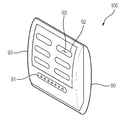
도 3내지 도 4는 일반적인 포충등의 사시도로서, 도 3은 포충등의 도어부가 닫힌 상태를 도시한 사시도이고, 도 4는 도 3에 도시된 포충등의 도어부가 열린 상태를 도시한 사시도이다.3 to 4 are perspective views of a general insect repellent lamp, FIG. 3 is a perspective view showing a state in which the door part of the insect repellent lamp is closed, and FIG. 4 is a perspective view showing a state in which the door part of the insect repellent lamp shown in FIG. 3 is opened.
이에 도시된 바와 같이, 상기 포충등(100)은 본체부(80) 및 도어부(90)를 포함하고, 상기 본체부(80)는 유인등(83), 끈끈이(82), 포충등 제어유닛(140), 제 1송신유닛(120), 제 2수신유닛(130), 통신모듈(86), 유인제 수용부(84) 및 스피커(85)를 포함한다.As shown therein, the
상기 유인등(83)은 복수 개 구비되는 것이 일반적이며, 자외선과 같은 빛을 발산시켜 비래해충을 유인할 수 있도록 구비된다. 상기 끈끈이(82)는 일면에 상기 비래해충을 포획할 수 있도록, 접착제가 도포되는 것이 일반적이며, 상기 끈 끈이(82) 대신 해충수납용기가 구비되어, 상기 유인등(83)으로 유인되어 하부방향으로 낙하하는 상기 비래해충의 사체를 수납하도록 구비될 수 있다.It is generally provided with a plurality of attracting
상기 포충등 제어유닛(140), 상기 제 1송신유닛(120) 및 상기 제 2수신유닛(130)에 관한 것은 차후에 후술하기로 한다.The insect
상기 통신모듈(86) 및 상기 스피커(85)는 상기 포충등 제어유닛(140)에 의해 제어되며, 상기 통신모듈(86)은 상기 포충등 제어유닛(140)에서 지시하는 내용을 사용자에게 통신으로 단문메시지를 발신할 수 있도록 구비되고, 상기 스피커(85)는 상기 포충등 제어유닛(140)에서 지시하는 내용에 의해 경고음 또는 음성신호 중 적어도 하나를 생성하도록 구비된다.The
상기 유인제 수용부(84)는 상기 포충등(100)으로 상기 비래해충을 유인할 수 있는 유인제를 수용하도록 구비된다. 본 실시예에서는 상기 유인제 수용부(84)가 제시되었지만, 이에 한정되거나 제한되는 것은 아니며, 예를 들면, 상기 유인제 수용부(84)는 생략되거나, 상기 포충등(100)으로 유인된 상기 비래해충을 살충할 수 있는 살충제 수용부로 대체되는 것도 가능하다.The
상기 도어부(90)는 표시부(91), 개방부(92) 및 해충진입부(93)를 포함하고, 상기 본체부(80)에 개폐가 가능하도록 힌지결합된다.The
상기 표시부(91)는 복수개의 제어 가능한 발광 다이오드(LED)를 배치하여 구비되며, 상기 표시부(91)는 상기 포충등 제어유닛(140)의 제어에 의해 점멸, 점등 및 소등의 형태로 제어되도록 구비된다. 본 실시예에서는 상기 표시부(91)가 발광다이오드를 배치하여 구성되는 것으로 제시되었지만 이에 한정되거나 제한되는 것은 아니며, 예를 들면, 문자나 이미지를 표시할 수 있는 액정디스플레이(LCD)로 구비되는 것도 가능하다.The
상기 개방부(92)는 상기 포충등 제어유닛(140)에 의해 개폐의 제어가 가능하도록 복수 개가 구비된다. 상기 개방부(92)의 제어는 상하 제어가 가능한 피스톤(미도시) 또는 모터(미도시)에 의해 상기 개방부(92)가 상하이동 또는 회동을 통해 개폐될 수 있도록 구비된다.The opening
여기서, 상기 해충진입부(93)는 다수개의 홀 형태로 상기 도어부(90)를 관통하여 형성되며, 상기 개방부(92)가 열림 동작을 하고 있는 경우에 상기 비래해충이 상기 포충등의 내부로 진입할 수 있도록 구비된다.Here, the
도 5는 본 발명의 제 1실시예에 따른 포충등의 인터렉티브 시스템의 구성을 도시한 것이다.Fig. 5 shows the configuration of an interactive system such as a insect repellent lamp according to the first embodiment of the present invention.
이에 도시된 바와 같이, 포충등의 인터렉티브 시스템에는 센서(110), 제 1송신유닛(120), 제 1수신유닛(310), 관제유닛(330), 제 2송신유닛(350), 제 2수신유닛(130), 포충등 제어유닛(140) 및 상기 포충등(100)과 상기 관제센터(300)의 정보를 송수신하게 하는 통신망(200)이 포함되고, 상기 센서(110), 제 1송신유닛(120), 제 2수신유닛(130) 및 포충등 제어유닛(140)은 포충등(100)에 구비되며, 상기 제 1수신유닛(310), 관제유닛(330), 제 2송신유닛(350)은 상기 포충등(110)과 원격으로 떨어진 별도의 관제센터(300)에 구비된다.As shown in the drawing, the interactive system such as the
상기 센서(110)는 상기 포충등(100)의 내부, 외부 및 인접한 곳에 배치되어 구비되며, 상기 센서(110)는 각 특성에 따라 상기 포충등(100) 및 상기 포충 등(100)이 설치된 곳의 정보를 수집하고, 상기 정보를 제 1정보라 한다. 상기 제 1정보에 관한 설명은 도 9내지 도 32를 참조하여 후술하기로 한다.The
상기 센서(110)는 자외선 강도 또는 조도를 감지하는 광센서, 압력센서, 서미스터, 열전대, 마이메탈과 같은 온도센서, 풍압센서, 습도센서, 정전용량센서, 고주파 발진형센서, 홀 센서 및 전기저항센서와 같은 근접센서, 적외선 에어리어 센서, 가속도 센서 및 전류 변화 감지 센서 중 적어도 하나를 포함하고, 필요에 따라 조합하여 사용될 수 있으며 이에 한정되거나 제한되는 것은 아니다.The
또한, 상기 광센서 중 자외선 강도를 측정하는 광센서는 일반적으로 고가의 장비이므로, 일반 광센서로 조도를 측정하고 이를 기 설정된 조도 기준에 따라 자외선 강도로 계산하여 사용하는 것도 가능하다.In addition, since the optical sensor for measuring the intensity of the ultraviolet light of the optical sensor is generally expensive equipment, it is also possible to measure the illumination with a general optical sensor and use it by calculating the ultraviolet intensity according to a predetermined illuminance criteria.
상기 제 1송신유닛(120)은 상기 센서(110)에서 수집된 상기 제 1정보를 원격지에 위치된 상기 관제센터(300)로 송신하는 역할을 하기 위해 일반적으로 상용되고 있는 송신기(transmitter)를 사용하며, 상기 송신기는 일반적으로 신호, 즉 음성, 음악, 화상(畵像) 또는 전신부호, 데이터 등을 전기신호로 바꿔 전력을 증폭시켜 공중의 무선전파나 전기 케이블에 전류의 형태로 내보내는 장치를 말하며, 본 실시예에서는 상기 통신망(200)을 통해서 송신하는 장치를 말한다.The
송신된 상기 제 1정보는 상기 관제센터(300)에 구비된 상기 제 1수신유닛(310)에 의해 수신되고, 상기 수신된 제 1정보에 따라 상기 관제유닛은 제 2정보를 생산하는 역할을 한다. 상기 제 1수신유닛(310)으로는 일반적으로 상용되고 있는 수신기가 사용 될 수 있으며, 이에 한정되거나 제한되는 것은 아니며, 예를 들 면, 상기 제 1송신유닛으로 사용되는 송신기의 신호를 수신하는 장치이면 어떤 형태이든 가능하다.The transmitted first information is received by the
또한, 상기 관제유닛(330)은 공지의 마이크로프로세서가 사용되며, 상기 제 2송신유닛(350)은 상기 제 2정보를 상기 포충등으로 송신하는 역할을 하고, 상기 제 2수신유닛(130)은 상기 송신된 제 2정보를 수신하는 역할을 한다. 또한, 상기 포충등 제어유닛(140)은 상기 제 2신호에 따라 상기 포충등(100)을 제어할 수 있는 제어신호를 발생시키는 역할을 한다.In addition, the
상기 포충등 제어유닛(140)은 일반적으로 상용되는 마이크로프로세서를 사용할 수 있으며, 상기 포충등 제어유닛(140)에서 생산되는 제어신호는 도 9내지 도 32를 참조하여 후술하기로 한다.The insect
상기 통신망(200)은 근거리 통신망(LAN), 광대역 통신망(WAN), 공중 전화망(PSTN), 패킷 교환망(PSDN), 비대칭 디지털 가입자선(ADSL), 종합 통신망(ISDN), 코드분할다중접속(CDMA) 및 이더넷(ETHERNET) 중 적어도 하나 이상을 포함하여 구성되며, 일반적으로는 코드분할 다중접속과 이더넷을 복합적으로 구성하지만, 이에 한정되거나 제한되는 것은 아니며, 예를 들면, 상기 통신망(200)을 세 개 이상의 통신망 종류를 조합하여 구성하는 것도 가능하다.The
본 발명의 제 1실시예에 따른 포충등의 인터렉티브 시스템의 운용방법을 도 5 및 도 6을 참조하여 설명하면 다음과 같다. 도 6은 포충등의 인터렉티브 시스템의 운용방법을 도시한 순서도이다.A method of operating an interactive system such as an insect insect according to the first embodiment of the present invention will be described with reference to FIGS. 5 and 6. 6 is a flowchart illustrating a method of operating an interactive system such as insects.
이에 도시된 바와 같이, 먼저 상기 포충등에 구비된 센서(110)에서 감지된 제 1정보를 수집한다(S01).As shown in FIG. 1, first, the first information detected by the
다음, 상기 포충등(100)에 구비된 상기 제 1송신유닛(120)에 의해 상기 제 1정보를 원격지에 별도로 위치된 관제센터(300)로 송신한다(S02).Next, the first information is transmitted to the
다음, 상기 관제센터(300)에 구비된 상기 제 1수신유닛(310)에서 상기 제 1정보를 수신하고(S03), 상기 관제유닛(330)에서 수신된 상기 제 1정보에 따라 제 2정보를 생성한다(S04).Next, the
다음, 상기 제 2정보를 상기 제 2송신유닛(350)에 의해 다시 상기 포충등(100)으로 송신한다(S05).Next, the second information is transmitted back to the
다음, 상기 포충등(100)에 구비된 상기 제 2수신유닛(130)에서 상기 제 2정보를 수신하고(S06), 상기 포충등 제어유닛(140)에서 상기 제 2정보에 따라 제어신호를 생성한다(S07).Next, the
다음, 상기 생성된 제어신호에 따라 상기 포충등(100)을 제어(S08)함으로써, 포충등의 인터렉티브 시스템을 운용한다.Next, by controlling the
제 My 2실시예2 Example
도 7은 본 발명의 제 2실시예에 따른 포충등의 인터렉티브 시스템을 도시한 것이다. 참고로, 설명의 편의를 위하여 도 5에 도시된 본 발명의 제 1실시예와 동일한 구성에 대해서는 동일한 참조번호를 참조하며, 이에 따라 별도로 설명하지 않기로 하고, 필요에 따라 설명하기로 한다.7 illustrates an interactive system such as a insect repellent lamp according to a second embodiment of the present invention. For reference, for the convenience of description, the same reference numerals refer to the same elements as in the first embodiment of the present invention shown in FIG. 5, and thus will not be described separately, and will be described as necessary.
이에 도시된 바와 같이, 포충등의 인터렉티브 시스템은 센서(110), 포충등 제어유닛(140)을 포함하는 마이크로프로세서(145), 제 1송신유닛(120), 메모리유닛(170), 제 2수신유닛(130), 입력유닛(190), 제어기(150)를 구비하는 포충등(100), 상기 포충등(100)과 원격으로 떨어져 별도로 위치되어 제 1수신유닛(310), 해석유닛(335)을 포함하는 관제유닛(330), 제 2송신유닛(350), 서버유닛(320)을 구비하는 관제센터(300) 및 통신망(200)을 포함한다.As shown therein, the interactive system of the insect lamp includes a
상기 포충등(100)에 구비된 상기 입력유닛(190)은 방제를 수행하는 방제 직원이 상기 포충등(100)을 점검하는 과정에서 상기 포충등(100)의 점검여부, 점검일, 점검자 및 점검내용을 포함하는 점검정보를 입력할 수 있도록 구비되며, 일반적으로 키패드의 형태로 구비되지만, 이에 한정되거나 제한되는 것은 아니며, 예를 들면, 전파식별(RFID, radio frequency identification)을 통한 비접촉식 형태나 범용직렬버스(USB)의 형태로 상기 점검 정보를 입력할 수 있도록 구비되는 것도 가능하다.The
또한, 상기 포충등의 인터렉티브 시스템은 상기 포충등(100)이 복수개가 배치되어 구성될 수 있으며, 상기 경우에는 상기 포충등(100)의 점검여부, 점검일, 점검자, 점검내용 및 셋팅 정보를 입력하는 집중기(미도시)를 더 포함할 수 있다. 이에 따라, 상기 입력유닛(190)을 대체하여 상기 집중기에서 상기 점검 정보 및 셋팅 정보를 입력할 수 있도록 구성되는 것도 가능하다. 그리고, 상기 집중기에서 입력된 점검 정보 및 셋팅정보는 상술한 바와 유사하게 상기 메모리유닛(170)에 저장된다.In addition, the interactive system of the insect repellent lamp may be composed of a plurality of the
상기 집중기는 상기 포충등(100)이 복수개 배치되는 경우에 구비되는 것이 일반적이며, 상기 포충등(100)과 상기 관제센터(300)간에 송수신되는 정보가 경유하도록 구비된다. 여기서, 복수개의 상기 포충등(100) 중 일부에서 모인 정보를 상기 집중기에서 수집하여 상기 관제센터(300)로 송신하게 되고, 상기 정보를 상기 집중기에 저장하도록 구비된다.The concentrator is generally provided when a plurality of
따라서, 상기 포충등(100)을 관리하는 상기 방제직원이 상기 포충등(100)을 일일이 방문하지 않고, 상기 집중기에서 필요한 정보를 다운로드 받거나 또는 수신 받아 필요한 상기 포충등(100)에만 방문하면 되므로, 상대적으로 저렴한 비용이 소요되고, 효율적인 방제작업을 진행하는 것이 가능한 효과가 있다.Therefore, the control staff who manages the
상기 메모리유닛(170)은 상기 센서(110)에서 수집된 정보 및 상기 입력유닛(190)에 의해 입력된 점검정보를 저장하는 역할을 하며, 또한, 상기 포충등(100)의 셋팅정보를 저장할 수 있도록 구비된다. 그리고, 상기 메모리유닛(170)에 저장된 정보를 상기 범용직렬버스를 통해 외부에서 다운로드 할 수 있도록 구비되며, 상기 점검정보는 상기 제 1정보에 포함된다.The
상기 제어기(150)는 상기 포충등 제어유닛(140)에서 생산되는 제어신호에 따라 상기 포충등(100)을 제어하는 역할을 하며, 상기 제어기(150)는 모터, 발광다이오드(LED), 개방부, 등(Lamp), 통신모듈 및 상기 메모리유닛(170) 등과 같은 상기 포충등(100)에 구비되는 기기들을 제어할 수 있도록 구비되며, 이에 대한 상세한 설명은 상기 제 1정보 및 상기 제 2정보와 함께 도 9내지 도 32를 참조하여 후술하기로 한다.The
상기 관제센터(300)에 구비된 상기 해석유닛(335)은 상기 제 1수신유 닛(310)에 의해 수신된 상기 제 1정보를 해석하고 가공하여 상기 관제유닛(330)에서 상기 제 2정보를 생성하는 것을 보조하는 역할을 하며, 일반적으로 상용되는 마이크로프로세서를 사용한다.The
또한 상기 관제유닛(330)은 상기 제 1정보에 대하여 독립적인 제 3정보를 생산하며, 상기 제 3정보는 상기 제 2송신유닛(350)에 의해 상기 제 2수신유닛(130)으로 송수신된다.In addition, the
상기 제 3정보는 상기 메모리 유닛의 기 저장된 셋팅 값을 변화시키는 정보, 음성정보 또는 영상정보 중 적어도 하나 이상으로 구성된다.The third information includes at least one of information, audio information, or video information for changing a pre-stored setting value of the memory unit.
그리고, 상기 제 3정보는 음성 또는 영상정보인 경우에는 상기 포충등(100)은 상기 영상정보를 게시하도록 디스플레이 유닛(미도시)를 구비하는 것도 가능하다. 여기서, 상기 영상정보는 광고 또는 안내정보 중 적어도 하나이며, 상기 안내정보는 일반해충정보, 위생정보, 정기점검 알림 정보 및 태풍, 호우, 건조 및 돌풍 경보, 주의보와 같은 기후정보를 포함한다.In addition, when the third information is audio or video information, the
여기서, 상기 디스플레이유닛(미도시)는 액정디스플레이(LCD), 발광다이오드(LED) 또는 유기이엘(OELD, Organic Electro Luminescence Display) 중 적어도 하나 이상을 포함하여 구성되는 것이 바람직하며 이에 한정되거나 제한되는 것은 아니며, 브라운관(CRT)를 포함하여 구성되는 것도 가능하다.Here, the display unit (not shown) is preferably configured to include at least one or more of a liquid crystal display (LCD), a light emitting diode (LED) or an organic EL (OELD, Organic Electro Luminescence Display) is limited or limited thereto It is also possible to comprise a cathode ray tube (CRT).
본 실시예에서는 상기 제 3정보를 상기 통신망(200)을 통해 송수신하는 방법을 제시하였지만, 이에 한정되거나 제한되는 것은 아니며, 예를 들면, 상기 제 3정보를 상기 관제유닛(330)으로부터 다운로드 한 후 방제를 수행하는 사람이 상기 포충등(100)에 입력하는 방법을 통해, 상기 음성 및 영상정보는 상기 포충등(100)에 구비된 디스플레이유닛(미도시)과 스피커(85)에 의해 게시되고, 상기 포충등(100)에 기 저장된 셋팅 값을 변화시키는 정보는 상기 포충등(100)의 기 저장된 셋팅 값을 변화시키는 것도 가능하다. In the present embodiment, a method of transmitting and receiving the third information through the
상기 서버유닛(320)은 상기 제 1수신유닛(310)에 의해 수신된 상기 제 1정보 및 상기 관제유닛(330)에서 생산되는 상기 제 2정보를 저장하는 역할을 하며, 일반적으로 상용되고 있는 마이크로프로세서가 접근할 수 있도록 데이터를 전자기 형태로 저장하는 스토리지(storage)가 사용된다.The
본 발명의 제 2실시예에 따른 포충등의 인터렉티브 시스템의 운용방법을 도 7 및 도 8을 참조하여 설명하면 다음과 같다. 도 8은 본 발명의 제 2실시예에 따른 포충등의 인터렉티브 시스템의 운용방법을 도시한 순서도이다.A method of operating an interactive system such as an insect insect according to a second embodiment of the present invention will be described with reference to FIGS. 7 and 8 as follows. 8 is a flowchart illustrating a method of operating an interactive system such as an insect insect, according to a second embodiment of the present invention.
이에 도시된 바와 같이, 먼저 상기 포충등에 구비된 센서(110)에서 감지된 제 1정보를 감지하는 센싱 단계(S11)를 거친다. 이 과정에서, 상기 포충등 제어유닛(140)을 포함하는 상기 마이크로 프로세서를 경유할 수 있으며, 이에 따라 상기 제 1정보는 상기 제 1송신유닛(120)에서 송신하기가 용이한 형태로 가공 및 변형되는 것이 가능하다.As shown in the figure, first, the sensing step (S11) for detecting the first information detected by the
또한, 상기 센싱단계(S11)에서 상기 제 1정보는 상기 입력유닛(190)에서 입력된 점검정보를 더 포함한다.In addition, in the sensing step S11, the first information further includes check information input from the
다음, 상기 제 1정보를 상기 메모리 유닛에 저장하는 제 1저장단계를 거친다(S12).Next, a first storage step of storing the first information in the memory unit is performed (S12).
다음, 상기 포충등(100)에 구비된 상기 제 1송신유닛(120)에 의해 상기 제 1정보를 원격지에 별도로 위치된 관제센터(300)로 송신한다(S13).Next, the first information is transmitted to the
다음, 상기 관제센터(300)에 구비된 상기 제 1수신유닛(310)에서 상기 제 1정보를 수신하고, 상기 제 1정보를 상기 서버유닛(320)에 저장한다(S14).Next, the
다음, 상기 관제유닛(330)에서 수신된 상기 제 1정보에 따라 제 2정보를 생성하는 제 1생성단계(S15)를 거친다. 여기서, 상기 제 1정보를 상기 관제유닛(330)에 구비된 상기 해석유닛(335)에 의해 해석 및 가공하여 상기 제 2정보를 생성하도록 보조한다(S151).Next, a first generation step S15 of generating second information according to the first information received from the
다음, 상기 제 2정보를 상기 서버유닛(320)에 저장한다(S16).Next, the second information is stored in the server unit 320 (S16).
다음, 상기 제 2정보를 상기 제 2송신유닛(350)에 의해 다시 상기 포충등(100)으로 송신한다(S17).Next, the second information is transmitted to the
다음, 상기 포충등(100)에 구비된 상기 제 2수신유닛(130)에서 상기 제 2정보를 수신한다(S18).Next, the second information is received by the
다음, 상기 포충등 제어유닛(140)에서 상기 제 2정보에 따라 제어신호를 생성한다(S19).Next, the insect
다음, 상기 생성된 제어신호에 따라 상기 제어기(150)에 의해 상기 포충등(100)을 제어함(S20)으로써, 포충등의 인터렉티브 시스템을 운용한다.Next, by controlling the
또한, 상기 센싱 단계(S11)에서 상기 센서가 카메라(미도시)이고, 상기 카메라를 통해 비전정보를 수집하고, 상기 비전정보를 해석하여 비전해석정보를 생산하는 해석모듈(미도시)을 포함하는 것도 가능하며 상기 제 1정보가 상기 비전정보 및 상기 비전해석정보를 더 포함하는 것도 가능하다.In addition, the sensor in the sensing step (S11) is a camera (not shown), and collects vision information through the camera, and includes an analysis module (not shown) for producing the vision analysis information by analyzing the vision information. In addition, the first information may further include the vision information and the vision interpretation information.
여기서, 상기 카메라는 일반적으로 상기 포충등(100)에 구비된 상기 끈끈이(82)를 촬영함으로써 센싱하고, 이에 따라, 상기 비전해석정보는 포획되는 해충의 개체수를 파악한 포획량 정보 및 포획면적정보를 포함하나, 이에 한정되거나 제한되는 것은 아니며, 상기 끈끈이(83)에 포획되는 해충의 종류를 파악하는 것도 가능하다.Here, the camera is generally sensed by photographing the sticky 82 provided in the
상기 제 1생성단계(S15)에서, 상기 관제유닛(330)은 상기 제 1정보에 대하여 독립적인 제 3정보를 생산하는 제 2생성단계(미도시)를 더 포함할 수 있다. 이에 따라, 상기 제 2정보를 송수신하는 방법과 유사하게 상기 제 2송신유닛(350)은 상기 제 3정보를 상기 포충등(100)으로 송신하고, 상기 제 2수신유닛(130)은 상기 제 3정보를 수신하여 상기 포충등(100)에 구비된 메모리 유닛(170)에 기 저장된 셋팅 값을 변화시키고, 상기 음성 및 영상정보는 상기 포충등(100)에 구비된 상기 스피커(85)와 상기 디스플레이유닛(미도시)에 게시한다.In the first generation step (S15), the
또한, 상기 포충등의 인터렉티브 시스템의 운용방법에서 상기 단계들은 일회성으로 운용되는 것이 아니라, 일반적으로 상기 포충등(100)이 작동되는 동안 상시 운영되거나 또는 일정한 주기를 가지고 운용되나, 이에 한정되거나 제한되는 것은 아니며, 예를 들면, 상기 제어신호에 의해 상기 포충등(100)이 제어된 결과를 상기 관제센터(300)로 재 송신하는 것도 가능하다.In addition, in the method of operating the interactive system such as the insect repellent, the steps are not operated one-time, but are usually operated at regular intervals or at regular intervals while the
본 발명의 실시예에 따른 상기 제 1정보, 상기 제 1정보에 대응되는 상기 제 2정보 및 상기 제 2정보에 따른 제어신호에 대해 설명하면 다음과 같다. 설명의 편의를 위하여 상기 제 1정보, 상기 제 2정보 및 제어신호를 표1로 먼저 설명하고 난 후 각각에 대해 상세히 설명하기로 한다.The first information, the second information corresponding to the first information, and the control signal according to the second information according to an embodiment of the present invention will be described below. For convenience of explanation, the first information, the second information, and the control signal will be described first with Table 1, and then each will be described in detail.
상기 제 1정보 및 상기 제2정보를 각각 나타낸 표1은 다음과 같다.Table 1 showing the first information and the second information is as follows.


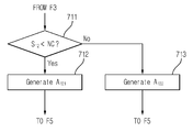
여기서 표 1은 상기 제 1정보(Si)에 대응되는 상기 제 2정보(Aij)와 이에 따른 제어신호(Cijk)를 각각 대응되도록 표시한 것이다. 표 1에 서술된 바와 같이, 각 제 2정보(Aij)에 따라, 복수 개의 제어신호(Cijk)를 생성할 수도 있으며, 이에 한정되거나 제한되는 것은 아니며, 상기 제어신호(Cijk)는 포충등에 구비된 장비에 따라 등가로 변경되거나 치환될 수 있다.Here, Table 1 shows a display corresponding to each of the second information (A ij) and its control signal (C ijk) according to corresponding to the first information (S i). As described in Table 1, for each second information (A ij), and also generates a plurality of control signals (C ijk), is not limited or restricted to, the control signal (C ijk) is pochung It may be changed or replaced equivalently depending on the equipment provided in the back.
상기 센서(110)에서 수집된 상기 제 1정보(Si)와 상기 제 1정보(Si)에 따른 상기 제 2정보(Aij) 및 상기 제 2정보(Aij)에 따른 상기 제어신호(Cijk)를 함수로 표현하면 수학식 1과 같다.Said control signal corresponding to the first information (S i) with the first information (S i) and the second information (A ij) and the second information (A ij) in accordance with the gathered from the sensor 110 ( C ijk ) is expressed as a function of Equation 1.
![]()
![]()
여기서, 상기 제 2정보(Aij)는 후술하는 제 1정보(Si)의 흐름 및 처리 절차에 의해 상기 제 1정보(Si)에 의해 결정되는 함수로 표현할 수 있으며, 상기 제어신호(Cijk) 또한 상기 제 2정보(Aij)에 의해 결정되는 상기 제 2정보(Aij)의 함수로 표현되는 것이 가능하다.Here, the second information (A ij) may be represented as a function that is determined by by the flow and processing of the first information (S i) to be described later to the first information (S i), said control signal (C ijk) also it can be expressed as a function of the second information (a ij), which is determined by the second information (a ij).
이하에서 표 1에서 서술된 각각의 상기 제 1정보, 상기 제 2정보 및 상기 제어신호의 관계를 설명하면 다음과 같다. 이하, 설명된 제1 정보 및 제2 정보의 흐름 및 처리절차는 제1 및 제 2실시예에 공통되게 적용될 수 있다.Hereinafter, the relationship between each of the first information, the second information, and the control signal described in Table 1 will be described. Hereinafter, the flow and processing procedures of the first information and the second information described may be commonly applied to the first and second embodiments.
먼저, 도 9는 본 발명의 실시예에 따른 제 1정보와 제 2정보 및 제어신호의 흐름과 생성을 일반적으로 나타낸 순서도이다.First, FIG. 9 is a flow chart generally showing flow and generation of first information, second information, and a control signal according to an embodiment of the present invention.
이에 도시된 바와 같이, 먼저 제 1정보(Si)를 수집하고(F1), 다음으로 상기 제 1정보(Si)를 송신한다(F2).Thus As shown, it transmits first the first information (S i) collected and (F1), the first information (S i) to the next (F2).
다음, 상기 제 1정보(Si)를 수신한다(F3).And then, it receives the first information (S i) (F3).
다음, 상기 제 1정보(Si)에 따라 제 2정보(Aij)를 생산한다(F4).Next, according to the first information (S i ) to produce a second information (A ij ) (F4).
다음, 상기 제 2정보(Aij)를 송신하고(F5), 수신한다(F6).Next, the second information A ij is transmitted (F5) and received (F6).
다음, 수신된 상기 제 2정보(Aij)에 따라 제어신호(Cijk)를 생성하고(F7), 상기 제어신호(Cijk)에 따라, 포충등을 제어한다(F8).Next, a control signal C ijk is generated according to the received second information A ij (F7), and an insect trap is controlled according to the control signal C ijk (F8).
참고로, 점선으로 도시한 바와 같이 상기 F1, F2, F6, F7 및 F8단계는 상기 포충등(100)에서 실행되고, 상기 F3 내지 F5단계는 상기 관제센터(300)에서 실행된다.For reference, the F1, F2, F6, F7 and F8 steps are performed in the
여기서, 상기 제 1정보(Si)에 따라 상기 제 2정보(Aij)를 생산하는 단계(F4)를 표 1에 도시된 각각의 경우에 따라 설명하면 다음과 같다.Here, the step (F4) of producing the second information (A ij ) according to the first information (S i ) will be described according to each case shown in Table 1 as follows.
도 10은 상기 제 1정보(Si)가 등 밝기 정보(S1)인 경우에 상기 제 2정보(Aij)를 생성하는 도 9에 도시된 F4단계를 설명한 순서도이다.10 is a flowchart illustrating the steps of F4 shown in Figure 9 to generate the second information (A ij) in the case of the first information (S i) the brightness information (S 1).
이에 도시된 바와 같이, 먼저, 상기 등 밝기 정보(S1)를 기 설정된 등 밝기 기준 범위(LL~LH)에 포함되는지 비교한다(601).As shown in FIG. 1, first, the lamp brightness information S 1 is compared with the preset lamp brightness reference range L L to L H (601).
이 과정에서 상기 등 밝기 정보(S1)가 상기 등 밝기 기준 범위(LL~LH)에 포함되면, 이에 따라 정상 정보로 제 2정보(A11)를 생성하고(602), 포함되지 않으면, 등 밝기 최저기준(L0)과 비교한다(603).In this process, if the lamp brightness information S 1 is included in the lamp brightness reference range L L to L H , accordingly, the second information A 11 is generated as normal information (602). , And is compared with the lowest brightness reference (L 0 ) (603).
상기 603단계에서 상기 등 밝기 정보(S1)가 상기 등 밝기 최저기준(L0)보다 작으면, 이에 따라 등 교환신호로 제 2정보(A12)를 생성하고(604), 작지 않으면 상기 등 밝기 기준 범위(LL~LH)의 높은 기준(LH)보다 더 큰가의 여부를 비교한다(605).If the lamp brightness information S 1 is smaller than the lamp brightness minimum standard L 0 in
상기 605단계에서 상기 등 밝기 정보(S1)가 상기 등 밝기 높은 기준 (LH)보다 더 큰 경우에는 등 밝기감소 변경신호로 제 2정보(A13)를 생성하고(606), 크지 않은 경우에는 등 밝기증가 변경신호로 제 2정보(A14)를 생성한다(607).If the lamp brightness information S 1 is greater than the lamp high reference L H in
이에 따라, 상기 제 2정보(A1j)에 대응하는 제어신호(C1jk)를 빛 또는 소리로 등 교환신호(C111), 등 밝기를 감소시키거나 또는 증가시키는 전류변경신호(C121, C121) 및 전압변경신호(C123, C124)로 생성한다.Accordingly, the control signal C 1jk corresponding to the second information A 1j to the light or sound exchange signal C 111 , the current change signal C 121 , C to decrease or increase the brightness of the lamp. 121 ) and the voltage change signals C 123 and C 124 .
상기 등 밝기 정보(S1)는 일반적으로 조도를 사용하며, 이에 한정되거나 제한되는 것은 아니며, 자외선 강도를 사용할 수도 있으며, 상기 조도를 감지하여 기 설정된 조도 기준에 의거하여 상기 자외선 강도를 계산하여 사용하는 것도 가능하다.The brightness information S 1 generally uses illuminance, and is not limited or limited thereto. An ultraviolet intensity may be used, and the ultraviolet intensity is detected and calculated based on a predetermined illuminance standard. It is also possible.
도 11은 상기 제 1정보(Si)가 포충등 내, 외부 온도정보(S2)인 경우에 상기 제 2정보(Aij)를 생성하는 도 9에 도시된 F4단계를 설명한 순서도이다.11 is a flowchart illustrating the steps of F4 shown in Figure 9 to generate the second information (A ij) in the case of the first information (S i) is pochung including internal and external temperature information (S 2).
이에 도시된 바와 같이, 상기 포충등 내, 외부 온도정보(S2)를 기 설정된 제 1온도(T1)와 비교한다(611).As shown therein, the internal temperature information S 2 in the insect lamp is compared with the preset first temperature T 1 (611).
이 과정에서, 상기 온도정보(S2)가 상기 제 1온도(T1)보다 크거나 같은 경우에는 화재경보(A21)를 생성하고(612), 작은 경우에는 기 설정된 제 2온도(T2)와 비교한다(613).In this process, when the temperature information S 2 is greater than or equal to the first temperature T 1 , a fire alarm A 21 is generated (612), and when the temperature information S 2 is smaller than the preset second temperature (T 2) (613).
상기 613단계에서 상기 온도정보(S2)가 상기 제 2온도(T2) 이상인 경우에는 과열경보(A22)를 생성하고(614), 작은 경우에는 기 설정된 제 3온도(T3)와 비교한다(615).When the temperature information S 2 is greater than or equal to the second temperature T 2 , in
상기 615단계에서 상기 온도정보(S2)가 상기 제 3온도(T3)보다 작은 경우에는 저온경보(A23)를 생성하고(616), 크거나 같은 경우에는 정상정보(A24)를 생성한다(617).In
이에 따라, 제어신호(C2jk)는 상기 제 2정보(A2j)에 따라 j가 1인 경우에는 강제전원차단신호(C211), 소방서에 연락신호(C212), 빛 또는 소리로 화재경보 발생신호(C213) 및 사용자에게 통신으로 단문 메시지 발송(C214) 중 적어도 하나 이상의 신호를 생성하고, j가 2인 경우에는 냉각작업시행신호(C221), 빛 또는 소리로 과열경 보표시 신호(C222) 또는 강제 전원차단신호(C223) 중 적어도 하나 이상의 신호를 생성하며, j가 3인 경우에는 빛 또는 소리로 저온경보발생신호(C231), 강제 전원 차단 신호(C232) 및 해충 활동 없음 표시(C233) 중 적어도 하나 이상의 신호를 생성하고, 그리고, j가 4인 경우에는 정상 표시(C241) 신호를 생성한다.Accordingly, the control signal C 2jk is a forced power cutoff signal C 211 when the j is 1 according to the second information A 2j , a contact signal C 212 to the fire station, a fire alarm with light or sound. At least one signal generated from the generated signal (C 213 ) and the communication to the user by sending a short message (C 214 ), when j is 2, the cooling operation execution signal (C 221 ), the overheat alarm display with light or sound Generate at least one signal of the signal (C 222 ) or the forced power off signal (C 223 ), when j is 3, the low temperature alarm generation signal (C 231 ), the forced power off signal (C 232 ) by light or sound And at least one signal of no pest activity indication (C 233 ), and generates a normal indication (C 241 ) signal when j is 4.
본 실시예에서는 상기 화재경보(A21)을 상기 제 1정보가 온도정보(S2)일 때로 제시하였지만, 이에 한정되거나 제한되는 것은 아니며 연기를 감지하는 센서를 구비하여, 이에 따라 일정 연기량 이상이면 상기 화재경보(A21)를 생성하는 것도 가능하다.In the present embodiment, the fire alarm A 21 is presented when the first information is the temperature information S 2. However, the fire alarm A 21 is not limited or limited thereto, and is provided with a sensor for detecting smoke. It is also possible to generate the fire alarm A 21 .
도 12는 상기 제 1정보(Si)가 풍속 정보(S3)인 경우에 상기 제 2정보(Aij)를 생성하는 도 9에 도시된 F4단계를 설명한 순서도이다.12 is a flowchart illustrating the steps of F4 shown in Figure 9 to generate the second information (A ij) in the case of the first information (S i) a wind speed information (S 3).
이에 도시된 바와 같이, 먼저, 상기 풍속정보(S3)를 기 설정된 풍속 기준(W)과 비교한다(621). 상기 단계(621)에서 상기 풍속정보(S3)가 상기 풍속 기준(W)보다 큰 경우에는 강풍 경보(A31)를 생성하고(622), 작거나 같은 경우에는 정상 정보(A32)를 생성한다(623).As shown in FIG. 1, first, the wind speed information S 3 is compared with a preset wind speed reference W (621). In
이에 따라, 상기 제어신호(C3jk)는 상기 제 2정보(A3j)에 따라, j가 1인 경우에는 빛 또는 소리로 강풍경보표시 신호(C311) 및 강제 전원차단 신호(C312) 중 적 어도 하나를 생성하고, j가 2인 경우에는 정상 표시 신호(C321)를 생성한다.Accordingly, the control signal (C 3jk ) of the strong wind alarm display signal (C 311 ) and the forced power off signal (C 312 ) by light or sound when j is 1 according to the second information (A 3j ). Generate at least one, and generate j normal display signal (C 321 ) when j is 2.
도 13은 상기 제 1정보(Si)가 강우량정보(S4)인 경우에 상기 제 2정보(Aij)를 생성하는 도 9에 도시된 F4단계를 설명한 순서도이다.13 is a flowchart illustrating the steps of F4 shown in Figure 9 to generate the second information (A ij) in the case of the first information (S i) the rainfall information (S 4).
이에 도시된 바와 같이, 먼저, 상기 강우량정보(S4)를 기 설정된 강우량 기준(R)과 비교한다(631). 상기 단계(631)에서 상기 강우량정보(S4)가 상기 강우 기준(R)보다 큰 경우에는 강우 경보(A41)를 생성하고(632), 작거나 같은 경우에는 정상 정보(A42)를 생성한다(633).As shown in the figure, first, the rainfall information S 4 is compared with a preset rainfall criterion R (631). In
이에 따라, 상기 제어신호(C4jk)는 상기 제 2정보(A4j)에 따라, j가 1인 경우에는 누전 가능경보발생 신호(C411), 호우 경보발생 신호(C412), 개방부 폐쇄 신호(C413) 및 강제 전원차단신호(C414) 중 적어도 하나를 생성하고, j가 2인 경우에는 정상 표시 신호(C421)를 생성한다.Accordingly, the control signal (C 4jk ) according to the second information (A 4j ), when j is 1, the earth leakage possible alarm generation signal (C 411 ), heavy rain alarm generation signal (C 412 ), opening closed At least one of the signal C 413 and the forced power off signal C 414 is generated, and when j is 2, the normal display signal C 421 is generated.
도 14는 상기 제 1정보(Si)가 도어부 개폐 정보(S5)인 경우에 상기 제 2정보(Aij)를 생성하는 도 9에 도시된 F4단계를 설명한 순서도이다. 참고로 상기 도어부 개폐 정보(S5)는 상기 포충등이 작동하고 있는 상황에서 수집된 정보이다.14 is a flow chart for explaining a step of F4 shown in Figure 9 to generate the second information (A ij) in the case of the first information (S i) of the door opening and closing unit information (S 5). For reference, the door opening and closing information S 5 is information collected in a situation in which the insect repellent lamp is operating.
이에 도시된 바와 같이, 먼저, 상기 도어부 개폐 정보(S5)가 상기 도어부의 개폐를 확인하고(641). 상기 도어부가 열림 동작을 하고 있는 경우에는 도어부 열 림 경보(A51)를 생성하고(642), 닫힘 동작을 하고 있는 경우에는 정상 정보(A52)를 생성한다(643).As shown in the drawing, first, the door part opening and closing information S 5 confirms the opening and closing of the door part (641). When the door part is in the open operation, a door part open alarm A 51 is generated (642). In the case of the close operation, the normal information A 52 is generated (643).
이에 따라, 상기 제어신호(C5jk)는 상기 제 2정보(A5j)에 따라, j가 1인 경우에는 강제전원차단신호(C511) 및 빛 또는 소리로 도어부 열림 경보 신호 (C512) 중 적어도 하나를 생성하고, j가 2인 경우에는 정상 표시 신호(C521)를 생성한다.Accordingly, the control signal C 5jk is a forced power cutoff signal C 511 and a door opening alarm signal C 512 based on light or sound when j is 1 according to the second information A 5j . Generates at least one, and if j is 2, generates a normal display signal C 521 .
도 15는 상기 제 1정보(Si)가 포획량 정보(S6)인 경우에 상기 제 2정보(Aij)를 생성하는 도 9에 도시된 F4단계를 설명한 순서도이다.15 is a flow chart for explaining a step of F4 shown in Figure 9 to generate the second information (A ij) in the case of the first information (S i) the catch information (S 6).
이에 도시된 바와 같이 먼저 상기 포획량 정보(S6)를 기 설정된 포획량 기준(QC)과 비교하고(651), 상기 포획량 정보(S6)가 상기 포획량 기준(QC) 이상인 경우에는 끈끈이 교체정보(A61)를 생성하고(652), 미만인 경우에는 정상신호(A62)를 생성한다(653).As shown in the drawing, first, the capture amount information S 6 is compared with a preset capture amount reference Q C (651), and when the capture amount information S 6 is greater than or equal to the capture amount reference Q C , the sticky replacement information (A 61 ) and if it is less than the normal signal (A 62 ) is generated (653).
이에 따라, 상기 제어신호(C6jk)는 상기 제 2정보(A6j)에 따라, j가 1인 경우에는 빛 또는 소리로 끈끈이 교체정보 신호(C611)를 생성하고, j가 2인 경우에는 정상정보 신호(C621)를 생성한다.Accordingly, the control signal C 6jk generates a sticky replacement information signal C 611 by light or sound when j is 1 according to the second information A 6j , and when j is 2 A normal information signal C 621 is generated.
도 16은 상기 제 1정보(Si)가 포획 면적 정보(S7)인 경우에 상기 제 2정보(Aij)를 생성하는 도 9에 도시된 F4단계를 설명한 순서도이다.Figure 16 is a flow chart for explaining a step of F4 shown in Figure 9 to generate the second information (A ij) in the case of the first information (S i) a capture area information (S 7).
이에 도시된 바와 같이 먼저 상기 포획 면적 정보(S7)를 기 설정된 포획 면적 기준(QS)과 비교하고(661), 상기 포획 면적 정보(S7)가 상기 포획 면적 기준(QS) 이상인 경우에는 끈끈이 교체정보(A71)를 생성하고(662), 미만인 경우에는 정상신호(A72)를 생성한다(663).As shown in the drawing, first, the capture area information S 7 is compared with a preset capture area reference Q S (661), and the capture area information S 7 is greater than or equal to the capture area reference Q S. In
이에 따라, 상기 제어신호(C7jk)는 상기 제 2정보(A7j)에 따라, j가 1인 경우에는 빛 또는 소리로 끈끈이 교체정보 신호(C711)를 생성하고, j가 2인 경우에는 정상정보 신호(C721)를 생성한다.Accordingly, the control signal C 7jk generates a sticky replacement information signal C 711 by light or sound when j is 1 according to the second information A 7j , and when j is 2 A normal information signal C 721 is generated.
본 실시예에서는 상기 포획 면적 정보(S7)를 면적으로 제시하였지만, 이에 한정되거나 제한되는 것은 아니며, 예를 들면 포획 가능 면적에 대한 포획면적을 백분율 값을 상기 포획 면적 정보(S7)로 하고, 기준 값에 그에 따라, 기준 백분율 값으로 산정하는 것도 가능하다.In the present embodiment, the capture area information S 7 is presented as an area, but the present invention is not limited or limited thereto. For example, the capture area for the captureable area is a percentage value as the capture area information S 7 . It is also possible to calculate a reference percentage value according to the reference value.
도 17은 상기 제 1정보(Si)가 수납용기잔량 정보(S8)인 경우에 상기 제 2정보(Aij)를 생성하는 도 9에 도시된 F4단계를 설명한 순서도이다.17 is a flow chart for explaining a step of F4 shown in Figure 9 to generate the second information (A ij) in the case of the first information (S i) a receiving container remaining amount information (S 8).
이에 도시된 바와 같이 먼저 상기 수납용기 잔량 정보(S8)를 기 설정된 수납용기 잔량 기준(RG)과 비교하고(671), 상기 수납용기 잔량 정보(S8)가 상기 수납용기 잔량 기준(RG) 이하인 경우에는 끈끈이 교체정보(A81)를 생성하고(672), 초과 인 경우에는 정상신호(A82)를 생성한다(673).As shown in the drawing, first, the storage container remaining amount information S 8 is compared with a preset storage container remaining amount reference RG (671), and the storage container remaining amount information S 8 is the storage container remaining amount reference RG. In the case of the following, the sticky replacement information A 81 is generated (672), and if it is exceeded, the normal signal A 82 is generated (673).
이에 따라, 상기 제어신호(C8jk)는 상기 제 2정보(A8j)에 따라, j가 1인 경우에는 빛 또는 소리로 수납용기 교체정보 신호(C811)를 생성하고, j가 2인 경우에는 정상정보 신호(C821)를 생성한다.Accordingly, the control signal C 8jk generates the storage container replacement information signal C 811 by light or sound when j is 1 according to the second information A 8j , and when j is 2. Generates a normal information signal (C 821 ).
도 18은 상기 제 1정보(Si)가 수납용기 교체잔여주기 정보(S9)인 경우에 상기 제 2정보(Aij)를 생성하는 도 9에 도시된 F4단계를 설명한 순서도이다.18 is a flow chart for explaining a step of F4 shown in Figure 9 to generate the second information (A ij) in the case of the first information (S i) a storage container to replace the remaining period information (S 9).
이에 도시된 바와 같이 먼저 상기 수납용기 교체잔여주기 정보(S9)를 기 설정된 수납용기 교체잔여주기 기준(RTG)과 비교하고(681), 상기 수납용기 교체잔여주기 정보(S9)가 상기 수납용기 교체잔여주기 기준(RTG) 이하인 경우에는 끈끈이 교체정보(A91)를 생성하고(682), 초과인 경우에는 정상신호(A92)를 생성한다(683).Therefore, as illustrated as compared to the first to the receiving container to replace the remaining period information (S 9) for a predetermined storage container to replace the remaining period reference (RTG) and (681), the receiving container to replace the remaining period information (S 9), the said housing If less than the container replacement remaining cycle reference (RTG) generates the sticky replacement information (A 91 ) (682), if it exceeds, generates a normal signal (A 92 ) (683).
이에 따라, 상기 제어신호(C9jk)는 상기 제 2정보(A9j)에 따라, j가 1인 경우에는 빛 또는 소리로 수납용기 교체정보 신호(C911)를 생성하고, j가 2인 경우에는 정상정보 신호(C921)를 생성한다.Accordingly, the control signal C 9jk generates a storage container replacement information signal C 911 by light or sound when j is 1 according to the second information A 9j , and when j is 2. Generates a normal information signal (C 921 ).
도 19는 상기 제 1정보(Si)가 끈끈이 잔량 정보(S10)인 경우에 상기 제 2정보(Aij)를 생성하는 도 9에 도시된 F4단계를 설명한 순서도이다.19 is a flow chart for explaining a step of F4 shown in Figure 9 to generate the second information (A ij) in the case of the first information (S i) a sticky-level information (S10).
이에 도시된 바와 같이 먼저 상기 끈끈이 잔량 정보(S10)를 기 설정된 끈끈 이 잔량 기준(RL)과 비교하고(691), 상기 끈끈이 잔량 정보(S10)가 상기 끈끈이 잔량 기준(RL) 이하인 경우에는 끈끈이 교체정보(A101)를 생성하고(692), 초과인 경우에는 정상신호(A102)를 생성한다(693).As shown in the drawing, first, the amount of remaining sticky information S 10 is compared with a preset amount of remaining sticky reference RL (691), and when the amount of remaining sticky information S 10 is less than or equal to the remaining amount of stickyness RL, The sticky replacement information A 101 is generated (692), and if it exceeds, generates a normal signal (A 102 ) (693).
이에 따라, 상기 제어신호(C10jk)는 상기 제 2정보(A10j)에 따라, j가 1인 경우에는 빛 또는 소리로 끈끈이 교체정보 신호(C1011)를 생성하고, j가 2인 경우에는 정상정보 신호(C1021)를 생성한다.Accordingly, the control signal C 10jk generates a sticky replacement information signal C 1011 by light or sound when j is 1 according to the second information A 10j , and when j is 2 A normal information signal C 1021 is generated.
도 20은 상기 제 1정보(Si)가 끈끈이 교체잔여주기 정보(S11)인 경우에 상기 제 2정보(Aij)를 생성하는 도 9에 도시된 F4단계를 설명한 순서도이다.20 is a flow chart for explaining a step of F4 shown in Figure 9 to generate the second information (A ij) in the case of the first information (S i) a sticky residue replacement period information (S 11).
이에 도시된 바와 같이 먼저 상기 끈끈이 교체잔여주기 정보(S11)를 기 설정된 끈끈이 교체잔여주기 기준(RTL)과 비교하고(701), 상기 끈끈이 교체잔여주기 정보(S11)가 상기 끈끈이 교체잔여주기 기준(RTL) 이하인 경우에는 끈끈이 교체정보(A111)를 생성하고(702), 초과인 경우에는 정상신호(A112)를 생성한다(703).As shown in this, first, the sticky replacement remaining period information (S 11 ) is compared with a preset sticky replacement remaining period reference (RTL) (701), and the sticky replacement remaining period information (S 11 ) is the remaining sticky replacement period If it is less than the reference (RTL), the sticky replacement information (A 111 ) is generated (702), and if it exceeds, the normal signal (A 112 ) is generated (703).
이에 따라, 상기 제어신호(C11jk)는 상기 제 2정보(A11j)에 따라, j가 1인 경우에는 빛 또는 소리로 끈끈이 교체정보 신호(C1111)를 생성하고, j가 2인 경우에는 정상정보 신호(C1121)를 생성한다.Accordingly, the control signal C 11jk generates a sticky replacement information signal C 1111 with light or sound when j is 1 according to the second information A 11j , and when j is 2 A normal information signal C 1121 is generated.
도 21은 상기 제 1정보(Si)가 해충포획회수 정보(S12)인 경우에 상기 제 2 정보(Aij)를 생성하는 도 9에 도시된 F4단계를 설명한 순서도이다. 여기서, 상기 해충포획회수 정보(S12)는 상기 끈끈이에 접착되어 포획되는 비래해충의 개체수를 의미하는 것이 일반적이다.21 is a flow chart for explaining a step of F4 shown in Figure 9 to generate the second information (A ij) in the case of the first information (S i) a pest trap number information (S 12). Here, the pest capture recovery information (S 12 ) generally refers to the number of insect pests attached to the sticky trapped.
이에 도시된 바와 같이 먼저 상기 해충포획회수 정보(S12)와 기 설정된 해충포획회수 기준(NC)과 비교하고(711), 상기 해충포획회수 정보(S12)가 기 설정된 해충포획회수 기준(NC)보다 큰 경우에는 끈끈이 교체경보(A121)을 생성하고(712), 작은 경우에는 정상 정보(A122)를 생성한다(713).As shown in this figure, first, the insect catch recovery information (S 12 ) is compared with a predetermined pest catching criterion (NC) (711), and the pest catching recovery information (S 12 ) is a preset pest catching criterion (NC). If larger than the sticky replacement alarm (A 121 ) generates (712), if small, normal information (A 122 ) is generated (713).
이에 따라, 상기 제어신호(C12jk)는 상기 제 2정보(A12j)에 따라, j가 1인 경우에는 빛 또는 소리로 끈끈이 교체정보 신호(C1211)를 생성하고, j가 2인 경우에는 정상정보 신호(C1221)를 생성한다.Accordingly, the control signal C 12jk generates a sticky replacement information signal C 1211 by light or sound when j is 1 according to the second information A 12j , and when j is 2 Generate a normal information signal (C 1221 ).
도 22는 상기 제 1정보(Si)가 포충등 진입 해충 감지회수 정보(S13)인 경우에 상기 제 2정보(Aij)를 생성하는 도 9에 도시된 F4단계를 설명한 순서도이다.22 is a flow chart for explaining a step of F4 shown in Figure 9 to generate the second information (A ij) in the case of the first information (S i) enters pest detection count information (S 13) including pochung.
이에 도시된 바와 같이 먼저 상기 포충등 진입 해충 감지회수 정보(S13)와 기 설정된 해충감지회수 기준(NI)과 비교하고(721), 상기 포충등 진입 해충 감지회수 정보(S13)가 기 설정된 해충감지회수 기준(NI)보다 큰 경우에는 끈끈이 교체경보(A131)을 생성하고(722), 작은 경우에는 정상 정보(A132)를 생성한다(723).As shown in the drawing, first, the insect pest entering insect detection count information S 13 is compared with the preset insect detection criterion standard NI (721), and the insect pest entering insect detection count information S 13 is preset. If the pest detection criteria (NI) is greater than the sticky replacement alarm (A 131 ) is generated (722), if small, normal information (A 132 ) is generated (723).
이에 따라, 상기 제어신호(C13jk)는 상기 제 2정보(A13j)에 따라, j가 1인 경우에는 빛 또는 소리로 끈끈이 교체정보 신호(C1311)를 생성하고, j가 2인 경우에는 정상정보 신호(C1321)를 생성한다.Accordingly, the control signal C 13jk generates a sticky replacement information signal C 1311 by light or sound when j is 1 according to the second information A 13j , and when j is 2 The normal information signal C 1321 is generated.
도 23은 상기 제 1정보(Si)가 보조전원장치 전압정보(S14)인 경우에 상기 제 2정보(Aij)를 생성하는 도 9에 도시된 F4단계를 설명한 순서도이다.Figure 23 is a flow chart illustrating the steps of F4 shown in Figure 9 to generate the second information (A ij) in the case of the first information (S i) an auxiliary power supply voltage information (S 14).
이에 도시된 바와 같이 먼저 상기 보조전원장치 전압정보(S14)을 기 설정된 제 1전압정보(V1)와 비교하고(731), 상기 보조전원장치 전압정보(S14)에 따른 전압이 상기 제 1전압정보(V1)보다 낮거나 같은 경우에는 보조전원장치 교환정보(A141)를 생성한다(732).In a first voltage corresponding to the auxiliary power supply voltage information (S 14), the predetermined first voltage information (V 1) compared to 731, the auxiliary power supply voltage information (S 14) As shown above the If it is lower than or equal to 1 voltage information V 1 , auxiliary power supply exchange information A 141 is generated (732).
상기 단계(731)에서 상기 보조전원장치 전압정보(S14)에 따른 전압이 상기 제 1전압정보(V1)보다 높은 경우에는 기 설정된 제 2전압정보(V2)와 상기 보조전원장치 전압정보(S14)에 따른 전압을 비교하고(733), 상기 보조전원장치 전압정보(S14)에 따른 전압이 낮거나 같은 경우에는 저전압경보(A142) 및 보조전원장치 충전 신호(A143) 중 적어도 하나를 생성한다(734).When the voltage according to the auxiliary power supply voltage information S 14 is higher than the first voltage information V 1 in
다음, 상기 단계(733)에서 상기 보조전원장치 전압정보(S14)에 따른 전압이 상기 제 2전압정보(V2)보다 큰 경우에는 보조전원장치 정상정보(A144)를 생성한 다(735).Next, when the voltage according to the auxiliary power supply voltage information S 14 is greater than the second voltage information V 2 in
이에 따라, 상기 제어신호(C14jk)는 상기 제 2정보(A14j)에 따라, j가 1인 경우에는 빛 또는 소리로 빛 또는 소리로 보조전원장치 교체신호(C1411)를 생성하고, j가 2인 경우에는 빛 또는 소리로 저전압 경보 신호(C1421)를 생성하며, j가 3인 경우에는 보조전원장치 충전신호(C1431)를 생성하고, 그리고, j가 4인 경우에는 보조전원장치 정상신호(C1441)를 생성한다.Accordingly, the control signal C 14jk generates an auxiliary power supply replacement signal C 1411 with light or sound when j is 1 according to the second information A 14j , and j If 2 is to generate a low voltage alarm signal (C 1421 ) by light or sound, if j is 3 to generate an auxiliary power supply charging signal (C 1431 ), and if j is 4 to the auxiliary power supply Generate a normal signal (C 1441 ).
도 24는 상기 제 1정보(Si)가 메모리잔량 정보(S15)인 경우에 상기 제 2정보(Aij)를 생성하는 도 9에 도시된 F4단계를 설명한 순서도이다.24 is a flow chart for explaining a step of F4 shown in Figure 9 to generate the second information (A ij) in the case of the first information (S i), a memory remaining amount information (S 15).
이에 도시된 바와 같이 먼저 상기 메모리잔량 정보(S15)와 기 설정된 메모리잔량 기준(M)과 비교하고(741), 상기 메모리잔량 정보(S15)가 기 설정된 메모리잔량 기준(M)보다 작거나 같은 경우에는 메모리 경보(A151)를 생성하고(742), 큰 경우에는 정상 정보(A152)를 생성한다(743).As shown in the drawing, first, the remaining amount of memory information S 15 is compared with the preset remaining amount of memory reference M (741), and the remaining amount of information (S 15 ) is smaller than the preset remaining amount of memory reference M, or In the same case, the memory alert A 151 is generated (742), and if it is large, the normal information (A 152 ) is generated (743).
이에 따라, 상기 제어신호(C15jk)는 상기 제 2정보(A15j)에 따라, j가 1인 경우에는 상기 메모리 유닛에 저장된 상기 제 1정보를 상기 제 1수신유닛으로 송신 후 저장된 메모리 삭제 신호(C1511) 및 메모리 다운로드 요청 표시 정보(C1521) 중 하나를 생성하고, j가 2인 경우에는 메모리 정상 정보(C1521)를 생성한다.Accordingly, the control signal C 15jk is a memory delete signal stored after transmitting the first information stored in the memory unit to the first receiving unit when j is 1 according to the second information A 15j . One of C 1511 and memory download request indication information C 1521 is generated, and when j is 2, memory normal information C 1521 is generated.
상기 제어신호(C15jk)가 상기 메모리 유닛에 저장된 상기 제 1정보를 상기 제 1수신유닛으로 송신 후 저장된 메모리 삭제 신호(C1511)인 경우에는 상기 메모리유닛에 먼저 저장된 시간순서대로 상기 메모리가 삭제되도록 구비되지만, 이에 한정되거나 제한되는 것은 아니며, 예를 들면 셋팅 값을 제외한 모든 메모리를 모두 삭제하도록 구비되는 것도 가능하다.When the control signal C 15jk is a memory delete signal C 1511 stored after transmitting the first information stored in the memory unit to the first receiving unit, the memory is deleted in the order of time stored first in the memory unit. However, the present invention is not limited or limited thereto. For example, all memories except for setting values may be deleted.
도 25는 상기 제 1정보(Si)가 유인제 잔량 정보(S16)인 경우에 상기 제 2정보(Aij)를 생성하는 도 9에 도시된 F4단계를 설명한 순서도이다.25 is a flow chart for explaining a step of F4 shown in Figure 9 to generate the second information (A ij) in the case of the first information (S i) an attractant level information (S 16).
이에 도시된 바와 같이 먼저 상기 유인제 잔량 정보(S16)를 기 설정된 유인제 잔량 기준(RA)과 비교하고(751), 상기 유인제 잔량 정보(S16)가 상기 유인제 잔량 기준(RA) 이하인 경우에는 유인제 교체경보(A161)를 생성하고(752), 초과인 경우에는 정상신호(A162)를 생성한다(753).As shown in the drawing, first, the attractant remaining amount information S 16 is compared with a preset attractant remaining amount reference RA (751), and the attractant remaining amount information S 16 is the attractant remaining amount reference RA. In the case of the following, a attractant replacement alarm (A 161 ) is generated (752), and if it is exceeded, a normal signal (A 162 ) is generated (753).
이에 따라, 상기 제어신호(C16jk)는 상기 제 2정보(A16j)에 따라, j가 1인 경우에는 빛 또는 소리로 유인제 교체정보 신호(C1611)를 생성하고, j가 2인 경우에는 정상정보 신호(C1621)를 생성한다.Accordingly, the control signal C 16jk generates a attractant replacement information signal C 1611 using light or sound when j is 1 according to the second information A 16j , and when j is 2. Generates a normal information signal (C 1621 ).
도 26은 상기 제 1정보(Si)가 유인제 교체잔여주기 정보(S17)인 경우에 상기 제 2정보(Aij)를 생성하는 도 9에 도시된 F4단계를 설명한 순서도이다.26 is a flow chart for explaining a step of F4 shown in Figure 9 to generate the second information (A ij) in the case of the first information (S i) an attractant replace remaining period information (S 17).
이에 도시된 바와 같이 먼저 상기 유인제 교체잔여주기 정보(S17)를 기 설정된 유인제 교체잔여주기 기준(RTA)과 비교하고(761), 상기 유인제 교체잔여주기 정보(S17)가 상기 유인제 교체잔여주기 기준(RTA) 미만인 경우에는 유인제 교체경보(A171)를 생성하고(762), 초과인 경우에는 정상신호(A172)를 생성한다(763).In the illustrated first, the attractant replace remaining period information (S 17) a predetermined attractant replace remaining period reference (RTA) as compared to 761, the attractant replace remaining period information (S 17) that the lure as If it is less than the first replacement residual period (RTA), the attractant replacement alarm (A 171 ) is generated (762), if it is exceeded to generate a normal signal (A 172 ) (763).
이에 따라, 상기 제어신호(C17jk)는 상기 제 2정보(A17j)에 따라, j가 1인 경우에는 빛 또는 소리로 유인제 교체정보 신호(C1711)를 생성하고, j가 2인 경우에는 정상정보 신호(C1721)를 생성한다.Accordingly, the control signal C 17jk generates a attractant replacement information signal C 1711 using light or sound when j is 1 according to the second information A 17j , and when j is 2. Generates a normal information signal (C 1721 ).
도 27은 상기 제 1정보(Si)가 살충제 잔량 정보(S18)인 경우에 상기 제 2정보(Aij)를 생성하는 도 9에 도시된 F4단계를 설명한 순서도이다.27 is a flow chart for explaining a step of F4 shown in Figure 9 to generate the second information (A ij) in the case of the first information (S i) an insecticide remaining amount information (S 18).
이에 도시된 바와 같이 먼저 상기 살충제 잔량 정보(S18)를 기 설정된 살충제 잔량 기준(RK)과 비교하고(771), 상기 살충제 잔량 정보(S18)가 상기 살충제 잔량 기준(RK) 이하인 경우에는 살충제 교체경보(A181)를 생성하고(772), 초과인 경우에는 정상신호(A182)를 생성한다(773).Thus As shown, first the insecticide remaining amount information (S 18) a pre-set case compared to the insecticide remaining amount based on (RK) and not more than 771, wherein the insecticide remaining amount information (S 18), the insecticide remaining amount based on (RK), the pesticides The replacement alarm (A 181 ) is generated (772), if it exceeds, generates a normal signal (A 182 ) (773).
이에 따라, 상기 제어신호(C18jk)는 상기 제 2정보(A18j)에 따라, j가 1인 경우에는 빛 또는 소리로 살충제 교체정보 신호(C1811)를 생성하고, j가 2인 경우에는 정상정보 신호(C1821)를 생성한다.Accordingly, the control signal C 18jk generates the insecticide replacement information signal C 1811 by light or sound when j is 1 according to the second information A 18j , and when j is 2 Generate a normal information signal (C 1821 ).
도 28은 상기 제 1정보(Si)가 살충제 교체잔여주기 정보(S19)인 경우에 상기 제 2정보(Aij)를 생성하는 도 9에 도시된 F4단계를 설명한 순서도이다.28 is a flow chart for explaining a step of F4 shown in Figure 9 to generate the second information (A ij) in the case of the first information (S i) a pesticide residual replacement period information (S 19).
이에 도시된 바와 같이 먼저 상기 살충제 교체잔여주기 정보(S19)를 기 설정된 살충제 교체잔여주기 기준(RTK)과 비교하고(781), 상기 살충제 교체잔여주기 정보(S19)가 상기 살충제 교체잔여주기 기준(RTK) 미만인 경우에는 살충제 교체경보(A191)를 생성하고(782), 초과인 경우에는 정상신호(A192)를 생성한다(783).As shown in this figure, the pesticide replacement remaining period information S 19 is first compared with a preset insecticide replacement remaining period standard (RTK) (781), and the insecticide replacement remaining period information (S 19 ) is the pesticide replacement remaining period. If it is less than the reference (RTK) generates a pesticide replacement alarm (A 191 ) (782), if it exceeds, generates a normal signal (A 192 ) (783).
이에 따라, 상기 제어신호(C19jk)는 상기 제 2정보(A19j)에 따라, j가 1인 경우에는 빛 또는 소리로 살충제 교체정보 신호(C1911)를 생성하고, j가 2인 경우에는 정상정보 신호(C1921)를 생성한다.Accordingly, the control signal C 19jk generates the insecticide replacement information signal C 1911 by light or sound when j is 1 according to the second information A 19j , and when j is 2 A normal information signal C 1921 is generated.
도 29는 상기 제 1정보(Si)가 작동상태정보(S20)인 경우에 상기 제 2정보(Aij)를 생성하는 도 9에 도시된 F4단계를 설명한 순서도이다.29 is a flow chart for explaining a step of F4 shown in Figure 9 to generate the second information (A ij) in the case of the first information (S i) is the operating state information (S 20).
이에 도시된 바와 같이 먼저 상기 작동상태정보(S20)를 통해 상기 포충등이 정상적으로 작동하고 있는가를 확인하고(791), 정상이 아닌 경우에는 제 1점검경보(A201)를 생성하고(792), 정상인 경우에는 정상신호(A202)를 생성한다(793).As shown in the drawing, first, the operating state information S 20 checks whether the insects are operating normally (791), and if it is not normal, generates a first check alarm A 201 (792), If normal, a normal signal A 202 is generated (793).
이에 따라, 상기 제어신호(C20jk)는 상기 제 2정보(A20j)에 따라, j가 1인 경우에는 시스템을 초기화하고 초기 상태로 상기 포충등을 셋팅(C2011), 빛 또는 소리 로 이상작동 신호 (C2012), 셋팅 정보 재설정 신호(C2013) 및 작동상태정보를 기록하고 상기 작동상태정보를 제 1수신유닛으로 송부 신호(C2014) 중 적어도 하나를 생성하고, j가 2인 경우에는 정상정보 신호(C2021)를 생성한다.Accordingly, the control signal C 20jk according to the second information A 20j , when j is 1, initializes the system and sets the insect lamp to an initial state (C 2011 ), light or sound abnormality. Recording the operation signal (C 2012 ), the setting information reset signal (C 2013 ) and the operation state information, and generating at least one of the operation signal (C 2014 ) transmitted to the first receiving unit, and j is 2 Generates a normal information signal (C 2021 ).
도 30은 상기 제 1정보(Si)가 점검정보(S21)인 경우에 상기 제 2정보(Aij)를 생성하는 도 9에 도시된 F4단계를 설명한 순서도이다. 상기 점검정보(S21)는 점검여부 및 최근 점검일 이후 경과일수를 포함한다.30 is a flow chart for explaining a step of F4 shown in Figure 9 to generate the second information (A ij) in the case of the first information (S i) to check information (S 21). The check information (S 21 ) includes whether the inspection and the number of days since the latest inspection date.
이에 도시된 바와 같이 먼저 상기 점검정보(S21)의 상기 점검여부가 기 설정된 점검기간 중 점검을 시행한 가(可)인지 점검을 시행하지 않은 부(否)인지 확인한다(801).As shown in FIG. 1, first, whether the inspection of the inspection information S 21 is performed during the preset inspection period or whether the inspection is performed or not is not performed (801).
다음, 상기 점검여부가 부인 경우 제 2점검경보(A211)를 생성한다(803).Next, if the check is denied to generate a second check alarm (A 211 ) (803).
다음, 상기 점점 여부가 가(可)인 경우이면, 최근 점검일 이후 경과일수(TP)와 기 설정된 점검 주기(TI)를 비교한다(802).Next, if the increment is equal to (I), the elapsed days (TP) and the preset inspection period (TI) after the latest inspection date are compared (802).
여기서, 상기 경과일수(TP)가 상기 점검 주기(TI)보다 크거나 같은 경우에는 상기 제 2점검경보(A211)를 생성하고(803), 작은 경우에는 정상정보(A211)를 생성한다(804).Here, when the elapsed days TP is greater than or equal to the check period TI, the second check alarm A 211 is generated (803), and when it is small, normal information A 211 is generated ( 804).
이에 따라, 상기 제어신호(C21jk)는 상기 제 2정보(A21j)에 따라, j가 1인 경우에는 사용자에게 통신으로 점검 일정 단문메시지 발송 신호(C2111) 또는 빛 또는 소리로 점검 시기 알림 표시 신호(C2112)이며, j가 2인 경우에는 정상정보 신호(C2121)이다.Accordingly, the control signal (C 21jk ) according to the second information (A 21j ), when j is 1, the check schedule notification message sent by the user through a short message sending signal (C 2111 ) or light or sound check by communication The display signal C 2112 is a normal information signal C 2121 when j is 2.
도 31은 상기 제 1정보(Si)가 입구의 폐쇄 후 경과시간 정보(S22)인 경우에 상기 제 2정보(Aij)를 생성하는 도 9에 도시된 F4단계를 설명한 순서도이다.31 is a flow chart for explaining a step of F4 shown in Figure 9 to generate the second information (A ij) in the case of the first information (S i) is the elapsed time information (S 22) after closing of the inlet.
이에 도시된 바와 같이 먼저 상기 입구의 폐쇄 후 경과시간 정보(S22)를 기 설정된 입구의 폐쇄 후 경과시간 기준(RTD)과 비교하고(811), 상기 입구의 폐쇄 후 경과시간 정보(S22)가 상기 입구의 폐쇄 후 경과시간 기준(RTD) 이상인 경우에는 페이드오프정보(A221)를 생성하고(812), 미만인 경우에는 정상신호(A222)를 생성한다(813).As shown in the figure, first, the elapsed time information after closing of the entrance (S 22 ) is compared with a preset elapsed time reference (RTD) after closing of the entrance (811), and the elapsed time information after closing of the entrance (S 22 ). If is greater than or equal to the elapsed time reference (RTD) after the closing of the inlet generates fade-off information (A 221 ) (812), if less than the normal signal (A 222 ) is generated (813).
이에 따라, 상기 제어신호(C22jk)는 상기 제 2정보(A22j)에 따라, j가 1인 경우에는 빛 또는 소리로 해충 활동 없음 신호(C2211) 및 강제전원차단 신호(C2212) 중 적어도 하나를 생성하고, j가 2인 경우에는 정상정보 신호(C2221)를 생성한다.Accordingly, the control signal C 22jk is one of the pest no activity signal C 2211 and the forced power cutoff signal C 2212 in light or sound when j is 1 according to the second information A 22j . At least one is generated, and when j is 2, a normal information signal C 2221 is generated.
도 32는 상기 제 1정보(Si)가 상기 포충등의 내, 외부 습도정보(S22)인 경우에 상기 제 2정보(Aij)를 생성하는 도 9에 도시된 F4단계를 설명한 순서도이다.32 is a flowchart for explaining an the F4 stage shown in Figure 9 to generate the first information (S i) is the second information (A ij) in the case of internal and external humidity information (S 22), such as the pochung .
이에 도시된 바와 같이 먼저 상기 포충등의 내, 외부 습도 정보(S23)를 기 설정된 포충등의 내, 외부 습도 기준(H)과 비교하고(821), 상기 포충등의 내, 외부 습도 정보(S23)가 상기 포충등의 내, 외부 습도 기준(H)보다 큰 경우에는 고습도 경보(A231)를 생성하고(822), 미만인 경우에는 정상신호(A232)를 생성한다(823).As shown in the drawing, first, the internal and external humidity information S 23 of the insect repellent lamp is compared with a preset internal and external humidity reference H of the
이에 따라, 상기 제어신호(C23jk)는 상기 제 2정보(A23j)에 따라, j가 1인 경우에는 빛 또는 소리로 고습도 알림 표시 신호(C2311), 누전 가능 경보 발생 신호(C2312) 및 강제전원차단 신호(C2313) 중 적어도 하나를 생성하고, j가 2인 경우에는 정상정보 신호(C2321)를 생성한다.Accordingly, the control signal (C 23jk ) is a high humidity notification display signal (C 2311 ) with a light or sound when j is 1 according to the second information (A 23j ), and a ground fault alarm generation signal (C 2312 ). And a forced power off signal C 2313 , and generates a normal information signal C 2321 when j is 2.
제 My 3실시예3 Example
본 발명이 제 3실시예에 따른 포충등의 인터렉티브 시스템을 설명하면 다음과 같다. 도 33은 본 발명의 제 3실시예에 따른 포충등의 인터렉티브 시스템을 도시한 구성도이다. 참고로, 설명의 편의를 위해 본 발명의 제 1 및 제 2실시예에서 상술한 내용 중 본 제 3실시예와 구성이 동일한 부분에 대한 설명은 생략하기로 한다.When the present invention describes an interactive system such as a insect insect according to the third embodiment as follows. 33 is a block diagram showing an interactive system such as an insect repellent lamp according to a third embodiment of the present invention. For reference, for the convenience of description, the description of the same parts as those in the third embodiment of the above-described contents in the first and second embodiments of the present invention will be omitted.
이에 도시된 바와 같이, 상기 포충등의 인터렉티브 시스템은 복수 개의 포충등(100), 통신망(200), 집중기(400) 및 관제센터(300)를 포함한다As shown therein, the interactive system of the insect lamp includes a plurality of
상기 집중기(400)는 제 1송수신유닛(410), 스토리지 유닛(420), 제 2송수신유닛(430) 및 수치입력기(450)를 포함한다.The
상기 제 1송수신유닛(410)은 상기 포충등에서 송신된 상기 제 1정보(101) 를 수신하고, 상기 관제센터(300)로 송신하도록 일반적으로 상용되는 송신기 및 수신기로 구성되며, 상기 스토리지 유닛(420)은 상기 제 1송수신유닛(410)에서 수신된 상기 제 1정보를 저장하도록 본 발명의 제 2실시예에서 상술한 서버유닛(320, 도 7참조)과 유사하게 일반적으로 상용되고 있는 마이크로프로세서가 접근할 수 있도록 데이터를 전자기 형태로 저장하는 스토리지(storage)가 사용된다.The first transmitting / receiving
상기 스토리지 유닛(420)에 저장된 상기 제 1정보(101)는 일반적으로 상용되는 휴대용 범용직렬버스(425, USB)를 통해 외부로 다운로드 가능하도록 구비되나, 이에 한정되거나 제한되는 것은 아니며, 예를 들면 적외선 데이터 통신(IrDA)을 통해 상기 제 1정보(101)을 외부에서 다운로드하도록 구비되는 것도 가능하다.The
상기 제 2송수신유닛(430)은 상기 관제센터(300)에서 송신된 상기 제 2 및 제 3정보(301)를 수신하고, 상기 포충등으로 송신하도록 상기 제 1송수신유닛(410)과 유사하게 송신기와 수신기를 포함하여 구성된다.The second transmitter /
상기 수치입력기(450)는 상기 포충등(100)에 구비된 포충등 제어유닛(140, 도 7참조)의 기 설정된 셋팅 값을 변화시키는 제 4정보(401)의 외부입력이 가능하도록 키패드 또는 범용직렬버스의 형태 중 하나로 구비되나, 이에 한정되거나 제한되는 것은 아니다. 또한, 상기 관제센터(300)에서 생성된 제 3정보를 외부에서 다운로드 받아 상기 수치입력기(450)에서 입력하는 것도 가능하다.The
상기 제 4정보(401)는 상기 제 2송수신유닛(430)에 의해 상기 포충등(100)으로 송신되고, 상기 포충등(100)에 구비된 상기 메모리유닛(170, 도 7참조)에 저장된다.The
도 34는 도 33에 도시된 포충등의 인터렉티브 시스템의 운용방법을 도시한 순서도이다. 참고로, 각 구성에 대한 참조번호는 도 7 및 도 33을 참조하였다.FIG. 34 is a flowchart illustrating a method of operating an interactive system such as the insect reptile shown in FIG. 33. For reference, reference numerals for the respective components refer to FIGS. 7 and 33.
이에 도시된 바와 같이, 먼저, 먼저 상기 포충등에 구비된 센서(110)에서 감지된 제 1정보를 수집한다(P21).As shown in FIG. 1, first, first information detected by the
다음, 상기 포충등(100)에 구비된 상기 제 1송신유닛(120)에 의해 상기 제 1정보를 집중기(400)로 송신한다(P22).Next, the first information is transmitted to the
다음, 상기 집중기(400)에 구비된 제 1송수유닛(410)에서 상기 제 1정보를 수신한다(P23). 여기서, 상기 제 1정보를 상기 집중기(400)에 구비된 스토리지 유닛(420)에 저장하고(P231), 필요에 따라 상기 스토리지 유닛(420)에 저장된 상기 제 1 정보를 외부로 다운로드 한다(P232).Next, the first
다음, 상기 제 1정보를 원격지에 별도로 위치한 상기 관제센터(300)로 송신한다(P24).Next, the first information is transmitted to the
다음, 상기 관제센터(300)에 구비된 상기 제 1수신유닛(310)에서 상기 제 1정보를 수신하고, 상기 관제유닛(330)에서 수신된 상기 제 1정보에 따라 제 2정보를 생성한다(P25). 여기서, 필요에 따라, 상기 포충등(100)에 구비된 상기 포충등 제어유닛(140, 도 7참조)의 셋팅 값을 변화시키는 제 3정보를 생산한다(P251).Next, the
다음, 상기 제 2 및 제 3정보를 상기 제 2송신유닛(350)에 의해 다시 상기 집중기(400)로 송신한다(P26).Next, the second and third information is transmitted to the
다음, 상기 집중기(400)에 구비된 상기 제 2송수신유닛(430)에서 상기 제 2 및 제 3정보를 수신한다(P27). 여기서, 필요에 따라 선택적으로 상기 포충 등(100)에 구비된 상기 포충등 제어유닛(140, 도 7참조)의 셋팅 값을 변화시키는 제 4정보를 상기 집중기(400)에 구비된 수치입력기(450)에서 입력한다(P271). 일반적으로, 상기 제 3정보가 수신되지 않은 경우에, 상기 포충등(100)의 셋팅 값을 변화시킬 필요가 있을 때, 상기 제 4정보를 입력한다.Next, the second transmission and
다음, 상기 제 2 및 제 3 정보 또는 제 4정보를 상기 포충등(100)으로 송신한다(P28).Next, the second and third information or the fourth information is transmitted to the insect lamp 100 (P28).
다음, 상기 포충등(100)에 구비된 상기 제 2수신유닛(130)에서 상기 제 2및 제 3정보 또는 제 4정보를 수신한다(P29).Next, the
다음, 상기 포충등 제어유닛(140)에서 상기 제 2정보에 따라 제어신호를 생성한다(P30).Next, the insect
다음, 상기 생성된 제어신호에 따라 상기 포충등(100)을 제어(P31)함으로써, 포충등의 인터렉티브 시스템을 운용한다.Next, by controlling the
여기서, 상기 P29단계에서, 제 3 또는 제 4정보가 수신된 경우에는 수신된 상기 제 3또는 제 4정보에 따라 상기 포충등(100)에 구비된 상기 포충등 제어유닛(140, 도 7참조)의 셋팅 값을 변화시키도록 제어함(P32)으로써 포충등의 인터렉티브 시스템을 운용한다.Here, in step P29, when the third or fourth information is received, the insect lamp control unit 140 (see FIG. 7) provided in the
이상에서 본 바와 같이, 본 발명에 따르면, 포충등에서 제 1정보를 감지하고 원격지에 위치된 관제센터로 송신하여 상기 제 1정보에 따른 제 2정보를 생성하고 상기 제 2정보를 다시 상기 포충등으로 송신하여 이에 따른 제어신호를 실시간 으로 생성하여 상기 포충등을 제어함으로써 환경에 실시간 순응 제어되는 포충등의 인터렉티브 시스템을 제공하는 효과가 있다.As described above, according to the present invention, by detecting the first information in the insect reptiles and transmits to the control center located in a remote location to generate the second information according to the first information and the second information back to the insect repellents By generating a control signal according to the transmission in real time to control the insect lamps, there is an effect of providing an interactive system such as insect insects controlled in real time in the environment.
또한, 상기 포충등은 필요한 장소마다 복수개가 설치되는 것이 일반적이며, 이에 따라, 상기 복수개의 포충등을 상기 방제직원이 주기적으로 일일이 방문하지 않고도 상기 포충등을 원격지의 관제센터에서 관리하는 것이 용이한 이점이 있다.In addition, it is common that a plurality of insect repellents are installed at every necessary place. Accordingly, it is easy to manage the insect repellent lamps at a remote control center without having to periodically visit the plurality of insect repellent lights. There is an advantage.
또한, 상기 복수개의 포충등에는 상대적으로 비용이 저렴한 근거리 통신 수단을 장착하고, 상기 복수개의 포충등의 정보를 수집하는 집중기에는 상대적으로 장거리 통신이 가능한 통신수단을 장착함으로써 상대적으로 적은 비용으로 효율적인 포충등의 인터렉티브 시스템을 운용할 수 있는 효과가 있다.In addition, the plurality of insect traps are equipped with relatively inexpensive short-range communication means, and the concentrator collecting information such as the plurality of insect traps is equipped with a communication means capable of relatively long-distance communication, so that the cost is relatively low. It is effective to operate interactive systems such as insects.
또한, 상기 포충등에서 포획되는 해충의 종류, 포획시기 및 주요활동 시기를 실시간으로 파악하고, 이에 따른 해충에 대한 데이터 베이스를 구축함으로써 상기 포충등의 효율적인 작동시기를 결정할 수 있는 효과가 있다.In addition, it is possible to determine the type of pests captured by the insects, the timing of capture and the main activity time in real time, and by establishing a database for the pests according to the effective operation time of the insects, such as insects.
또한, 원격지의 상기 관제센터에서 상기 포충등에 구비된 유인등의 밝기 변화를 실시간으로 파악함으로써, 최적의 등 밝기를 유지하도록 상기 유인등을 제어할 수 있는 효과가 있다.In addition, by grasping in real time the change in the brightness of the attracting lamp provided in the insect lamp in the remote control center, there is an effect that the attracting light can be controlled to maintain the optimum brightness.
또한, 원격지의 상기 관제센터에서 상기 포충등의 내, 외부 온도를 실시간으로 파악하여 화재경보, 과열경보 및 저온경보를 생성하여 상기 포충등을 실시간으로 제어할 수 있는 효과가 있다.In addition, the remote control center has the effect of realizing the internal and external temperature of the insects, such as fire alarm, overheat alarm and low temperature alarm to control the insects in real time.
또한, 상기 포충등이 작동되는 기간 동안 원격지의 상기 관제센터에서 상 기 포충등이 설치된 곳의 강우량 및 습도를 파악하여 누전 발생 경보 및 화재 발생 경보 등 실시간 제어가 가능한 이점이 있다.In addition, there is an advantage that the real-time control, such as an earth leakage occurrence alarm and fire occurrence alarm by grasping the rainfall and humidity of the place where the insect light is installed in the control center of the remote place during the operation of the insect lamps.
또한, 목적은 상기 포충등이 설치된 장소의 풍속 정보를 실시간으로 파악하여 강풍 발생시에는 강제전원차단 신호 및 강풍경보를 생성하여 상기 포충등을 실시간 제어할 수 있는 효과가 있다.In addition, the purpose is to grasp the wind speed information of the place where the insect lamps are installed in real time, when a strong wind is generated, it is possible to generate a forced power off signal and a strong wind alarm to control the insect lamps in real time.
또한, 상기 포충등이 이상동작을 하고 있는지 여부를 실시간으로 확인하여 상기 포충등을 점검하는 방제직원이 방문하지 않으면서도 문제를 파악할 수 있고, 이에 따라 상기 포충등을 제어할 수 있는 이점이 있다.In addition, it is possible to check the problem in real time by checking whether or not the insects are operating abnormally without having to visit the control staff to check the insects, there is an advantage that can control the insects.
또한, 상기 포충등에 구비된 보조전원장치, 메모리, 유인제 및 살충제 등 각종 소모성 부재들의 상태를 실시간으로 파악하여 소모성 부재 교체 및 충전시기를 결정하거나, 또는 메모리 송신 후 삭제 신호 등으로 상기 포충등을 제어할 수 있는 효과가 있다.In addition, the status of various consumable members such as an auxiliary power supply device, memory, attractant, and insecticide provided in the insect repellent is determined in real time to determine the replacement time and the charging time of the consumable member, or to delete the insect repellent by a delete signal after transmitting the memory. There is a controllable effect.
또한, 방제를 수행하는 사람이 상기 포충등이 설치된 장소에 방문하지 않고도, 상기 포충등에 구비된 끈끈이 또는 해충수집수단의 현재 상황을 파악하여 교체 작업 시기를 결정할 수 있는 효과가 있다.In addition, there is an effect that can determine the replacement operation time by grasping the current situation of the sticky or pest collecting means provided in the insect repellent, without having to visit the place where the insect repellent is installed.
또한, 상기 포충등의 사용자가 상기 포충등에 이상이 발생한 것을 확인하고 상기 방제를 수행하는 사람에게 연락하는 경우에 실시간으로 문제를 파악할 수 있는 효과가 있다.In addition, when the user, such as insect reptiles confirm that the abnormality occurred in the insect reptiles and contact the person performing the control, there is an effect that can identify the problem in real time.
또한, 상기 포충등에서 포획되는 해충의 정보 이외에도 상기 포충등이 설치된 곳의 환경 정보와 같은 다양한 정보를 실시간으로 획득하여 상기 포충등에 관 한 연구에 활용하기 용이하도록 함으로써 보다 나은 포충등의 설계에 반영될 수 있도록 하는 효과가 있다.In addition, in addition to the information of the pests captured by the insects, such as environmental information of the environment where the insects are installed in real time to obtain a variety of information to facilitate the research on the insects, such as to be reflected in the design of better insects It has the effect of making it possible.
상술한 바와 같이, 본 발명의 바람직한 실시예를 참조하여 설명하였지만 해당 기술분야의 숙련된 당업자라면 하기의 청구범위에 기재된 본 발명의 사상 및 영역으로부터 벗어나지 않는 범위 내에서 본 발명을 다양하게 수정 및 변경시킬 수 있음을 이해할 수 있을 것이다.As described above, although described with reference to the preferred embodiment of the present invention, those skilled in the art various modifications and variations of the present invention without departing from the spirit and scope of the invention described in the claims below I can understand that you can.
Claims (76)
Priority Applications (1)
| Application Number | Priority Date | Filing Date | Title |
|---|---|---|---|
| KR1020070043769A KR20080098276A (en) | 2007-05-04 | 2007-05-04 | Interactive system such as insects and its operation method |
Applications Claiming Priority (1)
| Application Number | Priority Date | Filing Date | Title |
|---|---|---|---|
| KR1020070043769A KR20080098276A (en) | 2007-05-04 | 2007-05-04 | Interactive system such as insects and its operation method |
Publications (1)
| Publication Number | Publication Date |
|---|---|
| KR20080098276A true KR20080098276A (en) | 2008-11-07 |
Family
ID=40285836
Family Applications (1)
| Application Number | Title | Priority Date | Filing Date |
|---|---|---|---|
| KR1020070043769A Ceased KR20080098276A (en) | 2007-05-04 | 2007-05-04 | Interactive system such as insects and its operation method |
Country Status (1)
| Country | Link |
|---|---|
| KR (1) | KR20080098276A (en) |
Cited By (10)
| Publication number | Priority date | Publication date | Assignee | Title |
|---|---|---|---|---|
| KR200473843Y1 (en) * | 2012-12-03 | 2014-08-07 | 전자부품연구원 | Insect-pest capturing apparatus using LED illumination and pheromone |
| KR101479066B1 (en) * | 2014-01-27 | 2015-01-07 | 고려대학교 산학협력단 | Pest Monitoring and Control System |
| WO2017034146A1 (en) * | 2015-08-26 | 2017-03-02 | 이응도 | Electric shock insecticidal apparatus |
| CN108308143A (en) * | 2018-03-27 | 2018-07-24 | 中国农业科学院茶叶研究所 | A kind of LED trapping lamps suitable for mountain planting environment |
| KR101883107B1 (en) * | 2017-07-14 | 2018-07-27 | 이응도 | Bugs killer by electrical |
| KR20190051595A (en) * | 2017-11-07 | 2019-05-15 | 주식회사 엑스티엘 | System and method for determining whether a trap is broken by measuring current value |
| KR102014498B1 (en) * | 2018-04-11 | 2019-08-29 | 대한민국 | Mosquito distribution collection system using mobile devices |
| KR20200070708A (en) * | 2018-12-10 | 2020-06-18 | 전북대학교산학협력단 | Apparatus for examining the preference or repulsion tendency of mosquito on test material |
| US20210392866A1 (en) * | 2018-10-22 | 2021-12-23 | Brandenburg Connect Limited | Intelligent trap and consumables |
| CN115486423A (en) * | 2022-09-28 | 2022-12-20 | 安康市都子鼎农机制造有限责任公司 | Riding type four-wheel-drive power tiller with photovoltaic insect catching mechanism |
-
2007
- 2007-05-04 KR KR1020070043769A patent/KR20080098276A/en not_active Ceased
Cited By (17)
| Publication number | Priority date | Publication date | Assignee | Title |
|---|---|---|---|---|
| KR200473843Y1 (en) * | 2012-12-03 | 2014-08-07 | 전자부품연구원 | Insect-pest capturing apparatus using LED illumination and pheromone |
| KR101479066B1 (en) * | 2014-01-27 | 2015-01-07 | 고려대학교 산학협력단 | Pest Monitoring and Control System |
| US10271536B2 (en) | 2015-08-26 | 2019-04-30 | Eung-Do LEE | Electric shock insecticidal device |
| WO2017034146A1 (en) * | 2015-08-26 | 2017-03-02 | 이응도 | Electric shock insecticidal apparatus |
| KR101883107B1 (en) * | 2017-07-14 | 2018-07-27 | 이응도 | Bugs killer by electrical |
| WO2019013468A1 (en) * | 2017-07-14 | 2019-01-17 | 이응도 | Bug zapper |
| WO2019093672A1 (en) * | 2017-11-07 | 2019-05-16 | 주식회사 엑스티엘 | System and method for determining whether insect trapper fails through measurement of current value |
| KR20190051595A (en) * | 2017-11-07 | 2019-05-15 | 주식회사 엑스티엘 | System and method for determining whether a trap is broken by measuring current value |
| CN108308143A (en) * | 2018-03-27 | 2018-07-24 | 中国农业科学院茶叶研究所 | A kind of LED trapping lamps suitable for mountain planting environment |
| KR102014498B1 (en) * | 2018-04-11 | 2019-08-29 | 대한민국 | Mosquito distribution collection system using mobile devices |
| US20210392866A1 (en) * | 2018-10-22 | 2021-12-23 | Brandenburg Connect Limited | Intelligent trap and consumables |
| JP2022508800A (en) * | 2018-10-22 | 2022-01-19 | ブランデンバーグ コネクト リミテッド | Intelligent traps and consumables |
| US11974561B2 (en) * | 2018-10-22 | 2024-05-07 | Caucus Connect Limited | Intelligent trap and consumables |
| JP2024105688A (en) * | 2018-10-22 | 2024-08-06 | コーカス・コネクト・リミテッド | Intelligent Traps and Consumables |
| KR20200070708A (en) * | 2018-12-10 | 2020-06-18 | 전북대학교산학협력단 | Apparatus for examining the preference or repulsion tendency of mosquito on test material |
| CN115486423A (en) * | 2022-09-28 | 2022-12-20 | 安康市都子鼎农机制造有限责任公司 | Riding type four-wheel-drive power tiller with photovoltaic insect catching mechanism |
| CN115486423B (en) * | 2022-09-28 | 2023-09-19 | 安康市都子鼎农机制造有限责任公司 | Riding type four-driving-force cultivator with photovoltaic insect catching mechanism |
Similar Documents
| Publication | Publication Date | Title |
|---|---|---|
| KR20080098276A (en) | Interactive system such as insects and its operation method | |
| KR100863112B1 (en) | Interactive System of Rat Capture Box and Its Operation Method | |
| US11523604B2 (en) | Pest trap with disposable container and wireless monitoring | |
| ES3055645T3 (en) | System and methods | |
| KR20080098275A (en) | Interactive system of walking pest trap and its operation method | |
| EP2775447A1 (en) | Method and system for controlling and eliminating pests | |
| US12112612B2 (en) | Pest control system having event monitoring | |
| US7656300B2 (en) | Pest control system | |
| US20050097808A1 (en) | Humane tubular trap, remote trap monitoring system and method and programs for monitoring multiple traps | |
| US20150150236A1 (en) | Multiple-use vermin trap apparatus, method and system | |
| JP2008167696A (en) | Electric shock pulse measurement system using field server | |
| US20230042831A1 (en) | Intelligent rodent management system | |
| KR100877552B1 (en) | Interactive system of automatic winding device and its operation method | |
| JP2001045945A (en) | Device for investigating generation of pest | |
| JP2004097019A (en) | System for exterminating noxious bird, animal or the like | |
| WO2025017348A1 (en) | Insect monitoring system with onboard analysis and interconnected trend detection system | |
| KR100863107B1 (en) | Interactive system of automatic injection device and its operation method | |
| CN210929277U (en) | High-altitude trapping and controlling device for killing pests | |
| KR20160028296A (en) | Apparatus for capturing vermin and control method thereof | |
| CN210642086U (en) | 5G solar energy formula insecticidal check out test set that shakes frequently | |
| KR101957445B1 (en) | Capturing device for vermin | |
| CN110547271A (en) | High-altitude trapping and controlling device for killing pests | |
| Sheela et al. | Design of rat trap based on ultrasonic waves using bluetooth technology | |
| KR200433451Y1 (en) | Pest Density Meter | |
| KR20090003676A (en) | Pest Control System and Its Operation Method |
Legal Events
| Date | Code | Title | Description |
|---|---|---|---|
| A201 | Request for examination | ||
| PA0109 | Patent application |
Patent event code: PA01091R01D Comment text: Patent Application Patent event date: 20070504 |
|
| PA0201 | Request for examination | ||
| E902 | Notification of reason for refusal | ||
| PE0902 | Notice of grounds for rejection |
Comment text: Notification of reason for refusal Patent event date: 20080325 Patent event code: PE09021S01D |
|
| AMND | Amendment | ||
| E902 | Notification of reason for refusal | ||
| PE0902 | Notice of grounds for rejection |
Comment text: Notification of reason for refusal Patent event date: 20080908 Patent event code: PE09021S01D |
|
| PG1501 | Laying open of application | ||
| E601 | Decision to refuse application | ||
| PE0601 | Decision on rejection of patent |
Patent event date: 20090306 Comment text: Decision to Refuse Application Patent event code: PE06012S01D Patent event date: 20080908 Comment text: Notification of reason for refusal Patent event code: PE06011S01I Patent event date: 20080325 Comment text: Notification of reason for refusal Patent event code: PE06011S01I |
|
| AMND | Amendment | ||
| J201 | Request for trial against refusal decision | ||
| PJ0201 | Trial against decision of rejection |
Patent event date: 20090508 Comment text: Request for Trial against Decision on Refusal Patent event code: PJ02012R01D Patent event date: 20090306 Comment text: Decision to Refuse Application Patent event code: PJ02011S01I Appeal kind category: Appeal against decision to decline refusal Decision date: 20110131 Appeal identifier: 2009101004236 Request date: 20090508 |
|
| PB0901 | Examination by re-examination before a trial |
Comment text: Amendment to Specification, etc. Patent event date: 20090508 Patent event code: PB09011R02I Comment text: Request for Trial against Decision on Refusal Patent event date: 20090508 Patent event code: PB09011R01I Comment text: Amendment to Specification, etc. Patent event date: 20080526 Patent event code: PB09011R02I |
|
| B601 | Maintenance of original decision after re-examination before a trial | ||
| PB0601 | Maintenance of original decision after re-examination before a trial |
Comment text: Report of Result of Re-examination before a Trial Patent event code: PB06011S01D Patent event date: 20090703 |
|
| J301 | Trial decision |
Free format text: TRIAL DECISION FOR APPEAL AGAINST DECISION TO DECLINE REFUSAL REQUESTED 20090508 Effective date: 20110131 |
|
| PJ1301 | Trial decision |
Patent event code: PJ13011S01D Patent event date: 20110131 Comment text: Trial Decision on Objection to Decision on Refusal Appeal kind category: Appeal against decision to decline refusal Request date: 20090508 Decision date: 20110131 Appeal identifier: 2009101004236 |