KR20080098131A - Camshaft Torsional Vibration Measurement Device Using Steel Band - Google Patents
Camshaft Torsional Vibration Measurement Device Using Steel Band Download PDFInfo
- Publication number
- KR20080098131A KR20080098131A KR1020070043420A KR20070043420A KR20080098131A KR 20080098131 A KR20080098131 A KR 20080098131A KR 1020070043420 A KR1020070043420 A KR 1020070043420A KR 20070043420 A KR20070043420 A KR 20070043420A KR 20080098131 A KR20080098131 A KR 20080098131A
- Authority
- KR
- South Korea
- Prior art keywords
- camshaft
- torsional vibration
- band
- present
- proximity sensor
- Prior art date
- Legal status (The legal status is an assumption and is not a legal conclusion. Google has not performed a legal analysis and makes no representation as to the accuracy of the status listed.)
- Ceased
Links
Images

Classifications
-
- G—PHYSICS
- G01—MEASURING; TESTING
- G01H—MEASUREMENT OF MECHANICAL VIBRATIONS OR ULTRASONIC, SONIC OR INFRASONIC WAVES
- G01H1/00—Measuring characteristics of vibrations in solids by using direct conduction to the detector
- G01H1/10—Measuring characteristics of vibrations in solids by using direct conduction to the detector of torsional vibrations
-
- G—PHYSICS
- G01—MEASURING; TESTING
- G01H—MEASUREMENT OF MECHANICAL VIBRATIONS OR ULTRASONIC, SONIC OR INFRASONIC WAVES
- G01H11/00—Measuring mechanical vibrations or ultrasonic, sonic or infrasonic waves by detecting changes in electric or magnetic properties
- G01H11/02—Measuring mechanical vibrations or ultrasonic, sonic or infrasonic waves by detecting changes in electric or magnetic properties by magnetic means, e.g. reluctance
Landscapes
- Physics & Mathematics (AREA)
- General Physics & Mathematics (AREA)
- Testing Of Devices, Machine Parts, Or Other Structures Thereof (AREA)
Abstract
본 발명은 캠축의 비틀림 진동 계측에 관한 것이며, 그 목적은 축계가 설치되는 환경의 제약을 받지 않으며, 설치제작비용 및 작업공수를 절감할 수 있는 비틀림 계측장치를 제공함에 있다.The present invention relates to the measurement of torsional vibration of the camshaft, the object of the present invention is to provide a torsion measuring apparatus that is not limited by the environment in which the shaft system is installed, and can reduce the installation manufacturing cost and labor.
본 발명은 캠축의 외면에 감겨진 채 고정되어, 등간격의 천공을 구비하는 밴드와, 이 밴드로부터 근접 배치되어 캠축과 연동 회전하는 천공으로부터 펄스신호를 검출하는 근접센서를 포함하여 이루어진 캠축 비틀림 진동계측 장치에 관한 것을 그 기술적 요지로 한다.The present invention provides a camshaft torsional vibration comprising a band fixed to the outer surface of a camshaft, having a band having equally spaced perforations, and a proximity sensor for detecting a pulse signal from a perforation arranged in close proximity to the camshaft and interlocking with the camshaft. The technical subject matters about a measuring apparatus.
Description
도 1은 본 발명에 따른 비틀림 진동계측 장치의 구성을 보이는 예시도1 is an exemplary view showing the configuration of a torsional vibration measuring apparatus according to the present invention
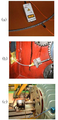
도 2는 종래에 사용되고 있는 비틀림 진동계측의 실시예들2 illustrates embodiments of torsional vibration measurement that are conventionally used.
<도면의 주요부분에 대한 부호의 설명><Description of the symbols for the main parts of the drawings>
(1) : 캠축(1): camshaft
(10) : 밴드(band)(10): band
(10a) : 천공10a: perforation
(20) : 근접센서(20): Proximity Sensor
본 발명은 스틸밴드를 이용한 캠축 비틀림 진동계측 장치에 관한 것으로, 보다 상세하게는 회전축의 설치환경에 제약 없이 간단히 설치되어 축계의 비틀림 상태를 정확히 감지할 수 있는 비틀림 진동계측 장치에 관한 것이다.The present invention relates to a camshaft torsional vibration measuring apparatus using a steel band, and more particularly, to a torsional vibration measuring apparatus that can be easily installed without limitation to the installation environment of the rotating shaft to accurately detect the torsional state of the shaft system.
최근 들어 내연기관의 복잡화를 구현하기 위해 기관 제어를 극대화시키기 위해서는 캠축, 피스톤, 크랭크축 등과 같은 기관 부품의 위치, 방향, 회전수, 부하 등 보다 정확한 정보를 획득하여야 하기 마련이다.Recently, in order to maximize engine control in order to realize the complexity of the internal combustion engine, it is necessary to acquire more accurate information such as the position, direction, rotation speed, and load of engine parts such as camshaft, piston, and crankshaft.
일반적으로, 축계(shafting system)의 비틀림 진동(torsional vibration)을 계측하는 방법에는 크게 스트레인 게이지(strain gauge)와 무선전송장비를 이용한 계측, 레이저 계측기(laser vibrometer)와 반사 테이프(reflecting tape)를 이용한 계측, 기어 또는 엔코더(rotary encoder)의 펄스(pulse)신호를 근접센서(proximity probe)로 검출하고 후처리를 통해 계측하는 방법들이 소개되고 있다.In general, the method of measuring the torsional vibration of the shafting system is largely measured using a strain gauge and a wireless transmission device, using a laser vibrometer and a reflecting tape. Methods of detecting pulse signals of measurement, gears or encoders with a proximity probe and measuring through post-processing have been introduced.
상기 스트레인게이지와 무선전송장비를 이용한 비틀림 진동계측은, 축계 상에 설치되어 연동하는 스트레인게이지와, 이 스트레인게이지를 통해 검출된 값을 수신하여 무선전송장비로 이루어지는데, 이는 축계의 변동응력(alternating stress)을 직접 계측할 수 있다는 장점이 있으나 가혹한 환경에서의 부정확성은 물론 무엇보다 그 설치비용이 가중되는 문제점이 발생하였다.The torsional vibration measurement using the strain gauge and the wireless transmission device, the strain gauge is installed on the shaft system and interlocked with the strain gauge, and receives the value detected through the strain gauge is composed of a wireless transmission device, which is an alternating stress (alternating) of the shaft system The stress can be measured directly, but inaccuracies in harsh environments as well as the installation cost of the problem was added above all.
아울러, 상기 레이저 계측기를 이용한 비틀림 진동계측은, 축계에 설치되어 연동하는 반사 테이프와, 이 반사 테이프의 변동정도를 감지하는 레이저 계측기로 이루어지는데, 무엇보다 이는 고가의 레이저 계측기를 필요로 한다는 문제점과 함께 특히 윤활유 등 비산물이 많은 가혹한 환경 하에서 반사테이프가 오염되어 정확한 검출값을 획득하기 곤란한 문제점이 발생되었다.In addition, the torsional vibration measurement using the laser measuring instrument is composed of a reflective tape installed in the shaft system and interlocked with the laser measuring instrument for detecting the degree of variation of the reflective tape, and above all, the problem of the need for an expensive laser measuring instrument and In addition, the reflecting tape is contaminated under severe environment, especially in the presence of a large number of by-products such as lubricating oil, a problem that it is difficult to obtain an accurate detection value.
마지막으로, 도 2는 상기 근접센서를 이용하여 축계로부터 펄스신호의 변동을 계측하는 방식의 예들을 도시한 것으로, 이는 축계 상에 설치되어 연동하는 기 어(도 1b도면), 엔코더의 회전에 따른 펄스신호를 검출하는 근접센서를 이용하는 방식(도 1c도면 참조) 등이 있으며, 또한, 이러한 반복된 펄스신호를 이용하기 위한 수단으로 속칭 "얼룩말띠(zebra tape)"라고 불리는 블랙 앤 화이트 띠(black & white tape)를 축계에 설치하여, 반복하여 교번되는 색의 펄스신호를 감지하는 적외선 혹은 레이저센서를 이용하는 방식(도 1a도면 참조)들이 있다.Finally, Figure 2 shows an example of a method of measuring the variation of the pulse signal from the shaft system by using the proximity sensor, which is installed on the shaft system (Fig. 1b), according to the rotation of the encoder There is a method using a proximity sensor that detects a pulse signal (see FIG. 1C), and a black and white band called “zebra tape” as a means for using such a repeated pulse signal. & white tape) is installed in the shaft system, and there are methods using an infrared or laser sensor that repeatedly detects a pulse signal of alternating colors (see FIG. 1A).
하지만, 상기 회전하는 기어치의 펄스신호를 이용하는 방식(도 1b도면)은 축계에 연결되어 설치될 수 있어야만 하는 설치 상의 제한이 있었으며, 특히, 상기 블랙 앤 화이트 띠의 경우(도 1a도면)에는 윤활유가 채워진 환경 하에서 축계에 설치될 시에는 비산된 윤활유에 의해 띠의 반복된 색의 구분이 불가능한 문제점이 발생하게 되었다.However, the method of using the pulse signal of the rotating gear teeth (Fig. 1b) has a limit on the installation must be connected to the shaft system, in particular, in the case of the black and white strip (Fig. 1a) is a lubricant When installed in a shaft system under a filled environment, a problem arises in that it is impossible to distinguish the color of the strip repeatedly due to scattered lubricant.
본 발명은 상기와 같은 종래의 문제점을 해결하기 위한 것으로, 그 목적은 축계가 설치되는 환경의 제약, 즉 축 상에 설치되어 회전영역에 대한 주위 부재로부터 간섭을 배제시키고, 또한 윤활유 등에 의한 감지수단의 오염과 변질을 미연에 배제시킬 수 있는 것이며, 아울러 그 설치제작비용 및 작업공수를 절감할 수 있는 비틀림 계측장치를 제공함에 있다.The present invention is to solve the above conventional problems, the object of which is to limit the environment in which the shaft system is installed, that is installed on the shaft to exclude the interference from the surrounding member to the rotation region, and also the sensing means by the lubricant, etc. It is to provide a torsion measuring device that can eliminate contamination and deterioration of wastes in advance, and can reduce installation cost and workmanship.
상기한 바와 같은 목적을 달성하고 종래의 결점을 제거하기 위한 본 발명은 캠축의 외면에 감겨진 채 고정되어, 등간격의 천공을 구비하는 밴드와, 이 밴드로부터 근접 배치되어 캠축과 연동 회전하는 천공으로부터 펄스신호를 검출하는 근접센서를 포함하여 이루어진 것을 특징으로 한다.The present invention for achieving the object as described above and to eliminate the conventional defects is fixed to the outer surface of the cam shaft, the band is provided with equally spaced perforations, and the perforated rotation is interlocked with the cam shaft disposed in close proximity to the band It characterized in that it comprises a proximity sensor for detecting a pulse signal from.
이때 상기 밴드는 금속재질로 이루어지며, 상기 근접센서는 마그네틱(magnet) 또는 와전류(eddy current) 타입의 센서인 것을 특징으로 한다.In this case, the band is made of a metal material, the proximity sensor is characterized in that the sensor of the magnetic (magnet) or eddy current type (eddy current) type.
이하, 본 발명의 실시예를 첨부도면과 연계하여 상세히 설명하면 다음과 같다.Hereinafter, an embodiment of the present invention will be described in detail with reference to the accompanying drawings.
도 1은 본 발명에 따른 캠축 비틀림 진동계측 장치의 구성을 보이는 개략도로서, 본 발명에 따른 캠축 비틀림 계측 장치는, 피스톤과 연결된 크랭크축 등의 출력으로부터 연동 회전하는 캠축(1)의 외면에 감겨져 고정되며, 그 길이방향을 따라 등간격의 천공(10a)부를 형성하는 밴드(10)와, 이 밴드(10)로부터 근접하게 배치되어 캠축(1)과 연동 회전 시 천공(10a)부의 회전정도를 펄스신호로 감지하는 근접센서(20)로 이루어진다.1 is a schematic view showing the configuration of a camshaft torsional vibration measuring apparatus according to the present invention, wherein the camshaft torsion measuring apparatus according to the present invention is wound around and fixed on the outer surface of the
바람직하게는, 상기 밴드(10)의 재질은 금속재질로 하여, 캠축(1) 상에 예컨대 점용접(spot welding)으로 일체화 하며, 이때 금속재질의 밴드(10)에 형성된 천공(10a)부를 감지하기 위한 근접센서(20)는 마그네틱 또는 와전류 타입 센서들로 구성하도록 한다.Preferably, the
이러한 근접센서(20)는, 금속대상물(밴드:10)의 자기, 자계의 변화정도를 감지하는 것으로, 금속 모재까지의 정밀 변위 측정 및 모재 내부의 이상을 감지하는 탐상에 쓰이는 대표적 센서로서, 그 기본원리는 센서 내 코일부에 인가되는 전류의 세기 및 주파수에 비례하여 자기장이 형성되고 그 자기장에 의해 금속대상물의 표면에 와전류가 발생하는데 발생한 와전류에 의해 센서의 코일부에서 발생한 자기장의 방향에 반대 방향의 자기장이 형성되고 결국 센서 코일부의 임피던스의 변화를 초래하고 그 임피던스 변화의 측정으로 센싱하게 되는 구조를 이루게 된다.The
이러한 근접센서는 금속대상물, 즉 본 발명에 따른 금속재질의 밴드(10)에 형성된 천공(10a)부의 두께가 1 mm 이하일 경우라 하더라도 정확히 계측할 수 있는 장점을 가지는 것이다.Such a proximity sensor has an advantage that can be accurately measured even if the thickness of the perforated 10a formed in the metal object, that is, the
상기와 같은 본 발명의 계측장치는 기존의 축 상에 엔코더, 혹은 기어 등을 설치하기 곤란하거나 불가한 경우 적용할 수 있도록 한 것이며, 특히 윤활유로 채워진 상태에서 회전하는 캠축과 같은 경우 비산되거나 고온을 유지하게 되는 윤활유로부터 근접센서(20)의 감지대상이 되는 밴드(10)측 천공(10a)부의 미확인상태나 변질된 상태의 염려를 해소할 수 있는 것이다.The measuring device of the present invention as described above is to be applied when it is difficult or impossible to install an encoder or a gear on an existing shaft, especially in the case of a cam shaft that rotates in a state filled with lubricating oil, such as scattering or high temperature From the lubricating oil to be maintained, it is possible to eliminate the concern of the unidentified state or the deteriorated state of the perforated 10a portion of the
나아가 이러한 구조는 장시간 사용 시, 별다른 유지보수의 추가 작업을 요하지 않은 상태로 지속적인 계측을 수행할 수 있는 것이다.Furthermore, this structure allows continuous measurements to be carried out over long periods of time without requiring additional maintenance.
아울러, 본 발명에 따른 축 비틀림 계측 장치는, 내연기관에 설치되는 캠축에 국한되는 것이 아니라, 모터, 펌프, 터빈 등 가정용 산업용 회전 구동축의 토크력을 측정하는 많은 응용분야에 적용 가능할 것으로 여겨진다.In addition, the shaft torsion measuring apparatus according to the present invention is not limited to the cam shaft installed in the internal combustion engine, and is considered to be applicable to many applications for measuring the torque force of the rotary drive shaft for domestic industrial use such as a motor, a pump, a turbine, and the like.
상술한 바와 같이 본 발명은 계측 대상이 되는 축의 회전에 따른 설치 간섭에 영향을 받지 않으며, 특히 윤활유로 채워진 상태의 캠축에서와 같이 비산되거나 고온상태를 유지하게 되는 윤활유로부터 감지수단이 오염되거나 변질되는 염려를 해소함으로서, 별다른 유지보수 없이 지속적인 정밀 계측이 가능한 것이다.As described above, the present invention is not affected by the installation interference due to the rotation of the axis to be measured, and in particular, the sensing means is contaminated or deteriorated from the lubricant which is scattered or maintained at a high temperature, such as in a camshaft filled with lubricant. By eliminating concerns, continuous precision measurement is possible without any maintenance.
또한, 저렴한 감지수단과 간단한 설치작업을 통해, 작업공수 및 제작비를 절감할 수 있는 효과가 있는 것이다.In addition, through the low-cost sensing means and simple installation, there is an effect that can reduce the labor and manufacturing costs.
Claims (2)
Priority Applications (1)
| Application Number | Priority Date | Filing Date | Title |
|---|---|---|---|
| KR1020070043420A KR20080098131A (en) | 2007-05-04 | 2007-05-04 | Camshaft Torsional Vibration Measurement Device Using Steel Band |
Applications Claiming Priority (1)
| Application Number | Priority Date | Filing Date | Title |
|---|---|---|---|
| KR1020070043420A KR20080098131A (en) | 2007-05-04 | 2007-05-04 | Camshaft Torsional Vibration Measurement Device Using Steel Band |
Publications (1)
| Publication Number | Publication Date |
|---|---|
| KR20080098131A true KR20080098131A (en) | 2008-11-07 |
Family
ID=40285713
Family Applications (1)
| Application Number | Title | Priority Date | Filing Date |
|---|---|---|---|
| KR1020070043420A Ceased KR20080098131A (en) | 2007-05-04 | 2007-05-04 | Camshaft Torsional Vibration Measurement Device Using Steel Band |
Country Status (1)
| Country | Link |
|---|---|
| KR (1) | KR20080098131A (en) |
Cited By (2)
| Publication number | Priority date | Publication date | Assignee | Title |
|---|---|---|---|---|
| US9176024B2 (en) | 2013-10-23 | 2015-11-03 | General Electric Company | Systems and methods for monitoring rotary equipment |
| CN107389181A (en) * | 2017-08-25 | 2017-11-24 | 杭州电子科技大学 | A kind of torsional oscillation detection method and its sensor of application |
-
2007
- 2007-05-04 KR KR1020070043420A patent/KR20080098131A/en not_active Ceased
Cited By (3)
| Publication number | Priority date | Publication date | Assignee | Title |
|---|---|---|---|---|
| US9176024B2 (en) | 2013-10-23 | 2015-11-03 | General Electric Company | Systems and methods for monitoring rotary equipment |
| CN107389181A (en) * | 2017-08-25 | 2017-11-24 | 杭州电子科技大学 | A kind of torsional oscillation detection method and its sensor of application |
| CN107389181B (en) * | 2017-08-25 | 2019-08-06 | 杭州电子科技大学 | A kind of torsional oscillation detection method and its sensor of application |
Similar Documents
| Publication | Publication Date | Title |
|---|---|---|
| US6600310B2 (en) | Linear and rotary magnetic sensor | |
| CN104160269B (en) | Monitor engine components | |
| US5412999A (en) | Position sensing with magnetostrictive stress sensor | |
| ES2434115T3 (en) | Procedure and device for monitoring a drive line that has a high elastic coupling | |
| RU2527673C2 (en) | Method to detect structural defect in mechanical unit comprising rotary element | |
| US4589290A (en) | Torque sensor | |
| US7034522B2 (en) | Method and apparatus for measuring movement, displacement and/or deformation | |
| US7234684B2 (en) | Hoisting device with load measuring mechanism and method for determining the load of hoisting devices | |
| US20070051188A1 (en) | Measurement of torsional dynamics of rotating shafts using magnetostrictive sensors | |
| JP2013505434A (en) | Device for obtaining angle signals | |
| JP2009504997A (en) | Piston internal combustion engine and method for detecting the wear value of a transmission element arranged between a crankshaft and a camshaft | |
| Janssens et al. | Comparison of torsional vibration measurement techniques | |
| KR102205769B1 (en) | Torque sensor | |
| US9091703B2 (en) | Measurement of shaft speed, angular displacement, position or movement | |
| US7237444B2 (en) | Torque cell for determining a torque load on a rotary member | |
| US8429958B2 (en) | Apparatus and method for monitoring sliding state of piston | |
| CN100575883C (en) | Angle measuring device | |
| KR20080098131A (en) | Camshaft Torsional Vibration Measurement Device Using Steel Band | |
| US20100282002A1 (en) | Measuring device for detecting the operating state of a shaft, method and shaft arrangement comprising said measuring device | |
| WO2001038885A1 (en) | Angular velocity monitor | |
| KR102813833B1 (en) | An Apparatus for Measuring a Shaft Revolution of a Ship with Easy Coupling Property and with a Property Unaffected to a Pollution and a Vibration and a Method for the Same | |
| JP6029888B2 (en) | Motor diagnostic device, method and program | |
| GB2385425A (en) | A method of monitoring a load on a gearbox | |
| WO1998034455A2 (en) | Measurement of torsional dynamics of rotating shafts using magnetostrictive sensors | |
| JPH0635666U (en) | Bearing with sensor |
Legal Events
| Date | Code | Title | Description |
|---|---|---|---|
| PA0109 | Patent application |
Patent event code: PA01091R01D Comment text: Patent Application Patent event date: 20070504 |
|
| PG1501 | Laying open of application | ||
| A201 | Request for examination | ||
| PA0201 | Request for examination |
Patent event code: PA02012R01D Patent event date: 20120423 Comment text: Request for Examination of Application Patent event code: PA02011R01I Patent event date: 20070504 Comment text: Patent Application |
|
| E902 | Notification of reason for refusal | ||
| PE0902 | Notice of grounds for rejection |
Comment text: Notification of reason for refusal Patent event date: 20130523 Patent event code: PE09021S01D |
|
| E601 | Decision to refuse application | ||
| PE0601 | Decision on rejection of patent |
Patent event date: 20130905 Comment text: Decision to Refuse Application Patent event code: PE06012S01D Patent event date: 20130523 Comment text: Notification of reason for refusal Patent event code: PE06011S01I |