KR20080058370A - Method of making a privacy film - Google Patents
Method of making a privacy film Download PDFInfo
- Publication number
- KR20080058370A KR20080058370A KR1020087008634A KR20087008634A KR20080058370A KR 20080058370 A KR20080058370 A KR 20080058370A KR 1020087008634 A KR1020087008634 A KR 1020087008634A KR 20087008634 A KR20087008634 A KR 20087008634A KR 20080058370 A KR20080058370 A KR 20080058370A
- Authority
- KR
- South Korea
- Prior art keywords
- channel
- light
- polymeric material
- light directing
- channels
- Prior art date
Links
Images


Classifications
-
- B—PERFORMING OPERATIONS; TRANSPORTING
- B29—WORKING OF PLASTICS; WORKING OF SUBSTANCES IN A PLASTIC STATE IN GENERAL
- B29C—SHAPING OR JOINING OF PLASTICS; SHAPING OF MATERIAL IN A PLASTIC STATE, NOT OTHERWISE PROVIDED FOR; AFTER-TREATMENT OF THE SHAPED PRODUCTS, e.g. REPAIRING
- B29C33/00—Moulds or cores; Details thereof or accessories therefor
- B29C33/42—Moulds or cores; Details thereof or accessories therefor characterised by the shape of the moulding surface, e.g. ribs or grooves
- B29C33/424—Moulding surfaces provided with means for marking or patterning
-
- B—PERFORMING OPERATIONS; TRANSPORTING
- B29—WORKING OF PLASTICS; WORKING OF SUBSTANCES IN A PLASTIC STATE IN GENERAL
- B29C—SHAPING OR JOINING OF PLASTICS; SHAPING OF MATERIAL IN A PLASTIC STATE, NOT OTHERWISE PROVIDED FOR; AFTER-TREATMENT OF THE SHAPED PRODUCTS, e.g. REPAIRING
- B29C33/00—Moulds or cores; Details thereof or accessories therefor
- B29C33/42—Moulds or cores; Details thereof or accessories therefor characterised by the shape of the moulding surface, e.g. ribs or grooves
-
- B—PERFORMING OPERATIONS; TRANSPORTING
- B29—WORKING OF PLASTICS; WORKING OF SUBSTANCES IN A PLASTIC STATE IN GENERAL
- B29C—SHAPING OR JOINING OF PLASTICS; SHAPING OF MATERIAL IN A PLASTIC STATE, NOT OTHERWISE PROVIDED FOR; AFTER-TREATMENT OF THE SHAPED PRODUCTS, e.g. REPAIRING
- B29C43/00—Compression moulding, i.e. applying external pressure to flow the moulding material; Apparatus therefor
- B29C43/02—Compression moulding, i.e. applying external pressure to flow the moulding material; Apparatus therefor of articles of definite length, i.e. discrete articles
-
- B—PERFORMING OPERATIONS; TRANSPORTING
- B29—WORKING OF PLASTICS; WORKING OF SUBSTANCES IN A PLASTIC STATE IN GENERAL
- B29C—SHAPING OR JOINING OF PLASTICS; SHAPING OF MATERIAL IN A PLASTIC STATE, NOT OTHERWISE PROVIDED FOR; AFTER-TREATMENT OF THE SHAPED PRODUCTS, e.g. REPAIRING
- B29C59/00—Surface shaping of articles, e.g. embossing; Apparatus therefor
- B29C59/02—Surface shaping of articles, e.g. embossing; Apparatus therefor by mechanical means, e.g. pressing
- B29C59/022—Surface shaping of articles, e.g. embossing; Apparatus therefor by mechanical means, e.g. pressing characterised by the disposition or the configuration, e.g. dimensions, of the embossments or the shaping tools therefor
-
- G—PHYSICS
- G02—OPTICS
- G02B—OPTICAL ELEMENTS, SYSTEMS OR APPARATUS
- G02B5/00—Optical elements other than lenses
-
- B—PERFORMING OPERATIONS; TRANSPORTING
- B29—WORKING OF PLASTICS; WORKING OF SUBSTANCES IN A PLASTIC STATE IN GENERAL
- B29C—SHAPING OR JOINING OF PLASTICS; SHAPING OF MATERIAL IN A PLASTIC STATE, NOT OTHERWISE PROVIDED FOR; AFTER-TREATMENT OF THE SHAPED PRODUCTS, e.g. REPAIRING
- B29C59/00—Surface shaping of articles, e.g. embossing; Apparatus therefor
- B29C59/02—Surface shaping of articles, e.g. embossing; Apparatus therefor by mechanical means, e.g. pressing
- B29C59/022—Surface shaping of articles, e.g. embossing; Apparatus therefor by mechanical means, e.g. pressing characterised by the disposition or the configuration, e.g. dimensions, of the embossments or the shaping tools therefor
- B29C2059/023—Microembossing
-
- Y—GENERAL TAGGING OF NEW TECHNOLOGICAL DEVELOPMENTS; GENERAL TAGGING OF CROSS-SECTIONAL TECHNOLOGIES SPANNING OVER SEVERAL SECTIONS OF THE IPC; TECHNICAL SUBJECTS COVERED BY FORMER USPC CROSS-REFERENCE ART COLLECTIONS [XRACs] AND DIGESTS
- Y10—TECHNICAL SUBJECTS COVERED BY FORMER USPC
- Y10S—TECHNICAL SUBJECTS COVERED BY FORMER USPC CROSS-REFERENCE ART COLLECTIONS [XRACs] AND DIGESTS
- Y10S283/00—Printed matter
- Y10S283/901—Concealed data
-
- Y—GENERAL TAGGING OF NEW TECHNOLOGICAL DEVELOPMENTS; GENERAL TAGGING OF CROSS-SECTIONAL TECHNOLOGIES SPANNING OVER SEVERAL SECTIONS OF THE IPC; TECHNICAL SUBJECTS COVERED BY FORMER USPC CROSS-REFERENCE ART COLLECTIONS [XRACs] AND DIGESTS
- Y10—TECHNICAL SUBJECTS COVERED BY FORMER USPC
- Y10S—TECHNICAL SUBJECTS COVERED BY FORMER USPC CROSS-REFERENCE ART COLLECTIONS [XRACs] AND DIGESTS
- Y10S283/00—Printed matter
- Y10S283/902—Anti-photocopy
-
- Y—GENERAL TAGGING OF NEW TECHNOLOGICAL DEVELOPMENTS; GENERAL TAGGING OF CROSS-SECTIONAL TECHNOLOGIES SPANNING OVER SEVERAL SECTIONS OF THE IPC; TECHNICAL SUBJECTS COVERED BY FORMER USPC CROSS-REFERENCE ART COLLECTIONS [XRACs] AND DIGESTS
- Y10—TECHNICAL SUBJECTS COVERED BY FORMER USPC
- Y10S—TECHNICAL SUBJECTS COVERED BY FORMER USPC CROSS-REFERENCE ART COLLECTIONS [XRACs] AND DIGESTS
- Y10S428/00—Stock material or miscellaneous articles
- Y10S428/916—Fraud or tamper detecting
-
- Y—GENERAL TAGGING OF NEW TECHNOLOGICAL DEVELOPMENTS; GENERAL TAGGING OF CROSS-SECTIONAL TECHNOLOGIES SPANNING OVER SEVERAL SECTIONS OF THE IPC; TECHNICAL SUBJECTS COVERED BY FORMER USPC CROSS-REFERENCE ART COLLECTIONS [XRACs] AND DIGESTS
- Y10—TECHNICAL SUBJECTS COVERED BY FORMER USPC
- Y10T—TECHNICAL SUBJECTS COVERED BY FORMER US CLASSIFICATION
- Y10T428/00—Stock material or miscellaneous articles
- Y10T428/14—Layer or component removable to expose adhesive
-
- Y—GENERAL TAGGING OF NEW TECHNOLOGICAL DEVELOPMENTS; GENERAL TAGGING OF CROSS-SECTIONAL TECHNOLOGIES SPANNING OVER SEVERAL SECTIONS OF THE IPC; TECHNICAL SUBJECTS COVERED BY FORMER USPC CROSS-REFERENCE ART COLLECTIONS [XRACs] AND DIGESTS
- Y10—TECHNICAL SUBJECTS COVERED BY FORMER USPC
- Y10T—TECHNICAL SUBJECTS COVERED BY FORMER US CLASSIFICATION
- Y10T428/00—Stock material or miscellaneous articles
- Y10T428/24—Structurally defined web or sheet [e.g., overall dimension, etc.]
- Y10T428/24355—Continuous and nonuniform or irregular surface on layer or component [e.g., roofing, etc.]
- Y10T428/24372—Particulate matter
-
- Y—GENERAL TAGGING OF NEW TECHNOLOGICAL DEVELOPMENTS; GENERAL TAGGING OF CROSS-SECTIONAL TECHNOLOGIES SPANNING OVER SEVERAL SECTIONS OF THE IPC; TECHNICAL SUBJECTS COVERED BY FORMER USPC CROSS-REFERENCE ART COLLECTIONS [XRACs] AND DIGESTS
- Y10—TECHNICAL SUBJECTS COVERED BY FORMER USPC
- Y10T—TECHNICAL SUBJECTS COVERED BY FORMER US CLASSIFICATION
- Y10T428/00—Stock material or miscellaneous articles
- Y10T428/24—Structurally defined web or sheet [e.g., overall dimension, etc.]
- Y10T428/24479—Structurally defined web or sheet [e.g., overall dimension, etc.] including variation in thickness
- Y10T428/2457—Parallel ribs and/or grooves
-
- Y—GENERAL TAGGING OF NEW TECHNOLOGICAL DEVELOPMENTS; GENERAL TAGGING OF CROSS-SECTIONAL TECHNOLOGIES SPANNING OVER SEVERAL SECTIONS OF THE IPC; TECHNICAL SUBJECTS COVERED BY FORMER USPC CROSS-REFERENCE ART COLLECTIONS [XRACs] AND DIGESTS
- Y10—TECHNICAL SUBJECTS COVERED BY FORMER USPC
- Y10T—TECHNICAL SUBJECTS COVERED BY FORMER US CLASSIFICATION
- Y10T428/00—Stock material or miscellaneous articles
- Y10T428/25—Web or sheet containing structurally defined element or component and including a second component containing structurally defined particles
Landscapes
- Engineering & Computer Science (AREA)
- Mechanical Engineering (AREA)
- Physics & Mathematics (AREA)
- General Physics & Mathematics (AREA)
- Optics & Photonics (AREA)
- Laminated Bodies (AREA)
- Optical Elements Other Than Lenses (AREA)
- Planar Illumination Modules (AREA)
- Devices For Indicating Variable Information By Combining Individual Elements (AREA)
- Moulds For Moulding Plastics Or The Like (AREA)
- Casting Or Compression Moulding Of Plastics Or The Like (AREA)
Abstract
Description
본 발명은 프라이버시 필름에 관한 것이다. 특히, 본 발명은 복수의 광 지향 요소(light directing element)를 갖는 중합체계 프라이버시 필름에 관한 것으로, 각각의 광 지향 요소는 다음의 인접한 광 지향 요소와 사실상 평행하게 배치되고, 필름은 문서와 함께 사용되기에 적합하다.The present invention relates to a privacy film. In particular, the present invention relates to a polymer based privacy film having a plurality of light directing elements, each light directing element disposed substantially parallel to the next adjacent light directing element, the film being used with the document. It is suitable to be.
소비자에 대해 프라이버시를 제공할 수 있는 제품들이 증가하였다. 예를 들어, 오늘날에는 대부분의 개인용 컴퓨터 및 자동 현금 지급기가, 모니터 상의 이미지를 사용자가 볼 수 있게 함과 동시에 옆에서 보고 있는 사람 또는 적어도 스크린의 시야각 내에 있지 않은 사람들이 보는 것을 제한하는 프라이버시 스크린을 포함하는 것이 매우 통상적이다. 일부는 기밀 자료를 포함한 문서를 갖는 사용자에게 프라이버시를 제공하기 위해 광 제어 필름을 사용하였다. 이러한 아이디어는 사용자가 문서 상의 이미지를 볼 수 있지만 옆에서 보고 있는 사람이 문서의 내용을 보는 데 있어서 제한된다는 점에서 유사하다.There is an increasing number of products that can provide privacy to consumers. For example, today, most personal computers and automatic teller machines have privacy screens that allow users to view images on the monitor while limiting what they see next to them or at least not those who are not within the viewing angle of the screen. It is very common to include. Some have used light control films to provide privacy to users with documents containing confidential data. This idea is similar in that the user can see the image on the document, but the person viewing the side is limited in viewing the contents of the document.
해당 기술은 사용자에게 프라이버시를 제공하는 목적을 또한 충족시키는 다양한 광 제어 필름을 개시한다. 그러나, 문서의 프라이버시에 대한 소비자의 요구가 점점 더 커짐에 따라, 당업자는 이러한 요구되는 특징을 제공하기 위해 다른 해 결책을 찾고 있다. 따라서, 새로운 프라이버시 필름 구성에 대한 지속적인 필요성이 존재한다.The technology discloses various light control films that also fulfill the purpose of providing privacy to the user. However, as consumer demand for document privacy increases, those skilled in the art are looking for other solutions to provide these required features. Thus, there is a continuing need for new privacy film configurations.
발명의 개요Summary of the Invention
본 발명은 바라보는 사람이 문서 상의 정보를 읽을 수 있는 각도를 제한하도록 문서와 함께 사용될 수 있는 프라이버시 필름을 제공한다. 특히, 시야각이 사용자의 시선과 일치하도록 프라이버시 필름이 사용 배향으로 위치되면, 사용자는 문서의 내용을 볼 수 있지만, 다른 사람들은 문서의 내용을 제한적으로만 볼 수 있게 된다.The present invention provides a privacy film that can be used with a document to limit the angle at which the viewer can read the information on the document. In particular, when the privacy film is positioned in the use orientation so that the viewing angle coincides with the line of sight of the user, the user can view the contents of the document, while others can only view the contents of the document in a limited way.
일 태양에 있어서, 본 발명은 (i) 제1 중합체 재료를 포함하고 대향하는 제1 및 제2 표면을 갖는 광 투과성 중합체계 기부 시트(base sheet); 및 (ii) 제2 중합체 재료를 포함하는 복수의 광 지향 요소를 포함하며, 각각의 요소는 기부와, 높이(h)와, 높이를 따라 배치되는 단축을 가지며, 요소들은 기부 시트의 제1 표면으로부터 돌출하고, 각각의 요소는 하나의 요소의 단축이 다음 인접한 요소의 단축에 사실상 평행하고 하나의 요소의 기부가 다음 인접한 요소의 기부와 연결되지 않도록 배치되는 프라이버시 필름에 관한 것이다. 다른 태양에 있어서, 프라이버시 필름은 긴 광 지향 요소들을 포함한다.In one aspect, the present invention provides an optically transparent polymer base sheet comprising (i) a first polymeric material and having opposing first and second surfaces; And (ii) a plurality of light directing elements comprising a second polymer material, each element having a base, a height h and a short axis disposed along the height, the elements having a first surface of the base sheet. Protruding from, each element relates to a privacy film that is arranged such that the short axis of one element is substantially parallel to the short axis of the next adjacent element and that the base of one element is not connected to the base of the next adjacent element. In another aspect, the privacy film includes long light directing elements.
다른 태양에 있어서, 본 발명은 (i) 중합체 재료를 제공하는 단계; (ii) 사실상 평행한 긴 복수의 채널 - 각각의 채널은 경사지고 랜드 영역에 의해 다음 채널로부터 각각 분리되고, 각각의 채널은 랜드 영역에 인접하게 배치된 기부 및 랜드 영역으로부터 멀리 배치된 팁을 가지며, 각각의 채널은 기부로부터 팁까지 연장 되는 단축을 가짐 - 을 포함하는 미세구조화된 주형 상에 중합체 재료를 침착하는 단계; (iii) 중합체 재료를 미세구조화된 주형의 채널들 내로 유동하도록 유도하는 단계; (iv) 중합체 재료를 채널들 내부에서 응고시켜, 복수의 광 지향 요소들 - 광 지향 요소들은 광 지향 요소들이 돌출한 제1 표면 및 대향하는 사실상 평탄한 제2 표면을 갖는 중합체 기부 시트를 통해 서로 연결됨 - 을 생성하는 단계; 및 (v) 프라이버시 필름을 미세구조화된 주형로부터 분리하는 단계를 포함하는, 프라이버시 필름의 제조 방법에 관한 것이다. In another aspect, the present invention provides a method for producing a polymeric material comprising: (i) providing a polymeric material; (ii) a plurality of substantially parallel long channels, each channel being inclined and separated from the next channel by a land area respectively, each channel having a tip disposed away from the base and land areas disposed adjacent to the land area; Depositing polymeric material on the microstructured mold, wherein each channel has a short axis extending from the base to the tip; (iii) directing the polymeric material to flow into the channels of the microstructured mold; (iv) solidifying the polymer material inside the channels such that a plurality of light directing elements, the light directing elements are connected to each other via a polymer base sheet having a first surface on which the light directing elements protrude and an opposite substantially flat second surface Generating a; And (v) separating the privacy film from the microstructured mold.
본 명세서에 사용된 바와 같이, "광 투과성"이라는 용어는 가시광을 투과시키는 능력을 의미한다. 하나의 실시 형태에 있어서, 광 투과성 기부 시트는 미국 버지니아주 레스톤 소재의 헌터 어소시에이츠 래버러토리, 인크.(Hunter Associates Laboratory, Inc.)로부터 구매 가능한 헌터랩 마스터 컬러 데이터 프로그램(HuterLab Master Color Data Program)을 갖춘 랩 스캔 6000 테스터(Lab Scan 6000 Tester)를 사용하여 측정하였을 때 90 이하의 불투명도를 갖는다. 광 지향 요소와 관련하여, "긴"이라는 용어는 요소가 일반적으로 레일형 외양을 가짐을 의미한다. 레일은 프라이버시 필름의 전체 길이를 따라 연속적이거나 불연속적일 수 있다. 하나의 실시 형태에 있어서, 불연속적인 광 지향 요소는 예를 들어 버섯의 대(stem)와 같은 스템의 외양을 갖는 별개 몸체이다. As used herein, the term "light transmissive" means the ability to transmit visible light. In one embodiment, the light transmissive base sheet is a HunterLab Master Color Data Program available from Hunter Associates Laboratory, Inc., Reston, VA. It has an opacity of less than 90 when measured using a Lab Scan 6000 Tester. In the context of a light directing element, the term "long" means that the element generally has a railed appearance. The rail may be continuous or discontinuous along the entire length of the privacy film. In one embodiment, the discontinuous light directing element is a separate body having the appearance of a stem, for example a stem of a mushroom.
본 발명의 하나의 이점은 제조가 비교적 용이한 가요성 구성을 갖는 프라이버시 특징부를 제공한다는 것이다. 프라이버시 필름은 문서에 비영구적인 방식으로 신속하게 부착될 수 있다. 더욱이, 프라이버시 필름은 반복적으로 사용될 수 있도록 내구적이다.One advantage of the present invention is that it provides privacy features with a flexible configuration that is relatively easy to manufacture. The privacy film can be quickly attached to the document in a non-permanent manner. Moreover, privacy films are durable so that they can be used repeatedly.
본 문서에서, "약"이라는 용어는 모든 수치 값을 완화시키는 것으로 여겨진다.In this document, the term "about" is considered to mitigate all numerical values.
본 발명은 이하의 도면을 참조하여 보다 잘 이해될 수 있다.The invention can be better understood with reference to the following figures.
도 1은 프라이버시 필름의 하나의 예시적인 실시 형태의 사시도.1 is a perspective view of one exemplary embodiment of a privacy film.
도 2는 선 2-2를 따라 취한 도 1의 프라이버시 필름의 단면도.2 is a cross-sectional view of the privacy film of FIG. 1 taken along line 2-2.
도 3은 복수의 섹션들을 갖는 광 지향 요소들을 도시한, 프라이버시 필름의 다른 예시적인 실시 형태의 단면도.3 is a cross-sectional view of another exemplary embodiment of a privacy film, showing light directing elements having a plurality of sections.
도 4는 광 흡수 코팅으로 덮인 광 지향 요소들의 팁 부분들을 도시한, 프라이버시 필름의 다른 예시적인 실시 형태의 단면도.4 is a cross-sectional view of another exemplary embodiment of a privacy film, showing tip portions of light directing elements covered with a light absorbing coating.
도 5는 변화하는 경사각의 광 지향 요소들을 도시한, 프라이버시 필름의 다른 예시적인 실시 형태의 단면도.5 is a cross-sectional view of another exemplary embodiment of a privacy film, showing light directing elements of varying tilt angles.
도 6은 기부층에 평행한 방향으로 긴 광 지향 요소들의 팁 부분들을 도시한, 프라이버시 필름의 다른 예시적인 실시 형태의 단면도.FIG. 6 is a cross-sectional view of another exemplary embodiment of a privacy film, showing tip portions of elongate light directing elements in a direction parallel to the base layer. FIG.
도 7은 긴 광 지향 요소들의 조합을 도시한, 프라이버시 필름의 다른 예시적인 실시 형태의 사시도.7 is a perspective view of another exemplary embodiment of a privacy film, showing a combination of long light directing elements.
도 8a 내지 도 8c는 프라이버시 필름을 제조하는 데에 사용될 수 있는 예시적인 공정의 개략도.8A-8C are schematic diagrams of example processes that can be used to make privacy films.
이들 도면들은 축척에 맞게 그려지지 않았으며 단지 예시적인 목적을 위해 의도된 것이다.These drawings are not drawn to scale and are intended for illustrative purposes only.
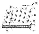
도 1은 기밀 정보를 포함할 수 있는 기판(substrate, 50) 상에 배치된 긴 광 지향 요소(18)를 갖는 프라이버시 필름(10)을 도시한 본 발명의 하나의 예시적인 실시 형태의 사시도이다. 하나의 실시 형태에 있어서, 프라이버시 필름은 광 투과성 접착제(도시되지 않음)를 사용하여 부착될 수 있다. 요소들은 장축(L)과 단축(ℓ)을 갖는다. 하나의 예시적인 기판은 보기 위한 접근이 제한되기를 문서 소유자가 원하는 비밀 정보를 지닌 문서이다. 1 is a perspective view of one exemplary embodiment of the present invention showing a
사용시, 본 발명의 프라이버시 필름은 장축(L)이 문서 상의 이미지 또는 텍스트 행에 사실상 평행하게 놓이도록 문서 상에 배치된다. 예를 들어, 텍스트가 종이의 21.6 ㎝(8½ 인치) 변에 사실상 평행하게 놓이는 세로 배향의 21.6 ㎝(8½ 인치) x 28 ㎝(11 인치) 종이 상에, 프라이버시 필름은 장축이 또한 동일한 방향을 따라 놓이도록 배향될 것이다. 프라이버시 필름은, 필름이 문서에 손상을 주지 않으면서 기판으로부터 제거될 수 있음을 의미하는 것으로서 문서 상에 일시적으로 배치될 수 있거나, 프라이버시 필름의 제거가 문서에 손상을 일으킬 가능성이 매우 큼을 의미하는 것으로서 영구적으로 배치될 수 있다. 프라이버시 필름을 문서에 부착하거나 배치하기 위한 다양한 수단이 존재한다. 예를 들어, 접착제가 사용될 수 있다. 접착제는 감압성(pressure sensitive) 또는 고온 용융성일 수 있다. 접착제는 재부착가능 접착체일 수 있는데, 이는 기판을 손상시키지 않고 재부착가능 접착제의 점착력을 현저히 상실하지 않으면서 수 회 기판에 도포되고 이로부터 제거될 수 있음을 의미한다. 다른 응용에서, 프라이버시 필름은 포켓으로서 형성될 수 있는데, 이 경우 프라이버시 필름이 전방의 중합체 배킹(backing)을 형성하거나 프라이버시 필름이 배면을 형성하고, 프라이버시 필름 및 배면이 3개의 변에서 부착되고 문서의 삽입 및 제거를 위해 제4 변, 통상적으로 상부 변을 개방된 상태로 남겨둔다. 다른 구성이 사용될 수 있다.In use, the privacy film of the present invention is disposed on the document such that the long axis L lies substantially parallel to the image or text line on the document. For example, on a 21.6 cm (8½ inch) x 28 cm (11 inch) paper of longitudinal orientation where the text lies substantially parallel to the 21.6 cm (8½ inch) side of the paper, the privacy film has the same long axis along the same direction. Will be oriented to lie. Privacy film means that the film can be removed from the substrate without damaging the document, or can be placed on the document temporarily, or that the removal of the privacy film is very likely to cause damage to the document. Can be permanently deployed. Various means exist for attaching or placing a privacy film on a document. For example, adhesives can be used. The adhesive can be pressure sensitive or hot melt. The adhesive can be a repositionable adhesive, which means that it can be applied to and removed from the substrate several times without damaging the substrate and without significantly losing the adhesion of the repositionable adhesive. In other applications, the privacy film may be formed as a pocket, in which case the privacy film forms the front polymer backing or the privacy film forms the back side, and the privacy film and the back side are attached on three sides and The fourth side, typically the upper side, is left open for insertion and removal. Other configurations can be used.
광 지향 요소들은 광 투과와 간섭함으로써 본 발명의 필름의 프라이버시 특징을 제공한다. 광 반사 및/또는 광 흡수 재료와 같은 광 활성 재료가 포함될 수도 있다. 광 지향 요소의 기하학적 형상, 간격 및 광 활성 재료들은 이하에서 상세히 논의하기로 한다.The light directing elements interfere with the light transmission to provide the privacy features of the film of the present invention. Photoactive materials such as light reflecting and / or light absorbing materials may be included. The geometry, spacing and photoactive materials of the light directing elements will be discussed in detail below.
하나의 예시적인 실시 형태에 있어서, 광 지향 요소의 높이는 프라이버시 필름 상에서 사실상 동일하다. 제조 조건으로 인해 요소의 높이에 약간의 변동이 있을 수도 있다. 다른 예시적 실시 형태에 있어서, 요소의 높이는 프라이버시 필름의 하나의 영역으로부터 다른 영역으로, 그리고 심지어는 하나의 요소로부터 다음의 인접한 요소로 변화한다. 높이의 변동에 의해, 하나의 요소가 다른 요소의 높이의 75% 내지 95%임을 일반적으로 의미한다. 도 3은 일반적으로 변하는 높이를 갖는 광 반사 요소들을 갖는 실시 형태를 도시한다.In one exemplary embodiment, the height of the light directing elements is substantially the same on the privacy film. Due to manufacturing conditions there may be some variation in the height of the elements. In another exemplary embodiment, the height of the element varies from one area of the privacy film to another and even from one element to the next adjacent element. By variation in height, it is generally meant that one element is between 75% and 95% of the height of the other element. 3 shows an embodiment with light reflecting elements having generally varying heights.
도 2는 선 2-2를 따라 취한 도 1의 프라이버시 필름의 단면도를 도시한다. 프라이버시 필름은 대향하는 제1 표면(14)과 제2 표면(16) 및 경계선(13)을 갖는 기부 시트(12)를 포함한다. 광 지향 요소(18)는 기부 시트의 제1 표면으로부터 돌출한다. 도 2는 경계선(13)이 제1 표면(14)과 동일 선 상에 있음을 도시하지만, 경계선은 다른 위치에 있을 수 있다. 각각의 광 지향 요소는 높이(h)와, 폭(W)과, 하나의 요소로부터 다음의 인접한 요소까지의 중심간 거리(P)를 갖는다. 높이(h)는 기부 시트의 제1 표면(14)으로부터 팁(20)까지 단축(ℓ)을 따라 측정된다. 폭(W)은 단축에 직각으로 측정된다.2 shows a cross-sectional view of the privacy film of FIG. 1 taken along line 2-2. The privacy film comprises a
하나의 예시적인 실시 형태에 있어서, h 대 P 비(h:P)는 0.5 초과이다. 다른 실시 형태에서, h:P 비는 5 미만이다. 하나의 실시 형태에 있어서, 광 지향 요소의 폭은 기부 시트의 제1 표면에 근접하여 측정했을 때 25 미크론 초과이다. 다른 실시 형태에서, 폭은 750 미크론 미만이다. 도 2의 실시 형태에서, 광 지향 요소들은 경삭각(θ)으로 기부 시트 상에 배치된다. 경사각은 제1 표면(14)과 각각의 광 지향 요소의 단축 사이의 각도이다. 하나의 실시 형태에 있어서, 경사각은 15°초과이다. 다른 실시 형태에 있어서, 경사각은 90°미만이다. 또 다른 실시 형태에 있어서, 경사각은 40°내지 85°범위이다. 또 다른 실시 형태에 있어서, 경사각은 55°내지 75°범위이다. 필요하다면, 접착제(22)가 기판에의 부착을 위해 기부 시트의 제2 표면 상에 제공될 수 있다. 이러한 특정 실시 형태의 광 지향 요소들은 그 단면 치수가 사실상 균일하지만, 요소에 팁(20) 방향으로 약간의 드래프트(즉, 약간의 좁아짐)가 있을 수 있다. 또한, 도 2에 도시된 바와 같이, 2개의 인접한 광 지향 요소들의 배치는, 기부 시트의 제1 표면에 수직인 가상선(점선(N)으로 도시됨)을 따라 취해진 하나의 요소의 팁이 다음 요소의 기부(도면 부호 b로 도시됨)의 옆에 놓이도록 된다. 광 지향 요소들이 프라이버시 특징을 제공하는 한 그리고 h:P 비가 설정된 범위 내에 있기만 하면 다른 배치 구성이 사용될 수 있다. 이러한 특정 실시 형태에 있어서, 광 지향 요소는 광 흡수 재료 또는 광 반사 재료를 포함한다.In one exemplary embodiment, the h to P ratio (h: P) is greater than 0.5. In another embodiment, the h: P ratio is less than 5. In one embodiment, the width of the light directing element is greater than 25 microns as measured in close proximity to the first surface of the base sheet. In another embodiment, the width is less than 750 microns. In the embodiment of FIG. 2, the light directing elements are disposed on the base sheet at a tilt angle θ. The tilt angle is the angle between the
적합한 광 반사 재료는 예를 들어, 이산화티타늄, 산화아연, 황화아연, 인산아연, 탄산칼슘, 알루미나, 실리카, 산화안티몬, 황산바륨, 리토펜(황산바륨 및 산화아연의 공침물(co-precipitate)), 하소 고령토(calcined kaolin), 탄산납, 산화마그네슘 및 이들의 조합을 포함한다. 적합한 광 흡수 재료는 예를 들어, 카본 블랙, 스피넬 블랙(spinel black), 루틸 블랙(rutile black), 아이언 블랙(iron black) 및 이들의 조합을 포함한다. 광 반사 재료를 사용할 때, 총 100 중량부를 기준으로 1 내지 50 중량부를 중합체 수지에 첨가하여 광 지향 요소를 형성한다. 몇몇 실시 형태에서, 1 내지 15 중량부를 사용한다. 다른 실시 형태에서, 2 내지 10 중량부를 사용한다. 광 흡수 재료를 사용할 때, 총 100 중량부를 기준으로 0.1 내지 50 중량부를 중합체 수지에 첨가하여 광 지향 요소를 형성한다. 몇몇 실시 형태에서, 1 내지 15 중량부의 광 흡수 재료를 사용한다. 다른 실시 형태에서, 1 내지 5 중량부를 사용한다. 이하에서 추가로 논의되는 바와 같이, 개별적인 광 지향 요소를 형성하기 위해 광 반사 재료와 광 흡수 재료의 조합을 사용할 수 있다. 다른 실시 형태에서, 컬러 안료, 형광색 및 반짝이 물질을 광 지향 요소에 첨가할 수 있다.Suitable light reflecting materials are, for example, titanium dioxide, zinc oxide, zinc sulfide, zinc phosphate, calcium carbonate, alumina, silica, antimony oxide, barium sulfate, lithopene (co-precipitate of barium sulfate and zinc oxide). ), Calcined kaolin, lead carbonate, magnesium oxide and combinations thereof. Suitable light absorbing materials include, for example, carbon black, spinel black, rutile black, iron black, and combinations thereof. When using a light reflecting material, 1 to 50 parts by weight based on a total of 100 parts by weight are added to the polymer resin to form a light directing element. In some embodiments, 1 to 15 parts by weight is used. In another embodiment, 2 to 10 parts by weight is used. When using a light absorbing material, 0.1 to 50 parts by weight based on a total of 100 parts by weight are added to the polymer resin to form a light directing element. In some embodiments, 1-15 parts by weight of light absorbing material is used. In another embodiment, 1 to 5 parts by weight is used. As discussed further below, a combination of light reflecting material and light absorbing material may be used to form individual light directing elements. In other embodiments, color pigments, fluorescent and glitter materials may be added to the light directing element.
도 3은 프라이버시 필름(100)이 대향하는 제1 표면(114)과 제2 표면(116)을 갖는 기부 시트(112)를 포함하는 본 발명의 다른 실시 형태의 단면도를 도시한다. 광 지향 요소(118)는 기부 시트의 제1 표면으로부터 돌출한다. 경계선(113)은 광 지향 요소 내에 약간 존재한다. 이러한 특정 실시 형태에서, 광 지향 요소는 기부 시트의 제1 표면에 대해 멀리 배치된 제1 부분(119)과, 제1 표면에 근접 배치된 제2 부분(117)과, 제1 표면으로부터 경계선(113)까지의 제3 부분을 포함한다. 몇몇 실시 형태에서, 기부 시트와 제3 부분의 조성은 유사할 것이며, 심지어는 동일할 수도 있다. 선(115)은 제2 부분으로부터 제1 부분을 구분한다. 제1 부분은 광 흡수 재료를 포함하고 제2 부분은 광 반사 재료를 포함한다. 제1 부분의 높이는 ℓ119로서 표기되며, 선(115)과 팁 사이의 요소의 단축을 따른 거리이다. 제2 부분의 높이는 ℓ117로서 표기되며, 선(113)과 선(115) 사이의 요소의 단축을 따른 거리이다. 하나의 실시 형태에 있어서, ℓ119 대 ℓ117의 비는 3 내지 0.1이다. 2개의 인접한 광 지향 요소들의 배치는 가상선(N)을 따라 취한 하나의 요소의 팁이 다음의 인접한 요소의 기부와 중첩하도록 된다. 도 2의 광 지향 요소는 사실상 직선인 에지를 갖는 팁을 포함하지만, 팁들은 도 3에 도시된 바와 같이 둥글게 될 수 있다. 프라이버시 특징을 제공하도록 광 지향 요소들이 광 투과와 간섭하는 한, 다른 기하학적 형상이 사용될 수 있다.3 illustrates a cross-sectional view of another embodiment of the present invention in which the
도 4는 프라이버시 필름(200)이 대향하는 제1 표면(214)과 제2 표면(216) 및 경계선(213)을 갖는 기부 시트(212)를 포함하는 본 발명의 다른 실시 형태의 단면도를 도시한다. 광 지향 요소(218)는 제1 표면으로부터 돌출한다. 광 지향 요소의 팁에는 광 흡수 코팅(219)이 적용된다. 코팅은 광 지향 요소의 측면의 하방으로 이동할 수 있다. 이러한 특정 실시 형태에서, 광 지향 요소는 광 반사 재료를 포함할 수 있다. 코팅은 공지의 코팅 기술을 사용하여 요소들에 적용될 수 있다. 하나의 실시 형태에서, 코팅은 건조 두께가 0.01 내지 1.0 ㎜이다. 하나의 실시 형태에서, 광 흡수 코팅은 잉크젯 인쇄, 컬러 잉크젯 인쇄, 레이저 인쇄, 및 염료 또는 질량 전사 인쇄와 같은 디지털 인쇄 방법을 사용하거나 옵셋 리소그래피, 플렉소그래피, 그라비어와 같은 종래의 인쇄 기술에 의해 팁에 적용된다. 요소의 팁은 인쇄 공정에 사용되는 잉크 또는 염료를 잘 수용한다.4 illustrates a cross-sectional view of another embodiment of the present invention including a
도 5는 프라이버시 필름(300)이 대향하는 제1 표면(314)과 제2 표면(316)을 갖는 기부 시트(312)를 포함하는 본 발명의 다른 실시 형태의 단면도를 도시한다. 광 지향 요소(318)는 기부 시트의 제1 표면으로부터 돌출한다. 이해를 쉽게 하기 위해, 5개의 광 지향 요소의 단면만을 도시하였다. 이러한 특정 실시 형태에서, 각각의 광 지향 요소의 경사각은 다음의 인접한 요소와는 상이하다. 예를 들어, 경사각( θ1)은 경사각(θ 2)과 유사할 것이다. 예를 들어, θ 1은 90°일 수 있지만 θ 1은 88°일 수 있다. 따라서, 이들 2개의 광 지향 요소들은 사실상 서로 평행하다. 그러나, 제5 광 지향 요소의 경사각(θ 5)은 제1 광 지향 요소의 경사각과는 매우 다를 수 있다. 본 도면에서, θ 1이 90°이면, θ 5는 60°일 수 있어서, 제1 광 지향 요소는 제5 광 지향 요소와 평행한 것으로 여겨지지 않게 될 것이다. 변하는 경사각 변화의 크기는 변하는 경사각을 예시하기 위해서 본 도면에서 과장되어 있다.FIG. 5 shows a cross-sectional view of another embodiment of the present invention in which the
도 6은 프라이버시 필름(400)이 대향하는 제1 표면(414)과 제2 표면(416) 및 경계선(413)을 갖는 기부 시트(412)를 포함하는 본 발명의 또 다른 실시 형태의 단면도를 도시한다. 광 지향 요소(418)는 제1 표면으로부터 돌출한다. 각각의 광 지향 요소는 기부 시트의 제1 표면에 대해 멀리 있는 제1 부분(419)과 제1 표면에 근접한 제2 부분(417)을 갖는다. 선(415)은 제2 부분으로부터 제1 부분을 구분한다. 선(413)은 제3 부분으로부터 제2 부분을 구분한다. 제1 부분은 뒤집힌 "L"자형과 유사한 일측 연장부를 갖는다. 연장부들은 모두 동일 측에 있을 수 있는데, 예를 들어 모두 좌측을 향하거나 (도면에 도시된 바와 같이) 모두 우측을 향할 수 있으며, 또는 좌측을 향하는 것과 우측을 향하는 것이 교번할 수 있다. 연장부들은 또한 무작위로 좌측 또는 우측으로 배향될 수 있으며, 좌측과 우측 사이의 임의의 각도로 배향될 수 있다. 바꾸어 말하면, 보이는 것들이 모두 제1 부분(419)이 되도록 도 6의 실시 형태의 평면도를 취한다면, 360°경로를 따라 여러 각도들 중 임의의 각도로 회전될 수 있다. 하나의 실시 형태에서, 제1 및 제2 부분들 중 적어도 하나는 광 반사 재료를 포함한다. 다른 실시 형태에서, 제1 부분은 광 흡수 재료를 포함하고 제2 부분은 광 반사 재료를 포함한다. 또 다른 실시 형태에서, 예를 들어 도 2, 도 3 및 도 6에 도시된 요소들과 같은 상이한 광 지향 요소들의 조합이 함께 사용되어 프라이버시 필름을 형성한다.FIG. 6 illustrates a cross-sectional view of another embodiment of the present invention in which the
도 1은 문서의 길이를 따라 연속적으로 이어지는 긴 레일과 같은 광 지향 요소를 도시한다. 다른 실시 형태에서, 요소들은 균일한 중단부를 생성하도록 특정 길이를 갖거나 불균일한 중단부를 생성하도록 무작위의 길이를 갖는 중단부를 포함할 수 있다. 모든 다양한 요소들 중에서, 전체 기판의 길이에 걸쳐서 연속적인 광 지향 요소가 있을 수 있다. 예를 들어, 도 7은 기판(550) 상에 배치된 예시적인 프라이버시 필름(500)을 도시한다. 프라이버시 필름은 좌측에서 균일한 중단부들을 갖고 우측에서 불균일한 중단부들을 갖는 광 지향 요소(518)를 포함한다. 필름의 전체 길이에 걸쳐서 연속적인 광 지향 요소들이 사이 사이에 산재한다.1 shows a light directing element such as a long rail running continuously along the length of a document. In other embodiments, the elements can have a specific length to create a uniform stop or a randomized length to produce a non-uniform stop. Among all the various elements, there may be a continuous light directing element over the length of the entire substrate. For example, FIG. 7 shows an
모든 실시 형태들의 기부 시트가 광 투과성이지만, 이는 광 반사 재료를 포함할 수도 있다. 기부 시트에 사용되는 광 반사 재료의 양은 광 지향 요소에 사용되는 것과 유사할 수 있지만, 반드시 유사해야 하는 것은 아니다. 유사한 양을 사용하는 이점은 이하에 상세히 설명된 바와 같은 프라이버시 필름의 제조 공정이 복수의 압출기를 사용하는 대신에 단일 압출기의 사용으로 단순화될 수 있다는 것이다. 사실상 동일한 양이 사용되는 경우에, 하부에 놓인 문서의 가독성에 악영향을 주지 않으면서 필름에 프라이버시 특징을 부여하도록 충분한 양을 선택하는 데 있어서 주의를 요한다.Although the base sheet of all embodiments is light transmissive, it may comprise a light reflecting material. The amount of light reflecting material used for the base sheet may be similar to that used for the light directing element, but is not necessarily similar. The advantage of using similar amounts is that the process of making the privacy film as described in detail below can be simplified with the use of a single extruder instead of using multiple extruders. If virtually the same amount is used, care must be taken in selecting an amount sufficient to impart privacy characteristics to the film without adversely affecting the readability of the underlying document.
프라이버시 필름을 형성하는 데 사용하기 위한 적합한 재료는 열가소성 중합체와 탄성중합체를 포함한다. 적합한 열가소성 중합체로는 예를 들어 폴리올레핀, 예컨대 폴리프로필렌 또는 폴리에틸렌, 폴리스티렌, 폴리카르보네이트, 폴리메틸 메타크릴레이트, 에틸렌 비닐 아세테이트 공중합체, 아크릴레이트-개질 에틸렌 비닐 아세테이트 중합체, 에틸렌 아크릴산 공중합체, 나일론, 폴리비닐클로라이드, 및 엔지니어링 중합체, 예컨대 폴리케톤 또는 폴리메틸펜탄을 들 수 있다. 적합한 탄성중합체로는 예를 들어 천연 또는 합성 고무, 이소프렌을 함유한 스티렌 블록 공중합체, 부타디엔 또는 에틸렌(부틸렌) 블록, 메탈로센-촉매화 폴리올레핀, 폴리우레탄, 및 폴리다이오르가노실록산을 들 수 있다. 열가소성 중합체 및 탄성중합체의 혼합물이 또한 사용될 수 있다.Suitable materials for use in forming the privacy film include thermoplastic polymers and elastomers. Suitable thermoplastic polymers include, for example, polyolefins such as polypropylene or polyethylene, polystyrene, polycarbonate, polymethyl methacrylate, ethylene vinyl acetate copolymers, acrylate-modified ethylene vinyl acetate polymers, ethylene acrylic acid copolymers, nylon , Polyvinylchloride, and engineering polymers such as polyketone or polymethylpentane. Suitable elastomers include, for example, natural or synthetic rubbers, styrene block copolymers containing isoprene, butadiene or ethylene (butylene) blocks, metallocene-catalyzed polyolefins, polyurethanes, and polydiorganosiloxanes. Can be. Mixtures of thermoplastic polymers and elastomers may also be used.
본 발명의 광 지향 요소는 다양한 방식으로 제조될 수 있다. 제1의 예시적인 방법에서, 본 발명의 프라이버시 필름은 예를 들어 전자 방출 기계가공에 의해 절삭된 개구를 갖는 다이를 통해 중합체 웨브를 압출함으로써 형성될 수 있다. 웨브는 기부 시트와 그 위에 배치된 광 지향 요소를 포함할 것이다.The light directing element of the invention can be manufactured in a variety of ways. In a first exemplary method, the privacy film of the present invention can be formed by extruding a polymer web through a die having an opening cut by, for example, electron emission machining. The web will include a base sheet and a light directing element disposed thereon.
다이 개구의 형상은 원하는 단면 형태 또는 프로파일을 갖는 웨브를 생성하도록 설계된다. 웨브는 이를 물과 같은 켄칭(quenching) 물질을 통해 당김으로써 다이 개구를 떠난 후에 켄칭될 수 있다. 습윤제를 켄칭 매체에 첨가하여, 광 지향 요소들 사이의 공간을 포함한 압출된 웨브의 전체 표면을 습윤시킬 수 있다. 압출된 웨브는 예를 들어 (도 4에 도시된 바와 같이) 요소들의 팁에 광 흡수 코팅을 적용함으로써 또는 불연속적인 광 지향 요소를 형성하도록 압출된 요소들을 절단하고 웨브를 신장시킴으로써 추가로 처리될 수 있다.The shape of the die opening is designed to produce a web having the desired cross sectional shape or profile. The web may be quenched after leaving the die opening by pulling it through a quenching material such as water. Wetting agents can be added to the quenching medium to wet the entire surface of the extruded web, including the spaces between the light directing elements. The extruded web can be further processed, for example, by applying a light absorbing coating to the tip of the elements (as shown in FIG. 4) or by cutting the extruded elements and stretching the web to form a discontinuous light directing element. have.
기부 시트와 광 지향 요소가 상이한 재료의 것이거나 광 지향 요소들이 복수의 섹션들을 포함하는 경우(예를 들어 도 3 및 도 6 참조)와 같이 본 발명의 프라이버시 필름이 복수의 상이한 층들을 포함할 때, 필름은 예를 들어 국제특허공개 WO 99/17630호에 기재된 바와 같이 공압출 기술에 의해 형성될 수 있다. 공압출 기술은 상이한 압출기로부터의 상이한 용융 스트림을 다중 매니폴드 다이 또는 다중층 피드 블록(feed block) 및 필름 다이 내로 통과시키는 것을 포함한다. 개별적인 스트림은 피드 블록에서 합쳐지고 층상 적층체로서 다이에 들어가며, 층상 적층체는 재료가 다이를 떠남에 따라 층상 시트로 유동해 나간다. When the privacy film of the present invention comprises a plurality of different layers, such as when the base sheet and the light directing element are of different materials or the light directing elements comprise a plurality of sections (see for example FIGS. 3 and 6). The film can be formed by coextrusion techniques, for example as described in WO 99/17630. Coextrusion techniques include passing different melt streams from different extruders into multiple manifold dies or multilayer feed blocks and film dies. The individual streams merge in the feed block and enter the die as a layered stack, which flows into the layered sheet as the material leaves the die.
프라이버시 필름을 제조하는 제2의 예시적 방법이 도 8a, 도 8b 및 도 8c에 개략적으로 도시되어 있다. 도 8a에 도시된 방법에서, 중합체 재료(801)와 미세구조화된 주형(800)이 제공된다. 미세구조화된 주형은 복수의 긴 경사진 채널(808)들을 포함하는데, 각각의 채널은 랜드 영역(806)에 의해 다음 채널로부터 분리된다. 각각의 채널은 랜드 영역에 인접하게 배치된 기부(808a)(용이한 이해를 위해 점선으로 하나의 채널에 표시됨)와 랜드 영역으로부터 멀리 배치된 팁(808b)을 갖는다. 본 실시 형태에서, 채널은 팁에서 뚜렷한 예리한 에지들을 갖는 사실상 선형인 벽들을 가질 수 있다. 각각의 채널은 기부로부터 팁까지 연장되는 단축(ℓ)을 포함한다. 각각의 채널은 15°초과 내지 90°미만의 각도로 경사져 있다. 다른 실시 형태에서, 각각의 채널은 40°초과 내지 85°미만의 각도로 경사져 있다. 또 다른 실시 형태에서, 각각의 채널은 55°초과 내지 75°미만의 각도로 경사져 있다. 상기 각도는 채널의 단축과 랜드 영역의 평면 내에 놓이는 선의 교차부 사이에 형성된다. 도 2에서 논의된 바와 같은 광 지향 요소와 유사하게, 주형의 각각의 채널은 단축을 따라 기부로부터 팁까지 측정한 높이(h)를 갖는다. 2개의 인접한 채널들은 중심간 간격인 P를 갖는다. 하나의 실시 형태에서, 주형은 h 대 P의 비가 0.5 내지 5이다. A second exemplary method of making a privacy film is schematically illustrated in FIGS. 8A, 8B and 8C. In the method shown in FIG. 8A, a
2개의 인접한 채널들은 랜드 영역에 수직인 가상선에서 보았을 때 하나의 채널의 팁이 다음 채널의 기부와 일치하도록 배치된다. 이러한 특징은 도 2에 도시된 것과 유사하다. 대안적인 실시 형태에서, 2개의 채널은 가상선에서 보았을 때 하나의 채널의 팁이 다음 채널의 기부와 중첩되도록 배치된다. 중합체 재료는 미세구조화된 주형 상에 침착된다. 도 8a는 또한 플런저(804)를 사용하여 중합체 재료가 열 및/또는 압력을 사용함으로써 미세구조화된 주형의 채널들 내로 유도되는 것을 개략적으로 도시한다.Two adjacent channels are arranged such that the tip of one channel coincides with the base of the next channel when viewed in an imaginary line perpendicular to the land area. This feature is similar to that shown in FIG. In alternative embodiments, the two channels are arranged such that the tip of one channel overlaps the base of the next channel when viewed in phantom. The polymeric material is deposited on the microstructured mold. 8A also schematically shows that the polymeric material is drawn into the channels of the microstructured mold by using heat and / or pressure using the
도 8b는 중합체 재료가 채널들 내로 유동하여 채널들을 충전함으로써 채널들의 형상을 복제하는, 상기 공정의 후속 단계를 도시한다. 복제된 중합체 재료는 주형 내에서 응고된다. "응고하다"라는 용어는 일반적으로 중합체 재료가 냉각되고 충분히 경화되어 중합체 재료가 주형으로부터 분리될 수 있게 하는 것을 의미한다. 하나의 공정에서, 중합체 재료는 위에서 열거한 것과 같은 광 반사 재료를 포함한다. 사용한 경우, 광 반사 재료는 중합체 재료의 총 중량의 20% 미만을 구성하고, 몇몇 실시 형태에서는 5% 미만을 구성한다.8B shows a subsequent step of the process wherein the polymeric material flows into the channels to duplicate the shape of the channels by filling the channels. The replicated polymeric material solidifies in the mold. The term "coagulates" generally means that the polymer material is cooled and sufficiently cured so that the polymer material can be separated from the mold. In one process, the polymeric material includes a light reflecting material, such as those listed above. When used, the light reflecting material constitutes less than 20% of the total weight of the polymeric material, and in some embodiments, less than 5%.
도 8c는 복제된 중합체 재료를 주형으로부터 분리하여 복수의 개별적인 광 지향 요소(818)들을 갖는 프라이버시 필름(810)을 생산하는, 상기 공정의 또 다른 단계를 도시하는데, 각각의 광 지향 요소는 광 지향 요소들이 돌출되는 제1 표면(812a) 및 대향하는 사실상 평탄한 제2 표면(812b)을 갖는 중합체 기부 시트(812)에 의해 서로 연결된다. 분리 단계는 프라이버시 필름의 광 지향 요소의 변형을 사실상 초래하지 않는다. 즉, 복제된 중합체 재료가 주형으로부터 분리된 때, 결과적인 프라이버시 필름의 각각의 광 지향 요소는 그의 대응하는 채널의 거의 정밀한 복제물이어서, 대응하는 채널의 치수와 비교하여 20% 미만, 바람직하게는 10% 미만의 광 지향 요소의 치수 편차가 있게 될 것이다. 도 8c는 광 투과성 접착제(819)가 중합체 기부 시트의 사실상 평탄한 제2 표면 상에 배치되는 것을 또한 도시한다.FIG. 8C shows another step in the process, separating the replicated polymeric material from the mold to produce a
중합체 재료는 열가소성 필름, 용융 수지 또는 액체 수지와 같은 열가소성 재료의 형태일 수 있다. 열가소성 필름 형태인 경우, 중합체 재료가 채널 내로 유동하도록 유도하기 위해 열과 압력의 조합이 사용될 수 있다. 그러한 방법은 일반적으로 압축 성형으로서 설명될 수 있으며, 미국 특허 제4,244,683호(로우랜드(Rowland)) 및 제4,601,861호(프리콘(Pricone) 등)와 같은 공보에 논의되어 있다. 용융 수지 상태에서, 수지가 채널 내로 유동하도록 유도하는 데 있어서 용융된 수지의 가열은 주형의 가열과 더불어 유용한 단계들이다. 미국 특허 제4,097,634호(버그(Bergh))는 예시적인 압출 주조 및 엠보싱 방법을 개시한다. 액체 수지 상태에서, 중합체 재료가 채널 내로 유동하도록 유도하기 위해 열 및/또는 압력이 사용될 수 있다. 유용한 액체 수지는 자외광 경화성 수지와 같은 광 경화성 수지이다. 그러한 경우에, 응고 단계는 광 경화성 수지를 광원에 노출시키는 것을 수반할 것이다. 미국 특허 제3,869,346호(로우랜드); 제4,576,850호(마텐스(Martens)); 및 제5,183,597호(루(Lu) 등)는 예시적인 액체 주조 및 광 경화 공정을 개시한다. 이들 특허들은 전체적으로 참고로 포함된다.The polymeric material may be in the form of a thermoplastic material such as a thermoplastic film, molten resin or liquid resin. When in the form of a thermoplastic film, a combination of heat and pressure can be used to induce the polymer material to flow into the channel. Such methods can generally be described as compression molding and are discussed in publications such as US Pat. Nos. 4,244,683 (Rowland) and 4,601,861 (Pricone et al.). In the molten resin state, the heating of the molten resin is a useful step along with the heating of the mold in inducing the resin to flow into the channel. U.S. Patent 4,097,634 (Bergh) discloses an exemplary extrusion casting and embossing method. In the liquid resin state, heat and / or pressure may be used to direct the polymer material to flow into the channel. Useful liquid resins are photocurable resins such as ultraviolet light curable resins. In such cases, the solidification step will involve exposing the photocurable resin to a light source. US Patent No. 3,869,346 (Lowland); 4,576,850 (Martens); And 5,183,597 (Lu et al.) Disclose exemplary liquid casting and light curing processes. These patents are incorporated by reference in their entirety.
중합체 재료는 적어도 2개의 층을 포함할 수 있는데, 즉 다층 구성의 것일 수 있다. 일 실시 형태에서, 중합체 재료는 광 흡수 재료 및 광 반사 재료를 사실상 포함하지 않은 제1 층과, 광 흡수 재료, 광 반사 재료 또는 이들의 조합을 포함하는 제2 층을 포함한다. 그러한 경우에, 미세구조화된 주형의 채널들은 광 흡수 재료 및/또는 광 반사 재료를 포함하는 층과 접촉한다.The polymeric material may comprise at least two layers, ie may be of a multilayer configuration. In one embodiment, the polymeric material comprises a first layer substantially free of light absorbing material and light reflecting material, and a second layer comprising light absorbing material, light reflecting material, or a combination thereof. In such a case, the channels of the microstructured mold are in contact with the layer comprising the light absorbing material and / or the light reflecting material.
실시예 1Example 1
프라이버시 필름을 일반적으로 도 8a 내지 도 8c에 따라 다음과 같이 제조하였다. 구리 판에 채널들을 부여하도록 구리 판을 기계가공함으로써 미세구조화된 공구를 제조하였다. 각각의 채널은 단축을 따라 측정했을 때 0.5 ㎜(19.3 밀)의 높이 치수를 가지며 63.1도의 각도로 경사졌다. 각각의 채널의 팁은 0.097 ㎜(3.8 밀)의 치수를 가졌다. 각각의 채널의 기부는 랜드 영역과 동일한 평면에 놓이는 선을 따라 측정했을 때 0.18 ㎜(6.9 밀)의 치수를 가졌다. 팁과 평행한 선을 따라 기부 근처에서 측정했을 때, 기부는 0.14 ㎜(5.5 밀)의 치수를 가졌다. 채널의 하나의 에지와 다음 인접한 각도의 최근접 에지 사이의 랜드 영역 거리는 0.12 ㎜(4.9 밀)이었다.Privacy films were generally prepared as follows according to FIGS. 8A-8C. Microstructured tools were made by machining the copper plate to impart channels to the copper plate. Each channel had a height dimension of 0.5 mm (19.3 mils) and was inclined at an angle of 63.1 degrees when measured along the short axis. The tip of each channel had a dimension of 0.097 mm (3.8 mils). The base of each channel had a dimension of 0.18 mm (6.9 mils) as measured along a line lying in the same plane as the land area. When measured near the base along a line parallel to the tip, the base had dimensions of 0.14 mm (5.5 mils). The land area distance between one edge of the channel and the nearest edge of the next adjacent angle was 0.12 mm (4.9 mils).
2 중량%의 TiO2 안료를 함유한 폴리프로필렌 필름을 열가소성 중합체 필름으로서 사용하였다. 폴리프로필렌 필름은 0.13 ㎜(5 밀)의 두께였다. 필름을 30 초 동안 1103.2 ㎪(제곱인치 당 160 파운드(psi))의 압력 하에 170℃로 설정된 열 프레스(heat press)를 사용하여 채널 내로 유동하도록 유도하였다. 압축 성형된 필름을 동일한 압력 하에서 100℃로 냉각시킨 후에, 주형으로부터 분리하여 기부 기판에 의해 서로 연결된 복수의 광 지향 요소들을 갖는 프라이버시 필름을 생성하였다. 소량의 흑색 잉크를 광 지향 요소들의 상부에 도포하였다.A polypropylene film containing 2 % by weight of TiO 2 pigment was used as the thermoplastic polymer film. The polypropylene film was 0.13 mm (5 mils) thick. The film was induced to flow into the channel using a heat press set at 170 ° C. under a pressure of 1103.2 kPa (160 pounds per square inch) for 30 seconds. After the compression molded film was cooled to 100 ° C. under the same pressure, it was separated from the mold to produce a privacy film having a plurality of light directing elements connected to each other by a base substrate. A small amount of black ink was applied on top of the light directing elements.
Claims (22)
Applications Claiming Priority (2)
| Application Number | Priority Date | Filing Date | Title |
|---|---|---|---|
| US11/250,676 | 2005-10-14 | ||
| US11/250,676 US7467873B2 (en) | 2005-10-14 | 2005-10-14 | Privacy film |
Publications (1)
| Publication Number | Publication Date |
|---|---|
| KR20080058370A true KR20080058370A (en) | 2008-06-25 |
Family
ID=37947069
Family Applications (2)
| Application Number | Title | Priority Date | Filing Date |
|---|---|---|---|
| KR1020087008633A KR20080050483A (en) | 2005-10-14 | 2006-10-13 | Privacy film |
| KR1020087008634A KR20080058370A (en) | 2005-10-14 | 2006-10-13 | Method of making a privacy film |
Family Applications Before (1)
| Application Number | Title | Priority Date | Filing Date |
|---|---|---|---|
| KR1020087008633A KR20080050483A (en) | 2005-10-14 | 2006-10-13 | Privacy film |
Country Status (6)
| Country | Link |
|---|---|
| US (2) | US7467873B2 (en) |
| EP (2) | EP1943075A4 (en) |
| JP (2) | JP2009511307A (en) |
| KR (2) | KR20080050483A (en) |
| CN (2) | CN101326042B (en) |
| WO (2) | WO2007047745A1 (en) |
Cited By (2)
| Publication number | Priority date | Publication date | Assignee | Title |
|---|---|---|---|---|
| WO2013019080A2 (en) * | 2011-08-03 | 2013-02-07 | 하나마이크로(주) | Light control device provided with plurality of light control elements and manufacturing method thereof |
| KR102474165B1 (en) | 2022-08-27 | 2022-12-05 | (주)이미지솔루션 | Privacy film manufacturing system |
Families Citing this family (39)
| Publication number | Priority date | Publication date | Assignee | Title |
|---|---|---|---|---|
| DE102006050047A1 (en) * | 2006-10-24 | 2008-04-30 | Giesecke & Devrient Gmbh | Transparent security element for security papers, data carrier, particularly valuable documents such as bank note, identification card and for falsification of goods, has transparent substrate and marking layer applied on substrate |
| KR101091533B1 (en) | 2008-01-29 | 2011-12-13 | 주식회사 엘지화학 | Method for making privacy film |
| US8210724B2 (en) * | 2008-03-24 | 2012-07-03 | I/O Controls Corporation | Low glare lighting for a transit vehicle |
| US20090242142A1 (en) * | 2008-04-01 | 2009-10-01 | International Business Machines Corporation | Privacy screen for a display device |
| WO2009140392A1 (en) * | 2008-05-16 | 2009-11-19 | 3M Innovative Properties Company | Light control film with off-axis visible indicia |
| US20100264163A1 (en) * | 2008-11-13 | 2010-10-21 | Tevs Nikolai R | Product Dispensing Apparatus And Method |
| WO2011035418A1 (en) * | 2009-09-23 | 2011-03-31 | Peter Dobrich | Enhanced display |
| US20110227327A1 (en) * | 2010-03-16 | 2011-09-22 | Bryan Prichard | Privacy card cover |
| CN102869496B (en) | 2010-03-25 | 2016-02-17 | 3M创新有限公司 | Composite bed |
| WO2011119323A1 (en) | 2010-03-25 | 2011-09-29 | 3M Innovative Properties Company | Extrusion die element, extrusion die and method for making multiple stripe extrudate |
| US9028123B2 (en) | 2010-04-16 | 2015-05-12 | Flex Lighting Ii, Llc | Display illumination device with a film-based lightguide having stacked incident surfaces |
| WO2011130715A2 (en) | 2010-04-16 | 2011-10-20 | Flex Lighting Ii, Llc | Illumination device comprising a film-based lightguide |
| CA2796515C (en) | 2010-04-16 | 2020-05-12 | Flex Lighting Ii, Llc | Front illumination device comprising a film-based lightguide |
| US9057830B2 (en) | 2010-07-19 | 2015-06-16 | Massachusetts Institute Of Technology | Discriminating electromagnetic radiation based on angle of incidence |
| US10292784B2 (en) * | 2010-12-10 | 2019-05-21 | Illumix Surgical Canada Inc. | Illuminating surgical device |
| KR101245178B1 (en) * | 2011-05-09 | 2013-03-28 | 주식회사 홀코 | Privacy film |
| EP2763843B1 (en) | 2011-10-05 | 2018-11-07 | 3M Innovative Properties Company | Three-dimensional polymeric strand netting, dies, and methods of making the same |
| WO2013148128A1 (en) | 2012-03-26 | 2013-10-03 | 3M Innovative Properties Company | Films comprising an array of openings and methods of making the same |
| JP6510401B2 (en) | 2012-03-27 | 2019-05-08 | スリーエム イノベイティブ プロパティズ カンパニー | Photovoltaic module with light directing medium and method of making the same |
| WO2015178982A2 (en) | 2014-02-25 | 2015-11-26 | Massachusetts Institute Of Technology | Methods and apparatus for broadband angular selectivity of electromagnetic waves |
| CN106660452B (en) * | 2014-09-12 | 2020-10-16 | 矢崎总业株式会社 | Surface panel, display unit, in-vehicle display device, and instrument panel |
| US20160124126A1 (en) * | 2014-10-29 | 2016-05-05 | Sergiy Vasylyev | Angular selective light control sheeting and method of making the same |
| EP3283821A4 (en) * | 2015-04-17 | 2018-12-19 | 3M Innovative Properties Company | Light redirecting film useful with solar modulues |
| WO2017066146A1 (en) | 2015-10-12 | 2017-04-20 | 3M Innovative Properties Company | Light redirecting film useful with solar modules |
| US20180120580A1 (en) * | 2016-10-28 | 2018-05-03 | 3M Innovative Properties Company | Light control film with varied viewing angle |
| JP7358356B2 (en) | 2017-12-13 | 2023-10-10 | スリーエム イノベイティブ プロパティズ カンパニー | High transmittance light control film |
| WO2019118685A1 (en) | 2017-12-13 | 2019-06-20 | 3M Innovative Properties Company | High transmission light control film |
| CN111801212B (en) | 2018-02-28 | 2022-09-06 | 3M创新有限公司 | Coextruded polymer articles and methods of making same |
| US12023841B2 (en) | 2018-02-28 | 2024-07-02 | 3M Innovative Properties Company | Coextruded polymeric article and method of making the same |
| CN108508509B (en) | 2018-04-12 | 2019-10-29 | 京东方科技集团股份有限公司 | A kind of peep-proof film and preparation method thereof, backlight module, display device |
| US20210271095A1 (en) * | 2018-07-12 | 2021-09-02 | Lg Innotek Co., Ltd. | Optical path control member and display device comprising same |
| JP7541973B2 (en) | 2018-08-01 | 2024-08-29 | スリーエム イノベイティブ プロパティズ カンパニー | Highly transmittant light control film |
| EP3894915A4 (en) | 2018-12-14 | 2022-08-17 | 3M Innovative Properties Company | Liquid crystal display having a frontside light control film |
| CN109445173B (en) | 2019-01-02 | 2021-01-22 | 京东方科技集团股份有限公司 | Peep-proof film, manufacturing method thereof and display module |
| KR20210143179A (en) * | 2019-03-26 | 2021-11-26 | 덴카 주식회사 | Resin sheet having a matrix and molded article thereof |
| DE102019006022B3 (en) | 2019-08-21 | 2020-07-23 | Sioptica Gmbh | Optical element with variable transmission and screen with such an optical element |
| JP7358840B2 (en) * | 2019-08-22 | 2023-10-11 | 大日本印刷株式会社 | optical components |
| KR102517586B1 (en) * | 2020-12-03 | 2023-04-04 | 주식회사 세코닉스 | Optical film for light route control |
| US12014232B2 (en) * | 2022-10-07 | 2024-06-18 | Capital One Services, Llc | Transaction card with hidden visual features |
Family Cites Families (76)
| Publication number | Priority date | Publication date | Assignee | Title |
|---|---|---|---|---|
| US3524789A (en) | 1967-08-15 | 1970-08-18 | Minnesota Mining & Mfg | Louvered transparent sheeting made by skiving |
| US3691140A (en) | 1970-03-09 | 1972-09-12 | Spencer Ferguson Silver | Acrylate copolymer microspheres |
| US3689346A (en) | 1970-09-29 | 1972-09-05 | Rowland Dev Corp | Method for producing retroreflective material |
| USRE27617E (en) * | 1970-10-30 | 1973-04-17 | Louvered transparent sheeting made by skiving | |
| US3707416A (en) | 1970-10-30 | 1972-12-26 | Minnesota Mining & Mfg | Skewed billets for making louvered films |
| GB1315138A (en) * | 1970-12-08 | 1973-04-26 | Byrn G F Byrn Co G | Moulding of louvres |
| US4025673A (en) * | 1972-04-13 | 1977-05-24 | Reinnagel Richard E | Method of forming copy resistant documents by forming an orderly array of fibers extending upward from a surface, coating the fibers and printing the coated fibers and the copy resistant document resulting from said method |
| US3857731A (en) | 1973-04-06 | 1974-12-31 | Minnesota Mining & Mfg | Acrylate microsphere-surfaced sheet material |
| US4097634A (en) | 1976-04-19 | 1978-06-27 | Minnesota Mining And Manufacturing Company | Thermoplastic resin molding of complex decorative relief |
| US4166152B1 (en) | 1977-08-17 | 1999-05-18 | Minnesota Mining & Mfg | Tacky polymeric microspheres |
| US4576850A (en) | 1978-07-20 | 1986-03-18 | Minnesota Mining And Manufacturing Company | Shaped plastic articles having replicated microstructure surfaces |
| US4244683A (en) | 1979-09-20 | 1981-01-13 | Reflexite Corporation | Apparatus for compression molding of retroreflective sheeting |
| US4601861A (en) | 1982-09-30 | 1986-07-22 | Amerace Corporation | Methods and apparatus for embossing a precision optical pattern in a resinous sheet or laminate |
| CA1221585A (en) | 1983-07-25 | 1987-05-12 | Kisokaseisangyou Co., Ltd. | Composite film for protecting documents from being reproduced |
| US4536362A (en) | 1983-10-06 | 1985-08-20 | Mobil Oil Corporation | Method for producing longitudinally ribbed plastic film |
| US4495318A (en) | 1984-03-21 | 1985-01-22 | International Cube Corporation | Low tack microsphere glue |
| US4632430A (en) | 1984-05-08 | 1986-12-30 | Wicker Ralph C | Secure and self-verifiable image |
| JPH0535361Y2 (en) | 1986-09-25 | 1993-09-08 | ||
| JPS6482547A (en) | 1987-09-24 | 1989-03-28 | Tadahiro Omi | Semiconductor device |
| US5232777A (en) | 1987-12-23 | 1993-08-03 | Minnesota Mining And Manufacturing Company | Elastic strand construction |
| US4894060A (en) | 1988-01-11 | 1990-01-16 | Minnesota Mining And Manufacturing Company | Disposable diaper with improved hook fastener portion |
| EP0354672A3 (en) * | 1988-08-08 | 1990-10-10 | Minnesota Mining And Manufacturing Company | Light-collimating film |
| US5204160A (en) * | 1988-08-08 | 1993-04-20 | Minnesota Mining And Manufacturing Company | Light-collimating film |
| US5045569A (en) | 1988-11-30 | 1991-09-03 | Minnesota Mining And Manufacturing Company | Hollow acrylate polymer microspheres |
| US5073457A (en) | 1988-12-01 | 1991-12-17 | Minnesota Mining And Manufacturing Company | Repositionable adhesive |
| US5175030A (en) | 1989-02-10 | 1992-12-29 | Minnesota Mining And Manufacturing Company | Microstructure-bearing composite plastic articles and method of making |
| US5183597A (en) | 1989-02-10 | 1993-02-02 | Minnesota Mining And Manufacturing Company | Method of molding microstructure bearing composite plastic articles |
| GB8915400D0 (en) | 1989-07-05 | 1989-08-23 | Nocopi Int Inc | Selectively copyresistant security paper |
| US5145544A (en) | 1989-08-01 | 1992-09-08 | Minnesota Mining And Manufacturing Company | Method for preparing tape having improved tear strength |
| US5389723A (en) | 1990-10-24 | 1995-02-14 | Minnesota Mining And Manufacturing Company | Transparent liquid absorbent materials for use as ink receptive layers |
| US5134198A (en) | 1990-10-24 | 1992-07-28 | Minnesota Mining And Manufacturing Company | Transparent liquid absorbent materials |
| CA2098833C (en) * | 1990-12-21 | 2002-02-19 | Sanford Cobb Jr. | Light control film with reduced ghost images |
| US5254388A (en) | 1990-12-21 | 1993-10-19 | Minnesota Mining And Manufacturing Company | Light control film with reduced ghost images |
| JPH0515836A (en) * | 1991-07-16 | 1993-01-26 | Dainippon Printing Co Ltd | Production of direction selective ray adjusting sheet |
| US5301981A (en) | 1992-07-09 | 1994-04-12 | Docusafe, Ltd. | Copy preventing device and method |
| DE4226906A1 (en) | 1992-08-14 | 1994-02-17 | Basf Magnetics Gmbh | Anti-copy film or layer for documents |
| DE4236563A1 (en) | 1992-10-29 | 1994-05-05 | Basf Magnetics Gmbh | Anti-copy film or layer |
| US5571617A (en) | 1993-04-23 | 1996-11-05 | Minnesota Mining And Manufacturing Company | Pressure sensitive adhesive comprising tacky surface active microspheres |
| DE4324087A1 (en) | 1993-07-17 | 1995-01-19 | Basf Magnetics Gmbh | Process for producing an anti-copying film |
| JPH10501900A (en) | 1994-06-21 | 1998-02-17 | ミネソタ マイニング アンド マニュファクチャリング カンパニー | Complex used for light control or privacy |
| US5663241A (en) | 1994-12-13 | 1997-09-02 | Minnesota Mining And Manufacturing Company | Removable pressure sensitive adhesive and article |
| US5851474A (en) | 1995-04-11 | 1998-12-22 | Brunel University Of Uxbridge | Injection molding with periodic forces to the material in the mold |
| JP3328496B2 (en) * | 1996-03-04 | 2002-09-24 | シャープ株式会社 | Liquid crystal display |
| US5714237A (en) | 1996-01-16 | 1998-02-03 | Minnesota Mining Manufacturing Company | Partially crosslinked microspheres |
| US5825543A (en) | 1996-02-29 | 1998-10-20 | Minnesota Mining And Manufacturing Company | Diffusely reflecting polarizing element including a first birefringent phase and a second phase |
| US5824748A (en) | 1996-06-03 | 1998-10-20 | Minnesota Mining And Manufacturing Company | Composite pressure sensitive adhesive microspheres |
| JP4066463B2 (en) | 1996-07-18 | 2008-03-26 | 凸版印刷株式会社 | Method for manufacturing copy protection body and copy protection body |
| JP3585074B2 (en) * | 1996-07-26 | 2004-11-04 | 株式会社冨士ネーム | VEHICLE DISPLAY LIGHT PATH REGULATION MEMBER AND METHOD OF MANUFACTURING THE SAME |
| JPH10104406A (en) * | 1996-09-26 | 1998-04-24 | Sharp Corp | Production of light shielding filer and optical display device formed by using the same |
| US5756625A (en) | 1996-10-11 | 1998-05-26 | Minnesota Mining And Manufacturing Company | Stabilized adhesive microspheres |
| JPH10246805A (en) * | 1997-03-06 | 1998-09-14 | Dainippon Printing Co Ltd | Optical sheet for diffused light control, back light device, and liquid crystal display device |
| US6106922A (en) | 1997-10-03 | 2000-08-22 | 3M Innovative Company | Coextruded mechanical fastener constructions |
| US6151526A (en) | 1998-04-29 | 2000-11-21 | Advanced Bionics Corporation | Ribbed electrode for cochlear stimulation |
| PT1048480E (en) | 1999-04-30 | 2005-05-31 | Schoeller Felix Jun Foto | INK JET WRAPPING MATERIAL UNDERSTANDING PIGMENT LAYERS |
| US6189934B1 (en) | 1999-05-10 | 2001-02-20 | Larry W. Scruggs | Anti-copy layer utilizing spectral fragments |
| KR100329905B1 (en) | 2000-01-10 | 2002-03-22 | 구광시 | Solar Control Film |
| US6367128B1 (en) | 2000-02-10 | 2002-04-09 | 3M Innovative Properties Company | Self-mating reclosable mechanical fastener |
| JP2001219681A (en) | 2000-02-10 | 2001-08-14 | Dainippon Printing Co Ltd | Decorative body |
| JP4502445B2 (en) * | 2000-03-16 | 2010-07-14 | 大日本印刷株式会社 | Method for producing antireflection film |
| US6398370B1 (en) | 2000-11-15 | 2002-06-04 | 3M Innovative Properties Company | Light control device |
| JP2002184719A (en) * | 2000-12-19 | 2002-06-28 | Matsushita Electric Ind Co Ltd | Method of forming pattern |
| US20040130788A1 (en) * | 2001-02-02 | 2004-07-08 | Kazuhiko Minami | Optical filter and filter for touch panel type display |
| US6830798B2 (en) | 2001-07-10 | 2004-12-14 | Raytech Composites, Inc. | Continuous yarn laid wet friction material |
| US6755534B2 (en) * | 2001-08-24 | 2004-06-29 | Brookhaven Science Associates | Prismatic optical display |
| ITMI20012075A1 (en) * | 2001-10-08 | 2003-04-08 | Consiglio Nazionale Ricerche | PROCEDURE FOR THE CONFERENCE AND CONTROL ON MICRO AND NANOMATRIC STAIRS OF THE STRUCTURAL ELECTRIC PROPERTY AND ANISOTROPY PROPERTIES AND |
| JP2003127494A (en) | 2001-10-22 | 2003-05-08 | Seiko Epson Corp | Method and system for authenticating printed matter and print system |
| JP2003211475A (en) * | 2002-01-24 | 2003-07-29 | Nippon Zeon Co Ltd | Method for manufacturing molded product for optics |
| US20030180563A1 (en) | 2002-02-27 | 2003-09-25 | Canon Kabushiki Kaisha | Optical element and method of manufacturing the same, or laminated optical element and method of manufacturing the same |
| US6939934B2 (en) | 2002-05-22 | 2005-09-06 | Isp Investments Inc. | Terpolymer compositions for coating substrates used in computer printers |
| US6806310B2 (en) | 2002-05-22 | 2004-10-19 | Isp Investments Inc. | Coated substrates for computer printers |
| KR20050021016A (en) | 2002-06-17 | 2005-03-04 | 메르크 파텐트 게엠베하 | Composite material containing a core-covering-particle |
| DE60202283D1 (en) * | 2002-08-05 | 2005-01-20 | Alcatel Sa | Pipe adhesive bags, pipe adhesive strips and methods for installing cables in sewage pipes |
| US6818276B2 (en) | 2002-10-24 | 2004-11-16 | Eastman Kodak Company | Light management film with colorant receiving layer |
| JP2004295045A (en) * | 2003-03-28 | 2004-10-21 | Daicel Chem Ind Ltd | Sheet for plasma display panel, and manufacturing method therefor |
| WO2005092544A1 (en) * | 2004-03-25 | 2005-10-06 | Shehwa P & C Co., Ltd. | Privacy securing film |
| TWI253506B (en) | 2004-07-14 | 2006-04-21 | Optimax Tech Corp | Method for manufacturing an optical sheet |
-
2005
- 2005-10-14 US US11/250,676 patent/US7467873B2/en not_active Expired - Fee Related
-
2006
- 2006-10-13 EP EP06825987A patent/EP1943075A4/en not_active Withdrawn
- 2006-10-13 CN CN2006800466310A patent/CN101326042B/en not_active Expired - Fee Related
- 2006-10-13 JP JP2008535761A patent/JP2009511307A/en not_active Ceased
- 2006-10-13 WO PCT/US2006/040684 patent/WO2007047745A1/en active Application Filing
- 2006-10-13 EP EP06826168A patent/EP1948436A4/en not_active Withdrawn
- 2006-10-13 CN CN2006800381596A patent/CN101287595B/en not_active Expired - Fee Related
- 2006-10-13 US US11/580,382 patent/US20070084549A1/en not_active Abandoned
- 2006-10-13 KR KR1020087008633A patent/KR20080050483A/en not_active Application Discontinuation
- 2006-10-13 JP JP2008535796A patent/JP2009511992A/en active Pending
- 2006-10-13 WO PCT/US2006/040290 patent/WO2007047544A1/en active Application Filing
- 2006-10-13 KR KR1020087008634A patent/KR20080058370A/en not_active Application Discontinuation
Cited By (4)
| Publication number | Priority date | Publication date | Assignee | Title |
|---|---|---|---|---|
| WO2013019080A2 (en) * | 2011-08-03 | 2013-02-07 | 하나마이크로(주) | Light control device provided with plurality of light control elements and manufacturing method thereof |
| WO2013019080A3 (en) * | 2011-08-03 | 2013-05-30 | 하나마이크로(주) | Light control device provided with plurality of light control elements and manufacturing method thereof |
| KR102474165B1 (en) | 2022-08-27 | 2022-12-05 | (주)이미지솔루션 | Privacy film manufacturing system |
| KR102493857B1 (en) | 2022-08-27 | 2023-01-31 | (주)이미지솔루션 | Privacy film manufacturing machine |
Also Published As
| Publication number | Publication date |
|---|---|
| EP1943075A4 (en) | 2011-05-04 |
| US20070084549A1 (en) | 2007-04-19 |
| JP2009511307A (en) | 2009-03-19 |
| CN101287595B (en) | 2011-12-21 |
| WO2007047745A1 (en) | 2007-04-26 |
| CN101326042A (en) | 2008-12-17 |
| EP1948436A4 (en) | 2011-05-04 |
| KR20080050483A (en) | 2008-06-05 |
| JP2009511992A (en) | 2009-03-19 |
| EP1943075A1 (en) | 2008-07-16 |
| US7467873B2 (en) | 2008-12-23 |
| US20070087186A1 (en) | 2007-04-19 |
| CN101326042B (en) | 2011-04-06 |
| WO2007047544A1 (en) | 2007-04-26 |
| CN101287595A (en) | 2008-10-15 |
| EP1948436A1 (en) | 2008-07-30 |
Similar Documents
| Publication | Publication Date | Title |
|---|---|---|
| KR20080058370A (en) | Method of making a privacy film | |
| CN102905871B (en) | Extrusion die element, extrusion die and the method for the preparation of multi-ribbon extrudate | |
| DE60316196T2 (en) | Manufacturing process for a film with a microstructured surface | |
| EP2651656B1 (en) | Images and method of making the same | |
| CN102834241B (en) | Shaping extruding is copied | |
| JP2012068634A (en) | Optical sheet manufactured with patterned rollers | |
| CN102905882A (en) | Composite layer | |
| CA2728468A1 (en) | Data carrier card and method for producing a data carrier card | |
| JP2011222511A (en) | Double-sided light guide plate manufactured with patterned roller | |
| JP2012103678A (en) | Optical sheet with laminated double-sided light guide plate | |
| JP2011221532A (en) | Double-sided light guide plate | |
| KR20120021288A (en) | Optical sheet manufactured with micro-patterned carrier | |
| KR20110112232A (en) | Printed double sided light guide plate | |
| JP2012098700A (en) | Optical sheet with printed double-sided light guide plate | |
| JP2011222512A (en) | Double-sided light guide plate manufactured with micro-patterned carrier | |
| CA2006007A1 (en) | Waterproof recording material having ground patterns and its manufacturing method | |
| CN103675983A (en) | Nano-layered light guide plate | |
| JP2012068633A (en) | Optical sheet having thin double-sided light guide plate | |
| WO2017074876A1 (en) | Multilayer press stable lens array film | |
| JPH04135729A (en) | Manufacture of sheet with recession and protrusion in its surface | |
| JPH09300425A (en) | Apparatus and method for producing composite sheet | |
| CN114639300A (en) | Optically variable anti-counterfeiting film, preparation method thereof and anti-counterfeiting product | |
| US8192654B1 (en) | Method for producing an equal pitch extruded lenticular sheet | |
| JPH0429821A (en) | Extrusion plate with pattern having smooth surface | |
| JPH10175245A (en) | Apparatus and method for manufacturing composite resin sheet |
Legal Events
| Date | Code | Title | Description |
|---|---|---|---|
| A201 | Request for examination | ||
| E902 | Notification of reason for refusal | ||
| E601 | Decision to refuse application |