KR20070054128A - Optical pickup apparatus and optical disc apparatus - Google Patents
Optical pickup apparatus and optical disc apparatus Download PDFInfo
- Publication number
- KR20070054128A KR20070054128A KR1020060115779A KR20060115779A KR20070054128A KR 20070054128 A KR20070054128 A KR 20070054128A KR 1020060115779 A KR1020060115779 A KR 1020060115779A KR 20060115779 A KR20060115779 A KR 20060115779A KR 20070054128 A KR20070054128 A KR 20070054128A
- Authority
- KR
- South Korea
- Prior art keywords
- objective lens
- spherical aberration
- aberration
- optical
- light
- Prior art date
Links
Images


Classifications
-
- G—PHYSICS
- G11—INFORMATION STORAGE
- G11B—INFORMATION STORAGE BASED ON RELATIVE MOVEMENT BETWEEN RECORD CARRIER AND TRANSDUCER
- G11B7/00—Recording or reproducing by optical means, e.g. recording using a thermal beam of optical radiation by modifying optical properties or the physical structure, reproducing using an optical beam at lower power by sensing optical properties; Record carriers therefor
- G11B7/12—Heads, e.g. forming of the optical beam spot or modulation of the optical beam
- G11B7/135—Means for guiding the beam from the source to the record carrier or from the record carrier to the detector
- G11B7/1372—Lenses
- G11B7/1374—Objective lenses
-
- G—PHYSICS
- G11—INFORMATION STORAGE
- G11B—INFORMATION STORAGE BASED ON RELATIVE MOVEMENT BETWEEN RECORD CARRIER AND TRANSDUCER
- G11B7/00—Recording or reproducing by optical means, e.g. recording using a thermal beam of optical radiation by modifying optical properties or the physical structure, reproducing using an optical beam at lower power by sensing optical properties; Record carriers therefor
- G11B7/12—Heads, e.g. forming of the optical beam spot or modulation of the optical beam
- G11B7/135—Means for guiding the beam from the source to the record carrier or from the record carrier to the detector
- G11B7/1392—Means for controlling the beam wavefront, e.g. for correction of aberration
- G11B7/13925—Means for controlling the beam wavefront, e.g. for correction of aberration active, e.g. controlled by electrical or mechanical means
-
- G—PHYSICS
- G11—INFORMATION STORAGE
- G11B—INFORMATION STORAGE BASED ON RELATIVE MOVEMENT BETWEEN RECORD CARRIER AND TRANSDUCER
- G11B7/00—Recording or reproducing by optical means, e.g. recording using a thermal beam of optical radiation by modifying optical properties or the physical structure, reproducing using an optical beam at lower power by sensing optical properties; Record carriers therefor
- G11B7/12—Heads, e.g. forming of the optical beam spot or modulation of the optical beam
- G11B7/135—Means for guiding the beam from the source to the record carrier or from the record carrier to the detector
- G11B7/1365—Separate or integrated refractive elements, e.g. wave plates
- G11B7/1369—Active plates, e.g. liquid crystal panels or electrostrictive elements
-
- G—PHYSICS
- G11—INFORMATION STORAGE
- G11B—INFORMATION STORAGE BASED ON RELATIVE MOVEMENT BETWEEN RECORD CARRIER AND TRANSDUCER
- G11B7/00—Recording or reproducing by optical means, e.g. recording using a thermal beam of optical radiation by modifying optical properties or the physical structure, reproducing using an optical beam at lower power by sensing optical properties; Record carriers therefor
- G11B7/12—Heads, e.g. forming of the optical beam spot or modulation of the optical beam
- G11B7/135—Means for guiding the beam from the source to the record carrier or from the record carrier to the detector
- G11B7/1372—Lenses
- G11B7/1378—Separate aberration correction lenses; Cylindrical lenses to generate astigmatism; Beam expanders
-
- G—PHYSICS
- G11—INFORMATION STORAGE
- G11B—INFORMATION STORAGE BASED ON RELATIVE MOVEMENT BETWEEN RECORD CARRIER AND TRANSDUCER
- G11B7/00—Recording or reproducing by optical means, e.g. recording using a thermal beam of optical radiation by modifying optical properties or the physical structure, reproducing using an optical beam at lower power by sensing optical properties; Record carriers therefor
- G11B2007/0003—Recording, reproducing or erasing systems characterised by the structure or type of the carrier
- G11B2007/0006—Recording, reproducing or erasing systems characterised by the structure or type of the carrier adapted for scanning different types of carrier, e.g. CD & DVD
Abstract
광 기록 매체에 조사하는 광을 생성하는 광원; 및 상기 광원으로부터 조사된 광을 상기 기록 매체의 기록면에 집광하는 대물 렌즈를 포함하는 광 픽업 장치로서, 상기 광원과 상기 대물 렌즈 사이의 광로 상에 배치된 커플링 렌즈를 더 포함하는 광 픽업 장치를 제공한다. 상기 광 픽업 장치에서, 상기 커플링 렌즈의 면 형상은, 상기 대물 렌즈가 시프트했을 때, 상기 대물 렌즈의 시프트량에 대응하여 정해지는 위치이고, 상기 광원으로부터 조사된 광이 상기 커플링 렌즈를 통과하는 곳에서, 상기 광원으로부터 조사된 광에 미리 설정된 구면 수차량이 생기도록, 형성되어 있다.A light source for generating light irradiated onto the optical recording medium; And an objective lens for focusing the light emitted from the light source onto a recording surface of the recording medium, the optical pickup device further comprising a coupling lens disposed on an optical path between the light source and the objective lens. to provide. In the optical pickup device, the surface shape of the coupling lens is a position determined in correspondence with the shift amount of the objective lens when the objective lens is shifted, and the light irradiated from the light source passes through the coupling lens. The spherical aberration amount set in advance is formed in the light irradiated from the said light source.
광 기록 매체, 광 픽업, 커플링 렌즈, 대물 렌즈, 구면 수차, 비점 수차, 코마 수차, 파면 수차, 수차량 Optical recording medium, optical pickup, coupling lens, objective lens, spherical aberration, astigmatism, coma aberration, wavefront aberration, aberration
Description
도 1은 종래의 무한 광학계를 설명하는 도면이다.1 is a view for explaining a conventional infinite optical system.
도 2은 종래의 유한 광학계를 설명하는 도면이다.2 is a diagram illustrating a conventional finite optical system.
도 3은 본 발명을 적용한 광 디스크 장치의 일 실시예에 따른 구성예를 나타낸 블록도이다.3 is a block diagram showing a configuration example according to an embodiment of the optical disk apparatus to which the present invention is applied.
도 4는 도 3의 광 픽업 유닛의 구성예를 나타낸 도면이다.4 is a diagram illustrating a configuration example of the optical pickup unit of FIG. 3.
도 5는 도 4의 광 픽업 유닛에서 대물 렌즈의 시프트가 발생한 경우의 예를 나타낸 도면이다.FIG. 5 is a diagram illustrating an example in which a shift of an objective lens occurs in the optical pickup unit of FIG. 4.
도 6은 대물 렌즈의 시프트가 발생하지 않은 경우의 커플링 렌즈에서의 광의 통과 위치를 설명하는 도면이다.FIG. 6 is a view for explaining a passing position of light in the coupling lens when the shift of the objective lens does not occur.
도 7은 대물 렌즈의 시프트가 발생한 경우의 커플링 렌즈에서의 광의 통과 위치를 설명하는 도면이다.It is a figure explaining the passing position of the light in a coupling lens when the shift of an objective lens occurs.
도 8은 도 3의 광 픽업 유닛의 다른 구성예를 나타낸 도면이다.8 is a diagram illustrating another configuration example of the optical pickup unit of FIG. 3.
도 9는 도 8의 광학 소자의 구성예를 나타낸 도면이다.9 is a diagram illustrating a configuration example of the optical element of FIG. 8.
도 10은 도 9의 광학 소자에 있어 광축으로부터의 거리와 수차량의 관계를 나타낸 그래프이다.FIG. 10 is a graph showing the relationship between the distance from the optical axis and the amount of aberration in the optical element of FIG. 9.
도 11a 및 도 11b는 종래의 유한 광학계의 대물 렌즈와 커플링 렌즈에 있어 대물 렌즈 시프트량과 수차량의 관계를 나타낸 그래프이다.11A and 11B are graphs showing the relationship between the objective lens shift amount and the aberration amount in the objective lens and the coupling lens of the conventional finite optical system.
도 12는 도 11에 대응하는 유한 광학계 전체에 있어 대물 렌즈 시프트량과 수차량의 관계를 나타낸 그래프이다.FIG. 12 is a graph showing the relationship between the objective lens shift amount and the aberration amount in the entire finite optical system corresponding to FIG. 11.
도 13a 및 도 13b는 본 발명을 적용한 유한 광학계의 대물 렌즈와 커플링 렌즈에 있어 대물 렌즈 시프트량과 수차량의 관계를 나타낸 그래프이다.13A and 13B are graphs showing the relationship between the objective lens shift amount and the aberration amount in the objective lens and the coupling lens of the finite optical system to which the present invention is applied.
도 14는 도 13에 대응하는 유한 광학계 전체에 있어 대물 렌즈 시프트량과 수차량의 관계를 나타낸 그래프이다.FIG. 14 is a graph showing the relationship between the objective lens shift amount and the aberration amount in the entire finite optical system corresponding to FIG. 13.
도 15a 및 도 15b는 본 발명을 적용한 유한 광학계의 대물 렌즈와 커플링 렌즈에 있어 대물 렌즈 시프트량과 수차량의 관계의 다른 예를 나타낸 그래프이다.15A and 15B are graphs showing another example of the relationship between the objective lens shift amount and the aberration amount in the objective lens and the coupling lens of the finite optical system to which the present invention is applied.
도 16은 도 15에 대응하는 유한 광학계 전체에 있어 대물 렌즈 시프트량과 수차량의 관계를 나타내는 그래프이다.FIG. 16 is a graph showing the relationship between the objective lens shift amount and the aberration amount in the entire finite optical system corresponding to FIG. 15.
도 17a 및 도 17b는 본 발명을 적용한 유한 광학계의 대물 렌즈와 커플링 렌즈에 있어 대물 렌즈 시프트량과 수차량의 관계의 또 다른 예를 나타낸 그래프이다.17A and 17B are graphs showing still another example of the relationship between the objective lens shift amount and the aberration amount in the objective lens and the coupling lens of the finite optical system to which the present invention is applied.
도 18은 도 17에 대응하는 유한 광학계 전체에 있어 대물 렌즈 시프트량과 수차량의 관계를 나타낸 그래프이다.FIG. 18 is a graph showing the relationship between the objective lens shift amount and the aberration amount in the entire finite optical system corresponding to FIG. 17.
도 19는 도 3의 광 픽업 유닛의 또 다른 구성예를 나타낸 도면이다.19 is a view showing still another configuration example of the optical pickup unit of FIG. 3.
도 20은 도 19의 광학계의 각 면 사이의 거리와 굴절률을 나타낸 도면이다.20 is a diagram illustrating distances and refractive indices between respective surfaces of the optical system of FIG. 19.
도 21은 도 19의 커플링 렌즈와 대물 렌즈의 면 형상을 특정하는 변수의 예 를 나타낸 도면이다.FIG. 21 is a diagram illustrating an example of a parameter that specifies the plane shape of the coupling lens and the objective lens of FIG. 19.
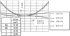
도 22a 및 도 22b는 도 21에 대응하는 커플링 렌즈와 대물 렌즈를 사용한 도 19의 광학계에서의 대물 렌즈 시프트량과 수차량의 측정 결과를 나타낸 그래프이다.22A and 22B are graphs showing measurement results of an objective lens shift amount and aberration amount in the optical system of FIG. 19 using a coupling lens and an objective lens corresponding to FIG. 21.
도 23은 도 19의 커플링 렌즈와 대물 렌즈의 면 형상을 특정하는 변수의 다른 예를 나타낸 도면이다.FIG. 23 is a diagram illustrating another example of variables that specify the plane shapes of the coupling lens and the objective lens of FIG. 19.
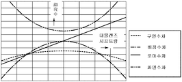
도 24a 및 도 24b는 도 23에 대응하는 커플링 렌즈와 대물 렌즈를 사용한 도 19의 광학계에서의 대물 렌즈 시프트량과 수차량의 측정 결과를 나타낸 그래프이다.24A and 24B are graphs showing measurement results of the objective lens shift amount and the aberration amount in the optical system of FIG. 19 using the coupling lens and the objective lens corresponding to FIG. 23.
관련출원의 상호 참조Cross Reference of Related Applications
본 명세서는 2005년 11월 22일자로 일본 특허청에 출원된 일본 특허출원 제2005-337137호와 관련된 내용을 포함하며, 상기 출원의 내용 전부는 참조에 의해 본 명세서에 통합된다. This specification includes content related to Japanese Patent Application No. 2005-337137 filed with the Japan Patent Office on November 22, 2005, the entire contents of which are incorporated herein by reference.
본 발명은 광 픽업 장치 및 광 디스크 장치에 관한 것이며, 특히 소형의 장치로 안정된 수차의 보정을 수행할 수 있도록 하는 광 픽업 장치 및 광 디스크 장치에 관한 것이다.BACKGROUND OF THE
최근, DVD(Digital Versatile Disc) 레코더/플레이어 등으로 대표되는 광 디스크 장치에서는, 랩탑 개인용 컴퓨터, 모바일 DVD 플레이어 등의 모바일 기기에의 대응과, 공간절약의 요구 등에 의해, 더욱더 소형화와 박형화가 요구되어 왔다. 또, 모바일 게임기 등에 있어서도, UMD(Universal Media Disc) 등의 고밀도 디스크의 재생이 가능하고, 또한 소형이면서 박형으로 제조될 수 있는 광 디스크 장치가 요구되어 왔다. 또, Blu-ray 디스크(상표)로 대표되는 고밀도 차세대 광 기록 매체를 사용하는 장치에서도, 고기능화, 디자인성 향상 등을 실현하기 위해, 소형화, 박형화는 피해할 수 없다.Background Art In recent years, in an optical disc device represented by a DVD (Digital Versatile Disc) recorder / player or the like, further miniaturization and thinning are required due to correspondence with mobile devices such as laptop personal computers, mobile DVD players, and the need for space saving. come. Moreover, also in a mobile game machine etc., the optical disc apparatus which can reproduce high density discs, such as UMD (Universal Media Disc), and can be manufactured small and thin is desired. In addition, even in the apparatus using a high density next-generation optical recording medium represented by a Blu-ray disc (trademark), miniaturization and thinning cannot be avoided in order to realize high functionality, improved design, and the like.
이러한 더욱 소형, 박형의 광 디스크 장치를 실현하기 위해, 광 디스크 장치에 사용되는 광 픽업과 그 광학계의 소형화, 박형화가 요구된다.In order to realize such a more compact and thin optical disk device, it is required to reduce the size and thickness of the optical pickup used in the optical disk device and its optical system.
종래, CD(Compact Disc), MD(Mini Disc) 등, NA가 그다지 높지 않은(즉, 고 기억 용량을 필요로 하지 않는) 기록 매체를 사용하는 광 디스크 장치에서는, 도 1에 나타낸 바와 같은 이른바 무한 광학계를 채용한 광 픽업을, 도 2에 나타낸 바와 같은 이른바 유한 광학계를 채용한 픽업으로 변경함으로써 장치의 소형화 및 박형화를 달성하였다(예를 들면, 일본 특허공개공보(발명자: KOKAI) 제2004-247034호 참조).Conventionally, in an optical disc apparatus using a recording medium having a small NA (ie, a high storage capacity), such as a CD (Compact Disc), MD (Mini Disc), or the like, the so-called infiniteness as shown in FIG. The optical pickup using the optical system was changed to the pickup employing the so-called finite optical system as shown in Fig. 2 to achieve miniaturization and thinning of the device (for example, Japanese Patent Laid-Open (KOKAI) No. 2004-247034). Reference).
무한 광학계에서, 광원(11)으로부터 조사된 광은 콜리메이터 렌즈(collimator lense)(12)를 통하여 평행 광으로 변화되고, 대물 렌즈(13)를 통과함으로써 기록 매체(14)의 기록면에 집광된다.In the infinite optical system, the light irradiated from the
무한 광학계는 트래킹 서보나 포커싱 서보에 대응하는 대물 렌즈(13)의 시프 트에 대해서 수차가 발생하지 않도록 구성되어 있다. 그러나, 무한 광학계에서는, 광원(11)으로부터 콜리메이터 렌즈(12)까지의 거리가 콜리메이터 렌즈(12)의 초점 거리와 거의 같은 정도일 것을 필요로 하고, 대물 렌즈(13)의 이동 범위를 충분히 충족시키는 굵은 평행광속을 얻을 수 있도록, 콜리메이터 렌즈(12)의 외경 치수와 광속 직경이 클 것을 필요로 하는데, 이것은 광학계 전체의 소형화 및 박형화를 제한한다.The infinite optical system is configured so that aberration does not occur with respect to the shift of the
이에 대해, 유한 광학계에서는, 대물 렌즈(13)으로부터 유한의 거리에 배치된 광원(11)으로부터 조사되는 광을 대물 렌즈(13)로 직접 수광하거나, 또는 커플링 렌즈(15)를 통해 대물 렌즈(13)로 수광하여, 기록 매체(14)의 기록면 상에 집광시킨다.In contrast, in the finite optical system, light irradiated from the
유한 광학계에서는, 대물 렌즈(13) 이외의 렌즈를 사용할 수 없거나, 렌즈 외경이 비교적 작은 커플링 렌즈(15)를 사용할 수 있고, 또 물체(object)와 상(image) 사이의 거리가 짧을 수 있으므로, 광학계 전체의 소형화 및 박형화가 가능해진다. 단, 트래킹 서보나 포커싱 서보를 위한 대물 렌즈(13)의 시프트에 대한 수차가 발생하지만, NA가 낮은 CD나 MD에서는, 대물 렌즈의 시프트에 의해 발생하는 수차량은 시스템 마진(system margin)이 붕괴될 정도로 크지 않기 때문에, 유한 광학계에 의한 소형화 및 박형화가 실현될 수 있었다.In the finite optical system, lenses other than the
그러나, NA가 큰 DVD나 UMD를 기록매체로서 사용하는 광 디스크 장치에 있어서, 장치를 소형화, 박형화하기 위해 유한 광학계를 채용은, 대물 렌즈의 시프트에 의해 발생하는 수차량이 시스템 마진을 붕괴할 정도로 악화시킬 가능성이 있어, 실용화가 곤란하였다. 또, 만일 실용화하였다고 해도, 수율의 악화나 시장 불량(market defect)의 증가 등을 유발할 가능성이 있었다..However, in an optical disk device using a DVD or UMD having a large NA as a recording medium, employing a finite optical system to reduce the size and thickness of the device is such that the amount of aberration generated by the shift of the objective lens collapses the system margin. There was a possibility of deterioration, and practical use was difficult. Moreover, even if it was put to practical use, there was a possibility of causing a deterioration in yield or an increase in market defects.
본 발명은 이와 같은 상황을 감안하여 이루어진 것이며, 소형의 장치로 안정된 수차의 보정을 실현하는 것이다.This invention is made | formed in view of such a situation, and implement | achieves the correction of stable aberration with a compact apparatus.
본 발명의 제1 실시예는, 광 기록 매체에 조사하는 광을 생성하는 광원과, 상기 광원으로부터 조사된 광을 상기 기록 매체의 기록면에 집광하는 대물 렌즈를 포함하는 광 픽업 장치이다. 상기 광 픽업 장치는 상기 광원과 상기 대물 렌즈 사이의 광로 상에 배치된 커플링 렌즈를 더 포함한다. 상기 광 픽업 장치에서, 상기 대물 렌즈가 시프트했을 때, 상기 대물 렌즈의 시프트량에 대응하여 정해진 위치이고, 상기 광원으로부터 조사된 광이 상기 커플링 렌즈를 통과하는 위치에서, 상기 광원으로부터 조사된 광에 미리 설정된 구면 수차량이 생기도록, 상기 커플링 렌즈의 면 형상이 형성되어 있다.A first embodiment of the present invention is an optical pickup apparatus including a light source for generating light irradiated to an optical recording medium and an objective lens for condensing light emitted from the light source onto a recording surface of the recording medium. The optical pickup apparatus further includes a coupling lens disposed on an optical path between the light source and the objective lens. In the optical pickup device, when the objective lens is shifted, the light is irradiated from the light source at a position determined according to the shift amount of the objective lens, and at a position where the light irradiated from the light source passes through the coupling lens. The surface shape of the coupling lens is formed so that a predetermined amount of spherical aberration occurs.
상기 커플링 렌즈를 통과하는 광에, 미리 설정된 4차 또는 6차 구면 수차량이 부가될 수 있다.A predetermined fourth or sixth spherical aberration amount may be added to the light passing through the coupling lens.
상기 커플링 렌즈는 구면 수차를 상기 커플링 렌즈를 통과하는 광에 부가하는 면 형상을 가질 수 있고, 상기 구면 수차는 식The coupling lens may have a surface shape that adds spherical aberration to light passing through the coupling lens, and the spherical aberration is
![]()
![]()
을 충족시키며, Satisfying
위 식에서, 상기 커플링 렌즈의 전체 유효 직경 영역에서, Sa는 Zernike 4차 구면 수차의 수차 계수이고, γ는 상기 커플링 렌즈의 전체 유효 직경 A에 대한 광속 직경 B의 비 B/A이며, δ는 광속 반경 B/2에 대한 대물 렌즈 시프트 시의 광속 이동량 s의 비 2s/B이고, Was는 대물 렌즈에 발생된 축외(off-axis) 비점 수차의 Zernike 비점 수차 계수이다. In the above formula, in the entire effective diameter region of the coupling lens, S a is the aberration coefficient of the Zernike quaternary spherical aberration, γ is the ratio B / A of the beam diameter B to the total effective diameter A of the coupling lens, δ is the ratio 2s / B of the light flux shift amount s at the objective lens shift with respect to the light beam radius B / 2, and W as is the Zernike astigmatism coefficient of the off-axis astigmatism generated in the objective lens.
상기 커플링 렌즈는 구면 수차를 상기 커플링 렌즈를 통과하는 광에 부가하는 면 형상을 가질 수 있고, 상기 구면 수차는 식The coupling lens may have a surface shape that adds spherical aberration to light passing through the coupling lens, and the spherical aberration is
![]()
![]()
및And
![]()
![]()
을 충족시키며,Satisfying
위 식에서, 상기 커플링 렌즈의 전체 유효 직경 영역에서, Sa는 Zernike 4차 구면 수차의 수차 계수이고, Sk는 Zernike 6차 구면 수차의 수차 계수이며, γ는 상기 커플링 렌즈의 전체 유효 직경 A에 대한 광속 직경 B의 비 B/A이며, δ는 광속 반경 B/2에 대한 대물 렌즈 시프트 시의 광속 이동량 s의 비 2s/B이고, Was는 대물 렌즈에 발생된 시야(fidld-of-view) 비점 수차의 Zernike 비점 수차 계수이다.In the above equation, in the entire effective diameter region of the coupling lens, S a is the aberration coefficient of Zernike fourth spherical aberration, S k is the aberration coefficient of Zernike sixth spherical aberration, and γ is the total effective diameter of the coupling lens The ratio B / A of the beam diameter B to A, δ is the ratio 2s / B of the amount of light movement s at the objective lens shift with respect to the beam radius B / 2, and W as is the field of view generated by the objective lens (fidld-of -view) Zernike astigmatism coefficients of astigmatism.
상기 대물 렌즈는 축외 코마 수차를 상기 대물 렌즈를 통과하는 광에 부가하는 면 형상을 가질 수 있고, 상기 축외 코마 수차는 식The objective lens may have a surface shape that adds off-axis coma aberration to light passing through the objective lens, and the off-axis coma aberration is
![]()
![]()
를 충족시키며,Satisfying
위 식에서, Wcoma는 상기 대물 렌즈를 통과하는 광의 시야 코마 수차의 Zernike 코마 수차 계수이고, 상기 커플링 렌즈의 전체 유효 직경 영역에서, Sa는 Zernike 4차 구면 수차의 수차 계수이며, γ는 상기 커플링 렌즈의 전체 유효 직경 A에 대한 광속 직경 B의 비 B/A이고, δ는 광속 반경 B/2에 대한 대물 렌즈 시프트 시의 광속 이동량 s의 비 2s/B이다.In the above equation, W coma is Zernike coma aberration coefficient of visual field coma aberration of light passing through the objective lens, and in the entire effective diameter region of the coupling lens, S a is aberration coefficient of Zernike fourth spherical aberration, and γ is The ratio B / A of the luminous flux diameter B to the total effective diameter A of the coupling lens, and δ is the ratio 2s / B of the luminous flux shift amount s at the objective lens shift with respect to the luminous flux radius B / 2.
상기 대물 렌즈는 구면 수차를 상기 대물 렌즈를 통과하는 광에 부가하는 면 형상을 가질 수 있고, 상기 구면 수차는 식The objective lens may have a surface shape that adds spherical aberration to light passing through the objective lens, and the spherical aberration is

을 충족시키며,Satisfying
위 식에서, Wsa는 대물 렌즈의 구면 수차의 Zernike 구면 수차 계수이고, 상기 커플링 렌즈의 전체 유효 직경 영역에서, Sa는 Zernike 4차 구면 수차의 수차 계수이고, Sk는 Zernike 6차 구면 수차의 수차 계수이며, γ는 상기 커플링 렌즈의 전체 유효 직경 A에 대한 광속 직경 B의 비 B/A이고, δ는 광속 반경 B/2에 대한 대물 렌즈 시프트 시의 광속 이동량 s의 비 2s/B이다.In the above equation, W sa is the Zernike spherical aberration coefficient of the spherical aberration of the objective lens, in the entire effective diameter region of the coupling lens, S a is the aberration coefficient of the Zernike fourth spherical aberration, and S k is the Zernike sixth spherical aberration Is a ratio B / A of the beam diameter B to the total effective diameter A of the coupling lens, and δ is the ratio 2s / B of the light flux shift amount s at the objective lens shift with respect to the beam radius B / 2. to be.
본 발명의 제1 실시예에서는, 광원과 대물 렌즈 사이의 광로 상에 커플링 렌즈가 배치되고, 상기 대물 렌즈가 시프트했을 때, 상기 대물 렌즈의 시프트량에 대응하여 정해진 위치이고, 상기 광원으로부터 조사된 광이 상기 커플링 렌즈를 통과하는 위치에서, 상기 광원으로부터 조사된 광에 미리 설정된 구면 수차량이 생기도록, 상기 커플링 렌즈의 면 형상이 형성되어 있다.In a first embodiment of the present invention, a coupling lens is disposed on an optical path between a light source and an objective lens, and when the objective lens is shifted, the coupling lens is positioned at a position corresponding to the shift amount of the objective lens and irradiated from the light source. The planar shape of the coupling lens is formed so that a predetermined amount of spherical aberration is generated in the light irradiated from the light source at a position where the passed light passes through the coupling lens.
본 발명의 제2 실시예는, 광 기록 매체에 조사하는 광을 생성하는 광원, 상기 광원으로부터 조사된 광을 상기 기록 매체의 기록면에 집광하는 대물 렌즈, 및 상기 광원과 상기 대물 렌즈 사이의 광로 상에 배치된 커플링 렌즈를 포함하는 광 픽업 장치이다. 상기 광 픽업 장치는 상기 커플링 렌즈와 상기 대물 렌즈 사이의 광로 상에 배치된 광학 소자를 더 포함한다. 상기 광 픽업 장치에서, 상기 대물 렌즈가 시프트했을 때, 상기 대물 렌즈의 시프트량에 대응하여 정해진 위치이고, 상기 광원으로부터 조사된 광이 상기 광학 소자를 통과하는 위치에서, 상기 광원으로부터 조사된 광에 미리 설정된 구면 수차량이 생기도록, 상기 광학 소자의 면 형상이 형성되어 있다. A second embodiment of the present invention provides a light source for generating light irradiated onto an optical recording medium, an objective lens for condensing light emitted from the light source onto a recording surface of the recording medium, and an optical path image between the light source and the objective lens. An optical pickup device comprising a coupling lens disposed in the. The optical pickup apparatus further includes an optical element disposed on an optical path between the coupling lens and the objective lens. In the optical pickup device, when the objective lens is shifted, the optical lens is positioned at a position corresponding to the shift amount of the objective lens, and at the position where the light irradiated from the light source passes through the optical element, the light irradiated from the light source. The surface shape of the said optical element is formed so that the preset spherical aberration amount may occur.
상기 광학 소자를 통과하는 광에, 미리 설정된 4차 또는 6차 구면 수차량이 부가될 수 있다. A preset fourth or sixth spherical aberration amount may be added to the light passing through the optical element.
상기 광학 소자는 광 디스크의 두께의 변동 또는 환경 온도 변동에 의해 발생하는 구면 수차를 보정하기 위해, 미리 광 디스크 장치에 배치되어 있는 다른 광학 소자와 일체로 구성될 수 있다.The optical element may be integrally formed with other optical elements which are arranged in advance in the optical disc apparatus in order to correct spherical aberration caused by variations in thickness of the optical disc or variations in environmental temperature.
상기 광학 소자는 액정 소자로 이루어질 수 있다.The optical element may be a liquid crystal element.
상기 광학 소자는 구면 수차를 상기 광학 소자를 통과하는 광에 부가하는 면 형상을 가질 수 있고, 상기 구면 수차는 식The optical element may have a surface shape that adds spherical aberration to light passing through the optical element, and the spherical aberration is
![]()
![]()
을 충족시키며,Satisfying
위 식에서, 상기 광학 소자의 전체 유효 직경 영역에서, Sa는 Zernike 4차 구면 수차의 수차 계수이고, γ는 상기 커플링 렌즈의 전체 유효 직경 A에 대한 광속 직경 B의 비 B/A이며, δ는 광속 반경 B/2에 대한 대물 렌즈 시프트 시의 광속 이동량 s의 비 2s/B이고, Was는 상기 대물 렌즈에 발생된 축외 비점 수차의 Zernike 비점 수차 계수이다.In the above formula, in the entire effective diameter region of the optical element, S a is the aberration coefficient of the Zernike quaternary spherical aberration, γ is the ratio B / A of the beam diameter B to the total effective diameter A of the coupling lens, δ Is a ratio 2s / B of the light beam shift amount s during the objective lens shift with respect to the light beam radius B / 2, and W as is a Zernike astigmatism coefficient of the off-axis astigmatism generated in the objective lens.
상기 광학 소자는 구면 수차를 상기 광학 소자를 통과하는 광에 부가하는 면 형상을 가질 수 있고, 상기 구면 수차는 식The optical element may have a surface shape that adds spherical aberration to light passing through the optical element, and the spherical aberration is
![]()
![]()
및And
![]()
![]()
을 충족시키며,Satisfying
위 식에서, 상기 광학 소자의 전체 유효 직경 영역에서, Sa는 Zernike 4차 구면 수차의 수차 계수이고, Sk는 Zernike 6차 구면 수차의 수차 계수이며, γ는 상기 커플링 렌즈의 전체 유효 직경 A에 대한 광속 직경 B의 비 B/A이며, δ는 광속 반경 B/2에 대한 대물 렌즈 시프트 시의 광속 이동량 s의 비 2s/B이고, Was는 상기 대물 렌즈에 발생된 시야 비점 수차의 Zernike 비점 수차 계수이다.In the above formula, in the entire effective diameter region of the optical element, S a is the aberration coefficient of Zernike fourth spherical aberration, S k is the aberration coefficient of Zernike sixth spherical aberration, γ is the total effective diameter A of the coupling lens Is the ratio B / A of the beam diameter B with respect to δ is the ratio 2s / B of the amount of light movement s during the objective lens shift with respect to the beam radius B / 2, and W as is Zernike of the visual astigmatism generated in the objective lens. Astigmatism coefficients.
상기 대물 렌즈는 축외 코마 수차를 상기 대물 렌즈를 통과하는 광에 부가하는 면 형상을 가질 수 있고, 상기 축외 코마 수차는 식The objective lens may have a surface shape that adds off-axis coma aberration to light passing through the objective lens, and the off-axis coma aberration is
![]()
![]()
를 충족시키며,Satisfying
위 식에서, Wcoma는 상기 대물 렌즈를 통과하는 광의 시야 코마 수차의 Zernike 코마 수차 계수이고, 상기 광학 소자의 전체 유효 직경 영역에서, Sa는 Zernike 4차 구면 수차의 수차 계수이며, γ는 상기 광학 소자의 전체 유효 직경 A에 대한 광속 직경 B의 비 B/A이다.In the above formula, W coma is Zernike coma aberration coefficient of visual field coma aberration of light passing through the objective lens, and in the entire effective diameter region of the optical element, S a is aberration coefficient of Zernike fourth spherical aberration, γ is the optical The ratio B / A of the beam diameter B to the total effective diameter A of the device.
상기 광학 소자는 구면 수차를 상기 대물 렌즈를 통과하는 광에 부가하는 면 형상을 가질 수 있고, 상기 구면 수차는 식The optical element may have a surface shape that adds spherical aberration to light passing through the objective lens, and the spherical aberration is

을 충족시키며,Satisfying
위 식에서, Wsa는 대물 렌즈의 구면 수차의 Zernike 구면 수차 계수이고, 상기 커플링 렌즈의 전체 유효 직경 영역에서, Sa는 Zernike 4차 구면 수차의 수차 계수이고, Sk는 Zernike 6차 구면 수차의 수차 계수이며, γ는 상기 커플링 렌즈의 전체 유효 직경 A에 대한 광속 직경 B의 비 B/A이고, δ는 광속 반경 B/2에 대한 대물 렌즈 시프트 시의 광속 이동량 s의 비 2s/B이다.In the above equation, W sa is the Zernike spherical aberration coefficient of the spherical aberration of the objective lens, in the entire effective diameter region of the coupling lens, S a is the aberration coefficient of the Zernike fourth spherical aberration, and S k is the Zernike sixth spherical aberration Is a ratio B / A of the beam diameter B to the total effective diameter A of the coupling lens, and δ is the ratio 2s / B of the light flux shift amount s at the objective lens shift with respect to the beam radius B / 2. to be.
본 발명의 제2 실시예에서는, 상기 커플링 렌즈와 상기 대물 렌즈 사이의 광로 상에 상기 광학 소자가 배치되어 있고, 상기 대물 렌즈가 시프트했을 때, 상기 대물 렌즈의 시프트량에 대응하여 정해진 위치이고, 상기 광원으로부터 조사된 광이 상기 광학 소자를 통과하는 위치에서, 상기 광원으로부터 조사된 광에 미리 설정된 구면 수차량이 생기도록, 상기 광학 소자의 면 형상이 형성되어 있다.In a second embodiment of the present invention, the optical element is disposed on an optical path between the coupling lens and the objective lens, and when the objective lens is shifted, the optical element is positioned at a position corresponding to the shift amount of the objective lens. The planar shape of the optical element is formed such that a predetermined amount of spherical aberration occurs in the light irradiated from the light source at a position where the light irradiated from the light source passes through the optical element.
본 발명의 제3 실시예는, 광 기록 매체에 조사하는 광을 생성하는 광원과, 상기 광원으로부터 조사된 광을 상기 기록 매체의 기록면에 집광하는 대물 렌즈를 포함하는 광 픽업 유닛을 가지는 광 디스크 장치이다. 상기 광 디스크 장치는, 상기 광원과 상기 대물 렌즈 사이의 광로 상에 배치된 커플링 렌즈를 더 포함한다. 상기 광 디스크 장치에서, 상기 대물 렌즈가 시프트했을 때, 상기 대물 렌즈의 시프트량에 대응하여 정해진 위치이고, 상기 광원으로부터 조사된 광이 상기 커플링 렌즈를 통과하는 위치에서, 상기 광원으로부터 조사된 광에 미리 설정된 구면 수차량이 생기도록, 상기 커플링 렌즈의 면 형상이 형성되어 있다.A third embodiment of the present invention is an optical disk apparatus having a light pickup unit including a light source for generating light irradiated to an optical recording medium and an objective lens for condensing light emitted from the light source onto a recording surface of the recording medium. to be. The optical disk apparatus further includes a coupling lens disposed on an optical path between the light source and the objective lens. In the optical disk device, when the objective lens is shifted, the light is irradiated from the light source at a position determined according to the shift amount of the objective lens, and at the position where the light irradiated from the light source passes through the coupling lens. The surface shape of the coupling lens is formed so that a predetermined amount of spherical aberration occurs.
본 발명의 제3 실시예에서는, 상기 광원과 상기 대물 렌즈 사이의 광로 상에 상기 커플링 렌즈가 배치되어 있고, 상기 대물 렌즈가 시프트했을 때, 상기 대물 렌즈의 시프트량에 대응하여 정해진 위치이고, 상기 광원으로부터 조사된 광이 상기 커플링 렌즈를 통과하는 위치에서, 상기 광원으로부터 조사된 광에 미리 설정된 구면 수차량이 생기도록, 상기 커플링 렌즈의 면 형상이 형성되어 있다.In a third embodiment of the present invention, the coupling lens is disposed on an optical path between the light source and the objective lens, and when the objective lens is shifted, the coupling lens is positioned at a position corresponding to the shift amount of the objective lens, The surface shape of the coupling lens is formed such that a predetermined amount of spherical aberration occurs in the light irradiated from the light source at a position where the light irradiated from the light source passes through the coupling lens.
본 발명의 제4 실시예는, 광 기록 매체에 조사하는 광을 생성하는 광원, 상기 광원으로부터 조사된 광을 상기 기록 매체의 기록면에 집광하는 대물 렌즈, 및 상기 광원과 상기 대물 렌즈 사이의 광로 상에 배치된 커플링 렌즈를 포함하는 광 픽업 유닛을 가지는 광 디스크 장치이다. 상기 광 디스크 장치는, 상기 커플링 렌즈와 상기 대물 렌즈 사이의 광로 상에 배치된 광학 소자를 더 포함한다. 상기 광 디스크 장치에서, 상기 대물 렌즈가 시프트했을 때, 상기 대물 렌즈의 시프트량에 대응하여 정해진 위치이고, 상기 광원으로부터 조사된 광이 상기 광학 소자를 통과하는 위치에서, 상기 광원으로부터 조사된 광에 미리 설정된 구면 수차량이 생기도록, 상기 광학 소자의 면 형상이 형성되어 있다.A fourth embodiment of the present invention provides a light source for generating light irradiated onto an optical recording medium, an objective lens for condensing light emitted from the light source on a recording surface of the recording medium, and an optical path image between the light source and the objective lens. An optical disk apparatus having an optical pickup unit including a coupling lens disposed in the. The optical disk apparatus further includes an optical element disposed on an optical path between the coupling lens and the objective lens. In the optical disk apparatus, when the objective lens is shifted, it is a position corresponding to the shift amount of the objective lens, and at the position where the light irradiated from the light source passes through the optical element, the light is irradiated from the light source. The surface shape of the said optical element is formed so that the preset spherical aberration amount may occur.
본 발명의 제4 실시예에서는, 상기 커플링 렌즈와 상기 대물 렌즈 사이의 광로 상에 광학 소자가 배치되어 있고, 상기 대물 렌즈가 시프트했을 때, 상기 대물 렌즈의 시프트량에 대응하여 정해진 위치이고, 상기 광원으로부터 조사된 광이 상기 광학 소자를 통과하는 위치에서, 상기 광원으로부터 조사된 광에 미리 설정된 구면 수차량이 생기도록, 상기 광학 소자의 면 형상이 형성되어 있다.In a fourth embodiment of the present invention, an optical element is disposed on an optical path between the coupling lens and the objective lens, and when the objective lens is shifted, it is a position determined corresponding to the shift amount of the objective lens, The planar shape of the said optical element is formed so that the predetermined spherical aberration amount may generate | occur | produce in the light irradiated from the said light source in the position which the light irradiated from the said light source passes through the said optical element.
이하, 본 발명의 실시예에 대해 설명한다. 본 발명의 구성요건과 명세서 또는 도면에 기재된 실시예 사이의 대응 관계를 예시하면 이하에 설명하는 바와 같다. 이 기재는 본 발명을 지지하는 실시예가 명세서 또는 도면에 기재되어 있음을 확인하기 위한 것이다. 따라서, 명세서 또는 도면에는 기재되어 있지만, 본 발명의 구성 요건에 대응하는 실시예로서, 여기에 기재되어 있지 않은 실시예가 있더라도, 그것은 그 실시예가 그 구성요건에 대응하는 것이 아님을 의미하는 것은 아니다. 반대로, 어떤 실시예가 구성요건에 대응하는 것으로서 기재되어 있더라도, 그것은 그 실시예가 그 구성요건 이외의 어떤 구성요건에 대응하지 않는 것임을 의미하는 것은 아니다.EMBODIMENT OF THE INVENTION Hereinafter, the Example of this invention is described. The correspondence between the configuration requirements of the present invention and the embodiments described in the specification or drawings is as described below. This description is intended to confirm that the embodiments supporting the present invention are described in the specification or drawings. Accordingly, although described in the specification or the drawings, there may be embodiments corresponding to the constituent requirements of the present invention, even though the embodiments are not described herein, it does not mean that the embodiments do not correspond to the constituent requirements. On the contrary, even if an embodiment is described as corresponding to a configuration requirement, it does not mean that the embodiment does not correspond to any configuration requirement other than the configuration requirement.
본 발명의 제1 실시예의 광 픽업 장치는, 광 기록 매체[예를 들면, 도 4의 광 기록 매체(204)]에 조사하는 광을 생성하는 광원[예를 들면, 도 4의 광원(201)]과, 상기 광원으로부터 조사된 광을 상기 기록 매체의 기록면에 집광하는 대물 렌즈[예를 들면, 도 4의 대물 렌즈(203)]를 포함하는 광 픽업 장치이다. 상기 광 픽업장치는, 상기 광원과 상기 대물 렌즈 사이의 광로 상에 배치된 커플링 렌즈[예를 들면, 도 4의 커플링 렌즈(205)]를 더 포함한다. 상기 커플링 렌즈의 면 형상은, 상기 대물 렌즈가 시프트했을 때, 상기 대물 렌즈의 시프트량에 대응하여 정해진 위치이고, 상기 광원으로부터 조사된 광이 상기 커플링 렌즈를 통과하는 위치에서, 상기 광원으로부터 조사된 광에 미리 설정된 구면 수차량이 생기도록, 형성되어 있다.The optical pickup apparatus of the first embodiment of the present invention is a light source (for example, the
본 발명의 제2 실시예의 광 픽업 장치는, 광 기록 매체[예를 들면, 도 8의 광 기록 매체(204)]에 조사하는 광을 생성하는 광원[예를 들면, 도 8의 광원(201)], 상기 광원으로부터 조사된 광을 상기 기록 매체의 기록면에 집광하는 대물 렌즈[예를 들면, 도 8의 대물 렌즈(203)], 및 상기 광원과 상기 대물 렌즈 사이 의 광로 상에 배치된 커플링 렌즈[예를 들면, 도 8의 커플링 렌즈(205)]를 포함한다. 상기 광 픽업 장치는, 상기 커플링 렌즈와 상기 대물 렌즈 사이의 광로 상에 배치된 광학 소자[예를 들면, 도 8의 광학 소자(206)]를 더 포함한다. 상기 광학 소자의 면 형상은, 상기 대물 렌즈가 시프트했을 때, 상기 대물 렌즈의 시프트량에 대응하여 정해진 위치이고, 상기 광원으로부터 조사된 광이 상기 광학 소자를 통과하는 위치에서, 상기 광원으로부터 조사된 광에 미리 설정된 구면 수차량이 생기도록, 형성되어 있다. 이 광 픽업 장치에서, 상기 광학 소자는 광 디스크의 두께의 변동 또는 환경 온도 변동에 의해 발생하는 구면 수차를 보정하기 위해, 미리 광 디스크 장치에 배치되어 있는 다른 광학 소자와 일체로 구성될 수 있다.The optical pickup apparatus of the second embodiment of the present invention is a light source (for example, the
본 발명의 제3 실시예의 광 디스크 장치는, 광 기록 매체[예를 들면, 도 4의 광 기록 매체(204)]에 조사하는 광을 생성하는 광원[예를 들면, 도 4의 광원(201)]과 상기 광원으로부터 조사된 광을 상기 기록 매체의 기록면에 집광하는 대물 렌즈[예를 들면, 도 4의 대물 렌즈(203)]를 구비하는 광 픽업 유닛[예를 들면, 도 3의 광 픽업 유닛(101)]을 가지는 광 디스크 장치이다. 상기 광 디스크 장치는 상기 광원과 상기 대물 렌즈 사이의 광로 상에 배치된 커플링 렌즈[예를 들면, 도 4의 커플링 렌즈(205)]를 더 포함한다. 상기 광 디스크 장치에서는, 상기 대물 렌즈가 시프트했을 때, 상기 대물 렌즈의 시프트량에 대응하여 정해진 위치이고, 상기 광원으로부터 조사된 광이 상기 커플링 렌즈를 통과하는 위치에서, 상기 광원으로부터 조사된 광에 미리 설정된 구면 수차량이 생기도록, 상기 커플링 렌즈의 면 형상이 형성되어 있다.The optical disk apparatus of the third embodiment of the present invention is a light source (for example, the
본 발명의 제4 실시예의 광 디스크 장치는, 광 기록 매체[예를 들면, 도 8의 광 기록 매체(204)]에 조사하는 광을 생성하는 광원[예를 들면, 도 8의 광원(201)], 상기 광원으로부터 조사된 광을 상기 기록 매체의 기록면에 집광하는 대물 렌즈[예를 들면, 도 8의 대물 렌즈(203)], 및 상기 광원과 상기 대물 렌즈 사이의 광로 상에 배치된 커플링 렌즈[예를 들면, 도 8의 커플링 렌즈(205)]를 포함하는 광 픽업 유닛[예를 들면, 도 3의 광 픽업 유닛(101)]을 가지는 광 디스크 장치이다. 상기 광 디스크 장치는, 상기 커플링 렌즈와 상기 대물 렌즈 사이의 광로 상에 배치된 광학 소자[예를 들면, 도 8의 광학 소자(206)]를 더 포함한다. 상기 광 디스크 장치에서는, 상기 대물 렌즈가 시프트했을 때, 상기 대물 렌즈의 시프트량에 대응하여 정해진 위치이고, 상기 광원으로부터 조사된 광이 상기 광학 소자를 통과하는 위치에서, 상기 광원으로부터 조사된 광에 미리 설정된 구면 수차량이 생기도록, 상기 광학 소자의 면 형상이 형성되어 있다.The optical disk apparatus of the fourth embodiment of the present invention is a light source (for example, the
이하, 도면을 참조하여 본 발명의 실시예를 설명한다.Hereinafter, embodiments of the present invention will be described with reference to the drawings.
도 3은 본 발명을 적용한 광 디스크 장치의 일 실시예에 따른 구성예를 나타낸 블록도이다.3 is a block diagram showing a configuration example according to an embodiment of the optical disk apparatus to which the present invention is applied.
도면에 나타낸 바와 같이, 본 실시예에 따르면, 광 픽업 유닛(101)은 내장된 광원, 예를 들면 레이저 다이오드로부터 광을 생성하고, 후술하는 소정의 광학계를 통하여 광 디스크(151) 상에 집광하며, 그 반사광을 복수의 수광 유닛을 가지는 광 검출 유닛으로 검출하고, 각 수광 유닛의 출력 신호를 PD 출력 신호로서 연산 회로(102)에 출력하도록 되어 있다.As shown in the figure, according to this embodiment, the
연산 회로(102)는 광 디스크 재생용의 데이터 검출 신호(RF 신호), 광축 방향에서의 레이저광의 포커스의 변위(displacement)를 나타낸 포커스 에러 신호, 및 광 디스크의 반경 방향에서의 트래킹의 변위를 나타낸 트래킹 에러 신호를 계산하여, 데이터 검출 신호를 재생 회로(103)에 출력하고, 포커스 에러 신호 및 트래킹 에러 신호를 제어 회로(104)에 출력한다.The
재생 회로(103)는 연산 회로(102)로부터 공급된 데이터 검출 신호를 등화(equalize)한 다음, 2치화하고, 또한 에러 정정하면서 복조한 신호를, 재생 신호로서 소정의 장치에 출력한다.The
제어 회로(104)는 연산 회로(102)로부터 공급된 포커스 에러 신호에 따라, 포커스 서보 액추에이터(106)를 제어하여, 예를 들면 광 픽업 유닛(101)의 대물 렌즈를 광축 방향으로 이동시켜 포커스를 조정하하고, 연산 회로(102)로부터 공급된 트래킹 에러 신호에 따라, 트래킹 서보 액추에이터(107)를 제어하여, 예를 들면 광 픽업 유닛(101)을 광 디스크(151)의 반경 방향으로 이동시켜 트래킹을 조정한다. 포커스 서보 액추에이터(106)와 트래킹 서보 액추에이터(107)는 실제로 하나의 액추에이터로서 구성되며, 후술하는 대물 렌즈는 이 액추에이터에 탑재되어 있다.The
또한, 제어 회로(104)는 모터(109)를 제어하여, 광 디스크(151)을 소정의 속도 회전시킨다.In addition, the
제어 회로(104)는, 입력 장치(105)로부터 사용자에 의한 조작에 대응하는 신호를 받고, 그 신호에 따라 각 회로를 제어한다.The
광 픽업 유닛(101)은, 이른바 유한 광학계를 채용한 광 픽업 장치로서 구성 되며, 예를 들면 도 4에 나타낸 바와 같이 구성되어 있다. 동 도면에서, 광 픽업 장치(200)는 광 픽업 유닛(101)의 일 실시예의 구성예이고, 이른바 유한 광학계를 채용한 광 픽업 장치로서, 광원(201)으로부터 조사된 광을 소정 각도의 광속(light flux)으로 변환하는 커플링 렌즈(205)와, 커플링 렌즈(205)를 통과한 광을 기록 매체(204)의 기록면 상에 집광시키는 대물 렌즈(203)를 가지는 것이다. 기록 매체(204)는 도 3의 광 디스크(151)를 간소화한 형태이고, 기록 매체(204)와 광 디스크(151)는 실질적으로 같은 것이다.The
대물 렌즈(203)는 정현 조건(sine condition)을 충족시키도록 설계되어 있고, 대물 렌즈(203)를 통과한 광에서 축외 수차로서의 구면 수차와 코마 수차가 발생하지 않도록 구성되어 있지만, 비점수차는 발생된다.Although the
커플링 렌즈(205)의 면 형상이, 커플링 렌즈(205)를 통과하는 광에서 수차가 발생하지 않도록 설계되어 있는 경우, 예를 들면, 트래킹 서보를 행하기 위한 대물 렌즈(203)의 이동 또는 시프트는, 이른바 대물렌즈 시프트를 유발시키고, 대물 렌즈(203)에 의한 비점 수차량은, 대물 렌즈의 시프트량의 2차 함수가 된다. 따라서, 대물 렌즈(203)의 시프트량이 커질수록 유한 광학계를 채용한 광 픽업 장치에서 비점 수차의 영향이 더 커진다.When the surface shape of the
도 5는, 도 4의 광 픽업 장치(200)에서 대물렌즈 시프트가 발생한 경우의 예를 나타낸 도면이다. 동 도면에서, 도 4의 경우와 비교하면, 대물 렌즈(203)가 광축에 수직하는 방향으로 이동한다.FIG. 5 is a diagram illustrating an example in which an objective lens shift occurs in the
전술한 대물 렌즈의 시프트에 의해 발생하는 수차량은, 예를 들면 NA가 낮은 CD(Compact Disc)와 MD(Mini Disc) 등의 광 기록 매체에 대한 정보의 기록 또는 재생 등을 수행하는 경우, 시스템 마진이 붕괴될 정도로 크지 않기 때문에, 그 정도의 수차는 허용할 수 있다. 하지만, NA가 큰 DVD(Digital Versatile Disc)와 UMD(Universal Media Disc) 등의 광 기록 매체에 대한 정보의 기록 또는 재생 등을 수행하는 경우, 그 수차는 무시할 수 없는 영향력을 가질 우려가 있다.The amount of aberration caused by the shift of the objective lens described above is, for example, a system when recording or reproducing information on an optical recording medium such as CD (Compact Disc) and MD (Mini Disc) having a low NA. Since the margin is not large enough to collapse, that much aberration is acceptable. However, when recording or reproducing information on an optical recording medium such as a DVD having a large NA (Digital Versatile Disc) and a UMD (Universal Media Disc), the aberration may have a negligible influence.
그러므로, 본 발명에 따르면, 전술한 대물 렌즈(203)의 시프트에 따라 발생하는 수차를 보정하기 위해, 커플링 렌즈(205)의 특성을, 예를 들면 렌즈의 면 형상을 소정의 형상으로 설계함으로써 변경한다.Therefore, according to the present invention, in order to correct the aberration caused by the shift of the
대물 렌즈 시프트가 발생하고 있는 경우, 광원(201)으로부터 조사된 광빔의 커플링 렌즈(205) 내의 통과 위치가 상이하다.When the objective lens shift is occurring, the passing position in the
예를 들면, 대물 렌즈 시프트가 발생하고 있지 않은 도 4에 나타낸 바와 같은 상태에서, 광원(201)으로부터 조사된 광빔의 커플링 렌즈(205) 내의 통과 위치는 도 6에 나타낸 바와 같다. 도 6은 커플링 렌즈(205)를, 광원(201)으로부터 조사되는 광빔의 광축 상의 한점에서 본 도면이다. 이 도면에서, 커플링 렌즈(205)의 직경과 거의 같은 커플링 렌즈(205)의 전체 유효 영역 내에서, 광원(201)으로부터 조사되는 광빔의 광속이 통과하는 광속 직경 영역(221)은 중심 부분에 전체 유효 영역과 동심원형으로 배치되어 있다.For example, in the state as shown in FIG. 4 in which the objective lens shift has not occurred, the passing position in the
한편, 대물 렌즈 시프트가 발생하고 있는 도 5에 나타낸 바와 같은 상태에 서, 광원(201)으로부터 조사된 광빔의 커플링 렌즈(205) 내의 통과 위치는 도 7에 나타낸 바와 같다. 도 7은 도 6과 마찬가지로, 커플링 렌즈(205)를 광원(201)으로 부터 조사되는 광빔의 광축 상의 한점에서 본 도면이다. 이 도면에서, 커플링 렌즈(205)의 전체 유효 영역 내에서, 광원(201)으로부터 조사되는 광빔의 광속이 통과하는 광속 직경 영역(221)은, 도 6의 경우와 비교하여, 도면 중 상 방향으로 변위된 위치에 배치되어 있다.On the other hand, in the state as shown in FIG. 5 where the objective lens shift is occurring, the passing position in the
따라서, 대물 렌즈(203)의 렌즈 시프트량에 따라, 광원(201)으로부터 조사된 광빔의 커플링 렌즈(205) 내의 통과 위치가 달라지므로, 미리 커플링 렌즈(205) 내의 통과 위치에 따라 렌즈의 면 형상을 소정의 비율로 변화시키는 등에 의해 최적화하면, 대물 렌즈(203)의 시프트에 따라 발생하는 수차를 커플링 렌즈(205)의 특성에 의해 보정하는 것이 가능해진다.Therefore, since the passing position in the
커플링 렌즈(205)의 전체 유효 직경의 파면 수차의 Zernike 다항식 전개에 의한 해석으로부터, 다음과 같이 관계식을 도출할 수 있다. 커플링 렌즈(205)의 전체 유효 직경 영역에 부가하는 구면 수차의 Zernike 4차 구면 수차의 수차 계수를 Sa, 커플링 렌즈의 전체 유효 직경 A에 대한 광속 직경 B의 비 B/A를 γ, 그리고 광속 반경 B/2에 대한 대물 렌즈 시프트 시의 광속 이동량 s의 비 2s/B를δ라고 하면, 커플링 렌즈에서 유래한, 비점 수차의 수차 계수 A 및 코마 수차의 수차 계수 C는 식 (1)로 나타낼 수 있다.From the analysis by Zernike polynomial expansion of the wavefront aberration of the whole effective diameter of the

위 식에서, γ = B/A 이고, δ = 2s/B 이다.In the above formula, γ = B / A and δ = 2s / B.
따라서, 커플링 렌즈(205)의 전체 유효 직경의 수차량으로서 적당한 4차 구 면 수차 Sa를 부여함으로써, 대물 렌즈 시프트 시에, 대물 렌즈의 시프트량의 2차 함수로 변화하는 임의의 비점 수차를 커플링 렌즈(205)에 의해 발생시킬 수 있다.Therefore, by providing an appropriate fourth-order spherical aberration S a as the aberration amount of the entire effective diameter of the
다시 말해, 대물 렌즈(203)에 의해 발생된 비점 수차, 즉 축외 비점 수차의 Zernike 비점 수차 계수를 Was라고 하면, 식 (2)를 충족시키는 4차 구면 수차 Sa를 부여하도록 커플링 렌즈(205)의 면 형상이 최적화되고, 이는 대물 렌즈 시프트가 발생하여도 비점 수차가 적은 시야 특성이 개선된 광 픽업 장치의 구성을 가능하게 한다.In other words, assuming that the aberration aberration generated by the
![]()
![]()
이렇게 함으로써, 유한 광학계를 채용한 광 픽업을 구성하여, 장치를 소형화, 박형화할 수 있다. 또, 대물 렌즈 시프트에 수반하는 수차의 발생이 억제될 수 있어, 예를 들면, NA가 큰 DVD와 UMD 같은 광 기록 매체에 대한 정보의 기록 또는 재생 시에도, 안정된 동작을 실현할 수 있다.In this way, an optical pickup employing a finite optical system can be configured to reduce the size and thickness of the device. In addition, generation of aberration accompanying the objective lens shift can be suppressed, so that stable operation can be realized even when recording or reproducing information on optical recording media such as DVD and UMD having a large NA.
이상에서는, 적당한 Zernike 4차 구면 수차의 수차 계수 Sa를 구함으로써, 대물 렌즈(203)의 시프트에 의해 발생하는 비점수차를 보정하는 경우에 대하여 기술하였다. 이 경우에, 전술한 식 (1)에서의 코마 수차 계수 C도 또한 Zernike 4차 구면 수차의 수차 계수 Sa의 함수이므로, γ와δ와 같은 광학 파라미터의 일정한 값이 대물 렌즈(203)의 시프트에 의해 발생하는 비점수차를 보정하더라도, 코마 수차량이 증가할 가능성이 있다.In the above, the case where the astigmatism caused by the shift of the
따라서, 비점 수차의 보정에 따라 발생할 수 있는 코마 수차도 또한 보정되는 경우, 다음과 같은 방식으로 커플링 렌즈(205)의 면 형상을 최적화할 수 있다.Therefore, when the coma aberration that may occur due to the correction of the astigmatism is also corrected, the surface shape of the
커플링 렌즈(205)의 전체 유효 직경 영역에 부가하는 구면 수차의 Zernike 4차 구면 수차의 수차 계수를 Sa, Zernike 6차 구면 수차의 수차 계수를 Sk, 커플링 렌즈의 전체 유효 직경 A에 대한 광속 직경 B의 비 B/A를 γ, 그리고 광속 반경 B/2에 대한 대물 렌즈 시프트 시의 광속 이동량 s의 비 2s/B를δ라고 하면, 커플링 렌즈(205)에서 유래한, 비점 수차의 수차 계수 A 및 코마 수차의 수차 계수 C는 식 (3)으로 나타낼 수 있다.The aberration coefficient of Zernike 4th spherical aberration of spherical aberration added to the entire effective diameter region of

위 식에서, γ = B/A 이고, δ = 2s/B 이다.In the above formula, γ = B / A and δ = 2s / B.
따라서, 커플링 렌즈(205)의 전체 유효 직경의 수차량으로서 적당한 4차 구면 수차 Sa 와 6차 구면 수차 Sk를 부여함으로써, 대물 렌즈 시프트 시에, 적당한 코마 수차와 대물 렌즈의 시프트량의 2차 함수로 변화하는 임의의 비점 수차를 커플링 렌즈(205)에 의해 발생시킬 수 있다.Therefore, by providing the fourth order spherical aberration S a and the sixth order spherical aberration S k as appropriate aberration amounts of the entire effective diameters of the
대물 렌즈(203)에 발생된 시야 비점 수차(축외 비점 수차)의 Zernike 비점 수차 계수를 Was라고 하면, 식 (4)와 식 (5)를 동시에 충족시키는 4차 구면 수차 Sa와 6차 구면 수차 Sk를 부여하도록, 커플링 렌즈의 면 형상이 최적화되고, 이는 더욱 시야 특성이 개선된 광 픽업 장치의 구성을 가능하게 한다.If the Zernike astigmatism coefficient of the visual astigmatism (off-axis astigmatism) generated in the

이렇게 함으로써, 유한 광학계를 채용한 광 픽업을 구성하여, 장치를 소형화, 박형화할 수 있다. 또, 비점 수차의 보정에 따라 발생할 가능성이 있는 코마 수차가 또한 보정되고, 대물 렌즈 시프트에 수반하는 수차의 발생이 또한 억제될 수 있어, 예를 들면, NA가 큰 DVD, UMD 등의 광 기록 매체에 대한 정보의 기록 또는 재생 시에도, 안정된 동작을 실현할 수 있다.In this way, an optical pickup employing a finite optical system can be configured to reduce the size and thickness of the device. In addition, coma aberration likely to occur due to correction of astigmatism can also be corrected, and generation of aberration accompanying objective lens shift can also be suppressed, for example, an optical recording medium such as a DVD having a large NA, UMD, or the like. Even during recording or reproducing of the information, the stable operation can be realized.
이상에서는, 커플링 렌즈(205)의 전체 유효 직경에 대해, 적당한 4차 구면 수차 Sa 및 6차 구면 수차 Sk를 부여하도록, 커플링 렌즈(205)의 면 형상을 최적화하는 예에 대하여 설명하였으나, 커플링 렌즈(205)의 면 형상을 최적화하는 대신에, 예를 들면, 도 8에 나타낸 바와 같이, 적당한 구면 수차를 부가하기 위한 렌즈나 액정 소자와 같은 광학 소자를, 광 픽업 장치의 광로 중에 배치할 수도 있다.In the above, the example which optimizes the surface shape of the
도 8은 광 픽업 유닛(101)의 다른 구성예를 나타낸 블록도이다. 이 도면에 서, 도 4의 경우와는 다르게, 적당한 구면 수차를 부가하기 위한 광학 소자(206)가, 커플링 렌즈(205)와 대물 렌즈(203) 사이에 배치되어 있다. 또, 이 예에서, 커플링 렌즈(205)의 면 형상은, 전술한 식 (2), 식 (4), 및 식 (5) 등에 의해 특히 최적화되어 있지 않지만, 전체 유효 직경에 전체에 걸쳐 균일한 특성을 가지도록 구성되어 있다[종래의 커플링 렌즈와 동일한 것을 커플링 렌즈(205)로서 사용한다]. 그 외는 도 4의 경우와 동일이다.8 is a block diagram showing another configuration example of the
광학 소자(206)는, 예를 들면 도 9에 나타낸 바와 같이 구성된다. 도 9는 도 8의 광학 소자(206)를 광원(201)으로부터 조사되는 광의 광축 상의 한점에서 본 도이다. 이 도면에 나타낸 바와 같이, 광학 소자(206)는 통과하는 광의 광축의 중심, 즉 도면 중 세로 방향의 파선과 가로 방향의 파선이 교차하는 점으로부터의 거리 ρ에 따라 상이한 수차량을 발생시키도록 구성되어 있다.The
도 10은 광학 소자(206)에서 발생된 수차량의 특성의 예를 나타낸 도면이다. 이 도면에서, 세로축은 수차량을 나타내고, 가로축은 ρ의 값을 나타낸다. 예를 들면, 전술한 식 (2), 식 (4), 및 식 (5) 등에 의해 구해진 최적인 특성이 선(301)에 의해 부여되는 경우, 광학 소자(206)는 선(302)로 나타낸 바와 같은 특성을 가지도록 구성되고, 이는 선(301)에 의해 표현되는 특성을 근사할 수 있게 한다. 그 결과, 커플링 렌즈(205)의 면 형상을 최적화한 경우와 마찬가지로, 대물 렌즈 시프트에 의해 발생하는 수차를 보정할 수 있다.10 is a diagram showing an example of the characteristic of the amount of aberration generated in the
광학 소자(206)는 대물 렌즈(203)의 시프트에 따라 발생하는 비점 수차를 보정하기 위해서만 설치될 필요는 없고, 예를 들면 익스팬더 렌즈(expander lens)와 같은, 광 디스크의 두께의 변동, 환경 온도 변동 등에 의해 발생된 구면 수차를 보정하기 위해 미리 광 디스크 장치 등에 배치되어 있는 광학 소자로 구성될 수도 있다.The
또한, 광학 소자(206)는, 렌즈 등에 의해 구성되는 것에 한정되지 않고, 예를 들면 액정 소자로 구성될 수 있다. 이와 같이함으로써, 광학 소자(206)의 면 형상을 용이하게 조절할 수 있게 된다.In addition, the
이상에서는, 대물 렌즈(203)의 시프트에 따라 발생하는 수차를 커플링 렌즈(205) 또는 광학 소자(206)에 의해 보정하는 예에 대하여 설명하였으나, 수차를 대물 렌즈(203)에 의해 보정할 수도 있다. 이 경우, 통상, 정현 조건을 충족시키도록 설계되어 있는 대물 렌즈(203)의 면 형상을 의도적으로 변경하여, 대물 렌즈(203)를 통과하는 광에 적당한 축외 코마 수차를 부가할 수 있다.In the above, an example in which the aberration generated by the shift of the
더욱 구체적으로는, 대물 렌즈(203)의 축외 코마 수차의 Zernike 코마 수차 계수를 Wcoma, 커플링 렌즈(205)의 전체 유효 직경 영역에 부가하는 구면 수차의 Zernike 4차 구면 수차의 수차 계수를 Sa, 커플링 렌즈의 전체 유효 직경 A에 대한 광속 직경 B의 비 B/A를 γ, 그리고 광속 반경 B/2에 대한 대물 렌즈 시프트 시의 광속 이동량 s의 비 2s/B를δ라고 하면, 식 (6)을 충족시키는 코마 수차 계수를 부여하도록, 대물 렌즈의 면 형상을 최적화할 수 있다.More specifically, the Zernike coma aberration coefficient of the off-axis coma aberration of the
![]()
![]()
전술한 바와 같이 면 형상이 최적화된 대물 렌즈(203)와, 식 (2)를 충족시키는 4차 구면 수차 Sa를 부여하도록 면 형상이 최적화된 커플링 렌즈(205)를 조합함으로써, 더욱 양호하게 시야 특성이 개선된 유한 광학계를 구성할 수 있다.As described above, by combining the
전술한 커플링 렌즈(205)의 전체 유효 직경 영역 또는 광학 소자(206)의 면 형상을 최적화함으로써, 커플링 렌즈(205)의 전체 유효 직경 영역 또는 광학 소자(206)를 통과하는 광에 부가된 구면 수차는, 광속 직경 영역에서의 구면 수차가 발생될 수 있도록 한다. 이 구면 수차는, 구면 수차 계수를 S라고 하면, 식 (7)로 나타낼 수 있다.By optimizing the overall effective diameter region of the
![]()
![]()
많은 경우에, 전술한 구면 수차는 광 픽업 장치의 특성에 크게 영향을 미치지 않는 정도 또는 무시할 수 있는 정도로 충분히 작지만, 대물 렌즈(203)에 미리 적당한 구면 수차를 부가하는 것은, 커플링 렌즈(205)에 의해 발생되는 구면 수차를 보정할 수 있도록 해준다. 즉, 전술한 바와 같이 대물 렌즈(203)는 통상, 정현 조건을 충족시키도록 설계되어 있지만, 면 형상을 변경하여, 대물 렌즈(203)를 통과하는 광에 적당한 구면 수차가 부가되도록 함으로써, 커플링 렌즈(205)에 의해 발생되는 구면 수차도 또한 보정할 수 있다.In many cases, the above-described spherical aberration is small enough that it does not significantly affect the characteristics of the optical pickup device or is negligible, but it is preferable to add a suitable spherical aberration to the
대물 렌즈(203)에 적당한 구면 수차를 부가하는 경우, 식 (8)을 충족시키는 구면 수차 Wsa를 부여하도록 대물 렌즈(203)의 면 형상을 최적화할 수 있다.When a suitable spherical aberration is added to the
![]()
![]()
Wsa: 대물 렌즈의 구면 수차의 Zernike 구면 수차 계수W sa : Zernike spherical aberration coefficient of the spherical aberration of the objective lens
이렇게 함으로써, 유한 광학계를 채용한 광 픽업을 구성하여, 장치를 소형화, 박형화할 수 있다. 또, 대물 렌즈(203)의 시프트에 수반하는 비점 수차의 보정에 더해, 커플링 렌즈(205)의 구면 수차도 보정되어, 대물 렌즈 시프트에 수반하는 수차의 발생이 또한 억제되고, 예를 들면 NA가 큰 DVD나 UMD와 같은 광 기록 매체에 대한 정보의 기록 또는 재생 시에도, 안정된 동작을 실현할 수 있다.In this way, an optical pickup employing a finite optical system can be configured to reduce the size and thickness of the device. In addition to the correction of the astigmatism accompanying the shift of the
다음에, 전술한 바와 같이, 대물 렌즈(203)의 시프트에 따라 발생하는 비점 수차를 보정한 경우의 효과에 대하여 설명한다.Next, as mentioned above, the effect at the time of correct | amending astigmatism which arises with the shift of the
도 11a 및 도 11b는, 관련 기술분야의 유한 광학계에서의 대물 렌즈의 시프트량과 수차량의 관계를 나타내는 그래프이다. 도 11a 및 도 11b에서, 세로축은 수차량을 나타내고, 가로축은 대물 렌즈의 시프트량을 나타낸다. 11A and 11B are graphs showing the relationship between the shift amount and the aberration amount of the objective lens in the related art finite optical system. In Figs. 11A and 11B, the vertical axis represents the amount of aberration, and the horizontal axis represents the shift amount of the objective lens.
도 11a에는 대물 렌즈의 대물 렌즈 시프트량에 따른 구면 수차량, 비점 수차량, 코마 수차량, 및 파면 수차량을 각각 그래프로 나타냈고, 도 11b에는, 커플링 렌즈의 대물 렌즈 시프트량(대물 렌즈의 시프트에 의해 발생된 대물 렌즈의 시프트량)에 따른 구면 수차량, 비점 수차량, 코마 수차량, 및 파면 수차량을 각각 그래프로 나타냈다.Fig. 11A shows the spherical aberration, the astigmatism, the coma, and the wavefront aberration according to the objective lens shift of the objective lens, respectively, and in Fig. 11B, the objective lens shift of the coupling lens (object lens). The spherical aberration amount, the astigmatism amount, the coma aberration amount, and the wavefront aberration amount according to the shift amount of the objective lens generated by the shift of?
도 11b에 나타낸 바와 같이, 관련 기술분야의 커플링 렌즈는, 대물 렌즈의 시프트에 따라 발생하는 비점 수차를 보정하도록 면 형상이 최적화되어 있지 않기 때문에, 대물 렌즈 시프트량과 무관하게 구면 수차량, 비점 수차량, 코마 수차량, 및 파면 수차량이 0(영)이 되도록 구성되어 있다.As shown in Fig. 11B, since the coupling lens of the related art is not optimized in the plane shape to correct the astigmatism caused by the shift of the objective lens, the spherical aberration amount and the boiling point irrespective of the objective lens shift amount. The aberration amount, the coma aberration amount, and the wavefront aberration amount are configured to be 0 (zero).
도 11a에 나타낸 바와 같은 특성을 가지는 대물 렌즈와, 도 11b에 나타낸 바와 같은 특성을 가지는 커플링 렌즈로 이루어지는 유한 광학계를 채용한 광 픽업 장치를 구성한 경우, 그 광 픽업 장치, 즉 전체 광학계의 특성은 도 12에 나타낸 바와 같다. 도 12에서, 또한 수차량을 나타내는 세로축과 대물 렌즈의 시프트량을 나타내는 가로축과 함께, 광 픽업 장치의 대물 렌즈의 시프트량에 따른 구면 수차량, 비점 수차량, 코마 수차량, 및 파면 수차량을 각각 그래프로 나타냈다.When an optical pickup apparatus employing a finite optical system composed of an objective lens having the characteristics as shown in Fig. 11A and a coupling lens having the characteristics as shown in Fig. 11B, the characteristics of the optical pickup apparatus, that is, the whole optical system As shown in FIG. In Fig. 12, the spherical aberration amount, astigmatism amount, coma aberration amount, and wavefront aberration amount according to the shift amount of the objective lens of the optical pickup device together with the vertical axis indicating the aberration amount and the horizontal axis indicating the shift amount of the objective lens are shown. Each is represented by a graph.
이 도면에 나타낸 바와 같이, 관련 기술분야의 유한 광학계, 즉 광 픽업 장 치에서는, 대물 렌즈의 시프트에 따라 발생하는 비점 수차가 보정되지 않기 때문에, 전체 광학계에서 대물 렌즈의 특성과 마찬가지의 특성을 보인다.As shown in this figure, since the astigmatism caused by the shift of the objective lens is not corrected in the finite optical system, that is, the optical pickup device in the related art, the characteristics similar to those of the objective lens are shown in the whole optical system. .
도 13a 및 도 13b는, 커플링 렌즈의 면 형상을 최적화한 경우의 유한 광학계 에서의 대물 렌즈의 시프트량과 수차량의 관계를 나타낸 그래프이다. 도 13a와 도 13b에서, 세로축은 수차량을 나타내고, 가로축은 대물 렌즈의 시프트량을 나타낸다. 도 13a에는 대물 렌즈의 대물 렌즈의 시프트량에 따른 구면 수차량, 비점 수차량, 코마 수차량, 및 파면 수차량을 각각 그래프로 나타냈고, 도 13b에는 커플링 렌즈의 대물 렌즈의 시프트량에 따른 구면 수차량, 비점 수차량, 코마 수차량, 및 파면 수차량을 각각 그래프로 나타냈다.13A and 13B are graphs showing the relationship between the shift amount and the aberration amount of the objective lens in the finite optical system when the surface shape of the coupling lens is optimized. 13A and 13B, the vertical axis represents the aberration amount, and the horizontal axis represents the shift amount of the objective lens. FIG. 13A is a graph illustrating spherical aberration, astigmatism, coma, and wavefront, respectively, according to the shift amount of the objective lens of the objective lens, and FIG. 13B is a graph showing the shift amount of the objective lens of the coupling lens. The spherical aberration amount, the astigmatism amount, the coma aberration amount, and the wavefront aberration amount were respectively shown in the graph.
도 13b에 나타낸 특성을 가지는 커플링 렌즈의 면 형상은, 전술한 식 (1) 및 식 (2)에 의해 구한 적당한 Zernike 4차 구면 수차의 수차 계수 Sa를 부여하도록 최적화되어 있다. 이 예에서, Zernike 4차 구면 수차의 수차 계수 Sa의 값이 0.08(coeff.), 커플링 렌즈의 전체 유효 직경 A에 대한 광속 직경 B의 비 B/A인 γ의 값이 0.70(coeff.), 그리고 광속 반경 B/2에 대한 대물 렌즈 시프트 시의 광속 이동량 s의 비 2s/B인 δ의 값이 0.25(coeff.)가 되도록, 면 형상이 최적화된 커플링 렌즈가 사용되었다.The planar shape of the coupling lens having the characteristics shown in FIG. 13B is optimized to give the aberration coefficient S a of the suitable Zernike quaternary spherical aberration determined by the above formulas (1) and (2). In this example, the value of γ, the ratio of the aberration coefficient S a of the Zernike quaternary spherical aberration is 0.08 (coeff.), And the ratio B / A of the beam diameter B to the total effective diameter A of the coupling lens, is 0.70 (coeff. ), And a coupling lens having an optimized plane shape was used so that the value of δ, which is the ratio 2s / B of the light beam shift amount s at the objective lens shift with respect to the light beam radius B / 2, was 0.25 (coeff.).
도 13a에 나타낸 바와 같은 특성을 가지는 대물 렌즈와, 도 13b에 나타낸 바와 같은 특성을 가지는 커플링 렌즈로 이루지는 유한 광학계를 채용한 광 픽업 장치를 구성한 경우, 그 광 픽업 장치, 즉 전체 광학계의 특성은 도 14에 나타낸 바 와 같다. 도 14에서, 또한 수차량을 나타내는 세로축과 대물 렌즈의 시프트량을 나타낸 가로축과 함께, 광 픽업 장치의 대물 렌즈의 시프트량에 따른 구면 수차량, 비점 수차량, 코마 수차량, 및 파면 수차량을 각각 그래프로 나타냈다.When an optical pickup apparatus employing a finite optical system composed of an objective lens having the characteristics as shown in FIG. 13A and a coupling lens having the characteristics as shown in FIG. 13B, the characteristics of the optical pickup apparatus, that is, the whole optical system Is as shown in FIG. In Fig. 14, the spherical aberration amount, astigmatism amount, coma aberration amount, and wavefront aberration amount according to the shift amount of the objective lens of the optical pickup device together with the vertical axis indicating the aberration amount and the horizontal axis indicating the shift amount of the objective lens are shown. Each is represented by a graph.
이 도면에 나타낸 바와 같이, 커플링 렌즈의 면 형상이 최적화되어 대물 렌즈의 시프트에 따라 발생하는 비점 수차가 보정되므로, 관련 기술분야의 유한 광학계(도 12)의 경우와 비교하여, 대물 렌즈의 시프트량에 수반하는 비점 수차량, 파면 수차량의 증대가 억제되어, 광 픽업 장치의 시야 특성이 개선된다.As shown in this figure, since the astigmatism caused by the shift of the objective lens is corrected by optimizing the plane shape of the coupling lens, the shift of the objective lens in comparison with the case of the finite optical system (Fig. 12) in the related art. The increase of the astigmatism amount and wavefront aberration amount accompanying the quantity is suppressed, and the viewing characteristic of the optical pickup device is improved.
도 15a 및 도 15b는, 커플링 렌즈의 면 형상을 더욱 최적화한 경우의 유한 광학계에서의 대물 렌즈의 시프트량과 수차량의 관계를 나타낸 그래프이다. 도 15a 및 도 15b에서, 세로축은 수차량을 나타내고, 가로축은 대물 렌즈의 시프트량을 나타낸다. 도 15a에는, 대물 렌즈의 대물 렌즈의 시프트량에 따른 구면 수차량, 비점 수차량, 코마 수차량, 및 파면 수차량을 각각 그래프로 나타냈고, 도 15b에는, 커플링 렌즈의 대물 렌즈의 시프트량에 따른 구면 수차량, 비점 수차량, 코마 수차량, 및 파면 수차량이 각각 그래프로 나타냈다.15A and 15B are graphs showing the relationship between the shift amount and the aberration amount of the objective lens in the finite optical system when the surface shape of the coupling lens is further optimized. 15A and 15B, the vertical axis represents the amount of aberration, and the horizontal axis represents the shift amount of the objective lens. Fig. 15A shows the spherical aberration amount, the astigmatism amount, the coma aberration amount, and the wavefront aberration amount according to the shift amount of the objective lens of the objective lens, respectively, and in Fig. 15B, the shift amount of the objective lens of the coupling lens is shown. The spherical aberration amount, the astigmatism amount, the coma aberration amount, and the wavefront aberration amount according to the graph are respectively shown.
도 15b에 나타낸 특성을 가지는 커플링 렌즈의 형상은, 전술한 식 (3), 식 (4), 및 식 (5)에 의해 구한 적당한 Zernike 4차 구면 수차의 수차 계수 Sa 및 6차 구면 수차 Sk를 부여하도록 최적화되어 있다. 이 예에서는, Zernike 4차 구면 수차의 수차 계수 Sa의 값이 0.10(coeff.), Zernike 6차 구면 수차의 수차 계수 Sk의 값이 0.03(coeff.), 커플링 렌즈의 전체 유효 직경 A에 대한 광속 직경 B의 비 B/A인 γ의 값이 0.70(coeff.), 그리고 광속 반경 B/2에 대한 대물 렌즈 시프트 시의 광속 이동량 s의 비 2s/B인δ의 값이 0.25(coeff.)가 되도록 면 형상이 최적화된 커플링 렌즈가 사용되었다.The shape of the coupling lens having the characteristics shown in Fig. 15B is the aberration coefficient S a and the sixth spherical aberration of the suitable Zernike quaternary spherical aberration obtained by the above-described equations (3), (4), and (5). Optimized to give S k . In this example, the aberration coefficient S a of the Zernike fourth spherical aberration is 0.10 (coeff.), The aberration coefficient S k of the Zernike sixth spherical aberration is 0.03 (coeff.), And the total effective diameter A of the coupling lens. The value of γ, which is the ratio B / A of the beam diameter B to, is 0.70 (coeff.), And the value of δ, which is the ratio 2s / B of the amount of light movement s at the objective lens shift with respect to the beam radius B / 2 is 0.25 (coeff. Coupling lenses with optimized face shape were used.
도 15a에 나타낸 바와 같은 특성을 가지는 대물 렌즈와 도 15b에 나타낸 바와 같은 특성을 가지는 커플링 렌즈로 이루어지는 유한 광학계를 채용한 광 픽업 장치를 구성한 경우, 그 광 픽업 장치, 즉 전체 광학계의 특성은, 도 16에 나타낸 바와 같다. 도 16에서는, 또한 수차량을 나타내는 세로축과 대물 렌즈의 시프트량을 나타내는 가로축과 함께, 광 픽업 장치의 대물 렌즈의 시프트량에 따른 구면 수차량, 비점 수차량, 코마 수차량, 및 파면 수차량을 각각 그래프로 나타냈다.When an optical pickup apparatus employing a finite optical system composed of an objective lens having the characteristics as shown in FIG. 15A and a coupling lens having the characteristics as shown in FIG. 15B is constructed, the characteristics of the optical pickup apparatus, that is, the whole optical system, As shown in FIG. In Fig. 16, the spherical aberration amount, astigmatism amount, coma aberration amount, and wavefront aberration amount according to the shift amount of the objective lens of the optical pickup device together with the vertical axis indicating the aberration amount and the horizontal axis indicating the shift amount of the objective lens are shown. Each is represented by a graph.
이 도면에 나타낸 바와 같이, 커플링 렌즈의 면 형상이 더욱 최적화되어 대물 렌즈의 시프트에 따라 발생하는 비점 수차의 보정에 따라 발생하는 코마 수차도 보정되므로, 도 12의 경우와 비교하여, 또 도 14의 경우와 비교하여도, 대물 렌즈의 시프트량에 따른 구면 수차량, 비점 수차량, 코마 수차량, 파면 수차량의 증대가 억제되어, 광 픽업 장치의 시야 특성이 더욱 개선된다.As shown in this figure, the surface shape of the coupling lens is further optimized so that coma aberration caused by correction of astigmatism caused by the shift of the objective lens is also corrected. In comparison with the above case, the increase of the spherical aberration amount, the astigmatism amount, the coma aberration amount, and the wave front aberration amount according to the shift amount of the objective lens is suppressed, and the field of view characteristic of the optical pickup device is further improved.
도 17a 및 도 17b는 커플링 렌즈의 면 형상은 물론 대물 렌즈의 면 형상도 최적화한 경우의 유한 광학계에서의 대물 렌즈의 시프트량과 수차량의 관계를 나타낸 그래프이다. 도 17a 및 도 17b에서, 세로축은 수차량을 나타내고, 가로축은 대물 렌즈 시프트량을 나타낸다. 도 17a에는, 대물 렌즈의 대물 렌즈 시프트량에 따른 구면 수차량, 비점 수차량, 코마 수차량, 및 파면 수차량을 각각 그래프로 나타냈고, 도 17b에는, 커플링 렌즈의 대물 렌즈 시프트량에 따른 구면 수차량, 비점 수차량, 코마 수차량, 및 파면 수차량이 각각 그래프로 나타냈다.17A and 17B are graphs showing the relationship between the shift amount and the aberration amount of the objective lens in the finite optical system when the surface shape of the coupling lens is optimized as well as the surface shape of the objective lens. 17A and 17B, the vertical axis represents the amount of aberration, and the horizontal axis represents the objective lens shift amount. Fig. 17A shows the spherical aberration amount, the astigmatism amount, the coma aberration amount, and the wavefront aberration amount according to the objective lens shift amount of the objective lens, respectively, and in Fig. 17B, the amount of the objective lens shift of the coupling lens is shown. The spherical aberration amount, the astigmatism amount, the coma aberration amount, and the wavefront aberration amount were respectively shown in the graph.
이 경우에, 전술한 바와 같이, 대물 렌즈의 면 형상이 최적화되어 미리 구면 수차가 부가되므로, 도 17a에서는, 도 11a, 도 13a, 도 15a의 경우와 비교하여, 대물 렌즈 시프트량의 전반에 걸쳐 구면 수차량이 증대한다.In this case, as described above, since the surface shape of the objective lens is optimized and spherical aberration is added in advance, in FIG. 17A, as compared with the cases of FIGS. 11A, 13A, and 15A, the overall objective lens shift amount is applied. The amount of spherical aberration increases.
도 17b에 나타낸 특성을 가지는 커플링 렌즈의 면 형상은, 전술한 식 (1) 및 식 (2)에 의해 구한 적당한 Zernike 4차 구면 수차의 수차 계수 Sa를 부여하도록 최적화되어 있다. 이 예에서는, Zernike 4차 구면 수차의 수차 계수 Sa의 값이 0.08(coeff.), 커플링 렌즈의 전체 유효 직경 A에 대한 광속 직경 B의 비 B/A인γ의 값이 0.70(coeff.), 그리고 광속 반경 B/2에 대한 대물 렌즈 시프트 시의 광속 이동량 s의 비 2s/B인δ의 값이 0.25(coeff .)가 되도록 면 형상이 최적화된 커플링 렌즈가 사용되었다.The planar shape of the coupling lens having the characteristics shown in FIG. 17B is optimized to give the aberration coefficient S a of the suitable Zernike quaternary spherical aberration determined by the above formulas (1) and (2). In this example, the value of gamma of the aberration coefficient S a of the Zernike quaternary spherical aberration is 0.08 (coeff.) And the ratio B / A of the beam diameter B to the total effective diameter A of the coupling lens is 0.70 (coeff. ), And a coupling lens whose surface shape was optimized so that the value of δ, which is the ratio 2s / B of the light flux shift amount s at the objective lens shift with respect to the light beam radius B / 2, was 0.25 (coeff.).
도 17a에 나타낸 바와 같은 특성을 가지는 대물 렌즈와 도 17b에 나타낸 바와 같은 특성을 가지는 커플링 렌즈로 이루어지는 유한 광학계를 채용한 광 픽업 장치를 구성한 경우, 그 광 픽업 장치, 즉 전체 광학계의 특성은, 도 18에 나타낸 바와 같다. 도 18에서도, 수차량을 나타내는 세로축과 대물 렌즈의 시프트량을 나타내는 가로축과 함께, 광 픽업 장치의 대물 렌즈의 시프트량에 따른 구면 수차량, 비점 수차량, 코마 수차량, 및 파면 수차량을 각각 그래프로 나타냈다.When the optical pickup apparatus employing the finite optical system composed of the objective lens having the characteristics as shown in FIG. 17A and the coupling lens having the characteristics as shown in FIG. 17B is constructed, the characteristics of the optical pickup apparatus, that is, the whole optical system, As shown in FIG. Also in Fig. 18, the spherical aberration amount, the astigmatism amount, the coma aberration amount, and the wavefront aberration amount according to the shift amount of the objective lens of the optical pickup device together with the vertical axis indicating the aberration amount and the horizontal axis indicating the shift amount of the objective lens, respectively. Shown graphically.
이 도면에 나타낸 바와 같이, 커플링 렌즈의 면 형상뿐만 아니라, 대물 렌즈의 면 형상도 최적화되어 커플링 렌즈에 의해 발생하는 구면 수차도 보정되므로, 도 14의 경우와 비교하여, 대물 렌즈의 시프트량에 따른 구면 수차량, 비점 수차량, 코마 수차량, 및 파면 수차량의 증대가 더욱 억제되어, 광 픽업 장치의 시야 특성이 더욱 개선된다.As shown in this figure, not only the surface shape of the coupling lens but also the surface shape of the objective lens is optimized so that the spherical aberration generated by the coupling lens is also corrected. The increase of the spherical aberration amount, the astigmatism amount, the coma aberration amount, and the wave front aberration amount is further suppressed, so that the viewing characteristics of the optical pickup device are further improved.
다음에, 실제로 유한 광학계를 채용한 광 픽업 장치를 구성하고, 대물 렌즈의 시프트량과 수차량을 측정한 결과에 대하여 설명한다.Next, the optical pickup device which actually employs the finite optical system is constituted, and the result of measuring the shift amount and the aberration amount of the objective lens will be described.
여기서는, 도 19에 나타낸 바와 같은 광 픽업 장치(400)을 사용하여 측정된 대물 렌즈의 시프트량과 수차량에 대하여 설명한다. 도 19의 광원(401) 내지 커플링 렌즈(405)는, 도 4의 광원(201) 내지 커플링 렌즈(205)에 대응하므로, 상세한 설명은 생략한다. 광원 렌즈(407)는 광원(401)에 의한 조사된 광을 소정의 광속으로 변화시키기 위해 설치된 것이다.Here, the shift amount and aberration amount of the objective lens measured using the
이 광 픽업 장치(400)의 광원(401)의 출사면은 S0이고, 광원 렌즈(407)의 광원(401)측의 면과 광 기록 매체(404)측의 면(도면 중의 좌측 면과 우측의 면)은 각각 S1와 S2이며, 커플링 렌즈(405)의 광원(401)측의 면과 광 기록 매체(404)측의 면은 각각 S3와 S4이다. 또, 대물 렌즈(403)의 광원(401)측의 면과 광 기록 매체(404)측의 면은 각각 S5와 S6이고, 광 기록 매체(404)의 광원(401)측의 면과 광 기록 매체(404)측의 면은 각각 S7와 S8이다. 이때, 광 픽업 장치(400)의 각 광학계의 각각의 면인 면 S0 내지 S8에서, 다음 면까지의 거리 t와, 관련된 면과 다음 면 사이에 존재하는 물질의 굴절률 n이, 도 20에 나타낸 바와 같이 설정되어 있다.The emission surface of the
식 (3), 식 (4), 및 식 (5)에 의해 구한 적당한 4차 구면 수차의 수차 계수 Sa 및 6차 구면 수차의 수차 계수 Sk를 부여하도록 커플링 렌즈(405)의 면 형상을 최적화함으로써, 대물 렌즈 시프트에 수반하는 비점 수차를 보정하도록 광 픽업 장치(400)를 구성하는 경우의 측정 결과에 대하여 설명한다. 이 경우에, 광원(401)으로부터 조사되는 광의 파장은 660nm이고, 대물 렌즈(403)의 NA는 0.6이며, 커플링 렌즈(405)의 Zernike 4차 구면 수차의 수차 계수 Sa의 값은 0.048(coeff.)이고, Zernike 6차 구면 수차의 수차 계수 Sk의 값은 0.015(coeff.)이다. 또 도 21에 나타낸 바와 같이, 커플링 렌즈(405)의 면 S3과 S4, 그리고 대물 렌즈(403)의 면 S5와 S6의 면 형상을 구성하고, 대물 렌즈의 시프트량과 수차량을 측정한다.Surface shape of the
도 21에 나타낸 파라미터 R, K, A, B, C, D는, 식 (9)로 나타낸 비구면 수차 함수에서의 파라미터 R, K, A, B, C, D의 값을 나타낸다. 다시 말해, 식 (9)의 파라미터 R, K, A, B, C, D의 값을 도 21에 나타낸 바와 같이 설정함으로써, 커플링 렌즈(405)의 면 S3과 S4, 그리고 대물 렌즈(403)의 면 S5와 S6의 면 형상이 특정된다.Parameters R, K, A, B, C, and D shown in FIG. 21 represent values of parameters R, K, A, B, C, and D in the aspherical aberration function represented by the formula (9). In other words, by setting the values of parameters R, K, A, B, C, and D in Equation (9) as shown in FIG. 21, the surfaces S3 and S4 of the

도 22a는, 도 21에 나타낸 바와 같이 커플링 렌즈(405)와 대물 렌즈(403)의 면 형상이 구성되는 경우의 광 픽업 장치(400)에서의 대물 렌즈 시프트량과 수차량(파면 수차량, 구면 수차량, 비점 수차량, 및 코마 수차량)의 측정 결과를 나타 낸 그래프이다. 도 22b는, 같은 광 픽업 장치(400)에서의 대물 렌즈(403)만의 대물 렌즈 시프트량과 수차량의 측정 결과를 나타낸 그래프이다.FIG. 22A shows the objective lens shift amount and the aberration amount (wavefront aberration amount,) in the
도 22a에 나타낸 바와 같이, 광 픽업 장치(400)에서는, 대물 렌즈(403)만의 경우(도 22b)와 비교하여, 대물 렌즈의 시프트량이 증가함에 따른 수차량의 증가가 억제된다.As shown in FIG. 22A, in the
다음에, 식 (1) 및 식 (2)에 의해 구한 적당한 4차 구면 수차의 수차 계수 Sa를 부여하도록 커플링 렌즈(405)의 면 형상을 최적화하고, 식 (8)을 충족시키는 구면 수차 Wsa를 부여하도록 대물 렌즈(203)의 면 형상을 최적화하여, 대물 렌즈 시프트에 따른 비점 수차를 보정하고, 커플링 렌즈(405)에 의해 발생된 구면 수차를 보정하도록 광 픽업 장치(400)을 구성하는 경우의 측정 결과에 대하여 설명한다. 이 경우에, 광원(401)으로부터 조사되는 광의 파장은 660nm이고, 대물 렌즈(403)의 NA는 0.6이며, 커플링 렌즈(405)의 Zernike 4차 구면 수차의 수차 계수 Sa의 값은 0.045(coeff.)이다. 또 도 23에 나타낸 바와 같이, 커플링 렌즈(405)의 면 S3과 S4, 그리고 대물 렌즈(403)의 면 S5와 S6의 면 형상을 구성하고, 대물 렌즈의 시프트량과 수차량을 측정한다.Next, the surface shape of the
도 23은, 도 21와 마찬가지로, 식 (9)로 나타낸 비구면 수차 함수에서의 파라미터 R, K, A, B, C, D의 값을 특정하는 것이고, 식 (9)에 의해 렌즈의 면 형상이 특정된다.FIG. 23 specifies the values of the parameters R, K, A, B, C, and D in the aspherical aberration function represented by the formula (9), similarly to FIG. 21, and the surface shape of the lens is determined by the formula (9). Is specified.
도 24a는, 커플링 렌즈(405)와 대물 렌즈(403)의 면 형상이 도 23에 나타낸 바와 같이 구성되는 경우의 광 픽업 장치(400)에서의 대물 렌즈의 시프트량과 수차량(파면 수차량, 구면 수차량, 비점 수차량, 및 코마 수차량)의 측정 결과를 나타낸 그래프이다. 도 24b는, 동일한 광 픽업 장치(400)에서의 대물 렌즈(403)만의 대물 렌즈 시프트량과 수차량의 측정 결과를 나타낸 그래프이다.24A shows the shift amount and aberration amount of the objective lens in the
도 24a에 나타낸 바와 같이, 광 픽업 장치(400)에서는, 대물 렌즈(403)만의 경우(도 24b)와 비교하여, 대물 렌즈의 시프트량이 증가함에 따른 수차량의 증가가 억제된다.As shown in FIG. 24A, in the
본 발명의 실시예에 따르면, 소형의 장치로 안정된 수차의 보정을 행할 수 있다.According to the embodiment of the present invention, stable aberration can be corrected with a compact device.
이 기술분야의 당업자는 설계요건 및 다른 요인에 따라 첨부된 특허청구범위 또는 그 등가물의 범위 내에서 다양하게 변경, 조합, 일부조합(sub-combination), 및 개조할 수 있음은 물론이다. Of course, those skilled in the art can make various changes, combinations, sub-combinations, and modifications within the scope of the appended claims or their equivalents according to design requirements and other factors.
Claims (16)


Applications Claiming Priority (2)
| Application Number | Priority Date | Filing Date | Title |
|---|---|---|---|
| JP2005337137A JP4591329B2 (en) | 2005-11-22 | 2005-11-22 | Optical pickup device |
| JPJP-P-2005-00337137 | 2005-11-22 |
Publications (1)
| Publication Number | Publication Date |
|---|---|
| KR20070054128A true KR20070054128A (en) | 2007-05-28 |
Family
ID=38053323
Family Applications (1)
| Application Number | Title | Priority Date | Filing Date |
|---|---|---|---|
| KR1020060115779A KR20070054128A (en) | 2005-11-22 | 2006-11-22 | Optical pickup apparatus and optical disc apparatus |
Country Status (5)
| Country | Link |
|---|---|
| US (1) | US7551371B2 (en) |
| JP (1) | JP4591329B2 (en) |
| KR (1) | KR20070054128A (en) |
| CN (1) | CN100562931C (en) |
| TW (1) | TW200739568A (en) |
Families Citing this family (3)
| Publication number | Priority date | Publication date | Assignee | Title |
|---|---|---|---|---|
| JP2008065942A (en) * | 2006-09-08 | 2008-03-21 | Sony Corp | Optical pickup and optical disk device using same |
| JP2009104724A (en) * | 2007-10-24 | 2009-05-14 | Hoya Corp | Coupling lens and optical information recording and reproducing device |
| WO2010067575A1 (en) * | 2008-12-10 | 2010-06-17 | 三菱電機株式会社 | Method for processing optical information and device for processing optical information |
Family Cites Families (6)
| Publication number | Priority date | Publication date | Assignee | Title |
|---|---|---|---|---|
| JP2000338395A (en) * | 1999-05-27 | 2000-12-08 | Konica Corp | Light pickup device and compensating lens |
| US6876619B1 (en) * | 1999-07-28 | 2005-04-05 | Koninklijke Philips Electronics N.V. | Optical scanning device |
| WO2002033700A2 (en) * | 2000-10-16 | 2002-04-25 | Konica Corporation | Objective lens, coupling lens, light converging optical system, and optical pick-up apparatus |
| TW200502670A (en) * | 2002-11-21 | 2005-01-16 | Konica Minolta Holdings Inc | Objective lens, optical system and optical pickup apparatus |
| CN1277261C (en) * | 2003-01-22 | 2006-09-27 | 宾得株式会社 | Optical system of optical pick-up |
| JP2004247034A (en) * | 2003-01-22 | 2004-09-02 | Pentax Corp | Optical pickup system |
-
2005
- 2005-11-22 JP JP2005337137A patent/JP4591329B2/en not_active Expired - Fee Related
-
2006
- 2006-11-17 TW TW095142607A patent/TW200739568A/en unknown
- 2006-11-20 US US11/601,888 patent/US7551371B2/en not_active Expired - Fee Related
- 2006-11-22 KR KR1020060115779A patent/KR20070054128A/en not_active Application Discontinuation
- 2006-11-22 CN CNB2006100644184A patent/CN100562931C/en not_active Expired - Fee Related
Also Published As
| Publication number | Publication date |
|---|---|
| JP4591329B2 (en) | 2010-12-01 |
| CN101013581A (en) | 2007-08-08 |
| US20070115791A1 (en) | 2007-05-24 |
| TW200739568A (en) | 2007-10-16 |
| CN100562931C (en) | 2009-11-25 |
| JP2007141410A (en) | 2007-06-07 |
| US7551371B2 (en) | 2009-06-23 |
Similar Documents
| Publication | Publication Date | Title |
|---|---|---|
| KR100486807B1 (en) | Objective lens, method for correcting manufacturing error thereof, and optical pick-up device using the same | |
| KR100882063B1 (en) | Objective lens, optical pickup apparatus, and recording or reproducing apparatus | |
| JP2002333575A (en) | Objective lens, condensing optical system, optical pickup device, and recording and reproducing device | |
| JPH1196585A (en) | Recording/reproducing method of optical information recording medium, optical pickup device, condenser optical system, objective lens and method for designing objective lens | |
| EP1329881A2 (en) | Light converging optical system, optical pickup apparatus, aberration correcting element and objective lens | |
| US7417935B2 (en) | Optical system having an objective system and an optical aberration correcting element | |
| US7529039B2 (en) | Object lens device with high numerical aperture and optical pickup device adopting the same | |
| KR20070054128A (en) | Optical pickup apparatus and optical disc apparatus | |
| JP2009037723A (en) | Optical pickup apparatus and objective lens | |
| JP2001194581A (en) | Objective lens and optical pickup device | |
| JP2002236252A (en) | Objective lens, coupling lens, condensing optical system, optical pickup device and recording and reproducing device | |
| JP4958022B2 (en) | Optical pickup device | |
| JP2001143301A (en) | Optical pickup device and objective for optical pickup device | |
| JP4565558B2 (en) | Objective lens, optical pickup device, optical disk device, and information processing device | |
| JP2003296961A (en) | Optical pickup device and objective lens for optical pickup device | |
| JP2003084196A (en) | Objective lens, optical pickup device and recording/ reproducing device | |
| JP2002203333A (en) | Objective lens, beam-condensing optical system, and optical pickup device | |
| JP2004103093A (en) | Optical pickup and optical information processing device | |
| JP2013242337A (en) | Objective lens, optical head device, optical information device, and optical information system | |
| JPWO2004100139A1 (en) | Optical head device, manufacturing method thereof, and optical information recording / reproducing device | |
| JP4255886B2 (en) | Optical pickup and optical information processing apparatus | |
| JPH103686A (en) | Information pickup device and objective lens therefor | |
| JP2012155801A (en) | Optical pickup lens | |
| JPWO2011052469A1 (en) | Optical pickup device | |
| JP2011034673A (en) | Optical pickup device |
Legal Events
| Date | Code | Title | Description |
|---|---|---|---|
| WITN | Application deemed withdrawn, e.g. because no request for examination was filed or no examination fee was paid |