KR20070036026A - Glaucoma implant having mems filter module - Google Patents
Glaucoma implant having mems filter module Download PDFInfo
- Publication number
- KR20070036026A KR20070036026A KR1020067019704A KR20067019704A KR20070036026A KR 20070036026 A KR20070036026 A KR 20070036026A KR 1020067019704 A KR1020067019704 A KR 1020067019704A KR 20067019704 A KR20067019704 A KR 20067019704A KR 20070036026 A KR20070036026 A KR 20070036026A
- Authority
- KR
- South Korea
- Prior art keywords
- filter
- film
- flow
- mems
- filter module
- Prior art date
Links
- 239000007943 implant Substances 0.000 title claims abstract description 55
- 208000010412 Glaucoma Diseases 0.000 title abstract description 13
- 238000000034 method Methods 0.000 claims description 139
- 239000000463 material Substances 0.000 claims description 75
- 238000004519 manufacturing process Methods 0.000 claims description 69
- 239000012530 fluid Substances 0.000 claims description 52
- 210000000746 body region Anatomy 0.000 claims description 42
- 238000004891 communication Methods 0.000 claims description 36
- 210000002159 anterior chamber Anatomy 0.000 claims description 16
- 229910052751 metal Inorganic materials 0.000 claims description 10
- 239000002184 metal Substances 0.000 claims description 10
- 229910052710 silicon Inorganic materials 0.000 claims description 10
- 239000010703 silicon Substances 0.000 claims description 10
- 150000002739 metals Chemical class 0.000 claims description 7
- 229920003229 poly(methyl methacrylate) Polymers 0.000 claims description 6
- 239000004926 polymethyl methacrylate Substances 0.000 claims description 6
- RTAQQCXQSZGOHL-UHFFFAOYSA-N Titanium Chemical compound [Ti] RTAQQCXQSZGOHL-UHFFFAOYSA-N 0.000 claims description 5
- 239000000919 ceramic Substances 0.000 claims description 5
- 239000004033 plastic Substances 0.000 claims description 5
- 229920003023 plastic Polymers 0.000 claims description 5
- 229910052719 titanium Inorganic materials 0.000 claims description 5
- 239000010936 titanium Substances 0.000 claims description 5
- 239000000758 substrate Substances 0.000 description 72
- 239000010410 layer Substances 0.000 description 46
- 238000000576 coating method Methods 0.000 description 24
- 230000002093 peripheral effect Effects 0.000 description 24
- 238000005459 micromachining Methods 0.000 description 16
- 238000000151 deposition Methods 0.000 description 14
- 238000012512 characterization method Methods 0.000 description 13
- 239000011248 coating agent Substances 0.000 description 13
- 239000012071 phase Substances 0.000 description 12
- VYPSYNLAJGMNEJ-UHFFFAOYSA-N Silicium dioxide Chemical compound O=[Si]=O VYPSYNLAJGMNEJ-UHFFFAOYSA-N 0.000 description 11
- 230000008021 deposition Effects 0.000 description 10
- 230000033001 locomotion Effects 0.000 description 10
- 230000008569 process Effects 0.000 description 10
- 230000008859 change Effects 0.000 description 9
- 230000000694 effects Effects 0.000 description 9
- XUIMIQQOPSSXEZ-UHFFFAOYSA-N Silicon Chemical compound [Si] XUIMIQQOPSSXEZ-UHFFFAOYSA-N 0.000 description 8
- 210000004027 cell Anatomy 0.000 description 7
- 229910021420 polycrystalline silicon Inorganic materials 0.000 description 7
- 229920005591 polysilicon Polymers 0.000 description 7
- 239000002202 Polyethylene glycol Substances 0.000 description 6
- 239000002253 acid Substances 0.000 description 6
- 238000000429 assembly Methods 0.000 description 6
- 230000000712 assembly Effects 0.000 description 6
- 238000011109 contamination Methods 0.000 description 6
- 210000004087 cornea Anatomy 0.000 description 6
- 239000007788 liquid Substances 0.000 description 6
- 229920001223 polyethylene glycol Polymers 0.000 description 6
- 239000011148 porous material Substances 0.000 description 6
- 239000002094 self assembled monolayer Substances 0.000 description 6
- 239000013545 self-assembled monolayer Substances 0.000 description 6
- KRHYYFGTRYWZRS-UHFFFAOYSA-N Fluorane Chemical compound F KRHYYFGTRYWZRS-UHFFFAOYSA-N 0.000 description 5
- 229910000040 hydrogen fluoride Inorganic materials 0.000 description 5
- 239000004593 Epoxy Substances 0.000 description 4
- 230000002441 reversible effect Effects 0.000 description 4
- 239000000377 silicon dioxide Substances 0.000 description 4
- 235000012239 silicon dioxide Nutrition 0.000 description 4
- 229910052814 silicon oxide Inorganic materials 0.000 description 4
- KWYUFKZDYYNOTN-UHFFFAOYSA-M Potassium hydroxide Chemical compound [OH-].[K+] KWYUFKZDYYNOTN-UHFFFAOYSA-M 0.000 description 3
- 230000008901 benefit Effects 0.000 description 3
- 239000013060 biological fluid Substances 0.000 description 3
- 238000001914 filtration Methods 0.000 description 3
- 229910052732 germanium Inorganic materials 0.000 description 3
- GNPVGFCGXDBREM-UHFFFAOYSA-N germanium atom Chemical compound [Ge] GNPVGFCGXDBREM-UHFFFAOYSA-N 0.000 description 3
- 238000005240 physical vapour deposition Methods 0.000 description 3
- HBMJWWWQQXIZIP-UHFFFAOYSA-N silicon carbide Chemical compound [Si+]#[C-] HBMJWWWQQXIZIP-UHFFFAOYSA-N 0.000 description 3
- 229910010271 silicon carbide Inorganic materials 0.000 description 3
- 239000012808 vapor phase Substances 0.000 description 3
- 235000012431 wafers Nutrition 0.000 description 3
- CERQOIWHTDAKMF-UHFFFAOYSA-M Methacrylate Chemical compound CC(=C)C([O-])=O CERQOIWHTDAKMF-UHFFFAOYSA-M 0.000 description 2
- PXHVJJICTQNCMI-UHFFFAOYSA-N Nickel Chemical compound [Ni] PXHVJJICTQNCMI-UHFFFAOYSA-N 0.000 description 2
- 229910052581 Si3N4 Inorganic materials 0.000 description 2
- 229910052782 aluminium Inorganic materials 0.000 description 2
- XAGFODPZIPBFFR-UHFFFAOYSA-N aluminium Chemical compound [Al] XAGFODPZIPBFFR-UHFFFAOYSA-N 0.000 description 2
- 238000013459 approach Methods 0.000 description 2
- 238000001505 atmospheric-pressure chemical vapour deposition Methods 0.000 description 2
- 230000001580 bacterial effect Effects 0.000 description 2
- 239000012620 biological material Substances 0.000 description 2
- 238000005229 chemical vapour deposition Methods 0.000 description 2
- 238000005520 cutting process Methods 0.000 description 2
- 238000013461 design Methods 0.000 description 2
- 239000013536 elastomeric material Substances 0.000 description 2
- 238000009713 electroplating Methods 0.000 description 2
- 238000005516 engineering process Methods 0.000 description 2
- 150000002148 esters Chemical class 0.000 description 2
- 238000005530 etching Methods 0.000 description 2
- 230000000670 limiting effect Effects 0.000 description 2
- 238000004518 low pressure chemical vapour deposition Methods 0.000 description 2
- 238000012986 modification Methods 0.000 description 2
- 230000004048 modification Effects 0.000 description 2
- 238000000059 patterning Methods 0.000 description 2
- 238000000623 plasma-assisted chemical vapour deposition Methods 0.000 description 2
- 230000000717 retained effect Effects 0.000 description 2
- 210000003786 sclera Anatomy 0.000 description 2
- 238000000926 separation method Methods 0.000 description 2
- HQVNEWCFYHHQES-UHFFFAOYSA-N silicon nitride Chemical compound N12[Si]34N5[Si]62N3[Si]51N64 HQVNEWCFYHHQES-UHFFFAOYSA-N 0.000 description 2
- WFKWXMTUELFFGS-UHFFFAOYSA-N tungsten Chemical compound [W] WFKWXMTUELFFGS-UHFFFAOYSA-N 0.000 description 2
- 229910052721 tungsten Inorganic materials 0.000 description 2
- 239000010937 tungsten Substances 0.000 description 2
- XLYOFNOQVPJJNP-UHFFFAOYSA-N water Substances O XLYOFNOQVPJJNP-UHFFFAOYSA-N 0.000 description 2
- DDFHBQSCUXNBSA-UHFFFAOYSA-N 5-(5-carboxythiophen-2-yl)thiophene-2-carboxylic acid Chemical compound S1C(C(=O)O)=CC=C1C1=CC=C(C(O)=O)S1 DDFHBQSCUXNBSA-UHFFFAOYSA-N 0.000 description 1
- -1 HF acid Chemical class 0.000 description 1
- 208000003028 Stuttering Diseases 0.000 description 1
- LEVVHYCKPQWKOP-UHFFFAOYSA-N [Si].[Ge] Chemical compound [Si].[Ge] LEVVHYCKPQWKOP-UHFFFAOYSA-N 0.000 description 1
- 230000004931 aggregating effect Effects 0.000 description 1
- 210000001742 aqueous humor Anatomy 0.000 description 1
- 239000008346 aqueous phase Substances 0.000 description 1
- 230000005540 biological transmission Effects 0.000 description 1
- 230000015572 biosynthetic process Effects 0.000 description 1
- 239000003795 chemical substances by application Substances 0.000 description 1
- 230000008878 coupling Effects 0.000 description 1
- 238000010168 coupling process Methods 0.000 description 1
- 238000005859 coupling reaction Methods 0.000 description 1
- 238000009826 distribution Methods 0.000 description 1
- 125000003700 epoxy group Chemical group 0.000 description 1
- 230000005484 gravity Effects 0.000 description 1
- 208000015181 infectious disease Diseases 0.000 description 1
- 230000003993 interaction Effects 0.000 description 1
- 238000003754 machining Methods 0.000 description 1
- 230000000873 masking effect Effects 0.000 description 1
- 238000004377 microelectronic Methods 0.000 description 1
- 229910052759 nickel Inorganic materials 0.000 description 1
- 150000004767 nitrides Chemical class 0.000 description 1
- 210000000056 organ Anatomy 0.000 description 1
- 230000003647 oxidation Effects 0.000 description 1
- 238000007254 oxidation reaction Methods 0.000 description 1
- 239000002245 particle Substances 0.000 description 1
- 230000037361 pathway Effects 0.000 description 1
- 229920002120 photoresistant polymer Polymers 0.000 description 1
- 229920000647 polyepoxide Polymers 0.000 description 1
- 229920006254 polymer film Polymers 0.000 description 1
- 229920001296 polysiloxane Polymers 0.000 description 1
- 210000001747 pupil Anatomy 0.000 description 1
- 239000002994 raw material Substances 0.000 description 1
- 230000002829 reductive effect Effects 0.000 description 1
- 238000007789 sealing Methods 0.000 description 1
- LIVNPJMFVYWSIS-UHFFFAOYSA-N silicon monoxide Chemical class [Si-]#[O+] LIVNPJMFVYWSIS-UHFFFAOYSA-N 0.000 description 1
- 238000001356 surgical procedure Methods 0.000 description 1
- 210000001585 trabecular meshwork Anatomy 0.000 description 1
- 210000003462 vein Anatomy 0.000 description 1
Images


Classifications
-
- B—PERFORMING OPERATIONS; TRANSPORTING
- B01—PHYSICAL OR CHEMICAL PROCESSES OR APPARATUS IN GENERAL
- B01D—SEPARATION
- B01D71/00—Semi-permeable membranes for separation processes or apparatus characterised by the material; Manufacturing processes specially adapted therefor
-
- B—PERFORMING OPERATIONS; TRANSPORTING
- B01—PHYSICAL OR CHEMICAL PROCESSES OR APPARATUS IN GENERAL
- B01D—SEPARATION
- B01D61/00—Processes of separation using semi-permeable membranes, e.g. dialysis, osmosis or ultrafiltration; Apparatus, accessories or auxiliary operations specially adapted therefor
- B01D61/14—Ultrafiltration; Microfiltration
- B01D61/18—Apparatus therefor
-
- B—PERFORMING OPERATIONS; TRANSPORTING
- B01—PHYSICAL OR CHEMICAL PROCESSES OR APPARATUS IN GENERAL
- B01D—SEPARATION
- B01D63/00—Apparatus in general for separation processes using semi-permeable membranes
- B01D63/08—Flat membrane modules
- B01D63/081—Manufacturing thereof
-
- B—PERFORMING OPERATIONS; TRANSPORTING
- B01—PHYSICAL OR CHEMICAL PROCESSES OR APPARATUS IN GENERAL
- B01D—SEPARATION
- B01D63/00—Apparatus in general for separation processes using semi-permeable membranes
- B01D63/08—Flat membrane modules
- B01D63/088—Microfluidic devices comprising semi-permeable flat membranes
-
- B—PERFORMING OPERATIONS; TRANSPORTING
- B01—PHYSICAL OR CHEMICAL PROCESSES OR APPARATUS IN GENERAL
- B01D—SEPARATION
- B01D67/00—Processes specially adapted for manufacturing semi-permeable membranes for separation processes or apparatus
- B01D67/0039—Inorganic membrane manufacture
- B01D67/0053—Inorganic membrane manufacture by inducing porosity into non porous precursor membranes
- B01D67/006—Inorganic membrane manufacture by inducing porosity into non porous precursor membranes by elimination of segments of the precursor, e.g. nucleation-track membranes, lithography or laser methods
- B01D67/0062—Inorganic membrane manufacture by inducing porosity into non porous precursor membranes by elimination of segments of the precursor, e.g. nucleation-track membranes, lithography or laser methods by micromachining techniques, e.g. using masking and etching steps, photolithography
-
- B—PERFORMING OPERATIONS; TRANSPORTING
- B01—PHYSICAL OR CHEMICAL PROCESSES OR APPARATUS IN GENERAL
- B01D—SEPARATION
- B01D2313/00—Details relating to membrane modules or apparatus
- B01D2313/08—Flow guidance means within the module or the apparatus
-
- B—PERFORMING OPERATIONS; TRANSPORTING
- B01—PHYSICAL OR CHEMICAL PROCESSES OR APPARATUS IN GENERAL
- B01D—SEPARATION
- B01D2313/00—Details relating to membrane modules or apparatus
- B01D2313/10—Specific supply elements
-
- B—PERFORMING OPERATIONS; TRANSPORTING
- B01—PHYSICAL OR CHEMICAL PROCESSES OR APPARATUS IN GENERAL
- B01D—SEPARATION
- B01D2313/00—Details relating to membrane modules or apparatus
- B01D2313/12—Specific discharge elements
-
- B—PERFORMING OPERATIONS; TRANSPORTING
- B01—PHYSICAL OR CHEMICAL PROCESSES OR APPARATUS IN GENERAL
- B01D—SEPARATION
- B01D2313/00—Details relating to membrane modules or apparatus
- B01D2313/14—Specific spacers
-
- B—PERFORMING OPERATIONS; TRANSPORTING
- B33—ADDITIVE MANUFACTURING TECHNOLOGY
- B33Y—ADDITIVE MANUFACTURING, i.e. MANUFACTURING OF THREE-DIMENSIONAL [3-D] OBJECTS BY ADDITIVE DEPOSITION, ADDITIVE AGGLOMERATION OR ADDITIVE LAYERING, e.g. BY 3-D PRINTING, STEREOLITHOGRAPHY OR SELECTIVE LASER SINTERING
- B33Y80/00—Products made by additive manufacturing
Abstract
다양한 MEMS 필터 요소들 또는 모듈들이 개시되며, 이들은 녹내장 임플란트(490)에서 이용될 수 있다. 하나의 그러한 MEMS 필터 모듈(34)은 복수의 지지부(78)들에 의해서 상호 연결되고 이격된 제 1 필름(70)과 제 2 필름(46)을 구비한다. 복수의 제 1 유동 포트(74)는 제 1 필름(70)을 통해 연장되고, 복수의 제 2 유동 포트(50)들은 제 2 필름(46)을 통해 연장된다. 복수의 고리형 필터 벽(54)은 제 2 필름(46)으로부터 제 1 필름(70)을 향해 연장되며, 필터 트랩 갭(58)에 의해 그로부터 분리된다. Various MEMS filter elements or modules are disclosed, which can be used in glaucoma implant 490. One such MEMS filter module 34 has a first film 70 and a second film 46 interconnected and spaced apart by a plurality of supports 78. The plurality of first flow ports 74 extend through the first film 70, and the plurality of second flow ports 50 extend through the second film 46. The plurality of annular filter walls 54 extend from the second film 46 toward the first film 70 and are separated therefrom by the filter trap gap 58.
Description
본 발명은 전체적으로 필터의 분야에 관한 것으로서, 보다 상세하게는, 녹내장을 치료하는데 이용될 수 있고, 적어도 2 개의 상이한 제조 레벨에 있는 필름들을 이용하여 제조된 필터 모듈을 이용하는 임플란트(implant)에 관한 것이다.FIELD OF THE INVENTION The present invention relates generally to the field of filters, and more particularly, to implants using filter modules that can be used to treat glaucoma and are made using films at at least two different levels of manufacture. .
필터들은 다수의 적용예에서 이용된다. 필터에 의해 이용된 필터 매체는 다공성 재료 또는 다공성 재료의 조합물의 형태일 수 있다. 기공(pore)의 크기와 기공들의 분포는 물론 필터 매체의 필터 성능에 영향을 미칠 수 있다. 예를 들면, 근접한 소공들이 중첩될 수 있는 방식으로 필터 매체가 제조되는 경우에, 큰 기공이 형성될 수 있다. 비록 이러한 것이 특정의 적용예들에 대하여 허용될 수 있을지라도, 다른 것에 대해서는 허용되지 않는다 (예를 들면, 생물학적 유체의 필터링).Filters are used in many applications. The filter media used by the filter may be in the form of a porous material or a combination of porous materials. The size of the pores and the distribution of the pores can of course affect the filter performance of the filter media. For example, when the filter medium is made in such a way that adjacent pores can overlap, large pores can be formed. Although this may be acceptable for certain applications, it is not allowed for others (eg, filtering of biological fluids).
본 발명은 전체적으로 MEMS 필터 모듈에 관한 것으로서, 이것은 그 어떤 적절한 유형의 유동 안으로 그 어떤 적절한 방식으로도 (예를 들면, 유동이 향하고 있는 하우징 안으로 MEMS 필터 모듈을 배치함으로써) 삽입될 수 있는 것이다. 통상적으로 "마이크로 가공(micromachining)"으로서의 특징을 가지는 다수의 마이크로제조 기술이 존재하는데, 이것은 비제한적으로 LIGA (Lithographie, Galvonoformung, Abformung), SLIGA (희생 LIGA), 벌크 마이크로가공, 표면 마이크로 가공, 마이크로 전자 방전 가공(EDM), 레이저 마이크로 가공, 3-D 스테레오리소그래피 및 다른 기술들을 포함한다. 이후에, "MEMS 필터 모듈" 또는 그와 유사한 용어는, 약 10 마이크론 또는 그 미만인 특징적인 크기의 구현을 허용하는 기술을 이용하여 제조된 그 어떤 필터 장치를 의미한다. The present invention relates generally to a MEMS filter module, which can be inserted into any suitable type of flow in any suitable way (eg by placing the MEMS filter module into the housing in which the flow is directed). There are many microfabrication techniques that typically feature as "micromachining", including but not limited to LIGA (Lithographie, Galvonoformung, Abformung), SLIGA (Sacrifice LIGA), Bulk Micromachining, Surface Micromachining, Micro Electronic discharge machining (EDM), laser micromachining, 3-D stereolithography and other techniques. Hereinafter, the term "MEMS filter module" or similar term means any filter device manufactured using a technology that allows for the implementation of a characteristic size of about 10 microns or less.
본 발명에 따른 하나의 필터 모듈은 전체적으로, 전체 수직 범위 또는 두께를 통해 연장되는 복수의 제 1 유동 포트를 가진 제 1 플레이트 또는 필름과, 제 1 필름으로부터 (예를 들면, 필터 모듈이 제 1 의 배향(orientation)에 있을 때와 같이 수직으로) 이격되고 전체적인 수직의 범위 또는 두께를 통하여 연장된 복수의 제 2 유동 포스트(flow post)를 가지는 제 2 의 플레이트 또는 필름을 구비한다. 복수의 필터 벽들은 제 2 필름 상에서 이격되고 제 2 필름으로부터 제 1 필름의 방향으로 연장된다. 각각의 필터와 벽 사이의 갭(gap)은 필터 트랩(filter trap)을 형성함으로써, 복수의 필터 트랩이 있게 된다. 제 1 의 고리형 시일은 제 1 필름과 제 2 필름 사이에서 연장됨으로써, 제 1 필름, 제 2 필름 및 제 1 고리형 시일은 감싸인 공간을 집합하여 형성한다. 이러한 제 1 의 고리형 시일에 의해 경계가 정해진 영역은 필터 영역으로서의 특징을 가질 수 있다. 모든 필터 벽, 필터 트랩, 제 1 유동 포스트 및, 제 2 유동 포스트는 상기 필터 영역 안에 위치된다. 복수의 포스트 또는 다른 지지부들도 필터 영역에 있는 제 1 필름과 제 2 필름 사이에서 연장되고 그들을 상호 연결시킨다.One filter module according to the invention, as a whole, comprises a first plate or film having a plurality of first flow ports extending through the entire vertical range or thickness, and from the first film (eg, A second plate or film having a plurality of second flow posts spaced apart and extending through the entire vertical range or thickness (such as when in orientation). The plurality of filter walls are spaced apart on the second film and extend in the direction of the first film from the second film. The gap between each filter and the wall forms a filter trap, resulting in a plurality of filter traps. The first annular seal extends between the first film and the second film, whereby the first film, the second film and the first annular seal are formed by aggregating the enclosed space. The region delimited by this first annular seal can be characterized as a filter region. All filter walls, filter traps, first flow posts, and second flow posts are located in the filter area. A plurality of posts or other supports also extend between and interconnect the first film and the second film in the filter area.
본 발명의 제 1 의 특징은 상기에 지적된 유형의 MEMS 필터 모듈에 관한 것인데, 여기에서 각각의 필터 벽들은 제 2 필름 표면의 평면도에서 고리형의 범위를 가지며, 복수의 필터 벽이 제 2 필름의 표면으로부터 연장된다. 제 1 특징과 관련된 "고리형"이 의미하는 것은 각각의 필터 벽이 폐쇄된 주위에 의해서 형성되며, 지적된 평면도에서 필터 벽을 "원형"의 형상으로 제한하지 않는다. 제 2 의 특징은 상기에 지적된 유형의 MEMS 필터 모듈에 관한 것인데, 여기에서 필터링 영역에 있는 지지부들의 수는 필터 벽의 수보다 적다. 다른 방식으로 말하자면, 필터 영역에는 필터 벽과 같은 수의 지지부들이 적어도 존재한다. 제 3 의 특징은 상기에 지적된 유형의 MEMS 필터 모듈에 관한 것인데, 여기에는 각각의 필터 트랩과 관련된 적어도 2 개의 제 1 유동 포트(제 1 필름) 및, 적어도 2 개의 제 2 유동 포트(제 2 필름)가 있다. 따라서, 특정한 제 1 유동 포트 또는 제 2 유동 포트의 그 어떤 "틀어막힘"도 대응하는 필터 트랩을 완전히 불능화시키지 않아야 한다. A first feature of the invention relates to a MEMS filter module of the type indicated above, wherein each filter wall has an annular range in a plan view of the second film surface, and the plurality of filter walls are second film. Extends from its surface. What is meant by the "ring" associated with the first feature is formed by the surroundings around which each filter wall is closed, and does not limit the filter wall to the shape of "circular" in the pointed plan view. A second feature relates to a MEMS filter module of the type indicated above, wherein the number of supports in the filtering area is less than the number of filter walls. In other words, there are at least as many supports as there are filter walls in the filter area. A third feature relates to a MEMS filter module of the type indicated above, which comprises at least two first flow ports (first film) and at least two second flow ports (second) associated with each filter trap. Film). Thus, no "stitch" of a particular first flow port or second flow port should completely disable the corresponding filter trap.
본 발명의 제 1 내지 제 3 특징들중 그 어느 것과 관련하여, MEMS 필터 모듈에 대하여 지적된 특징들의 다양한 개량들이 존재한다. 다른 특징들도 본 발명의 제 1 내지 제 3 특징들의 그 어느 것과 관련된 MEMS 필터 모듈에 통합될 수 있다. 이러한 개량된 점 및 부가적인 특징들은 개별적으로나 또는 그 어떤 조합으로도 존재할 수 있다. 처음에, 상기에 지적된 제 1, 제 2 및 제 3 의 특징들이 개별적으로나 또는 그 어떤 조합으로도 이용될 수 있다. MEMS 필터 모듈은 그 어떤 적절한 형상일 수 있으며, 필터 모듈을 수용하기 위한 적절한 필터 하우징 또는 구조에서 사용되도록 적합화될 수 있고, 그 어떤 적절한 유체라도 필터링하도록 적합화될 수 있고, 그 어떤 적절한 유동이라도 필터링하도록 적합화될 수 있으며, 그 어떤 적절한 적용을 위해서라도 이용될 수 있다. 비록 MEMS 필터 모듈이 통상적으로 그 어떤 적절한 방식으로 필터 하우징으로부터 분리되어 제조되고 그 어떤 적절한 방식으로 분리되어 장착될지라도, 본 발명은 그러한 구성에 제한되지는 않는다. With regard to any of the first to third features of the invention, there are various improvements of the features indicated for the MEMS filter module. Other features may also be incorporated into the MEMS filter module associated with any of the first to third features of the present invention. These improvements and additional features may be present individually or in any combination. Initially, the first, second and third features noted above may be used individually or in any combination thereof. The MEMS filter module may be of any suitable shape, may be adapted for use in a suitable filter housing or structure for receiving the filter module, may be adapted to filter any suitable fluid, and any suitable flow It can be adapted to filter and used for any suitable application. Although the MEMS filter module is typically manufactured separately from the filter housing in any suitable way and mounted separately in any suitable way, the present invention is not limited to such a configuration.
제 1 내지 제 3 특징들중 그 어느 것에 관련된 MEMS 필터 모듈의 제 1 필름과 제 2 필름은 약 10 마이크론의 최대 두께를 가지며, 보다 전형적으로는 약 1 마이크론 내지 약 3 마이크론의 범위 이내인 두께를 가진다. 그 어떤 적절한 재료라도 제 1 및 제 2 필름을 위해서 이용될 수 있다. 비록 그 어떤 적절한 마이크로 제조 기술이 MEMS 필터 모듈과 관련하여 이용될 수 있을지라도, 표면 마이크로 가공이 바람직한 접근 방식으로서, 이것은 필터 벽 뿐만 아니라 제 1 및 제 2 필름을 위해서도 폴리실리콘, 실리콘 카바이드, 실리콘 질화물, 폴리실리콘 게르마늄 및 텅스텐을 이용한다. 통상적으로 제 1 및 제 2 필름과 필터 벽(들)은 모두 같은 재료로 제조될 것이다. MEMS 필터 모듈도 통상적으로 필터의 적용예에서 필터 모듈을 이용하기 이전에 (예를 들면, MEMS 필터 모듈을 수용하기 위한 관련 필터 하우징 또는 다른 구조체내에 필터 모듈을 배치하기 이전에) MEMS 필터 모듈의 제조에서 이용된 그 어떤 기판으로부터 분리될 것이다. The first film and the second film of the MEMS filter module relating to any of the first to third features have a maximum thickness of about 10 microns, more typically a thickness within the range of about 1 micron to about 3 microns. Have Any suitable material can be used for the first and second films. Although any suitable microfabrication technique can be used in conjunction with the MEMS filter module, surface micromachining is the preferred approach, which is polysilicon, silicon carbide, silicon nitride not only for the filter wall but also for the first and second films. , Polysilicon germanium and tungsten are used. Typically both the first and second film and filter wall (s) will be made of the same material. MEMS filter modules also typically produce the MEMS filter module prior to using the filter module in the application of the filter (eg, before placing the filter module in an associated filter housing or other structure for receiving the MEMS filter module). Will be separated from any substrate used.
제 1 내지 제 3 특징들중 어느 것의 MEMS 필터 모듈에 의해 이용된 제 1 및 제 2 필름은 MEMS 필터 모듈에 대한 상부 및 하부 경계부 또는 반대편의 극단부(extremes)을 형성할 수 있다. 제 1 및/또는 제 2 필름들은 각각 MEMS 필터 모듈 안에서 "중간" 필름일 수 있다. 일 구현예에서, 하부 필름은 제 2 필름에 대하여 반대편 상에서 제 1 필름으로부터 수직으로 이격된다. 즉, 제 1 필름은 제 2 필름과 하부 필름 사이에서 중간의 높이에 위치된다. 이러한 하부 필름은 그것을 통하여 연장되는 복수의 유동 포트를 구비할 수 있다.The first and second films used by the MEMS filter module of any of the first to third features may form upper and lower boundaries or opposite extremes for the MEMS filter module. The first and / or second films may each be a "middle" film in the MEMS filter module. In one embodiment, the bottom film is spaced vertically from the first film on the opposite side with respect to the second film. That is, the first film is located at an intermediate height between the second film and the lower film. This bottom film may have a plurality of flow ports extending therethrough.
제 1 내지 제 3 특징들중 그 어느 것의 MEMS 모듈에 의해 이용된 필터 벽은 고리형의 형상일 수 있거나 또는 폐쇄된 주위부를 가질 수 있다. 필터 벽들에 대한 전형적인 고리형 형상은 제한 없이 원형, 정사각형 및 직사각형을 포함할 수 있다. 필터 벽들이 고리형인 경우에, 대응하는 필터 트랩은 고리형일 것이다. 이것은 MEMS 필터 모듈을 통하여 소망되는 유량을 유지하는데 유리할 수 있다. 고리형이 아닌 필터 벽의 형상도 상기에 지적된 제 2 및 제 3 특징들과 관련하여 이용될 수 있다. 일 구현예에서, 각각의 필터 벽은 제 2 필름으로부터 연장되고, 제 1 필름의 표면에 도달하기 이전에 종료되는데, 제 1 필름은 제 2 필름의 표면을 향하고 제 2 필름의 표면으로부터 필터 벽이 연장된다. 이러한 경우에, 각각의 필터 트랩 갭은 필터 벽의 말단 단부 및, 제 1 필름의 표면에 의해 형성되는데, 제 1 필름의 표면은 제 2 필름의 표면을 향하고 제 2 필름으로부터 필터 벽이 연장된다. 다른 구현예에서, 각각의 필터 벽들을 제 1 필름으로 돌출시킴으로써 둘러싸여지는 부위는 그 어떤 제 1 의 유동 포트들도 둘러싸지 않는다 (예를 들면, 각각의 제 1 유동 포트들은 각각의 필터 벽들로부터 오프셋된다). The filter wall used by the MEMS module of any of the first to third features may be annular in shape or may have a closed perimeter. Typical annular shapes for the filter walls can include, without limitation, round, square and rectangular. If the filter walls are annular, the corresponding filter trap will be annular. This may be advantageous to maintain the desired flow rate through the MEMS filter module. The shape of the filter wall that is not annular can also be used in connection with the second and third features noted above. In one embodiment, each filter wall extends from the second film and terminates before reaching the surface of the first film, with the first film facing the surface of the second film and the filter wall from the surface of the second film. Is extended. In this case, each filter trap gap is formed by the distal end of the filter wall and the surface of the first film, with the surface of the first film facing the surface of the second film and extending from the second film. In another embodiment, the area enclosed by projecting the respective filter walls into the first film does not enclose any first flow ports (eg, the respective first flow ports are offset from the respective filter walls). do).
제 1 내지 제 3 특징들중 그 어느 것의 MEMS 필터 모듈과 관련된 필터 트랩들은 제 1 필름과, 제 2 필름으로부터 연장된 각각의 다양한 필터 벽들 사이의 공간에 의해 각각 형성된다. 바람직스럽게는, 필터 트랩들이 각각의 필터 벽들의 말단 단부와 제 1 필름 사이의 공간에 의해 형성된다. 즉, 이러한 특정의 예에서, 필터 벽들은 제 1 필름으로 전체적으로 연장되지 않는다. 일 구현예에서, 이러한 갭의 높이는 약 0.4 마이크론 또는 그 미만이다. 그 어떤 적절한 갭의 크기도 이용될 수 있다.Filter traps associated with the MEMS filter module of any of the first to third features are each formed by a space between the first film and each of the various filter walls extending from the second film. Preferably, filter traps are formed by the space between the distal end of each filter walls and the first film. That is, in this particular example, the filter walls do not extend entirely into the first film. In one embodiment, the height of this gap is about 0.4 microns or less. Any suitable gap size can be used.
필터 영역을 통하여 제 1 필름과 제 2 필름을 상호 연결하는 지지부의 "밀도"는, 제 1 내지 제 3 특징들중 그 어느 것의 MEMS 필터 모듈을 통하여 예상되는 유량(들)과 관련하여 소망되는 강성(rigidity)의 정도를 제공하도록 선택될 수 있거나, 제 1 내지 제 3 특징들중 그 어느 것의 MEMS 필터 모듈을 통하여 예상되는 유량(들)에 대하여 필터 영역에 걸쳐서 각각의 필터 트랩의 크기를 정확하게 유지하도록 선택될 수 있거나, 또는 그 양쪽 모두일 수 있다. 제 2 의 특징은 각각의 필터 벽에 대하여 필터 영역에서 적어도 하나의 그러한 지지부가 있게 되는 것을 제공한다. 일 구현예에서, 필터 영역에서 근접한 지지부들의 쌍 사이의 최대 간격은 100 마이크론 보다 크지 않으며, 5 마이크론 내지 약 20 마이크론의 정도일 수 있다. 이들 지지부들은 그 어떤 적절한 크기, 형상 및/또는 구성일 수 있다.The "density" of the support that interconnects the first film and the second film through the filter area is the desired stiffness in relation to the flow rate (s) expected through the MEMS filter module of any of the first to third features. can be selected to provide a degree of rigidity, or to accurately maintain the size of each filter trap across the filter area with respect to the flow rate (s) expected through the MEMS filter module of any of the first to third features. May be selected or both. The second feature provides that for each filter wall there is at least one such support in the filter area. In one embodiment, the maximum spacing between pairs of adjacent supports in the filter region is no greater than 100 microns, and may be on the order of 5 microns to about 20 microns. These supports may be of any suitable size, shape and / or configuration.
다수의 필터 트랩 챔버들이 제 1 내지 제 3 특징들중 그 어느 것의 MEMS 필터 모듈의 각각의 필터 트랩과 연관될 수 있다. 각각의 그러한 필터 트랩 챔버는 제 1 필름과 제 2 필름 사이의 간격에 의해 형성될 수 있다. 제 1 필터 트랩 챔버는 각각의 고리형 필터 벽에 의해 "경계가 정해진" 공간일 수 있으며, 제 2 의 필터 트랩 챔버는 다양한 고리형 필터 벽들 사이의 공간일 수 있다. 각각의 제 1 필터 트랩 챔버의 체적과 제 2 필터 트랩 챔버의 체적은 그 어떤 제 1 의 유동 포트 또는 그 어떤 제 2 의 유동 포트의 체적보다 클 수 있으며, 비록 꼭 그러할 필요가 없지만 상기와 같이 될 수 있다. 그 어떤 경우에라도, MEMS 필터 모듈을 통한 유동 경로는 관련된 필터 트랩을 통하여 제 1 필터 트랩 챔버로 진입하고, 다음에 제 2 필터 트랩 챔버로 진입하거나, 또는 그 역도 성립한다.Multiple filter trap chambers may be associated with each filter trap of the MEMS filter module of any of the first through third features. Each such filter trap chamber may be formed by a gap between the first film and the second film. The first filter trap chamber may be a "boundary" space by each annular filter wall, and the second filter trap chamber may be a space between the various annular filter walls. The volume of each first filter trap chamber and the volume of the second filter trap chamber may be greater than the volume of any first flow port or any second flow port, although this need not be the case. Can be. In either case, the flow path through the MEMS filter module enters the first filter trap chamber through the associated filter trap, then enters the second filter trap chamber, or vice versa.
하나 이상의 고리형 시일이 제 1 내지 제 3 특징들중 어느 것의 MEMS 필터 모듈의 경우에 제 1 필름과 제 2 필름 사이에 제공될 수 있다. 예를 들면, 제 2 의 고리형 시일은 제 1 의 고리형 시일로부터 외측으로 이격될 수 있으며, 제 1 필름과 제 2 필름 사이에서 연장될 수 있고 그들을 상호 연결할 수 있다. 제 3 의 고리형 시일은 제 2 의 고리형 시일로부터 외측으로 이격될 수 있고, 제 1 필름과 제 2 필름 사이에서 연장될 수 있고 그들을 상호 연결할 수 있다. 다수의 고리형 시일을 이용하는 것은 필터 영역 밖으로의 소망스럽지 않은 누설의 잠재성을 감소시킨다. 다르게 설명하자면, 다수의 고리형 시일은 MEMS 필터 모듈을 통한 모든 유동이 다양한 필터 트랩을 통하여 배향될 가능성을 증가시킨다. 일 구현예에서, 적어도 하나의 고리형 시일을 가진 주위 영역의 폭은 적어도 약 3 마이크론 내지 약 4 마이크론이며, 약 20 마이크론 내지 약 25 마이크론의 정도일 수 있다.One or more annular seals may be provided between the first film and the second film in the case of a MEMS filter module of any of the first to third features. For example, the second annular seal may be spaced outwardly from the first annular seal and may extend between the first film and the second film and interconnect them. The third annular seal can be spaced outwardly from the second annular seal, can extend between the first film and the second film and can interconnect them. Using multiple annular seals reduces the potential for undesired leakage out of the filter area. In other words, the multiple annular seals increase the likelihood that all flow through the MEMS filter module is oriented through the various filter traps. In one embodiment, the width of the surrounding area with at least one annular seal is at least about 3 microns to about 4 microns, and may be on the order of about 20 microns to about 25 microns.
본 발명의 제 4 특징은 전체적으로 복수의 제 1 유동 포트를 가지는 제 1 필름을 가진 MEMS 필터 모듈에 관한 것이다. 제 1 챔버는 제 1 유동 포트들중 적어도 하나와 유체 연결된다. 제 1 필름은 제 1 필름으로부터 이격되며(예를 들면, MEMS 필터 모듈이 제 1 의 배향으로 배치되었을 때, 수직으로 이격되며), 복수의 제 2 유동 부분들을 구비하고, 제 2 챔버는 제 2 유동 부분들중 적어도 하나와 유체 연결된다. 제 1 필터 벽은 제 1 필름의 방향으로 제 2 필름으로부터 연장되며, 제 1 필터 트랩은 이러한 제 1 필터 벽에 의해서 부분적으로 형성된다. 제 1 및 제 2 챔버들은 필터 트랩 갭(filter trap gap)에 의해서 유체 연결된다.A fourth aspect of the invention relates to a MEMS filter module having a first film having a plurality of first flow ports as a whole. The first chamber is in fluid communication with at least one of the first flow ports. The first film is spaced apart from the first film (eg, vertically spaced when the MEMS filter module is placed in the first orientation), and has a plurality of second flow portions, and the second chamber is second In fluid communication with at least one of the flow portions. The first filter wall extends from the second film in the direction of the first film, and the first filter trap is formed in part by this first filter wall. The first and second chambers are fluidly connected by a filter trap gap.
다양한 개선점들이 제 4 특징의 MEMS 필터 모듈과 관련하여 지적된 특색들에 관하여 존재한다. 다른 특색들이 제 4 특징의 MEMS 필터 모듈로 통합될 수 있다. 이들 개선점들과 부가적인 특징들은 개별적으로 또는 그 어떤 조합으로도 존재할 수 있다. 처음에 제 1 내지 제 4 특징들과 관련하여 위에서 설명된 다양한 특색들이 이러한 제 4 특징들에 의해서 개별적으로, 또는 그 어떤 조합으로도 이용될 수 있다. Various improvements exist with respect to the features indicated in connection with the fourth feature MEMS filter module. Other features may be integrated into the MEMS filter module of the fourth feature. These improvements and additional features may exist individually or in any combination. The various features initially described above in connection with the first to fourth features may be used individually or in any combination by these fourth features.
제 1 필름 및 제 2 필름들은 제 4 특징의 경우에 MEMS 필터의 극단부를 형성할 수 있다. 제 1 필름과 제 2 필름들중 하나 또는 양쪽은 MEMS 필터 모듈 안의 중간 위치 또는 높이에 배치될 수 있다. 일 구현예에서, 필터 트랩 갭은 제 1 필터 벽과 제 1 필름 사이에 형성된다. 다른 구현예에서, 적어도 하나의 중간 필름 부분이 제 1 필름과 제 2 필름 사이의 중간 위치 또는 높이에 배치되며, 적절한 지지부에 의해서 각각 상호 연결된다. 여기에서 필터 트랩 갭은 필터 벽과 중간 필름 부분 사이에 형성된다. 복수의 필터 벽들이 이용되는 경우에, 대응하는 수의 중간 필름 부분들이 있을 것이다. 하부 필름에 있는 하부 유동 포트들과 유체 소통되도록 각각의 중간 필름 부분의 주위 둘레에 고리형 갭(annular gap)이 존재할 수 있다. The first film and the second films may form the extreme end of the MEMS filter in the case of the fourth feature. One or both of the first and second films may be disposed at an intermediate position or height within the MEMS filter module. In one embodiment, a filter trap gap is formed between the first filter wall and the first film. In another embodiment, at least one intermediate film portion is disposed at an intermediate position or height between the first film and the second film, each interconnected by a suitable support. Here the filter trap gap is formed between the filter wall and the intermediate film portion. If a plurality of filter walls are used, there will be a corresponding number of intermediate film portions. There may be an annular gap around the periphery of each intermediate film portion in fluid communication with the lower flow ports in the lower film.
본 발명의 제 5 특징은 MEMS 필터 모듈을 제조하는 방법에 관한 것이다. 제 1 필름은 기판에 대하여 위에 놓이는 관계로 형성된다. 제 1 유동 통공이 제 1 필름의 전체적인 수직 범위를 통하여 아래로 형성된다. 제 1 희생 필름(sacrificial film)이 제 1 필름의 상부 표면에 직접적으로 형성되며, 통상적으로 제 1 유동 포트 통공을 채울 것이다. 필터 벽 통공이 제 1 희생 필름의 전체적인 수직 범위를 통하여 아래로 형성되며, 그에 의해서 제 1 필름의 대응하는 부분을 노출시킨다. 이후에 부가적인 희생 물질이 필터 벽 통공에 의해 노출된 제 1 필름의 부분에 (즉, 제 1 필름에 의해 형성된, 필터 벽 통공의 "바닥"에) 적어도 증착되며, 통상적으로 제 1 희생 필름의 전체 상부 표면에 증착된다. 희생 물질의 이러한 차후 증착은 여전히 제 1 희생 필름의 부분인 것으로서 볼 수 있다. 그 어떤 경우에 있어서도, 제 2 필름은 제 1 희생 필름에 형성되고 필터 벽 통공내에서 연장되어 필터 벽을 형성하는데, 필터 벽은 제 1 필름을 향하여 연장되지만, (필터 벽 통공 안에 이전에 증착되었던 희생 물질 때문에) 그곳까지 연장되지 않는다. 제 2 유동 포트 통공은 제 2 필름의 전체적인 수직 범위를 통해서 아래로 형성된다. 일단 제 1 의 희생 층이 제거되면, 필터 벽과 제 1 필름 사이의 갭은 필터 트랩을 형성한다.A fifth aspect of the invention relates to a method of manufacturing a MEMS filter module. The first film is formed in an overlying relationship with respect to the substrate. The first flow aperture is formed down through the entire vertical range of the first film. A first sacrificial film is formed directly on the top surface of the first film and will typically fill the first flow port aperture. Filter wall apertures are formed down through the entire vertical range of the first sacrificial film, thereby exposing corresponding portions of the first film. Subsequently, additional sacrificial material is deposited at least on the portion of the first film exposed by the filter wall apertures (ie, at the "bottom" of the filter wall apertures formed by the first film), typically of the first sacrificial film. It is deposited on the entire top surface. This subsequent deposition of the sacrificial material can still be seen as part of the first sacrificial film. In any case, the second film is formed in the first sacrificial film and extends within the filter wall apertures to form the filter wall, which extends toward the first film, but which had previously been deposited in the filter wall apertures. Because of the sacrificial material). The second flow port aperture is formed downward through the entire vertical range of the second film. Once the first sacrificial layer is removed, the gap between the filter wall and the first film forms a filter trap.
본 발명의 제 5 특징과 관련하여 지적된 특색들에 관한 다양한 개선점들이 존재한다. 다른 특색들도 본 발명의 제 5 특징들에 통합될 수 있다. 이들 개선점들과 부가적인 특징들은 개별적으로 또는 그 어떤 조합으로도 존재할 수 있다. 상기 제 5 특징의 한가지 장점은 정확성으로서, 정확성을 가지고 희생 물질이 필터 벽 통공 안에 증착될 수 있으며, 보다 상세하게는 그러한 장점이 이러한 희생 물질의 두께이다. 그와 같은 것으로서, 필터 트랩 갭(들)의 크기가 정확하게 제어될 수 있다. 일 구현예에 있어서, 필터 벽 통공 안에 증착된 희생 물질의 두께는 목표 두께로부터 약 2 % 보다 적게 변화된다. There are various improvements with respect to the features pointed out in connection with the fifth feature of the invention. Other features can also be incorporated into the fifth features of the present invention. These improvements and additional features may exist individually or in any combination. One advantage of the fifth feature is accuracy, whereby sacrificial material can be deposited into the filter wall apertures with accuracy, and more particularly such advantage is the thickness of such sacrificial material. As such, the size of the filter trap gap (s) can be accurately controlled. In one embodiment, the thickness of the sacrificial material deposited in the filter wall apertures varies less than about 2% from the target thickness.
비록 그 어떤 제조 기술이 제 5 특징과 관련하여 이용될 수 있을지라도, 표면 마이크로가공이 바람직스럽다. 통상적으로 제 1 필름은 중간 희생 층에 의해서 기판으로부터 분리될 것이다. 이것은 MEMS 필터 모듈이 (예를 들면 희생 물질을 에칭시킴으로써) 해제된 이후에, MEMS 모듈이 기판으로부터 분리될 수 있게 한다. 예를 들면, MEMS 필터 모듈은 하나 또는 그 이상의 구조상의 상호 연결에 의해서, 그 어떤 해제 이후에도 기판 위에 지지되어 유지될 수 있다. 그 어떤 상기의 구조상의 상호 연결이라도 (전기적으로/열적으로 그리고/또는 기계적인 파쇄로) 불능화(disable)될 수 있으며, 그러한 때에 MEMS 필터 모듈은 아래에 있는 기판(또는 기판상에 직접적으로 형성된 그 어떤 필름(들))으로 강하할 수 있다. 바람직스럽게는, 하나 또는 그 이상의 구조체들이 기판상에서 MEMS 필터 모듈의 둘레에 형성되어 이후에 기판으로부터 MEMS 필터 모듈이 회수될 때까지 기판에 대하여 MEMS 필터 모듈의 측방향 운동을 제한한다. 다른 선택으로서, MEMS 필터 모듈을 희생 물질의 층 위에 제조하고, MEMS 필터 모듈을 아래에 놓인 기판과 구조적으로 상호 연결시키지 않을 수 있다. 이러한 경우에, 희생 물질의 제거는 MEMS 필터 모듈을 기판으로부터 분리시킬 것이다. Although any manufacturing technique can be used in connection with the fifth feature, surface micromachining is preferred. Typically the first film will be separated from the substrate by an intermediate sacrificial layer. This allows the MEMS module to be detached from the substrate after the MEMS filter module is released (eg by etching the sacrificial material). For example, the MEMS filter module may be supported and maintained on the substrate after any release by one or more structural interconnections. Any of the above structural interconnections may be disabled (electrically / thermally and / or mechanically fracturing), at which time the MEMS filter module may be formed directly on the underlying substrate (or directly on the substrate). To any film (s)). Preferably, one or more structures are formed around the MEMS filter module on the substrate to limit the lateral motion of the MEMS filter module relative to the substrate until the MEMS filter module is subsequently withdrawn from the substrate. As another option, the MEMS filter module may be fabricated over a layer of sacrificial material, and the MEMS filter module not structurally interconnected with the underlying substrate. In this case, removal of the sacrificial material will separate the MEMS filter module from the substrate.
본 발명의 제 6 의 특징은 기판을 이용하여 MEMS 필터 모듈을 제조하는 방법에 관한 것이다. 제 1 희생 필름은 기판 위에 (직접적으로 또는 간접적으로) 형성되며, MEMS 필터 모듈은 이후에 복수의 희생 필름 및 구조상의 필름들을 형성함으로써 제조된다. 복수의 구조상의 상호 연결들은 MEMS 필터 모듈과 기판 사이에 제공된다. 필터 모듈이 구조상의 상호 연결에 의해 기판 위에 매달리도록 제 1 희생 필름이 제거된다. 각각의 구조상의 상호 연결은 MEMS 필터 모듈이 기판위에 직접적으로 형성된 필름 또는 하부에 놓인 기판으로 강하하거나 또는 떨어질 수 있도록 불능화된다. A sixth aspect of the invention relates to a method of manufacturing a MEMS filter module using a substrate. The first sacrificial film is formed (directly or indirectly) on the substrate, and the MEMS filter module is then produced by forming a plurality of sacrificial films and structural films. A plurality of structural interconnections are provided between the MEMS filter module and the substrate. The first sacrificial film is removed such that the filter module is suspended over the substrate by structural interconnection. Each structural interconnect is disabled such that the MEMS filter module can be dropped or dropped onto a film formed directly on the substrate or a substrate underlying.
본 발명의 제 6 특징과 관련하여 지적된 특색들에 관하여 다양한 개선점들이 존재한다. 다른 특징들도 본 발명의 제 6 특징에 통합될 수 있다. 이들 개선점들과 부가적인 특징들은 개별적으로 또는 그 어떤 조합으로도 존재할 수 있다. MEMS 필터 모듈과 기판 사이의 구조적인 상호 연결을 불능화시키는 그 어떤 적절한 상호 연결도 이용될 수 있다. 일 예에서, 전기적인 신호가 각각의 구조적인 상호 연결에 인가되어 적어도 열적으로 그것을 열화시킨다. 다른 선택으로서, 기계적인 힘을 MEMS 필터 모듈에 (예를 들면, 하부에 놓인 기판의 방향으로) 적용하여 다양한 구조적인 상호 연결을 기계적으로 파쇄시킨다. 그 어떤 경우에 있어서도, 하나 또는 그 이상의 구조들이 MEMS 필터 모듈의 기판상에 형성되어, 다양한 구조적인 상호 연결이 불능화되거나 또는 종료된 이후에도 기판상에서 MEMS 필터 모듈의 측방향 운동을 제한할 수 있다. There are various improvements with regard to the features pointed out in connection with the sixth feature of the invention. Other features can also be incorporated into the sixth aspect of the invention. These improvements and additional features may exist individually or in any combination. Any suitable interconnect can be used that disables the structural interconnection between the MEMS filter module and the substrate. In one example, an electrical signal is applied to each structural interconnect to at least thermally degrade it. As another option, mechanical force is applied to the MEMS filter module (eg, in the direction of the underlying substrate) to mechanically break the various structural interconnections. In either case, one or more structures may be formed on the substrate of the MEMS filter module to limit the lateral movement of the MEMS filter module on the substrate even after various structural interconnections are disabled or terminated.
본 발명의 제 7 특징은 제 1 신체 영역 안에서 압력을 처리하는 임플란트(implant)에 관한 것이다. 임플란트는 유동 경로를 가지는 도관을 구비하며, 제 1 신체 영역과 유체 상호 연결되도록 적합화된다. MEMS 필터 모듈은 도관 유동 경로 안에 배치되며, 이격된 관계로 배치된 제 1 필름과 제 2 필름을 구비한다. 제 1 필름은 적어도 하나의 제 1 유동 포트를 가지며 (그리고 그에 의해서 복수의 상기 제 1 유동 포트들을 구비하는 것을 포괄한다), 이에 반하여 제 2 필름은 적어도 하나의 제 2 유동 포트를 구비한다 (그리고 그에 의해서 복수개의 그러한 제 2 유동 포트들을 구비하는 것을 포괄한다). 특정의 필터 벽과 제 1 필름 사이의 갭이 필터 트랩을 형성하도록, MEMS 필터 모듈은 제 2 필름으로부터 적어도 제 1 필름을 향하여 연장된 적어도 하나의 필터 벽을 더 구비한다. A seventh aspect of the invention relates to an implant for treating pressure in the first body region. The implant has a conduit having a flow path and is adapted to be fluidly interconnected with the first body region. The MEMS filter module is disposed in the conduit flow path and has a first film and a second film disposed in spaced relation. The first film has at least one first flow port (and thereby includes having a plurality of said first flow ports), whereas the second film has at least one second flow port (and Thereby encompassing having a plurality of such second flow ports). The MEMS filter module further has at least one filter wall extending from the second film towards at least the first film such that the gap between the particular filter wall and the first film forms a filter trap.
본 발명의 제 7 특징과 관련되어 지적된 특색들에 관한 다양한 개선점들이 존재한다. 다른 특징들도 본 발명의 제 7 특징에 통합될 수 있다. 이들 개선점들과 부가적인 특징들이 개별적으로 또는 그 어떤 조합으로도 존재할 수 있다. 바람직스럽게는, 제 1 필름 및 제 2 필름이 예상된 유량/압력에 관하여 서로에 대하여 적어도 실질적으로 고정된 위치에 유지된다. 제 7 특징의 MEMS 필터 모듈에 의해 이용된 제 1 필름과 제 2 필름 양쪽은 약 10 마이크론의 최대 두께를 가질 수 있으며, 보다 전형적으로는 약 1 마이크론 내지 약 3 마이크론의 범위내에 있다. 그 어떤 물질도 제 1 필름과 제 2 필름을 위해서 이용될 수 있다. 비록 그 어떤 적절한 마이크로제조 기술도 이러한 MEMS 필터 모듈과 관련하여 이용될 수 있을지라도, 표면 마이크로가공이 바람직한 접근법으로서, 각각의 필터 벽 뿐만 아니라, 제 1 필름과 제 2 필름에 대하여 실리콘, 실리콘 카바이드, 실리콘 질화물, 폴리실리콘 게르마늄 및, 텅스텐과 같은 물질을 이용한다. 통상적으로 제 1 필름과 제 2 필름들 및 각각의 필터 벽은 모두 같은 물질로부터 제조될 것이다. MEMS 필터 모듈도 그것을 필터 적용예에서 이용하기 이전에 (예를 들면, 관련된 필터 하우징(들)이나 또는 MEMS 필터 모듈을 수용하기 위한 다른 구조 안에 그것을 배치하기 이전에) MEMS 필터 모듈의 제조에서 이용된 그 어떤 기판으로부터도 분리될 것이다. There are various improvements with respect to the features indicated in connection with the seventh aspect of the invention. Other features can also be incorporated into the seventh feature of the invention. These improvements and additional features may exist individually or in any combination. Preferably, the first film and the second film are held in at least substantially fixed positions relative to each other with respect to the expected flow rate / pressure. Both the first film and the second film used by the MEMS filter module of the seventh feature may have a maximum thickness of about 10 microns, more typically in the range of about 1 micron to about 3 microns. Any material can be used for the first film and the second film. Although any suitable microfabrication technique can be used in conjunction with this MEMS filter module, surface micromachining is the preferred approach, with silicon, silicon carbide, for each filter wall, as well as for the first and second films. Materials such as silicon nitride, polysilicon germanium, and tungsten are used. Typically the first and second films and each filter wall will be made from the same material. The MEMS filter module may also be used in the manufacture of the MEMS filter module prior to using it in a filter application (eg, prior to placing it in the associated filter housing (s) or other structure to receive the MEMS filter module). It will be separated from any substrate.
제 7 특징의 MEMS 필터 모듈에 의해 이용된 제 1 필름과 제 2 필름은 MEMS 필터 모듈에 대한 그것의 상부 경계 및 하부 경계부나, 또는 반대편의 극단부를 형성할 수 있다. 제 1 및/또는 제 2 필름들은 각각 MEMS 필터 모듈에서 "중간의" 필름일 수도 있다. 하나의 구현예는 제 2 필름에 대하여 그것의 반대 측부상에서 제 1 필름으로부터 수직으로 이격된 하부 필름을 가진다. 즉, 제 1 필름은 제 2 필름과 하부 필름 사이의 중간 높이에 위치된다. 이러한 하부 필름은 그것을 통해 연장된 복수의 유동 포트들도 구비할 수 있다.The first and second films used by the MEMS filter module of the seventh feature may form their upper and lower boundaries, or opposite opposite ends, relative to the MEMS filter module. The first and / or second films may each be “intermediate” film in the MEMS filter module. One embodiment has a lower film vertically spaced from the first film on its opposite side with respect to the second film. That is, the first film is located at an intermediate height between the second film and the bottom film. This bottom film may also have a plurality of flow ports extending therethrough.
제 7 특징의 MEMS 필터 모듈에 의해 이용된 각각의 필터 벽은 그 어떤 적절한 형상일 수 있다. 일 구현예에 있어서, 각각의 필터 벽은 고리형 형상이나 또는 폐쇄된 주위를 가진다. "고리형"은 특정의 필터 벽이 특정의 지점 또는 축을 중심으로 완전하게 360°로 연장되는 것을 의미하지만, 이러한 필터 벽이 원형이 될 필요는 없다. 각각의 필터 벽에 대한 예시적인 고리형 구조는 제한 없이 원형, 정사각형 및 사각형을 포함할 것이다. 특정의 필터 벽이 고리형인 경우에, 대응하는 필터 트랩은 고리형일 것이다. 이것은 MEMS 필터 모듈을 통하여 소망의 유량을 유지하는 장점을 가질 수 있다.Each filter wall used by the MEMS filter module of the seventh feature may be of any suitable shape. In one embodiment, each filter wall has an annular shape or a closed perimeter. "Curved" means that a particular filter wall extends completely 360 ° about a particular point or axis, but this filter wall need not be circular. Exemplary annular structures for each filter wall will include, without limitation, round, square and square. If a particular filter wall is annular, the corresponding filter trap will be annular. This may have the advantage of maintaining the desired flow rate through the MEMS filter module.
제 7 특징의 일 구현예에서, 각각의 필터는 제 2 필름으로부터 연장되고 제 2 필름의 표면을 면하는 제 1 필름의 표면에 도달하기 전에 종료된다. 이러한 경우에, 필터 트랩은 제 2 필름의 표면을 면하는 제 1 필름의 표면과 특정 필터 벽의 말단 단부에 의해 형성되는데, 제 2 필름으로부터 필터벽이 연장된다. 적어도 2 개의 제 1 유동 포트들과 적어도 2 개의 제 2 유동 포트들이 그 어떤 적절한 크기, 형상 및, 구성일 수 있으며, 그 어떤 적절한 배치로도 배치될 수 있다. 예를 들면, 필터 벽을 제 1 필름으로 돌출시킴으로써 에워싼 부위가 그 어떤 제 1 유동 포트들도 포함하지 않도록, 제 1 필름을 통한 다수의 제 1 유동 포트들이 배치될 수 있다 (예를 들면, 각각의 제 1 유동 포트들이 상기 필터 벽으로부터 오프셋될 수 있다). In one embodiment of the seventh feature, each filter ends before reaching the surface of the first film extending from the second film and facing the surface of the second film. In this case, the filter trap is formed by the surface of the first film facing the surface of the second film and the distal end of the particular filter wall, from which the filter wall extends. At least two first flow ports and at least two second flow ports may be of any suitable size, shape, and configuration, and may be arranged in any suitable arrangement. For example, a plurality of first flow ports through the first film may be disposed (eg, so that the area enclosed by projecting the filter wall into the first film does not include any first flow ports). Respective first flow ports may be offset from the filter wall).
제 7 특징의 MEMS 필터 모듈과 연관된 특정의 필터 트랩은 제 2 필름으로부터 연장된 필터 벽과 제 1 필름 사이의 공간에 의해 형성된다. 바람직스럽게는, 각각의 필터 트랩이 대응하는 필터 벽의 말단 단부와 제 1 필름 사이의 공간에 의해 형성된다. 즉, 이러한 특정의 예에서, 각각의 필터 벽은 제 1 필름까지 전체적으로 연장되지 않는다. 일 구현예에 있어서, 상기 갭의 높이는 약 0.4 마이크론 보다 크지 않다. 그 어떤 적절한 갭 크기도 이용될 수 있다.The particular filter trap associated with the MEMS filter module of the seventh feature is formed by the space between the filter wall and the first film extending from the second film. Preferably, each filter trap is formed by the space between the distal end of the corresponding filter wall and the first film. That is, in this particular example, each filter wall does not extend entirely to the first film. In one embodiment, the height of the gap is no greater than about 0.4 micron. Any suitable gap size can be used.
제 1 필름, 제 2 필름 및, 제 1 의 고리형 시일이 제 7 특징의 경우에 감싸인 공간을 집합적으로 형성하도록, 제 1 의 고리형 시일은 제 1 필름과 제 2 필름 사이에서 연장될 수 있다. 이러한 제 1 의 고리형 시일에 의해서 경계가 정해진 영역은 필터 영역으로서의 특징을 가질 수 있다. 필터 벽들, 필터 트랩들, 제 1 유동 포트들 및, 제 2 유동 포트들 모두는 이러한 필터 영역 안에 위치될 수 있다. 복수의 포스트(post) 또는 다른 적절한 지지부들도 필터 영역에 있는 제 1 필름과 제 2 필름 사이에서 연장되어 그들을 상호 연결할 수 있다. The first annular seal may extend between the first film and the second film such that the first film, the second film, and the first annular seal collectively form a space enclosed in the case of the seventh feature. Can be. The region delimited by this first annular seal may have features as a filter region. Filter walls, filter traps, first flow ports, and second flow ports can all be located within this filter area. A plurality of posts or other suitable supports may also extend between and interconnect the first film and the second film in the filter area.
하나 이상의 고리형 시일이 제 7 특징의 경우에 제 1 필름과 제 7 필름 사이에 제공될 수 있다. 예를 들면, 제 2 의 고리형 시일이 제 1 의 고리형 시일로부터 외측으로 이격될 수 있으며, 제 1 필름과 제 2 필름 사이에서 연장되어 그들을 상호 연결시킬 수 있다. 제 3 의 고리형 시일이 제 2 의 고리형 시일로부터 외측으로 이격될 수 있으며, 제 1 필름과 제 2 필름 사이에서 연장되어 그들을 상호 연결시킬 수 있다. 다수의, 반경상으로 이격된, 고리형 시일을 이용하는 것은 필터 영역 밖으로 소망스럽지 않은 누설이 발생될 잠재성을 감소시킨다. 일 구현예에 있어서, 적어도 하나의 고리형 시일을 가지는 주위 영역의 폭은 적어도 약 3 마이크론 내지 약 4 마이크론이며, 약 20 마이크론 내지 약 25 마이크론의 정도일 수 있다. One or more annular seals may be provided between the first film and the seventh film in the case of the seventh feature. For example, a second annular seal may be spaced outwardly from the first annular seal and may extend between the first film and the second film to interconnect them. The third annular seal can be spaced outward from the second annular seal and can extend between the first film and the second film to interconnect them. Using multiple, radially spaced annular seals reduces the potential for undesirable leaks out of the filter area. In one embodiment, the width of the peripheral region having at least one annular seal is at least about 3 microns to about 4 microns, and may be on the order of about 20 microns to about 25 microns.
복수의 포스트 또는 다른 지지부들이 제 7 특징에 따라서 제1 필름과 제 2 필름 사이에 연장되고 그것을 상호 연결할 수 있다. 이들 포스트들 또는 지지부들은 그 어떤 적절한 크기, 형상 및/또는 구성일 수 있다. 다양한 포스트들이 상기 지적된 필터 영역을 통해 분배될 수 있다. 복수의 필터 벽들도 필터 영역 안에서 이용될 수 있다. 일 구현예에 있어서, 지지부들의 수는 필터 벽들의 수와 같다. 다른 방식으로 설명하자면, 지지부들은 적어도 필터 벽들만큼 있다. 필터 벽들이 고리형인 경우에, 각각의 그러한 필터 벽은 지지부들중 적어도 하나를 둘러싸거나 또는 그 둘레에 배치될 수 있다. 즉, 적어도 하나의 지지부가 각각의 고리형 필터 벽의 내측으로 배치될 수 있다. 필터 영역에 걸쳐서 제 1 필름과 제 2 필름을 상호 연결시킬 수 있는 상기 지적된 지지부들의 "밀도"는 MEMS 필터 모듈을 통해서 예상되는 유량(들)에 대하여 소망되는 정도의 강성을 제공하도록 (예를 들면, 하나 또는 그 이상의 필터 트랩들의 크기를 변화시킬 수 있는, 제 2 필름이 제 1 필름에 대하여 편향되는 양을 감소시키도록) 선택될 수 있거나, MEMS 필터 모듈을 통하여 예상되는 유량(들)에 대하여 필터 영역에 걸쳐서 각각의 필터 트랩의 크기를 정확하게 유지하도록 선택될 수 있거나, 또는 양쪽 모두이도록 선택될 수 있다. 일 구현예에서, 필터 영역 안의 지지부들의 근접한 쌍 사이의 최대 간격은 100 마이크론 보다 크지 않고, 5 마이크론 내지 약 20 마이크론의 정도일 수 있다. A plurality of posts or other supports can extend between and interconnect the first film and the second film in accordance with the seventh feature. These posts or supports may be of any suitable size, shape and / or configuration. Various posts may be distributed through the indicated filter region. Multiple filter walls can also be used within the filter area. In one embodiment, the number of supports is equal to the number of filter walls. In other words, the supports are at least as filter walls. In the case where the filter walls are annular, each such filter wall may surround or be arranged around at least one of the supports. That is, at least one support may be disposed inward of each annular filter wall. The "density" of the indicated supports that can interconnect the first film and the second film over the filter area is such as to provide the desired degree of stiffness with respect to the expected flow rate (s) through the MEMS filter module (eg For example, to reduce the amount the second film is deflected relative to the first film, which can change the size of one or more filter traps, or to the expected flow rate (s) through the MEMS filter module. Can be selected to maintain the exact size of each filter trap over the filter area, or both. In one embodiment, the maximum spacing between adjacent pairs of supports in the filter region is no greater than 100 microns and may be on the order of 5 microns to about 20 microns.
다수의 필터 트랩 챔버들은 제 7 특징의 MEMS 필터 모듈에 의해 이용된 각각의 필터 트랩과 연관될 수 있다. 각각의 그러한 필터 트랩 챔버는 제 1 필름과 제 2 필름 사이의 간격에 의해 형성될 수 있다. 제 1 필터 트랩 챔버는 고리형 필터 벽에 의해서 "경계가 정해진" 공간일 수 있으며, 제 2 필터 트랩 챔버는 그러한 고리형 필터 벽의 외측 주위를 지나서 위치될 수 있다. 각각의 제 1 필터 트랩 챔버의 체적과 각각의 제 2 필터 트랩 챔버의 체적은, 비록 꼭 그럴 필요는 없을지라도, 그 어떤 제 1 유동 포트나 또는 그 어떤 제 2 유동 포트의 체적보다 클 수 있다. 그 어떤 경우에도, MEMS 필터 모듈을 통한 유동 경로는 관련된 필터 트랩을 통하여 제 1 필터 트랩 챔버로 들어가고, 다음에 제 2 필터 트랩 챔버로 들어가거나, 또는 역으로 이루어진다.Multiple filter trap chambers may be associated with each filter trap used by the MEMS filter module of the seventh feature. Each such filter trap chamber may be formed by a gap between the first film and the second film. The first filter trap chamber may be a "boundary" space by the annular filter wall, and the second filter trap chamber may be located past the outside of the annular filter wall. The volume of each first filter trap chamber and the volume of each second filter trap chamber may be greater than the volume of any first flow port or any second flow port, although not necessarily. In any case, the flow path through the MEMS filter module enters the first filter trap chamber through the associated filter trap and then into the second filter trap chamber, or vice versa.
제 7 특징에 의해서 이용된 도관은 특정한 임플란트의 적용을 위해서 그 어떤 적절한 구성일 수 있으며, 임플란트는 그 어떤 적절한 적용예에 대해서도 이용될 수 있다. MEMS 필터 모듈을 도관과 통합하는 그 어떤 방식이라도 이용될 수 있는데, MEMS 필터 모듈을 도관 안에 직접적으로 배치하거나, 또는 하나 또는 그 이상의 하우징을 이용하는 것과 같은 것에 의해서 이루어진다. MEMS 필터 모듈은 그 어떤 적절한 방식으로도 도관의 유동 경로 안에 유지될 수 있다. 제 1 내지 제 6 특징에 대하여 위에서 설명된 그 어떤 MEMS 유동 모듈도 상기 제 7 특징으로써 이용될 수 있다.The conduit used by the seventh feature may be of any suitable configuration for the application of a particular implant, and the implant may be used for any suitable application. Any way of integrating a MEMS filter module with a conduit can be used, such as by placing the MEMS filter module directly in the conduit or using one or more housings. The MEMS filter module can be maintained in the flow path of the conduit in any suitable way. Any MEMS flow module described above with respect to the first to sixth features may be used as the seventh feature.
그 어떤 적절한 코팅도 제 7 의 특징의 경우에 MEMS 필터 모듈 및/또는 MEMS 필터 모듈과 연관된 그 어떤 하우징의 다양한 표면들에 적용될 수 있는데, 생물학적 적합성을 향상시키고, 그러한 표면들을 보다 친수성으로 만들고, 그리고/또는 생물학적 오염의 잠재성을 감소시키는 코팅을 제한 없이 포함한다. 일 구현예에서, 자체 조립된 단일층 코팅(예를 들면, 폴리-에틸렌-글리콜)이 그 어떤 적절한 방식으로도 (예를 들면, 액체 또는 증기의 상(phase)이 이용될 수 있으며, 증기의 상이 바람직스러운 기술이다) MEMS 필터 모듈 및, 도관 안에서의 위치 선정을 위하여 MEMS 필터 모듈을 통합시키는 그 어떤 하우징의 모든 노출된 표면들에 대하여 적용된다. 이러한 유형의 코팅들은 여기에 설명된 본 발명의 다른 특징에 대하여서도 이용될 수 있다. Any suitable coating may be applied to the MEMS filter module and / or the various surfaces of any housing associated with the MEMS filter module in the case of the seventh feature, to improve biocompatibility, make such surfaces more hydrophilic, and And / or coatings that reduce the potential for biological contamination. In one embodiment, a self-assembled monolayer coating (e.g., poly-ethylene-glycol) may be used in any suitable manner (e.g., a phase of liquid or vapor may be used, and Phase is the preferred technique) and applies to all exposed surfaces of the MEMS filter module and any housing incorporating the MEMS filter module for positioning in the conduit. Coatings of this type can also be used for the other features of the invention described herein.
지적된 바와 같이, 하나 또는 그 이상의 하우징들이 제 7 특징의 경우에 MEMS 필터 모듈을 도관과 통합시키도록 이용될 수 있다. 예를 들면, MEMS 필터 모듈은 (아래에 설명된 외측 하우징에 따라서) 하우징의 단부 또는 그 안에 배치될 수 있는데, 임플란트의 도관 안에 적어도 부분적으로 배치된다. 다른 선택으로서, 제 1 의 내측 하우징이 제 1 유동 경로를 가지는 외측 하우징 안에 적어도 부분적으로 배치되고, 제 1 유동 경로를 통한 모든 유동이 MEMS 필터 모듈을 통하여 배향되도록 MEMS 필터 모듈이 제 1 의 내측 하우징에 근접하여 배치되거나 그 위에 장착되고, 외측 하우징이 적어도 부분적으로 임플란트의 도관 안에 배치된다. 외측 하우징과 내측 하우징은 MEMS 필터 모듈에 대한 구조적인 일체성을 제공할 수 있고, MEMS 필터 모듈을 더 보호할 수 있다. 이와 관련하여, 외측 하우징과 제 1 내측 하우징 양쪽은 단단한 구조일 수 있거나, 적어도 MEMS 필터 모듈 보다 단단할 수 있다. 외측 하우징과 제 1 의 내측 하우징이 형성될 수 있는 예시적인 물질로서, 폴리메틸메타아크릴레이트(PMMA), 세라믹, 실리콘, 티타늄 및, 다른 이식 가능한 금속들과 플라스틱들이 제한 없이 포함된다. As noted, one or more housings may be used to integrate the MEMS filter module with the conduit in the case of the seventh feature. For example, the MEMS filter module may be disposed at or within the end of the housing (according to the outer housing described below), which is at least partially disposed in the conduit of the implant. As another option, the first inner housing is at least partially disposed in the outer housing having the first flow path, and the MEMS filter module is arranged in the first inner housing such that all flow through the first flow path is oriented through the MEMS filter module. It is disposed in proximity to or mounted thereon, and the outer housing is at least partially disposed in the conduit of the implant. The outer housing and the inner housing can provide structural integrity for the MEMS filter module and can further protect the MEMS filter module. In this regard, both the outer housing and the first inner housing can be rigid or at least harder than the MEMS filter module. Exemplary materials from which the outer housing and the first inner housing can be formed include, without limitation, polymethylmethacrylate (PMMA), ceramics, silicon, titanium, and other implantable metals and plastics.
외측 하우징과 제 1 내측 하우징은 그 어떤 적절한 형상(예를 들면, 실린더)일 수도 있다. 통상적으로 외측 하우징은 적어도 부분적으로 도관내의 증착을 위하여 어떤 방식으로 적합화되는데 반해, 제 1 내측 하우징은 적어도 부분적으로 외측 하우징 안의 증착을 위해서 어떤 방식으로 적합화될 것이다. 예를 들면, 외측 하우징은 제 1 의 내측 하우징의 전체 길이를 따라서 제 1 내측 하우징의 둘레에 배치될 수 있거나 (예를 들면, 제 1 내측 하우징의 각 단부는 외측 하우징의 대응하는 단부로부터 내측으로 오목하게 되거나, 또는 그것과 같은 높이일 수 있다), 또는 제 1 내측 하우징의 길이중 단지 일부를 따라서 배치될 수 있다 (예를 들면, 제 1 내측 하우징의 일 단부 또는 양 단부들이 외측 하우징의 대응하는 단부를 지나서 연장될 수 있다). The outer housing and the first inner housing may be of any suitable shape (eg cylinder). Typically the outer housing is at least partially adapted in some way for deposition in the conduit, whereas the first inner housing will at least partially be adapted in some way for deposition in the outer housing. For example, the outer housing can be disposed around the first inner housing along the entire length of the first inner housing (eg, each end of the first inner housing is inward from the corresponding end of the outer housing). May be concave, or at the same height), or may be disposed along only a portion of the length of the first inner housing (eg, one end or both ends of the first inner housing may correspond to the outer housing). May extend beyond the end).
제 1 내측 하우징이 바람직스럽게는 제 7 의 특징의 경우에 외측 하우징에 대하여 정지되거나 또는 고정된 위치에 유지된다. 예를 들면, 제 1 내측 하우징은 외측 하우징에 접합될 수 있거나, 가압 끼워 맞춤(press fit)이 외측 하우징과 제 1 내측 하우징 사이에서 이용될 수 있거나, 외측 하우징이 제 1 내측 하우징의 둘레에 수축 끼워 맞춤될 수 있거나, 또는 그것의 그 어떤 조합일 수 있다. 제 2 의 내측 하우징은 적어도 부분적으로 외측 하우징 안에 배치될 수도 있는데, MEMS 필터 모듈은 제 1 내측 하우징과 제 2 내측 하우징의 단부들 사이에 위치되고, 바람직스럽게는 제 1 내측 하우징과 제 2 내측 하우징의 적어도 하나에 장착된다. 그러한 제 2 내측 하우징이 또한 바람직스럽게는 제 1 내측 하우징과 같은 방식으로 외측 하우징에 대하여 정지되거나 또는 고정된 위치에 장착된다. The first inner housing is preferably held in a stationary or fixed position with respect to the outer housing in the case of the seventh feature. For example, the first inner housing may be bonded to the outer housing, or a press fit may be used between the outer housing and the first inner housing, or the outer housing shrinks around the first inner housing. May be fitted, or any combination thereof. The second inner housing may be at least partially disposed in the outer housing, wherein the MEMS filter module is located between the ends of the first inner housing and the second inner housing, preferably the first inner housing and the second inner housing. Is mounted on at least one of the. Such a second inner housing is also mounted in a stationary or fixed position with respect to the outer housing, preferably in the same manner as the first inner housing.
부가적인 특성화가 제 7 특징의 경우에 외측 하우징과 제 1 내측 하우징을 이용하여 MEMS 필터 모듈을 통합시키는 것과 관련하여 이루어질 수 있다. MEMS 필터 모듈은 제 1 내측 하우징 안에서 오목해질 수 있다. 제 1 내측 하우징이 제 1 단부와 제 2 단부를 구비하는 경우와, 제 1 유동 경로가 상기 제 1 단부와 제 2 단부 사이에서 연장되는 경우를 고려할 수 있다. MEMS 필터 모듈은 이들 제 1 단부와 제 2 단부 사이의 어느 곳에라도 위치될 수 있다. 다른 선택은 MEMS 필터 모듈이 제 1 내측 하우징의 제 1 단부 또는 제 2 단부에 장착되는 것이다. Additional characterization can be made in connection with integrating the MEMS filter module using the outer housing and the first inner housing in the case of the seventh feature. The MEMS filter module may be concave in the first inner housing. Consideration is given to the case where the first inner housing has a first end and a second end, and the case where the first flow path extends between the first end and the second end. The MEMS filter module can be located anywhere between these first and second ends. Another option is for the MEMS filter module to be mounted to the first or second end of the first inner housing.
MEMS 필터 모듈을 제 1 내측 하우징에 장착시키는 그 어떤 적절한 방법도 제 7 특징의 경우에 이용될 수 있다. 예를 들면, MEMS 필터 모듈이 제 1 내측 하우징에 접합될 수 있거나, MEMS 필터 모듈과 제 1 내측 하우징 사이에 가압 끼워 맞춤이 있을 수 있거나, 또는 그 양쪽 모두일 수 있다. 그 어떤 경우에라도, 바람직스럽게는 MEMS 필터 모듈이 제 1 내측 하우징에 대하여 고정된 위치에 유지된다. Any suitable method of mounting the MEMS filter module to the first inner housing can be used in the case of the seventh feature. For example, the MEMS filter module may be bonded to the first inner housing, or there may be a press fit between the MEMS filter module and the first inner housing, or both. In either case, the MEMS filter module is preferably held in a fixed position with respect to the first inner housing.
표면 마이크로가공은 여기에 설명된 MEMS 필터 모듈을 제조하기 위한 바람직한 기술이다. 이와 관련하여, 이들 MEMS 필터 모듈들은 서로로부터 이격된 적어도 2 개의 상이한 제조 레벨(이후에는 제 1 제조 레벨 및 제 2 제조 레벨로 지칭된다)에서 제조될 수 있다. "제조 레벨"은 희생 물질의 그 어떤 위에 놓이는 층을 형성하여야 하기 이전에 (예를 들면, 구조의 층 또는 필름의 단일 증착으로부터) 구조 물질의 증착에 의해서 형성될 수 있는 것에 대응한다. 제 1 필름은 적어도 제 1 제조 레벨에서 제조될 수 있는 반면에, 제 2 필름은 적어도 제 2 제조 레벨에서 제조될 수 있다. 제 1 필름이 "제 1 제조 레벨"에 있고 제 2 필름이 "제 2 제조 레벨"에 있게 되는 특성화는, 제 1 제조 레벨이 "처음으로" 증착되어야 하고 제 2 제조 레벨이 "두번째로" 증착되어야 하는 것을 필요로 하지 않는다는 점이 이해되어야 한다. 더욱이, 제 1 제조 레벨과 제 2 제조 레벨은 서로 바로 근접할 필요는 없다. MEMS 필터 모듈들은 적절한 기판상에서 제조될 수 있고 그러한 경우에 제 1 필름은 일 구조층에서 제조되는데, 상기 일 구조층은 제 2 필름이 제조되는 다른 구조층과 기판 사이의 어느 곳에선가 증착되거나, 또는 그것의 역이 이루어질 수 있다.Surface micromachining is a preferred technique for making the MEMS filter modules described herein. In this regard, these MEMS filter modules may be manufactured at at least two different manufacturing levels (hereinafter referred to as first manufacturing level and second manufacturing level) spaced from each other. “Manufacturing level” corresponds to what may be formed by the deposition of a structural material (eg, from a single deposition of a layer or film of a structure) before having to form a layer overlying any of the sacrificial material. The first film can be made at least at the first manufacturing level, while the second film can be made at least at the second manufacturing level. Characterization in which the first film is at the "first manufacturing level" and the second film is at the "second manufacturing level" means that the first manufacturing level must be deposited "first" and the second manufacturing level is "second" deposited. It should be understood that it does not need to be. Moreover, the first manufacturing level and the second manufacturing level need not be immediately adjacent to each other. MEMS filter modules may be fabricated on a suitable substrate, in which case the first film is made from one structural layer, which one is deposited anywhere between the substrate and the other structural layer from which the second film is made, or Its reverse can be done.
제 1 및 제 2 필름들은 각각 단일의 제조 레벨에서 존재할 수 있거나 또는 다수의 제조 레벨들에서 존재할 수 있다. 상기에 지적된 제 1 의 예에서, 단일 제조 레벨에서 구조 물질의 증착은 적어도 전체적으로 평탄한 층을 형성할 수 있다. 제 1 예에 관한 다른 선택으로서, 단일 제조 레벨에서 구조 물질의 증착이 적어도 전체적으로 평탄한 부분을 형성하고, 그에 더하여 하부에 놓인 제조 레벨에 있는 하부의 구조 층을 향하여 연장되지만, 구조 층까지 연장되지는 않는 하나 또는 그 이상의 구조들을 형성할 수 있다. 그와 같은 것으로서, 제 2 필름과 각각의 필터 벽은 공통의 제조 레벨에서 존재할 수 있다. The first and second films may each be present at a single manufacturing level or may be present at multiple manufacturing levels. In the first example pointed out above, the deposition of the structural material at a single manufacturing level may form at least an entirely flat layer. As another option with respect to the first example, the deposition of the structural material at a single manufacturing level forms at least an overall flat portion and in addition extends towards the underlying structural layer at the underlying manufacturing level but does not extend to the structural layer. May form one or more structures. As such, the second film and each filter wall may be present at a common manufacturing level.
상기 지적된 제 2 의 예에서, 근접한 제조 레벨들로부터의 2 개 또는 그 이상의 구조 층들이나 또는 필름들이 직접적인 인터페이스(interface) 관계로 (예를 들면 하나가 직접적으로 다른 것에) 증착될 수 있다. 이것은 구조 물질을 다음의 제조 레벨에 증착시키기 이전에 하나의 제조 레벨에서 구조 물질상에 증착된 희생 물질의 제거를 필요로 한다. 상기 지적된 제 2 의 예에 대한 다른 선택으로서, 상이한 제조 레벨들에서 구조 층들 또는 필름들 사이에 분리를 유지하지만 그 사이에 적절한 구조적인 상호 연결(예를 들면, 상이한, 이격된 제조 레벨에서 근접한 구조 층들이나 또는 필름 사이에 연장된, 복수의 컬럼(column), 포스트 또는 그와 유사한 것)을 제공할 수 있다. In the second example pointed out above, two or more structural layers or films from adjacent manufacturing levels can be deposited in a direct interface relationship (eg one directly to another). This requires the removal of the sacrificial material deposited on the structural material at one manufacturing level prior to depositing the structural material at the next manufacturing level. As another choice for the second example pointed out above, it is possible to maintain separation between structural layers or films at different fabrication levels but to provide adequate structural interconnection (eg, proximity at different, spaced fabrication levels). A plurality of columns, posts or the like), extending between the structural layers or the film.
상기에 설명된 MEMS 필터 모듈들이 바람직스럽게는 패시브 소자(passive device)이며 (그 어떤 유형의 외부 전기 신호도 불필요함), 그 어떤 적절한 적용예에 대해서도 이용될 수 있다. 이들 MEMS 필터 모듈의 다른 특성화는, 이들이 자체 포함된 구조들이고 외부 전력을 필요로 하지 않는다는 점에서 자율적이라는 점이다. 예를 들면, 그 어떤 상기 MEMS 필터 모듈들도 그 어떤 유형의 유동 경로 안에 배치될 수 있고 (예를 들면, 인공적인 저장소, 생물학적 저장소 및/또는 환경과 같은, 한쌍의 그 어떤 적절한 유형의 소스들 사이), 또한 그 어떤 적절한 적용예를 위하여 이용될 수 있다. 즉, 하나 또는 그 이상의 그 어떤 상기 MEMS 필터 모듈들이 다수의 소스들(예를 들면, 2 개 또는 그 이상)을 유체 상호 연결시키는 도관 안에 배치될 수 있고, 각각의 소스는 인공적인 저장소, 생물학적 저장소, 환경 또는 그 어떤 다른 적절한 소스일 수 있다. 하나의 예로서, 눈의 전방 챔버와 눈의 각막의 외부 위치 사이에서 연장된 도관 안에 하나 또는 그 이상의 상기 MEMS 필터 모듈들을 배치할 것이다. 다른 예는 눈의 전방 챔버와 눈의 공막 외부의 다른 위치와 눈의 전방 챔버 사이에 연장된 도관에 하나 또는 그 이상의 상기 MEMS 필터 모듈들을 배치하는 것이다. 또 다른 예는 눈의 전방 챔버와 눈(예를 들면, 쉴름의 관 안으로) 또는 신체 안의 다른 위치 사이에 연장된 도관 안에 하나 또는 그 이상의 상기 MEMS 필터 모듈들을 배치하는 것이다. 그 어떤 경우에 있어서도, 그 어떤 상기의 MEMS 필터 모듈들이 그러한 도관 안으로 직접적으로 배치될 수 있거나, 또는 하나 또는 그 이상의 하우징들이 이들 MEMS 필터들중 그 어느 것이라도 도관과 통합하도록 이용될 수 있다. 더욱이, 상기 지적된 각각의 예에서, 도관은 녹내장 환자를 위해서 설치되었을 때 수성의 액(aqueous humor)을 위한 배출 경로를 제공할 수 있다. 즉, 각각의 이들 샘플들은 녹내장을 치료하거나 또는 눈 안의 압력을 적어도 어느 정도 조절하는 방법으로서 고려될 수 있다. The MEMS filter modules described above are preferably passive devices (no external electrical signal of any type is necessary) and can be used for any suitable application. Another characterization of these MEMS filter modules is that they are autonomous in that they are self-contained structures and do not require external power. For example, any of the MEMS filter modules may be placed in any type of flow path (eg, a pair of any suitable type of sources, such as an artificial reservoir, biological reservoir and / or environment). Can also be used for any suitable application. That is, one or more of any of the above MEMS filter modules may be placed in a conduit that fluidly interconnects multiple sources (eg, two or more), each source being an artificial reservoir, a biological reservoir. , Environment or any other suitable source. As one example, one or more of the MEMS filter modules will be placed in a conduit extending between an anterior chamber of the eye and an external location of the cornea of the eye. Another example is the placement of one or more of the MEMS filter modules in a conduit extending between the anterior chamber of the eye and another location outside the eye sclera and the anterior chamber of the eye. Another example is to place one or more of the MEMS filter modules in a conduit that extends between the front chamber of the eye and the eye (eg, into the tube of Schilm) or another location in the body. In any case, any of the above MEMS filter modules may be placed directly into such conduits, or one or more housings may be used to integrate any of these MEMS filters with a conduit. Moreover, in each of the examples noted above, the conduit can provide a discharge pathway for aqueous humor when installed for a glaucoma patient. That is, each of these samples may be considered as a method of treating glaucoma or at least adjusting the pressure in the eye.
본 발명의 제 8 특징은 제 1 신체 영역 안의 압력을 처리하기 위한 임플란트에 의해서 구현된다. 임플란트는 유동 경로를 가지는 도관을 구비하며, 제 1 신체 영역과 유체 상호 연결되도록 적합화된다. MEMS 필터 모듈은 도관 유동 경로 안에 배치된다. 제 1 구조체는 MEMS 필터 모듈의 제 1 제조 레벨에 존재하고, 제 2 구조는 제 1 제조 레벨로부터 분리되거나 그것과 상이한 MEMS 필터 모듈의 제 2 제조 레벨에 존재한다. 제 1 공간은 제 1 구조와 제 2 구조 사이에 존재하고, MEMS 필터 모듈을 위한 적어도 하나의 필터 트랩을 형성한다. 제 1 구조와 제 2 구조는 예상된 유량/압력들에 관하여 서로에 대해서 적어도 실질적으로 고정된 위치에 유지된다. MEMS 필터 모듈을 통한 유동의 적어도 일부는 이러한 제 1 공간을 통하여 배향된다.An eighth feature of the invention is implemented by an implant for treating pressure in the first body region. The implant has a conduit having a flow path and is adapted to be fluidly interconnected with the first body region. The MEMS filter module is placed in the conduit flow path. The first structure is at a first manufacturing level of the MEMS filter module, and the second structure is at a second manufacturing level of the MEMS filter module that is separate from or different from the first manufacturing level. The first space is between the first structure and the second structure, and forms at least one filter trap for the MEMS filter module. The first structure and the second structure are maintained at least in a substantially fixed position relative to each other with respect to the expected flow rates / pressures. At least a portion of the flow through the MEMS filter module is oriented through this first space.
본 발명의 제 8 특징에 대하여 지적된 특색들에 관한 다양한 개선점들이 존재한다. 다른 특징들도 본 발명의 제 8 특징에 포함될 수 있다. 이들 개선점들과 부가적인 특징들은 개별적으로나 또는 그 어떤 조합으로도 존재할 수 있다. 예를 들면, 제 1 구조는 제 7 특징으로부터의 제 1 필름의 형태일 수 있는 반면에, 제 2 구조는 제 7 특징으로부터의 제 2 필름 및 필터 벽(들)의 형태일 수 있다. 제 7 특징에 대하여 위에서 설명되었던 각각의 대응하는 특징들은 상기의 제 8 특징에 이해서 이용될 수도 있다. 일 구현예에서, 제 1 신체 영역은 눈의 전방 챔버이고, 따라서 제 8 특징은 녹내장을 치료하도록 이용될 수 있거나, 또는 그렇지 않으면 눈 안의 압력을 적어도 일부의 면에서 조절하도록 이용될 수 있다. There are various improvements with respect to the features indicated for the eighth feature of the invention. Other features may also be included in the eighth feature of the present invention. These improvements and additional features may exist individually or in any combination. For example, the first structure may be in the form of a first film from the seventh feature, while the second structure may be in the form of a second film and filter wall (s) from the seventh feature. Each corresponding feature that was described above with respect to the seventh feature may be used following the eighth feature above. In one embodiment, the first body region is the anterior chamber of the eye, and thus the eighth feature may be used to treat glaucoma, or else may be used to adjust the pressure in the eye in at least some aspects.
도 1 은 MEMS 필터 모듈을 이용하는 필터의 일 구현예에 대한 개략적인 측면도이다.1 is a schematic side view of one embodiment of a filter using a MEMS filter module.
도 2a 는 도 1 의 필터에 의하여 이용된 MEMS 필터 모듈의 평면도로서, 필터 와 주위 영역들을 도시한다.FIG. 2A is a plan view of the MEMS filter module used by the filter of FIG. 1, showing the filter and surrounding areas. FIG.
도 2b 는 도 2a 의 MEMS 필터 모듈에 대한 상부 필름의 일 구현예에 대한 절단된 측면도로서, 상기의 상부 필름은 MEMS 필터 모듈 안으로/밖으로의 유동을 수용하기 위한 복수의 유동 포트를 구비한다.FIG. 2B is a cutaway side view of one embodiment of a top film for the MEMS filter module of FIG. 2A, wherein the top film has a plurality of flow ports for receiving flow in and out of the MEMS filter module. FIG.
도 2c 는 도 2a 의 MEMS 필터 모듈에 대한 하부 필름의 일 구현예에 대한 절 단된 측면도로서, 여기에서 상기 하부 필름은 MEMS 필터 모듈의 안으로/밖으로의 유동을 수용하기 위한 복수의 유동 포트를 구비한다.FIG. 2C is a cutaway side view of one embodiment of a bottom film for the MEMS filter module of FIG. 2A, wherein the bottom film has a plurality of flow ports for receiving flow in and out of the MEMS filter module. FIG. .
도 2d 는 도 2a 의 MEMS 필터 모듈의 필터 영역에서 이용될 수 있는 필터 트랩의 일 구현예에 대한 절단된 측면도이다.FIG. 2D is a cutaway side view of one embodiment of a filter trap that may be used in the filter region of the MEMS filter module of FIG. 2A.
도 2e 는 도 2d 의 필터 트랩에 의해서 이용될 수 있는 필터 벽의 일 구현예에 대한 저부 평면도이다.FIG. 2E is a bottom plan view of one embodiment of a filter wall that may be used by the filter trap of FIG. 2D.
도 2f 는 도 2a 의 MEMS 필터 모듈의 선 E-E를 따라서 취한 단면도로서, MEMS 필터 모듈의 주위 영역에 대한 일 구현예를 도시한다.FIG. 2F is a cross-sectional view taken along the line E-E of the MEMS filter module of FIG. 2A, showing one embodiment of a peripheral region of the MEMS filter module.
도 3a 내지 도 3i 는 제 1 필름으로부터의 필터 트랩과, 제 1 필름으로부터 이격된 제 2 필름으로부터 연장되어 있는 필터 벽을 형성하는 하나의 제조 기술을 도시한다. 3A-3I illustrate one manufacturing technique for forming a filter trap from a first film and a filter wall extending from a second film spaced from the first film.
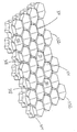
도 4a 는 도 2a 의 MEMS 필터 모듈의 필터 영역에 걸쳐서 이용될 수 있는 필터 영역 구성에 대한 일 구현예의 사시 단면도이다.4A is a perspective cross-sectional view of one embodiment of a filter region configuration that may be used across the filter region of the MEMS filter module of FIG. 2A.
도 4b 는 도 4a 의 필터 영역 구성에 의해서 이용된 한쌍의 필터 트랩에 대한 단면도이다.4B is a cross-sectional view of the pair of filter traps used by the filter region configuration of FIG. 4A.
도 4c 는 도 4a 의 필터 영역 구성에 의해서 이용된 하부 필름의 부분에 대한 사시도이다.4C is a perspective view of a portion of the bottom film used by the filter area configuration of FIG. 4A.
도 4d 는 도 4a 의 필터 영역 구성의 부분에 대한 사시도로서, 상부 필름이 제거된 것이다.FIG. 4D is a perspective view of a portion of the filter region configuration of FIG. 4A, with the top film removed. FIG.
도 4e 는 도 4a 의 필터 영역 구성의 상부 필름 부분에 대한 사시 저면도로 서, 필터 벽과 그로부터 연장된 지지부들을 도시한다.FIG. 4E is a perspective bottom view of the upper film portion of the filter region configuration of FIG. 4A, showing the filter wall and supports extending therefrom. FIG.
도 4f 는 도 4a 의 필터 영역 구성의 일부에 대한 사시도로서, 상부 필름이 하부 필름으로부터 분리된 것이다.4F is a perspective view of a portion of the filter region configuration of FIG. 4A, with the top film separated from the bottom film. FIG.
도 5a 는 도 2a 의 MEMS 필터 모듈의 필터 영역에 걸쳐서 이용될 수 있는 필터 영역 구성에 대한 다른 구현예의 단면도이다. 5A is a cross-sectional view of another embodiment of a filter region configuration that may be used across the filter region of the MEMS filter module of FIG. 2A.
도 5b 는 도 5a 의 필터 영역 구성에 의해서 이용되는 하부 필름의 부분에 대한 사시도이다.FIG. 5B is a perspective view of a portion of the lower film utilized by the filter area configuration of FIG. 5A. FIG.
도 5c 는 도 5a 의 필터 영역 구성에 대한 부분의 사시도로서, 상부 필름이 제거된 것이다.FIG. 5C is a perspective view of a portion of the filter area configuration of FIG. 5A, with the top film removed. FIG.
도 5d 는 도 5a 의 필터 영역 구성에 대한 상부 필름의 사시 저면도로서, 필터 벽과 지지부들이 그로부터 연장된다.FIG. 5D is a perspective bottom view of the top film for the filter area configuration of FIG. 5A, with the filter wall and supports extending therefrom. FIG.
도 5e 는 도 5a 의 필터 영역 구성에 대한 부분의 사시도로서, 상부 필름은 하부 필름으로부터 분리된 것이다. FIG. 5E is a perspective view of a portion of the filter area configuration of FIG. 5A, with the top film separated from the bottom film. FIG.
도 6a 는 도 2a 의 MEMS 필터 모듈의 필터 영역에 걸쳐서 이용될 수 있는 필터 영역 구성의 다른 구현예에 대한 단면도이다.6A is a cross-sectional view of another embodiment of a filter region configuration that may be used across the filter region of the MEMS filter module of FIG. 2A.
도 6b 는 도 6a 의 필터 영역 구성에 의해서 이용된 하부 필름의 부분에 대한 사시도이다.FIG. 6B is a perspective view of a portion of the bottom film used by the filter area configuration of FIG. 6A.
도 6c 는 도 6a 의 필터 영역 구성의 부분에 대한 사시도로서, 상부 필름이 제거되었다.FIG. 6C is a perspective view of a portion of the filter region configuration of FIG. 6A, with the top film removed. FIG.
도 6d 는 도 6a 의 필터 영역 구성의 상부 필름의 사시 저면도로서, 필터 벽 및 그로부터 연장된 지지부를 도시한다.FIG. 6D is a perspective bottom view of the top film of the filter region configuration of FIG. 6A, showing the filter wall and the support extending therefrom. FIG.
도 7a 는 도 2a 의 MEMS 필터 모듈의 필터 영역에 걸쳐서 이용될 수 있는 필터 영역 구성에 대한 다른 구현예의 사시 단면도이다.7A is a perspective cross-sectional view of another embodiment of a filter region configuration that may be used across the filter region of the MEMS filter module of FIG. 2A.
도 7b 는 도 7a 의 필터 영역에 의해서 이용된 하부 필름의 부분에 대한 상부 평면도이다. FIG. 7B is a top plan view of a portion of the bottom film used by the filter area of FIG. 7A. FIG.
도 7c 는 도 7a 의 필터 영역에 의해 이용된 하나의 중앙 지지부와 그것의 대응하는 고리형 지지부/시일의 상부 평면도이다.FIG. 7C is a top plan view of one central support and its corresponding annular support / seal used by the filter area of FIG. 7A. FIG.
도 7d 는 도 7a 의 필터 영역에 의해 이용된 하나의 고리형 필터 벽의 상부 평면도이다.FIG. 7D is a top plan view of one annular filter wall used by the filter region of FIG. 7A. FIG.
도 7e 는 도 7a 의 필터 영역에 의해 이용된 상부 필름 부분의 상부 평면도이다.FIG. 7E is a top plan view of the top film portion used by the filter area of FIG. 7A. FIG.
도 8a 는 도 2a 의 MEMS 필터 모듈의 필터 영역에 걸쳐서 이용될 수 있는 필터 영역 구성의 다른 구현예에 대한 사시 단면도이다. 8A is a perspective cross-sectional view of another embodiment of a filter region configuration that may be used across the filter region of the MEMS filter module of FIG. 2A.
도 8b 는 도 8a 의 필터 영역 구성에 의해 이용된 하부 필름의 부분에 대한 사시도이다.FIG. 8B is a perspective view of a portion of the bottom film used by the filter area configuration of FIG. 8A.
도 8c 는 도 8a 의 필터 영역 구성의 부분에 대한 사시도로서, 상부 필름이 제거된 것이다.FIG. 8C is a perspective view of a portion of the filter region configuration of FIG. 8A, with the top film removed. FIG.
도 8d 는 도 8a 의 필터 영역 구성에 대한 상부 필름 부분의 사시 저면도로서, 필터 벽과 그로부터 연장된 지지용 포스트들을 도시한다.FIG. 8D is a perspective bottom view of the upper film portion for the filter area configuration of FIG. 8A, showing the filter wall and supporting posts extending therefrom. FIG.
도 9a 는 도 2a 의 MEMS 필터 모듈의 필터 영역에 걸쳐서 이용될 수 있는 필 터 영역 구성의 다른 구현예에 대한 사시 단면도이다.9A is a perspective cross-sectional view of another embodiment of a filter region configuration that may be used across the filter region of the MEMS filter module of FIG. 2A.
도 9b 는 도 9a 의 필터 영역 구성에 의해 이용된 하부 필름 및 하부 지지부들의 부분에 대한 사시도이다.FIG. 9B is a perspective view of a portion of the lower film and the lower supports used by the filter area configuration of FIG. 9A. FIG.
도 9c 는 도 9b 에 도시된 하부 지지부상에 위치된 제 2 필름 부분들의 사시도이다.9C is a perspective view of second film portions located on the lower support shown in FIG. 9B.
도 9d 는 도 9a 의 필터 영역 구성에 의해 이용된 상부 지지부들 뿐만 아니라, 도 9b 에 도시된 제 2 필름 부분들 위에 위치된 필터 벽들의 사시도이다.FIG. 9D is a perspective view of filter walls located above the second film portions shown in FIG. 9B as well as the upper supports used by the filter area configuration of FIG. 9A.
도 9e 는 도 9a 의 필터 영역 구성의 부가적인 부분들에 대한 사시 단면도이다.9E is a perspective cross-sectional view of additional portions of the filter region configuration of FIG. 9A.
도 10a 는 MEMS 필터 모듈이 제조된 기판과 MEMS 필터 모듈 사이의 인터페이스(interface)의 일 구현예에 대한 사시도이다. 10A is a perspective view of one embodiment of an interface between a substrate on which a MEMS filter module is manufactured and an MEMS filter module.
도 10b 는 도 10a 의 MEMS 필터 모듈을 기판 위에 지지하도록 이용된 측방향 운동 제한부 및 링크(link)들중 하나에 대한 확대 사시도이다. FIG. 10B is an enlarged perspective view of one of the lateral motion limiters and links used to support the MEMS filter module of FIG. 10A over the substrate. FIG.
도 11a 는 MEMS 필터 모듈이 제조된 기판과 MEMS 필터 모듈 사이의 인터페이스에 대한 다른 구현예의 사시도이다.11A is a perspective view of another embodiment of an interface between a substrate on which a MEMS filter module is manufactured and an MEMS filter module.
도 11b 는 도 11a 의 MEMS 필터 모듈을 기판 위에 지지하도록 이용된 측방향 운동 제한부 및 링크들중 하나에 대한 확대 사시도이다.FIG. 11B is an enlarged perspective view of one of the lateral motion limiters and links used to support the MEMS filter module of FIG. 11A over the substrate. FIG.
도 12a 는 MEMS 필터 모듈을 이용하는 유동 조립체의 일 구현예에 대한 분해 사시도이다.12A is an exploded perspective view of one embodiment of a flow assembly using a MEMS filter module.
도 12b 는 도 12a 의 유동 조립체를 조립된 상태로 도시하는 사시도이다.FIG. 12B is a perspective view illustrating the flow assembly of FIG. 12A in an assembled state. FIG.
도 13a 는 MEMS 필터 모듈을 이용하는 유동 조립체의 다른 구현예에 대한 분해 사시도이다.13A is an exploded perspective view of another embodiment of a flow assembly utilizing a MEMS filter module.
도 13b 는 도 13a 의 유동 조립체를 조립된 상태로 도시하는 사시도이다.FIG. 13B is a perspective view illustrating the flow assembly of FIG. 13A in an assembled state. FIG.
도 14a 는 MEMS 필터 모듈을 이용하는 유동 조립체의 다른 구현예에 대한 분해 사시도이다.14A is an exploded perspective view of another embodiment of a flow assembly using a MEMS filter module.
도 14b 는 도 14a 의 유동 조립체를 조립된 상태로 도시하는 사시도이다.FIG. 14B is a perspective view showing the flow assembly of FIG. 14A in an assembled state. FIG.
도 15a 는 여기에 설명된 MEMS 필터 모듈중 그 어느 것이라도 이용할 수 있는 녹내장 또는 내안(intraocular) 임플란트의 일 구현예에 대한 사시도이다.FIG. 15A is a perspective view of one embodiment of a glaucoma or intraocular implant that may utilize any of the MEMS filter modules described herein. FIG.
도 15b 는 녹내장 또는 내안 임플란트 또는 션트(shunt)의 일 구현예에 대한 단면도로서, 이것은 눈의 전방 챔버내 압력을 경감시키도록 이용되고, 여기에 설명된 MEMS 필터 모듈중 그 어느 것이라도 이용할 수 있는 것이다.FIG. 15B is a cross-sectional view of one embodiment of a glaucoma or intraocular implant or shunt, which is used to relieve pressure in the anterior chamber of the eye and may be used with any of the MEMS filter modules described herein. will be.
본 발명은 이제 첨부된 도면을 참조하여 설명될 것인데, 도면은 다양한 관련 특징을 예시하는데 적어도 보조적인 것이다. 도 1 은 필터(10)의 일 구현예를 도시하는 것으로서, 이것은 서로에 대하여 고정된 관계로 유지되는 복수개의 이격된 플레이트들 또는 필름들로부터 형성된 MEMS 필터 모듈(34)을 이용한다. 이들 "필름"은 통상적으로 약 10 마이크론 보다 크지 않은 두께 또는 수직의 범위를 가질 것이며, 보다 전형적으로는 약 1 마이크론 내지 약 3 마이크론의 범위 이내의 두께를 가질 것이다. 그 어떤 경우에 있어서도, MEMS 필터 모듈(34)이 바람직스럽게는 필터 하우징(14) 안에 제거 가능하게 배치되며, 하우징(14)을 상부 챔버(26)와 하부 챔버(30)로 분리한다. 적어도 하나의 상부 유동 포트(port,18)가 상부 챔버와 유체 소통되기 위하여 하나의 위치에서 필터 하우징(14)을 통해 연장된다. 마찬가지로, 적어도 하나의 하부 유동 포트(22)는 하부 챔버(30)와 유체 소통되도록 하나의 위치에서 하우징(14)을 통해 연장된다. 유동은 도 1에서 화살표로 표시된 바와 같이 그 어떤 방향으로도 필터 하우징(14)을 통해 배향될 수 있다.The invention will now be described with reference to the accompanying drawings, which are at least auxiliary to illustrate various related features. 1 illustrates one embodiment of a filter 10, which utilizes a
필터 하우징(14)은 그 어떤 적절한 구성일 수 있고, 그 어떤 적절한 재료로부터 형성될 수 있고, 그 어떤 적절한 적용을 위해서도 이용될 수 있으며, 그 어떤 적절한 방식으로도 (바람직스럽게는 필터(10)를 통한 모든 유동이 MEMS 필터 모듈(34)을 통해서 향하도록 요구되는 방식으로) MEMS 필터 모듈(34)을 수용하고/그것에 맞물린다. 그 어떤 개수의 유동 포트(18,22)들이라도 상부 챔버(26) 및 하부 챔버(30)와 각각 관련될 수 있으며, 이들 유동 포트(18,22)들은 그 어떤 적절한 크기 및/또는 형상일 수 있다. 필터(10)의 상부 챔버(26)와 하부 챔버(30)가 MEMS 필터 모듈(34)로/그로부터 적절한 유동 경로를 제공하는 한, 상부 챔버(26)와 하부 챔버(30) 각각은 그 어떤 적절한 크기 및/또는 형상일 수도 있다.The
필터(10)는 그 어떤 적절한 적용예를 위해서 이용될 수 있다. 필터(10)를 통한 "유동"은 그 어떤 적절한 유형일 수 있으며(예를 들면, 연속성, 간헐성), 그 어떤 적절한 유체일 수 있다. 적어도 일부 유형의 힘(force)이 유체에 통상적으로 가해져서 필터(10)를 통한 유동을 제공한다. 이러한 힘은 그 어떤 적절한 소스로부터의 것일 수 있는데, 예를 들면 압력 소스(예를 들면, 펌프), 중력 또는 그것들의 조합과 같은 것이다. 그 어떤 경우에 있어서도, 필터(10)는 유체로부터 무엇인가를 제거하려고 시도한다. 필터(10)는, 필터(10)로부터의 유체 출력이 일부 소망의 목적을 위해서 이용되거나, 필터(10) 안에 유지된 물질이 일부 소망의 목적을 위해서 이용되거나, 또는 그것의 조합을 위해서 이용되도록 쓰일 수 있다.Filter 10 may be used for any suitable application. “Flow” through filter 10 may be of any suitable type (eg, continuity, intermittent), and may be any suitable fluid. At least some type of force is typically applied to the fluid to provide flow through the filter 10. This force may be from any suitable source, such as a pressure source (eg pump), gravity or a combination thereof. In either case, filter 10 attempts to remove something from the fluid. The filter 10 is such that the fluid output from the filter 10 is used for some desired purposes, or the material retained in the filter 10 is used for some desired purposes, or a combination thereof. Can be used.
MEMS 필터 모듈(34)에 관한 특정의 상세한 설명은 도 2a 내지 도 2f 에 도시되어 있다. 여기에는 MEMS 필터 모듈(34)의 2 개의 주요 부위 또는 영역들이 있는데, 즉, 필터 영역(38)과 주변 영역(42)이 있다. 적어도 2 개의 이격된 필름 또는 플레이트들이 필터 영역(38)과 주변 영역(42) 양쪽에서 MEMS 필터 모듈(34)에 의해 이용된다. 이하에 보다 상세하게 설명되는 바와 같이, 마이크로 제조 기술이 바람직스럽게는 MEMS 필터 모듈(34)을 적절한 기판(예를 들면 웨이퍼)상에 제조하도록 이용된다. 이와 관련하여 주목되는 것으로서, MEMS 필터 모듈(34)은 필터 하우징(14) 안에 설치되기 이전에 기판으로부터 분리된다.Specific details of the
MEMS 필터 모듈(34)은 제 1 플레이트 또는 필름(70)과 제 2 플레이트 또는 필름(46)을 구비하는데, 이들은 MEMS 필터 모듈(34)에서 이격된 관계 또는 상이한 높이로 배치된다. 바람직스럽게는, 이들 필름(70,46)들이 예상되는 유량/압력에 대하여 서로에 대하여 적어도 실질적으로 고정된 위치에 유지된다. 각각의 이들 필름(70,46)들은 MEMS 필터 모듈(34)의 극단을 형성할 수 있거나(예를 들면, MEMS 필터 모듈(34)의 하부 또는 상부 범위를 형성할 수 있거나), 또는 MEMS 필터 모듈(34) 안의 중간 위치에 배치될 수 있다(예를 들면, 2 개의 이격된 필름들 사이에 "개재(sandwich)되고, 이들 필름들 각각에 대하여 이격된 관계로 배치된다). 즉, 제 1 필름(70)은 MEMS 필터 모듈(34)의 하부 극단일 수 있거나, 또는 MEMS 필터 모 듈(34)의 상부 극단과 하부 극단 사이의 중간 위치에 있을 수 있다. 마찬가지로, 제 2 필름(46)은 MEMS 필터 모듈(34)의 상부 극단일 수 있거나 또는 MEMS 필터 모듈(34)의 상부 극단과 하부 극단 사이의 중간 위치에 있을 수 있다. 그 어떤 경우에 있어서도, 제 1 의 필름(70)은 복수개의 제 1 유동 포트(74)를 구비하는 반면에, 제 2 필름(46)은 복수개의 제 2 유동 포트(50)를 구비한다. 모든 제 1 유동 포트(74)들과 모든 제 2 유동 포트(50)들은 MEMS 필터 모듈(34)의 필터 영역(38) 안에 위치된다 (즉, 주변 영역(42)에 있지 않다).The
적어도 하나의 지지부(78)(예를 들면, 포스트 또는 칼럼(column))가 MEMS 필터 모듈(34)의 필터 영역(38)내에서 제 1 필름(70)과 제 2 필름(46) 사이에 연장되어 그들을 구조적으로 상호 연결시킨다. 바람직스럽게는, 복수개의 그러한 지지부(78)들이 반복되는 패턴과 서로에 대하여 이격된 관계로 필터 영역(38)을 통해 분포된다. 필터 영역(38) 내의 지지부(78)는 그 어떤 적절한 크기 및/또는 형상일 수도 있다. 적어도 하나의 필터 벽(54)이 제 2 필름(46)에 부착되고 그로부터 연장되어 적어도 제 1 필름(74)을 (제 1 필름의 방향으로) 향하여 연장된다. 각각의 그러한 필터 벽(54)은 제 2 필름(46)을 면하는 제 1 필름(70)의 제 1 표면에 도달하기 이전에 종료된다. 다른 방식으로 설명하자면, 각각의 필터 벽(54)은 제 1 필름(70)과 제 2 필름(46) 사이의 갭 보다 짧다. 더욱이, 각각의 필터 벽(54)은 복수개의 제 1 유동 포트(74)들 각각으로부터 오프셋(offset)된다. 즉, 제 2 필름(46)을 향하는 제 1 필름(70)의 제 1 표면으로 다양한 필터 벽(54)을 투사함으로써 형성되는 부위는 그 어떤 제 1 유동 포트(74)들도 둘러싸지 않는다. 바람직스럽게는, 각각의 필터 벽(54)이 예상되는 유량/압력을 위해서 제 1 필름(70)에 대하여 적어도 실질적으로 고정된 위치에 유지된다. At least one support 78 (eg, post or column) extends between the
그 어떤 개수의 필터 벽(54)이라도 필터 영역(38)에서 이용될 수 있다. 비록 그 어떤 개수의 지지부(78)라도 필터 영역(38)에서 이용될 수 있을지라도, 지지부(78)의 수와 위치는 필터 영역(38)을 위한 다수의 특성화(characterization)를 받아야 한다. 그 중 하나는 각각의 필터 벽(54)이 그것과 결합된 적어도 하나의 지지부(78)를 바람직스럽게 가지는 것이다. 다른 것은 필터 벽(54)이 있는 만큼 적어도 지지부(78)들이 있는 것이다. 다른 것은 근접한 지지부(78)의 각각의 쌍 사이에 있는 최대의 간격이 일 구현예에서 약 100 마이크론보다 크지 않고, 보다 전형적으로는 다른 구현예에서 약 5 마이크론내지 약 20 마이크론의 범위내에 있는 것이다.Any number of
MEMS 필터 모듈(34)의 각각의 필터 벽(54)이 바람직스럽게는 고리형의 형상을 가진다. 상기 문맥에서 "고리형(annular)"은 필터 벽(54)의 말단 단부에서(제 2 필름(46)과 인터페이스(interface)된 필터 벽(54)의 단부에 반대인 것) 보았을 때 필터 벽(54)이 폐쇄된 주위를 가지는 것을 의미한다. 다른 방식으로 설명하면, 각각의 필터 벽(54)은 그 어떤 적절한 경로를 다라서 특정의 기준 축을 중심으로 완전한 360 도로 연장된다. 그 어떤 형상이라도 필터 벽(54)을 위한 소망의 고리형 범위를 구현하도록 이용될 수 있다 (예를 들면, 원형, 타원형, 정사각형, 직사각형). 각각의 필터 벽(54)은 또한 위에서 주목된 바와 같이 제 1 필름(70)으로 전체가 연장되지 않는다. 대신에, 필터 트랩(filter trap) 또는 필터 트랩 갭(58)이 각각의 필터 벽(54)의 말단 단부와 제 1 필름(70) 사이에서 배출된다. 각각의 필터 벽(54)은 바람직한 형상에 있어서 고리형이므로, 각각의 필터 트랩 갭(58)은 마찬가지로 고리형일 것이다. 따라서, 특정한 필터 트랩 갭(58)을 통과할 수 없어서 "포획되는" 그 어떤 성분이라도 완전하게 이러한 필터 트랩 갭(58)을 "틀어막는"(plug) 것은 아니다. 고리형 필터 트랩 갭(58)을 각각의 벽(54)과 결합시키는 것은 MEMS 필터 모듈(34)을 통해 소망의 유량을 제공한다. Each
유동은 제 2 유동 포트를 통해서 (이러한 경우에 MEMS 필터 모듈(34) 밖으로의 유동은 제 1 유동 포트(74)를 통하게 될 것이다) 또는 제 1 유동 포트(74)를 통해서 (이러한 경우에 MEMS 필터 모듈(34) 밖으로의 유동은 제 2 유동 포트(50)를 통하게 될 것이다) MEMS 필터 모듈(34)로 진입할 수 있다. 어느 경우에도, 특정의 필터 벽(54)과 관련된 필터 트랩 갭(58)을 통과하는 것을 시도하기 이전에 제 1 필름(70)으로부터 제 2 필름(46)으로 연장된 공간(62)으로 유동이 향하게 될 것이다. 필터 영역(38) 안의 이들 공간(62)들 각각은 필터 트랩 챔버(62)로서 특징지워질 수 있다. 각각의 필터 트랩 챔버(62)의 높이는 제 1 필름(70)과 제 2 필름(46) 사이의 간격에 해당하며, 이것은 필터 트랩 갭(58)의 높이 보다 크다. 필요 조건인 것은 아닐지라도, 각각의 필터 트랩 챔버(62)의 체적은 그 어떤 관련된 제 1 유동 포트(70)의 체적보다 클 수 있으며, 그 어떤 관련된 제 2 유동 포트(50)의 체적보다 클 수 있다. 유동이 MEMS 필터 모듈(34)에 제 1 유동 포트(74)를 통해서 진입하든 또는 제 2 유동 포트(50)를 통해서 진입하든, 유동은 필터 트랩 챔버(62)를 통과할 것이며, 다음에 필터 트랩 갭(58)을 통하여, 그리고 다음에 다른 필터 트랩 챔버(62)를 통과할 것이다. 비록 각각의 필터 트랩 챔버(62)가 같은 형상 및 체적 을 가질 수 있을지라도, 일 구현예에서, 적어도 일부의 측면에서 (예를 들면, 상이한 체적/형상들) 서로 상이한 필터 트랩 챔버(62)들의 2 가지 별개의 그룹들이 존재한다. Flow is through the second flow port (in this case flow out of the
위에서 지적된 바와 같이, 유동은 필터(10)를 통하여 그 어떤 방향으로도 향할 수 있다. 하나 또는 그 이상의 제 1 유동 포트(74)들은 (단일 필터 벽(54)에 의해 경계가 정해진 필터 트랩 챔버(62)와 유체 상호 연결되기 위하여) 각각의 필터 벽(54)의 내측으로 배치될 수 있는 반면에, 하나 또는 그 이상의 제 2 유동 포트(50)들은 (다수의 필터 벽(54)들 사이의 간격에 의해 정해진 필터 트랩 챔버(62)와 유체 상호 연결되기 위하여) 각각의 필터 벽(54)의 주위를 지나서 배치될 수 있다 (도 2e). 역으로, 하나 또는 그 이상의 제 2 유동 포트(50)는 (단일 필터 벽(54)에 의해 경계가 정해진 필터 트랩 챔버(62)와 유체 상호 연결되기 위하여) 각각의 필터 벽(54)의 내측으로 배치될 수 있는 반면에, 하나 또는 그 이상의 제 1 유동 포트(74)들은 (다수의 필터 벽(54)들 사이의 간격에 의해 형성된 필터 트랩 챔버(62)와 유체 상호 연결되기 위하여) 필터 벽(54)의 외주를 지나서 배치될 수 있다 (도 2e). 그 어떤 경우에라도, 유동은 MEMS 필터 모듈(34)에서 배출되기 전에 필터 벽(54)에 의해 부분적으로 형성된 필터 트랩 갭(58)을 통과하도록 요구된다. As pointed out above, the flow can be directed in any direction through the filter 10. One or more
MEMS 필터 모듈(34)을 통한 유동에 관련된 다수의 특성들이 존재한다. 그 중 하나는 MEMS 필터 모듈(34)을 통한 유동이 축방향이 아니어서 적어도 하나의 방향 변화를 겪어야만 한다는 점이며, 필터 트랩 갭(58)을 통한 유동하는 것을 제한 없이 포함한다. 다른 특성은 필터 트랩 갭(58)을 통한 유동의 방향이 제 1 필름(70) 및 제 2 필름(46)과 적어도 전체적으로 평행한 차원이라는 점이다. 다른 특성은 필터 트랩 갭(58)을 통한 유동이 제 1 필름(70)과 제 2 필름(46) 양쪽을 통한 유동의 방향에 적어도 전체적으로 직교한다는 것이다.There are a number of characteristics related to flow through the
유동은 필터 기능을 제공하도록 필터 트랩 갭(58)을 통해 배향된다. 필터 트랩 갭(58)의 높이 보다 큰 그 어떤 유동의 성분 (예를 들면, 적어도 특정 크기의 세포, 미립자)이라도 필터 벽(54)과 제 1 필름(70)에 의해서 (즉, 필터 갭(58)을 통과할 수 없어서) 보통은 수집되어 유지될 것이다. MEMS 필터 모듈(34)이 설계되었던 최대 유량에 대하여, 필터 영역(38)을 통한 각각의 필터 트랩 갭(58)의 높이가 작은 공차 이내로 유지되도록 다양한 지지부(78)들의 수와 위치가 바람직스럽게 선택된다. 각각의 필터 트랩 갭(58)의 높이가 약 0.4 마이크론 또는 그 미만인 경우에, 필터(10)를 통하여 필터의 최대 설계 유량으로 가동되었을 때 필터 트랩 갭(58)이 단지 약 수십의 나노미터로 (예를 들면, 제 1 필름(70) 및/또는 제 2 필름(46)의 편향에 기인하여) 변화되도록, 지지부(78)는 필터 영역(38)을 통해 분포된다.Flow is oriented through the
하나 또는 그 이상의 고리형 시일(66)들이 MEMS 필터 모듈(34)의 주위 영역(42)에 위치되며, MEMS 필터 모듈(34)의 필터 영역(38)에 대한 경계 또는 주위를 형성한다. 고리형 시일(들)(66)과 관련하여 "고리형"이 의미하는 것은 고리형 시일(들)이 "측방향"의 차원에서 MEMS 필터 모듈(34)의 필터 영역(38)에 대한 폐쇄된 주위 또는 경계를 형성한다는 점이다. 다른 방법으로 설명하자면, 각각의 시일(66)은 특정의 축 둘레에서 완전히 360 도로 연장된다. 그 어떤 경우에라도, 제 1 필 름(70)과 연관된 모든 제 1 유동 포트(74) 및 제 2 필름(46)과 연관된 모든 제 2 유동 포트(50)들은 각각의 고리형 시일(60)의 내측으로 배치된다. 그 어떤 개수의 고리형 시일(66)이라도 이용될 수 있으며 (도시된 구현예에서는 3 개), 바람직스럽게는 측방향의 차원에서 MEMS 필터 모듈(34)의 필터 영역(38)에 대한 여분의 시일링 성능을 제공하도록 측방향으로 이격된 관계로 동심상으로 배치된다. 즉, 고리형 시일(66)은 적어도 MEMS 필터 모듈(34)의 필터 영역(38)을 통하여 모든 유동이 강제되도록 시도한다. 각각의 고리형 시일(66)들은 같은 폭일 수 있거나, 또는 적어도 하나의 고리형 시일(66)이 상이한 폭일 수 있다. 일 구현예에서, 가장 외측으로 배치된 고리형 시일(66)은 그 어떤 다른 고리형 시일(66) 보다 넓다.One or more
MEMS 필터 모듈(34)에 의해 이용된 각각의 고리형 시일(66)의 다른 기능은 MEMS 필터 모듈(34)에 구조적인 강도나 강성을 제공하는 것이다. 각각의 고리형 시일(66)은 MEMS 필터 모듈(34)의 주위 영역(42)에서 제 1 필름(70)을 제 2 필름(46)과 구조적으로 상호 연결시킨다. 이것은 MEMS 필터 모듈(34)의 물리적인 구조를 손상시키는 잠재성을 감소시키는 방식으로 MEMS 필터 모듈(34)을 취급/연계하는데 이용될 수 있다. MEMS 필터 모듈(34)의 주위 영역(42)이 바람직스럽게는 MEMS 필터 모듈(34)의 필터 영역(38) 보다 단단하다. 주위 영역(42)이 따라서 필터 하우징(14) 또는 중간 시일링 구조와의 맞물림을 위하여 소망스러운, 충분히 강건한 계면(interface)을 제공할 수 있다. 주위 영역(42)의 폭은 일 구현예에서 적어도 약 3 또는 4 마이크론이며, 다른 구현예에서 약 20 마이크론내지 약 25 마이크론 정도일 수 있다.Another function of each
제 1 필름(70)(복수개의 제 1 유동 포트(74)를 가짐) 및 제 2 필름(46)(복수개의 제 2 유동 포트(50)를 가짐) 양쪽은 각각의 고리형 시일(66)에 의해서 개별의 주위 영역의 둘레에서 지지된다. 즉, 제 1 필름(70)(복수개의 제 1 유동 포트(74)를 가짐) 및 제 2 필름(46)(복수개의 제 2 유동 포트(50)를 가짐) 양쪽은 MEMS 필터 모듈(34)을 통해서 연속적인 구조이다. 다른 방식으로 설명하면, MEMS 필터 모듈(34)의 주위 영역(42)의 일 위치로부터 제 1 필름(70)을 다라서, 필터 영역(38)을 통하여, 제 1 필름(70)에 의해 형성된 연속 경로를 따라서 주위 영역(42)의 그 어떤 다른 위치로 (가능하게는 굽이치는 경로를 따르는 것일지라도) 전진할 수 있다. 마찬가지로, MEMS 필터 모듈(34)의 주위 영역(42)의 일 위치로부터 제 2 필름(46)을 따라서, 필터 영역(38)을 통하여, 제 2 필름(46)에 의해 형성된 연속적인 경로를 다라서 주위 영역(42)의 그 어떤 다른 위치로 (가능하게는 굽이치는 경로를 따르는 것일지라도) 전진될 수 있다. Both the first film 70 (having a plurality of first flow ports 74) and the second film 46 (having a plurality of second flow ports 50) are provided on each
MEMS 필터 모듈(34)은 그 어떤 개수의 필름으로도 형성될 수 있고, 그 어떤 적절한 재료로부터라도 형성될 수 있고, 소망되는 적용을 위한 그 어떤 적절한 형상일 수도 있으며, 평면도에서 그 어떤 적절한 형상일 수도 있다 (도 2a). 바람직스럽게는, 제 1 필름(70), 제 2 필름(46), 필터 벽(들)(54), 지지용 포스트(support post)(들)(78) 및 고리형 시일(들)이, 도 3a 내지 도 3i에 관련하여 아래에 보다 상세하게 설명될 바와 같이, 표면 마이크로가공에 의한 제조의 목적을 위해서 같은 재료로 (예를 들면, 폴리실리콘) 형성된다. 필터 벽(54)은 바람직한 구현예를 위한 고리형 범위를 형성하는 그 어떤 형상일 수도 있는데, 원형, 타원 형, 삼각형, 정사각형 또는 직사각형을 제한 없이 포함한다. 마찬가지로, 각각의 고리형 시일은 고리형 범위를 형성하는 그 어떤 형상일 수도 있으며, 제한 없이 원형, 타원형, 삼각형, 정사각형 또는 직사각형을 포함한다.The
비록 바람직스럽게는 복수개의 제 1 유동 포트(74)와 복수개의 제 2 유동 포트(50)가 그 어떤 특정한 필터 트랩 갭(58)을 통한 유동을 제공할 수 있을지라도, 그 어떤 개수의 제 1 유동 포트(74)와 그 어떤 개수의 제 2 유동 포트(50)가 이용될 수 있다. 즉, 적어도 2 개의 제 1 유동 포트(74)와 적어도 2 개의 제 2 유동 포트(50)가 바람직스럽게는 각각의 필터 벽(54)과 연관된다. 따라서, 개별적인 제 1 유동 포트(74) 또는 제 2 유동 포트(50)의 그 어떤 "틀어막힘(plugging)"도 완전하게 그 어떤 하나의 필터 트랩 갭(58)을 무능화시키지 않아야 한다. 다른 선택안은 제 1 유동 포트와 제 2 유동 포트를 완전히 차단시킬 수 있는 단일의 입자 또는 성분의 잠재성이 감소되도록 제 1 유동 포트(74)와 제 2 유동 포트(50)의 크기를 정하고 형상화하는 것이다. 그 어떤 경우에 있어서도, 양족의 제 1 유동 포트(74)와 제 2 유동 포트(50)는 그 어떤 적절한 크기 및/또는 형상일 수 있으며, MEMS 필터 모듈(34)을 통한 소망의 유동과 제 1 필름(70) 및 제 2 필름(46) 사이에서 연장되는 지지부(78)의 소망되는 개수/배치를 수용하는 것을 제한 없이 포함한다. 바람직스럽게는, 제 1 유동 포트(74), 제 2 유동 포트(50), 필터 벽(54) 및, 지지부(78)를 위한 MEMS 필터 모듈(34)의 필터 영역(38)을 통하여 반복 패턴이 이용된다. Although the plurality of
본원에 설명된 다양한 필터 모듈에 대한 바람직한 제조 기술은 표면 마이크로 가공(micro-machining)이다. 표면 마이크로 가공은 적절한 기판(예를 들면 실리 콘 웨이퍼)을 이용하여 구조 물질(structural material)과 희생 물질(sacrificial material)의 교번하는 층들을 증착시키는 것을 수반하는데, 상기 기판은 결과적인 마이크로구조에 대한 기초로서 기능한다. 소망되는 마이크로 구조를 형성하기 위하여, 다음의 층이 증착되기 이전에 다양한 패터닝 작용(마스킹(masking), 에칭 및, 마스크 제거 작용을 포괄적으로 포함한다)이 상기 층들의 하나 또는 그 이상의 것 위에서 수행될 수 있다. 이러한 일반적인 방식으로 마이크로 구조가 형성된 이후에, 다양한 희생 층들의 전부 또는 일부가 마이크로 구조 및 다양한 희생층들을 하나 또는 그 이상의 식각제(etchant)에 노출시킴으로써 제거된다. 이것은 보통 기판으로부터 마이크로구조를 "해제(releasing)"시키는 것으로 지칭되며, 통상적으로 마이크로구조와 기판 사이에서 적어도 일부 정도의 상대적인 운동을 허용한다. 특히 소망스러운 표면 마이크로 가공 기술은 2000년 7 월 4 일자의 미국 특허 제 6,082,208 호의 "5 개 레벨의 마이크로전자기계 구조의 제조 방법 및 그에 의해 형성된 마이크로전자기계 트랜스미션"에 개시되어 있으며, 상기 특허의 전체 개시 내용은 본원에 참조로서 포함된다(이후에 '208 특허로서 지칭한다).A preferred manufacturing technique for the various filter modules described herein is surface micro-machining. Surface micromachining involves depositing alternating layers of structural and sacrificial materials using a suitable substrate (e.g. a silicon wafer), the substrate being subjected to the resulting microstructure. It serves as the basis. In order to form the desired microstructure, various patterning operations (including masking, etching, and mask removing operations) may be performed on one or more of the layers before the next layer is deposited. Can be. After the microstructures are formed in this general manner, all or some of the various sacrificial layers are removed by exposing the microstructures and the various sacrificial layers to one or more etchants. This is commonly referred to as "releasing" the microstructures from the substrate, and typically allows at least some degree of relative movement between the microstructures and the substrate. Particularly desired surface micromachining techniques are disclosed in US Pat. No. 6,082,208, entitled "Methods for Manufacturing Five Levels of Microelectromechanical Structures and Microelectromechanical Transmissions Formed thereby," dated July 4, 2000. The disclosure is incorporated herein by reference (hereinafter referred to as the '208 patent).
여기에서 사용된 용어인 "희생 층 또는 필름"은 마이크로 구조를 제조하도록 이용된 그 어떤 표면 마이크로가공된 마이크로 구조의 그 어떤 층이나 또는 부분을 의미하지만, 그것은 일반적으로 최종의 구성에 존재하지 않는다 (예를 들면, 희생 물질은 하나 또는 그 이상의 목적을 위해서 하나 또는 그 이상의 위치에서 구조 물질에 의해 쌓여질(encase) 수 있으며, 결과적으로 이렇게 쌓여진 물질은 해제에 의해서 제거되지 않는다). 여기에서 설명된 희생층을 위한 예시적인 물질들은 도핑되 지 않은 실리콘 이산화물 또는 실리콘 산화물 및, 도핑된 실리콘 이산화물 또는 실리콘 산화물을 포함한다 ("도핑된" 이라는 것은 부가적인 구성 요소의 물질이 증착 동안에 또는 그 이후에 필름에 부가된 것을 나타낸다). 여기에서 사용된 "구조 층 또는 필름"이라는 용어는, 희생층 및, 마이크로 구조가 제조되는 기판이 아닌 표면 마이크로가공된 마이크로 구조의 그 어떤 다른 층 또는 부분을 의미한다. 여기에서 설명된 구조층에 대한 예시적인 물질들은 도핑되거나 또는 도핑되지 않은 폴리실리콘과 도핑되거나 또는 도핑되지 않은 실리콘을 포함한다. 여기에서 설명된 기판을 위한 예시적인 물질은 실리콘을 포함한다. 여기에 설명된 다양한 층들은, 저압 CVD(LPCVD), 대기압 CVD (APCVD) 및, 플라즈마 강화 CVD (PECVD)를 포함하는 화학적 증기 증착(CVD), 열 산화 방법 및, 증발성 PVD 및 스터터링 PD를 포함하는 물리적 증기 증착(PVD)과 같은 기술에 의해서 형성되고/증착될 수 있다.As used herein, the term “sacrificial layer or film” means any layer or portion of any surface microfabricated microstructure used to make a microstructure, but it is generally not present in the final configuration ( For example, the sacrificial material may be encased by the structural material at one or more locations for one or more purposes, and consequently this stacked material is not removed by release). Exemplary materials for the sacrificial layer described herein include undoped silicon dioxide or silicon oxide, and doped silicon dioxide or silicon oxide ("doped" means that the material of the additional component is deposited or Then added to the film). As used herein, the term "structural layer or film" refers to the sacrificial layer and any other layer or portion of the surface microfabricated microstructure, not the substrate from which the microstructure is made. Exemplary materials for the structural layers described herein include doped or undoped polysilicon and doped or undoped silicon. Exemplary materials for the substrates described herein include silicon. The various layers described herein include chemical vapor deposition (CVD), thermal oxidation methods, including low pressure CVD (LPCVD), atmospheric pressure CVD (APCVD), and plasma enhanced CVD (PECVD), and evaporative PVD and stuttering PD. It may be formed / deposited by techniques such as incorporating physical vapor deposition (PVD).
보다 일반적으로 설명하자면, 표면 마이크로가공은 기판, 희생 필름(들) 또는 층(들) 및, 구조 필름(들) 또는 층(들)의 그 어떤 적절한 시스템으로 이루어질 수 있다. 비록 실리콘 웨이퍼의 가용성과 어디에서 이용 가능한 특성 때문에 실리콘 웨이퍼를 이용하는 경향이 있을지라도, 많은 기판 재료들이 표면 마이크로가공 작용에서 이용될 수 있다. 기판은 실질적으로 마이크로구조가 그 위에 제조되는 기초이다. 이러한 기초 물질은 마이크로구조(들)를 형성하도록 이용되고 있는 공정들에 대하여 안정적이어야 하며, 마이크로구조(들)를 형성하도록 이용되고 있는 희생/구조 필름들의 처리에 부정적인 영향을 미칠 수 없다. 희생 필름 및 구조 필름들과 관련하여, 주요한 구분 인자는 소망되는/필요한 해제 식각제(들)에 대한 희생 필름과 구조 필름 사이의 선택성 편차이다. 이러한 선택성 비율은 약 10:1의 정도일 수 있으며, 보다 바람직스럽게는 수백 대 1 이거나 또는 그 이상이며, 무한의 선택성 비율이 보다 바람직스럽다. 그러한 희생 필름/구조 필름 시스템의 예는 다음과 같은 것을 포함한다: 다양한 실리콘 산화물/실리콘의 다양한 형태; 폴리 게르마늄/폴리 게르마늄-실리콘; 다양한 폴리머 필름/다양한 금속 필름 (예를 들면, 포토레지스트/알루미늄); 다양한 금속/다양한 금속(예를 들면, 알루미늄/니켈); 폴리실리콘/실리콘 카바이드; 실리콘 이산화물/폴리실리콘 (즉, 예를 들면, 포타쥼 수산화물과 같은 상이한 해제 식각제를 이용)등이 포함된다. 실리콘 이산화물 및 실리콘 산화물 희생 물질들에 대한 해제 식각제의 예들은 통상적으로 불화 수소(HF)산 계열이다 (예를 들면, 실질적으로 49 wt% HF 산 및 51 wt% 의 물로 되어 있는, 농후 HF 산; 물을 가진 농후 HF 산; 완화(buffered) HF 산 (HF 산 및 암모늄 불화물)).More generally, surface micromachining may consist of any suitable system of substrate, sacrificial film (s) or layer (s) and structural film (s) or layer (s). Although substrate substrates tend to use silicon wafers because of their availability and the properties available there, many substrate materials can be used in surface micromachining operations. The substrate is substantially the basis on which the microstructures are fabricated. This base material must be stable to the processes being used to form the microstructure (s) and cannot negatively affect the treatment of the sacrificial / structural films being used to form the microstructure (s). With regard to the sacrificial film and the structural films, the main distinguishing factor is the selectivity deviation between the sacrificial film and the structural film for the desired / needed release etchant (s). This selectivity ratio may be on the order of about 10: 1, more preferably hundreds to one or more, and an infinite selectivity ratio is more preferred. Examples of such sacrificial film / structural film systems include the following: various forms of various silicon oxides / silicones; Poly germanium / poly germanium-silicon; Various polymer films / various metal films (eg photoresist / aluminum); Various metals / various metals (eg aluminum / nickel); Polysilicon / silicon carbide; Silicon dioxide / polysilicon (ie, using a different release etchant such as, for example, Potassium hydroxide), and the like. Examples of release etchant for silicon dioxide and silicon oxide sacrificial materials are typically hydrogen fluoride (HF) acid series (e.g., enriched HF acid, substantially consisting of 49 wt% HF acid and 51 wt% water). Enriched HF acid with water; buffered HF acid (HF acid and ammonium fluoride).
도 3a 는 기판(80) 위에 형성되었던 제 1 의 희생 필름(84)을 도시한다('208 특허에 설명된 공정에서 통상적으로 SacOx1 층 또는 레벨로 지칭되었음).비록 제 1 의 희생 필름(84)이 기판(80)상에 직접적으로 형성될 수 있을지라도, 통상적으로 하나 또는 그 이상의 중간 층들 또는 필름들이 있다 (도시되지 않았지만, '208 특허에 설명된 공정에서 P0 층 또는 레벨로서 지칭된 것으로서, 그로부터 전기적인 자취(trace)등이 형성되는데, 이들은 산화물 또는 질화물 필름 또는 층에 의해서 기판 물질로부터 차례로 분리된 것이다.) 그 어떤 경우에라도, 제 1 필름(88)('208 특허에 설명된 공정에서는 통상적으로 조합된 P2/P1 층 또는 제조 레 벨로서 지칭되었다)이 제 1 의 희생 필름(84)상에 형성된다. 제 1 의 필름(88)은 다음에 도 3b 에 도시된 바와 같이 제 1 의 유동 포트 통공(92)을 형성하도록 패턴화된다. 이러한 제 1 의 유동 포트 통공(92)은, MEMS 필터 모듈이 제조의 종료시에 해제되면, 제 1 필름(88)을 위한 제 1 의 유동 포트(120)가 된다(도 3I). 3A shows a first
제 2 의 희생 필름(94)('208 특허에 설명된 공정에서 통상적으로 SacOx3 층 또는 레벨로 지칭되었다)은 제 1 필름(88)에 형성된다 (도 3c). 이러한 제 2 의 희생 필름(94)은 제 1 필름(88)에 있는 제 1 유동 포트 통공(92) 안으로 연장되어서 통상적으로는 적어도 실질적으로 그것을 "채운다". 제 2 의 희생 필름(94)은 다음에 필터 벽 통공(98)을 형성하도록 패턴화된다 (도 3d). 이러한 필터 벽 통공(98)은 제 1 필름(88)까지 연장된다. 통상적으로, 제 2 희생 필름(94)은 과도 에칭(over-etching)될 것이어서, 제 1 필름(88)의 상부 표면의 작은 부분은 필터 벽 통공(98)의 형성에 의해서도 에칭될 것이다. 즉, 필터 벽 통공(98)을 형성하는 제 2 희생 필름(94)의 패턴화 이후에, 제 2 희생 필름(94)내의 필터 벽 통공(98)과 대응하는 제 1 필름(88)의 상부 표면상에 작은 요부(미도시)가 있을 수 있다.A second sacrificial film 94 (commonly referred to as a SacOx3 layer or level in the process described in the '208 patent) is formed in the first film 88 (FIG. 3C). This second
도 3e 는 부가적인 희생 물질(102)이 제 2 희생 필름(94)의 상부 표면상에 형성된 것을 도시한다. 비록 제 2 희생 필름(94)에 있는 희생 물질(102)이 도 3e 내지 도 3h에서 분리된 구조로 도시되었을지라도, 이러한 희생 물질(102)은 실질적으로 제 2 희생 필름(94)과 거의 구분이 불가능하며 그것의 일부가 된다. 희생 물질(102)은 제 2 희생 필름(94)에 있는 필터 벽 통공(98)에 의해 노출된 제 1 필름(88)의 표면에 증착된다. 특정한 양의 희생 물질(102)이 제 2 희생 필름(94)에 있는 필터 벽 통공(98)의 측벽에 증착되는 것도 가능할 것이다(미도시). 희생 물질(102)의 두께는 매우 정확하게 제어될 수 있으며 결과적인 MEMS 필터 모듈에서 필터 트랩 갭(123)의 두께를 형성하도록 이용된다 (도 3i). 예를 들면, 목표 두께의 +/- 2 % 의 공차내에서 희생 물질(102)을 증착시킬 수 있다.3E shows that additional
희생 물질(102)의 필름은 다음에 지지용 포스트 통공(106)을 형성하도록 패턴화되는데, 상기 지지용 포스트 통공은 제 1 필름(88)의 상부 표면의 대응 부분을 노출시킨다 (도 3f). 즉, 지지용 포스트 통공(106)은 희생 물질(102)의 층을 통하여 그리고 제 2 희생 필름(94)을 통하여 아래에 놓인 제 1 필름(88)으로 완전히 연장된다. 다음에 제 2 필름(110)은 제 1 필름(88)과는 상이한 제조 레벨에서 도 3g 에 도시된 바와 같이 희생 물질(102)의 층의 상부 표면에 형성된다. 이러한 제 2 필름(110)은: 1) MEMS 필터 모듈을 위한 지지부(118)를 형성하기 위하여 제 2 희생 필름(94)과 희생 물질(102)의 층에 있는 지지용 포스트 통공(106) 및 ; 2) MEMS 필터 모듈을 위한 필터 벽(121)을 형성하기 위하여 제 2 희생 필름(94)과 희생 물질(102)의 층에 있는 필터 벽 통공(98)의 안에서 연장되고, 보통 적어도 실질적으로 그것을 "채운다". 필터 벽(121)의 말단 단부 (도 3i)는 희생 물질(102)의 대응하는 부분에 의해서 제 1 필름(88)으로부터 이격된다 (도 3g). 이러한 희생 물질(102)은 필터 트랩 또는 필터 트랩 갭(123)을 형성하도록 필터 모듈의 해제에 의해 제거된다 (도 3i). The film of
제 2 필름(110)은 다음에 도 3h 에 도시된 바와 같이 제 2 유동 포트 통공(114)을 형성하도록 패턴화된다. 제 2 유동 포토 통공(114)은, MEMS 필터 모듈이 제조의 종료시에 해제되었을 때, 제 2 필름(110)을 위한 제 2 유동 포트(122)가 될 것이다. 이와 관련하여 도 3i를 참조하면, "적층부(stack)"는 적절한 식각제에 노출되는데, 식각제는 제 1 희생 필름(84), 제 2 희생 필름(94) 및 희생 물질(102)을 제거한다. 이후에 보다 상세하게 설명되는 바와 같이, MEMS 필터 모듈은 해제(미도시) 이후에 기판(80)의 위에 구조적으로 지지되어 유지될 수 있다. 그러나, MEMS 필터 모듈은 도 10a 내지 도 11b 와 관련하여 이후에 보다 상세하게 설명되는 바와 같이, 필터(10)로 통합되도록 기판(80)으로부터 궁극적으로 분리된다. The
MEMS 필터 모듈의 다양한 구현예들은 도 4a 내지 8d 에 도시되어 있으며, 이들은 도 2a 내지 도 2f 에 도시된 MEMS 필터 모듈(34)의 원리에 따른 것이다. 본원에서 다르게 지적되지 않는 한, MEMS 필터 모듈(34)에 대한 설명은 이들 MEMS 필터 모듈들 각각에 대하여 동등하게 적용될 수 있다. 이들 MEMS 필터 모듈들에 의해서 이용되는 MEMS 필터 모듈(34)의 구성 요소들에 관해서는 위에 설명된 바를 참조하여야 한다. 더욱이, 상기 MEMS 필터 모듈들 각각은 도 1 의 필터(10)에서 MEMS 필터 모듈(34) 대신에 이용될 수 있다. 이들 각각의 경우에, 필터 기능을 제공하도록 협동하는 필름 또는 플레이트들은 예상된 유동 비율/압력에 관하여 서로에 대해서 적어도 실질적으로 고정된 지점으로 유지된다. 더욱이, 필터 트랩 갭을 형성하도록 협동하는 각각의 필터 벽과 필름 또는 플레이트는 서로에 대하여 적어도 실질적으로 고정된 지점에 유지된다.Various implementations of the MEMS filter module are shown in FIGS. 4A-8D, which are in accordance with the principles of the
도 4a 내지 도 4f 는 필터 영역(126)을 가지는 MEMS 필터 모듈(124)을 도시한다. 필터 모듈(124)은 이격된 관계로 또는 상이한 높이로 증착된 제 1 필름(130) 과 제 2 필름(138)을 구비한다. 각각의 이들 필름(130,138)은 필터 영역(126)과 그것의 주위 영역(42) 양쪽에서 필터 모듈(124)에 대한 극단부(extreme)를 형성한다 (도시되지 않았지만, 도 2a 내지 도 2f 의 구현예에 따라서 이루어진다). 따라서, 필름(130,138)은 필터 모듈(124)에 의해서 이용된 각각의 고리형 시일(66)에 의해서 개별의 주위 영역의 둘레에서 상호 연결되고 지지된다. 필름(130,138)들은 필름(70,46)과 관련하여 위에서 설명된 것과 같은 방식으로 "연속적인" 구조이다. 4A-4F show a
제 1 필름(130)은 복수개의 제 1 유동 포트(134)들을 구비하는 반면에, 제 2 필름(138)은 복수개의 제 2 유동 포트(142)들을 구비한다. 모든 제 1 유동 포트(134)들과 모든 제 2 유동 포트(142)들은 필터 모듈(124)의 필터 영역(126)에만 위치된다. 복수개의 지지부(154)들은 필터 영역(126)에서 제 1 필름(130)과 제 2 필름(138) 사이에서 연장되어 그들을 구조적으로 상호 연결시킨다. 이들 지지부(154)들은 반복되는 패턴으로 필터 영역(126)에 걸쳐서 분포되고, 서로 이격된 관계로 배치되며, 그 어떤 적절한 구성일 수 있다. 복수개의 필터 벽(150)들은 제 2 필름(138)에 부착되어 그로부터 연장되며 적어도 제 1 필름(130)을 향하여 (그것의 방향으로) 연장된다. 그 어떤 개수의 필터 벽(150)이라도 필터 모듈(124)의 필터 영역(126)에서 이용될 수 있다. 비록 그 어떤 개수의 지지부(154)라도 이용될 수 있지만, 지지부(154)들의 수와 위치는 지지부(78)들과 관련하여 위에서 설명된 것과 같은 특성화를 받게 된다. 더욱이 필터 모듈(124)의 필터 영역(126)의 경우에 대하여, 하나의 지지부(154)가 중앙 위치에서 각각의 필터 벽(150)의 내측으로 위치되며, 복수의 지지부(154)들이 각각의 필터 벽(150)의 둘레에 배치된다. 지지 부(154)들의 그 어떤 개수라도 각각의 필터 벽(150) 둘레에 배치될 수 있다 (도시된 구현예에서는 4 개가 배치될 수 있는데, 하나의 지지부(154)는 4 개의 근접한 필터 벽(150)의 각각의 2 x 2 그룹의 코너들 사이에서 중앙에 배치된다). The
각각의 필터 벽(150)는 고리형의 형상을 가진다. 이와 관련하여 "고리형"은 필터 벽(150)의 말단 단부(제 2 필름(138)과 인터페이스(interface)된 필터 벽(150)의 단부에 반대인 부분)에서 보았을 때 각각의 필터 벽(150)이 폐쇄된 주위부를 가지는 것을 의미한다. 다르게 설명하면, 각각의 필터 벽(150)은 그 어떤 적절한 경로를 따라서 특정의 기준 축 둘레로 완전히 360 도로 연장된다. 비록 도시된 구현예에서 각각의 필터 벽(150)이 정사각형의 고리형 범위를 가질지라도, 지적된 고리형 범위(예를 들면, 정사각형, 원형, 타원형, 삼각형)을 실현하도록 그 어떤 형상이라도 이용될 수 있다. 각각의 필터 벽(150)은 제 1 필름(130)으로 전체적으로 연장되지 않는다. 대신에, 필터 트랩 또는 필터 트랩 갭(152)이 각각의 필터 벽(150)의 말단 단부와 제 1 필름(130) 사이에 존재한다. 각각의 필터 벽(150)은 고리형이기 때문에, 그것의 대응하는 필터 트랩 갭(152)은 마찬가지로 고리형일 것이다. 각각의 필터 벽(150)이 다양한 제 1 유동 포트(134)와 제 2 유동 포트(142)로부터 오프셋되어, MEMS 필터 모듈을 통한 유동의 방향에서 적어도 하나의 변화를 유도한다는 점이 주목되어야 한다.Each
유동은 필터 기능을 제공하도록 각각의 필터 트랩 갭(152)을 통하여 배향될 수 있다. 특정한 필터 트랩 갭(152)의 높이보다 큰 유동내의 그 어떤 성분(예들 들면, 특정한 크기의 미립자, 세포)이라도 대응하는 필터 벽(150)과 제 1 필름(130) 에 의해 (즉, 필터 트랩 갭(152)을 통한 통과가 불가능하게 되어) 통상적으로 집합되어 유지될 것이다. 각각의 필터 트랩 갭(152)은 고리형이기 때문에, 특정한 필터 트랩 갭(152)을 통과할 수 없어서 "포획된(trapped)" 그 어떤 성분이라도 필터 트랩 갭(152)을 완전히 "틀어막지는" 않을 것이다. 고리형 필터 트랩 갭(152)을 각각의 필터 벽(150)과 연관시키는 것은 또한 MEMS 필터 모듈(124)을 통한 소망되는 유량을 제공한다. 다양한 지지부(154)들의 수와 위치는 필터 영역(126)을 통한 각각의 필터 트랩 갭(152)의 높이가 최대 유량에 대하여 작은 공차 내에서 유지되도록 선택되는데, 상기의 최대 유량을 위하여 MEMS 필터 모듈(124)이 필터 트랩 갭(58)과 관련하여 상기에 언급된 방식으로 설계된다.Flow may be oriented through each
유동은 제 2 유동 포트(142)를 통하여 MEMS 필터 모듈(124)에 들어갈 수 있거나 (이러한 경우에, MEMS 필터 모듈(124) 박으로의 유동은 제 1 유동 포트(134)를 통해 이루어진다), 또는 제 1 유동 포트(134)를 통해 들어갈 수 있다 (이러한 경우에, MEMS 필터 모듈(124) 밖으로의 유동은 제 2 유동 포트(142)를 통해 이루어진다). 어떤 경우에라도, 특정의 필터 벽(150)과 관련된 필터 트랩 갭(152)을 통하여 통과되는 것을 시도하기 이전에 유동은 제 1 필름(130)으로부터 제 2 필름(138)으로 연장되는 공간(148a) 또는 공간(148b)으로 향하게 될 것이다. 필터 영역(126)내의 각각의 이들 공간(148a,148b)들은 필터 트랩 챔버(148a,148b)로서 특징을 가질 수 있다. 각각의 필터 트랩 챔버(148a,148b)의 높이는 제 1 필름(130)과 제 2 필름(138) 사이의 간격에 대응하는데, 이것은 필터 트랩 갭(152)의 높이보다 크다. 각각의 고리형 필터 벽(150)은 필터 트랩 채널(148a)을 형성하는 반면에, 다양한 필터 벽(150) 사이의 간격은 단일의 필터 트랩 챔버(148b)를 형성한다.Flow may enter
비록 필요 조건인 것은 아닐지라도, 각각의 필터 트랩 챔버(148a)의 체적은 그 어떤 관련된 제 1 유동 포트(134)의 체적 보다 클 수 있는 반면에, 필터 트랩 챔버(148b)의 체적은 그 어떤 관련된 제 2 유동 포트(142)의 체적보다 클 수 있다. 유동이 제 1 유동 포트(134)를 통해서 MEMS 필터 모듈(124)로 들어가든지 또는 제 2 유동 포트(142)를 통해서 MEMS 필터 모듈(124)로 들어가든지, 유동은 필터 모듈(124)의 경우에 필터 트랩 챔버(148a)나 또는 필터 트랩 챔버(148b)을 통하고, 다음에 필터 트랩 갭(152)을 통하고, 다음에 필터 트랩 챔버(148a) 또는 필터 트랩 챔버(148b)를 통하여 가게 될 것이다. 상세하게는, 제 2 유동 포트(142)를 통해 MEMS 필터 모듈(124)로 들어가는 유동이, 대응하는 필터 트랩 갭(152)을 통하여 필터 트랩 챔버(148a)로 유동하고, 필터 트랩 챔버(148a)로 유동하고, 다음에 제 1 유동 포트(134)를 통하여 MEMS 필터 모듈(124)의 밖으로 유동한다. 제 1 유동 포트(134)를 통하여 MEMS 필터 모듈(124)에 들어가는 유동은 역의 경우이다.Although not a requirement, the volume of each
도 4a 는 3 개의 분리된, 고리형의 필터 벽(150a,150b,150c)들을 나타내며, 도 4b 는 제 1 유동 포트(134)와 제 2 유동 포트(142)와 필터 벽(150) 사이의 상호 관계를 나타낼 목적으로 2 개의 분리된, 고리형 필터 벽(150)을 나타낸다. 전체적으로, 각각의 제 1 유동 포트(134)는 고리형 필터 벽(150)의 내측으로 배치되는 반면에, 각각의 제 2 유동 포트(142)는 다양한 고리형 필터 벽(150) 사이에 배치된다.FIG. 4A shows three separate,
복수개의 제 1 유동 포트(134)들은 (단일 필터 벽(150)에 의해 형성된 주위 부를 가지는) 각각의 필터 트랩 챔버(148a)와 유체로써 상호 연결되며, 대응하는 필터 벽(150)의 내측에 배치되고, 제 1 의 유동 포트 그룹(136)을 형성한다. 제 1 유동 포트(134)들의 그 어떤 개수라도 각각의 제 1 유동 포트 그룹(136)에 있을 수 있으며, 제 1 유동 포트(134)들은 (예를 들면, MEMS 필터 모듈(124)을 통한 소망되는 유동과, 지지부(154)들의 소망되는 수/배치를 수용하도록) 그 어떤 적절한 크기 및/또는 형상일 수 있다. 필터 영역(126)은 복수개의 제 1 유동 포트 그룹(136)을 이용한다. 각각의 필터 벽(150)은 전용의 제 1 유동 포트 그룹(136)을 가진다. 각각의 필터 벽(150)을 위해서 다수의 제 1 유동 포트(134)를 제공하는 것은 그 어떤 특정한 제 1 유동 포트(134)가 막히는 효과를 감소시킨다. 비록 특정의 필터 벽(150)과 연관된 제 1 유동 포트(134)의 수를 감소시키는 것이 상기 필터 벽(150)에 의해 형성된 대응 필터 트랩 챔버(148a)를 통한 유량을 감소시킬 수 있을지라도, 모든 관련된 제 1 유동 포트(134)들이 막히게 되지 않는다면, 필터 벽(150)이 그것의 필터 기능과 관련하여 완전히 불능 상태가 되지는 않을 것이다.The plurality of
필터 영역에서 제 2 필름(138)과 연관된 다양한 제 2 유동 포트(142)들이 다양한 필터 벽(150)들 사이의 공간내에 배치되는데, 상기 필터 벽들은 제 2 필름(138)과 인터페이스되고 그로부터 연장된다. 복수개의 제 2 유동 포트(142)들은 각각의 필터 벽(150)의 둘레에서 외측으로 (그것을 지나서) 배치되며, 제 2 의 유동 포트 그룹(146)을 형성한다. 그 어떤 개수의 제 2 유동 포트(142)라도 각각의 필터 벽(150) 둘레에 배치될 수 있고, 제 2 유동 포트(142)는 (예를 들면, MEMS 필터 모듈(124)을 통한 소망의 유동 및 지지부(154)들의 소망되는 수/배치를 수용하 도록) 그 어떤 적절한 크기 및/또는 구성일 수 있다. 필터 영역(126)은 복수개의 제 2 유동 포트 그룹(146)을 이용한다. 주어진 제 2 유동 포트(142)는 필터 영역(126)의 경우에 하나 이상의 제 2 유동 포트 그룹(146)과 연관될 수 있다.Various
각각의 필터 벽(150)은 다수의 제 2 유동 포트(142)와 연관된다. 각각의 필터 벽(150)에 대하여 다수의 제 2 유동 포트(142)를 제공하는 것은 그 어떤 특정의 제 2 유동 포트(142)가 주어진 필터 벽(150)을 틀어막게 되는 효과를 감소시킨다. 필터 영역(126)에 의해서 이용된 각각의 제 2 유동 포트 그룹(146)은 실제에 있어서 그 어떤 필터 트랩 챔버(148a)로부터 유동을 수용하거나 또는 그에 유동을 제공하도록 이용될 수 있다는 점이 이해되어야 한다. 즉, 특정한 제 2 유동 포트 그룹(146)의 각각의 제 2 유동 포트(142)는 틀어막히게 될 수 있으며, 상이한 제 2 유동 포트 그룹(146)으로부터의 하나 또는 그 이상의 제 2 유동 포트(142)를 포함하는, 다른 제 2 유동 포트(142)에 의해서 연관된 필터 벽(150)의 유체 트랩 챔버(148a)로부터 유동이 여전히 수용될 수 있거나, 또는 유동이 그것으로 향할 수 있다. 이용될 수 있는 제 2 유동 포트(142)의 수를 감소시키는 것은 물론 필터 모듈(124)을 통한 유량을 감소시킬 수 있다. Each
상기한 바에 기초하여, 제 1 유동 포트(136), 제 2 유동 포트(142), 필터 벽(150) 및 지지부(154)들이 반복 패턴으로 필터 모듈(124)의 필터 영역(126)을 통해 분포된다. 이러한 패턴을 특징지우는 하나의 방법은, 제 1 유동 포트 그룹(136), 필터 벽(150) 및, 특정의 지지부(154)가 복수의 열(row, 158) 및, 복수의 행(column,160)으로 배치되고, 복수의 제 2 유동 포트(142)는 각각의 열(158)에서 같은 방식으로 필터 벽(150)의 둘레에 배치되는 것이다. 이러한 열(158)들은 행(160)과 같이, 평행한 관게로 배치되고 등간격으로 이격된다. 열(158)은 행(160)이 연장되는 방향에 직각인 방향으로 연장된다. 그 어떤 개수의 열(158)과 행(160)이라도 필터 영역(126)에서 이용될 수 있다. 제 1 유동 포트 그룹(136)은 각각의 열(158)과 행(160)에서 등간격으로 이격되고, 근접한 제 1 유동 포트 그룹(136)들 사이의 같은 간격이 각각의 열(158)과 행(160)에서 이용된다. 필터 벽(150)은 각각의 열(158)과 행(160)에서 등간격으로 이격되고, 근접한 필터 벽(150) 사이에서 같은 간격이 각각의 열(158)과 행(160)에서 이용된다. 지지부(154)들도 각각의 열(158)과 행(160)에서 등간격으로 이격되고, 근접한 지지부(154)들 사이에서 같은 간격이 각각의 열(158)과 행(160)에서 이용된다.Based on the above, the
또한 상기 지적된 열(158)들 각각의 사이에 복수의 지지부(154)의 열(162)이 있으며, 각각의 상기 지적된 행(160) 사이에 복수의 지지부(154)의 행(164)이 있다. 이들 열(162)들은 행(164)과 같이, 평행한 관계로 배치되고, 그리고 등간격으로 이격된다. 지지부(154)들은 각각의 열(162)과 행(164)에서 등간격으로 이격된다. 필터 영역(126)에서 상기 지적된 패턴이 완전하게 반복되지 않는 예가 있을 수 있다는 점이 이해되어야 한다.There is also a
도 5a 내지 도 5e 는 필터 영역(170)을 가지는 MEMS 필터 모듈(166)의 일 구현예를 도시한다. 필터 모듈(166)은 이격된 관계나 또는 상이한 높이로 배치된 제 1 필름(174) 및 제 2 필름(184)을 구비한다. 이들 필름(174,184)들 각각은 필터 영역(170)과 주위 영역(도시되지 않았지만, 도 2a 내지 도 2f 의 MEMS 필터 모듈(34) 의 주위 영역에 따른 것이다)에 MEMS 필터 모듈(124)을 위한 극단부(extreme)를 형성한다. 그러한 것으로서, 필름(174,184)은 MEMS 필터 모듈(166)에 의해 이용된 각각의 고리형 시일(66)에 의해 그들의 개별 외주 영역 둘에서 상호 연결되고 지지될 것이다. 필름(174,184)들은 그에 의해서 필름(70,46)과 관련하여 위에 설명된 같은 방식으로 "연속적인" 구조이다.5A-5E illustrate one implementation of a
제 1 필름(174)은 복수의 제 1 유동 포트(178)를 구비하는 반면에, 제 2 필름(184)은 복수의 제 2 유동 포트(188)를 구비한다. 모든 제 1 유동 포트(178)와 모든 제 2 유동 포트(188)는 필터 모듈(166)의 필터 영역(170)에만 위치된다 (즉, 주위 영역(42)에는 존재하지 않는다). 복수의 지지부(196)들은 필터 영역(170)에서 제 1 필름(174)과 제 2 필름(184) 사이에서 연장되어 그들을 구조적으로 상호 연결시킨다. 이들 지지부(196)들은 반복 패턴으로 필터 영역(170)에 걸쳐 분포되고, 서로 이격된 관계로 배치되며, 그 어떤 적절한 형상일 수 있다. 복수의 필터 벽(192)들은 제 2 필름(184)에 부착되고 그로부터 연장되어 적어도 제 2 필름(174)을 향하여 (그것의 방향으로) 연장된다. 그 어떤 개수의 필터 벽(192)이라도 MEMS 필터 모듈(166)의 필터 영역(170)에서 이용될 수 있다. 그 어떤 개수의 지지부(196)라도 이용될 수 있지만, 지지부(196)들의 수와 위치는 지지부(78)들과 관련하여 위에서 설명된 특성화를 받게 된다. 지지부(196)들도 다수의 부가적인 특성화를 받게 된다. 그 하나는 단일의 지지부(196)는 중앙의 위치에서 각각의 필터 벽(192)의 내측으로 위치되는 것이다. 다른 하나는 근접한 필터 벽(192)들 사이 공간에 지지부(196)들이 배치되지 않는 것이다. The
각각의 필터 벽(192)은 고리형 형상을 가진다. 이와 관련하여 "고리형"은 필터 벽(192)의 말단 단부(제 2 필름(184)과 인터페이스(interface)된 필터 벽(192)의 단부에 반대인 부분)에서 보았을 때 각각의 필터 벽(192)이 폐쇄된 주위부를 가지는 것을 의미한다. 다르게 설명하면, 각각의 필터 벽(192)은 그 어떤 적절한 경로를 따라서 특정의 기준 축 둘레로 완전히 360 도로 연장된다. 비록 도시된 구현예에서 각각의 필터 벽(192)이 정사각형의 고리형 범위를 가질지라도, 지적된 고리형 범위(예를 들면, 정사각형, 원형, 타원형, 삼각형)을 실현하도록 그 어떤 형상이라도 이용될 수 있다. 각각의 필터 벽(192)은 제 1 필름(174)으로 전체적으로 연장되지 않는다. 대신에, 필터 트랩 또는 필터 트랩 갭(194)이 각각의 필터 벽(192)의 말단 단부와 제 1 필름(174) 사이에 존재한다. 각각의 필터 벽(192)은 고리형이기 때문에, 그것의 대응하는 필터 트랩 갭(194)은 마찬가지로 고리형일 것이다. 각각의 필터 벽(192)이 다양한 제 1 유동 포트(178)와 제 2 유동 포트(188)로부터 오프셋되어, MEMS 필터 모듈(166)을 통한 유동의 방향에서 적어도 하나의 변화를 유도한다는 점이 주목되어야 한다.Each
유동은 필터 기능을 제공하도록 각각의 필터 트랩 갭(194)을 통하여 배향될 수 있다. 특정한 필터 트랩 갭(194)의 높이보다 큰 유동내의 그 어떤 성분(예들 들면, 특정한 크기의 미립자, 세포)이라도 대응하는 필터 벽(192)과 제 1 필름(174)에 의해 (즉, 필터 트랩 갭(194)을 통한 통과가 불가능하게 되어) 통상적으로 집합되어 유지될 것이다. 각각의 필터 트랩 갭(152)은 MEMS 필터 모듈(166)의 경우에 고리형이기 때문에, 미립자 필터 트랩 갭(194)을 통과할 수 없어서 "포획 된(trapped)" 그 어떤 성분이라도 필터 트랩 갭(194)을 완전히 "틀어막지는" 않을 것이다. 고리형 필터 트랩 갭(194)을 각각의 필터 벽(192)과 연관시키는 것은 또한 MEMS 필터 모듈(166)을 통한 소망되는 유량을 제공한다. 다양한 지지부(196)들의 수와 위치는 필터 영역(170)을 통한 각각의 필터 트랩 갭(194)의 높이가 최대 유량에 대하여 작은 공차 내에서 유지되도록 선택되는 것이 바람직스러운데, 상기의 최대 유량을 위하여 필터 모듈(170)이 필터 트랩 갭(58)과 관련하여 상기에 언급된 방식으로 설계된다.Flow can be oriented through each
유동은 제 2 유동 포트(188)를 통하여 MEMS 필터 모듈(166)에 들어갈 수 있거나 (이러한 경우에, MEMS 필터 모듈(166) 밖으로의 유동은 제 1 유동 포트(178)를 통해 이루어진다), 또는 제 1 유동 포트(178)를 통해 들어갈 수 있다 (이러한 경우에, MEMS 필터 모듈(166) 밖으로의 유동은 제 2 유동 포트(188)를 통해 이루어진다). 어떤 경우에라도, 특정의 필터 벽(192)과 관련된 필터 트랩 갭(194)을 통하여 통과되는 것을 시도하기 이전에 유동은 제 1 필름(174)으로부터 제 2 필름(184)으로 연장되는 공간(190a) 또는 공간(190b)으로 향하게 될 것이다. 필터 영역(170)내의 각각의 이들 공간(190a,190b)들은 필터 트랩 챔버(190a,190b)로서 특징을 가질 수 있다. 각각의 필터 트랩 챔버(190a,190b)의 높이는 제 1 필름(174)과 제 2 필름(184) 사이의 간격에 대응하는데, 이것은 필터 트랩 갭(194)의 높이보다 크다. 각각의 고리형 필터 벽(192)은 필터 트랩 채널(190a)을 형성하는 반면에, 다양한 필터 벽(192) 사이의 공간은 단일의 필터 트랩 챔버(190b)를 형성한다.Flow may enter
비록 필요 조건인 것은 아닐지라도, 각각의 필터 트랩 챔버(190a)의 체적은 그 어떤 관련된 제 1 유동 포트(178)의 체적 보다 클 수 있는 반면에, 필터 트랩 챔버(190b)의 체적은 그 어떤 관련된 제 2 유동 포트(188)의 체적보다 클 수 있다. 유동이 제 1 유동 포트(178)를 통해서 MEMS 필터 모듈(166)로 들어가든지 또는 제 2 유동 포트(188)를 통해서 MEMS 필터 모듈(166)로 들어가든지, 유동은 필터 트랩 챔버(190a)나 또는 필터 트랩 챔버(190b)을 통하고, 다음에 필터 트랩 갭(194)을 통하고, 다음에 필터 트랩 챔버(190a) 또는 필터 트랩 챔버(190b)의 다른 것을 통하여 가게 될 것이다. 상세하게는, 제 2 유동 포트(188)를 통해 MEMS 필터 모듈(166)로 들어가는 유동이, 대응하는 필터 트랩 갭(194)을 통하여 필터 트랩 챔버(190a)로 유동하고, 대응하는 필터 트랩 챔버(190a)로 유동하고, 다음에 제 1 유동 포트(178)를 통하여 MEMS 필터 모듈(166)의 밖으로 유동한다. 제 1 유동 포트(166)를 통하여 MEMS 필터 모듈(166)에 들어가는 유동은 역의 경우이다.Although not a requirement, the volume of each
복수개의 제 1 유동 포트(178)들은 (단일 필터 벽(192)에 의해 형성된 주위부를 가지는) 각각의 필터 트랩 챔버(190a)와 유체로써 상호 연결되며, 대응하는 필터 벽(192)의 내측에 배치되고, 제 1 의 유동 포트 그룹(182)을 형성한다. 제 1 유동 포트(178)들의 그 어떤 개수라도 각각의 제 1 유동 포트 그룹(182)에 있을 수 있으며, 제 1 유동 포트(178)들은 (예를 들면, MEMS 필터 모듈(166)을 통한 소망되는 유동과, 지지부(196)들의 소망되는 수/배치를 수용하도록) 그 어떤 적절한 크기 및/또는 형상일 수 있다. 필터 영역(170)은 복수개의 제 1 유동 포트 그룹(182)을 이용한다. 각각의 필터 벽(192)은 전용의 제 1 유동 포트 그룹(182)을 가진다. 각각의 필터 벽(192)을 위해서 다수의 제 1 유동 포트(178)를 제공하는 것은 그 어떤 특정한 제 1 유동 포트(178)가 틀어 막히는 효과를 감소시킨다. 비록 특정의 필터 벽(192)과 연관된 제 1 유동 포트(178)의 수를 감소시키는 것이 상기 필터 벽(192)에 의해 형성된 대응 필터 트랩 챔버(190a)를 통한 유량을 감소시킬 수 있을지라도, 모든 관련된 제 1 유동 포트(178)들이 막히게 되지 않는다면, 필터 벽(192)이 그것의 필터 기능과 관련하여 완전히 불능 상태가 되지는 않을 것이다.The plurality of
필터 영역(170)에서 제 2 필름(184)과 연관된 다양한 제 2 유동 포트(188)들은, 제 2 필름(184)과 인터페이스되고 그로부터 연장된 다양한 필터 벽(192)들 사이의 공간에 배치된다. 복수의 제 2 유동 포트(188)들이 각각의 필터 벽(192)의 외측으로 (그것을 지나서) 둘레에 배치된다. 도시된 구현예에서, 6 개의 제 2 유동 포트(188)들이 각각의 필터 벽(192) 둘레에 배치되는데, 하나의 제 2 유동 포트(188)가 필터 벽(192)의 각각의 근접한 3 개 사이에서 중앙에 배치된다. 그 어떤 개수의 제 2 유동 포트(188)라도 각각의 필터 벽(192)의 둘레에 배치될 수 있으며, 제 2 유동 포트(188)들은 (예를 들면, 지지부(196)들의 소망되는 수/배치 및, MEMS 필터 모듈(166)을 통한 소망의 유동을 수용하도록) 그 어떤 적절한 크기 및/또는 형상일 수 있다. 각각의 필터 벽(192)은 또한 다수의 제 2 유동 포트(188)와 연관된다. 각각의 필터 벽(192)을 위하여 다수의 제 2 유동 포트(188)를 제공하는 것은 그 어떤 특정한 제 2 의 유동 포트(188)가 주어진 필터 벽(192)을 틀어막는 효과를 감소시킨다. 필터 영역(170)에 의해서 이용된 그 어떤 특정한 제 2 유동 포트(188)라도 실질적으로 그 어떤 필터 트랩 챔버(190a)로 유동을 제공하거나 또는 그로붜 유동을 수용하도록 이용될 수 있다는 점이 이해되어야 한다. 즉, 특정한 필터 벽(192)의 둘레에 배치된 각각의 제 2 유동 포트(188)는 틀어막힐 수 있으며, 유동은 여전히 대응하는 필터 트랩 챔버(190a)로부터 수용되거나 그것을 향할 수 있으며, 대응하는 필터 트랩 챔버의 둘레로 상기의 특정 필터 벽(192)이 배치된다. 이용될 수 있는 제 2 유동 포트(188)의 수를 감소시키는 것은 물론 MEMS 필터 모듈(166)을 통한 유량을 감소시킬 수 있다. The various
상기에 기초하여, 제 1 유동 포트(178), 제 2 유동 포트(188), 필터 벽(192) 및, 지지부(196)들이 반복의 패턴으로 MEMS 필터 모듈(166)의 필터 영역(170)에 걸쳐 분포된다. 이러한 패턴을 특성화하는 한가지 방법은, 제 1 유동 포트 그룹(182), 필터 벽(192) 및, 지지부(196)들이 복수의 열(198)로 배치되고, 복수의 제 2 유동 포트(188)들을 같은 방식으로 각각의 열(198)에서 필터 벽(192)의 둘레에 배치되는 것이다. 이러한 열(198)들은 평행한 관계로 배치되고 등간격으로 이격된다. 그 어떤 개수의 열(198)이라도 필터 영역(170)에서 이용될 수 있다 (도시된 구현예에서는 4 개의 열(198)이 이용된다). 제 1 의 유동 포트 그룹(182)은 각각의 열(198)에서 등간격으로 이격되며, 근접한 제 1 의 유동 포트 그룹(182) 사이의 같은 간격이 각각의 열(198)에서 이용된다. 필터 벽(192)들이 각각의 열(198)에서 등간격으로 이격되며, 근접한 필터 벽(192)들 사이의 같은 간격이 각각의 열(198)에서 이용된다. 지지부(196)들은 각각의 열(198)에서 등간격으로 이격되며, 근접한 지지용 포스트(196)들 사이의 같은 각격이 각각의 열(198)에서 이용된다.Based on the above, the
근접한 열(198)들 사이에서 제 1 의 유동 포트 그룹(182), 필터 벽(192) 및, 지지부(196)들은 "엇걸림(staggered)"의 관계가 있다. 상세하게는, 하나의 열(198) 에서 각각의 제 1 유동 포트 그룹(182)은 근접한 열(198)에 있는 제 1 유동 포트 그룹(182)의 근접한 쌍드 사이에서 "중간쯤(midway)"에 배치되고, 하나의 열(198)에 있는 각각의 필터 벽(192)은 근접한 열(198)에 있는 필터 벽(192)의 근접한 쌍들 사이에서 "중간쯤"에 배치되고, 하나의 열(198)에 있는 각각의 지지부(196)는 근접한 열(198)에 있는 지지부(196)들의 근접한 쌍들 사이에서 "중간쯤"에 배치된다. 하나의 열(198)에 있는 제 1 유동 포트 그룹(182), 필터 벽(192) 및, 지지부(196)들은 각각의 근접한 열(198)에 있는 제 1 유동 포트 그룹(182), 필터 벽(192) 및 지지부(196)들과 180 도로 "위상 이탈(out-of-phase)" 된 것으로서 설명될 수 있다. 상기 설명된 패턴의 완전한 반복이 아닌 경우도 있을 수 있다는 점이 이해되어야 한다. 제 1 유동 포트 그룹(182)과 필터 벽(192)이 복수의 열과 복수의 행에 배치되는 다른 선택이 있는데, 여기에서 비록 도 5a 내지 도 5e 와 관련하여 설명된 패턴이 필터 영역(170)내에서 필터 벽(192)의 밀도를 증가시킬지라도, 행이 연장되는 방향에 직각으로 열이 연장된다 (도시되지 않았으나, 도 4a 내지 도 4f 의 구현예의 패턴과 유사하다). The first
도 6a 내지 도 6d 는 필터 영역(204)을 가지는 MEMS 필터 모듈(200)의 일 구현예를 도시한다. MEMS 필터 모듈(200)은 제 1 필름(208)과 제 2 필름(220)을 구비하는데, 이들은 이격된 관계 또는 상이한 높이로 배치된다. 이들 필름(208,220)들 각각은 필터 영역(204)과 그것의 주위 영역에서 MEMS 필터 모듈(200)에 대한 극단부를 형성한다(도시되지 않았으나, 도 2a 내지 도 2f의 MEMS 필터 모듈(34)의 주위 영역(42)에 따라서 형성된다). 그와 같은 것으로서, 필름(208,220)들이 MEMS 필터 모듈(200)에 의해 이용된 각각의 고리형 시일(66)로써 개별 주위 영역의 둘레에서 상호 연결되고 지지된다. 필름(280,22)들은 따라서 필름(70,46)과 관련하여 상기에 설명된 것과 같은 방식의 "연속적인" 구조들이다. 6A-6D illustrate one implementation of a
제 1 필름(208)은 복수의 제 1 유동 포트(212)를 구비하는 반면에, 제 2 필름(220)은 복수의 제 2 유동 포트(224)를 구비한다. 그 어떤 개수의 제 1 유동 포트(212) 및 제 2 유동 포트(224)들이 이용될 수 있으며, 이들은 (예를 들면, 지지부(232)의 소망되는 수/배치 및, MEMS 필터 모듈(200)을 통한 소망의 유동을 수용하도록) 그 어떤 적절한 크기 및/또는 형상일 수 있다. 모든 제 1 유동 포트(212) 및 모든 제 2 유동 포트(224)들은 MEMS 필터 모듈(200)의 필터 영역(204)에만 위치된다 (즉, 주위 영역(42)에는 위치되지 않는다). 복수의 지지부(232)들이 필터 영역(204)의 제 1 필름(208)과 제 2 필름(220) 사이에서 연장되어 그들을 구조적으로 상호 연결시킨다. 이들 지지부(232)들은 반복되는 패턴으로 필터 영역(204)에 걸쳐서 분포되고, 서로 이격된 관계로 배치되며, 그 어떤 적절한 형상일 수도 있다. 필터 벽 격자(227)는 복수개의 고리형 필터 벽 부분(228)에 의해 형성되며, 제 2 필름(220)에 부착되고 그로부터 연장되어 적어도 제 1 필름(208)으로 (그것의 방향으로) 향한다. 그 어떤 개수의 필터 벽 부분(228)이라도 이용될 수 있다. 비록 그 어떤 개수의 지지부(232)들이 이용될 수 있을지라도, 지지용 포스트(232)의 수와 위치는 지지부(78)와 관련하여 위에서 설명된 특성화를 받게 된다. 지지부(232)들도 다수의 부가적인 특성화를 받게 된다. 그 중 하나는 단일 지지부(232) 또는 한쌍의 지지부(232)가 각각의 고리형 필터 벽 부분(228)의 내측으로 위치되는 것이다. 다 른 것은 단일 지지부(232)가 각각의 고리형 필터 벽 부분(228) 안에 배치되는 것인데, 상기 고리형 필터 벽 부분은 그것에 의해서 감싸인 제 2 유동 포트(224)를 가지지 않거나, 또는 그것에 의해서 감싸인 한쌍의 제 2 유동 포트(224)를 가지는 것이다. 다른 것은 한쌍의 지지부(232)가 각각의 고리형 필터 벽 부분(228)에 의해 감싸인 단일의 제 2 유동 포트(224)를 가지는 각각의 고리형 필터 벽 부분 안에 배치되는 것이다. The
각각의 필터 벽 부분(228)은 고리형 형상을 가진다. 이와 관련하여 "고리형"은 필터 벽 격자(227)의 말단 단부(제 2 필름(220)과 인터페이스(interface)된 필터 벽 격자(227)의 단부에 반대인 부분)에서 보았을 때 각각의 필터 벽 부분(228)이 폐쇄된 주위부를 가지는 것을 의미한다. 다르게 설명하면, 각각의 필터 벽 부분(228)은 그 어떤 적절한 경로를 따라서 특정의 기준 축 둘레로 완전히 360 도로 연장된다. 비록 도시된 구현예에서 각각의 필터 벽 부분(228)이 사각형의 고리형 범위일지라도, 지적된 고리형 범위(예를 들면, 정사각형, 원형, 타원형, 삼각형)를 실현하도록 그 어떤 형상이라도 이용될 수 있다. 필터 벽 격자(227)는 (그리고 그에 의해 각각의 고리형 필터 벽 부분(228)은) 제 1 필름(208)으로 전체적으로 연장되지 않는다. 대신에, 필터 트랩 또는 필터 트랩 갭(230)이 필터 벽 격자(227)의 말단 단부와 (그리고 그에 의해서 각각의 고리형 필터 벽 부분(228)과) 제 1 필름(208) 사이에 존재한다. 각각의 필터 벽 부분(228)은 고리형이기 때문에, 그것의 대응하는 필터 트랩 갭(230)은 마찬가지로 고리형일 것이다. 각각의 필터 벽 부분(228)이 다양한 제 1 유동 포트(212)와 제 2 유동 포트(224)로부터 오프셋되어, MEMS 필터 모듈(200)을 통한 유동의 방향에서 적어도 하나의 변화를 유도한다는 점이 주목되어야 한다.Each
유동은 필터 기능을 제공하도록 각각의 필터 트랩 갭(230)을 통하여 배향될 수 있다. 특정한 필터 트랩 갭(230)의 높이보다 큰 유동내의 그 어떤 성분(예들 들면, 특정한 크기의 미립자, 세포)이라도 대응하는 필터 벽 부분(228)과 제 1 필름(208)에 의해 (즉, 필터 트랩 갭(230)을 통한 통과가 불가능하게 되어) 통상적으로집합되어 유지될 것이다. 각각의 필터 트랩 갭(230)은 MEMS 필터 모듈(200)의 경우에 고리형이기 때문에, 특정한 필터 트랩 갭(230)을 통과할 수 없어서 "포획된(trapped)" 그 어떤 성분이라도 필터 트랩 갭(230)을 완전히 "틀어막지는" 않을 것이다. 고리형 필터 트랩 갭(230)을 각각의 필터 벽 부분(228)과 연관시키는 것은 또한 MEMS 필터 모듈(200)을 통한 소망되는 유량을 제공한다. 다양한 지지부(232)들의 수와 위치는 필터 영역(204)을 통한 각각의 필터 트랩 갭(230)의 높이가 최대 유량에 대하여 작은 공차 내에서 유지되도록 선택되는데, 상기의 최대 유량을 위하여 MEMS 필터 모듈(200)은 필터 트랩 갭(58)에 관련된 상기에 언급된 방식으로 설계된다.Flow can be oriented through each
유동은 제 2 유동 포트(224)를 통하여 MEMS 필터 모듈(200)에 들어갈 수 있거나 (이러한 경우에, MEMS 필터 모듈(200) 밖으로의 유동은 제 1 유동 포트(212)를 통해 이루어진다), 또는 제 1 유동 포트(212)를 통해 들어갈 수 있다 (이러한 경우에, 필터 모듈(200) 밖으로의 유동은 제 2 유동 포트(224)를 통해 이루어진다). 어떤 경우에라도, 특정의 필터 벽 부분(228)과 관련된 필터 트랩 갭(230)을 통 하여 통과되는 것을 시도하기 이전에 유동은 제 1 필름(208)으로부터 제 2 필름(220)으로 연장되는 공간(226)으로 향하게 될 것이다. 필터 영역(204)내의 각각의 이들 공간(226)들은 필터 트랩 챔버(226)로서 특징을 가질 수 있으며, 고리형 필터 벽 부분(228)에 의해 경계가 정해진다. 각각의 필터 트랩 챔버(226)의 높이는 제 1 필름(208)과 제 2 필름(220) 사이의 간격에 대응하는데, 이것은 대응하는 필터 트랩 갭(230)의 높이보다 크다. 비록 필수 조건인 것은 아닐지라도, 각각의 필터 트랩 챔버(226)의 체적은 그 어떤 관련된 제 1 유동 포트(212)의 체적 보다 클 수 있는 반면에, 필터 트랩 챔버(226)의 체적은 그 어떤 관련된 제 2 유동 포트(224)의 체적보다 클 수 있다. 유동이 제 1 유동 포트(212)를 통해서 MEMS 필터 모듈(200)로 들어가든지 또는 제 2 유동 포트(224)를 통해서 MEMS 필터 모듈(200)로 들어가든지, 유동은 필터 트랩 챔버(226)를 통하고, 다음에 필터 트랩 갭(230)을 통하고, 다음에 다른 필터 트랩 챔버(226)를 통과할 것이다. 각각의 고리형 필터 벽 부분(228)은 MEMS 필터 모듈(200)의 경우에 같은 크기이므로, 각각의 필터 트랩 챔버(226)의 외측 경계 또는 주위는 마찬가지로 같다.Flow may enter
특정의 필터 트랩 챔버(226)와 관련된 적어도 하나의 제 1 유동 포트(212)나, 또는 같은 필터 트랩 챔버(226)와 관련된 적어도 하나의 제 2 유동 포트(224)가 있도록, 복수의 제 1 유동 포트(212)들은 복수의 제 2 유동 포트(224)에 대하여 배치된다. 즉, 필터 트랩 챔버(226)는 그것과 연관된 하나 또는 그 이상의 제 2 유동 포트(212) 및 하나 또는 그 이상의 제 2 유동 포트(224)를 가지지 않는다. 특정의 필터 트랩 챔버(226)가 그와 관련된 제 1 의 유동 포트(212)를 가지지 않는 경 우에 (관련된 필터 벽 부분(228)이 제 1 필름(208)으로 돌출하는 것이 그 어떤 제 1 유동 포트(212)를 에워싸지 않는 경우에), 지지부(232)들의 수에 따라서 필터 트랩 챔버와 관련된 단일의 제 2 유동 포트(224) 또는 한쌍의 제 2 유동 포트(224)들이 있을 것이다 (만일 단일의 지지부(232)가 필터 트랩 챔버(226) 안에 위치된다면, 하나의 제 2 유동 포트(224)가 각각의 측부에 배치될 것이다; 만일 한쌍의 지지부(232)들이 필터 트랩 챔버(226) 안에 위치된다면, 단일의 제 2 유동 포트(224)가 그 사이에 연장될 것이다). 특정의 필터 트랩 챔버(226)가 그와 관련된 제 2 유동 포트(224)를 가지지 않는 경우에(관련된 필터 벽 부분(228)이 그 어떤 제 2 의 유동 포트(224)를 에워싸지 않는 경우에, 지지부(232)들의 수에 따라서 필터 트랩 챔버와 관련된 단일의 유동 포트(212)나 또는 그와 관련된 한쌍의 제 1 유동 포트(212)들이 있게 될 것이다 (만약 단일 지지부(232)가 필터 트랩 챔버(226) 안에 위치된다면, 하나의 제 1 유동 포트(212)가 각각의 측부에 배치될 것이다; 만약 한쌍의 지지부(232)가 필터 트랩 챔버(226) 안에 위치된다면, 단일의 제 1 유동 포트(212)가 그 사이에서 연장될 것이다). 제 1 유동 포트(212)와 제 2 유동 포트(224)는 그 안에 포획된 단일의 구성 요소가 그것을 완전히 틀어막지 않도록 각각 신장된다.A plurality of first flows such that there is at least one
상기한 바에 기초하여, 제 1 유동 포트(212), 제 2 유동 포트(224), 필터 벽 부분(228) 및, 지지부(232)들이 반복되는 패턴으로 MEMS 필터 모듈(200)의 필터 영역(204)에 걸쳐 분포된다. 이러한 패턴을 특징지우는 하나의 방식은 제 1 유동 포트(212), 제 2 유동 포트(224), 필터 벽 부분(228) 및 지지부(232)가 복수개의 열(234)과 행(236)으로 배치되는 것이다. 행(236)처럼, 열(234)은 서로 평행한 관계로 배치된다. 그 어떤 개수의 열(234)과 행(236)이라도 필터 영역(204)에서 이용될 수 있다. 개별의 열(234)에서의 패턴은, 지지부(232)들의 수가 열(234)을 가로질러서 하나와 둘 사이에 번갈아 이루어지는 것이다(즉, 특정한 열(234)에 있는 하나의 행(236)은 단일의 지지부(232)를 가지는 반면에, 단일 열에 있는 근접한 행(236)들은 각각 2 개의 지지부(232)들을 가질 것이다.). 개별적인 행(236)에서의 패턴은 지지부(232)들의 수가, 행(236) 안에서 진행되면서 쌍을 이룬 열(234)을 지나면서 하나와 둘 사이에서 번갈아 이루어지는 것이다 (즉, 각각의 행(236)에서, 단일의 지지부(232)를 각각 가지는 2 개의 열(234)이 있고, 다음에 한쌍의 지지부(232)를 각각 가지는 2 개의 열(234)이 있다). 이러한 패턴이 완전히 반복되지 않는 예들이 있을 수 있다는 점이 이해되어야 한다. Based on the above, the
도 7a 내지 도 7e 는 필터 영역(238)을 가지는 MEMS 필터 모듈(237)의 일 구현예를 도시한다. 필터 모듈(237)은 이격된 관계 또는 상이한 높이로 배치된 제 1 필름(242) 및 제 2 필름(250)을 구비한다 (MEMS 필터 모듈(237)의 단일 필터 벽(262)을 도시하는데 필요한 필름(242,250)의 부분들만 도시되어 있다). 각각의 이들 필름(242,250)들은 필터 영역(238)과 그것의 주위 영역(도시되지 않았지만, 도 2a 내지 도 2f의 MEMS 필터 모듈(34)의 주위 영역(42)에 따른 것이다) 양쪽에서 MEMS 필터 모듈(237)에 대한 극단부를 형성한다. 그와 같은 것으로서, 필름(242,250)들은 필터 모듈(237)에 의해서 이용된 각각의 고리형 시일(66)로써 개별의 주위 영역 둘레에서 상호 연결되고 지지될 것이다. 필름(242,250)들은 필 름(70,46)에 대하여 위에서 설명된 방식으로 "연속적인" 구조이다.7A-7E illustrate one implementation of a
적어도 하나이고, 통상적으로 복수인, 필터 벽(262)들은 제 2 필름(250)에 부착되고 그것으로부터 연장되어 적어도 제 1 필름(242)으로 (그것의 방향으로) 향한다. 그 어떤 개수의 필터 벽(262)이라도 필터 모듈(237)의 필터 영역(238)에서 이용될 수 있다. 제 1 필름(242)은 각각의 필터 벽(262)에 대한 제 1 유동 포트 그룹(248)(그룹들 각각은 복수의 제 1 유동 포트(246)를 가진다)을 구비하는 반면에, 제 2 필름(250)은 제 2 의 유동 포트 그룹(256)을 구비한다(각각은 다시 복수의 제 2 유동 포트(254)를 가진다). 모든 제 1 유동 포트(246)들과 모든 제 2 유동 포트(254)들은 필터 모듈(237)의 필터 영역(238)에만 위치된다 (즉, 주위 영역(42)에는 아무것도 위치되지 않는다). 제 1 지지부(270)는 각각의 필터 벽(262)과 연관되며, 대응하는 필터 벽(262)의 내측인 위치에서 제 1 필름(242)과 제 2 필름(250) 사이에 연장되어 그들을 구조적으로 연결한다. (그 어떤 "고리형"의 형상일 수도 있는) 고리형 지지부(276)는 각각의 필터 벽(262)과 연관되며, 대응하는 필터 벽(262)의 주위에서 밖으로 (그것을 지나서) 제 1 필름(242)과 제 2 필름(250) 사이에서 연장되고 그것을 상호 연결한다. 그와 같은 것으로서, 단일의 고리형 지지부(276)가 대응하는 필터 벽(262)의 둘레에 바람직스럽게는 중심이 같게 배치되는 반면에, 단일의 제 1 지지부(270)는 대응하는 고리형 지지부(276)와 필터 벽(262) 양쪽에 대하여 중심에 배치될 수 있다. 각각의 필터 벽(262)에 대하여 고리형 지지부(276)와 제 1 지지부(270)를 이용하는 대신에, 각각의 필터 벽(262)에 대하여 단지 고리형 지지부(276)를 이용할 수 있다.At least one, typically plural,
각각의 필터 벽(262)은 고리형 형상을 가진다. 이와 관련하여 "고리형"은 각각의 필터 벽(262)의 말단 단부(제 2 필름(250)과 인터페이스(interface)된 필터 벽(262)의 단부에 반대인 부분)에서 보았을 때 폐쇄된 주위를 가지는 것을 의미한다. 다르게 설명하면, 각각의 필터 벽(262)은 그 어떤 적절한 경로를 따라서 특정의 기준 축 둘레로 완전히 360 도로 연장된다. 비록 각각의 필터 벽(262)이 도시된 구현예에서 원형의 고리형 범위를 가졌을지라도, 지적된 고리형 범위(예를 들면, 직사각형, 정사각형, 원형, 타원형, 삼각형)를 실현하도록 그 어떤 형상이라도 이용될 수 있다. 각각의 필터 벽(262)은 제 1 필름(242)으로 전체적으로 연장되지 않는다. 대신에, 필터 트랩 또는 필터 트랩 갭(266)이 각각의 필터 벽(262)의 말단 단부와 제 1 필름(242) 사이에 존재한다. 각각의 필터 벽(262)은 고리형이기 때문에, 그것의 대응하는 필터 트랩 갭(266)은 마찬가지로 고리형일 것이다. 각각의 필터 벽(262)이 다양한 제 1 유동 포트(246)와 제 2 유동 포트(254)로부터 오프셋되어, MEMS 필터 모듈(237)을 통한 유동의 방향에서 적어도 하나의 변화를 유도한다는 점이 주목되어야 한다.Each
유동은 필터 기능을 제공하도록 각각의 필터 트랩 갭(266)을 통하여 배향될 수 있다. 특정한 필터 트랩 갭(266)의 높이보다 큰 유동내의 그 어떤 성분(예들 들면, 특정한 크기의 미립자, 세포)이라도 대응하는 필터 벽(262)과 제 1 필름(242)에 의해 (즉, 필터 트랩 갭(266)을 통한 통과가 불가능하게 되어) 통상적으로 집합되어 유지될 것이다. 각각의 필터 트랩 갭(266)은 MEMS 필터 모듈(237)의 경우에 고리형이기 때문에, 특정한 필터 트랩 갭(266)을 통과할 수 없어서 "포획 된(trapped)" 그 어떤 성분이라도 필터 트랩 갭(266)을 완전히 "틀어막지는" 않을 것이다. 고리형 필터 트랩 갭(266)을 각각의 필터 벽 부분(262)과 연관시키는 것은 또한 MEMS 필터 모듈(237)을 통한 소망되는 유량을 제공한다. 다양한 제 1 지지부(232)들 및, 그들의 대응하는 고리형 지지부(276)의 수와 위치는, 필터 영역(238)을 통한 각각의 필터 트랩 갭(266)의 높이가 최대 유량에 대하여 작은 공차 내에서 유지되도록 선택되는 것이 바람직스러운데, 상기의 최대 유량을 위하여 필터 모듈(237)은 필터 트랩 갭(58)에 관련하여 상기에 언급된 방식으로 설계된다.Flow can be oriented through each
유동은 제 2 유동 포트 그룹(들)(256)를 통하여 MEMS 필터 모듈(237)에 들어갈 수 있거나 (이러한 경우에, MEMS 필터 모듈(237) 밖으로의 유동은 제 1 유동 포트 그룹(들)(248)을 통해 이루어진다), 또는 제 1 유동 포트 그룹(들)(248)을 통해 들어갈 수 있다 (이러한 경우에, MEMS 필터 모듈(237) 밖으로의 유동은 제 2 유동 포트 그룹(들)(256)을 통해 이루어진다). 어떤 경우에라도, 특정의 필터 벽(262)과 관련된 필터 트랩 갭(266)을 통하여 통과되는 것을 시도하기 이전에 유동은 제 1 필름(242)으로부터 제 2 필름(250)으로 연장되는 공간(258a) 또는 공간(258b)으로 향하게 될 것이다. 필터 영역(238)내의 각각의 이들 공간(258a,258b)들은 필터 트랩 챔버(258a) 또는 필터 트랩 챔버(258b)로서의 특징을 가질 수 있다. 각각의 필터 트랩 챔버(258a,258b)의 높이는 제 1 필름(242)과 제 2 필름(250) 사이의 간격에 대응하는데, 이것은 대응하는 필터 트랩 갭(266)의 높이보다 크다. 비록 필수 조건인 것은 아닐지라도, 각각의 필터 트랩 챔버(258a)의 체적은 대응하는 제 1 유동 포트 그룹(248) 안의 각각의 제 1 유동 포트(246)의 체적보다 클 수 있는 반면 에, 각각의 필터 트랩 챔버(258b)의 체적은 대응하는 제 2 유동 포트 그룹(256)에 있는 각각의 제 2 유동 포트(254)의 체적보다 클 수 있다. 필터 트랩 챔버(258a)가 대응하는 제 1 유동 포트 그룹(248)과 직접적으로 유체 소통되는 반면에, 필터 트랩 챔버(258b)는 대응하는 제 2 유동 포트 그룹(256)과 직접적으로 유체 소통된다. 따라서, 유동이 제 1 유동 포트 그룹(들)(248)을 통해서 MEMS 필터 모듈(237)로 들어가든지 또는 제 2 유동 포트 그룹(들)(256)을 통해서 MEMS 필터 모듈(237)로 들어가든지, 유동은 하나의 필터 트랩 챔버(258a 또는258b)를 통하고, 다음에 필터 트랩 갭(266)을 통하고, 다음에 다른 해당의 필터 트랩 챔버(258a,258b)를 통과할 것이다. Flow may enter the
복수의 제 1 유동 포트(246)들이 각각의 필터 트랩 챔버(258a)와 유체 상호 연결되며, 제 1 의 유동 포트 그룹(248)을 형성한다. 그 어떤 수의 제 1 유동 포트(246)들이 각각의 제 1 유동 포트 그룹(248) 안에 있을 수 있으며, 제 1 유동 포트(246)들은 (예를 들면, 지지부(270,276)들의 소망되는 수/배치 및, MEMS 필터 모듈(237)을 통한 소망되는 유동을 수용하도록) 그 어떤 적절한 크기 및/또는 형상일 수 있다. 필터 영역(238)은 다시 통상적으로 복수의 제 1 유동 포트 그룹(248)을 이용할 것이다. 각각의 필터 벽(262)은 그에 의해서 전용의 제 1 유동 포트 그룹(248)을 가진다. 각각의 필터 벽(262)에 대하여 다수의 제 1 유동 포트(246)를 제공하는 것은 그 어떤 특정의 제 1 유동 포트(246)가 틀어막히는 효과를 감소시킨다. 비록 특정의 필터 벽(262)과 연관된 제 1 유동 포트(246)의 수를 감소시키는 것이 대응하는 필터 트랩 챔버(258a)를 통한 유량을 감소시킬 수 있을지라도, 모든 관련된 제 1 유동 포트(246)가 틀어막히지 않는 한, 필터 기능과 관련하여 필터 벽(262)이 완전히 불능 상태가 되지는 않을 것이다.A plurality of
복수의 제 2 유동 포트(254)들이 각각의 필터 트랩 챔버(258b)와 유체 상호 연결되며, 제 2 의 유동 포트 그룹(256)을 형성한다. 그 어떤 수의 제 2 유동 포트(254)들이 각각의 제 2 유동 포트 그룹(256) 안에 있을 수 있으며, 제 2 유동 포트(254)들은 (예를 들면, 지지부(270,276)들의 소망되는 수/배치 및, MEMS 필터 모듈(237)을 통한 소망되는 유동을 수용하도록) 그 어떤 적절한 크기 및/또는 형상일 수 있다. 필터 영역(238)은 다시 통상적으로 복수의 제 2 유동 포트 그룹(256)을 이용할 것이다. 각각의 필터 벽(262)은 그에 의해서 전용의 제 2 유동 포트 그룹(256)을 가진다. 각각의 필터 벽(262)에 대하여 다수의 제 2 유동 포트(254)들을 제공하는 것은 그 어떤 특정의 제 2 유동 포트(254)가 틀어막히는 효과를 감소시킨다. 비록 특정의 필터 벽(262)과 연관된 제 2 유동 포트(254)의 수를 감소시키는 것이 대응하는 필터 트랩 챔버(258a)를 통한 유량을 감소시킬 수 있을지라도, 모든 관련된 제 2 유동 포트(254)가 틀어막히지 않는 한, 필터 기능과 관련하여 필터 벽(262)이 완전히 불능 상태가 되지는 않을 것이다.A plurality of
통상적으로 복수의 필터 벽(262), 그것의 대응하는 제 1 지지부(270), 그것의 대응하는 고리형 지지부(276), 제 1 유동 포트 그룹(248) 및, 제 2 의 유동 포트 그룹(256)은 적절한 반복 패턴으로 MEMS 필터 모듈(237)의 필터 영역(238)에 걸쳐 분포될 것이다. 그러한 하나의 패턴은 도 5a 내지 도 5e 의 MEMS 필터 모듈(166)에 의해 이용된 것이다 (여기에서 필터 영역(238)은 복수의 평행한 열을 이 용하게 되고, 각각은 복수의 등간격으로 이격된 필터 벽(262)을 가지지만, 근접한 열들의 필터 벽(262)들은 그 어떤 적절한 열(들)에라도 있는 필터 벽(들)과 엇걸리거나(staggered) 또는 180 도의 위상 차이가 있게된다). 그러한 패턴의 다른 것은 도 4a 내지 도 4e 의 MEMS 필터 모듈(124)에 의해 이용된 것이다 (여기에서 필터 영역(238)은 복수의 등간격으로 이격된 필터 벽(262)을 각각 가지는 복수의 평행한 행들뿐만 아니라, 복수의 등간격으로 이격된 필터 벽(262)들을 각각 가지는 복수의 평행한 열들을, 열(row)들이 행(column)들에 대하여 수직으로 연장되게 하면서 가지게 된다). Typically a plurality of
도 8a 내지 도 8d 는 필터 영역(280)을 가지는 MEMS 필터 모듈(278)의 일 구현예를 도시한다. MEMS 필터 모듈(278)은 이격된 관계 또는 상이한 높이로 배치된 제 1 필름(284)과 제 2 필름(296)을 구비한다. 각각의 이들 필름(284,296)들은 필터 영역(280)과 그것의 주위 영역(도시되지 않았지만, 도 2a 내지 도 2f 의 MEMS 필터 모듈(34)의 주위 영역(42)에 따른다)에 있는 MEMS 필터 모듈(278)에 대한 극단부를 형성한다. 그와 같은 것으로서, 필름(284,296)들은 MEMS 필터 모듈(278)에 의해 이용된 각각의 고리형 시일(66)에 의해 그것의 개별적인 주위 영역 둘레에서 상호 연결되고 지지된다. 따라서 필름(284,296)들은 필름(70,46)에 대하여 위에서 설명된 바와 같은 방식으로 "연속적인" 구조이다. 8A-8D illustrate one implementation of a
제 1 필름(284)은 복수의 제 1 유동 포트(288)를 구비하는 반면에, 제 2 필름(296)은 복수의 제 2 유동 포트(300)를 구비한다. 그 어떤 개수의 제 1 유동 포트(288) 및 제 2 유동 포트(300)들이 이용될 수 있으며, 이들은 (예를 들면, 지지 부(316)의 소망되는 수/배치 및, MEMS 필터 모듈(278)을 통한 소망의 유동을 수용하도록) 그 어떤 적절한 크기 및/또는 형상일 수 있다. 모든 제 1 유동 포트(288) 및 모든 제 2 유동 포트(300)들은 필터 모듈(278)의 필터 영역(280)에만 위치된다 (즉, 주위 영역(42)에는 위치되지 않는다). 복수의 지지부(316)들이 필터 영역(280)의 제 1 필름(284)과 제 2 필름(296) 사이에서 연장되어 그들을 구조적으로 상호 연결시킨다. 이들 지지부(316)들은 반복되는 패턴으로 필터 영역(280)에 걸쳐서 분포되고, 서로 이격된 관계로 배치되며, 그 어떤 적절한 형상일 수도 있다. 필터 벽 격자(306)는 복수개의 고리형 필터 벽 부분(308)에 의해 형성되며, 제 2 필름(296)에 부착되고 그로부터 연장되어 적어도 제 1 필름(284)으로 (그것의 방향으로) 향한다. 그 어떤 개수의 필터 벽 부분(308)이라도 이용될 수 있다. 비록 그 어떤 개수의 지지부(316)들이 이용될 수 있을지라도, 지지부(316)의 수와 위치는 지지부(78)와 관련하여 위에서 설명된 특성화를 받게 된다. 지지부(316)들도 다수의 부가적인 특성화를 받게 된다. 그 중 하나는 단일 지지부(316) 또는 한쌍의 지지용 포스트(316)가 각각의 고리형 필터 벽 부분(308)의 내측으로 위치되는 것이다. 다른 것은 단일 지지부(316)가 각각의 고리형 필터 벽 부분(308) 안에 배치되는 것인데, 상기 고리형 필터 벽 부분은 그것에 의해서 감싸인 제 2 유동 포트(300)를 가지며 제 1 필름(284)으로의 고리형 필터 벽 부분(308)의 돌출에 의해 형성된 부위 안에 포함된 제 1 유동 포트(288)를 가지지 않는다. 다른 것은 한쌍의 지지부(316)가 각각의 고리형 필터 벽 부분(308) 안에 배치되는 것인데, 고리형 벽 부분은 그것에 의해 감싸인 제 2 유동 포트(300)를 가지지 않고 제 1 필름(284)으로의 고리 형 필터 벽 부분(308)의 돌출에 의해 형성된 부위 안에 포함된 한쌍의 제 1 유동 포트(288)를 가진다. The
각각의 필터 벽 부분(308)은 고리형 형상을 가진다. 이와 관련하여 "고리형"은 필터 벽 격자(306)의 말단 단부(제 2 필름(296)과 인터페이스(interface)된 필터 벽 격자(306)의 단부에 반대인 부분)에서 보았을 때 각각의 필터 벽 부분(308)이 폐쇄된 주위부를 가지는 것을 의미한다. 다르게 설명하면, 각각의 필터 벽 부분(308)은 그 어떤 적절한 경로를 따라서 특정의 기준 축 둘레로 완전히 360 도로 연장된다. 비록 각각의 필터 벽 부분(308)이 도시된 구현예에서 사각형의 고리형 범위를 가졌을지라도, 지적된 고리형 범위(예를 들면, 정사각형, 원형, 타원형, 삼각형)를 실현하도록 그 어떤 형상이라도 이용될 수 있다. 필터 벽 격자(306)는 (그리고 그에 의해 각각의 고리형 필터 벽 부분(308)은) 제 1 필름(284)으로 전체적으로 연장되지 않는다. 대신에, 필터 트랩 또는 필터 트랩 갭(312)이 필터 벽 격자(306)의 말단 단부와 (그리고 그에 의해서 각각의 고리형 필터 벽 부분(308)과) 제 1 필름(284) 사이에 존재한다. 각각의 필터 벽 부분(308)은 고리형이기 때문에, 그것의 대응하는 필터 트랩 갭(312)은 마찬가지로 고리형일 것이다. 각각의 필터 벽 부분(308)이 다양한 제 1 유동 포트(288)와 제 2 유동 포트(300)로부터 오프셋되어, MEMS 필터 모듈(278)을 통한 유동의 방향에서 적어도 하나의 변화를 유도한다는 점이 주목되어야 한다.Each
유동은 필터 기능을 제공하도록 각각의 필터 트랩 갭(312)을 통하여 배향될 수 있다. 특정한 필터 트랩 갭(312)의 높이보다 큰 유동내의 그 어떤 성분(예들 들 면, 특정한 크기의 미립자, 세포)이라도 대응하는 필터 벽 부분(308)과 제 1 필름(284)에 의해 (즉, 필터 트랩 갭(312)을 통한 통과가 불가능하게 되어) 통상적으로집합되어 유지될 것이다. 각각의 필터 트랩 갭(312)은 MEMS 필터 모듈(278)의 경우에 고리형이기 때문에, 특정한 필터 트랩 갭(312)을 통과할 수 없어서 "포획된(trapped)" 그 어떤 성분이라도 필터 트랩 갭(312)을 완전히 "틀어막지는" 않을 것이다. 고리형 필터 트랩 갭(312)을 각각의 필터 벽 부분(308)과 연관시키는 것은 또한 MEMS 필터 모듈(278)을 통한 소망되는 유량을 제공한다. 다양한 지지부(316)들의 수와 위치는 필터 영역(280)을 통한 각각의 필터 트랩 갭(312)의 높이가 최대 유량에 대하여 작은 공차 내에서 유지되도록 선택되는데, 상기의 최대 유량을 위하여 MEMS 필터 모듈(278)은 필터 트랩 갭(58)에 관련된 상기에 언급된 방식으로 설계된다.Flow can be oriented through each
유동은 제 2 유동 포트(300)를 통하여 MEMS 필터 모듈(278)에 들어갈 수 있거나 (이러한 경우에, MEMS 필터 모듈(278) 밖으로의 유동은 제 1 유동 포트(288)를 통해 이루어진다), 또는 제 1 유동 포트(288)를 통해 들어갈 수 있다 (이러한 경우에, 필터 모듈(278) 밖으로의 유동은 제 2 유동 포트(300)를 통해 이루어진다). 어떤 경우에라도, 특정의 필터 벽 부분(308)과 관련된 필터 트랩 갭(312)을 통하여 통과되는 것을 시도하기 이전에 유동은 제 1 필름(284)으로부터 제 2 필름(296)으로 연장되는 공간(304)으로 향하게 될 것이다. 필터 영역(280)내의 각각의 이들 공간(304)들은 필터 트랩 챔버(304)로서 특징을 가질 수 있으며, 고리형 필터 벽 부분(308)에 의해 경계가 정해진다. 각각의 필터 트랩 챔버(304)의 높이는 제 1 필름(284)과 제 2 필름(296) 사이의 간격에 대응하는데, 이것은 필터 트랩 갭(312)의 높이보다 크다. 비록 필수 조건인 것은 아닐지라도, 각각의 필터 트랩 챔버(304)의 체적은 그 어떤 관련된 제 1 유동 포트(288)의 체적 보다 클 수 있으며, 또한 필터 트랩 챔버(226)의 체적은 그 어떤 관련된 제 2 유동 포트(300)의 체적보다 클 수 있다. 유동이 제 1 유동 포트(288)를 통해서 MEMS 필터 모듈(278)로 들어가든지 또는 제 2 유동 포트(300)를 통해서 MEMS 필터 모듈(278)로 들어가든지, 유동은 필터 트랩 챔버(304)를 통하고, 다음에 필터 트랩 갭(312)을 통하고, 다음에 다른 필터 트랩 챔버(304)를 통과할 것이다. 각각의 고리형 필터 벽 부분(308)은 필터 모듈(278)의 경우에 같은 크기이므로, 각각의 필터 트랩 챔버(226)의 외측 경계 또는 주위는 마찬가지로 같다. Flow may enter
특정의 필터 트랩 챔버(304)와 관련된 적어도 하나의 제 1 유동 포트(288)나, 또는 같은 필터 트랩 챔버(304)와 관련된 적어도 하나의 제 2 유동 포트(300)가 있도록, 복수의 제 1 유동 포트(288)들은 복수의 제 2 유동 포트(300)에 대하여 배치된다. 즉, 필터 트랩 챔버(304)는 그와 연관된 하나 또는 그 이상의 제 1 유동 포트(288) 및, 하나 또는 그 이상의 제 2 유동 포트(300)를 가지지 않는다 (도 8c 및 도 8d를 참조하면, 필터 벽 격자(306)의 부분(S1)은 각각의 도 8c 내지 도 8d에서 기준 프레임으로 식별되어 있다). 특정의 필터 트랩 챔버(304)가 그것과 연관된 제 1 의 유동 포트(288)를 가지지 않는 경우에 (관련된 필터 벽 부분(308)이 제 1 필름(284)으로 돌출된 것이 그 어떤 제 1 유동 포트(288)도 감싸지 않는 경우에), 도시된 구현예에서 특정의 필터 트랩 챔버와 연관된 한쌍의 제 2 유동 포트(300)들이 있게 된다 (연관된 필터 벽 부분(308)이 제 1 필름(284)으로 돌출된 것이 한쌍의 제 1 유동 포트(288)를 둘러싼다). 제 1 유동 포트(288) 및 제 2 유동 포트(300)는 그 안에 포획된 단일 성분이 포트들을 완전히 틀어막지 않도록 각각 신장된다.A plurality of first flows such that there is at least one
상기한 바에 기초하여, 제 1 유동 포트(288), 제 2 유동 포트(300), 필터 벽 부분(308) 및, 지지용 포스트(316)들이 반복되는 패턴으로 MEMS 필터 모듈(278)의 필터 영역(280)에 걸쳐 분포된다. 이러한 패턴을 특징지우는 하나의 방식은 제 1 유동 포트(288), 제 2 유동 포트(300), 필터 벽 부분(308) 및 지지부(316)가 복수의 열(317)과 행(318)으로 배치되는 것으로서, 행(318)들은 열(317)들이 연장되는 방향에 수직으로 연장된다. 행(318)들 처럼, 열(317)들은 서로에 대하여 평행한 관계로 배치된다. 그 어떤 개수의 열(317)들과 행(317)들이라도 필터 영역(280)에서 이용될 수 있다. 개별의 열(317)들에서의 패턴은: 1) 같은 수의 제 1 유동 포트(288), 제 2 유동 포트(300) 및 지지부(316)가 열(317)에 있는 각각의 고리형 필터 벽 부분(308)에 대하여 같고; 2) 각각의 고리형 필터 벽 부분(308)에 대하여 한쌍의 지지부(316) 및, 한쌍의 제 2 유동 포트(300)를 가지고 제 1 유동 포트(288)를 가지지 않거나, 또는 각각의 고리형 필터 벽 부분(308)에 대하여 단일 지지부 포스트(316) 및 한쌍의 제 1 유동 포트(288)를 가지고 제 2 유동 포트(300)를 가지지 않음으로써 열(317)들이 번갈아 이루어진다. 상기에 지적된 패턴의 완전한 반복이 이루어지지 않는 예들이 있을 수 있다는 점이 이해되어야 한다.Based on the above, the filter area of the
도 9a 내지 도 9e 는 필터 영역(320)을 가진 MEMS 필터 모듈(319)의 일 구현예를 도시한다. 필터 모듈(319)은 이격된 관계 또는 상이한 높이로 배치된 제 1 필름(324), 복수의 제 2 필름 부분(332) 및 제 3 필름(336)을 구비하며, 복수의 제 2 필름 부분(332)은 제 1 필름(324)과 제 3 필름(336) 사이에서 중간 높이에 위치된다. 제 1 필름(324)과 제 3 필름(336)은 필터 영역(320)과 주위 영역(도시되지 않았지만, 도 2a 내지 도 2f의 MEMS 필터 모듈(34)의 주위 영역(42)에 따른 것이다)에서 필터 모듈(319)에 대한 극단부를 형성한다. 그와 같은 것으로서, 필름(324,336)들은 필터 모듈(166)에 의해 이용된 각각의 고리형 시일(66)로써 개별의 주위 영역들에서 상호 연결되고 지지된다. 필름(324,336)들은 따라서 필름(70,46)들과 관련하여 위에서 설명된 것과 같은 방식으로 "연속적인" 구조이다. 한편으로, 도시된 구현예에서 복수의 제 2 필름 부분(332)들은 연속적인 구조를 형성하지 않는다 (즉, 각각의 제 2 필름 부분(332)의 둘레에는 고리형 갭(제 2 유동 통로(334))이 있다). 제 2 필름 부분(332)에 근접하여 하나 또는 그 이상의 연결부(미도시)에 의해서 구조적으로 상호 연결이 이루어질 수 있지만, MEMS 필터 모듈(319)을 통한 소망 유동을 수용하는 방식으로 이루어진다. 이러한 경우에, 다수의 유동 통로가 각각의 제 2 필름 부분(332)의 둘레에 제공될 것이다.9A-9E illustrate one implementation of a
제 1 필름(324)은 복수의 제 1 유동 포트(328)를 구비하고, 복수의 제 2 필름 부분(332)의 각각은 그 둘레에 배치된 고리형의 제 2 유동 통로(334)를 가지고, 제 3 의 필름(336)은 복수의 제 3 유동 포트(340)를 구비한다. 모든 제 1 유동 포트(328), 모든 제 2 유동 통로(334) 및, 모든 제 3 유동 포트(340)는 MEMS 필터 모 듈(319)의 필터 영역(320)에만 위치된다 (즉, 주위 영역(42)에는 존재하지 않는다). 하부 지지부(330)는 필터 영역(320)에서 제 1 필름(324)과 각각의 개별 제 2 필름 부분(332) 사이에서 연장되고 그들을 구조적으로 상호 연결시킨다. 이들 하부 지지부(330)들은 반복되는 패턴으로 필터 영역(320)에 걸쳐 분포되고, 서로에 대하여 이격된 관계로 배치되며, 그 어떤 적절한 형상일 수 있다. 상부 지지부(356)는 필터 영역(320)에서 각각의 개별 제 2 필름 부분(332)과 제 3 필름(336) 사이에서 연장되어 그들을 구조적으로 상호 연결한다. 이들 상부 지지부(356)들은 반복 패턴으로 필터 영역(320)에 걸쳐 분포되고, 서로에 대하여 이격된 관계로 배치되며, 그 어떤 적절한 형상일 수 있다.The
복수의 필터 벽(348)들은 제 3 필름(336)에 부착되고 그로부터 연장되어 대응하는 제 2 필름 부분(332)으로 (그것의 방향으로) 적어도 향한다. 즉, 필터 벽(348)과 제 2 필름 부분(332) 사이에는 일 대 일의 관계가 있다 (즉, 각각의 필터 벽(348)은 분리된 제 2 필름 부분(332)과 연관된다). 그 어떤 개수의 필터 벽(348) 이라도 (그리고 제 2 필름 부분(332)도) 필터 모듈(319)의 필터 영역(320)에서 이용될 수 있다. 비록 그 어떤 개수의 지지부(330,356)들이 이용될 수도 있을지라도, 지지부(330,356)들의 수와 위치는 지지부(78)들과 관련하여 위에서 설명된 특성화를 받게 된다. 지지부(330,356)도 다수의 부가적인 특성화를 겪게 된다. 그 중 하나는 단일의 상부 지지부(356)가 중앙 위치에서 각각의 필터 벽(348)의 내측으로 위치되고, 단일의 하부 지지부(330)도 필터 벽(348)에 대해서도 중앙에 배치되기 위하여 각각의 상부 지지부(356)와 축방향으로 정렬되는 것이다.The plurality of
각각의 필터 벽(348)은 고리형 형상을 가진다. 이와 관련하여 "고리형"은 (제 3 의 필름(336)과 인터페이스된 필터 벽(348)의 단부의 반대편 부분인) 필터 벽(348)의 말단에서 보았을 때) 폐쇄된 주위부를 가진다. 다른 방식으로 설명하면, 각각의 필터 벽(348)은 그 어떤 적절한 경로를 따라서 특정의 기준 축 둘레로 완전히 360 도로 연장된다. 비록 각각의 필터 벽(348)이 도시된 구현예에서 6 각형인, 고리형 범위일지라도, 그 어떤 형상이라도 지적된 고리형 범위(예를 들면, 직사각형, 정사각형, 타원형, 삼각형)를 구현하도록 필터 벽(348)에 대하여 이용될 수 있다. 각각의 필터 벽(348)은 그것의 대응하는 제 2 필름 부분(332)으로 전체적으로 연장되지 않는다. 대신에, 필터 트랩 또는 필터 트랩 갭(352)은 각각의 필터 벽(348)의 말단 단부와 그것의 대응하는 제 2 필름 부분(332) 사이에 존재한다. 각각의 필터 벽(348)이 고리형이기 때문에, 그것의 대응하는 필터 트랩 갭(352)은 마찬가지로 고리형일 것이다. 각각의 필터 벽(348)은 다양한 제 1 유동 포트(328)들로부터 오프셋되어, MEMS 필터 모듈(319)을 통한 유동의 방향에서 적어도 일부의 변화를 유도한다는 점이 주목되어야 한다.Each
각각의 필터 벽(348)은 고리형 형상을 가진다. 이와 관련하여 "고리형"은 필터 벽(348)의 말단 단부(제 3 필름(336)과 인터페이스(interface)된 필터 벽 격자(348)의 단부에 반대인 부분)에서 보았을 때 각각의 필터 벽(348)이 폐쇄된 주위부를 가지는 것을 의미한다. 다르게 설명하면, 각각의 필터 벽 부분(348)은 그 어떤 적절한 경로를 따라서 특정의 기준 축 둘레로 완전히 360 도로 연장된다. 비록 각각의 필터 벽(348)이 도시된 구현예에서 6각형의 고리형 범위를 가졌을지라도, 지적된 고리형 범위(예를 들면, 직사각형, 정사각형, 타원형, 삼각형)를 실현하도록 그 어떤 형상이라도 필터 벽(348)에 대하여 이용될 수 있다. 각각의 필터 벽(348)은 또한 제 2 필름 부분(332)으로 전체적으로 연장되지 않는다. 대신에, 필터 트랩 또는 필터 트랩 갭(352)이 필터 벽(348)의 말단 단부와 그것의 대응하는 제 2 필름 부분(332) 사이에 존재한다. 각각의 필터 벽(348)은 고리형이기 때문에, 그것의 대응하는 필터 트랩 갭(352)은 마찬가지로 고리형일 것이다. 각각의 필터 벽(348)이 다양한 제 1 유동 포트(328)로부터 오프셋되어, MEMS 필터 모듈(319)을 통한 유동의 방향에서 적어도 하나의 변화를 유도한다는 점이 주목되어야 한다.Each
유동은 필터 기능을 제공하도록 각각의 필터 트랩 갭(352)을 통하여 배향될 수 있다. 특정한 필터 트랩 갭(352)의 높이보다 큰 유동내의 그 어떤 성분(예들 들면, 특정한 크기의 미립자, 세포)이라도 대응하는 필터 벽(348)과 제 2 필름 부분(332)에 의해 (즉, 필터 트랩 갭(352)을 통한 통과가 불가능하게 되어) 통상적으로집합되어 유지될 것이다. 각각의 필터 트랩(352)은 MEMS 필터 모듈(319)의 경우에 고리형이기 때문에, 특정한 필터 트랩 갭(352)을 통과할 수 없어서 "포획된(trapped)" 그 어떤 성분이라도 필터 트랩 갭(352)을 완전히 "틀어막지는" 않을 것이다. 고리형 필터 트랩 갭(352)을 각각의 필터 벽(348)과 연관시키는 것은 또한 MEMS 필터 모듈(319)을 통한 소망되는 유량을 제공한다. 다양한 지지부(330,356)들의 수와 위치는 필터 영역(320)을 통한 각각의 필터 트랩 갭(352)의 높이가 최대 유량에 대하여 작은 공차 내에서 유지되도록 선택되는 것이 바람직스러운데, 상기의 최대 유량을 위하여 MEMS 필터 모듈(319)은 필터 트랩 갭(58)에 관련된 상기에 언급된 방식으로 설계된다.Flow may be directed through each filter trap gap 352 to provide a filter function. Any component in the flow that is greater than the height of a particular filter trap gap 352 (eg, a particular size of particulates, cells) is provided by the corresponding
유동은 제 3 유동 포트(340)를 통하여 MEMS 필터 모듈(319)에 들어갈 수 있거나 (이러한 경우에, MEMS 필터 모듈(319) 밖으로의 유동은 제 1 유동 포트(328)를 통해 이루어진다), 또는 제 1 유동 포트(328)를 통해 들어갈 수 있다 (이러한 경우에, 필터 모듈(319) 밖으로의 유동은 제 3 유동 포트(340)를 통해 이루어진다). 어떤 경우에라도, 특정의 필터 벽(348)과 관련된 필터 트랩 갭(352)을 통하여 통과되는 것을 시도하기 이전에 유동은 공간(344a)이나 또는 공간(344b)으로 향하게 될 것이다. 필터 영역(320)내의 각각의 이들 공간(344a,344b)들은 필터 트랩 챔버(344a,344b)로서 특징을 가질 수 있다. 각각의 필터 트랩 챔버(344a)의 높이는 제 3 필름(284)과 그것의 대응하는 제 2 필름 부분(332) 사이의 간격에 대응하는데(그리고 특정의 필터 벽(348)에 의해서 경계가 정해지는데), 이것은 필터 트랩 갭(352)의 높이보다 크다. 필터 트랩 챔버(344b)의 높이는 제 1 필름(324)과 다양한 제 2 필름 부분(332) 사이의 간격에 대응하는데, 이것은 그 어떤 필터 트랩 갭(352)의 높이보다 크다. 비록 필수 조건인 것은 아닐지라도, 각각의 필터 트랩 챔버(344a)의 체적은 그 어떤 관련된 제 3 유동 포트(340)의 체적 보다 클 수 있는 반면에, 필터 트랩 챔버(344b)의 체적은 그 어떤 관련된 제 1 유동 포트(328)의 체적보다 클 수 있다. 유동이 제 1 유동 포트(328)를 통해서 필터 모듈(319)로 들어가든지 또는 제 3 유동 포트(340)를 통해서 들어가든지, 유동은 필터 트랩 챔버(344a) 또는 필터 트랩 챔버(344b)를 통하고, 다음에 대응하는 필터 트랩 갭(352)을 통하고, 다음에 다른 필터 트랩 챔버(344a) 또는 필터 트랩 챔버(344b) 를 통과할 것이다. Flow may enter
복수의 제 3 유동 포트(340)들이 각각의 필터 트랩 챔버(344a)와 유체 상호 연결된다. 그 어떤 개수의 제 3 유동 포트(340)들이 이용될 수 있고, 제 3 유동 포트(340)들은 (예를 들면 지지부(356)들의 소망되는 수/배치 및, MEMS 필터 모듈(319)을 통한 소망되는 유동을 수용하도록) 그 어떤 적절한 크기 및/또는 형상일 수 있다. 필터 영역(320)은 복수의 제 3 유동 포트 그룹(342)을 이용한다. 각각의 필터 벽(348)은 전용의 제 3 유동 포트 그룹(342)을 가진다. 각각의 필터 벽(348)에 대하여 다수의 제 3 유동 포트(340)를 제공하는 것은 그 어떤 특정의 제 3 유동 포트(340)가 틀어막히는 효과를 감소시킨다. 비록 특정의 필터 벽(348)과 연관된 제 3 유동 포트(340)의 수를 감소시키는 것이 상기 필터 벽(348)에 의해 형성된 대응 필터 트랩 챔버(344a)를 통한 유량을 감소시킬 수 있을지라도, 그것의 모든 관련된 제 3 유동 포트(340)들이 틀어막히지 않는다면 필터 기능과 관련하여 필터 벽(348)이 완전히 불능 상태가 되지는 않을 것이다. A plurality of
고리형의 제 2 유동 통로(334)는 각각의 제 2 필름 부분(332) 둘레에 배치된다. 각각의 필터 벽(348)에 대하여 고리형의 제 2 유동 통로(334)를 가지는 것은, 비록 필터 모듈(319)을 통한 유량에 영향을 미칠 수 있을지라도, 이러한 고리형 제 2 유동 통로(334)의 일부가 막히는 효과를 감소시킨다. 더욱이, 각각의 고리형 제 2 유동 통로(334)는 특정의 필터 트랩 챔버(344a)에 전용되지 않는다. 따라서, 대응하는 필터 트랩 갭(352)에서 불능 상태가 발생하지 않으면서도, 특정한 고리형 제 2 유동 통로(334)의 전체가 틀어막힐 수 있다. 다시, 전체적인 제 2 유동 통 로(334)의 틀어막힘은 필터 모듈(319)을 통한 유량에 영향을 미칠 수 있다. An annular
각각의 필터 벽(348)은 다수의 제 1 유동 포트(328)와 연관된다. 그 어떤 개수의 제 1 유동 포트(328)들이 이용될 수 있으며, 제 1 유동 포트(328)들이 (예를 들면 지지부(330)의 소망되는 수/배치 및, MEMS 필터 모듈(319)을 통한 소망되는 유동을 수용하도록) 그 어떤 적절한 크기 및/또는 형상일 수 있다. 각각의 필터 벽(348)에 대하여 다수의 제 1 유동 포트(328)들을 제공하는 것은 그 어떤 특정한 제 1 유동 포트(328)가 주어진 필터 벽(348)에서 틀어막히는 효과를 감소시킨다. 필터 영역에 의해 이용된 그 어떤 특정한 제 1 유동 포트(328)라도 실질적으로 그 어떤 필터 트랩 챔버(344a)로 유동을 제공하거나, 또는 그로부터 유동을 수용하도록 이용될 수 있다. 이용 가능한 제 1 유동 포트(328)들의 수를 감소시키는 것이 물론 MEMS 필터 모듈(319)을 통한 유량을 감소시킬 수 있다. Each
상기에 기초하여, 제 1 유동 포트(328), 고리형의 제 2 유동 통로(334), 필터 벽(348) 및 지지용 포스트(330,356)들이 도 5a 내지 도 5e 의 필터 모듈(166)에 대한 필터 영역(170)에서 이용된 반복 패턴에 따라서 필터 모듈(319)의 필터 영역(320)에 걸쳐 분포된다. 따라서, 이러한 패턴에 관련된 상기 지적된 설명은 도 9a 내지 도 9e 의 필터 모듈(319)의 필터 영역(320)에 동등하게 적용 가능하다. 일 구현예에서, MEMS 필터 모듈(319)은 제 1 필름(324)과 다양한 하부 지지부(330)(미도시)를 이용하지 않도록 변경될 수 있다. Based on the above, the
여기에 설명된 다양한 MEMS 필터 모듈들 각각은 이전에 지적된 바와 같이 도 3a 내지 도 3i 와 관련하여 전체적으로 설명된 바와 같이 표면 마이크로가공 기술 에 의해 제조될 수 있다. MEMS 필터 모듈은 희생 물질의 하부에 놓인 층이 아닌, 하부의 기판과 구조적으로 상호 연결될 필요는 없다. 제조 공정의 끝에 수행되는 에칭 해제에서 상기 희생 물질의 제거는 MEMS 필터 모듈을 기판으로부터 분리한다. MEMS 필터 모듈의 최하부 필름이 에칭 해제 이후에 기판에 이격된 관계로 배치되어 유지되도록 다르게 선택할 수 있다 (예를 들면, 도 3i). 즉, MEMS 필터 모듈은 적절한 방식으로 기판의 위에 지지될 수 있다. 이것이 이루어질 수 있는 한가지 방법은 도 10a 내지 도 10b 에 도시되어 있다. 여기에 설명된 유형의 MEMS 필터 모듈(360)은 필터 영역(364)과 주위 영역(368)을 구비한다. 이러한 MEMS 필터 모듈(360)은 기판(384)의 위에 지지된다. 이와 관련하여, 복수의 접합 패드(372)들이 기판(384)에 고정되고, 기판(384)으로부터 상방향으로 연장되며, MEMS 필터 모듈(360)의 주위를 지나서 배치된다. 링크(376)는 각각의 접합 패트(372)로부터 MEMS 필터 모듈(360)로 연장된다. 각각의 링크(376)들은 그 어떤 적절한 형상일 수 있으며 기판(384)에 대하여 그 어떤 적절한 높이에도 배치될 수 있다. 링크(376)들은 기판(384)의 위에 MEMS 필터 모듈(360)이 걸려있게 한다. MEMS 필터 모듈(360)을 기판(384)으로부터 제거할 필요가 있을 때, 접합 패드(372)들은 적절한 전극들에 의해서 접촉된다. 결과적인 전기 신호는 각각의 링크(376)를 부수게 되며, 그와 같은 것에 의해서 MEMS 필터 모듈(350)은 기판(384)으로 "떨어진다". 복수의 운동 제한부(380)들이 기판(384)에 고정되고, 그로부터 상방향으로 연장되어 MEMS 필터 모듈(360)의 둘레에 배치됨으로써, 일단 MEMS 필터 모듈(360)이 기판(384)상에 직접적으로 위치되면 MEMS 필터 모듈(384)의 운동을 측방향 치수에서 제한한다. 운동 제한부(380)는 그 어떤 적절한 형상일 수 있다. MEMS 필터 모듈(360)은 그 어떤 적절한 방식으로도 기판(384)으로부터 회수될 수 있다 (예를 들면, 기판(384)으로부터 이탈되게 적어도 주로 수직의 치수에서 MEMS 필터 모듈(360)을 움직임으로써 회수된다).Each of the various MEMS filter modules described herein may be fabricated by surface micromachining techniques as described entirely in connection with FIGS. 3A-3I as previously noted. The MEMS filter module need not be structurally interconnected with the underlying substrate, not with the underlying layer of the sacrificial material. Removal of the sacrificial material at the etch release performed at the end of the fabrication process separates the MEMS filter module from the substrate. The bottom film of the MEMS filter module may be chosen differently to remain disposed and spaced apart on the substrate after etch release (eg, FIG. 3I). That is, the MEMS filter module can be supported on the substrate in a suitable manner. One way this can be done is illustrated in FIGS. 10A-10B.
도 11a 및 도 11b 는 에칭 해제 이후에 MEMS 필터 모듈(360)을 기판(384)의 위에 지지하는 다른 선택을 나타낸다. 이러한 경우에, 복수의 필터 모듈 고정부(384)들은 MEMS 필터 모듈(360)의 주위 둘레에 배치되기 위하여 기판(38)상에서 제조되어 하나의 위치에서 외측으로 연장된다. 이러한 필터 모듈 고정부(388)들은 그 어떤 적절한 형상일 수 있다. 링크(392)는 각각의 필터 모듈 고정부(388)로부터 MEMS 필터 모듈(360)로 연장된다. 링크(392)들은 그 어떤 적절한 형상일 수 있으며 기판(384) 위의 적절한 높이에 배치될 수 있다. MEMS 필터 모듈(360)을 기판(384)으로부터 제어하는 것이 소망스러울 때, 적절한 힘이 MEMS 필터 모듈(360)에 가해질 수 있다 (예를 들면, 하부에 놓인 기판(384)에 적어도 전체적으로 직교하는 방향으로 가해진다). 이러한 힘은 각각의 링크(392)를 부숴뜨리며 그와 같은 것으로서 MEMS 필터 모듈(360)은 기판(384)상으로 "떨어질 수 있다". 복수의 운동 제한부(380)들은 다시 기판(384)에 고정되며 MEMS 필터 모듈(360)의 둘레에 배치되어, 일단 기판(384)에 있다면 측방향 치수에서의 MEMS 필터 모듈(360)의 운동을 제한한다. 필터 모듈(360)은 다음에 그 어떤 적절한 방식으로도 기판(384)으로부터 회수될 수 있다 (예를 들면, 적어도 주로 수직의 치수로 기판(384)으로부터 멀어지게 MEMS 필터 모듈(360)을 움직임으로써 그러하다). 11A and 11B show another option of supporting
표면 마이크로가공은 상기에 설명된 MEMS 필터 모듈을 제조하기 위한 바람직한 기술이다. 이와 관련하여, 이들 MEMS 필터 모듈들은 상이한 레벨들(이후에, 제 1 제조 레벨 및 제 2 제조 레벨로 칭함)에 배치된 적어도 2 개의 상이한 레벨에서 제조될 수 있다. "제조 레벨"은 희생 물질로 되어 있는 위에 놓이는 층을 형성하여야만 하기 전에 구조 물질의 증착에 의해서 형성될 수 있는 것과 대응한다. 일반적으로, 각각의 이들 MEMS 필터 모듈들은 적어도 하나의 제 1 유동 포트가 통과 연장되는 제 1 필름, 적어도 하나의 제 2 유동 포트가 통과 연장되는 제 2 필름 및, 필터 벽과 제 1 필름이 협동하여 필터 트랩을 형성하도록 제 2 필름으로부터 제 1 필름의 방향으로 연장되는 적어도 하나의 필터 벽을 구비한다. 제 1 필름은 적어도 제 1 의 제조 레벨로 제조될 수 있는 반면에, 제 2 필름은 적어도 제 2 제조 레벨로 제조될 수 있다. "제 1 제조 레벨"에 있는 제 1 필름과 "제 2 제조 레벨"에 있는 제 2 필름의 특성화는, 결코 제 1 제조 레벨이 "처음"으로 증착되어야 하고 제 2 제조 레벨이 "두번째로"로 증착될 것을 요구하지 않는다는 점이 이해되어야 한다. 더욱이, 제 1 제조 레벨과 제 2 제조 레벨이 바로 가까이에 근접해야 할 것을 요구하지 않는다.Surface micromachining is the preferred technique for making the MEMS filter modules described above. In this regard, these MEMS filter modules may be manufactured at at least two different levels disposed at different levels (hereinafter referred to as first and second manufacturing levels). The "manufacturing level" corresponds to what can be formed by the deposition of the structural material before it must form an overlying layer of sacrificial material. In general, each of these MEMS filter modules includes a first film through which at least one first flow port extends, a second film through which at least one second flow port extends, and a filter wall and a first film in cooperation At least one filter wall extending in the direction of the first film from the second film to form a filter trap. The first film can be made at least at the first manufacturing level, while the second film can be made at least at the second manufacturing level. Characterization of the first film at the "first manufacturing level" and the second film at the "second manufacturing level" means that the first manufacturing level must be deposited first "first" and the second manufacturing level is "second". It should be understood that it does not require deposition. Moreover, it does not require that the first and second manufacturing levels be in close proximity.
제 1 및 제 2 필름들은 각각 단일의 제조 레벨로 존재할 수 있거나 또는 다수의 제조 레벨들로 존재할 수 있다. 상기에 지적된 제 1 의 예에서, 단일 제조 레벨에 있는 구조 물질의 증착은 적어도 전체적으로 평탄한 층을 형성할 수 있다. 제 1 의 예에 대한 다른 선택으로서, 구조 물질을 단일 제조 레벨로 증착하는 것이 적어도 전체적으로 평탄한 부분을 형성하고, 게다가 하나 또는 그 이상의 구조를 형 성하는 것일 수 있는데, 상기 하나 또는 그 이상의 구조는 하부에 놓인 제조 레벨에 있는 하부의 구조층을 향하여 연장되지만 그곳에 도달하지는 않는 것이다 (예를 들면, 하나 또는 그 이상의 필터 벽들을 가진 제 2 필름은 제 2 필름으로부터 제 1 필름의 방향으로 연장된다. 어느 상황에서든 해제 이전에는, 적어도 일부의 경우들에서, 필터 벽의 전체와 제 1 필름 사이에 희생층 물질의 적어도 일부 두께가 배치될 것이다.The first and second films may each be present at a single manufacturing level or may be present at multiple manufacturing levels. In the first example pointed out above, the deposition of the structural material at a single manufacturing level may form at least an overall flat layer. As another option for the first example, depositing a structural material at a single manufacturing level may form at least an overall flat portion, and in addition, forming one or more structures, wherein the one or more structures It extends toward, but does not reach, the underlying structural layer at the manufacturing level lying in (e.g., the second film with one or more filter walls extends from the second film in the direction of the first film. In any case, prior to release, in at least some cases, at least some thickness of the sacrificial layer material will be disposed between the entirety of the filter wall and the first film.
상기에 지적된 제 2 의 경우에, 근접한 제조 레벨들로부터의 2 개 또는 그 이상의 구조 층들 또는 필름들은 직접적인 인터페이스 관계로 (예를 들면, 하나가 다른 것의 직접적으로 인터페이스되는 관계로) 배치될 수 있다. 제 1 또는 제 2 필름을 형성하도록 하는 영역에 걸쳐서, 다음의 제조 레벨에 구조 물질을 증착하기 이전에 하나의 제조 레벨에서 구조물질 위에 증착된 희생 물질의 제거가 필요할 것이다. 상기에 지적된 제 2 의 예에 대한 다른 선택으로서, 제 1 및/또는 제 2 필름들에 대한 상이한 제조 레벨들에서 구조 층들 또는 필름들 사이에서 분리가 유지되지만, 그 사이에 적절한 상호 연결(예를 들면, 상이한 제조 레벨들에서 근접한 구조 층들 또는 필름들 사이에 연장된 복수의 칼럼(column), 포스트(post) 또는 그와 유사한 것들)을 제공할 것이다.In the second case pointed out above, two or more structural layers or films from adjacent manufacturing levels can be arranged in a direct interface relationship (eg, one directly interfaced to the other). . Over the area to form the first or second film, removal of the sacrificial material deposited on the structural material at one manufacturing level will be required prior to depositing the structural material at the next manufacturing level. As another choice for the second example pointed out above, separation is maintained between the structural layers or films at different manufacturing levels for the first and / or second films, but with proper interconnection (eg For example, it will provide a plurality of columns, posts or the like that extend between adjacent structural layers or films at different fabrication levels.
도 12a 및 도 12b 는 그 어떤 적절한 적용을 위해서도 이용될 수 있는 유동 조립체(410)의 일 구현예를 개략적으로 도시한 것이다 (예를 들면, 유동 조립체(410)는 그 어떤 유형의 유동 안에도 배치될 수 있고, 그 어떤 유형의 유체 유동을 여과하고 그리고/또는 제어하도록 이용될 수 있고, 하나의 예를 들면, 유동 조 립체(410)가 눈의 전방 챔버와 눈의 각막 외부에 있는 위치 사이에 연장된 도관 안에 배치될 것이다. 다른 예를 들면, 눈의 전방 챔버와 눈의 공막(sclera)의 외부 위치 사이에 연장된 도관 안에 유동 조립체(410)가 배치될 것이다. 또 다른 예를 들면, 눈의 전방 챔버와 눈 또는 신체 안의 다른 위치 사이에 연장된 도관에 (예를 들면, Schlemm's canal(쉴렘의 관)) 유동 조립체(410)를 배치할 것이다. 이러한 예들 각각에 있어서, 도관은 녹내장 환자에게 시술되었을 때 수성의 액(acqueous humor)을 위한 배출 경로를 제공할 것이다. 즉, 이러한 예들 각각은 녹내장을 치료하거나 또는 적어도 눈 안의 압력을 적어도 어느 정도 조절하는 것을 제공하는 방법으로서 검토될 수 있다. 12A and 12B schematically illustrate one embodiment of
유동 조립체(410)의 구성 요소들은 외측 하우징(414), 내측 하우징(418) 및, MEMS 필터 모듈(422)을 구비한다. 여기에 설명된 그 어떤 MEMS 필터 모듈도 MEMS 필터 모듈(422) 대신에 이용될 수 있는데, MEMS 필터 모듈(34,124,166,200,237,278,319,360)을 제한 없이 포함한다. MEMS 필터 모듈(422)과 내측 하우징(418)의 위치는 조립된 상태에서 이들 구성 요소들의 상대적인 위치를 도시하도록 도 12b 의 외측 하우징(414) 안에 적어도 전체적으로 도시되어 있으며, 이것은 외측 하우징(414)이 투명한 구조의 형태일 필요가 있다는 것을 뜻하는 것은 아니다. MEMS 필터 모듈(422)과 내측 하우징(418)의 모든 상세한 내용들이 반드시 도 12b 에 도시된 것은 아니다.The components of the
MEMS 필터 모듈(422)은 도 12a 및 도 12b 에 단지 개략적으로만 도시되어 있으며 적어도 필터 기능을 제공한다. MEMS 필터 모듈(422)은 그 어떤 적절한 디자 인, 크기, 형상 및 구성일 수 있으며, 또한 관련된 마이크로제조 기술에 의해서 이용되기에 적절한 그 어떤 물질 또는 물질들의 조합으로부터 형성될 수 있다. 그 어떤 적절한 코팅 또는 코팅들의 조합도 MEMS 필터 모듈(422)의 노출된 표면들에 적용될 수 있다. 예를 들면, 코팅은 MEMS 필터 모듈(422)의 생물학적 적합성(biocompatibility)을 향상시키도록 적용될 수 있어서, MEMS 필터 모듈(422)의 노출된 표면을 보다 친수성으로 만들거나, MEMS 필터 모듈(422)이 그 어떤 생물학적인 오염(bio-fouling)을 야기하게 되는 잠재성을 감소시키거나, 또는 그것들의 그 어떤 조합을 이룬다. 일 구현예에서, 자체 조립된 단일층 코팅(예를 들면, 폴리에틸렌 글리콜)이 그 어떤 적절한 방식으로도(예를 들면, 액체 또는 증기의 상(phase)으로서, 증기 상이 바람직스러운 기술이다) MEMS 필터 모듈(422)의 모든 노출된 표면들에 적용된다. MEMS 필터 모듈(422)의 주 요건은 그것이 MEMS 소자라는 것이다.The
외측 하우징(414)과 내측 하우징(418)의 주된 기능은 MEMS 필터 모듈(422)에 대한 구조적인 완전성을 제공하거나, MEMS 필터 모듈(422)을 지지하는 것이며, 또한 MEMS 필터 모듈(422)을 보호하는 것이다. 이와 관련하여, 외측 하우징(414)과 내측 하우징(418)은 각각 통상적으로, 유동 조립체(410)에 가해질 것으로 논리적으로 예상될 수 있는 힘들에 의해서 MEMS 필터 모듈(422)이 손상되는 것을 방지하도록 충분히 단단한 구조의 형태일 것이며, 상기와 같은 힘은 유동 조립체(410)가 그것의 적용예에서 사용되는 동안 뿐만 아니라, 그것을 조립하는 동안에 가해질 수 있다.The main function of the
내측 하우징(418)은 내측 하우징(418)을 통해 연장되는 중공형의 내부 또는 유동 경로(420)를 (도시된 구현예에서 그것의 반대편 단부들 사이에) 구비한다. MEMS 필터 모듈(422)은 그 어떤 적절한 방식으로도 내부 하우징(418) 안의 그 어떤 적절한 위치에라도 (예를 들면, 내측 하우징(418)이 MEMS 필터 모듈(422)의 둘레에 배치되도록 하는 그 어떤 위치에라도) 내측 하우징(418)을 통해 유동 경로(420) 안에 배치될 수 있다. 바람직스럽게는, MEMS 필터 모듈(422)이 내측 하우징(418)에 대하여 고정된 위치에 유지된다. 예를 들면, MEMS 필터 모듈(422)은 내측 하우징(418)의 내측 측벽이나 또는 상기 내측 측벽에 형성된 플랜지에 부착되거나 접합될 수 있으며, 내측 하우징(418)과 MEMS 필터 모듈(422) 사이에 가압 끼워 맞춤(press fit)이 제공될 수 있다. MEMS 필터 모듈(422)도 이후에 보다 상세하게 설명될 도 14a 및 도 14b 의 구현예의 방식으로 내측 하우징(418)의 단부에 부착될 수 있다.The
내측 하우징(418)은 마찬가지로 도 12a 및 도 12b에서 개략적으로 도시되어 있으며, 이것은 그 어떤 적절한 형상/구성, 그 어떤 적절한 크기일 수 있으며, 그 어떤 재료나 재료들의 조합(예를 들면, 폴리메틸메타크릴레이트(PMMA), 세라믹, 실리콘, 티타늄 및 다른 이식 가능 금속 및 플라스틱들)으로도 형성될 수 있다. 통상적으로 이들의 외측 윤곽은 외측 하우징의 내측 윤곽과 맞춰지도록 적합화될 것이며, 외측 하우징 안에서 내측 하우징이 적어도 부분적으로 배치된다. 일 구현예에 있어서, 내측 하우징(418)에 대하여 도시된 실린더형 구성은 피하 주사기 바늘 원료를 적절한 길이로 절단함으로써 이루어진다. 내측 하우징(418)은 또한 소망의/필 요한 형상으로 마이크로제조될 수 있다(예를 들면, 적어도 LIGA 공정의 일부를 이용한다). 그러나, 내측 하우징(418)을 만드는 그 어떤 방법도 이용될 수 있다. 내측 하우징(418)이 소망되는/필요한 바에 따라서 하나 또는 그 이상의 코팅들(예를 들면, 전기 도금 금속; 내측 하우징(418)의 노출된 표면을 보다 친수성으로 만들거나, 내측 하우징(418)이 그 어떤 생물학적 오염을 야기할 잠재성을 감소시키거나, 또는 그것의 그 어떤 조합이라도 이루도록, 내측 하우징(418)의 생물학적 적합성을 향상시키는 코팅)을 구비할 수 있다는 점도 이해되어야 한다. 일 구현예에 있어서, 자체 조립된 단일층 코팅(예를 들면, 폴리-에틸렌-글리콜)이 그 어떤 적절한 방식으로 내측 하우징(418)의 모든 노출된 표면들에 적용된다 (예를 들면, 액체 또는 증기의 상으로서 적용되며, 증기의 상이 바람직한 기술이다).The
외측 하우징(414)은 마찬가지로 도 12a 및 도 12b에서 개략적으로 도시되어 있으며, 이것은 그 어떤 적절한 형상/구성, 그 어떤 적절한 크기일 수 있으며, 그 어떤 재료나 재료들의 조합(예를 들면, 폴리메틸메타크릴레이트(PMMA), 세라믹, 실리콘, 티타늄 및 다른 이식 가능 금속 및 플라스틱들)으로도 형성될 수 있다. 통상적으로 이들의 외측 윤곽은 하우징의 내측 윤곽이나, 또는 도관과 맞춰지도록 적합화될 것이며, 도관 안에 외측 하우징이 적어도 부분적으로 배치되거나 또는 그와는 달리 장착된다. 외측 하우징(414)도 소망되는 필요한 형상으로 (예를 들면, 적어도 LIGA 공정의 일부를 이용하여) 마이크로제조될 수 있다. 그러나, 외측 하우징(418)을 만드는 그 어떤 방법도 이용될 수 있다. 외측 하우징(414)이 소망되는/필요한 바에 따라서 하나 또는 그 이상의 코팅들(예를 들면, 전기 도금 금속; 외측 하우 징(414)의 노출된 표면을 보다 친수성으로 만들거나, 외측 하우징(414)이 그 어떤 생물학적 오염을 야기할 잠재성을 감소시키거나, 또는 그것의 그 어떤 조합이라도 이루도록, 내측 하우징(414)의 생물학적 적합성을 향상시키는 코팅)을 구비할 수 있다는 점도 이해되어야 한다. 일 구현예에 있어서, 자체 조립된 단일층 코팅(예를 들면, 폴리-에틸렌-글리콜)이 그 어떤 적절한 방식으로 외측 하우징(414)의 모든 노출된 표면들에 적용된다 (예를 들면, 액체 또는 증기의 상으로서 적용되며, 증기의 상이 바람직한 기술이다).The
유동 조립체의 다른 구현예는 도 13a 및 도 13b 에 (단지 개략적인 표현으로서) 도시되어 있으며, 도면 번호 426 으로 식별되어 있다. 유동 조립체(426)는 그 어떤 적절한 적용예를 위해서도 이용될 수 있다 (예를 들면, 유동 조립체(426)는 그 어떤 유형의 유동 안에 배치될 수 있고, 그 어떤 유형의 유체 유동을 여과시키도록 이용될 수 있으며, 그 어떤 적절한 유형의 다수의 소스(source)들(예를 들면, 인공적인 저장소, 생물학적인 저장소, 환경 또는 그 어떤 다른 적절한 소스들과 같은, 다수의 유체 또는 압력 소스들(하나가 환경인 경우를 포함한다), 또는 그들의 그 어떤 조합)을 유체 연결하는 도관 안에 위치될 수 있다. 유동 조립체(410)를 위한 상기에 지적된 적용예들은 유동 조립체(426)에 마찬가지로 적용될 수 있다. 유동 조립체(410)와 관련하여 상기에 설명된 코팅들의 유형은 유동 조립체(426)에 의해서도 이용될 수 있다.Another embodiment of the flow assembly is shown (as a schematic representation only) in FIGS. 13A and 13B and identified with
유동 조립체(426)의 구성 요소들은 외측 하우징(430), 제 1 의 내측 하우징(434), 제 2 의 내측 하우징(438) 및, MEMS 필터 모듈(422)을 구비한다. MEMS 필 터 모듈(422) 및 내측 하우징(434,438)은 이들 구성 요소들의 상대적인 위치를 조립된 상태로 도시하도록 도 13b에서 외측 하우징(430) 안에 적어도 전체적으로 도시되어 있으며, 이것은 외측 하우징(430)이 투명한 구조의 형태일 필요가 있다는 것을 뜻하지 않는다. MEMS 필터 모듈(422) 및 내측 하우징(434,438)에 관한 모든 상세한 내용이 도 13b 에 반드시 도시되는 것은 아니다.The components of the
외측 하우징(430), 제 1 내측 하우징(434) 및 제 2 내측 하우징(438)의 주된 기능은 MEMS 필터 모듈에 대한 구조적인 완전성을 제공하거나, 또는 MEMS 필터 모듈(422)을 지지하는 것이며, 또한 MEMS 필터 모듈(422)을 보호하는 것이다. 이와 관련하여, 외측 하우징(430), 제 1 내측 하우징(434) 및 제 2 내측 하우징(438)은 각각 통상적으로, 유동 조립체(426)에 가해질 것으로 논리적으로 예상될 수 있는 힘들에 의해서 MEMS 필터 모듈(422)이 손상되는 것을 방지하도록 충분히 단단한 구조의 형태일 것이며, 상기와 같은 힘은 유동 조립체(426)가 그것의 적용예에서 사용되는 동안뿐만 아니라, 그것을 조립하는 동안에 가해질 수 있다.The main function of the
제 1 의 내측 하우징(434)은 제 1 의 내측 하우징(434)을 통해 연장되는 중공의 내부 또는 유동 경로(436)를 구비한다. 마찬가지로, 제 2 의 내측 하우징(438)은 제 2 의 내측 하우징(438)을 통해 연장되는 중공의 내측 또는 유동 경로(440)를 구비한다. 제 1 내측 하우징(434) 및 제 2 내측 하우징(438)은 단부가 단부에 대향하는 관계(end-to-end relation)로 배치되는데, MEMS 필터 모듈(422)은 제 1 내측 하우징(434)과 제 2 내측 하우징(438)의 근접한 단부들 사이에 배치된다. 그와 같은 것으로서, 제 1 유동 경로(436)를 통한 제 2 유동 경로(440)로의 유 동 진전, 또는 역의 유동 진전이 MEMS 필터 모듈(422)을 통과한다. The first
바람직스럽게는, MEMS 필터 모듈(422)이 각각의 내측 하우징(434,438)에 대하여 고정된 위치에 유지되며, 그것의 주위는 조립되고 접합된 상태에서 내측 하우징(434,438)의 근접한 측벽을 지나서 돌출하지 않는다. 예를 들면, MEMS 필터 모듈(422)은 제 1 내측 하우징(434)(보다 상세하게는 그것의 일 단부)과 제 2 내측 하우징(438)(보다 상세하게는 그것의 일 단부)들중 적어도 하나에, 그렇지만 보다 바람직스럽게는 양쪽에 접합될 수 있어서, (예를 들면, 시아노아크릴 에스테르(cyanoacrylic esters), 열 접합, UV-경화 가능 에폭시, 또는 다른 에폭시들을 이용하여) MEMS 필터 모듈(422)의 완전성을 제공한다. 다른 선택으로서, 외측 하우징(430)에 대하여 내측 하우징(434,438) 각각의 위치를 고정시킴으로써 MEMS 필터 모듈(422)의 위치를 유동 조립체(426) 안에 적어도 1 차적으로 고정시키는 것이다 (즉, MEMS 필터 모듈(422)은 하우징(434,438)들중 어느 것에 반드시 접합될 필요는 없다). 일 구현예에서, 엘라스토머 재료는 MEMS 필터 모듈(422)과 제 1 내측 하우징(434) 사이에 배치될 수 있어서 MEMS 필터 모듈(422)이 그 위에 배치된 제 1 의 내측 하우징(434)이 외측 하우징(430) 안으로 밀어넣어지는 것을 허용한다 (예를 들면, 엘라스토머 재료는 외측 하우징(430) 안에 설치되어 있는 동안 제 1 내측 하우징(434)에 대하여 MEMS 필터 모듈(422)을 정위치에 적어도 일시적으로 유지할 정도 충분히 "점착성"이다). 제 2 의 내측 하우징(438)도 (제 1 내측 하우징(434)이 외측 하우징(430) 안에 배치되기 이전에, 하지만 아마도 이후에) 외측 하우징(430) 안으로 밀어넣어질 수 있어서 MEMS 필터 모듈(422)을 외측 하우징(430) 안에 있는 위치에서 내측 하우징(434,438)들 사이에 "개재(sandwich)"시킨다 (즉, 외측 하우징(430)은 MEMS 필터 모듈(422)의 둘레에 배치된다. MEMS 필터 모듈(422)은 토상적으로 외측 하우징(430) 안에 배치되었을 때 제 1 내측 하우징(434)과 제 2 의 내측 하우징(438) 양쪽에 의해서 접촉될 것이다. 외측 하우징(430)에 대한 제 1 내측 하우징(434)과 제 2 내측 하우징(438) 각각의 위치를 고정시키는 것은 따라서 실질적으로 외측 하우징(430)에 대한 MEMS 필터 모듈(422)의 위치를 고정시킬 것이다. 제 1 내측 하우징(434)과 제 2 내측 하우징(438)은 적어도 부분적으로 외측 하우징(430) 안에 배치되며 (그에 의해서, 둘러싸는 외측 하우징(430)이 양쪽 하우징(434,438) 또는 어느 하나의 하우징의 둘레에서 그것의 전체 길이를 따라서, 또는 그것의 길이의 단지 일부를 따라서 배치된다), 다시 MEMS 필터 모듈(422)은 제 1 내측 하우징(434)과 제 2 내측 하우징(438)의 근접한 단부들 사이에 위치된다. 이와 관련하여, 외측 하우징(430)은 제 1 내측 하우징(434)의 적어도 일부, 제 2 내측 하우징(438)의 적어도 일부, 그 사이에 배치된 MEMS 필터 모듈(422)을 수용하기 위한, 가능하게는 다른 적절한 기능성(예를 들면, 제 1 과 제 2 내측 하우징(434,438)을 통한 유동 경로(236,240)와 각각 유체 연결된 유동 경로)을 제공하는 중공의 내부(432)를 구비한다. 외측 하우징(430)의 외측과 내측 측벽들은 내측 하우징(434,438)의 외측과 내측 측벽들이 그러하듯이, 실린더 형상이거나, 또는 그 어떤 다른 형상일 수 있다. 제 1 내측 하우징(434)과 제 2 내측 하우징(438)은, 도 12a 및 도 12b 의 구현예의 내측 하우징(418)과 외측 하우징(414)과 관련하여 위에서 설명된 방식을 포함하는, 그 어떤 적절한 방식으로도 외측 하우징(430)에 고정 될 수 있다. Preferably, the
각각의 내측 하우징(434,438)은 마찬가지로 도 13a 및 도 13b 에 단지 개략적으로 도시되어 있으며, 그 각각은 그 어떤 적절한 형상/구성일 수 있고, 그 어떤 적절한 크기일 수 있고, 도 12a 및 도 12b 의 구현예의 내측 하우징(418)과 같은 방식으로 그 어떤 물질 또는 물질들의 조합으로부터 형성될 수 있다. 통상적으로 양쪽 하우징(434,438)의 외측 윤곽은 그들이 적어도 부분적으로 배치되는 외측 하우징(430)의 내측 윤곽과 맞도록 적합화될 것이다. 일 구현예에 있어서, 내측 하우징(434,438)에 대한 도시된 실린더형 구성은 피하 주사 바늘 원료에서 적절한 길이를 절단함으로써 이루어진다. 내측 하우징(434,438)들은 또한 각각 소망되는/필요한 형상으로 마이크로제조될 수 있다 (예를 들면, LIGA 공정의 적어도 일부를 이용하여 제조된다). 그러나, 내측 하우징(434,438)을 만드는 그 어떤 방법도 이용될 수 있다. 내측 하우징(434,438)들은 상기에 설명된 바에 따라서, 소망되고/요구되는 바와 같이 하나 또는 그 이상의 코팅들을 포함할 수 있다. Each
외측 하우징(430)은 도 13a 및 도 13b 에 마찬가지로 단지 개략적으로 도시되어 있으며, 이는 그 어떤 적절한 형상/구성일 수 있고, 그 어떤 적절한 크기일 수 있으며, 도 12a 및 도 12b 의 구현예의 외측 하우징(414)과 같은 방식으로 그 어떤 물질 또는 물질들의 조합으로부터 형성될 수 있다. 통상적으로 외측 하우징(430)의 외측 윤곽은 그것이 적어도 부분적으로 배치되거나 또는 장착되는 하우징 또는 도관의 내측 윤곽에 맞도록 적합화될 것이다. 외측 하우징(430)은 소망되는/필요한 형상으로 마이크로제조될 수 있다 (예를 들면, LIGA 공정의 적어도 일부 를 이용한다). 그러나, 외측 하우징(430)을 만드는 그 어떤 방법도 이용될 수 있다. 외측 하우징(430)은 상기한 바에 따라서 소망되는/필요한 바와 같이 하나 또는 그 이상의 코팅들을 포함할 수 있다.The
유동 조립체의 다른 구현예가 도 14a 및 도 14b 에 (단지 개략적으로) 도시되어 있으며, 참조 번호 443 으로 식별되어 있다. 유동 조립체(443)는 그 어떤 적절한 적용예를 위해서도 이용될 수 있다 (예를 들면, 유동 조립체(443)는 그 어떤 유형의 유동 안에도 배치될 수 있거나, 그 어떤 유형의 유체 유동이라도 여과시키도록 이용될 수 있거나, 그 어떤 적절한 유형의 다수의 소스(source)들이라도 (예를 들면, 인공적인 저장소, 생물학적인 저장소, 환경 또는 그 어떤 다른 적절한 소스와 같은 다수의 유체 또는 압력 소스들 사이에서) 유체로 상호 연결시키는 도관 안에 위치될 수 있거나, 또는 그것의 조합일 수 있다). 유동 조립체(443)의 구성 요소들은 도 13a 및 도 13b 의 구현예로부터 상기에 지적된 하우징(434) 및 MEMS 필터 모듈(422)을 구비하다. 유동 조립체(443)의 경우에, MEMS 필터 모듈(422)은 하우징(434)의 일 단부에 부착되거나 또는 접합된다 (예를 들면, 시아노아크릴릭 에스테르, 열 접합, UV 경화 가능 에폭시 또는 다른 에폭시를 이용한다). 유동 조립체(443)는 도 12a 및 도 13b 의 구현예의 방식으로 외측 하우징 안에 배치될 수 있거나, 또는 "그곳에 있으면서" 이용될 수 있다. 유동 조립체(411)에 대한 상기에 지적된 적용예들은 유동 조립체(443)에 마찬가지로 적용될 수 있다. 유동 조립체(410)에 관련하여 상기에 설명된 코팅들의 유형들은 유동 조립체(443)에 의해서도 이용될 수 있다.Another embodiment of the flow assembly is shown (only schematically) in FIGS. 14A and 14B and identified by
위에 설명된 도 12b 내지 도 14b 의 유동 조립체(410,426,443)의 하나의 특히 소망스러운 적용예는 눈의 전방 챔버 내부 압력을 처리하도록 설치된 임플란트와 함께 이용되기 위한 것이다. 즉, 유동 조립체들은 녹내장 환자를 치료하도록 수성의 액이 이동하는 배출 경로 안에 배치될 수 있다. 바람직스럽게는, 유동 조립체(410,426,443)들이 눈 안에서 감염을 진전시킬 잠재성을 감소시키도록 박테리아 필터 기능을 각각 제공한다. 유동 조립체(410,426,443)에 의해서 이용된 다양한 하우징 및 MEMS 필터 모듈들이 각각 그 어떤 적절한 칼러일 수 있을지라도, 적어도 어느 정도까지는 눈과 "조화되도록" 칼러가 선택되는 것이 소망스러울 수 있다.One particularly desirable application of the
상기 지적된 적용예의 예는 도 15a 에 개략적으로 도시되어 있다. 여기에서, 환자 눈의 전방 챔버(442)(또는 상기와 같은 문제에 대한 신체의 영역-제 1 신체 영역)는 임플란트(446)(특히 지적된 경우에 대한 "녹내장 임플란트")에 의해서 444 의 부위에서 적절한 배출 부위와 유체로 상호 연결된다. 배출 부위(444)는 그 어떤 적절한 위치일 수 있는데, 예를 들면, 눈의 외부 (예를 들면, 각막의 외측 표면), 눈의 내부 (예를 들면, Schlemm's canal(쉴렘의 관)), 또는 환자의 일반적인 신체 내부 (제 2 신체 영역)에 위치될 수 있다.An example of the application pointed out above is schematically shown in FIG. 15A. Here, the
일반적으로, 임플란트(446)는 한쌍의 단부(458a,458b)들을 가진 도관(450)을 구비하는데, 유동 경로(454)가 그것의 사이로 연장된다. 도관(450)의 크기, 형상 및 구성은 부위(444)에서 이용되고 있는 특정의 배출 부위를 수용하는 것을 포함하여 소망되는/필요한 바에 따라서 적합화될 수 있다. 도관(450)에 대한 대표적인 구성들은 미국 특허 제 3,788,327 호; 제 5,743,868 호; 제 5,807,302 호; 제 6,626,858 호; 제 6,638,239 호; 제 6,533,768 호; 제 6,595,945 호; 제 6,666,841 호; 및 제 6,736,791 호 뿐만 아니라, 미국 특허 출원 제 2003/0212383 호에 개시되어 있으며, 이들의 개시 내용 전체는 본원에 참조로서 모두 포함된다.In general,
유동 조립체(462)는 도관(450)의 유동 경로(454) 안에 배치된다. 임플란트(446)를 통해 전방 챔버(442)를 떠나는 모든 유동은 유동 조립체(462)를 통해서 배향된다. 마찬가지로, 부위(444)에 있는 배출 부위로부터 임플란트(446)로의 그 어떤 유동도 유동 조립체(462)를 통과하여야만 한다. 유동 조립체(462)는 그 어떤 적절한 방식으로 그리고 그 어떤 적절한 위치에서도 도관(450) 안에 유지될 수 있다 (예를 들면, 어느 하나의 단부(458a,458b), 또는 그 사이의 중간 위치에 배치될 수 있다). 유동 조립체(462)는 위에서 설명된 유동 조립체(410,426 또는 443)들중 어느 것의 형태일 수 있으며, MEMS 필터 모듈(422)을 MEMS 필터 모듈(34,124,166,200,237,278,319,360)들중 어느 것과도 대체시킨다. 이와는 달리, 유동 조립체(462)는 단순히 MEMS 필터 모듈(34,124,166,200,237,278,319,360)의 형태일 수 있다. 그 어떤 적절한 코팅이 생물학적인 물질/유체에 노출될 임플란트(446)의 표면들에 적어도 적용될 수 있는데, 이것은 생물학적 적합성을 향상시키고, 표면들을 보다 친수성으로 만들고, 그리고/또는 생물학적 오염에 대한 잠재성을 감소시키는 코팅을 비제한적으로 포함한다. 일 구현예에 있어서, 자체 조립된 단일층 코팅(예를 들면, 폴리-에틸렌-글리콜)이 그 어떤 적절한 방식으로도 상기 지적된 표면들에 적용된다(예를 들면, 증기 또는 액체의 상(phase)으로 적용되며, 증기 상이 바람직한 기술이다).
도 15b 는 도 15a 에 따른 예시적인 구현예를 도시한다. 눈(466)의 다양한 부분들은 도 15b 에 식별되어 있으며, 각막(468), 홍채(472), 동공(474), 수정체(476), 전방 챔버(484), 후방 챔버(486), 쉴름의 관(478), 결체 망(trabecular meshwork, 480) 및 수성의 맥(aqueous vein,482)을 포함한다. 여기에서, 적절하게 형상화된 도관(492)을 가지는 녹내장 임플란트 또는 션트(shunt,490)은 각막(468)을 통해서 배향된다. 도관(492)은 그 어떤 적절한 형태일 수 있지만, 적어도 한쌍의 단부(494a,494b)와, 그 사이에 연장된 유동 경로(496)를 통상적으로 구비할 것이다. 단부(494a)는 각막(468)의 외부 표면상에 배치되는 반면에, 단부(494b)는 눈(466)의 전방 챔버(484) 안에 배치된다. 15B shows an example implementation according to FIG. 15A. The various portions of the
유동 챔버(498)는 도관(492)의 유동 경로(496) 안에 배치된다. 션트(490)를 통하여 전방 챔버(484)를 떠나는 모든 유동은 유동 조립체(498)를 통해서 배향된다. 마찬가지로, 환경으로부터 션트(490)로의 그 어떤 유동도 유동 조립체(498)를 통과하여야 할 것이다. 바람직스럽게는, 유동 조립체(498)는 임플란트(490)를 이용할 때 눈 안의 오염을 진전시킬 잠재성을 감소시키도록 박테리아 여과 기능을 제공한다. 유동 조립체(498)는 그 어떤 방식으로 그 어떤 적절한 위치에서 도관(492) 내에 유지될 수 있다 (예를 들면, 이것은 어느 하나의 단부(494a,494b)나, 또는 그 사이의 그 어떤 중간 위치에 배치될 수 있다). 유동 조립체(498)는 위에서 설명된 유동 조립체(410,426 또는 443)들중 그 어느 것의 형태일 수 있으며, MEMS 필터 모듈(422)을 MEMS 필터 모듈(34,124,166,200,237,278,319,360)들중 그 어느 것으로 교체시킨다. 이와는 달리, 유동 조립체(498)는 단순히 MEMS 필터 모 듈(34,124,166,200,237,319,360)의 형태일 수 있다. 어떤 적절한 코팅이 생물학적인 물질/유체에 노출될 션트(490)의 표면들에 적어도 적용될 수 있는데, 이것은 생물학적 적합성을 향상시키고, 표면들을 보다 친수성으로 만들고, 그리고/또는 생물학적 오염에 대한 잠재성을 감소시키는 코팅을 비제한적으로 포함한다. 일 구현예에 있어서, 자체 조립된 단일층 코팅(예를 들면, 폴리-에틸렌-글리콜)이 그 어떤 적절한 방식으로도 상기 지적된 표면들에 적용된다(예를 들면, 증기 또는 액체의 상(phase)으로 적용되며, 증기 상이 바람직한 기술이다).
본 발명의 상기의 설명은 예시 및 설명의 목적으로 제시되었다. 더욱이, 상기 설명은 본 발명을 여기에 개시된 형태로 제한하도록 의도된 것은 아니다. 결국, 상기에 기재된 바와 등가인 변형 및 수정과, 관련 기술에 대한 기술 및 지식은 본 발명의 범위내에 있다. 상기에 설명된 구현예들은 본 발명의 실시에 관해 알려진 최상의 모드를 설명하도록 의도된 것이며 당해 기술 분야의 통상의 지식을 가진 자가 본 발명의 특정한 적용예(들) 또는 용도(들)에서 필요로 하는 다양한 변형들을 가지고 상기와 같은 구현예들 또는 다른 구현예들에서 본 발명을 이용할 수 있도록 의도된 것이다. 첨부된 청구항들은 종래 기술에서 허용되는 대안의 구현예를 포함하도록 해석되어야 하는 것으로 의도된다.The foregoing description of the invention has been presented for purposes of illustration and description. Moreover, the above description is not intended to limit the invention to the form disclosed herein. As a result, variations and modifications equivalent to those described above, and the technology and knowledge of related art, are within the scope of the present invention. The embodiments described above are intended to describe the best mode known for the practice of the present invention and those skilled in the art require that the particular application (s) or use (s) of the present invention be needed. It is intended that the present invention be used in such or other embodiments with various modifications. It is intended that the appended claims be interpreted to cover alternative embodiments that are permitted in the prior art.
본 발명은 녹내장 임플란트나, 또는 다른 신체 기관의 임플란트로서 이용될 수 있으며, 다른 마이크로구조의 분야에서도 이용될 수 있다.The invention can be used as a glaucoma implant, or as an implant of another body organ, and can also be used in the field of other microstructures.
Claims (119)
Applications Claiming Priority (4)
| Application Number | Priority Date | Filing Date | Title |
|---|---|---|---|
| US54725204P | 2004-02-24 | 2004-02-24 | |
| US60/547,252 | 2004-02-24 | ||
| US10/911,424 | 2004-08-04 | ||
| US10/911,424 US7226540B2 (en) | 2004-02-24 | 2004-08-04 | MEMS filter module |
Publications (1)
| Publication Number | Publication Date |
|---|---|
| KR20070036026A true KR20070036026A (en) | 2007-04-02 |
Family
ID=34864584
Family Applications (1)
| Application Number | Title | Priority Date | Filing Date |
|---|---|---|---|
| KR1020067019704A KR20070036026A (en) | 2004-02-24 | 2005-02-24 | Glaucoma implant having mems filter module |
Country Status (11)
| Country | Link |
|---|---|
| US (2) | US7226540B2 (en) |
| EP (1) | EP1799165A4 (en) |
| JP (1) | JP2007534373A (en) |
| KR (1) | KR20070036026A (en) |
| AU (1) | AU2005216195A1 (en) |
| BR (1) | BRPI0507932A (en) |
| CA (1) | CA2556491A1 (en) |
| IL (1) | IL177546A0 (en) |
| MX (1) | MXPA06009571A (en) |
| RU (1) | RU2006130625A (en) |
| WO (1) | WO2005081967A2 (en) |
Cited By (1)
| Publication number | Priority date | Publication date | Assignee | Title |
|---|---|---|---|---|
| KR20210061036A (en) | 2019-11-19 | 2021-05-27 | 주식회사 마이크로트 | Implant device for lowering intraocular pressure with easy and safe method |
Families Citing this family (29)
| Publication number | Priority date | Publication date | Assignee | Title |
|---|---|---|---|---|
| US20050119737A1 (en) * | 2000-01-12 | 2005-06-02 | Bene Eric A. | Ocular implant and methods for making and using same |
| US6881198B2 (en) * | 2001-01-09 | 2005-04-19 | J. David Brown | Glaucoma treatment device and method |
| US7364564B2 (en) * | 2004-03-02 | 2008-04-29 | Becton, Dickinson And Company | Implant having MEMS flow module with movable, flow-controlling baffle |
| US7544176B2 (en) * | 2005-06-21 | 2009-06-09 | Becton, Dickinson And Company | Glaucoma implant having MEMS flow module with flexing diaphragm for pressure regulation |
| US20060219627A1 (en) * | 2005-03-31 | 2006-10-05 | Rodgers M S | MEMS filter module with concentric filtering walls |
| US20060036207A1 (en) * | 2004-02-24 | 2006-02-16 | Koonmen James P | System and method for treating glaucoma |
| US7226540B2 (en) * | 2004-02-24 | 2007-06-05 | Becton, Dickinson And Company | MEMS filter module |
| US20060173399A1 (en) * | 2005-02-01 | 2006-08-03 | Rodgers M S | MEMS flow module with pivoting-type baffle |
| US7384550B2 (en) * | 2004-02-24 | 2008-06-10 | Becton, Dickinson And Company | Glaucoma implant having MEMS filter module |
| US20050205483A1 (en) * | 2004-03-22 | 2005-09-22 | Birmingham Joseph G | Microimpactor system for collection of particles from a fluid stream |
| WO2007035356A2 (en) * | 2005-09-16 | 2007-03-29 | Bg Implant, Inc. | Glaucoma treatment devices and methods |
| NL1030081C2 (en) * | 2005-09-30 | 2007-04-02 | Stork Veco Bv | Sieve material from metal and method for its manufacture. |
| JP2007203623A (en) * | 2006-02-02 | 2007-08-16 | Canon Inc | Inkjet recording head and its manufacturing method |
| CN101479929B (en) * | 2006-05-02 | 2013-08-28 | 科内尔研究基金会 | MEMS filter with voltage tunable center frequency and bandwith |
| US20080277332A1 (en) * | 2007-05-11 | 2008-11-13 | Becton, Dickinson And Company | Micromachined membrane filter device for a glaucoma implant and method for making the same |
| US20090186190A1 (en) * | 2008-01-17 | 2009-07-23 | Shan Guan | Silicon filter |
| JP5343092B2 (en) * | 2008-01-29 | 2013-11-13 | カリフォルニア インスティチュート オブ テクノロジー | Microfiltration method and apparatus for cell separation |
| US8101129B2 (en) * | 2009-10-13 | 2012-01-24 | Chuang Shu-Yuan | Nano filter structure for breathing and manufacturing method thereof |
| US10307292B2 (en) | 2011-07-18 | 2019-06-04 | Mor Research Applications Ltd | Device for adjusting the intraocular pressure |
| US10073012B2 (en) | 2011-09-04 | 2018-09-11 | Agilent Technologies, Inc. | Debris filter for fluidic measurement with recess size decreasing in fluid flow direction |
| US8858491B2 (en) * | 2012-05-23 | 2014-10-14 | Alcon Research, Ltd. | Pre-biased membrane valve |
| US9226851B2 (en) | 2013-08-24 | 2016-01-05 | Novartis Ag | MEMS check valve chip and methods |
| NO342032B1 (en) | 2013-10-25 | 2018-03-12 | Trilobite Innovation As | Fluid refining device and assembly |
| US10736778B2 (en) | 2014-12-31 | 2020-08-11 | Microoptx Inc. | Glaucoma treatment devices and methods |
| CA3000402A1 (en) | 2015-09-30 | 2017-04-06 | Microoptx Inc. | Dry eye treatment devices and methods |
| US11925579B2 (en) | 2017-02-22 | 2024-03-12 | Board Of Regents, The University Of Texas System | Flexible microfluidic meshwork for glaucoma surgery |
| TWI670186B (en) * | 2018-01-31 | 2019-09-01 | 大陸商明倫運動器材(淮安)有限公司 | Wheel drive capable of converting left and right drives |
| CA3117159A1 (en) | 2018-10-23 | 2020-04-30 | Trilobite Innovation As | Fluid refining device |
| CN115040936A (en) * | 2022-04-29 | 2022-09-13 | 山东大学 | Ceramic filter element with variable porosity based on 3D printing and design and preparation method |
Family Cites Families (95)
| Publication number | Priority date | Publication date | Assignee | Title |
|---|---|---|---|---|
| US3788327A (en) * | 1971-03-30 | 1974-01-29 | H Donowitz | Surgical implant device |
| US3949750A (en) * | 1974-10-07 | 1976-04-13 | Freeman Jerre M | Punctum plug and method for treating keratoconjunctivitis sicca (dry eye) and other ophthalmic aliments using same |
| US4014335A (en) * | 1975-04-21 | 1977-03-29 | Alza Corporation | Ocular drug delivery device |
| US4037604A (en) * | 1976-01-05 | 1977-07-26 | Newkirk John B | Artifical biological drainage device |
| US4168697A (en) * | 1977-01-17 | 1979-09-25 | Cantekin Erdem I | Middle ear ventilating tube and method |
| US4402681A (en) * | 1980-08-23 | 1983-09-06 | Haas Joseph S | Artificial implant valve for the regulation of intraocular pressure |
| US4457757A (en) * | 1981-07-20 | 1984-07-03 | Molteno Anthony C B | Device for draining aqueous humour |
| US4634418A (en) * | 1984-04-06 | 1987-01-06 | Binder Perry S | Hydrogel seton |
| DE3546091A1 (en) * | 1985-12-24 | 1987-07-02 | Kernforschungsz Karlsruhe | CROSS-CURRENT MICROFILTER |
| NZ215409A (en) * | 1986-03-07 | 1989-02-24 | Anthony Christopher Be Molteno | Implant for drainage of aqueous humour in glaucoma |
| US4936825A (en) * | 1988-04-11 | 1990-06-26 | Ungerleider Bruce A | Method for reducing intraocular pressure caused by glaucoma |
| US4915684A (en) * | 1988-06-21 | 1990-04-10 | Mackeen Donald L | Method and apparatus for modulating the flow of lacrimal fluid through a punctum and associated canaliculus |
| US5071408A (en) * | 1988-10-07 | 1991-12-10 | Ahmed Abdul Mateen | Medical valve |
| US4959048A (en) * | 1989-01-17 | 1990-09-25 | Helix Medical, Inc. | Lacrimal duct occluder |
| US5092837A (en) * | 1989-12-20 | 1992-03-03 | Robert Ritch | Method for the treatment of glaucoma |
| US5127901A (en) * | 1990-05-18 | 1992-07-07 | Odrich Ronald B | Implant with subconjunctival arch |
| US5041081A (en) * | 1990-05-18 | 1991-08-20 | Odrich Ronald B | Ocular implant for controlling glaucoma |
| US5344454A (en) * | 1991-07-24 | 1994-09-06 | Baxter International Inc. | Closed porous chambers for implanting tissue in a host |
| US5454796A (en) * | 1991-04-09 | 1995-10-03 | Hood Laboratories | Device and method for controlling intraocular fluid pressure |
| US5300020A (en) * | 1991-05-31 | 1994-04-05 | Medflex Corporation | Surgically implantable device for glaucoma relief |
| US5346464A (en) * | 1992-03-10 | 1994-09-13 | Camras Carl B | Method and apparatus for reducing intraocular pressure |
| US5496372A (en) * | 1992-04-17 | 1996-03-05 | Kyocera Corporation | Hard tissue prosthesis including porous thin metal sheets |
| US5338291A (en) * | 1993-02-03 | 1994-08-16 | Pudenz-Schulte Medical Research Corporation | Glaucoma shunt and method for draining aqueous humor |
| CA2168347A1 (en) * | 1993-08-02 | 1995-02-09 | Thomas A. Silvestrini | Segmented preformed intrastromal corneal insert |
| US5380328A (en) * | 1993-08-09 | 1995-01-10 | Timesh, Inc. | Composite perforated implant structures |
| NL9401260A (en) * | 1993-11-12 | 1995-06-01 | Cornelis Johannes Maria Van Ri | Membrane for microfiltration, ultrafiltration, gas separation and catalysis, method for manufacturing such a membrane, mold for manufacturing such a membrane, as well as various separation systems comprising such a membrane. |
| US5743868A (en) * | 1994-02-14 | 1998-04-28 | Brown; Reay H. | Corneal pressure-regulating implant device |
| US5893974A (en) * | 1994-03-07 | 1999-04-13 | Regents Of University Of California | Microfabricated capsules for immunological isolation of cell transplants |
| US5798042A (en) * | 1994-03-07 | 1998-08-25 | Regents Of The University Of California | Microfabricated filter with specially constructed channel walls, and containment well and capsule constructed with such filters |
| US5651900A (en) * | 1994-03-07 | 1997-07-29 | The Regents Of The University Of California | Microfabricated particle filter |
| IL109499A (en) * | 1994-05-02 | 1998-01-04 | Univ Ramot | Implant device for draining excess intraocular fluid |
| FR2721499B1 (en) * | 1994-06-22 | 1997-01-03 | Opsia | Trabeculectomy implant. |
| US5807406A (en) * | 1994-10-07 | 1998-09-15 | Baxter International Inc. | Porous microfabricated polymer membrane structures |
| US5433701A (en) * | 1994-12-21 | 1995-07-18 | Rubinstein; Mark H. | Apparatus for reducing ocular pressure |
| US5558630A (en) * | 1994-12-30 | 1996-09-24 | Fisher; Bret L. | Intrascleral implant and method for the regulation of intraocular pressure |
| US5626558A (en) * | 1995-05-05 | 1997-05-06 | Suson; John | Adjustable flow rate glaucoma shunt and method of using same |
| US5968058A (en) * | 1996-03-27 | 1999-10-19 | Optonol Ltd. | Device for and method of implanting an intraocular implant |
| IL113723A (en) * | 1995-05-14 | 2002-11-10 | Optonol Ltd | Intraocular implant |
| US5750901A (en) * | 1995-06-07 | 1998-05-12 | Hughes Aircraft Company | Optical fiber apparatus and method for measuring geological strains |
| WO1997000121A1 (en) * | 1995-06-16 | 1997-01-03 | The University Of Washington | Tangential flow planar microfabricated fluid filter |
| US5807302A (en) * | 1996-04-01 | 1998-09-15 | Wandel; Thaddeus | Treatment of glaucoma |
| US5817099A (en) * | 1996-06-06 | 1998-10-06 | Skolik; Stephanie A. | Universal port/seal device for ocular surgery |
| US5919364A (en) * | 1996-06-24 | 1999-07-06 | Regents Of The University Of California | Microfabricated filter and shell constructed with a permeable membrane |
| TW391881B (en) * | 1996-09-25 | 2000-06-01 | Baxter Int | Method and apparatus for filtering suspensions of medical and biological fluids or the like |
| US6881197B1 (en) * | 1996-10-25 | 2005-04-19 | Anamed, Inc. | Sutureless implantable device and method for treatment of glaucoma |
| AUPO394496A0 (en) * | 1996-11-29 | 1997-01-02 | Lions Eye Institute | Biological microfistula tube and implantation method and apparatus |
| US6261256B1 (en) * | 1996-12-20 | 2001-07-17 | Abdul Mateen Ahmed | Pocket medical valve & method |
| GB9700390D0 (en) * | 1997-01-10 | 1997-02-26 | Biocompatibles Ltd | Device for use in the eye |
| US6027470A (en) * | 1998-06-10 | 2000-02-22 | Eagle Vision, Inc. | Punctum plug and method for inserting the same into the punctual opening |
| EP0898947A3 (en) * | 1997-08-15 | 1999-09-08 | GRIESHABER & CO. AG SCHAFFHAUSEN | Method and apparatus to improve the outflow of the aqueous humor of an eye |
| US6203513B1 (en) * | 1997-11-20 | 2001-03-20 | Optonol Ltd. | Flow regulating implant, method of manufacture, and delivery device |
| US6589198B1 (en) * | 1998-01-29 | 2003-07-08 | David Soltanpour | Implantable micro-pump assembly |
| US6082208A (en) * | 1998-04-01 | 2000-07-04 | Sandia Corporation | Method for fabricating five-level microelectromechanical structures and microelectromechanical transmission formed |
| US6306114B1 (en) * | 1998-06-16 | 2001-10-23 | Eagle Vision, Inc. | Valved canalicular plug for lacrimal duct occlusion |
| US6234175B1 (en) * | 1999-03-23 | 2001-05-22 | Medennium, Inc. | Smart ocular plug design and method of insertion for punctal and intracanalicular implants |
| US20050119601A9 (en) * | 1999-04-26 | 2005-06-02 | Lynch Mary G. | Shunt device and method for treating glaucoma |
| CZ20013823A3 (en) * | 1999-04-26 | 2002-03-13 | Gmp Vision Solutions, Inc. | Stent device and method for treating glaucoma |
| US6699210B2 (en) * | 1999-04-27 | 2004-03-02 | The Arizona Board Of Regents | Glaucoma shunt and a method of making and surgically implanting the same |
| US6558342B1 (en) * | 1999-06-02 | 2003-05-06 | Optonol Ltd. | Flow control device, introducer and method of implanting |
| US6706275B1 (en) * | 1999-09-08 | 2004-03-16 | Matthew W. Camp | Scleral plug system |
| US6613241B1 (en) * | 1999-10-29 | 2003-09-02 | California Insitute Of Technology | MEMS elements with integrated porous membranes and method of making the same |
| US20030212383A1 (en) * | 2001-01-05 | 2003-11-13 | Dana Cote | System and methods for reducing intraocular pressure |
| US7077848B1 (en) * | 2000-03-11 | 2006-07-18 | John Hopkins University | Sutureless occular surgical methods and instruments for use in such methods |
| US20020143284A1 (en) * | 2001-04-03 | 2002-10-03 | Hosheng Tu | Drug-releasing trabecular implant for glaucoma treatment |
| US20040111050A1 (en) * | 2000-04-14 | 2004-06-10 | Gregory Smedley | Implantable ocular pump to reduce intraocular pressure |
| US6638239B1 (en) * | 2000-04-14 | 2003-10-28 | Glaukos Corporation | Apparatus and method for treating glaucoma |
| US7867186B2 (en) * | 2002-04-08 | 2011-01-11 | Glaukos Corporation | Devices and methods for treatment of ocular disorders |
| US6533768B1 (en) * | 2000-04-14 | 2003-03-18 | The Regents Of The University Of California | Device for glaucoma treatment and methods thereof |
| US7708711B2 (en) * | 2000-04-14 | 2010-05-04 | Glaukos Corporation | Ocular implant with therapeutic agents and methods thereof |
| US20030060752A1 (en) * | 2000-04-14 | 2003-03-27 | Olav Bergheim | Glaucoma device and methods thereof |
| US20050049578A1 (en) * | 2000-04-14 | 2005-03-03 | Hosheng Tu | Implantable ocular pump to reduce intraocular pressure |
| US6699211B2 (en) * | 2000-08-22 | 2004-03-02 | James A. Savage | Method and apparatus for treatment of glaucoma |
| US6544208B2 (en) * | 2000-12-29 | 2003-04-08 | C. Ross Ethier | Implantable shunt device |
| US6881198B2 (en) * | 2001-01-09 | 2005-04-19 | J. David Brown | Glaucoma treatment device and method |
| US6595945B2 (en) * | 2001-01-09 | 2003-07-22 | J. David Brown | Glaucoma treatment device and method |
| US6913697B2 (en) * | 2001-02-14 | 2005-07-05 | Science & Technology Corporation @ Unm | Nanostructured separation and analysis devices for biological membranes |
| US20020128560A1 (en) * | 2001-03-09 | 2002-09-12 | Alex Urich | Surgical flow restrictor and filter |
| JP3678159B2 (en) * | 2001-03-23 | 2005-08-03 | 株式会社デンソー | Heat exchanger |
| US6981958B1 (en) * | 2001-05-02 | 2006-01-03 | Glaukos Corporation | Implant with pressure sensor for glaucoma treatment |
| US20050148925A1 (en) * | 2001-04-20 | 2005-07-07 | Dan Rottenberg | Device and method for controlling in-vivo pressure |
| US7678065B2 (en) * | 2001-05-02 | 2010-03-16 | Glaukos Corporation | Implant with intraocular pressure sensor for glaucoma treatment |
| US6588342B2 (en) * | 2001-09-20 | 2003-07-08 | Breed Automotive Technology, Inc. | Frequency addressable ignitor control device |
| US20030080060A1 (en) * | 2001-10-30 | 2003-05-01 | .Gulvin Peter M | Integrated micromachined filter systems and methods |
| US7163543B2 (en) * | 2001-11-08 | 2007-01-16 | Glaukos Corporation | Combined treatment for cataract and glaucoma treatment |
| US20030150791A1 (en) * | 2002-02-13 | 2003-08-14 | Cho Steven T. | Micro-fluidic anti-microbial filter |
| US20040024345A1 (en) * | 2002-04-19 | 2004-02-05 | Morteza Gharib | Glaucoma implant with valveless flow bias |
| AU2003256657A1 (en) * | 2002-07-19 | 2004-02-09 | Yale University | Uveoscleral drainage device |
| US20040193095A1 (en) * | 2003-03-29 | 2004-09-30 | Shadduck John H. | Implants for treating ocular hypertension, methods of use and methods of fabrication |
| EP1689333B1 (en) * | 2003-12-05 | 2014-02-12 | Innfocus, Inc. | Improved glaucoma implant device |
| US7172076B2 (en) * | 2003-12-19 | 2007-02-06 | Xerox Corporation | Internal die filters with multiple passageways which are fluidically in parallel |
| US20050194303A1 (en) * | 2004-03-02 | 2005-09-08 | Sniegowski Jeffry J. | MEMS flow module with filtration and pressure regulation capabilities |
| US7384550B2 (en) * | 2004-02-24 | 2008-06-10 | Becton, Dickinson And Company | Glaucoma implant having MEMS filter module |
| US7364564B2 (en) * | 2004-03-02 | 2008-04-29 | Becton, Dickinson And Company | Implant having MEMS flow module with movable, flow-controlling baffle |
| US7226540B2 (en) * | 2004-02-24 | 2007-06-05 | Becton, Dickinson And Company | MEMS filter module |
| US7862531B2 (en) * | 2004-06-25 | 2011-01-04 | Optonol Ltd. | Flow regulating implants |
-
2004
- 2004-08-04 US US10/911,424 patent/US7226540B2/en not_active Expired - Fee Related
-
2005
- 2005-02-24 CA CA002556491A patent/CA2556491A1/en not_active Abandoned
- 2005-02-24 MX MXPA06009571A patent/MXPA06009571A/en unknown
- 2005-02-24 KR KR1020067019704A patent/KR20070036026A/en not_active Application Discontinuation
- 2005-02-24 RU RU2006130625/14A patent/RU2006130625A/en not_active Application Discontinuation
- 2005-02-24 EP EP05723563A patent/EP1799165A4/en not_active Withdrawn
- 2005-02-24 JP JP2007500944A patent/JP2007534373A/en active Pending
- 2005-02-24 BR BRPI0507932-2A patent/BRPI0507932A/en not_active IP Right Cessation
- 2005-02-24 WO PCT/US2005/005732 patent/WO2005081967A2/en active Application Filing
- 2005-02-24 AU AU2005216195A patent/AU2005216195A1/en not_active Abandoned
-
2006
- 2006-08-17 IL IL177546A patent/IL177546A0/en unknown
-
2007
- 2007-03-07 US US11/682,921 patent/US20070199877A1/en not_active Abandoned
Cited By (1)
| Publication number | Priority date | Publication date | Assignee | Title |
|---|---|---|---|---|
| KR20210061036A (en) | 2019-11-19 | 2021-05-27 | 주식회사 마이크로트 | Implant device for lowering intraocular pressure with easy and safe method |
Also Published As
| Publication number | Publication date |
|---|---|
| RU2006130625A (en) | 2008-03-27 |
| MXPA06009571A (en) | 2007-03-26 |
| JP2007534373A (en) | 2007-11-29 |
| EP1799165A4 (en) | 2009-12-30 |
| IL177546A0 (en) | 2007-02-11 |
| CA2556491A1 (en) | 2005-09-09 |
| US7226540B2 (en) | 2007-06-05 |
| AU2005216195A1 (en) | 2005-09-09 |
| BRPI0507932A (en) | 2007-07-17 |
| US20070199877A1 (en) | 2007-08-30 |
| WO2005081967A3 (en) | 2007-10-18 |
| WO2005081967A2 (en) | 2005-09-09 |
| EP1799165A2 (en) | 2007-06-27 |
| US20050184003A1 (en) | 2005-08-25 |
Similar Documents
| Publication | Publication Date | Title |
|---|---|---|
| KR20070036026A (en) | Glaucoma implant having mems filter module | |
| US7384550B2 (en) | Glaucoma implant having MEMS filter module | |
| US7364564B2 (en) | Implant having MEMS flow module with movable, flow-controlling baffle | |
| US20080221500A1 (en) | Implant having MEMS Flow Module with Movable, Flow-Controlling Baffle | |
| US7544176B2 (en) | Glaucoma implant having MEMS flow module with flexing diaphragm for pressure regulation | |
| JP2008528235A (en) | System and method for treating glaucoma | |
| US20080108932A1 (en) | MEMS filter module with multi-level filter traps | |
| JP2008534291A (en) | MEMS flow module with pivoting baffle | |
| JP2007534373A5 (en) | ||
| KR101299458B1 (en) | Frameless, plate-shaped filtering member | |
| US20060219627A1 (en) | MEMS filter module with concentric filtering walls | |
| KR100934084B1 (en) | Blood filter device and manufacturing method thereof | |
| US20060206049A1 (en) | MEMS flow module with piston-type pressure regulating structure | |
| CN101151057A (en) | Glaucoma implant having MEMS filter module | |
| JP4044139B2 (en) | Micropump with micro-filter | |
| JP4044139B6 (en) | Micropump with microfabricated filter |
Legal Events
| Date | Code | Title | Description |
|---|---|---|---|
| WITN | Application deemed withdrawn, e.g. because no request for examination was filed or no examination fee was paid |