KR20060086814A - Transfer curve generation method for adaptive contrast improvement - Google Patents
Transfer curve generation method for adaptive contrast improvement Download PDFInfo
- Publication number
- KR20060086814A KR20060086814A KR1020050095270A KR20050095270A KR20060086814A KR 20060086814 A KR20060086814 A KR 20060086814A KR 1020050095270 A KR1020050095270 A KR 1020050095270A KR 20050095270 A KR20050095270 A KR 20050095270A KR 20060086814 A KR20060086814 A KR 20060086814A
- Authority
- KR
- South Korea
- Prior art keywords
- image
- luminance
- pixels
- contrast improvement
- adaptive contrast
- Prior art date
- Legal status (The legal status is an assumption and is not a legal conclusion. Google has not performed a legal analysis and makes no representation as to the accuracy of the status listed.)
- Withdrawn
Links
- 238000000034 method Methods 0.000 title claims abstract description 34
- 230000003044 adaptive effect Effects 0.000 title claims abstract description 23
- 238000009125 cardiac resynchronization therapy Methods 0.000 claims 3
- 235000019557 luminance Nutrition 0.000 description 86
- 238000013459 approach Methods 0.000 description 6
- 230000007423 decrease Effects 0.000 description 5
- 230000000694 effects Effects 0.000 description 4
- 239000004744 fabric Substances 0.000 description 2
- 238000001228 spectrum Methods 0.000 description 2
- 230000003321 amplification Effects 0.000 description 1
- 230000000903 blocking effect Effects 0.000 description 1
- 230000001010 compromised effect Effects 0.000 description 1
- 230000003247 decreasing effect Effects 0.000 description 1
- 238000009826 distribution Methods 0.000 description 1
- 238000013507 mapping Methods 0.000 description 1
- 238000003199 nucleic acid amplification method Methods 0.000 description 1
- 238000005457 optimization Methods 0.000 description 1
- 230000001629 suppression Effects 0.000 description 1
Images


Classifications
-
- H—ELECTRICITY
- H04—ELECTRIC COMMUNICATION TECHNIQUE
- H04N—PICTORIAL COMMUNICATION, e.g. TELEVISION
- H04N5/00—Details of television systems
- H04N5/44—Receiver circuitry for the reception of television signals according to analogue transmission standards
- H04N5/57—Control of contrast or brightness
-
- H—ELECTRICITY
- H04—ELECTRIC COMMUNICATION TECHNIQUE
- H04N—PICTORIAL COMMUNICATION, e.g. TELEVISION
- H04N1/00—Scanning, transmission or reproduction of documents or the like, e.g. facsimile transmission; Details thereof
- H04N1/40—Picture signal circuits
- H04N1/407—Control or modification of tonal gradation or of extreme levels, e.g. background level
- H04N1/4072—Control or modification of tonal gradation or of extreme levels, e.g. background level dependent on the contents of the original
- H04N1/4074—Control or modification of tonal gradation or of extreme levels, e.g. background level dependent on the contents of the original using histograms
-
- H—ELECTRICITY
- H04—ELECTRIC COMMUNICATION TECHNIQUE
- H04N—PICTORIAL COMMUNICATION, e.g. TELEVISION
- H04N1/00—Scanning, transmission or reproduction of documents or the like, e.g. facsimile transmission; Details thereof
- H04N1/40—Picture signal circuits
- H04N1/405—Halftoning, i.e. converting the picture signal of a continuous-tone original into a corresponding signal showing only two levels
- H04N1/4051—Halftoning, i.e. converting the picture signal of a continuous-tone original into a corresponding signal showing only two levels producing a dispersed dots halftone pattern, the dots having substantially the same size
- H04N1/4052—Halftoning, i.e. converting the picture signal of a continuous-tone original into a corresponding signal showing only two levels producing a dispersed dots halftone pattern, the dots having substantially the same size by error diffusion, i.e. transferring the binarising error to neighbouring dot decisions
Landscapes
- Engineering & Computer Science (AREA)
- Multimedia (AREA)
- Signal Processing (AREA)
- Control Of Indicators Other Than Cathode Ray Tubes (AREA)
- Image Processing (AREA)
- Facsimile Image Signal Circuits (AREA)
- Picture Signal Circuits (AREA)
- Liquid Crystal (AREA)
- Liquid Crystal Display Device Control (AREA)
- Controls And Circuits For Display Device (AREA)
- Television Receiver Circuits (AREA)
Abstract
적응성 콘트래스트 개선을 위한 트랜스퍼 곡선들을 발생시키는 방법이 제시된다. 대부분 어두운 이미지에서 밝은 화소들을 개선시키고 대부분 밝은 이미지에서 어두운 화소들을 개선시키도록 트랜스퍼 곡선들이 발생된다. 어두운 이미지의 경우, 이미지의 중간 휘도 및 저휘도 영역의 휘도를 실질적으로 변경시키지 않으면서 이미지의 고휘도 영역의 휘도를 증가시키는 트랜스퍼 곡선이 발생된다. 밝은 이미지의 경우, 이미지의 중간 휘도 및 고휘도 영역의 휘도를 실질적으로 변경시키지 않으면서 이미지의 어두운 영역의 휘도를 감소시키는 트랜스퍼 곡선이 발생된다. 중간 밝기 이미지의 경우, 이미지의 중간 휘도 범위의 휘도를 실질적으로 변경시키지 않으면서 히스토그램의 저휘도 범위의 휘도를 감소시키고 고휘도 범위의 휘도를 증가시키는 트랜스퍼 곡선이 발생된다. A method of generating transfer curves for adaptive contrast improvement is presented. Transfer curves are generated to improve bright pixels in mostly dark images and to improve dark pixels in mostly bright images. For dark images, a transfer curve is generated that increases the luminance of the high luminance region of the image without substantially changing the luminance of the intermediate and low luminance regions of the image. In the case of a bright image, a transfer curve is generated that reduces the luminance of the dark regions of the image without substantially changing the luminance of the intermediate and high luminance regions of the image. In the case of an intermediate brightness image, a transfer curve is generated that reduces the luminance of the low luminance range of the histogram and increases the luminance of the high luminance range without substantially changing the luminance of the intermediate luminance range of the image.
Description
도 1a는 본 발명의 한 실시예에 따른 일례의 중간 밝기 이미지와, 상기 이미지의 히스토그램.1A is an exemplary medium brightness image and histogram of the image in accordance with an embodiment of the present invention.
도 1b는 본 발명의 한 실시예에 따른 일례의 어두운(저휘도) 이미지와, 상기 이미지의 히스토그램.1B is an exemplary dark (low brightness) image and histogram of the image in accordance with one embodiment of the present invention.
도 1c는 본 발명의 한 실시예에 따른 세가지 예의 휘도 범위의 히스토그램.1C is a histogram of luminance ranges of three examples in accordance with one embodiment of the present invention.
도 2a는 본 발명의 한 실시예에 따른 어두운 이미지의 히스토그램.2A is a histogram of a dark image in accordance with one embodiment of the present invention.
도 2b는 도 2a의 이미지의 콘트래스트 개선을 위한 트랜스퍼 곡선.FIG. 2B is a transfer curve for improving contrast of the image of FIG. 2A. FIG.
도 2c는 본 발명의 한 실시예에 따라, 어두운 정장과 밝은 셔츠를 입은 두 배우의 저휘도 이미지.2C is a low brightness image of two actors in dark suits and bright shirts, in accordance with an embodiment of the present invention.
도 3a는 밝은 이미지의 히스토그램.3A is a histogram of a bright image.
도 3b는 도 3a의 이미지의 콘트래스트 개선을 위한 트랜스퍼 곡선.3B is a transfer curve for improving contrast of the image of FIG. 3A.
도 4a와 4c는 중간 밝기 이미지의 히스토그램.4A and 4C are histograms of medium brightness images.
도 4b와 4d는 도 4a와 4c의 이미지의 콘트래스트 개선을 위한 트랜스퍼 곡선.4b and 4d show transfer curves for contrast enhancement of the images of FIGS. 4a and 4c.
도 5는 본 발명의 한 실시예에 따라 이미지의 콘트래스트를 적응성으로 개선 시키는 방법을 설명하는 순서도.5 is a flow chart illustrating a method of adaptively improving the contrast of an image in accordance with one embodiment of the present invention.
본 발명은 콘트래스트 개선에 관한 발명으로서, 특히, 적응성 콘트래스트 개선을 위한 트랜스퍼 곡선을 발생시키는 방법에 관한 것이다.The present invention relates to contrast enhancement, and more particularly to a method for generating transfer curves for adaptive contrast improvement.
디스플레이 장치 및 TV에서 전통적인 콘트래스트 조정 방법들은 입력 이미지 콘텐트를 고려하지 않으며, 따라서 의도하지 않은 평균 밝기 시프트와, 새츄레이션 또는 클리핑을 야기할 수 있다. 가령, 이미 양호한 콘트래스트를 가진 이미지에 대해 콘트래스트를 증가시킬 경우 불량한 결과가 나타날 것이며, 이미지의 큰 부분이 매우 밝거나 매우 어두운 화소들을 가진 경우 콘트래스트가 불량할 것이다. 마찬가지로, 비적응성 접근법에서 콘트래스트를 감소시키면, 이미 콘트래스트가 불량한 상태인 이미지들은 아예 캄캄해질 것이다.Traditional contrast adjustment methods in display devices and TVs do not take into account input image content and may therefore cause unintended average brightness shifts, saturation or clipping. For example, increasing contrast for an image that already has good contrast will produce poor results, and contrast will be poor if a large portion of the image has very bright or very dark pixels. Likewise, reducing the contrast in a non-adaptive approach, images that are already poor in contrast will become dark at all.
따라서, 입력 이미지 콘텐트를 고려하면서 상기 문제점들을 방지할 수 있는 콘트래스트 개선 방법이 요구된다. Therefore, there is a need for a contrast improvement method that can avoid the above problems while considering input image content.
따라서, 입력 이미지의 콘텐트를 고려하면서, 화소 휘도를 변경시키는 데 트랜스퍼 곡선을 이용하는 적응성 콘트래스트 개선 방법이 제공된다. 이 방법은 대부분 어두운 이미지 내 밝은 화소들을 개선시키고 대부분 밝은 이미지에서 어두운 화소들을 개선시키는 트랜스퍼 곡선을 발생시킨다. Thus, there is provided an adaptive contrast improvement method that uses a transfer curve to change pixel brightness while taking into account the content of the input image. This method produces transfer curves that mostly improve bright pixels in dark images and improve dark pixels in mostly bright images.
어두운 이미지의 경우, 이미지의 중간 휘도 영역과 저휘도 영역에서 휘도를 크게 변경시키지 않으면서 이미지의 고휘도 영역의 휘도를 증가시키는 트랜스퍼 곡선이 발생된다. 밝은 이미지의 경우, 이미지의 중간 휘도 영역과 고휘도 영역의 휘도를 크게 변경시키지 않으면서 이미지의 어두운 영역의 휘도를 감소시키는 트랜스퍼 곡선이 발생된다. 중간 밝기의 이미지의 경우, 이미지의 중간 휘도 범위의 휘도를 크게 변경시키지 않으면서 히스토그램의 고휘도 범위에서 휘도를 증가시키고 저휘도 범위에서 휘도를 감소시키는 트랜스퍼 곡선이 발생된다. In the case of a dark image, a transfer curve is generated in the middle luminance region and the low luminance region of the image to increase the luminance of the high luminance region of the image without significantly changing the luminance. In the case of a bright image, a transfer curve is generated that reduces the luminance of the dark regions of the image without significantly changing the luminance of the intermediate luminance region and the high luminance region of the image. In the case of an image of medium brightness, a transfer curve is generated which increases the luminance in the high luminance range of the histogram and decreases the luminance in the low luminance range without significantly changing the luminance of the intermediate luminance range of the image.
LCD 디스플레이나 CRT 디스플레이같은 디지털 디스플레이 장치가 입력 이미지를 수신할 때, 이미지가 화면에 나타나기 전에 입력 이미지의 콘트래스트를 개선시키는 것이 바람직하다. 적응성 콘트래스트 개선이란, 출력 이미지 콘트래스트를 개선시키기 위해 입력 이미지의 휘도 스펙트럼을 분석하여 특정 휘도 범위의 휘도를 증가시키거나 감소시키는 일반적인 접근법을 의미한다. 이를 위해, 먼저, 입력 휘도 범위에 대해 걸친 휘도 레벨에 대응하는 화소들의 수를 카운팅함으로서 입력 이미지에 대한 휘도 히스토그램이 구성된다. 그후, 트랜스퍼 곡선에 따라 출력 휘도 레벨이 할당된다. 이때, 트랜스퍼 곡선은 입력 휘도 레벨과 출력 휘도 레벨 간의 매핑에 해당한다. When a digital display device such as an LCD display or a CRT display receives an input image, it is desirable to improve the contrast of the input image before the image appears on the screen. Adaptive contrast improvement refers to a general approach to increasing or decreasing the luminance of a particular luminance range by analyzing the luminance spectrum of the input image to improve the output image contrast. To this end, first, a luminance histogram for the input image is constructed by counting the number of pixels corresponding to the luminance level over the input luminance range. Then, the output luminance level is assigned according to the transfer curve. In this case, the transfer curve corresponds to the mapping between the input luminance level and the output luminance level.
적응성 콘트래스트 개선을 위한 한가지 접근법은 이미지 히스토그램에서 가장 많은 빈(bins)에 대응하는 이미지 화소들의 휘도를 증가시키는 트랜스퍼 곡선을 발생시키는 것이다. 이 접근법을 이용하면, 대체로 밝은 이미지에서 밝은 화소들이 밝아지고, 대체로 어두운 이미지에서 어두운 화소들이 밝아진다. One approach to adaptive contrast improvement is to generate a transfer curve that increases the brightness of the image pixels corresponding to the largest bins in the image histogram. With this approach, bright pixels are generally bright in bright images, and dark pixels are bright in generally dark images.
적응성 콘트래스트 개선을 위한 신규한 접근법이 본원에서 제시된다. 기본적인 아이디어는 대체로 어두운 이미지에서 밝은 화소들을 밝게 하고 대체로 밝은 이미지에선 어두운 화소들을 어둡게 하는 트랜스퍼 곡선을 발생시키는 것이다. 이러한 접근법은, 이미지 히스토그램에서 가장 적은 빈(bins)이 전체 이미지 영역에 대해 산개되어 통계적으로 분포된 작은 이미지 영역들을 표현한다는 사실을 활용하며, 또한, 이러한 영역들에 대한 작은 휘도 조정이 사람의 눈을 교란시키지 않는다는 사실을 활용한다. 본 발명의 장점은 이미지 콘트래스트가 크게 개선되고, 이미지가 눈에 선명하게 보이며, 트랜스퍼 함수의 결과로 발생되는 윤곽 부작용과 노이즈의 비용이 감소하고, 비디오 스트림의 페이드-인 및 페이드-아웃 시 균일하지 않은 휘도 변화가 크게 감소한다는 점이다.Novel approaches for adaptive contrast improvement are presented herein. The basic idea is to generate transfer curves that generally lighten bright pixels in a dark image and darken dark pixels in a generally bright image. This approach takes advantage of the fact that the smallest bins in the image histogram represent small image areas that are spread out over the entire image area and statistically distributed. Use the fact that it doesn't disturb you. The advantages of the present invention are that the image contrast is greatly improved, the image is clearly visible, the cost of contour side effects and noise resulting from the transfer function is reduced, and during the fade-in and fade-out of the video stream. The uneven brightness change is greatly reduced.
도 1a는 중간 밝기 이미지의 한 예와 이 이미지에 대한 히스토그램을 도시한다. 도 1b는 일례의 어두운 (저휘도) 이미지와 이 이미지에 대한 히스토그램을 도시한다. 도시되는 히스토그램에서, 수평축은 휘도 값을 나타내고, 수직축은 해당 휘소값을 가진 화소수를 나타낸다. 가령, 도 1b의 어두운 장면의 경우에, 휘도 히스토그램은 대부분의 화소가 저휘도를 가짐을 나타내며, 도 1a의 중간 밝기 장면의 경우에, 휘도 스펙트럼이 넓어 밝은 화소들이 더 많다는 것을 표시한다. 1A shows an example of a medium brightness image and a histogram for this image. 1B shows an example dark (low brightness) image and a histogram for this image. In the histogram shown, the horizontal axis represents the luminance value, and the vertical axis represents the number of pixels having the corresponding volatility value. For example, in the case of the dark scene of FIG. 1B, the luminance histogram indicates that most of the pixels have low luminance, and in the case of the middle brightness scene of FIG. 1A, the luminance spectrum is wider, indicating that there are more bright pixels.
다음의 설명에서, 이미지 분류를 위해 세가지 휘도 범위가 사용된다. 즉, 저휘도, 중간 휘도, 그리고 고휘도가 사용된다. 도 1c는 본 발명의 한 실시예에 따른 세가지 휘도 범위(11, 12, 13)를 도시한다. 휘도 범위들은 사용자에 따라 정의할 수 있으며, 부드러운 콘트래스트 개선을 제공하기 위해 중복되도록 선택될 수 있다. 가령, 0-40%의 저휘도 범위, 20-70%의 중간 휘도 범위, 60-100%의 고휘도 범위가 잘 적용된다는 것이 판명되었다. 휘도 범위들을 특정하게 선택하였을 때, 대부분의 이미지 화소들이 대응하는 휘도 범위 내에 있을 경우, 이미지는 저휘도, 중간 휘도, 또는 고휘도로 표현된다. 이때, "대부분"이란 표현은 지정 한도 퍼센티지에 의해 정량화된다. 예를 들어, 50-95% 범위의 한도 퍼센티지가 잘 들어맞는다는 것이 판명되었다. 가령, 저휘도 범위가 0-40%이고 한도 백분율이 70%로 설정될 때, 0-40% 휘도 범위에 화소들의 70% 이상을 가진 이미지는 저휘도 이미지로 인정된다. 실험을 통해, 이미지들에 대한 한도 백분율 및 휘도 범위의 최적화를 개선시킬 수 있다.In the following description, three luminance ranges are used for image classification. That is, low brightness, medium brightness, and high brightness are used. 1C shows three
본 발명의 한 실시예에 따라, 어두운 이미지에 대한 히스토그램이 도 2a에 도시되고, 그 이미지의 콘트래스트 개선을 위한 트랜스퍼 곡선이 도 2b에 도시된다. 히스토그램은 대부분의 화소가 저휘도 범위에 있음을 나타낸다. 트랜스퍼 함수는 이미지의 중간 휘도 영역이나 저휘도 영역의 휘도를 별달리 변경시키지 않으면서 이미지의 고휘도 영역의 휘도를 증가시킨다. 히스토그램에서 적은 수의 밝은 화소로 표시되는 바와 같이, 이러한 휘도 증가로부터 발생하는 밝은 영역이 전체 이미지의 비교적 작은 퍼센티지를 누적하여 포함할 경우, 이러한 휘도 증가로부터 발생하는 화면의 밝은 영역의 비교적 작은 세부사항 손실을 사람의 눈은 감지하지 못한다. 트랜스퍼 곡선은 어두운 영역의 휘도를 실질적으로 변경시키지 않는다. 왜냐하면,According to one embodiment of the invention, a histogram for a dark image is shown in FIG. 2A and a transfer curve for improving the contrast of that image is shown in FIG. 2B. The histogram shows that most of the pixels are in the low luminance range. The transfer function increases the luminance of the high luminance region of the image without changing the luminance of the intermediate luminance region or the low luminance region of the image. As indicated by the small number of bright pixels in the histogram, if the bright areas resulting from this brightness increase cumulatively contain a relatively small percentage of the overall image, then the relatively small details of the bright areas of the screen resulting from this brightness increase will occur. The loss does not detect the human eye. The transfer curve does not substantially change the luminance of the dark areas. because,
a) 어두운 영역에서 휘도 증가는 이미지를 안개낀 상황에서 관찰하는 것처럼 되기 때문이다. 즉, 콘트래스트가 불량해지기 때문이다.a) The increase in luminance in the dark areas is as if the image were observed in a foggy situation. In other words, the contrast becomes poor.
b) 더 어두운 영역에서 휘도 감소는 상기 영역에서 세부사항의 손실을 야기하기 때문이다. 이러한 손실은 더 어두운 이미지에서 수용할 수 없는 것이다. 왜냐하면, 더 어두운 화소들은 대부분의 관련 이미지 콘텐트를 나타내기 때문이다. 그리고,b) The decrease in luminance in the darker areas results in loss of detail in that area. This loss is unacceptable in darker images. This is because darker pixels represent most relevant image content. And,
c) 더 어두운 영역에서 이득 증가는 더 어두운 화소들의 비교적 작은 화소 값의 교란을 불필요하게 강조하기 때문이다. 그래서 이미지의 고유 노이즈를 증폭시키고 이미지에 노이즈와 그레인을 야기한다. c) Gain gain in darker areas is because it unnecessarily emphasizes the disturbance of relatively small pixel values of darker pixels. This amplifies the inherent noise of the image and causes noise and grain in the image.
그러나, 디스플레이가 LCD나 DLP 기반 디스플레이처럼 백라이트를 포함할 경우, 저휘도 영역에서 휘도를 감소시키면 백라이트를 보완할 수 있고, CRT에 가까운 이미지를 전달할 수 있다. CRT나 플라즈마 기반 디스플레이처럼 디스플레이가 백라이트를 포함하지 않을 경우, 저휘도 영역에서 휘도를 감소시킬 필요성이 줄어든다. 왜냐하면, 이러한 디스플레이에선 빛이 없어서 어두운 영역들이 나타나는 것이지, 백라이트를 차단하거나 일부 빛을 누출시키는 프로세스에 의해 어두운 영역들이 생성되는 것이 아니기 때문이다. However, if the display includes a backlight, such as an LCD or DLP-based display, reducing the brightness in the low luminance region can compensate for the backlight and deliver images close to the CRT. If the display does not include a backlight, such as a CRT or plasma-based display, the need to reduce the luminance in the low luminance region is reduced. This is because there is no light in these displays, where dark areas appear, not by the process of blocking the backlight or leaking some light.
예를 들어, 도 2c는 어두운 정장과 밝은 셔츠를 입은 두 배우를 도시하는 저휘도 이미지이다. 비교적 적은 수의 밝은 화소들(가령, 전체 이미지 중 적은 퍼센티지를 누적하여 포함하는 백색 칼라(white collar))의 휘도를 증가시키면 상기 이미지 영역에서 세부사항(가령, 칼라의 직물조직)의 일부 손실을 야기할 수 있는 데 , 사람의 눈은 개선된 이미지 콘트래스트로 관련 백색-확장과 함께 감소된 전체 밝기를 인지한다. For example, FIG. 2C is a low brightness image depicting two actors in dark suits and bright shirts. Increasing the brightness of a relatively small number of bright pixels (e.g., a white collar cumulatively comprising a small percentage of the total image) may result in some loss of detail (e.g., the fabric texture of the color) in the image area. May cause, the human eye perceives reduced overall brightness with associated white-extension with improved image contrast.
발명의 또다른 실시예에 따르면, 밝은 이미지에 대한 히스토그램이 도 3a에도시되고, 이러한 이미지에서 콘트래스트를 개선시키기 위한 트랜스퍼 곡선이 도 3b에 도시된다. 이 히스토그램은 히스토그램의 고휘도 범위 내에 대부분의 이미지 콘텐트가 존재함을 표시한다. 따라서, 이미지의 중간 휘도 영역과 고휘도 영역의 휘도를 실질적으로 변경시키지 않으면서, 이미지의 어두운 영역의 휘도를 감소시키도록 트랜스퍼 함수가 설정된다. 히스토그램의 적은 수의 어두운 화소들에 의해 나타나는 바와 같이, 이미지의 어두운 영역들이 전체 이미지의 비교적 적은 퍼센티지를 포함할 경우 이미지의 어두운 영역에서 세부사항의 비교적 적은 손실을 사람의 눈이 감지하지 못한다. 트랜스퍼 곡선은 이미지의 밝은 영역들의 휘도를 변경시키지 않는다. 왜냐하면,According to another embodiment of the invention, a histogram for a bright image is shown in FIG. 3A and a transfer curve for improving contrast in this image is shown in FIG. 3B. This histogram indicates that most of the image content is within the high luminance range of the histogram. Thus, the transfer function is set to reduce the luminance of the dark regions of the image without substantially changing the luminance of the intermediate luminance region and the high luminance region of the image. As represented by the small number of dark pixels in the histogram, the human eye does not perceive a relatively small loss of detail in the dark areas of the image when the dark areas of the image comprise a relatively small percentage of the entire image. The transfer curve does not change the luminance of the bright areas of the image. because,
a) 밝은 영역에서의 휘도 감소는 전체 이미지 밝기 감소로 인해 눈에 덜 호소하는 이미지를 도출하기 때문이다. a) Reduced luminance in bright areas results in less appealing images due to reduced overall image brightness.
b) 밝은 영역에서의 휘도 증가는 클리핑으로 인해 상기 영역에서 세부사항의 손실을 야기하기 때문이다. 이러한 손실은 밝은 이미지에서 수용불가능한 것이다. 왜냐하면, 더 밝은 영역이 대부분의 관련 이미지 콘텐트를 나타내는 경우가 흔하기 때문이다. b) This is because the increase in luminance in bright areas causes loss of detail in the areas due to clipping. This loss is unacceptable in bright images. This is because the brighter areas often represent the most relevant image content.
c) 더 밝은 영역에서의 이득 증가는 이미지에서 고유 노이즈를 증폭시키며 따라서 이미지에 노이즈와 그레인이 증가한다. c) Increasing the gain in the brighter areas amplifies the inherent noise in the image, thus increasing the noise and grain in the image.
예를 들어, 밝은 이미지는 어두운 세부사항을 가진 유니폼을 착용한 운동선수를 포함하는 얼음판 위의 스포츠 이벤트(가령, 아이스 하키 게임) 장면을 묘사할 수 있다. 이러한 이미지에서, 그림의 어두운 영역들의 세부사항들(가령, 유니폼의 직물조직)은 게임의 진행 및 검은색 퍽의 움직임을 쫓는 것만큼 관찰자에게 관련성을 보이지 않는다. 이렇게 밝은 이미지의 경우에, 도 3b에서와 같은 트랜스퍼 함수가 비교적 적은 수의 더 어두운 화소들(가령, 퍽, 선수 유니폼의 어두운 세부사항, 관중)의 휘도를 감소시킬 것이다. 따라서, 움직임을 시각적으로 쫓는 데 좀 더 관련된 장면의 부분들을 향해 관찰자의 주의를 이끌 것이다. 이러한 콘트래스트 개선이 어두운 영역의 세부사항 일부 손실을 야기하지만, 전체적으로 사람의 눈은 이미지 콘트래스트가 개선되었음을 인지할 것이다. For example, the bright image may depict a scene of a sporting event (eg, ice hockey game) on an ice sheet that includes an athlete wearing a uniform with dark details. In this image, the details of the dark areas of the picture (eg, the fabric of the uniform) are less relevant to the observer than to follow the progress of the game and the movement of the black puck. In the case of such bright images, a transfer function as in FIG. 3B will reduce the luminance of a relatively small number of darker pixels (eg, puck, dark details of the player's uniform, spectators). Thus, it will direct the observer's attention towards parts of the scene that are more involved in visually following the movement. While this contrast improvement causes some loss of detail in the dark areas, the human eye as a whole will recognize that the image contrast has improved.
중간 밝기 이미지에서는, 이미지의 중간 휘도 범위의 휘도를 실질적으로 변화시키지 않으면서 이미지의 고휘도 범위에서 휘도를 증가시키고 저휘도 범위에서 휘도를 감소시킨다. 도 4a와 4c의 히스토그램에 도시된 바와 같이, 중간 밝기 이미지들은 다양한 휘도 분포를 보인다. 도 4a의 히스토그램은 변화가 크고 도 4c의 히스토그램은 변화가 작다. 그럼에도 두 히스토그램은 중간 밝기 이미지를 표시한다. 본 발명은 이러한 변화들 간을 다음과 같이 구분한다. In an intermediate brightness image, the brightness is increased in the high brightness range of the image and the brightness is reduced in the low brightness range without substantially changing the brightness of the intermediate brightness range of the image. As shown in the histograms of FIGS. 4A and 4C, the intermediate brightness images exhibit various luminance distributions. The histogram of FIG. 4A has a large change, and the histogram of FIG. 4C has a small change. Nevertheless, both histograms display medium-brightness images. The present invention distinguishes between these changes as follows.
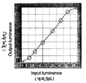
도 4b는 본 발명의 한 실시예에 따라 도 4a에 도시된 히스토그램을 가진 이미지의 콘트래스트를 개선시키는 트랜스퍼 곡선에 해당한다. 도 4a의 히스토그램은 비교적 좁은 범위에서 화소 휘도들이 집중되는 현상을 보이고 있고, 따라서, 어두운 화소와 밝은 화소들이 차지하는 총 면적이 작다는 것을 표시하기 때문에, 대부 분의 화소에 의해 점유되는 휘도 범위에서 트랜스퍼 곡선은 대략 선형을 유지한다. 또한, 트랜스퍼 곡선의 양 끝단에서 S-자형 곡선들을 이용하여 고휘도 화소들의 휘도를 증가시키고 저휘도 화소들의 휘도를 감소시킨다. 그 결과, 이미지의 전체 콘트래스트 및 동적 범위가 증가한다. 4B corresponds to a transfer curve that improves the contrast of the image with the histogram shown in FIG. 4A in accordance with one embodiment of the present invention. The histogram of FIG. 4A shows a phenomenon in which the pixel luminances are concentrated in a relatively narrow range, and thus indicates that the total area occupied by the dark pixels and the bright pixels is small, so that the transfer in the luminance range occupied by most pixels The curve remains approximately linear. In addition, S-shaped curves are used at both ends of the transfer curve to increase the luminance of the high luminance pixels and decrease the luminance of the low luminance pixels. As a result, the overall contrast and dynamic range of the image increases.
도 4d는 본 발명의 한 실시예에 따라, 도 4c에 도시된 히스토그램을 가진 이미지의 콘트래스트를 개선시키기 위한 트랜스퍼 곡선에 해당한다. 도 4a 및 도 4b에 도시된 이전의 경우와 비교하여, 도 4c의 히스토그램은 폭넓은 휘도 범위에서 화소 휘도들이 확산되어 있음을 보여주고 있으며, 따라서, 어두운 화소와 밝은 화소들이 차지하는 총 면적이 크다는 것을 알 수 있다. 따라서, 이전의 경우와는 달리, 트랜스퍼 곡선은 트랜스퍼 곡선의 양 끝단에서 약간 날씬한 S-자 곡선을 이용하여 고휘도 화소들의 휘도를 증가시키고 저휘도 화소들의 휘도를 감소시킨다. 또한 이 트랜스퍼 곡선은 두 S 곡선들 사이의 범위의 보다 평평한 기울기 변화를 포함한다. 결과적으로 이미지의 전체 콘트래스트 및 동적 범위가 증가한다.FIG. 4D corresponds to a transfer curve for improving the contrast of the image with the histogram shown in FIG. 4C, according to one embodiment of the invention. Compared to the previous case shown in FIGS. 4A and 4B, the histogram of FIG. 4C shows that the pixel luminances are diffused over a wide luminance range, and therefore, the total area occupied by dark and bright pixels is large. Able to know. Thus, unlike the previous case, the transfer curve uses a slightly slender S-shaped curve at both ends of the transfer curve to increase the brightness of the high brightness pixels and decrease the brightness of the low brightness pixels. This transfer curve also includes a flatter slope change in the range between the two S curves. As a result, the overall contrast and dynamic range of the image is increased.
도 5는 본 발명의 한 실시예에 따라 이미지의 콘트래스트를 적응성으로 개선시키는 방법을 설명하는 순서도이다. 먼저, 입력 이미지에 대한 휘도 히스토그램이 구성된다(단계 101). 대부분의 화소들이 저휘도를 가진다고 이 히스토그램이 나타내면(단계 102), 도 2b에 도시된 트랜스퍼 곡선처럼, 이미지의 중간 휘도 및 저휘도 화소들을 실질적으로 변경시키지 않으면서 이미지의 고휘도 화소들의 휘도를 증가시키는 트랜스퍼 곡선이 사용된다(단계 103). 그렇지 않을 경우, 대부분의 화소들이 고휘도를 가진다고 히스토그램이 표시하면(단계 104), 도 3b에 도시된 트랜스 퍼 곡선처럼, 이미지의 고휘도 및 중간 휘도 화소를 실질적으로 변경시키지 않으면서 이미지의 저휘도 화소들의 휘도를 감소시키는 트랜스퍼 곡선이 사용된다(단계 105). 그렇지 않을 경우, 대부분의 화소가 중간 레벨의 휘도를 가진다고 히스토그램이 표시할 경우(단계 106), 도 4b에 도시된 트랜스퍼 곡선처럼 이미지의 중가 휘도 화소들의 휘도를 실질적으로 변경시키지 않으면서 고휘도 화소들의 휘도를 증가시키고 저휘도 화소들의 휘도를 감소시키는 트랜스퍼 곡선이 사용된다(단계 107). 입력 이미지가 저휘도, 중간 휘도, 고휘도의 세 카테고리 중 어느 하나에도 들지 않을 경우, 입력 이미지 화소들의 휘도 레벨은 변경되지 않는다(단계 108).5 is a flowchart illustrating a method of adaptively improving the contrast of an image in accordance with one embodiment of the present invention. First, a luminance histogram for the input image is constructed (step 101). If the histogram indicates that most of the pixels have low brightness (step 102), as in the transfer curve shown in FIG. 2B, increasing the brightness of the high brightness pixels of the image without substantially altering the intermediate and low brightness pixels of the image The transfer curve is used (step 103). Otherwise, if the histogram indicates that most of the pixels have high brightness (step 104), then as shown in the transfer curve shown in FIG. 3B, the low brightness pixels of the image without substantially altering the high and medium luminance pixels of the image A transfer curve is used to reduce the brightness (step 105). Otherwise, if the histogram indicates that most of the pixels have intermediate levels of brightness (step 106), the luminance of the high luminance pixels without substantially changing the luminance of the intermediate luminance pixels of the image, such as the transfer curve shown in FIG. 4B. A transfer curve is used (step 107) to increase and decrease the luminance of the low luminance pixels. If the input image does not fall into any of the three categories of low luminance, intermediate luminance and high luminance, the luminance level of the input image pixels is not changed (step 108).
본 발명의 한가지 바람직한 태양은 이미지 콘트래스트가 크게 개선된다는 점이다. 출력 이미지의 평균 밝기가 조금 낮아질 수 있으나, 출력 이미지는 눈에 선명하게 보인다. 휘도를 증가시킬 때 대부분 어두운 이미지에서 밝은 화소들에 포커싱하는 것은 밝은 화소들의 과보정(over-compensation)을 가능하게 한다. 적은 수의 밝은 화소들에 의해 표현되는 비교적 적은 이미지 영역에 국한된, 세부사항의 작은 손실을 이러한 프로세스가 야기할 수 있으나, 그 결과에 따른 이미지의 콘트래스트는 개선된다. 대부분의 응용에서, 특히 이동하는 이미지(가령, 비디오 스트림)에서, 이러한 세부사항의 손실은 눈에 띌만한 것이 아니며, 따라서, 이미지 콘트래스트 개선을 위해 절충될 수 있다. 마찬가지로, 대부분 밝은 이미지에서 더 어두운 화소들의 휘도 레벨을 감소시키면, 어두운 화소들에 의해 표현되는 작은 영역에 국한된 세부사항의 작은 손실이 나타날 수 있으나, 이러한 어두운 화소의 억제 에 의해 이미지 콘트래스트를 개선시킬 수 있다. One preferred aspect of the present invention is that image contrast is greatly improved. The average brightness of the output image may be slightly lower, but the output image is clearly visible. Focusing on bright pixels in mostly dark images when increasing the brightness allows over-compensation of the bright pixels. This process can cause a small loss of detail, confined to a relatively small image area represented by a small number of bright pixels, but the contrast of the image is improved as a result. In most applications, especially in moving images (eg, video streams), the loss of these details is not noticeable and can therefore be compromised for image contrast improvement. Similarly, reducing the luminance level of darker pixels in a mostly bright image may result in a small loss of detail confined to a small area represented by dark pixels, but this suppression of dark pixels improves image contrast. You can.
본 발명의 또한가지 바람직한 태양은 상술한 트랜스퍼 함수를 이용한 결과로 발생하는 노이즈 및 윤곽 부작용에 대한 댓가가 작다는 것이다. 이 기술에 의해 노이즈 증폭 및 윤곽 부작용이 발생할 수 있으나, 이러한 부작용들은 매우 미미하다. 왜냐하면, 본원의 기술이 가장 주요한 화소 그룹들의 휘도를 실질적으로 변경시키지 않기 때문이다. 즉, 대부분 어두운 이미지에서 어두운 화소들의 휘도를 변경시키거나 대부분 밝은 이미지에서 밝은 화소들의 휘도를 변경시키지 않기 때문이다. Yet another preferred aspect of the present invention is that the cost for noise and contour side effects resulting from using the transfer function described above is small. Noise amplification and contouring side effects can be caused by this technique, but these side effects are very minor. This is because the present technology does not substantially change the luminance of the most important pixel groups. In other words, it does not change the luminance of dark pixels in most dark images or change the luminance of bright pixels in most bright images.
본 발명의 또다른 바람직한 태양은 비디오 스트림의 페이드-인 및 페이드-아웃 시 균일하지 않은 밝기 변화가 크게 감소한다는 점이다. 이 역시 상기 이유와 동일하다. 즉, 대부분 어두운 이미지에서 어두운 화소들의 휘도 레벨을 변경시키지 않으며, 대부분 밝은 이미지에서 밝은 화소들의 휘도 레벨을 변경시키지 않기 때문이다. Another preferred aspect of the present invention is that non-uniform brightness variations during the fade-in and fade-out of the video stream are greatly reduced. This is also the same reason. That is, since most of the dark images do not change the brightness level of the dark pixels, and most of the bright image does not change the brightness level of the bright pixels.
이미지들의 시퀀스에서 콘트래스트를 매끄럽게 개선시키기 위해, 트랜스퍼 함수는 가장 최근 프레임의 이미지 콘텐트를 바탕으로 하여 적응성으로 적용될 수 있다. 이 기술의 한가지 구현방식은 가장 최근의 프레임들 세트의 히스토그램을 누적시켜서, 그 평균을 연산하는 것이다. 평균 히스토그램을 바탕으로 하여, 콘트래스트 개선을 위한 적정 트랜스퍼 함수가 선택된다. 이러한 평균 기술을 구현할 때, 5~15 프레임의 버퍼가 잘 동작한다는 것이 판명되었다.In order to smoothly improve the contrast in the sequence of images, the transfer function can be adaptively applied based on the image content of the most recent frame. One implementation of this technique is to accumulate the histogram of the most recent set of frames and compute the average. Based on the mean histogram, the appropriate transfer function for the contrast improvement is chosen. When implementing this average technique, it turns out that a buffer of 5 to 15 frames works well.
디지털 디스플레이 장치에서 이미지를 디스플레이하는 내용에 관하여 발명을 기술하였다. 그러나, 디스플레이 장치의 한 영역으로 적응성 콘트래스트 개선을 제 한하는 데도 동일한 기술이 사용될 수 있다. 예를 들어, 영화의 적응성 콘트래스트 개선은 디스플레이 화면에서 수평으로 이어지는 상부 및 하부 블랙 밴드를 배제할 수 있다. 또다른 예로서, 디스플레이의 물리적 영역이나 윈도처럼, 디스플레이의 사용자-정의 영역으로 적응성 콘트래스트 개선을 제한할 수 있다. , The invention has been described with respect to the content of displaying an image in a digital display device. However, the same technique can be used to limit adaptive contrast improvement to one area of the display device. For example, the adaptive contrast improvement of a movie may exclude the upper and lower black bands running horizontally on the display screen. As another example, the adaptive contrast enhancement can be limited to a user-defined area of the display, such as a physical area of the display or a window. ,
Claims (14)
Applications Claiming Priority (4)
| Application Number | Priority Date | Filing Date | Title |
|---|---|---|---|
| US61920204P | 2004-10-15 | 2004-10-15 | |
| US60/619,202 | 2004-10-15 | ||
| US11/044,774 | 2005-01-26 | ||
| US11/044,774 US7573533B2 (en) | 2004-10-15 | 2005-01-26 | Method of generating transfer curves for adaptive contrast enhancement |
Publications (1)
| Publication Number | Publication Date |
|---|---|
| KR20060086814A true KR20060086814A (en) | 2006-08-01 |
Family
ID=35427263
Family Applications (1)
| Application Number | Title | Priority Date | Filing Date |
|---|---|---|---|
| KR1020050095270A Withdrawn KR20060086814A (en) | 2004-10-15 | 2005-10-11 | Transfer curve generation method for adaptive contrast improvement |
Country Status (6)
| Country | Link |
|---|---|
| US (1) | US7573533B2 (en) |
| EP (1) | EP1648155A3 (en) |
| JP (1) | JP2006146178A (en) |
| KR (1) | KR20060086814A (en) |
| SG (1) | SG121975A1 (en) |
| TW (1) | TW200627944A (en) |
Families Citing this family (30)
| Publication number | Priority date | Publication date | Assignee | Title |
|---|---|---|---|---|
| US20080146655A1 (en) | 2005-02-16 | 2008-06-19 | Md Bioalpha Co., Ltd. | Pharmaceutical Composition for the Treatment or Prevention of Diseases Involving Obesity, Diabetes, Metabolic Syndrome, Neuro-Degenerative Diseases and Mitochondria Dyfunction Diseases |
| JP4854252B2 (en) * | 2005-09-30 | 2012-01-18 | キヤノン株式会社 | Image processing method and image processing apparatus |
| US7684639B2 (en) * | 2005-10-20 | 2010-03-23 | Sharp Laboratories Of America, Inc. | Methods and systems for automatic digital image enhancement |
| JP4899447B2 (en) * | 2005-11-25 | 2012-03-21 | ソニー株式会社 | Self-luminous display device, light emission condition control device, light emission condition control method, and program |
| TWI315961B (en) * | 2006-03-16 | 2009-10-11 | Quanta Comp Inc | Method and apparatus for adjusting contrast of image |
| EP1840831A1 (en) * | 2006-03-31 | 2007-10-03 | Sony Deutschland Gmbh | Adaptive histogram equalization for images with strong local contrast |
| KR101313637B1 (en) * | 2006-06-09 | 2013-10-02 | 서강대학교산학협력단 | Image processing apparatus and method for contrast enhancement |
| TW200820123A (en) * | 2006-10-20 | 2008-05-01 | Primax Electronics Ltd | Method and system of generating high dynamic range image corresponding to specific scene |
| KR100791387B1 (en) * | 2006-10-25 | 2008-01-07 | 삼성전자주식회사 | Image processing method and device |
| KR100843090B1 (en) * | 2006-10-25 | 2008-07-02 | 삼성전자주식회사 | Display device and method for improving image flicker |
| US20080122857A1 (en) * | 2006-11-29 | 2008-05-29 | Chih-Lin Hsuan | Methods and devices for adjusting display characteristic of a video frame according to luminance statistics |
| TWI455085B (en) | 2007-01-26 | 2014-10-01 | Au Optronics Corp | Backlight control method for high dynamic range lcd |
| KR100855472B1 (en) * | 2007-02-07 | 2008-09-01 | 삼성전자주식회사 | Low power drive device and method |
| KR101359920B1 (en) * | 2007-04-03 | 2014-02-12 | 포항공과대학교 산학협력단 | Driving apparatus for display device, display device including the same and driving method of display device |
| US8803922B2 (en) * | 2007-05-30 | 2014-08-12 | Apple Inc. | Methods and apparatuses for increasing the apparent brightness of a display |
| US8233738B2 (en) * | 2007-07-30 | 2012-07-31 | Dolby Laboratories Licensing Corporation | Enhancing dynamic ranges of images |
| US8135230B2 (en) | 2007-07-30 | 2012-03-13 | Dolby Laboratories Licensing Corporation | Enhancing dynamic ranges of images |
| US8285071B2 (en) * | 2007-09-10 | 2012-10-09 | Himax Technologies Limited | Content-adaptive contrast improving method and apparatus for digital image |
| US8184112B2 (en) * | 2008-09-24 | 2012-05-22 | Global Oled Technology Llc | Increasing dynamic range of display output |
| US8125569B2 (en) * | 2008-12-03 | 2012-02-28 | Sony Corporation | Dynamic contrast on displays using average picture level and histogram analysis |
| KR100998015B1 (en) * | 2009-01-20 | 2010-12-08 | 삼성엘이디 주식회사 | Method for evaluating current dispersion of light emitting device and evaluation system using same |
| US8405623B2 (en) * | 2009-03-25 | 2013-03-26 | International Business Machines Corporation | Directional audio viewport for the sight impaired in virtual worlds |
| TWI408619B (en) * | 2009-11-16 | 2013-09-11 | Inst Information Industry | Image contrast enhancement apparatus and method thereof |
| KR101761413B1 (en) | 2010-11-24 | 2017-08-07 | 엘지디스플레이 주식회사 | Image quality enhancement method and display device using the same |
| US8643590B2 (en) | 2010-12-22 | 2014-02-04 | Sharp Laboratories Of America, Inc. | Ambient adaptive illumination of a liquid crystal display |
| JP5165076B2 (en) | 2011-01-31 | 2013-03-21 | シャープ株式会社 | Video display device |
| US9697593B2 (en) * | 2014-01-28 | 2017-07-04 | Ittiam Systems (P) Ltd. | System and method for tone mapping on high dynamic range images |
| CN104361566B (en) * | 2014-11-17 | 2018-08-10 | 厦门美图之家科技有限公司 | A kind of image processing method in optimization dark portion region |
| US9582866B2 (en) | 2015-03-10 | 2017-02-28 | Via Technologies, Inc. | Adaptive contrast enhancement apparatus and method |
| US10445865B1 (en) | 2018-03-27 | 2019-10-15 | Tfi Digital Media Limited | Method and apparatus for converting low dynamic range video to high dynamic range video |
Family Cites Families (20)
| Publication number | Priority date | Publication date | Assignee | Title |
|---|---|---|---|---|
| US5063607A (en) | 1988-10-24 | 1991-11-05 | Hughes Aircraft Company | Image contrast enhancement technique |
| US5414538A (en) | 1993-10-07 | 1995-05-09 | Xerox Corporation | Image-dependent exposure enhancement |
| US5450502A (en) | 1993-10-07 | 1995-09-12 | Xerox Corporation | Image-dependent luminance enhancement |
| US6463173B1 (en) | 1995-10-30 | 2002-10-08 | Hewlett-Packard Company | System and method for histogram-based image contrast enhancement |
| US5828793A (en) * | 1996-05-06 | 1998-10-27 | Massachusetts Institute Of Technology | Method and apparatus for producing digital images having extended dynamic ranges |
| KR100261214B1 (en) | 1997-02-27 | 2000-07-01 | 윤종용 | Histrogram equalization method and apparatus of a contrast expanding apparatus in image processing system |
| US5949918A (en) * | 1997-05-21 | 1999-09-07 | Sarnoff Corporation | Method and apparatus for performing image enhancement |
| EP2199973A3 (en) | 1997-06-09 | 2010-09-08 | Seiko Epson Corporation | An image processing apparatus and method, and an image evaluation device and method |
| DE69908713T2 (en) | 1998-06-22 | 2004-05-13 | Texas Instruments Inc., Dallas | Selective brightness expansion |
| US6239782B1 (en) * | 1999-01-19 | 2001-05-29 | Tektronix, Inc. | Single knob intensity control for use in digital test and measurement equipment |
| US6594388B1 (en) | 2000-05-25 | 2003-07-15 | Eastman Kodak Company | Color image reproduction of scenes with preferential color mapping and scene-dependent tone scaling |
| US6650664B1 (en) | 2001-01-19 | 2003-11-18 | The United States Of America As Represented By The Secretary Of The Air Force | Cladding-pumped fiber with helical rare-earth-doped core for fiber lasers and amplifiers |
| JP4130366B2 (en) * | 2001-04-11 | 2008-08-06 | コーニンクレッカ フィリップス エレクトロニクス エヌ ヴィ | Image signal contrast control method |
| CA2365893A1 (en) | 2001-12-21 | 2003-06-21 | Jaldi Semiconductor Corp. | System and method for dynamically enhanced colour space |
| EP1345172A1 (en) | 2002-02-26 | 2003-09-17 | Sony International (Europe) GmbH | Contrast enhancement for digital images |
| US7221807B2 (en) | 2002-03-29 | 2007-05-22 | Sharp Laboratories Of America, Inc. | Methods and systems for digital image characteristic adjustment using a neural network |
| US6778183B1 (en) | 2002-07-10 | 2004-08-17 | Genesis Microchip Inc. | Method and system for adaptive color and contrast for display devices |
| US7034843B2 (en) * | 2002-07-10 | 2006-04-25 | Genesis Microchip Inc. | Method and system for adaptive color and contrast for display devices |
| KR20040008067A (en) | 2002-07-15 | 2004-01-28 | 삼성전자주식회사 | Image enhancing circuit using corelation between frames and method therefor |
| KR20040040699A (en) | 2002-11-07 | 2004-05-13 | 삼성전자주식회사 | Apparatus and Method for compansation contrast |
-
2005
- 2005-01-26 US US11/044,774 patent/US7573533B2/en active Active
- 2005-10-04 TW TW094134727A patent/TW200627944A/en unknown
- 2005-10-07 SG SG200506563A patent/SG121975A1/en unknown
- 2005-10-11 JP JP2005296172A patent/JP2006146178A/en not_active Withdrawn
- 2005-10-11 KR KR1020050095270A patent/KR20060086814A/en not_active Withdrawn
- 2005-10-13 EP EP05256354A patent/EP1648155A3/en not_active Withdrawn
Also Published As
| Publication number | Publication date |
|---|---|
| TW200627944A (en) | 2006-08-01 |
| JP2006146178A (en) | 2006-06-08 |
| EP1648155A2 (en) | 2006-04-19 |
| US7573533B2 (en) | 2009-08-11 |
| US20060082689A1 (en) | 2006-04-20 |
| EP1648155A3 (en) | 2007-12-26 |
| SG121975A1 (en) | 2006-05-26 |
Similar Documents
| Publication | Publication Date | Title |
|---|---|---|
| KR20060086814A (en) | Transfer curve generation method for adaptive contrast improvement | |
| KR101234958B1 (en) | Adaptive contrast enhancement | |
| JP3863904B1 (en) | Liquid crystal display | |
| RU2452039C2 (en) | Video display device | |
| US8558772B2 (en) | Image display apparatus | |
| US8090198B2 (en) | Image processing apparatus, image display apparatus, and image display method | |
| US8131108B2 (en) | Method and system for dynamic contrast stretch | |
| JP4279318B2 (en) | Video display device | |
| CN102752604B (en) | Image display method and intelligent device | |
| WO2006130564A2 (en) | Method and system for automatic brightness and contrast adjustment of a video source | |
| JP2011022447A (en) | Image display device | |
| JP5221780B1 (en) | Video display device and television receiver | |
| US7483083B2 (en) | Movie enhancement | |
| JP2007049693A (en) | Liquid crystal display apparatus | |
| JP6190482B1 (en) | Display control device, display device, television receiver, display control device control method, control program, and recording medium | |
| JP5070114B2 (en) | Video display device | |
| CN1770254A (en) | Method for generating transfer curves for adaptive contrast enhancement | |
| US7729022B2 (en) | Method for processing image | |
| CN108337495B (en) | Video image dynamic contrast adjusting method and adjusting device thereof | |
| WO2012014754A1 (en) | Image display device | |
| JP5249703B2 (en) | Display device | |
| JP2007049692A (en) | Liquid crystal display apparatus | |
| JPWO2018003665A1 (en) | Image processing apparatus, image processing method, control program, and recording medium | |
| CN100388757C (en) | Method for enhancing image contrast | |
| JP2009271401A (en) | Image display apparatus |
Legal Events
| Date | Code | Title | Description |
|---|---|---|---|
| PA0109 | Patent application |
Patent event code: PA01091R01D Comment text: Patent Application Patent event date: 20051011 |
|
| PG1501 | Laying open of application | ||
| PC1203 | Withdrawal of no request for examination | ||
| WITN | Application deemed withdrawn, e.g. because no request for examination was filed or no examination fee was paid |