KR20060073451A - Prevention apparatus of earth and sand inflow by using buoyancy - Google Patents
Prevention apparatus of earth and sand inflow by using buoyancy Download PDFInfo
- Publication number
- KR20060073451A KR20060073451A KR1020050119688A KR20050119688A KR20060073451A KR 20060073451 A KR20060073451 A KR 20060073451A KR 1020050119688 A KR1020050119688 A KR 1020050119688A KR 20050119688 A KR20050119688 A KR 20050119688A KR 20060073451 A KR20060073451 A KR 20060073451A
- Authority
- KR
- South Korea
- Prior art keywords
- opening
- buoyancy
- closing plate
- sewage
- prevention device
- Prior art date
Links
Images


Classifications
-
- E—FIXED CONSTRUCTIONS
- E03—WATER SUPPLY; SEWERAGE
- E03F—SEWERS; CESSPOOLS
- E03F5/00—Sewerage structures
- E03F5/04—Gullies inlets, road sinks, floor drains with or without odour seals or sediment traps
- E03F5/041—Accessories therefor
- E03F5/0411—Devices for temporarily blocking inflow into a gully
-
- E—FIXED CONSTRUCTIONS
- E03—WATER SUPPLY; SEWERAGE
- E03F—SEWERS; CESSPOOLS
- E03F5/00—Sewerage structures
- E03F5/10—Collecting-tanks; Equalising-tanks for regulating the run-off; Laying-up basins
- E03F5/105—Accessories, e.g. flow regulators or cleaning devices
-
- E—FIXED CONSTRUCTIONS
- E03—WATER SUPPLY; SEWERAGE
- E03F—SEWERS; CESSPOOLS
- E03F5/00—Sewerage structures
- E03F5/04—Gullies inlets, road sinks, floor drains with or without odour seals or sediment traps
- E03F2005/0412—Gullies inlets, road sinks, floor drains with or without odour seals or sediment traps with means for adjusting their position with respect to the surrounding surface
- E03F2005/0413—Gullies inlets, road sinks, floor drains with or without odour seals or sediment traps with means for adjusting their position with respect to the surrounding surface for height adjustment
Abstract
본 발명은 차집관거의 토사 유입 방지장치에 관한 것으로, 보다 상세하게는 회전 개폐판의 상부에 구비된 부력통과 회전 개폐판의 하부에 구비된 물통을 통해 회전 개폐판의 개방을 단속하여 차집관거의 내부로 하수 및 토사가 유입되는 것을 방지할 수 있는 부력을 이용한 토사 유입 방지장치에 관한 것이다.The present invention relates to a sediment inflow prevention device of the tea house, more specifically to the interior of the tea house by intermittently opening the rotary opening and closing plate through the buoyancy bucket provided on the top of the rotary opening and closing plate and the water tank provided on the bottom of the rotary opening and closing plate. The present invention relates to a soil inflow preventing apparatus using buoyancy to prevent sewage and soil from entering.
본 발명에 따른 부력을 이용한 토사 유입 방지장치는 차집관거에 형성되어 있는 하수 유입홀의 둘레에 구비되어 있는 프레임과, 차집관거에 형성되어 있는 하수 유입홀의 중간에 종방향으로 구비되어 있는 지지축과, 상기 지지축의 상부에 연결 회전수단을 통해 고정되어 상기 하수 유입홀을 하수의 흐름에 따라 개폐하는 회전 개폐판으로 구성된 차집관거의 토사 유입 방지장치에 있어서, 상기 회전 개폐판의 개폐상태를 단속하기 위한 상기 회전 개폐판의 후방 상부에 다수의 부력수단이 구비됨을 특징으로 한다.The earth and sand inflow prevention apparatus using the buoyancy according to the present invention is a frame provided around the sewage inlet hole formed in the collecting pipe, the support shaft is provided in the longitudinal direction in the middle of the sewage inlet hole formed in the collecting pipe, and the support In the earth and sand inflow prevention device of the house constitution consisting of a rotary opening and closing plate fixed to the upper portion of the shaft through a connecting rotation means for opening and closing the sewage inlet hole in accordance with the flow of sewage, the rotation opening and closing for controlling the opening and closing state of the rotary opening and closing plate A plurality of buoyancy means is provided on the rear upper portion of the plate.
차집관거, 토사 유입 방지장치, 회전 개폐판, 부력수단, 무게 조절수단 House drainage, earth and sand inflow prevention device, rotary switchboard, buoyancy means, weight control means
Description
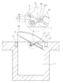
도 1은 본 발명의 제1 실시예에 따른 토사 유입 방지장치가 구비된 하수로를 나타낸 사시도.1 is a perspective view showing a sewer having a soil inflow prevention apparatus according to a first embodiment of the present invention.
도 2는 본 발명의 제1 실시예에 따른 토사 유입 방지장치를 나타낸 확대 개략 사시도.Figure 2 is an enlarged schematic perspective view showing a soil inflow prevention apparatus according to a first embodiment of the present invention.
도 3은 도 2의 A-A선 단면도.3 is a cross-sectional view taken along the line A-A of FIG.
도 4는 본 발명의 제2 실시예에 따른 토사 유입 방지장치를 나타낸 단면도.Figure 4 is a sectional view showing a soil inflow prevention apparatus according to a second embodiment of the present invention.
도 5는 본 발명의 제3 실시예에 따른 토사 유입 방지장치를 나타낸 단면도.5 is a cross-sectional view showing a soil inflow prevention apparatus according to a third embodiment of the present invention.
도 6은 종래의 토사 유입 방지장치를 나타낸 단면도.Figure 6 is a cross-sectional view showing a conventional soil inflow prevention device.
<도면의 주요 부분에 대한 부호의 설명><Explanation of symbols for the main parts of the drawings>
1 : 차집관거1: tea house
11 : 하수 유입홀 11: sewage inflow hall
111 : 프레임, 112 : 보호 덮개판, 113 : 걸림홈 111: frame, 112: protective cover plate, 113: locking groove
12 : 수평유지 스토퍼 12: leveling stopper
13 : 개방 스토퍼 13: opening stopper
131 : 탭홀 131: tap hole
14 : 전방벽 14: front wall
2 : 지지축2: support shaft
3 : 연결 회전수단3: connecting rotation means
31 : 베어링 31: Bearing
32 : 베어링 브라켓 32: bearing bracket
321 : 관통홀 321: through hole
33 : 볼트 33: Bolt
4 : 회전 개폐판4: rotating switchboard
41 : 탭홀 41: tap hole
5 : 부력수단5: buoyancy means
51 : 부력통 51: buoyancy bucket
511 : 공간부 511: space part
52 : 고정 둘레판 52: fixed perimeter plate
521 : 돌출편, 522 : 홀 521: protrusions, 522: holes
53 : 볼트 53: Bolt
6 : 무게 조절수단6: weight adjusting means
61 : 물통 61: bucket
611 : 물 주입구, 612 : 배출구, 613 : 공간부 611: water inlet, 612: outlet, 613: space part
62 : 고정 둘레판 62: fixed perimeter plate
621 : 돌출편, 622 : 홀 621: protrusion piece, 622: hole
63 : 볼트 63: Bolt
7 : 높이 조절수단7: height adjusting means
71 : 턴버클 71: turnbuckle
72 : 나선축부 72: spiral shaft portion
721 : 상부 나선축, 722 : 하부 회전 나선축 721: upper spiral axis, 722: lower rotating spiral axis
8 : 전방 개방 단속수단8: front opening control means
81 : 체인 81: chain
9 : 앙카볼트9: anchor bolt
본 발명은 차집관거의 토사 유입 방지장치에 관한 것으로, 보다 상세하게는 회전 개폐판의 상부에 구비된 부력통과 회전 개폐판의 하부에 구비된 물통을 통해 회전 개폐판의 개방을 단속하여 차집관거의 내부로 하수 및 토사가 유입되는 것을 방지할 수 있는 부력을 이용한 토사 유입 방지장치에 관한 것이다.The present invention relates to a sediment inflow prevention device of the tea house, more specifically to the interior of the tea house by intermittently opening the rotary opening and closing plate through the buoyancy bucket provided on the top of the rotary opening and closing plate and the water tank provided on the bottom of the rotary opening and closing plate. The present invention relates to a soil inflow preventing apparatus using buoyancy to prevent sewage and soil from entering.
일반적으로 하수로는 가정에서 발생되는 생활하수 및 공장이나 사업장에서 나오는 공장 폐수와, 빗물이 도로의 배수로를 통하여 모여진 하수를 배수하는 통로를 말하는 것이다.In general, sewerage refers to a passage for draining sewage generated from household sewage, factory wastewater from factories and workplaces, and rainwater collected through road drains.
특히 하수로는 배출측이 강과 연결되어 있으므로 하수가 강으로 유입되는 것이다.In particular, the sewer flows into the river because the discharge side is connected to the river.
즉 통상적으로 알려진 하수로는 배출측에 구비되어 유입되는 하수를 정화할 수 있도록 하수 처리장으로 유도하는 차집관거를 포함하고, 상기 차집관거의 후방에 구비되어 이물질등이 차집관거에 유입되지 않도록 하는 스크린으로 구성되는 것이다. In other words, the sewage is generally known to include a collecting pipe leading to the sewage treatment plant to be provided on the discharge side to purify the sewage, and is provided in the rear of the collecting pipe is composed of a screen so that foreign matters do not flow into the collecting pipe. .
그러나, 상기와 같이 구성된 종래의 하수로는, 우수로 인하여 하수의 유입량이 많을 경우에 토사가 상기 스크린을 넘어 바로 차집관거로 유입된다. 그러므로 차집관거에 토사가 쌓이게 되어 차집관거의 배수단면이 작아지게 됨은 물론, 하수 처리장으로 토사가 유입됨에 따라 하수 처리장의 정화 효율을 저하시키는 문제점을 가지고 있었다.However, in the conventional sewage system configured as described above, when there is a large amount of inflow of sewage due to rainwater, the earth and sand flows directly into the collecting cullet immediately beyond the screen. Therefore, the soil was accumulated in the drainage house, so that the drainage cross section of the drainage house was reduced, and as the soil was introduced into the sewage treatment plant, there was a problem of reducing the purification efficiency of the sewage treatment plant.
이에 상기와 같은 문제점을 해결하기 위하여 우천시 차집관거로 토사가 유입되는 것을 방지할 수 있도록 대한민국 실용신안등록출원 제 2001-1706호의 "토사 유입 방지장치"가 알려져 있다.In order to solve the problems as described above, the "earth and sand inflow prevention device" of the Republic of Korea Utility Model Registration No. 2001-1706 is known to prevent the inflow of sediment into the rain house in rainy weather.
도 6은 종래의 토사 유입 방지장치를 나타낸 단면도로서, 종래의 토사 유입 방지장치는, 하수로에 설치된 차집관거(100)의 상부에 하수 흐름 방향으로 서포트(200)를 설치하고, 상기 서포트(200)에 프레임 플레이트(300)가 회동 가능하게 회동축(400)으로 결합시키되 하수 유입쪽으로 프레임 플레이트(300)가 기울어지게 설치하는 것이다.6 is a cross-sectional view showing a conventional earth and sand inflow prevention device, the conventional earth and sand inflow prevention device, the
그리고 상기 프레임 플레이트(300)는 상부에 가해지는 수압이 높을 때 회동축(400)을 중심으로 회동하여 수평상태로 놓이게 설치하는 것이다.And the
따라서, 차집관거 상부에 프레임 플레이트를 설치하여 회동축을 중심으로 회 동되게 하되 상기 회동축은 프레임 플레이트가 하수 유입 방향을 향하여 기울어지게 일측으로 치우쳐 설치하는 것으로서, 하수가 유입되면 수압에 의해 프레임 플레이트가 닫혀 차집관거에 토사가 유입되는 것을 방지하고 유량이 줄면 프레임 플레이트의 자중에 의해 들리게 되어 하수가 차집관거를 통하여 흐르게 하는 것이다.Therefore, the frame plate is installed on the upper part of the collecting pipe, and the pivot plate is rotated about the pivot shaft, but the pivot shaft is installed to be biased toward one side so that the frame plate is inclined toward the sewage inflow direction. It is closed to prevent the inflow of sediment into the collector, and when the flow rate decreases, it is heard by the weight of the frame plate so that the sewage flows through the collector.
그러나, 상기와 같은 종래의 토사 유입 방지장치는, 우수등으로 인해 하수량이 증가하게 되면 하천의 수위가 상승되어 차집관거에 구비된 토사 유입 방지장치가 수몰되며, 이때 회전 개폐판의 개방을 단속하는 수단이 구비되어 있지 않기 때문에 상기 프레임 플레이트의 전방이 상부로 올가가게 되고 후방이 하부로 내려감으로써 차집관거의 내부로 우수와 하수 및 토사가 유입되어 하수 처리장의 수용범위를 초과하게 되는 문제점을 가지고 있었다.However, in the conventional earth and sand inflow prevention device as described above, when the amount of sewage increases due to rainwater, the water level of the river is increased so that the earth and sand inflow prevention device provided in the tea house is submerged, and means for controlling the opening of the rotary opening and closing plate. Since it is not provided with the front of the frame plate to the upper and the rear is lowered to the bottom has a problem that the rainwater and sewage and sediment flows into the interior of the collecting duct to exceed the receiving range of the sewage treatment plant.
이에 본 발명은 상기와 같은 문제점을 해결하기 위하여 개량한 것으로, 우수등으로 인해 토사 유입 방지장치가 수몰되는 경우에 회전 개폐판의 상부에 구비된 부력수단을 통해 회전 개폐판의 개방을 단속하여 차집관거의 내부로 하수 및 토사가 유입되는 것을 방지할 수 있는 부력을 이용한 토사 유입 방지장치를 제공하는데 목적이 있다.Accordingly, the present invention has been improved to solve the above problems, when the sediment inflow prevention device is submerged due to rain, etc. intercept the opening of the rotary opening and closing plate through the buoyancy means provided on the top of the rotary opening and closing plate The purpose of the present invention is to provide a sedimentation prevention device using buoyancy to prevent the inflow of sewage and sediment into the interior of the.
또한, 회전 개폐판의 하부에 구비된 무게 조절수단을 통해 물통의 무게와 부력을 조절함으로써 회전 개폐판의 개방을 단속하여 차집관거 내부로 하수 및 토사가 유입되는 것을 방지할 수 있는 부력을 이용한 토사 유입 방지장치를 제공하는 목적도 있다.In addition, by adjusting the weight and buoyancy of the water tank through the weight adjusting means provided in the lower part of the rotary opening and closing plate to control the opening of the rotary opening and closing plate, the inflow of earth and sand using buoyancy to prevent the inflow of sewage and soil into the conduit. It is also an object to provide a prevention device.
상기와 같은 목적을 달성하기 위한 본 발명은, 차집관거에 형성되어 있는 하수 유입홀의 둘레에 구비되어 있는 프레임과, 차집관거에 형성되어 있는 하수 유입홀의 중간에 종방향으로 구비되어 있는 지지축과, 상기 지지축의 상부에 연결 회전수단을 통해 고정되어 상기 하수 유입홀을 하수의 흐름에 따라 개폐하는 회전 개폐판으로 구성된 차집관거의 토사 유입 방지장치에 있어서, 상기 회전 개폐판의 개폐상태를 단속하기 위한 상기 회전 개폐판의 후방 상부에 다수의 부력수단이 구비됨을 특징으로 한다.The present invention for achieving the above object, the support shaft is provided in the longitudinal direction in the middle of the frame provided around the sewage inlet hole formed in the collecting pipe, and the sewage inlet hole formed in the collecting pipe, and the support In the earth and sand inflow prevention device of the house constitution consisting of a rotary opening and closing plate fixed to the upper portion of the shaft through a connecting rotation means for opening and closing the sewage inlet hole in accordance with the flow of sewage, the rotation opening and closing for controlling the opening and closing state of the rotary opening and closing plate A plurality of buoyancy means is provided on the rear upper portion of the plate.
이하, 본 발명의 바람직한 실시예를 첨부된 도면을 참조하여 설명하면 다음과 같다.Hereinafter, preferred embodiments of the present invention will be described with reference to the accompanying drawings.
도 1은 본 발명의 제1 실시예에 따른 토사 유입 방지장치가 구비된 하수로를 나타낸 사시도이고, 도 2는 본 발명의 제1 실시예에 따른 토사 유입 방지장치를 나타낸 확대 개략 사시도이며, 도 3은 도 2의 A-A선 단면도이다.1 is a perspective view showing a sewer having a sediment inflow prevention apparatus according to a first embodiment of the present invention, Figure 2 is an enlarged schematic perspective view of a sediment inflow prevention apparatus according to a first embodiment of the present invention, Figure 3 Is a cross-sectional view taken along the line AA of FIG.
이에 본 발명의 부력을 이용한 토사 유입 방지장치(이하," 토사 유입 방지장치"라 한다.)는 차집관거(1)에 형성되어 있는 하수 유입홀(11)의 둘레에 구비되어 있는 프레임(111)과, 차집관거(1)에 형성되어 있는 하수 유입홀(11)의 중간에 종방향으로 구비되어 있는 지지축(2)과, 상기 지지축(2)의 상부에 연결 회전수단(3)을 통해 고정되어 상기 하수 유입홀(11)을 하수의 흐름에 따라 개폐하는 회전 개폐판(4)으로 구성된 차집관거의 토사 유입 방지장치에 있어서, 상기 회전 개폐판(4)의 개폐상태를 단속하기 위한 상기 회전 개폐판(4)의 후방 상부에 다수의 부력수단(5) 이 구비됨을 특징으로 한다.Thus, the sediment inflow prevention device (hereinafter referred to as "soil inflow prevention device") using the buoyancy of the present invention and the
그리고 상기 부력수단(5)은 내부에 구비된 공간부(511)를 포함하는 부력통(51)과, 상기 부력통(51)이 이탈되지 않도록 상기 회전 개폐판(4)의 후방 상부에 구비되어 부력통(51)의 둘레를 감싸 고정하는 고정 둘레판(52)으로 구성되는 것이다.And the buoyancy means 5 is provided on the
또한 상기 회전 개폐판(4)의 후방 상부의 양측과 중앙 하부에는 다수의 탭홀(41)이 형성되어 있으며, 상기 고정 둘레판(52)의 전,후단에는 전,후방으로 돌출되게 돌출편(521)이 구비되어 있고 상기 돌출편(521)에는 상기 회전 개폐판(4)의 탭홀(41)과 상응되게 각각의 홀(522)이 형성되어 있는 것이다. 따라서 상기 회전 개폐판(4)에 상기 고정 둘레판(52)을 볼트(53) 체결함으로써 부력통(51)의 이탈을 방지하게 되는 것이다.In addition, a plurality of tab holes 41 are formed at both sides of the rear upper portion and the center lower portion of the rear opening /
한편, 상기 연결 회전수단(3)은 상기 지지축(2)의 외부에 구비되어 회전 가능하게 조립되는 베어링(31)을 포함하며 상기 회전 개폐판(4)의 하부에 형성된 탭홀(41)에 볼트(33)가 체결되도록 상부에 다수의 관통홀(321)이 구비된 베어링 브라켓(32)으로 구성되는 것이다.On the other hand, the
즉 상기 지지축(2)에 구비된 베어링(31)을 통해 하수량에 따라 회전 개폐판(4)의 회전을 원활히 할 수 있는 것이다.That is, through the bearing 31 provided on the
특히, 상기 프레임(111)에는 상기 부력통(51)의 상부를 커버하도록 보호 덮개판(112)이 더 구비되는 것이다.In particular, the
즉 상기 보호 덮개판(112)을 통해 상기 부력통(51)이 하수와 직접 충돌하는 것을 방지하며 하수가 보호 덮개판(112)의 상부로 흘러가도록 유도하는 것이다.That is, the
이하, 상기와 같이 구성된 본 발명의 제1 실시예에 따른 토사 유입 방지장치의 작동관계를 설명하면 다음과 같다. Hereinafter, the operation relationship of the soil inflow prevention apparatus according to the first embodiment of the present invention configured as described above are as follows.
먼저, 평상시에는 회전 개폐판(4)의 후방이 하부로 개방되어 있으므로 차집관거(1)의 내부로 하수가 유입되어 하수 처리장으로 원활하게 흘러가게 되는 것이다.First, since the rear of the rotary opening and
반대로, 우수로 인해 하천의 수위가 상승하게 되면, 부력통(51)의 외면과 하천 수위면이 닿게 되면서 상기 부력통(51)에 의해 발생되는 부력으로 인하여 상기 회전 개폐판(4)의 후방이 상부로 상승하게 되는 것이다.On the contrary, when the water level of the river rises due to the rain, the outer surface of the
따라서, 상기 회전 개폐판(4)의 후방이 상승하면서 회전 개폐판(4)이 수평상태가 되고, 차집관거(1)에 형성되어 있는 하수 유입홀(11)의 전,후방의 개폐상태를 단속함으로써 하수 및 토사가 차집관거(1)의 내부로 유입되는 것을 방지하게 되는 것이다. Therefore, as the rear of the
한편, 도 4는 본 발명의 제2 실시예에 따른 토사 유입 방지장치를 나타낸 단면도이다.On the other hand, Figure 4 is a cross-sectional view showing a soil inflow preventing apparatus according to a second embodiment of the present invention.
이에 본 발명에 따른 토사 유입 방지장치의 제2 실시예를 설명하기에 앞서, 본 발명의 제2 실시예에서는 후술하게 될 무게 조절수단을 제외한 타 구성은 상술한 제1 실시예와 동일함을 전제로 한다.Thus, before explaining the second embodiment of the earth and sand inflow prevention apparatus according to the present invention, in the second embodiment of the present invention, it is assumed that other configurations except for the weight adjusting means to be described later are the same as the first embodiment described above. Shall be.
도 4에 도시된 바와 같이, 회전 개폐판(4)의 전방 하부와 후방 하부에는 외측에 물 주입구(611)와 배출구(612)가 형성되며 내부에 구비된 공간부(613)를 포함 하는 다수의 물통(61)과, 상기 물통(61)이 이탈되지 않도록 상기 회전 개폐판(4)의 하부에 구비되어 물통(61)의 둘레를 감싸 고정하는 고정 둘레판(62)으로 이루어진 무게 조절수단(6)이 더 구비되는 것이다. As shown in FIG. 4, the
그리고 상기 회전 개폐판(4)의 하부에는 다수의 탭홀(41)이 형성되어 있으며, 상기 고정 둘레판(62)의 전,후단에는 전,후방으로 돌출되게 돌출편(621)이 구비되어 있고 상기 돌출편(621)에는 상기 회전 개폐판(4)의 탭홀(41)과 상응되게 각각의 홀(622)이 형성되어 있는 것이다. 따라서 상기 회전 개폐판(4)에 상기 고정 둘레판(62)을 볼트(63) 체결함으로써 물통(61)의 이탈을 방지하게 되는 것이다.In addition, a plurality of tab holes 41 are formed at a lower portion of the rotation opening and
즉, 상기 물 주입구(611)와 배출구(612)를 통해 물을 주입하거나 배출시켜 무게를 가변시킴으로써 하수량의 증감에 따라 상기 회전 개폐판(4)의 개폐상태를 조절할 수 있는 것이다. That is, by varying the weight by injecting or discharging water through the
이하, 상기와 같이 구성된 본 발명의 제2 실시예에 따른 토사 유입 방지장치의 작동관계를 설명하면 다음과 같다. Hereinafter, the operation relationship of the soil inflow prevention apparatus according to the second embodiment of the present invention configured as described above are as follows.
먼저, 평상시에는 상기 회전 개폐판(4)의 후방이 하부로 개방되어 있으므로 차집관거(1) 내부로 하수가 유입되어 하수 처리장으로 원활히 흘러가게 되는 것이다.First, since the rear of the rotary opening and closing plate (4) is usually opened to the lower side, the sewage flows into the collection conduit (1) is to flow smoothly to the sewage treatment plant.
반대로, 우수로 인해 차집관거(1)의 내부에 하수량이 많아질 경우에는, 회전 개폐판(4)의 전방 하부에 구비된 물통(61)의 외면과 하수면이 닿게 되면서 물통(61)에 의한 부력으로 인해 회전 개폐판(4)의 후방이 상부로 올라가게 되는 것이다.On the contrary, when the amount of sewage is increased in the interior of the collecting
즉 상기 회전 개폐판(4)의 후방이 상부로 올라가면서 회전 개폐판(4)이 수평상태가 되어 하수 유입홀(11)의 전,후방의 개폐상태를 단속함으로써 하수와 섞인 토사가 회전 개폐판(4)의 상부를 통과하여 하천으로 흘러가게 되는 것이다.That is, as the rear of the
따라서 하수량 증가로 인해 차집관거(1)의 내부로 하수와 섞인 토사가 유입되지 않도록 하는 것이다.Therefore, due to the increase in the amount of sewage is to prevent the inflow of sewage mixed with sewage into the interior of the tea house (1).
한편, 도 5는 본 발명의 제3 실시예에 따른 토사 유입 방지장치를 나타낸 단면도로서, 차집관거(1)의 후방벽 상부에는 지지축(2)을 통해 하수 유입홀(11)의 개폐상태를 조절하는 회전 개폐판(4)의 닫힘 상태를 단속하는 수평유지 스토퍼(12)와, 상기 차집관거(1)의 후방벽 하부에는 상기 회전 개폐판(4)의 개방상태를 단속하는 개방 스토퍼(13)가 더 구비되는 것이다.On the other hand, Figure 5 is a cross-sectional view showing a sediment inflow prevention device according to a third embodiment of the present invention, the opening and closing state of the
그리고 상기 하수 유입홀(11)둘레의 전방 상단부에는 상기 회전 개폐판(4)의 전단이 걸리도록 걸림홈(113)이 더 구비되는 것이다.And in the front upper end of the
또한 상기 수평유지 스토퍼(12)의 하부에는 상기 개방 스토퍼(13)의 높이를 조정하여 상기 회전 개폐판(4)의 개방각도를 조정할 수 있도록 높이 조절수단(7)이 더 구비되는 것이다.In addition, the height adjusting means 7 is further provided at the lower portion of the horizontal holding
이에 상기 높이 조절수단(7)은 상기 수평유지 스토퍼(12)의 하부에 수직으로 구비되어 있으며 중간에 구비된 턴버클(71)의 회전을 통해 회전되고 상기 개방 스토퍼(13)가 관통 체결되어 후방의 밀착을 통해 승강 가능하게 구비된 하부 회전 나선축(722)을 포함하는 나선축부(72)로 구성됨을 특징으로 한다.Accordingly, the height adjusting means 7 is vertically provided at the lower portion of the horizontal holding
즉 상기 나선축부(72)는 상기 수평유지 스토퍼(12)의 하부에 구비된 상부 나 선축(721)과 상기 상부 나선축(721)과 상호 이격 설치되는 하부 회전 나선축(722)으로 구성되는 것이다. 특히 상기 개방 스토퍼(13)의 상부에는 상기 하부 회전 나선축(722)과 체결되도록 탭홀(131)이 형성되는 것이다.That is, the
그리고 상기 상부 나선축(721)이 오른나사이면 상기 하부 회전 나선축(722)은 왼나사로 이루어짐으로써 상기 턴버클(71)의 회전을 통해 상기 두 나선축의 이격거리를 조정할 수 있는 것이다.When the
또한, 상기 개방 스토퍼(13)를 관통하는 하부 회전 나선축(722)의 하부가 흔들리지 않도록 전방이 상기 하부 회전 나선축(722)의 하부에 삽입되되 후방이 상기 차집관거(1)의 후방벽에 고정되도록 앙카볼트(9)를 이용하여 고정하는 것이다.In addition, the front is inserted in the lower portion of the lower
이하, 상기와 같이 구성된 높이 조절수단의 작동관계를 간략하게 설명하면 다음과 같다.Hereinafter, a brief description of the operation relationship of the height adjustment means configured as described above.
먼저, 상기 턴버클(71)을 역방향으로 조작하게 되면, 상기 상부 나선축(721)과 하부 회전 나선축(722)의 이격거리가 멀어지게 됨과 동시에 하부 회전 나선축(722)과 체결되어 있는 개방 스토퍼(13)가 하강하게 되는 것이다. First, when the
따라서 상기 하부 회전 나선축(722)에 체결되어 있는 개방 스토퍼(13)가 하강되면서 회전 개폐판(4)의 후방도 하강되어 개방각도가 커지게 되는 것이다.Therefore, as the opening
반대로, 턴버클(71)을 정방향으로 조작하게 되면, 상부 나선축(721)과 하부 회전 나선축(722)의 이격거리가 가까워짐과 동시에 하부 회전 나선축(722)과 체결되어 있는 개방 스토퍼(13)가 상승하게 되는 것이다.On the contrary, when the
따라서 상기 하부 회전 나선축(722)에 체결되어 있는 개방 스토퍼(13)가 상 승되면서 회전 개폐판(4)의 후방이 상승되어 개방각도가 작아지게 되는 것이다.Therefore, as the opening
그러므로, 상기 높이 조절수단(7)을 통해 회전 개폐판(4)의 개방상태를 조절하게 되는 개방 스토퍼의 높이를 상,하로 조절하게 됨으로써 하수가 하천으로 흘러 들어가는 시점을 조정할 수 있는 것이다.Therefore, by adjusting the height of the open stopper to adjust the opening state of the rotary opening and
한편, 상기 차집관거(1)의 전방에는 상기 회전 개폐판(4)의 개방상태를 단속하는 전방 개방 단속수단(8)이 더 구비되는 것이다.On the other hand, the front of the collecting pipe (1) is further provided with a front open control means for controlling the open state of the rotary opening and closing plate (4).
이에 상기 전방 개방 단속수단(8)은 상기 차집관거(1)의 전방벽(14)과 상기 회전 개폐판(4)의 전방 하부에 고정된 체인(81)으로 구성되는 것이다.Accordingly, the front opening control means 8 is composed of a
그리고 상기 체인(81)은 다수의 고리가 연결된 것으로 고리를 분리하여 쉽게 길이를 조정할 수가 있고, 또 마모되었을 때는 그 부분만 교환할 수 있는 것이다.In addition, the
따라서 상기 체인(81)을 통해 상기 차집관거(1)의 후방벽에 구비된 개방 스토퍼(13)의 파손으로 인해 회전 개폐판(4)이 완전하게 개방되는 것을 방지할 수 있는 것이다. Therefore, it is possible to prevent the rotary opening and
특히, 상기 전방 개방 단속수단(8)의 구성으로 체인(81)을 설명하였지만, 이에 한정하지 않고 링크장치와 같은 다양한 연결장치가 이용될 수 있음을 알리고자 한다.In particular, although the
이하, 상기와 같이 구성된 전방 개방 단속수단의 작동관계를 간략하게 설명하면 다음과 같다.Hereinafter, a brief description of the operation relationship of the front open control means configured as described above.
차집관거(1)의 내부 후방벽에 구비된 개방 스토퍼(13)는 비가 오거나 평상시 차집관거(1)의 내부에 하수가 유입되면서 수분 및 회전 개폐판(4)과의 충격으로 인 해 부식되거나 파손되는 현상이 발생된다. The opening
즉 상기 개방 스토퍼(13)가 파손될 경우에는, 개방 스토퍼(13)에 의해 개폐상태가 단속되는 회전 개폐판(4)이 완전하게 개방되는 것이다.That is, when the opening
따라서 상기 회전 개폐판(4)의 후방이 수압에 의해 처지게 되면 상기 회전 개폐판(4)의 전방이 상부로 올라가게 되는데, 이때 체인(81)을 통해 상기 회전 개폐판(4)의 전방이 완전 개방되는 것을 단속하게 되는 것이다.Therefore, when the rear of the rotary opening and
상술한 바와 같이 본 발명의 부력을 이용한 토사 유입 방지장치는 우수등으로 인해 하천이 범람하는 경우에 회전 개폐판의 상부에 구비된 부력수단을 통해 회전 개폐판의 개방을 단속하여 차집관거의 내부로 하수 및 토사가 유입되는 것을 방지할 수 있는 효과를 가지는 것이다.As described above, the earth and sand inflow prevention device using the buoyancy of the present invention is to control the opening of the rotary opening and closing plate through the buoyancy means provided in the upper part of the rotary opening and closing plate when the river overflows due to rain, etc. And it is to have an effect that can prevent the soil to flow.
또한, 회전 개폐판의 하부에 구비된 무게 조절수단을 통해 물통의 무게와 부력을 조절함으로써 회전 개폐판의 개방을 단속하여 차집관거 내부로 하수 및 토사가 유입되는 것을 방지할 수 있는 효과를 가지는 것이다.In addition, by controlling the weight and buoyancy of the water tank through the weight adjusting means provided in the lower portion of the rotation opening and closing the opening and closing of the rotation opening and closing plate to have the effect of preventing the inflow of sewage and sediment into the house.
본 발명은 첨부된 도면을 참조하여 바람직한 실시예를 중심으로 기술되었지만 당업자라면 이러한 기재로부터 본 발명의 범주를 벗어남이 없이 많은 다양한 자명한 변형이 가능하다는 것은 명백하다. 따라서 본 발명의 범주는 이러한 많은 변형의 예들을 포함하도록 기술된 청구범위에 의해서 해석되어져야 한다.While the present invention has been described with reference to the accompanying drawings, it will be apparent to those skilled in the art that many various obvious modifications are possible without departing from the scope of the invention from this description. Therefore, the scope of the invention should be construed by the claims described to include examples of many such variations.
Claims (8)
Priority Applications (1)
| Application Number | Priority Date | Filing Date | Title |
|---|---|---|---|
| KR1020050119688A KR100770359B1 (en) | 2005-12-08 | 2005-12-08 | Prevention Apparatus of Earth and sand inflow by using buoyancy |
Applications Claiming Priority (1)
| Application Number | Priority Date | Filing Date | Title |
|---|---|---|---|
| KR1020050119688A KR100770359B1 (en) | 2005-12-08 | 2005-12-08 | Prevention Apparatus of Earth and sand inflow by using buoyancy |
Publications (2)
| Publication Number | Publication Date |
|---|---|
| KR20060073451A true KR20060073451A (en) | 2006-06-28 |
| KR100770359B1 KR100770359B1 (en) | 2007-10-25 |
Family
ID=37166510
Family Applications (1)
| Application Number | Title | Priority Date | Filing Date |
|---|---|---|---|
| KR1020050119688A KR100770359B1 (en) | 2005-12-08 | 2005-12-08 | Prevention Apparatus of Earth and sand inflow by using buoyancy |
Country Status (1)
| Country | Link |
|---|---|
| KR (1) | KR100770359B1 (en) |
Cited By (4)
| Publication number | Priority date | Publication date | Assignee | Title |
|---|---|---|---|---|
| KR100774588B1 (en) * | 2007-01-18 | 2007-11-09 | 이경우 | Sewage in-draft control device having storm overflow chamber |
| KR100781790B1 (en) * | 2006-07-19 | 2007-12-04 | 이경우 | Apparatus for discharging sewage with combined sewer overflow |
| KR101119192B1 (en) * | 2009-04-30 | 2012-03-21 | 진두남 | A prevention apparatus of rain and sand inflow for storm overflow chamber |
| CN116655078A (en) * | 2023-07-31 | 2023-08-29 | 山东中治环境工程设备有限公司 | Flue gas desulfurization wastewater processor and use method thereof |
Families Citing this family (4)
| Publication number | Priority date | Publication date | Assignee | Title |
|---|---|---|---|---|
| KR101004142B1 (en) | 2008-07-08 | 2010-12-31 | 한백건설안전 주식회사 | Buoyant controller of underground concrete structure |
| KR100977492B1 (en) | 2009-11-13 | 2010-08-23 | (주) 협신기업 | Sand inflow prevention apparatus |
| KR101221721B1 (en) | 2010-02-10 | 2013-01-11 | 진두남 | A prevention apparatus of rain and sand inflow for a storm overflow chamber with a opening/closing plate an arc type |
| KR101352381B1 (en) | 2013-07-15 | 2014-01-17 | 황동언 | Sealed type switchpanel of strom overflow diverging tank for preventing soil |
Family Cites Families (4)
| Publication number | Priority date | Publication date | Assignee | Title |
|---|---|---|---|---|
| JPS56116489U (en) | 1980-02-08 | 1981-09-07 | ||
| KR200249083Y1 (en) | 2001-06-15 | 2001-10-17 | 김현철 | Sanitary pipe storm water inflow auto breaker |
| KR20020057894A (en) * | 2002-05-21 | 2002-07-12 | 이한욱 | A circuit breaker for a foul water |
| KR200381089Y1 (en) | 2004-09-18 | 2005-04-07 | 이성우 | Gathering drainage box earth sand inflow shutoff apparatus |
-
2005
- 2005-12-08 KR KR1020050119688A patent/KR100770359B1/en active IP Right Grant
Cited By (5)
| Publication number | Priority date | Publication date | Assignee | Title |
|---|---|---|---|---|
| KR100781790B1 (en) * | 2006-07-19 | 2007-12-04 | 이경우 | Apparatus for discharging sewage with combined sewer overflow |
| KR100774588B1 (en) * | 2007-01-18 | 2007-11-09 | 이경우 | Sewage in-draft control device having storm overflow chamber |
| KR101119192B1 (en) * | 2009-04-30 | 2012-03-21 | 진두남 | A prevention apparatus of rain and sand inflow for storm overflow chamber |
| CN116655078A (en) * | 2023-07-31 | 2023-08-29 | 山东中治环境工程设备有限公司 | Flue gas desulfurization wastewater processor and use method thereof |
| CN116655078B (en) * | 2023-07-31 | 2023-09-26 | 山东中治环境工程设备有限公司 | Flue gas desulfurization wastewater processor and use method thereof |
Also Published As
| Publication number | Publication date |
|---|---|
| KR100770359B1 (en) | 2007-10-25 |
Similar Documents
| Publication | Publication Date | Title |
|---|---|---|
| KR100770359B1 (en) | Prevention Apparatus of Earth and sand inflow by using buoyancy | |
| KR100774588B1 (en) | Sewage in-draft control device having storm overflow chamber | |
| US8939169B2 (en) | Unpowered apparatus for preventing backflow | |
| KR100980234B1 (en) | Gathering drainage box of Earth and sand inflowPrevention apparatus | |
| JPH06510097A (en) | Method and device for delayed drainage of precipitation or rainwater from roofs and surfaces with damming capacity | |
| KR100969488B1 (en) | A prevention apparatus of rain and sand inflow for opening and closing point in time adjustable storm overflow chamber | |
| KR101016159B1 (en) | A prevention apparatus of rain and sand inflow for a storm overflow chamber | |
| KR101384724B1 (en) | Groundwater treatment system of rainwater and construction methode thereof | |
| KR100711855B1 (en) | Gathering drainage box of Earth and sand inflow Prevention apparatus | |
| KR101295928B1 (en) | Rain collecting well for preventing counterflow and increasing drainage | |
| KR101106890B1 (en) | a Prevention apparatus of rain inflow for storm overflow chamber | |
| KR100648265B1 (en) | Gathering drainage box earth sand inflow shutoff apparatus | |
| KR101296566B1 (en) | A prevention apparatus of rain and sand inflow for a manhole | |
| KR100781790B1 (en) | Apparatus for discharging sewage with combined sewer overflow | |
| KR101221721B1 (en) | A prevention apparatus of rain and sand inflow for a storm overflow chamber with a opening/closing plate an arc type | |
| KR200381089Y1 (en) | Gathering drainage box earth sand inflow shutoff apparatus | |
| KR20100120472A (en) | Gathering drainage box of earth and sand inflowprevention apparatus | |
| KR100711853B1 (en) | Gathering drainage box of Earth and sand inflow Prevention apparatus | |
| KR101132847B1 (en) | a Prevention apparatus of rain and sand inflow with a buoyancy chamber | |
| KR101356852B1 (en) | Apparatus for preventing from the inflow of sand and rain | |
| KR100654402B1 (en) | Manhole having multitude structure | |
| KR100632438B1 (en) | Device for controlling flow in regulators | |
| KR200234791Y1 (en) | Protect apparatus of earth and sand's inflow | |
| KR101151164B1 (en) | A prevention apparatus of rain and sand inflow for a storm overflow chamber | |
| KR200381745Y1 (en) | Gathering drainage box earth sand inflow shutoff apparatus |
Legal Events
| Date | Code | Title | Description |
|---|---|---|---|
| A201 | Request for examination | ||
| G15R | Request for early opening | ||
| E902 | Notification of reason for refusal | ||
| E90F | Notification of reason for final refusal | ||
| E701 | Decision to grant or registration of patent right | ||
| GRNT | Written decision to grant | ||
| G170 | Publication of correction | ||
| FPAY | Annual fee payment |
Payment date: 20121019 Year of fee payment: 6 |
|
| FPAY | Annual fee payment |
Payment date: 20131021 Year of fee payment: 7 |
|
| FPAY | Annual fee payment |
Payment date: 20140808 Year of fee payment: 8 |
|
| FPAY | Annual fee payment |
Payment date: 20150918 Year of fee payment: 9 |
|
| FPAY | Annual fee payment |
Payment date: 20170410 Year of fee payment: 10 |
|
| FPAY | Annual fee payment |
Payment date: 20180417 Year of fee payment: 11 |
|
| FPAY | Annual fee payment |
Payment date: 20191114 Year of fee payment: 13 |