KR20060045460A - Digital camera capable of brightness and contrast control - Google Patents
Digital camera capable of brightness and contrast control Download PDFInfo
- Publication number
- KR20060045460A KR20060045460A KR1020050027897A KR20050027897A KR20060045460A KR 20060045460 A KR20060045460 A KR 20060045460A KR 1020050027897 A KR1020050027897 A KR 1020050027897A KR 20050027897 A KR20050027897 A KR 20050027897A KR 20060045460 A KR20060045460 A KR 20060045460A
- Authority
- KR
- South Korea
- Prior art keywords
- brightness
- lcd panel
- contrast
- signal
- control
- Prior art date
Links
Images


Classifications
-
- G—PHYSICS
- G09—EDUCATION; CRYPTOGRAPHY; DISPLAY; ADVERTISING; SEALS
- G09G—ARRANGEMENTS OR CIRCUITS FOR CONTROL OF INDICATING DEVICES USING STATIC MEANS TO PRESENT VARIABLE INFORMATION
- G09G3/00—Control arrangements or circuits, of interest only in connection with visual indicators other than cathode-ray tubes
- G09G3/20—Control arrangements or circuits, of interest only in connection with visual indicators other than cathode-ray tubes for presentation of an assembly of a number of characters, e.g. a page, by composing the assembly by combination of individual elements arranged in a matrix no fixed position being assigned to or needed to be assigned to the individual characters or partial characters
- G09G3/34—Control arrangements or circuits, of interest only in connection with visual indicators other than cathode-ray tubes for presentation of an assembly of a number of characters, e.g. a page, by composing the assembly by combination of individual elements arranged in a matrix no fixed position being assigned to or needed to be assigned to the individual characters or partial characters by control of light from an independent source
- G09G3/36—Control arrangements or circuits, of interest only in connection with visual indicators other than cathode-ray tubes for presentation of an assembly of a number of characters, e.g. a page, by composing the assembly by combination of individual elements arranged in a matrix no fixed position being assigned to or needed to be assigned to the individual characters or partial characters by control of light from an independent source using liquid crystals
-
- H—ELECTRICITY
- H04—ELECTRIC COMMUNICATION TECHNIQUE
- H04N—PICTORIAL COMMUNICATION, e.g. TELEVISION
- H04N23/00—Cameras or camera modules comprising electronic image sensors; Control thereof
- H04N23/70—Circuitry for compensating brightness variation in the scene
-
- H—ELECTRICITY
- H04—ELECTRIC COMMUNICATION TECHNIQUE
- H04N—PICTORIAL COMMUNICATION, e.g. TELEVISION
- H04N23/00—Cameras or camera modules comprising electronic image sensors; Control thereof
- H04N23/60—Control of cameras or camera modules
- H04N23/63—Control of cameras or camera modules by using electronic viewfinders
-
- H—ELECTRICITY
- H04—ELECTRIC COMMUNICATION TECHNIQUE
- H04N—PICTORIAL COMMUNICATION, e.g. TELEVISION
- H04N23/00—Cameras or camera modules comprising electronic image sensors; Control thereof
- H04N23/60—Control of cameras or camera modules
- H04N23/65—Control of camera operation in relation to power supply
- H04N23/651—Control of camera operation in relation to power supply for reducing power consumption by affecting camera operations, e.g. sleep mode, hibernation mode or power off of selective parts of the camera
-
- G—PHYSICS
- G09—EDUCATION; CRYPTOGRAPHY; DISPLAY; ADVERTISING; SEALS
- G09G—ARRANGEMENTS OR CIRCUITS FOR CONTROL OF INDICATING DEVICES USING STATIC MEANS TO PRESENT VARIABLE INFORMATION
- G09G2320/00—Control of display operating conditions
- G09G2320/06—Adjustment of display parameters
- G09G2320/0606—Manual adjustment
-
- G—PHYSICS
- G09—EDUCATION; CRYPTOGRAPHY; DISPLAY; ADVERTISING; SEALS
- G09G—ARRANGEMENTS OR CIRCUITS FOR CONTROL OF INDICATING DEVICES USING STATIC MEANS TO PRESENT VARIABLE INFORMATION
- G09G2320/00—Control of display operating conditions
- G09G2320/06—Adjustment of display parameters
- G09G2320/0626—Adjustment of display parameters for control of overall brightness
-
- G—PHYSICS
- G09—EDUCATION; CRYPTOGRAPHY; DISPLAY; ADVERTISING; SEALS
- G09G—ARRANGEMENTS OR CIRCUITS FOR CONTROL OF INDICATING DEVICES USING STATIC MEANS TO PRESENT VARIABLE INFORMATION
- G09G2320/00—Control of display operating conditions
- G09G2320/06—Adjustment of display parameters
- G09G2320/066—Adjustment of display parameters for control of contrast
-
- G—PHYSICS
- G09—EDUCATION; CRYPTOGRAPHY; DISPLAY; ADVERTISING; SEALS
- G09G—ARRANGEMENTS OR CIRCUITS FOR CONTROL OF INDICATING DEVICES USING STATIC MEANS TO PRESENT VARIABLE INFORMATION
- G09G2330/00—Aspects of power supply; Aspects of display protection and defect management
- G09G2330/02—Details of power systems and of start or stop of display operation
- G09G2330/021—Power management, e.g. power saving
-
- G—PHYSICS
- G09—EDUCATION; CRYPTOGRAPHY; DISPLAY; ADVERTISING; SEALS
- G09G—ARRANGEMENTS OR CIRCUITS FOR CONTROL OF INDICATING DEVICES USING STATIC MEANS TO PRESENT VARIABLE INFORMATION
- G09G2360/00—Aspects of the architecture of display systems
- G09G2360/14—Detecting light within display terminals, e.g. using a single or a plurality of photosensors
- G09G2360/144—Detecting light within display terminals, e.g. using a single or a plurality of photosensors the light being ambient light
-
- H—ELECTRICITY
- H04—ELECTRIC COMMUNICATION TECHNIQUE
- H04N—PICTORIAL COMMUNICATION, e.g. TELEVISION
- H04N2101/00—Still video cameras
Abstract
본 발명의 일 실시예에 따른 방법은 디지탈 카메라에 포함되는 LCD 패널의 근처에서 주변 밝기 신호를 생성하는 과정을 포함한다. 방법은 역시 LCD 패널 근처에서 적어도 부분적으로 주변 밝기 신호에 따라 LCD 패널의 휘도 및 콘트라스트 중 적어도 어느 하나를 제어하는 과정을 포함할 수 있다. 물론, 많은 대안책들, 변형들 및 수정안들이 이 실시예를 벗어남 없이 가능할 것이다.The method according to an embodiment of the present invention includes generating an ambient brightness signal in the vicinity of the LCD panel included in the digital camera. The method may also include controlling at least one of the brightness and contrast of the LCD panel in accordance with the ambient brightness signal at least partially near the LCD panel. Of course, many alternatives, modifications, and variations will be possible without departing from this embodiment.
디지탈 카메라, LCD 패널, 휘도, 콘트라스트 Digital Camera, LCD Panel, Brightness, Contrast
Description
청구된 주요 사안들에 대한 실시예의 양상 및 장점들은 다음의 상세하게 설명되는 명세서 및 도면들을 참고하여 명확해질 것이며, 여기서 같은 참조 부호는 같은 부분을 설명하고 있다:Aspects and advantages of an embodiment of the claimed subject matter will become apparent with reference to the following detailed description and drawings, wherein like reference numerals describe the same parts:
도 1은 시스템 실시예를 도시한 도면;1 illustrates a system embodiment;
도 2는 또 다른 시스템 실시예를 도시한 도면; 및2 illustrates another system embodiment; And
도 3은 일실시예에 따른 예시적 동작 특성을 도시한 도면.3 illustrates exemplary operating characteristics in accordance with one embodiment.
비록 아래에서는 예시적인 실시 예들을 참고하여 본 발명을 상세히 설명하지만, 많은 대안 예들, 수정 예들 및 변형 예들이 당업자에게 명백할 것이다. 따라서, 청구하는 본 발명은 폭넓게 이해될 수 있으며, 본 발명의 청구범위에 의해서 그 범위가 정하여 진다.Although the present invention is described in detail below with reference to exemplary embodiments, many alternatives, modifications and variations will be apparent to those skilled in the art. Accordingly, the claimed invention can be broadly understood and its scope is defined by the claims of the invention.
본 발명은 휘도(brightness) 및 콘트라스트(contrast)를 제어할 수 있는 디지탈 카메라에 관한 것이다.The present invention relates to a digital camera capable of controlling brightness and contrast.
소형 전자 장치들은 주로 배터리에 의해 전력을 공급받는다. 시스템의 전력 소모는 배터리 수명에 영향을 미칠 것이다. 디지털 카메라(DSC)의 경우에 있어서, 전력 소모는 카메라에 의해 얼마나 많은 사진들을 촬영할 수 있는 지에 제한 요소가 되며, 이러한 점이 디지탈 카메라 설계를 위한 주요 변수 중 하나이다. 디지탈 카메라의 전체 전력 소모를 감소시키기 위한 많은 전력 운용 기술들이 사용되고 있다. 예를 들어, 직류/직류(DC/DC) 컨버터의 효율을 개선하거나 불필요한 회로에 대한 전력소모를 없앨 수 있을 것이다. 디지탈 카메라의 LCD(Liquid Crystal Display) 패널은 디지탈 카메라가 온(ON) 상태일 때, 거의 항상 구동된다. 예를 들어, 이는 사용자가 사진을 촬영할 필요가 있을 때 뷰 파인더로써 사용된다. 또한, 사용자가 디지탈 카메라로 촬영한 사진을 다시 볼 때에도 필요하다. 동시에 LCD 패널은 전체 전력 소모의 약 15%를 소모하고 있다. 종래의 디지탈 카메라는 주변 밝기 상태에 따른 LCD 패널에 대한 전력을 조절하는 것으로 전력 소모를 감소시키기 위한 메카니즘을 포함하지 않는다.Small electronic devices are mainly powered by batteries. The power consumption of the system will affect the battery life. In the case of a digital camera (DSC), power consumption is a limiting factor on how many pictures can be taken by the camera, which is one of the key variables for digital camera design. Many power management techniques are used to reduce the overall power consumption of digital cameras. For example, it may be possible to improve the efficiency of a DC / DC converter or to eliminate power consumption for unnecessary circuits. The liquid crystal display (LCD) panel of a digital camera is almost always driven when the digital camera is in an ON state. For example, it is used as a view finder when the user needs to take a picture. It is also necessary when the user views the picture taken by the digital camera again. At the same time, LCD panels consume about 15% of the total power consumption. Conventional digital cameras do not include a mechanism for reducing power consumption by adjusting power to the LCD panel according to ambient brightness conditions.
상기와 같은 문제점을 해결하기 위하여 안출된 것으로써 본 발명의 목적은 디지탈 카메라에 포함되는 LCD 패널 디스플레이를 위한 밝기/콘트라스트 제어 시스템을 제공하는데 있다.SUMMARY OF THE INVENTION An object of the present invention is to provide a brightness / contrast control system for an LCD panel display included in a digital camera.
이하 본 발명의 바람직한 실시예를 첨부된 도면을 참조하여 상세히 설명하면 다음과 같다. 그리고, 본 발명의 요지를 불필요하게 흐릴 수 있다고 판단되는 경우 그 상세한 설명을 생략한다.Hereinafter, exemplary embodiments of the present invention will be described in detail with reference to the accompanying drawings. In the case where it is determined that the gist of the present invention may be unnecessarily obscured, the detailed description thereof will be omitted.
도 1은 본 발명이 청구한 대상에 대한 시스템(100) 실시예를 도시하고 있다. 시스템(100)은 일반적으로 디지탈 카메라(114)를 포함하고 있다. 디지탈 카메라(114)는 스틸 영상 카메라이거나 디지탈 비디오 카메라일 수 있다. 본 실시예에서 제공되는 바와 같은 디지탈 카메라(114)는 전원 버튼(102), 동작 모드 선택 버튼(104), 사용자 인터페이스 제어 버튼(106), 광학식 뷰 파인더(108) 및 LCD 패널(110)을 포함할 것이다. 본 실시예에서는 조도 센서(light sensor)(112)가 포함될 것이다. 조도 센서는 디지탈 카메라상의 소정의 위치에 설치될 것이며, 본 실시예에서 조도 센서(112)는 LCD 패널(110) 근처에 위치될 수 있다. 조도 센서는 주변 밝기 상태를 나타내는 신호(signal indicative)를 생성할 수 있을 것이다. 그러한 신호는 하기에 좀더 상세하게 설명되는 바와 같이, LCD 패널(110)의 휘도(brightness)를 조절하기 위하여 디지탈 카메라내에 포함되는 회로에 의해 사용될 수 있다.1 illustrates a
상기 개시된 디지탈 카메라(114)의 어떤 구성 요소들은 종래의, 일반적이고 또는/및 통상적인 구성 요소들을 포함하고 있다는 것을 고려하여 이해하여야 한다. 예를 들어, 전원 버튼(102)은 디지탈 카메라에 제공될 수 있는 종래의 스위치로 나 타낼 수 있을 것이다. 마찬가지로, 동작 모드 선택 버튼(104) 및/또는 사용자 인터페이스 제어 버튼(106) 및/또는 광학식 뷰 파인더(108) 및/또는 LCD 패널(110)은 종래의 형상으로 나타낼 수 있다. 대안적으로, 다른 실시예에서는 이러한 구성 요소들의 전부 또는 일부는 본 명세서에서 기술하고 있는 사상에 벗어남이 없이 최근에 이용 가능하거나 이후에 개발되는 동등한 구조, 및/또는 동등한 기능적 대상(펌웨어 내에서 수행되는 것과 같은)들로 대체될 수 있다. 더욱이, 본 명세서는 폭넓은 범위이며, 동등한 대상물들이 하기의 어떤 실시예에서 사용될 수 있음을 이해해야할 것이다.It is to be understood that certain components of the
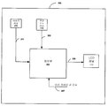
도 2는 본 발명이 청구한 대상에 대한 또 다른 시스템(200) 실시예를 도시하고 있다. 이 실시예는 디지탈 카메라와 관련된 모든 또는 일부의 동작 기능을 수행할 수 있는 제어 회로(202)(이하 "제어부"라 함)를 구비하는 디지탈 카메라를 포함할 수 있다. 여기에 기술된 바와 같은 "회로("circuitry)"는 예를 들어, 단일 또는 복합적인, 배선이 접속되는 회로, 프로그램할 수 있는 회로, 단일 기계 회로, 및/또는 프로그램 회로에 의해 수행되는 명령(instruction)들을 저장하는 펌웨어를 포함할 수 있다. 제어부(202)는 예를 들어, ASIC(Application Specific Integrated Circuit), MIC(Microprocessor Integrated Circuit) 및/또는 DSP(Digital Signal Processing unit) 집적 회로를 포함할 수 있다. 여기의 어떤 실시예에서 사용되는 "집적 회로"는 반도체 집적 회로칩과 같은 반도체 장치 및/또는 마이크로 전자 장치(microelectronic device)를 의미한다. 물론, 디지탈 카메라(114)는 역시 하나 또는 그 이상의 다음과 같은 형태의 메모리(미도시 됨)를 포함할 수 있다: 반도체 펌웨어 메모리, 프로그램 메모리, 비휘발성 메모리, ROM(Read Only Memory), 전기적 프로그램 메모리, RAM(Random Access Memory), 플래시 메모리, 자기 디스크 메모리 및/또는 광 디스크 메모리등. 추가적으로나 대안적으로, 메모리는 다른 및/또는 이후에 개발되는 형태의 컴퓨터 독취 메모리를 포함할 수 있다. 기계 독취가능한 펌웨어 프로그램 명령들이 메모리에 저장될 수 있다. 하기에 기술된 바와 같이, 이러한 명령들은 제어부(202)에 의해 액세스되고 수행되며, 이러한 명령들은 이하에서 제어부(202)에 의해 수행되는 것으로 기술된 바와 같이, 제어부(202) 기능 동작으로 나타난다.2 illustrates another embodiment of a
이 실시예에서, 제어부(202)는 여기에 기술된 방식으로, LCD 패널(110)의 휘도(brightness)를 조절하기 위한 하나 또는 그 이상의 신호들을 생성할 수 있다. 주변 조도 센서(112)는 주변 밝기 상태를 나타내는 및/또는 주변 발기 상태에 비례하는 신호(203)를 생성할 수 있다. 이러한 주변 밝기 상태는 (도 1을 참고하여 상술한 바와 같이) LCD 패널의 근처의 주변 밝기 상태이거나, 디지탈 카메라(114)의 동작 환경에 대한 일반적인 주변 밝기 상태일 수 있다. 제어부(202)는 신호 203을 수신하여 제어 신호 205를 생성할 수 있다. 제어 신호(205)는 LCD 패널(110)의 휘도를 조절할 수 있다. 여기의 어떤 실시예에서 사용되는 "근처(vicinity)"라는 용어는 서로 근처에 있는 것으로 기술되어 있는 구성 부품(구성 요소)들 간의 어떤 특별한 관련을 의미하기 위하여 폭넓게 해석될 수 있다. 따라서, 예를 들어, 주변조도 센서(112)는 디지탈 카메라의 어떤 부분(예를 들어, 도 1에 도시된 바와 같은 디지탈 카메라 하우징의 어떤 부분)에 배치될 수 있으며, LCD 패널의 근처에 있는 것으로 해석될 수 있다.In this embodiment, the
LCD 패널(110)은 예를 들어, LCD 패널을 밝힐 수 있는 WLED(White Light Emitting Diode)를 포함할 수 있다. 대안적으로, LCD 패널은 형광 발광 시스템 및/또는 패널을 밝히기 위한 다른 광원을 포함할 수 있다. 이 실시예에서는, 제어 신호(205)는 LCD 패널에 의해 생성된 광량을 제어할 수 있다. 제어 신호(205)는 광으로 이송되는 총전력을 조절할 수 있다. 예를 들어, 제어 신호(205)는 LCD 패널을 밝히는 WLED로 조절가능한 전류를 공급할 수 있다. 대안적으로, 카메라(114)는 광에 DC 신호를 생성할 수 있는 DC/DC 컨버터 회로를 포함할 수 있으며, 제어 신호는 DC/DC 컨버터 회로의 출력을 제어할 수 있는(예를 들어, PWM 신호의 펄스폭을 제어하는 것으로) PWM(Pulse Width Modulated) 신호를 포함할 수 있다.The
조도 센서(112)는 주변 밝기 상태를 나타내거나 주변 밝기 상태에 비례하는 신호(203)를 생성할 수 있는 포토 다이오드, (바이폴라 또는 MOS 형태의)포토 트랜지스터, 포토 셀 및/또는 포토-저항 타입 조도 센서를 포함할 수 있다.The
이 실시예에 있어서, 제어부(202)는 신호 203을 수신하여 주변 밝기 상태에 근거하여 램프의 휘도를 조절하기 위한 제어 신호(205)를 생성한다. 부가적으로 또는 대안적으로, 제어부(202)는 주변 밝기 상태에 근거하여 LCD 패널(110)의 콘트라스트(contrast)를 조절하기 위한 신호(205)를 생성할 수 있다. 따라서, 예를 들어, LCD 패널(114) 근처의 주변 밝기가 증가되면, 제어부(202)는 패널(114)의 휘도를 증가시키기 위한 제어 신호(205)를 생성할 것이다. 반대로, LCD 패널(114) 근처의 주변 밝기가 감소되면, 제어부(202)는 패널(114)의 휘도를 감소시키기 위한 제어 신호(205)를 생성할 것이다. 따라서, 신호 203은 피드백(feedback) 신호로써 제어부(202)에 의해 사용될 것이다.In this embodiment, the
제어부(202)는 또한 미리 정해진 값 신호(preset value signal)(207)을 수신할 수도 있다. 신호 207은 카메라(114) 사용자가 제공할 수 있는, 미리 정해진 LCD 패널의 휘도 수치를 나타낼 것이다. 이 실시예에서는, 제어부(202)는 또 다른 피드백 입력 신호로써 신호 203을 수신할 수 있다. 신호 203은 제어부(202)를 위한 한계 레벨(threshold level)을 정하는 명령 신호로써 동작할 것이다. 따라서, 예를 들어, 미리 정해진 값 신호(207)는 바람직한 휘도 수치를 정하기 위하여 제어부(202)에 의하여 사용될 것이며, 다음에는 제어부(202)가 신호 203을 지우게 하거나 또는 휘도 변화 범위를 제한하기 위한 한계값을 제공하며, 따라서 사용자가 바람직한 휘도 레벨에서 패널 디스플레이를 조작할 수 있도록 할 것이다. 대안적으로, 본 실시예를 벗어나지 않는 범위에서 신호 207은 "최고 한도" 또는 "최저 한도"로써 동작할 것이다. 이 실시예에 있어서, 제어부(202)는 패널 휘도가 신호 207에 의해 지시되는 휘도 레벨을 초과하거나 아래로 떨어지지 않도록 신호 207과 신호 203을 비교할 수 있다.The
미리 정해진 값 신호(207)는, 예를 들어, 카메라(114)의 외부 하우징에 위치되는 가변 저항 장치(예를 들어, 사용자에 의해 제어되는 전위차계)에 의해 생성될 수 있다. 대안적으로, 사용자 입력 회로는 선택 버튼 동작 및/또는 메뉴 선택을 포함하는 특성화된 컴퓨터 조작을 포함할 수 있다. 이러한 구현방법은, 예를 들어, 카메라에 의해 수행되는 소프트웨어 및/또는 펌웨어 명령을 포함한다. 대안적으로, 미리 정해진 값 신호(207)는 미리 프로그래밍된(또는 사용자가 프로그래밍할 수 있는) 미리 정해진 값 신호(207)를 생성할 수 있는 미리 프로그래밍되거나 사용자가 프로그래밍할 수 있는 회로에 의해 생성될 수 있다.The
도 3은 일 실시예에 따른 예시적인 동작 특성의 그래프(300)를 도시하고 있다. 도 3에 있어서, 도 1 및 도 2에 도시된 시스템(100, 200)은 명확성을 위하여 생략되나, 도 3을 참조하여 기술되는 동작 특성은 도 1 및 도 2에 도시된 실시예, 또는 본 실시예를 벗어나지 않는 범주내에서 다른 시스템을 포함하는 방식으로 구현될 수 있음을 이해해야 한다.3 illustrates a
x축(302)은 주변 밝기 강도(세기)를 나타내며 y축(304)는 LCD 패널(114)의 휘도 및/또는 콘트라스트를 나타낸다. 이 실시예에서, 조도 센서(112)는 실질적으로 수직인 라인 306에 의해 표시되는 바와 같은 최대 감지 밝기 강도(세기)를 갖는다. 또한, LCD 패널(114)은 점근선 308에 의해 나타나는 바와 같이, 최대 가시(viewable) 휘도 및/또는 콘트라스트 레벨을 가질 수 있으며, 점근선 310에 의해 나타나는 바와 같이, 최소 가시 휘도 및/또는 콘트라스트 레벨을 가질 수 있다. 동작중에, 제어부(202)는 센서(112)로부터 감지되는 주변 밝기에 따른 LCD 패널(114)의 휘도/콘트라스트를 조절할 수 있다. 이러한 동작은 레벨 310과 308 사이의 선형 관계 312로써 도시된다. 물론, 제어부(202)는 주변 밝기 레벨과 LCD 패널 휘도/콘트라스트 사이의, 예를 들어 로그 함수, 2차방정식 및/또는 비선형 관계 등과 같은 다른 관계를 생성할 수 있다.The
이 실시예에 있어서, 주변 밝기 레벨이 최대 가시 휘도 및/또는 콘트라스트 레벨 308과 같거나 초과한다면, 제어부(202)는 LCD 패널의 전력을 하강시키는 제어 신호(205)를 생성할 것이다. 따라서, 배터리 전력은 사용자가 LCD 패널을 볼 수 없는 상황에서는 LCD 패널(110)의 전력을 끊음으로써 절약될 수 있다.In this embodiment, if the ambient brightness level is equal to or exceeds the maximum visible brightness and / or
대안적인 실시예에서는, 도 2의 시스템 실시예를 다시 참고하여 설명하면, 디지탈 카메라(114)는 디지탈 카메라내에 포함되는 렌즈(미도시 됨)에 의해 캡쳐링되는 화상의 밝기 특성을 감지할 수 있는 이미지 센서(210)[예를 들어, CCD(Charge-Coupled Device) 또는 CMOS 소자]를 역시 포함할 수 있다. 이미지 센서(210)는 렌즈에 의해 캡쳐링된 이미지를 나타내는 신호(211)를 생성할 수 있다. 제어부(202)는 LCD 디스플레이(110)상의 이미지 센서(210)에 의해 캡쳐링된 이미지를 디스플레이 할 수 있다. 신호 211은 카메라 렌즈에 입사되는 광의 밝기 특성을 나타내는 신호일 수 있다. 제어부(202)는 렌즈에 입사되는 광의 밝기 특성을 나타내는 신호를 수신할 수 있으며, 더욱이 이 신호를 LCD 패널의 휘도 및/또는 콘트라스트를 제어하기 위한 부가적인 피드백 정보로 사용할 수 있다. 예를 들어, 신호 211이 이미지를 수반한다면, 제어부(202)는 적어도 부분적으로 신호 211의 값에 근거하여 LCD의 휘도 및/또는 콘트라스트를 조절할 수 있다.In an alternative embodiment, referring again to the system embodiment of FIG. 2, the
따라서, 결론적으로, 여기의 적어도 하나의 실시예는 디지탈 카메라에 포함되는 LCD 패널 디스플레이를 위한 밝기/콘트라스트 제어 시스템을 제공한다. 시스템은 LCD 패널과 LCD 패널 주변 밝기를 나타내는 신호를 생성하는 광학 센서를 포함한다. 시스템은 역시 적어도 부분적으로 LCD 패널 주변 밝기를 나타내는 신호에 따른 LCD 패널의 휘도 및 콘트라스트 중 적어도 어느 하나를 제어하기 위하여 전력 및 콘트라스트 신호 중 적어도 어느 하나를 생성할 수 있다. 바람직하게는, 여기의 적어도 어느 하나의 실시예에 따른 디지탈 카메라는 제어부로 제공되는 피드백 정보를 억기 위하여 주변 밝기 정보를 사용할 수 있다. 부가적으로, 여기의 적어도 어느 하나의 실시예에 따른 디지탈 카메라는 주변 밝기 상태에 따라 LCD 패널의 휘도 및/또는 콘트라스트를 자동으로 조절할 수 있다. 바람직하게는, 이러한 양상들은 이러한 실시예들에 따른 디지탈 카메라가 종래에 비하여 강화된 다목적 및 유용성을 제시할 수 있는 것이며, 종래 기술에 비하여 여기에 기술된 휘도 및/또는 콘트라스트 제어 시스템을 사용하는 것으로 설계 비용 및 전력 요구가 감소될 수 있다. 더욱이, 본 명세서에는 디지탈 카메라를 참조하여 특정한 유용성(기능)을 기술하였지만, 본 발명은 LCD 디스플레이의 휘도 및/또는 콘트라스트 제어가 요구되는 소형 또는 휴대용 전자 장치에서도 유용성을 찾을 수 있다는 것이 동등하게 숙고되어야 한다.Thus, in conclusion, at least one embodiment herein provides a brightness / contrast control system for an LCD panel display included in a digital camera. The system includes an LCD panel and an optical sensor that generates a signal indicative of the brightness around the LCD panel. The system may also generate at least one of a power and contrast signal to control at least one of the brightness and contrast of the LCD panel, at least in part in accordance with a signal indicative of the brightness around the LCD panel. Preferably, the digital camera according to at least one embodiment herein may use ambient brightness information to suppress feedback information provided to the controller. Additionally, the digital camera according to at least one embodiment herein can automatically adjust the brightness and / or contrast of the LCD panel according to the ambient brightness state. Preferably, these aspects are such that the digital camera according to these embodiments can present enhanced versatility and utility compared to the prior art, and using the brightness and / or contrast control system described herein over the prior art. Design costs and power requirements can be reduced. Moreover, while certain usefulness (functions) have been described with reference to digital cameras, it should be equally contemplated that the present invention may find utility in small or portable electronic devices that require brightness and / or contrast control of LCD displays. do.
여기에 적용되어진 용어들과 표현들은 상세한 설명의 용어로써 사용되고 국한되지 않으며, 그러한 용어들 및 표현들의 사용에 있어서, 도시되고 기술된 양상들의 어떤 동등물의 배제를 의도하지 않을 것이며, 청구항들의 범주내에서 다양한 수정이 가능함을 인식해야 한다. 다른 수정들, 변형들 및 대안들 역시 가능할 것이다. 따라서, 청구항들은 그러한 모든 동등물을 포함할 것이다. The terms and expressions applied herein are not used and limited to the terms of the detailed description, and in the use of such terms and expressions are not intended to exclude any equivalent of the aspects shown and described, and within the scope of the claims It should be recognized that various modifications are possible. Other modifications, variations and alternatives would also be possible. Accordingly, the claims will include all such equivalents.
본 발명에 의하면, 본 발명의 실시예들에 따른 디지탈 카메라가 종래에 비하 여 강화된 다목적 및 유용성을 제시할 수 있는 것이며, 종래 기술에 비하여 여기에 기술된 휘도 및/또는 콘트라스트 제어 시스템을 사용하는 것으로 설계 비용 및 전력 요구가 감소될 수 있다.According to the present invention, a digital camera according to embodiments of the present invention can present enhanced versatility and usability compared to the prior art, and using the brightness and / or contrast control system described herein compared to the prior art. This can reduce design cost and power requirements.
Claims (16)
Applications Claiming Priority (2)
| Application Number | Priority Date | Filing Date | Title |
|---|---|---|---|
| US10/819,369 | 2004-04-06 | ||
| US10/819,369 US20050219394A1 (en) | 2004-04-06 | 2004-04-06 | Digital camera capable of brightness and contrast control |
Publications (1)
| Publication Number | Publication Date |
|---|---|
| KR20060045460A true KR20060045460A (en) | 2006-05-17 |
Family
ID=35053839
Family Applications (1)
| Application Number | Title | Priority Date | Filing Date |
|---|---|---|---|
| KR1020050027897A KR20060045460A (en) | 2004-04-06 | 2005-04-04 | Digital camera capable of brightness and contrast control |
Country Status (5)
| Country | Link |
|---|---|
| US (1) | US20050219394A1 (en) |
| JP (1) | JP2005304027A (en) |
| KR (1) | KR20060045460A (en) |
| CN (2) | CN2792055Y (en) |
| TW (1) | TWI303742B (en) |
Families Citing this family (26)
| Publication number | Priority date | Publication date | Assignee | Title |
|---|---|---|---|---|
| US8381135B2 (en) | 2004-07-30 | 2013-02-19 | Apple Inc. | Proximity detector in handheld device |
| US7570240B2 (en) * | 2004-12-16 | 2009-08-04 | Lightmaster Systems, Inc. | Method and apparatus to minimize lamp flicker and increase contrast ratio in projection devices |
| JP4442497B2 (en) * | 2005-04-14 | 2010-03-31 | ソニー株式会社 | Camera and imaging control device |
| US7633076B2 (en) * | 2005-09-30 | 2009-12-15 | Apple Inc. | Automated response to and sensing of user activity in portable devices |
| US7728316B2 (en) * | 2005-09-30 | 2010-06-01 | Apple Inc. | Integrated proximity sensor and light sensor |
| US7714265B2 (en) * | 2005-09-30 | 2010-05-11 | Apple Inc. | Integrated proximity sensor and light sensor |
| US20070182425A1 (en) * | 2006-02-03 | 2007-08-09 | Byerley Mark J | Safety mechanism for holiday detector |
| US20070247544A1 (en) * | 2006-04-25 | 2007-10-25 | Casio Computer Co., Ltd. | Display control apparatus, display control method and recording medium that stores display control program |
| US8006002B2 (en) | 2006-12-12 | 2011-08-23 | Apple Inc. | Methods and systems for automatic configuration of peripherals |
| US8698727B2 (en) | 2007-01-05 | 2014-04-15 | Apple Inc. | Backlight and ambient light sensor system |
| US8031164B2 (en) | 2007-01-05 | 2011-10-04 | Apple Inc. | Backlight and ambient light sensor system |
| US7957762B2 (en) * | 2007-01-07 | 2011-06-07 | Apple Inc. | Using ambient light sensor to augment proximity sensor output |
| KR100855472B1 (en) * | 2007-02-07 | 2008-09-01 | 삼성전자주식회사 | Apparatus and method for driving low-power |
| US8693877B2 (en) * | 2007-03-09 | 2014-04-08 | Apple Inc. | Integrated infrared receiver and emitter for multiple functionalities |
| CN101378563A (en) * | 2007-08-28 | 2009-03-04 | 深圳富泰宏精密工业有限公司 | Electricity-saving system and method for mobile phones |
| US7683305B2 (en) * | 2007-09-27 | 2010-03-23 | Aptina Imaging Corporation | Method and apparatus for ambient light detection |
| US8922672B2 (en) * | 2008-01-03 | 2014-12-30 | Apple Inc. | Illumination systems and methods for imagers |
| WO2009101487A1 (en) * | 2008-02-13 | 2009-08-20 | Freescale Semiconductor, Inc. | Reducing power consumption in a portable electronic device with a luminescent element |
| CN101526395B (en) * | 2008-03-07 | 2011-02-09 | 中强光电股份有限公司 | Display screen and senor module thereof |
| TWI397053B (en) * | 2008-03-14 | 2013-05-21 | Innolux Corp | Liquid crystal display device capable of automatically adjusting brightness and method thereof |
| KR101510102B1 (en) * | 2008-04-08 | 2015-04-14 | 삼성전자주식회사 | Digital photographing apparatus |
| US20110205397A1 (en) * | 2010-02-24 | 2011-08-25 | John Christopher Hahn | Portable imaging device having display with improved visibility under adverse conditions |
| FR2971066B1 (en) | 2011-01-31 | 2013-08-23 | Nanotec Solution | THREE-DIMENSIONAL MAN-MACHINE INTERFACE. |
| US9146304B2 (en) | 2012-09-10 | 2015-09-29 | Apple Inc. | Optical proximity sensor with ambient light and temperature compensation |
| FR3002052B1 (en) | 2013-02-14 | 2016-12-09 | Fogale Nanotech | METHOD AND DEVICE FOR NAVIGATING A DISPLAY SCREEN AND APPARATUS COMPRISING SUCH A NAVIGATION |
| WO2018150464A1 (en) | 2017-02-14 | 2018-08-23 | Eizo株式会社 | Display device, program and display method |
Family Cites Families (15)
| Publication number | Priority date | Publication date | Assignee | Title |
|---|---|---|---|---|
| US4727389A (en) * | 1986-02-07 | 1988-02-23 | W. Haking Enterprises Limited | Automatic focus and exposure controlled camera |
| US5504584A (en) * | 1991-01-30 | 1996-04-02 | Fuji Photo Film Co., Ltd. | Video movie camera capable of still photography using a stroboscopic flash |
| US5699115A (en) * | 1994-05-10 | 1997-12-16 | Sony Corporation | Electronic viewfinder having means for turning off a display device |
| US6441854B2 (en) * | 1997-02-20 | 2002-08-27 | Eastman Kodak Company | Electronic camera with quick review of last captured image |
| US5850205A (en) * | 1997-03-10 | 1998-12-15 | Northern Telecom Limited | Automatic contrast control for liquid crystal displays |
| JPH1115051A (en) * | 1997-06-23 | 1999-01-22 | Canon Inc | Flashing device, camera and camera system |
| US6069448A (en) * | 1997-10-16 | 2000-05-30 | Twinhead International Corp. | LCD backlight converter having a temperature compensating means for regulating brightness |
| US6095661A (en) * | 1998-03-19 | 2000-08-01 | Ppt Vision, Inc. | Method and apparatus for an L.E.D. flashlight |
| JP2000081608A (en) * | 1998-06-29 | 2000-03-21 | Sanyo Electric Co Ltd | Liquid crystal display device with light condensing mechanism |
| JP4408467B2 (en) * | 1998-10-30 | 2010-02-03 | 富士フイルム株式会社 | Digital camera and operation control method thereof |
| JP3551123B2 (en) * | 2000-04-18 | 2004-08-04 | ミノルタ株式会社 | Electronic camera |
| KR100576692B1 (en) * | 2000-07-06 | 2006-05-03 | 엘지전자 주식회사 | A circuit for driving back light lamp of LCD |
| JP4288553B2 (en) * | 2000-07-25 | 2009-07-01 | 富士フイルム株式会社 | Camera strobe device |
| US6741286B2 (en) * | 2001-08-08 | 2004-05-25 | Radiodetection Limited | Integrated camera and illumination device having a regulated current |
| US7667766B2 (en) * | 2003-12-18 | 2010-02-23 | Avago Technologies Ecbu Ip (Singapore) Pte. Ltd. | Adjustable spectrum flash lighting for image acquisition |
-
2004
- 2004-04-06 US US10/819,369 patent/US20050219394A1/en not_active Abandoned
- 2004-12-10 TW TW093138470A patent/TWI303742B/en not_active IP Right Cessation
-
2005
- 2005-04-04 KR KR1020050027897A patent/KR20060045460A/en not_active Application Discontinuation
- 2005-04-06 CN CNU200520011624XU patent/CN2792055Y/en not_active Expired - Lifetime
- 2005-04-06 JP JP2005110170A patent/JP2005304027A/en active Pending
- 2005-04-06 CN CNA2005100630863A patent/CN1681296A/en active Pending
Also Published As
| Publication number | Publication date |
|---|---|
| CN2792055Y (en) | 2006-06-28 |
| JP2005304027A (en) | 2005-10-27 |
| CN1681296A (en) | 2005-10-12 |
| TWI303742B (en) | 2008-12-01 |
| US20050219394A1 (en) | 2005-10-06 |
| TW200534023A (en) | 2005-10-16 |
Similar Documents
| Publication | Publication Date | Title |
|---|---|---|
| KR20060045460A (en) | Digital camera capable of brightness and contrast control | |
| JP4829991B2 (en) | Automatic dimming system | |
| JP3984214B2 (en) | Light emission control device | |
| JP5294716B2 (en) | Display control apparatus and display control method | |
| US20060044461A1 (en) | Digital camera with photoflash controller | |
| JP2004312742A (en) | Brightness control device of mobile terminal display and its method | |
| US7113216B2 (en) | Electronic camera with internal temperature increase controlled | |
| US6822683B1 (en) | Image sensing apparatus and method of controlling operation thereof | |
| CN100385918C (en) | Imaging device and imaging method | |
| KR20070080399A (en) | Method and apparatus for controlling backlight of a portable terminal based on luminous intensity around | |
| JP2007232946A (en) | Display device, imaging apparatus, program, and recording medium | |
| JP2008185714A (en) | Projector, program and information storage medium | |
| JP2009217775A (en) | Information processor | |
| JP3603780B2 (en) | Control method of portable terminal and LED for backlight | |
| JP2004226870A (en) | Display device | |
| KR20070016280A (en) | Camera apparatus for mobile communication terminal and illumination control method thereof | |
| JP2008187816A (en) | Constant current booster circuit | |
| JP2007228783A (en) | Constant current control device and image recording device | |
| JPH10233949A (en) | Electronic camera equipped with battery check function or display device | |
| JP5061532B2 (en) | Electronics | |
| JP2005142916A (en) | Mobile terminal device with camera, its illumination control method and program for illumination control | |
| JP2005012609A (en) | Portable telephone with camera and its flash photographing method and program | |
| JPH11187290A (en) | Image-pickup device | |
| JP2003258975A (en) | Mobile apparatus, illumination driving ic, and adjusting method | |
| JP3234247B2 (en) | camera |
Legal Events
| Date | Code | Title | Description |
|---|---|---|---|
| WITN | Application deemed withdrawn, e.g. because no request for examination was filed or no examination fee was paid |