KR20060003095A - Method and apparatus for use in a communication system - Google Patents
Method and apparatus for use in a communication system Download PDFInfo
- Publication number
- KR20060003095A KR20060003095A KR1020057021583A KR20057021583A KR20060003095A KR 20060003095 A KR20060003095 A KR 20060003095A KR 1020057021583 A KR1020057021583 A KR 1020057021583A KR 20057021583 A KR20057021583 A KR 20057021583A KR 20060003095 A KR20060003095 A KR 20060003095A
- Authority
- KR
- South Korea
- Prior art keywords
- physical link
- determining
- delay value
- value
- length
- Prior art date
Links
Images


Classifications
-
- H—ELECTRICITY
- H04—ELECTRIC COMMUNICATION TECHNIQUE
- H04W—WIRELESS COMMUNICATION NETWORKS
- H04W88/00—Devices specially adapted for wireless communication networks, e.g. terminals, base stations or access point devices
- H04W88/08—Access point devices
- H04W88/085—Access point devices with remote components
-
- H—ELECTRICITY
- H04—ELECTRIC COMMUNICATION TECHNIQUE
- H04B—TRANSMISSION
- H04B10/00—Transmission systems employing electromagnetic waves other than radio-waves, e.g. infrared, visible or ultraviolet light, or employing corpuscular radiation, e.g. quantum communication
- H04B10/25—Arrangements specific to fibre transmission
- H04B10/2575—Radio-over-fibre, e.g. radio frequency signal modulated onto an optical carrier
- H04B10/25752—Optical arrangements for wireless networks
- H04B10/25753—Distribution optical network, e.g. between a base station and a plurality of remote units
-
- H—ELECTRICITY
- H04—ELECTRIC COMMUNICATION TECHNIQUE
- H04B—TRANSMISSION
- H04B10/00—Transmission systems employing electromagnetic waves other than radio-waves, e.g. infrared, visible or ultraviolet light, or employing corpuscular radiation, e.g. quantum communication
- H04B10/25—Arrangements specific to fibre transmission
- H04B10/2575—Radio-over-fibre, e.g. radio frequency signal modulated onto an optical carrier
- H04B10/25752—Optical arrangements for wireless networks
- H04B10/25758—Optical arrangements for wireless networks between a central unit and a single remote unit by means of an optical fibre
- H04B10/25759—Details of the reception of RF signal or the optical conversion before the optical fibre
-
- H—ELECTRICITY
- H04—ELECTRIC COMMUNICATION TECHNIQUE
- H04B—TRANSMISSION
- H04B17/00—Monitoring; Testing
- H04B17/40—Monitoring; Testing of relay systems
- H04B17/401—Monitoring; Testing of relay systems with selective localization
- H04B17/402—Monitoring; Testing of relay systems with selective localization using different frequencies
-
- H—ELECTRICITY
- H04—ELECTRIC COMMUNICATION TECHNIQUE
- H04B—TRANSMISSION
- H04B7/00—Radio transmission systems, i.e. using radiation field
- H04B7/24—Radio transmission systems, i.e. using radiation field for communication between two or more posts
- H04B7/26—Radio transmission systems, i.e. using radiation field for communication between two or more posts at least one of which is mobile
- H04B7/2603—Arrangements for wireless physical layer control
- H04B7/2606—Arrangements for base station coverage control, e.g. by using relays in tunnels
-
- H—ELECTRICITY
- H04—ELECTRIC COMMUNICATION TECHNIQUE
- H04L—TRANSMISSION OF DIGITAL INFORMATION, e.g. TELEGRAPHIC COMMUNICATION
- H04L41/00—Arrangements for maintenance, administration or management of data switching networks, e.g. of packet switching networks
- H04L41/02—Standardisation; Integration
- H04L41/024—Standardisation; Integration using relational databases for representation of network management data, e.g. managing via structured query language [SQL]
-
- H—ELECTRICITY
- H04—ELECTRIC COMMUNICATION TECHNIQUE
- H04L—TRANSMISSION OF DIGITAL INFORMATION, e.g. TELEGRAPHIC COMMUNICATION
- H04L43/00—Arrangements for monitoring or testing data switching networks
Landscapes
- Engineering & Computer Science (AREA)
- Computer Networks & Wireless Communication (AREA)
- Signal Processing (AREA)
- Physics & Mathematics (AREA)
- Electromagnetism (AREA)
- Databases & Information Systems (AREA)
- Mobile Radio Communication Systems (AREA)
- Monitoring And Testing Of Transmission In General (AREA)
- Communication Control (AREA)
- Data Exchanges In Wide-Area Networks (AREA)
Abstract
Description
관련 출원에 대한 상호 참조Cross Reference to Related Application
본 특허 출원은 본 발명의 양수인에게 양도되었고, 2003년 5월 12일자로 출원되었으며 발명의 명칭이 "통신 시스템에서 사용하기 위한 방법 및 장치 (Method and Apparatus for Use in a Communication System)" 인 가출원 제 60/469,975 호에 대하여 우선권을 주장하며 여기에서 참조로서 명확하게 통합된다.This patent application was assigned to the assignee of the present invention, filed May 12, 2003 and is entitled Provisional Application entitled "Method and Apparatus for Use in a Communication System." Priority to 60 / 469,975 is hereby expressly incorporated by reference.
배경 기술Background technology
Ⅰ. 발명의 기술분야I. Technical Field of the Invention
본 발명은 일반적으로 통신 시스템에 관한 것으로, 보다 상세하게는 하나 이상의 중계기를 가지는 통신 시스템에 관한 것이다.The present invention generally relates to a communication system, and more particularly to a communication system having one or more repeaters.
Ⅱ. 관련기술의 설명II. Description of related technology
무선통신 시스템에서, 이동국 또는 사용자 단말기는 기지국을 둘러싸거나 기지국에 인접한 소정의 지리적 영역 내에서 통신 링크 또는 서비스를 지원하는 고정된 위치의 기지국 (또한, 셀 사이트 또는 셀이라고 함) 으로부터 신호를 수신한다. 커버리지를 제공함을 돕기 위해, 각각의 셀은 복수의 섹터로 종종 세분되는데, 각각의 섹터는 보다 작은 서비스 영역 또는 지리적 영역에 대응한다. 기지국의 네트워크는 무선통신 서비스를 확장된 커버리지 영역에 제공한다. 다양한 지리 적 및 경제적 제한으로 인하여, 기지국의 네트워크는 소망하는 커버리지 영역 내의 일부 영역에서 적절한 통신 서비스를 제공하지 않는다. 커버리지 영역 내의 이러한 "갭 (gap)" 또는 "홀 (hole)" 은 중계기의 이용으로 채워진다.In a wireless communication system, a mobile station or user terminal receives a signal from a base station (also called a cell site or cell) at a fixed location that supports a communication link or service within a predetermined geographic area surrounding or adjacent to the base station. . To help provide coverage, each cell is often subdivided into a plurality of sectors, each sector corresponding to a smaller service area or geographic area. The network of base stations provides wireless communication services in an extended coverage area. Due to various geographical and economic limitations, the network of base stations does not provide adequate communication services in some areas within the desired coverage area. These "gaps" or "holes" in the coverage area are filled with the use of repeaters.
일반적으로, 중계기는 고이득 양-방향성 (bi-directional) 증폭기이다. 중계기는 통신 장치 및 기지국으로/으로부터 신호를 수신, 증폭 및 재송신한다. 이러한 중계기는 기지국에 의해 이전에 지원되지 않았던 커버리지 홀에 통신 서비스를 제공할 수도 있다. 또한, 중계기는 커버리지 영역의 위치를 시프팅 (shifting) 시키거나 커버리지 영역의 모양을 변화시킴으로써 섹터의 커버리지 영역을 증대시킬 수도 있다. 따라서, 중계기는 무선통신을 제공함에 있어서 필수적인 역할을 담당할 수 있다. 그러나, 중계기와 기지국간의 전파 지연은 일부 통신 시스템에서 동기화 문제를 야기할 수도 있다.In general, a repeater is a high gain bi-directional amplifier. The repeater receives, amplifies and retransmits signals to / from the communication device and the base station. Such repeaters may also provide communication services to coverage holes that were not previously supported by the base station. The repeater may also increase the coverage area of the sector by shifting the location of the coverage area or changing the shape of the coverage area. Thus, the repeater may play an essential role in providing wireless communication. However, propagation delays between repeaters and base stations may cause synchronization problems in some communication systems.
발명의 개요Summary of the Invention
여기에 개시된 실시형태는 중계기와 기지국간의 통신 링크의 허용가능한 지연을 결정하는 기술을 제공함으로써 전술한 문제점을 해결한다. 일 양태에서, 통신 시스템에 사용되는 방법이 제공되는데, 여기에서 원격국은 물리적 링크를 이용하여 기지국에 부착된 중계기를 통해 기지국과 통신하며, 이러한 방법은, 소망하는 검색 윈도우 시간 사이즈를 결정하는 단계, 소망하는 검색 윈도우 사이즈에 기초하여, 물리적 링크의 최대 지연값을 결정하는 단계, 물리적 링크 길이에 대한 물리적 링크 지연값의 비율값을 결정하는 단계 및 물리적 링크의 최대 지연값 및 비율값에 기초하여 허용가능한 물리적 링크의 길이를 결정하는 단계를 포함한다. 허용가능한 물리적 링크의 길이를 결정하는 단계는, 소망하는 검색 윈도우 사이즈에 의해 허용가능한 물리적 링크의 최대 길이를 결정하는 단계를 포함할 수도 있다. 물리적 링크의 최대 지연값을 결정하는 단계는, 기지국으로부터 원격국으로의 제 1 전파지연값을 결정하는 단계, 중계기로부터 원격국으로의 제 2 전파지연값을 결정하는 단계, 중계기의 내부 지연값을 결정하는 단계 및 소망하는 검색 윈도우 사이즈, 내부 지연값 및 제 1 및 제 2 전파지연값에 기초하여 물리적 링크의 최대 지연값을 결정하는 단계를 포함할 수도 있다. 물리적 링크의 최대 길이를 결정하는 단계는, 제 1 전파 지연값에서 제 2 전파 지연값 및 내부 지연값을 감산 (減算) 하여 제 1 가산 (加算) 값을 획득하는 단계, 제 1 가산값에 소망하는 검색 윈도우 사이즈의 절반을 가산하여 제 2 가산값을 획득하는 단계 및 제 2 가산값을 비율값으로 제산 (除算) 하여 물리적 링크의 최대 길이를 결정하는 단계를 포함할 수도 있다.The embodiment disclosed herein solves the above-mentioned problem by providing a technique for determining an acceptable delay of a communication link between a repeater and a base station. In one aspect, a method for use in a communication system is provided, wherein a remote station communicates with a base station via a repeater attached to the base station using a physical link, the method comprising determining a desired search window time size Determining a maximum delay value of the physical link based on the desired search window size, determining a ratio value of the physical link delay value to the physical link length, and based on the maximum delay value and the ratio value of the physical link. Determining an acceptable length of physical link. Determining the allowable physical link length may include determining the maximum length of the allowable physical link by the desired search window size. Determining the maximum delay value of the physical link includes determining a first propagation delay value from the base station to the remote station, determining a second propagation delay value from the repeater to the remote station, and determining an internal delay value of the repeater. And determining the maximum delay value of the physical link based on the desired search window size, the internal delay value, and the first and second propagation delay values. Determining the maximum length of the physical link includes subtracting the second propagation delay value and the internal delay value from the first propagation delay value to obtain a first addition value, the desired addition to the first addition value. Adding half of the search window size to obtain a second addition value, and dividing the second addition value by a ratio value to determine the maximum length of the physical link.
또 다른 양태에서, 통신 시스템에 사용되는 방법이 제공되는데, 원격국은 물리적 링크를 이용하여 기지국에 부착된 중계기를 통해 기지국과 통신하며, 이러한 방법은, 소망하는 물리적 링크의 길이를 결정하는 단계, 물리적 링크의 길이에 대한 물리적 링크 지연의 비율값을 결정하는 단계, 기지국으로부터 원격국으로의 제 1 전파지연값을 결정하는 단계, 기지국으로부터 원격국으로의 제 2 전파지연값을 결정하는 단계, 기지국의 내부 지연값을 결정하는 단계 및 소망하는 물리적 링크의 길이, 비율값, 내부 지연값 및 제 1 및 제 2 전파지연값에 기초하여 검색 윈도우 사이즈를 결정하는 단계를 포함한다. 검색 윈도우 사이즈를 결정하는 단계는, 소망하는 물리적 링크의 길이에 비율값을 승산 (乘算) 하여 물리적 링크 지연값을 획득하는 단계, 물리적 링크 지연값에 제 2 전파지연값 및 내부 지연값을 가산하여 제 1 가산값을 획득하는 단계, 제 1 가산값에서 제 1 전파지연값을 감산하여 제 2 가산값을 획득하는 단계 및 제 2 가산값을 2배로 하여 검색 윈도우 사이즈를 결정하는 단계를 포함할 수도 있다.In another aspect, a method for use in a communication system is provided, wherein a remote station communicates with a base station via a repeater attached to the base station using a physical link, the method comprising: determining a length of a desired physical link, Determining a ratio value of the physical link delay to the length of the physical link, determining a first propagation delay value from the base station to the remote station, determining a second propagation delay value from the base station to the remote station, a base station Determining an internal delay value of and determining a search window size based on the length, ratio value, internal delay value, and first and second propagation delay values of the desired physical link. The determining of the search window size may include obtaining a physical link delay value by multiplying a ratio value to a desired physical link length, adding a second propagation delay value and an internal delay value to the physical link delay value. Obtaining a first addition value, subtracting the first propagation delay value from the first addition value to obtain a second addition value, and determining a search window size by doubling the second addition value. It may be.
또 다른 양태에서, 통신 시스템에 사용되는 장치가 제공되는데, 원격국은 물리적 링크를 이용하여 기지국에 부착된 중계기를 통해 기지국과 통신하며, 이러한 장치는, 기지국으로부터 원격국으로의 지연값인 제 2 전파지연값에서 중계기로부터 원격국으로의 지연값인 제 1 전파지연값 및 중계기의 내부 지연값을 감산하고, 소망하는 검색 윈도우 사이즈의 절반을 가산하여 가산값을 획득하도록 구성된 가산 유닛 및 가산값을 물리적 링크 길이에 대한 물리적 링크의 지연값의 비율값으로 제산하도록 구성된 제 1 제산 유닛을 구비한다. 이러한 장치는 가산 유닛에 결합되고, 소망하는 검색 윈도우 사이즈를 제산하여 소망하는 검색 윈도우 사이즈의 절반을 획득하도록 구성된 제 2 제산 유닛을 더 구비할 수도 있다.In another aspect, an apparatus for use in a communication system is provided, wherein a remote station communicates with a base station via a repeater attached to the base station using a physical link, the apparatus comprising a second delay value from the base station to the remote station. An adder unit and an adder configured to subtract the first propagation delay value, which is a delay value from the repeater to the remote station, and the internal delay value of the repeater, and add half of the desired search window size to obtain the addition value from the propagation delay value. And a first division unit configured to divide by a ratio of the delay value of the physical link to the physical link length. Such an apparatus may further comprise a second division unit, coupled to the addition unit, configured to divide the desired search window size to obtain half of the desired search window size.
또 다른 양태에서, 통신 시스템에 사용되는 장치가 제공되는데, 원격국은 물리적 링크를 이용하여 기지국에 부착된 중계기를 통해 기지국과 통신하며, 이러한 장치는, 물리적 링크 길이에 대한 물리적 링크 지연값의 비율값에 소망하는 물리적 링크의 길이를 승산하여 승산값을 획득하도록 구성된 제 1 승산 유닛 및 제 1 승산값에 중계기로부터 원격국으로의 지연값인 제 1 전파 지연값 및 중계기의 내부 지연값을 가산하고, 기지국으로부터 원격국으로의 지연값인 제 2 전파지연값을 감산 하여 가산값을 획득하도록 구성된 가산 유닛을 구비한다. 이러한 장치는 가산값을 2배로 만들도록 구성된 제 2 승산 유닛을 더 구비할 수도 있다.In another aspect, an apparatus for use in a communication system is provided wherein a remote station communicates with a base station through a repeater attached to the base station using a physical link, the apparatus comprising a ratio of physical link delay values to physical link lengths. Add the first propagation delay value, which is a delay value from the repeater to the remote station, and the internal delay value of the repeater, to the first multiplication unit and the first multiplication value configured to multiply the value by the desired physical link length to obtain a multiplication value; And an adding unit configured to subtract a second propagation delay value, which is a delay value from the base station to the remote station, to obtain an addition value. Such an apparatus may further comprise a second multiplication unit configured to double the addition value.
또 다른 양태에서, 통신 시스템을 위한 기계 판독가능한 코드를 저장하는 기계 판독가능한 매체가 제공되는데, 원격국은 물리적 링크를 이용하여 기지국에 부착되는 중계기를 통해 기지국과 통신하며, 기계 판독가능한 매체는, 소망하는 검색 윈도우 사이즈의 시간을 결정하는 기계 판독가능한 코드, 소망하는 검색 윈도우 사이즈에 기초하여, 물리적 링크의 최대 지연값을 결정하는 기계 판독가능한 코드, 물리적 링크 길이에 대한 물리적 링크 지연값의 비율값을 결정하는 기계 판독가능한 코드 및 물리적 링크의 최대 지연값 및 비율값에 기초하여 허용가능한 물리적 링크의 길이를 결정하는 기계 판독가능한 코드를 포함한다.In another aspect, a machine readable medium for storing machine readable code for a communication system is provided, wherein the remote station communicates with the base station via a repeater attached to the base station using a physical link, the machine readable medium comprising: Machine readable code for determining the time of the desired search window size, machine readable code for determining the maximum delay value of the physical link based on the desired search window size, the ratio of the physical link delay value to the physical link length And machine readable code for determining the acceptable length of the physical link based on the maximum delay and ratio values of the physical link.
또 다른 양태에서, 통신 시스템을 위한 기계 판독가능한 코드를 저장하는 기계 판독가능한 매체가 제공되는데, 원격국은 물리적 링크를 이용하여 기지국에 부착되는 중계기를 통해 기지국과 통신하며, 기계 판독가능한 매체는, 소망하는 물리적 링크의 길이를 결정하는 기계 판독가능한 코드, 물리적 링크 길이에 대한 물리적 링크의 지연값의 비율값을 결정하는 기계 판독가능한 코드, 기지국으로부터 원격국으로의 제 1 전파지연값을 결정하는 기계 판독가능한 코드, 중계기로부터 원격국으로의 제 2 전파지연값을 결정하는 기계 판독가능한 코드, 중계기의 내부 지연값을 결정하는 기계 판독가능한 코드 및 소망하는 물리적 링크의 길이, 비율값, 내부 지연값 및 제 1 및 제 2 전파지연값에 기초하여 검색 윈도우 사이즈를 결정하는 기계 판독가능한 코드를 포함한다.In another aspect, a machine readable medium for storing machine readable code for a communication system is provided, wherein the remote station communicates with the base station via a repeater attached to the base station using a physical link, the machine readable medium comprising: A machine readable code for determining the desired physical link length, a machine readable code for determining the ratio of the delay value of the physical link to the physical link length, a machine for determining the first propagation delay value from the base station to the remote station A readable code, a machine readable code for determining a second propagation delay value from the repeater to a remote station, a machine readable code for determining the internal delay value of the repeater, and the length, ratio value, internal delay value of the desired physical link, and Machine readable nose to determine search window size based on first and second propagation delay values It includes.
또 다른 양태에서, 통신 시스템에 사용되는 방법이 제공되는데, 원격국은 물리적 링크를 이용하여 기지국에 부착된 중계기를 통해 기지국과 통신하여, 이러한 방법은, 소망하는 검색 윈도우 사이즈의 시간을 결정하는 단계, 소망하는 검색 윈도우 사이즈에 기초하여 허용가능한 물리적 링크 지연값을 결정하는 단계, 물리적 링크 길이에 대한 물리적 링크 지연값의 비율값을 결정하는 단계, 물리적 링크의 길이를 결정하는 단계 및 허용가능 한 물리적 링크 지연값 및 비율값에 기초하여, 물리적 링크의 길이가 소망하는 검색 윈도우 사이즈에 대해 충분한지 여부를 결정하는 단계를 포함한다.In another aspect, a method for use in a communication system is provided wherein a remote station communicates with a base station via a repeater attached to the base station using a physical link, the method comprising determining a time of a desired search window size. Determining an allowable physical link delay value based on the desired search window size, determining a ratio of the physical link delay value to the physical link length, determining the length of the physical link, and the allowable physical Based on the link delay value and the ratio value, determining whether the length of the physical link is sufficient for the desired search window size.
또 다른 양태에서, 통신 시스템에 사용되는 장치가 제공되는데, 원격국은 물리적 링크를 이용하여 기지국에 부착된 중계기를 통해 기지국과 통신하며, 이러한 장치는, 기지국으로부터 원격국으로의 제 1 전파 지연값, 중계기로부터 원격국으로의 제 2 전파지연값, 중계기의 내부 지연값 및 소망하는 검색 윈도우 사이즈를 저장하도록 구성된 저장 매체 및 저장 매체에 결합되어, 제 1 및 제 2 전파지연값, 내부 지연값 및 소망하는 검색 윈도우 사이즈에 기초하여 물리적 링크의 길이가 소망하는 검색 윈도우 사이즈에 대해 충분한지 여부를 결정하도록 구성된 프로세서를 구비한다.In another aspect, an apparatus for use in a communication system is provided, wherein a remote station communicates with a base station via a repeater attached to the base station using a physical link, the apparatus having a first propagation delay value from the base station to the remote station. And a storage medium and a storage medium configured to store a second propagation delay value from the repeater to the remote station, an internal delay value of the repeater, and a desired search window size, the first and second propagation delay values, an internal delay value, and And a processor configured to determine whether the length of the physical link is sufficient for the desired search window size based on the desired search window size.
전술한 실시형태에서, 물리적 링크는 광섬유 케이블을 구비할 수도 있다.In the above embodiments, the physical link may comprise an optical fiber cable.
도면의 간단한 설명Brief description of the drawings
다양한 실시형태를 이하의 도면을 참조하여 상세하게 설명하며, 동일한 도면부호는 동일한 부재를 나타낸다.Various embodiments will be described in detail with reference to the drawings below, wherein like reference numerals designate like members.
도 1 은 중계기를 포함하는 무선통신 네트워크의 예를 도시한다.1 shows an example of a wireless communication network including a repeater.
도 2 는 중계기의 예를 도시한다.2 shows an example of a repeater.
도 3 은 PN 짧은 코드 스페이스의 예를 도시한다.3 shows an example of a PN short code space.
도 4 는 전파 지연으로 인한 기지국과 원격국 간의 타이밍 오프셋을 도시한다.4 shows a timing offset between a base station and a remote station due to a propagation delay.
도 5 는 PN 오프셋을 가지는 기지국의 3 섹터를 도시한다.5 shows three sectors of a base station with a PN offset.
도 6 은 전파 지연으로 인한 원격국의 시스템 시간의 상대적인 타이밍을 도시한다.6 shows the relative timing of the system time of the remote station due to the propagation delay.
도 7-9 는 중계기 및 인접한 섹터가 동일한 PN 오프셋을 방송하는 경우, 원격국의 상대적인 타이밍을 도시한다.7-9 illustrate the relative timing of remote stations when repeaters and adjacent sectors broadcast the same PN offset.
도 10 및 11 은 중계기 및 인접한 섹터가 상이한 PN 오프셋을 방송하는 경우, 원격국의 상대적인 타이밍을 도시한다.10 and 11 illustrate the relative timing of remote stations when repeaters and adjacent sectors broadcast different PN offsets.
도 12 는 광섬유 케이블의 허용가능한 물리적 길이 및/또는 충분한 물리적 길이를 결정하기 위한 예시적인 장치를 도시한다.12 shows an exemplary apparatus for determining an acceptable physical length and / or a sufficient physical length of an optical fiber cable.
도 13 은 소망하는 광섬유 케이블의 물리적 길이에 대해 동작가능한 검색 윈도우 사이즈를 결정하기 위한 예시적인 장치를 도시한다.13 illustrates an example apparatus for determining an operable search window size for the physical length of a desired fiber optic cable.
도 14 는 허용가능한 광섬유 케이블의 물리적 길이 및/또는 충분한 광섬유 케이블의 물리적 길이를 결정하기 위한 예시적인 방법을 도시한다.14 illustrates an example method for determining the physical length of an acceptable optical fiber cable and / or the physical length of a sufficient optical fiber cable.
도 15 는 소망하는 광섬유 케이블의 물리적 길이에 대해 동작가능한 검색 윈도우 사이즈를 결정하기 위한 예시적인 방법을 도시한다.15 illustrates an example method for determining an operable search window size for a physical length of a desired fiber optic cable.
도 16 은 광섬유 케이블의 길이가 소망하는 검색 윈도우 사이즈에 대해 충분한지 여부를 결정하기 위한 예시적인 장치를 도시한다.16 shows an example apparatus for determining whether the length of a fiber optic cable is sufficient for a desired search window size.
도 17 은 광섬유 케이블의 길이가 소망하는 검색 윈도우 사이즈에 대해 충분한지 여부를 결정하기 위한 예시적인 방법을 도시한다.17 illustrates an example method for determining whether the length of a fiber optic cable is sufficient for a desired search window size.
상세한 설명details
통신 시스템 내에서 중계기와 기지국간에 허용될 수 있는 전파 지연의 양과 검색 윈도우 사이즈와의 관계를 결정하는 실시형태들이 개시된다. 일 실시형태에서 검색 윈도우 사이즈와 광섬유 링크와 같은 물리적 링크를 이용하여 기지국에 배속되는 중계기간에 허용될 수 있는 전파 지연량간의 관계가 결정된다. 이하의 설명에서, 실시형태들의 완전한 이해를 제공하기 위해 구체적인 사항들을 설명한다. 그러나, 당업자는 이러한 실시형태들을 구체적인 설명 없이 실시할 수도 있다. 예컨대, 회로는 불필요하게 상세하게 설명하여 실시형태들이 모호해지지 않도록 블록도로 도시될 수도 있다. 또 다른 예에서, 공지의 회로, 구성 및 기술은 실시형태가 모호해지지 않도록 상세히 설명될 수도 있다.Embodiments are disclosed that determine a relationship between a search window size and an amount of propagation delay that can be allowed between a repeater and a base station in a communication system. In one embodiment, the relationship between the search window size and the amount of propagation delay that can be tolerated in the relay period assigned to the base station using a physical link such as an optical fiber link is determined. In the following description, specific details are set forth in order to provide a thorough understanding of the embodiments. However, those skilled in the art may implement these embodiments without specific description. For example, circuitry may be shown in block diagram form in order to avoid unnecessarily detailing the embodiments. In other instances, well-known circuits, configurations, and techniques may be described in detail so that embodiments are not obscured.
실시형태들은 흐름 차트, 흐름도, 구성도, 또는 블록도와 같이 도시되는 프로세스로서 설명될 수도 있다. 흐름 차트가 일련의 프로세스로서 동작을 설명할 수 있다고 할지라도, 많은 동작들은 병렬 또는 동시에 수행될 수 있다. 또한, 동작의 순서는 재배치될 수도 있다. 그 동작이 완료되었을 때 프로세스는 종료한다. 프로세스는 방법, 함수, 절차, 서브루틴 (subroutine), 서브프로그램 (subprogram) 등에 대응할 수도 있다. 프로세스가 함수에 대응하는 경우, 그 종료는 호출 함수 또는 메인 함수로의 함수의 리턴에 대응한다.Embodiments may be described as a process that is depicted as a flow chart, flow diagram, schematic, or block diagram. Although a flow chart can describe an operation as a series of processes, many of the operations can be performed in parallel or concurrently. In addition, the order of the operations may be rearranged. The process ends when the operation is completed. Processes may correspond to methods, functions, procedures, subroutines, subprograms, and the like. If the process corresponds to a function, the termination corresponds to the return of the function to the calling function or the main function.
또한, "중계기" 라는 단어는 사용자 정보를 추출하거나 통신 프로토콜을 변환하지 않고 무선 신호를 수신, 증폭 및 재송신하는 시스템 또는 장치를 말한다. 예컨대, 코드분할 다중액세스 (CDMA) 기지국은 CDMA 신호를 수신 및 디코딩하여 사용자 정보를 추출한다. 그 후, CDMA 기지국은 추출된 사용자 정보로 또 다른 신호를 송신한다. CDMA 기지국은 다른 신호를 송신하기 위하여 상이한 프로토콜을 사용할 수도 있다.The word "relay" also refers to a system or apparatus that receives, amplifies, and retransmits a wireless signal without extracting user information or converting a communication protocol. For example, a code division multiple access (CDMA) base station receives and decodes a CDMA signal to extract user information. The CDMA base station then transmits another signal with the extracted user information. The CDMA base station may use different protocols to transmit other signals.
Ⅰ. 예시적인 동작환경I. Example Operating Environment
도 1 은 때로는 기지국 제어기 (BSC) 라 하는 하나 이상의 제어국 (102) 및 때로는 기지국 송수신 시스템 (BTS) 이라 하는 복수의 기지국 (104A-104C) 을 이용하는 무선통신 네트워크 (이하 "네트워크" 라 함) (100) 의 예를 도시한다. 기지국 (104A-104C) 은 기지국 (104A-104C) 의 서비스 영역 (108A-108C) 내에 존재하는 무선통신 장치 또는 원격국과 각각 통신한다. 이러한 예에서, 기지국 (104A) 은 서비스 영역 (108A) 내의 원격국 (106A) 과 통신하고, 기지국 (104B) 은 서비스 영역 (108B) 내의 원격국 (106B) 과 통신하며, 기지국 (104C) 은 서비스 영역 (108C) 내의 원격국 (106C) 과 통신한다.1 is a wireless communication network (hereinafter referred to as " network ") using one or
기지국은 정보를 무선신호의 형태로 순방향 링크 또는 순방향 링크 통신 채널을 통해 사용자 단말기에 송신하며, 원격국은 정보를 역방향 링크 또는 역방향 링크 통신채널을 통하여 송신한다. 도 1 이 3 개의 기지국 (104A-104C) 을 나타낸다 할지라도, 공지된 바와 같이 다른 개수의 이러한 구성요소가 소망하는 통신 용량 및 지리적 범위를 획득하기 위하여 사용될 수도 있다. 또한, 고정된 기지국을 설명하였지만, 몇몇 애플리케이션에서 운반가능한 기지국 및/또는 열차, 바지 (barge) 또는 트럭 등에 한정되지는 않지만, 이들과 같은 이동가능한 플랫폼 상에 위치한 기지국이 필요에 따라 사용될 수도 있다.The base station transmits the information in the form of a radio signal to the user terminal via the forward link or forward link communication channel, and the remote station transmits the information through the reverse link or reverse link communication channel. Although FIG. 1 represents three
제어국 (102) 은 다른 제어국, 네트워크 (100) 용의 중앙 시스템 제어국 (미도시), 또는 공중전화 교환망 (PSTN) 또는 인터넷과 같은 다른 통신 시스템에 접속될 수도 있다. 따라서, 원격국 (106) 에서의 시스템 사용자는 네트워크 (100) 를 이용한 다른 통신 포탈 (portal) 으로의 접속을 제공받는다.The
원격국 (106A-106C) 각각은 셀룰라 전화, 무선 핸드셋, 데이터 송수신기, 또는 페이징 또는 위치결정 수신기에 한정되지는 않지만 이와 같은 무선통신 장비 (WCD) 또는 장치를 가지거나 구비한다. 또한, 이러한 원격국은 필요에 따라, 휴대할 수 있으며, 탑재된 차량 (차, 트럭, 보트, 열차 및 비행기) 에서처럼 운반가능하거나 고정될 수 있다. 도 1 에서, 원격국 (106A) 은 운반가능한 차량 탑재된 전화 또는 WCD 이고, 원격국 (106B) 은 휴대용 장치이며, 원격국 (106C) 은 고정된 장비이다.Each of the
또한, 실시형태들의 교시는 데이터 및/또는 음성 트래픽을 전달하는데 이용될 수도 있고, 예컨대, 정보, 명령, 또는 오디오 신호를 전달하기 위하여 케이블 또는 다른 공지된 무선 링크 또는 접속을 이용하여 다른 장비와 통신할 수도 있는 하나 이상의 데이터 모듈 또는 모뎀과 같은 무선 장비에 적용할 수 있다. 명령은, 모뎀 또는 모듈이 소정의 동등 (coordinated) 또는 관련된 방식으로 복수의 통 신 채널을 통해 정보를 전달하도록 하는데 이용될 수도 있다. 또한, 무선통신 장비를 선호도에 따라 몇몇 통신 시스템에서 사용자 단말기, 이동국, 모바일 유닛, 가입자 유닛, 모바일 라디오 또는 무선 전화기, 무선 유닛, 또는 단순히 '사용자', '폰', '단말기' 또는 '모바일' 이라 한다.In addition, the teachings of the embodiments may be used to convey data and / or voice traffic, such as communicating with other equipment using cables or other known wireless links or connections to convey information, commands, or audio signals, for example. It may be applied to wireless equipment such as one or more data modules or modems. The instructions may be used to cause a modem or module to convey information over a plurality of communication channels in some coordinated or related manner. In addition, depending on the preference of the wireless communication equipment, the user terminal, mobile station, mobile unit, subscriber unit, mobile radio or wireless telephone, wireless unit, or simply 'user', 'phone', 'terminal' or 'mobile' in some communication systems This is called.
본 예시적인 실시형태에서, 원격국 (106A-106C) 및 기지국 (104A-104C) 은 CDMA 통신기술을 이용하여 네트워크 (100) 내의 다른 구성요소와의 무선통신에 관여한다. 따라서, (원격국으로의) 순방향 링크 및 (원격국으로부터의) 역방향 링크를 통해 송신된 신호는 CDMA 송신 표준에 따라 인코딩, 확산 및 채널화된 신호들을 전달한다.In the present exemplary embodiment, the
또한, 각각의 기지국 (104) 은 각각의 서비스 영역 (108 (108A-108C)) 을 가지는데 이러한 서비스 영역은, 원격국 (106) 이 기지국과 효과적으로 통신할 수 있는 지점의 지리적 궤적 범위로서 일반적으로 도시될 수 있다.In addition, each base station 104 has a respective service area 108 (108A- 108C), which is generally the geographical trajectory range of the point at which the remote station 106 can effectively communicate with the base station. Can be shown.
기지국의 서비스 영역은 편의를 위해 도 1 에서 일반적으로 원 또는 타원형으로서 도시된다. 실제 애플리케이션에서, 다른 소스로부터의 로컬 토포그래피, 장애물 (건물, 언덕 등), 신호 강도 및 간섭이 소정의 기지국에 의해 서비스되는 영역의 형태를 결정한다. 통상적으로, 복수의 커버리지 영역 (108 (108A-108C)) 은 대규모 영역 또는 지역에 걸쳐 지속적인 커버리지 또는 통신을 제공하기 위하여 적어도 약간은 중첩된다. 즉, 효과적인 이동전화 또는 데이터 서비스를 제공하기 위하여, 다수의 기지국이 서비스 영역에 중첩되어 사용된다. The service area of the base station is shown generally in circles or ovals in FIG. 1 for convenience. In practical applications, local topography, obstacles (buildings, hills, etc.), signal strength, and interference from other sources determine the shape of the area served by a given base station. Typically, the plurality of coverage areas 108 (108A-108C) are at least slightly overlapped to provide continuous coverage or communication over a large area or area. That is, in order to provide an effective mobile telephone or data service, a plurality of base stations are used overlapping service areas.
도 1 에 도시한 통신 네트워크 커버리지의 일 양태는 종종 홀이라 하는 커버 되지 않은 영역 (130) 또는 단지 네트워크 (100) 외부의 보통의 커버리지 영역인 커버되지 않은 영역 (132) 의 존재이다. 커버리지의 "홀" 의 경우에 있어서, 기지국에 의해 서비스될 수 있는 커버된 영역에 적어도 인접하거나 둘러싸는 영역이 존재하는데, 여기에서 기지국은 104A-104C 이다. 그러나, 전술한 바와 같이 커버리지가 영역 (130 또는 132) 에서 이용될 수 없는 다양한 이유가 존재한다.One aspect of communications network coverage shown in FIG. 1 is the presence of an uncovered
예컨대, 기지국 (104A-104C) 의 비용적으로 가장 효과적인 배치는 그 신호가 확실하게 도달하거나 영역 (130 또는 132) 을 커버하는 것을 단지 허용하지 않는 위치에 배치하는 것일 수도 있다. 또한, 종종 중심도시의 종주지형 (corridor) 또는 키 큰 나무, 삼림 등과 같은 식물에서 형성되는 산 또는 언덕과 같은 위상기하학적인 지형, 고층건물 또는 도시의 협곡과 같은 인공 구조물 각각이 부분적으로 또는 완전히 신호를 차단할 수 있다. 이러한 효과의 일부는 일시적이며, 시간에 따라 변화될 수 있어 시스템 설치, 계획 및 사용을 더욱 복잡하게 만든다.For example, the most cost-effective deployment of
많은 경우에 있어서, 특이한 형태의 영역을 커버하거나 차단의 문제점을 회피하기 위하여 몇 개의 중계기를 사용하는 것이 보다 쉬울 수도 있다. 도 1 에서, 하나 이상의 중계기 (120 (120A, 120B)) 는 원격국 (106 (106D 및 106E)) 및 기지국 (104 (104A)) 양자로부터 송신을 수신하고, 둘 사이에서 중계로서의 기능을 하며, 본질적으로 "벤트 파이프 (bent pipe)" 통신 경로로서 동작한다. 중계기 (120) 를 사용하면, 기지국 (104) 의 효과적인 범위는 서비스 영역 (130 및 132) 을 커버하도록 확장된다.In many cases, it may be easier to use several repeaters to cover areas of unusual shape or to avoid the problem of blocking. In FIG. 1, one or more repeaters 120 (120A, 120B) receive transmissions from both remote stations 106 (106D and 106E) and base station 104 (104A), and function as relays between the two, It essentially acts as a "bent pipe" communication path. Using the repeater 120, the effective range of the base station 104 is extended to cover the
몇몇 중계기 (120) 는 기지국 (104) 과 무선으로 통신하고, 몇몇 중계기 (120) 는 기지국 (104) 과 동축 링크 또는 광섬유 링크와 같은 물리적 링크를 이용하여 통신할 수도 있다. 도 2 는 중계기 (200) 의 간략화된 블록도를 도시한다. 보다 통상적인 상업적 중계기는 잡음, 대역외 방출을 제어하고 이득을 조정하기 위하여 추가적인 필터링 및 제어 부재를 포함하는 추가적인 구성요소를 구비할 수도 있다.Some repeaters 120 may communicate wirelessly with base stations 104, and some repeaters 120 may communicate with base stations 104 using physical links, such as coaxial links or fiber optic links. 2 shows a simplified block diagram of a
중계기 (200) 는 기지국으로/으로부터 신호를 수신 및 송신하기 위한 도너 (donor) 안테나 (202), 듀플렉서 (204), 도너 (donor) 안테나 (202) 에서 수신된 신호를 증폭하기 위한 증폭기 (206), 제 2 듀플렉서 (208) 및 중계기 (200) 의 안테나 (202) 에 의해 수신된 신호를 송신 (또는 중계) 하기 위한 서버 또는 커버리지 안테나 (212) 를 구비한다. 또한, 제 2 증폭기 (216) 가 포함되는데, 이는 서버 안테나 (206) 에서 수신된 역방향 링크 신호를 증폭하고 증폭된 신호를 도너 안테나 (202) 에 제공한다.The
2 개의 듀플렉서 (204, 208) 는 중계기 (200) 의 다른 프로세싱 체인 (chain) 에 들어가지 않도록 2 개 사이에서 필요한 격리를 제공하기 위하여 순방향 링크 및 역방향 링크 신호 (주파수) 를 분리하거나 분할하는데 이용된다. 즉, 송신이 수신기로 진입하는 것을 막고 성능을 저하시키는 것을 막는다. 수신기 또는 수신기 듀플렉서 (204) 는 도너 안테나 (202) 라 하는 안테나에 결합되는데, 기지국과 같은 다른 소스로부터 "공여된" 신호를 수신하므로 도너 셀이라고도 한다. 도너 셀은 셀 내의 섹터에서 더욱 통상적이다. 송신 상 또는 중계기 프로세싱의 출력 외부상의 듀플렉서 (208) 에 결합된 안테나를 서버 또는 커버리지 안테나 (212) 라 한다.Two
Ⅱ. II. PNPN 오프셋 offset
IS-95 및 CDMA 2000 기반 네트워크에서, 기지국 (104) 은 공통 시간 베이스에 동기화된다. 각 섹터의 순방향 링크 신호는 그 길이가 215 칩인 의사랜덤 잡음 (PN) 으로 커버된다. 짧은 코드로 알려진 PN 코드는 시스템 시간에 상대적으로 시간동기화되는데, 각 섹터는 시스템 시간에 상대적으로 상이한 시간 오프셋을 가진 동일한 짧은 코드를 방송한다. 시간 오프셋은 네트워크 내의 섹터들을 식별하고 구분하기 위하여 원격국 (106) 에 의해 사용된다. 보다 상세하게는, 파일럿 신호 (왈시 코드 제로) 는 원격국 (106) 에 의해 검색되는 목표인 코드 채널인데, 원격국은 네트워크를 이동하며 이웃 섹터를 검색한다.In IS-95 and CDMA 2000 based networks, base station 104 is synchronized to a common time base. The forward link signal of each sector is covered with pseudorandom noise (PN), which is 215 chips in length. PN codes, also known as short codes, are time-synchronized relative to system time, with each sector broadcasting the same short code with a different time offset relative to the system time. The time offset is used by the remote station 106 to identify and distinguish sectors in the network. More specifically, the pilot signal (Walsh code zero) is a code channel that is the target to be retrieved by the remote station 106, which traverses the network and searches for neighboring sectors.
도 3 은 예시적인 PN 짧은 코드 스페이스를 나타낸다. 원은 자체적으로 26.667 ms 마다 반복하는 32,768 칩의 짧은 코드를 나타낸다. 기지국 섹터를 위한 유효한 시간 오프셋은 모듈로 (modulo) 64 칩이다. 따라서, 섹터에 대한 가능한 지연 할당의 세트 내에서 512 PN 오프셋이 존재한다.3 illustrates an example PN short code space. The circle itself represents a short code of 32,768 chips that repeats every 26.667 ms. The valid time offset for the base station sector is a modulo 64 chip. Thus, there is a 512 PN offset within the set of possible delay assignments for the sector.
Ⅲ. 검색 III. Search 윈도우window
원격 기지국 레이크 수신기 내의 검색 함수 (searchr function) 는 다중경로 신호 및 이웃 섹터를 지속적으로 검색한다. 트래픽 및 아이들 (Idle) 상태동안 원격국에 송신되는 이웃 리스트는 이웃 검색을 제어한다. 일반적으로, 이웃 리스트는 PN 코드 시간 오프셋의 리스트를 포함하는데, 원격국 내의 검색함수가 이를 검색한다. 레이크 수신기 내의 상관기는 리스트 내의 소정의 상이한 시간 오프 셋을 검색한다. 이러한 검색은 칩 기간을 통합함으로써 이루어지며, 각 칩 오프셋에서의 상관을 검색한다. 이러한 칩기간은 검색 윈도우로 알려져 있다.A searcher function in the remote base station rake receiver continuously searches for multipath signals and neighboring sectors. The neighbor list sent to the remote station during the traffic and idle states controls the neighbor search. In general, the neighbor list includes a list of PN code time offsets, which the search function in the remote station searches for. The correlator in the rake receiver searches for some different time offset in the list. This search is done by integrating the chip periods, searching for the correlation at each chip offset. This chip period is known as a search window.
상관 에너지가 이러한 기간 내에서 검출된다면, 소정의 시간 지연에서의 수신된 파일럿 에너지의 상관이 발생한다. 원격국 내에 3 개의 상이한 검색 윈도우가 존재한다.If correlation energy is detected within this period, a correlation of received pilot energy at a given time delay occurs. There are three different search windows in the remote station.
액티브 세트에서 파일럿에 이용되는 검색 윈도우 (SRCH_WIN_A)Search window used for pilots in the active set (SRCH_WIN_A)
이웃 세트에서 파일럿에 이용되는 검색 윈도우 (SRCH_WIN_N)Search window used for pilot in neighbor set (SRCH_WIN_N)
잔여 세트에서 파일럿에 이용되는 검색 윈도우 (SRCH_WIN_R)Search window used for pilots in the remaining set (SRCH_WIN_R)
이러한 검색 윈도우의 사이즈는 아이들 상태동안 오버헤드 메시지를 이용하여 원격국에 전송된다. 테이블 1 은 이러한 검색 윈도우에 대한 사이즈 범위를 나타낸다.The size of this search window is transmitted to the remote station using an overhead message during the idle state. Table 1 shows the size ranges for these search windows.
테이블 1. 검색 윈도우 사이즈Table 1. Search window size

이하의 실시형태는 주로 액티브 세트 및 이웃 세트 검색에 관련된다. 잔여 세트 검색은 일반적으로 시스템에 거의 영향을 미치지 않는다. 또한, IS-95 표준은 만일 원격국이 13 이상의 액티브 검색 윈도우 사이즈를 수신한다면, 원격국이 13 의 값을 저장 및 이용한다는 것을 나타낸다. 또한, 이것이 모든 원격국 벤더 (vendor) 에 대하여 엄격한 사양은 아니라고 할지라도, 이러한 조건은 액티브 검색 윈도우 사이즈를 226 칩으로 효과적으로 제한한다. 40 내지 80 칩 범위의 액티브 검색 윈도우 사이즈가 통상적이다.The following embodiments relate mainly to active set and neighbor set search. Residual set retrieval generally has little impact on the system. The IS-95 standard also indicates that if a remote station receives an active search window size of 13 or more, the remote station stores and uses a value of 13. Also, although this is not a strict specification for all remote station vendors, this condition effectively limits the active search window size to 226 chips. Active search window sizes ranging from 40 to 80 chips are typical.
Ⅳ. 기지국에 대한 Ⅳ. For base stations 원격국Remote station 타이밍 timing
원격국의 타이밍 센스는 서비스 영역 주위를 이동함에 따라 변한다. 각각의 원격국은 통신중에 있는 섹터 또는 섹터들의 가장 이른 도달 다중경로 구성요소에 기초하여 그 자신의 시스템 시간의 내부 센스를 확립한다. 그러나, 전파 지연으로 인하여, 시스템 시간의 이러한 센스는 섹터 안테나와 원격국 안테나 사이의 전파 지연에 기초하여 변한다.The timing sense of the remote station changes as it moves around the service area. Each remote station establishes its own internal sense of system time based on the earliest arriving multipath component of the sector or sectors in communication. However, due to the propagation delay, this sense of system time varies based on the propagation delay between the sector antenna and the remote station antenna.
도 4 는 전파지연에 기인한 기지국과 원격국 사이의 타이밍 오프셋을 도시한다. 일방향 지연은 신호가 기지국 안테나로부터 원격국 안테나로 전파되는데 걸리는 시간을 나타낸다. 칩의 관점에서 이러한 지연은 대략 4 칩/km 이다.4 shows a timing offset between a base station and a remote station due to propagation delay. One-way delay represents the time it takes for a signal to propagate from a base station antenna to a remote station antenna. In terms of chips, this delay is approximately 4 chips / km.
예컨대, 원격국은 PN 오프셋 1 또는 PN1, PN 오프셋 2 또는 PN2 및 PN 오프셋 3 또는 PN3 을 방송하는 섹터를 가지는 서비스 영역의 에지로 이동한 것으로 가정한다. 도 5 는 PN 오프셋 PN1, PN2 및 PN3 를 가지는 기지국의 3 개의 섹터를 도시한다. 기지국 안테나와 커버리지의 에지에서의 원격국 위치 사이의 시 간 지연을 ![]()
![]()
![]()
![]()
도 6 은 시스템 시간 (기지국 안테나에서 참조됨) 이 PN1 이라고 표기된 수직선에 의해 표시된 PN1 을 가지는 상대적인 타이밍을 도시한다. 이러한 원격국은 ![]()
![]()
![]()
![]()
Ⅴ. CDMA 네트워크에서의 중계기Ⅴ. Repeater in CDMA Network
이하, 중계기의 영향을 설명한다. 본 실시형태가 기지국과의 무선통신하는 중계기에 적용가능할 수도 있다고 할지라도, 설명을 위해, 본 실시형태는 물리적 링크를 이용하여 기지국과 통신하는 중계기를 참조로 하여 설명된다. 특히, 광섬유 링크를 이용하여 기지국에 부착된 중계기가 예시로서 사용된다.The influence of the repeater will be described below. Although this embodiment may be applicable to a repeater in wireless communication with a base station, for purposes of explanation, the present embodiment is described with reference to a repeater in communication with a base station using a physical link. In particular, a repeater attached to a base station using an optical fiber link is used as an example.
또한, 두가지 경우를 분석한다. 제 1 경우에 있어서, 기지국 커버리지 영역과 동일한 섹터 내에 있는 중계기의 커버리지 영역 사이에서 전환하는 동안의 원격국 동작이 고려된다. 이러한 경우에, 동일한 소스를 가지는 PN 오프셋은 기지국 섹터 커버리지 영역과 중계기 커버리지 영역 양자에서 동일하다. 제 2 경우에 있어서, 기지국 커버리지 영역과, 상이한 섹터에 존재하는 중계기의 커버리지 영역 사이에서 전환하는 동안의 원격국 동작이 고려된다. 이러한 경우는 기지국의 PN 오프셋이 중계기 커버리지 영역으로 방송되는 PN 오프셋과 상이한 상황을 분석한다.In addition, two cases are analyzed. In the first case, remote station operation during switching between the base station coverage area and the coverage area of the repeater in the same sector is considered. In this case, the PN offset with the same source is the same in both the base station sector coverage area and the repeater coverage area. In the second case, the remote station operation during switching between the base station coverage area and the coverage area of repeaters present in different sectors is considered. This case analyzes a situation where the PN offset of the base station is different from the PN offset broadcasted to the repeater coverage area.
A. 제 1 경우 : 중계기 & 인접한 섹터가 동일한 PN 오프셋 방송A. Case 1: Repeater & adjacent sectors broadcast the same PN offset
일반적으로 PN 오프셋은 동등하므로, 기지국 섹터에 대한 임의의 PN 오프셋은 대부분의 손실이 없는 것으로 가정될 수 있다. 또한, 중계기 및 인접한 섹터는 PN 오프셋 1 을 방송하는 것으로 가정한다. 도 7 은 제 1 경우에 대해 분석되는 예시적인 구성을 도시한다. 중계기는 PN1 을 방송하는 섹터에 부착된다. 섹터 반경은 ![]()
![]()
![]()
![]()
중계기 자체는 주로 중계기 내에서 사용되는 필터 구성요소의 결과와 관련한 약간의 지연을 가진다. 몇몇 중계기는 특히 채널화를 위한 소 필터 (saw filter) 를 사용하는 경우 상당한 지연을 가질 수도 있다. 다른 중계기는 상당한 지연을 포함하지 않을 수도 있다. 이러한 분석을 가능한 일반적으로 유지하기 위하여, 중계기는 ![]()
![]()
마지막으로, 광섬유 케이블의 길이에 의해 생성된 지연을 설명한다. 광섬유 케이블을 통한 전파속도는 자유공간 전파의 전파속도보다 작다. 일반적으 로, 전파속도의 저하는 광섬유 재질의 굴절률 및 전파모드의 함수이다. 설명을 목적으로, 광섬유 길이에 대한 광섬유지연율을 상수 ![]()
![]()
![]()
![]()
![]()
![]()
![]()
![]()
![]()
![]()
![]()
![]()
여기에서,From here,
FD = 초 단위의 광섬유 링크를 통한 지연F D = Delay through fiber link in seconds
![]()
![]()
X = 광섬유 케이블의 물리적 길이이다.X = physical length of the fiber optic cable.
원격국이 중계기 커버리지 영역 ZR 로부터 섹터 커버리지 영역 Z1 으로 이동하는 이벤트를 고려한다. 우선, 중계기 커버리지 영역 ZR 을 이탈하기 직전에 원격국에 도달하고 섹터 커버리지 영역 Z1 으로 전환하기 시작하는 신호의 시스템 시간에 대한 상대적인 지연이 결정된다. 이러한 지연은 광섬유 지연, 중계기 지연 및 중계기와 원격국 사이의 전파 지연의 합이며 이하와 같다.Consider an event where the remote station moves from the repeater coverage area Z R to the sector coverage area Z 1 . First, a relative delay with respect to the system time of the signal reaching the remote station just before leaving the repeater coverage area Z R and starting to switch to the sector coverage area Z 1 is determined. This delay is the sum of the fiber delay, the repeater delay and the propagation delay between the repeater and the remote station and is as follows.
지연 = ![]()
![]()
여기에서,From here,
![]()
![]()
![]()
![]()
시스템 시간과 관련한 이러한 지연에서, 원격국은 기지국 섹터로부터 직접 순방향 링크 신호 방송을 찾기 위해 시도한다. 전술한 바와 같이, 섹터 커버리지의 에지에 도달한 신호는 ![]()
![]()

여기에서,From here,
![]()
![]()
![]()
![]()
따라서, 광섬유 연결 중계기 확정에서 허용될 수 있는 최대지연이 확립된다. 그것은 이하와 같다.Thus, the maximum delay that can be tolerated in the determination of the fiber optic repeater is established. It is as follows.

이러한 관계로부터, 제 1 경우에 대한 최대 광섬유 지연은 액티브 검색 윈도우 사이즈, WA 의 함수로 도시되며, 섹터의 에지로의 전파 지연과 중계기로부터 중계기 커버리지의 에지로의 전파지연간의 차이에 중계기를 통한 지연 ![]()
![]()
중계기 지연을 무시할 수 있다고 가정하면, 전술한 관계는 최대 광섬유 지연이 액티스 검색 윈도우 사이즈 및 섹터와 중계기의 전파지연 사이의 차이의 함수인 것을 보여주기 위하여 수정될 수 있으며, 이하와 같다.Assuming the repeater delay can be neglected, the aforementioned relationship can be modified to show that the maximum fiber delay is a function of the difference between the acti search window size and the propagation delay of the sector and the repeater, as follows.

전파 지연은 섹터 및 중계기의 커버리지 반경에 직접적으로 비례한다. 일반적으로, 중계기는 기지국 섹터보다 작은 송신전력을 가진다. 따라서, 전파거리는 기지국 섹터의 전파거리보다 작다. 광섬유의 물리적 길이는 전파상수 ![]()
![]()


요약하자면, 전술한 관계에 충실한 것은 원격국 검색기가 ZR 로부터 Z1 으로 전환할 때 섹터로부터 순방향 링크 신호를 찾을 수있음을 보장한다.In summary, adherence to the above relationship ensures that the remote station searcher can find the forward link signal from the sector when switching from ZR to Z1.
전술한 분석은 액티브 세트 검색 윈도우를 언급하지만, 이러한 분석은 ZR 과 Z1 사이의 전환동안 통화중인 원격국에도 적용된다. 아이들 상태의 원격국에 있어서, 유사한 관계가 이웃 세트 검색 윈도우 사이즈, SRCH_WIN_N 을 이용하여 형성될 수 있다. 일반적으로 SRCH_WIN_A≤SRCH_WIN_N≤SRCH_WIN_R 이므로, 이것은 요구되지 않을 수도 있다.The above analysis refers to the active set search window, but this analysis also applies to the remote station in the call during the transition between ZR and Z1. For a remote station in the idle state, a similar relationship can be formed using the neighbor set search window size, SRCH_WIN_N. In general, this may not be required since SRCH_WIN_A ≦ SRCH_WIN_N ≦ SRCH_WIN_R.
이처럼, 식 (6) 의 관계는, 광섬유 케이블 길이의 최대값이 트래픽 및 아이들 상태의 원격국에 사용되도록 설정한다.As such, the relationship in equation (6) sets the maximum value of the optical fiber cable length to be used for the remote station in the traffic and idle states.
그러나, 원격국이 섹터 커버리지 영역 Z1 으로부터 중계기 커버리지 영역 ZR 로 이동하는 듀얼 이벤트도 고려되어야 한다. 이전과 같은 동일한 절차를 따라서, 원격국이 섹터 커버리지 영역 Z1 을 이탈하기 직전에, 원격국에 도달하고 중계기 커버리지 영역 ZR 로의 전환을 시작하는 신호의 시스템 시간에 대한 지연이 결정된다. 이것은 이전에 식별된 지연 ![]()
![]()
원격국은 섹터 영역 Z1 으로부터 중계기 영역 ZR 로 전환하기 시작하면서 시간 지연 ![]()
![]()
![]()
![]()
다시, 원격국 검색기 함수는 이렇게 지연된 순방향 링크 신호를 찾으며, Z1 으로부터 ZR 까지 성공적으로 전환하기 위하여 액티브 세트 검색 윈도우 내에 도달해야 한다. 도 9 는 이러한 신호의 상대적인 타이밍을 도시한다. 이러한 경우에 있어서, 중계기로부터 지연된 신호는 시스템 시간에 대해 ![]()
![]()

이것은 중계기 커버리지 영역 ZR 로부터 섹터 커버리지 영역 Z1 으로의 원격국의 전환을 고려할 때 전개된 식 (3) 과 동일한 관계식이다. 예측되는 바와 같이, 일방향으로의 원격국의 전환에 대한 요구조건이 충족되는 경우이다. 또한, 다른 방향으로의 원격국의 전환에 대한 요구조건도 충족된다.This is the same relation as developed in equation (3) when considering the switching of the remote station from the repeater coverage area ZR to the sector coverage area Z1. As expected, this is the case when the requirement for the switching of the remote station in one direction is met. In addition, the requirements for switching of remote stations in other directions are also met.
B. 제 2 경우: 중계기 & 인접한 섹터가 상이한 PN 오프셋을 방송B. Case 2: Repeater & adjacent sectors broadcast different PN offsets
제 2 경우에 있어서, 소정의 PN 오프셋을 방송하는 섹터와 상이한 PN 오프셋을 방송하는 중계기가 존재하는 중계기 커버리지 영역 사이에서 원격국이 전환한다. 이것은 중계기 커버리지 영역에 인접한 기지국과 상이한 기지국의 섹터로부터 커버리지를 제공하도록 이용되는 경우이다. 제 2 경우는 중계기가 중요한 기지국 섹터의 순방향 링크와는 완전히 상이한 순방향 링크를 방송한다는 점에서 제 1 경우와 상이하다.In the second case, the remote station switches between a sector broadcasting a predetermined PN offset and a repeater coverage area in which a repeater broadcasting a different PN offset exists. This is the case when used to provide coverage from a sector of a base station different from the base station adjacent to the repeater coverage area. The second case is different from the first case in that the repeater broadcasts a forward link that is completely different from the forward link of the critical base station sector.
다시 PN 오프셋이 동등하다고 가정한다면, 설명의 목적으로 PN 오프셋 PN1 은 Z1 커버리지 영역에 대해 선택된다. 또한, 중계기로부터 재방송되는 PN 오프셋은 임의적이다. 또한, 그 다음의 인접한 PN 오프셋, PN2 가 설명의 목적으로 선택된다. 도 10 은 분석을 위해 이용되는 환경을 도시한다.Assuming again that the PN offsets are equivalent, the PN offset PN1 is selected for the Z1 coverage area for purposes of explanation. Also, the PN offset rebroadcast from the repeater is arbitrary. Also, the next adjacent PN offset, PN2, is selected for illustrative purposes. 10 illustrates the environment used for analysis.
우선, 원격국이 중계기 커버리지 영역 ZR 로부터 섹터 커버리지 영역 Z1 으로 이동하는 이벤트를 고려한다. 다시, 원격국이 중계기 커버리지 영역을 이탈하기 직전에 원격국에 도달하는 신호의 시스템 시간에 대한 지연이 결정된다. 이전과 같이, 이러한 지연은 광섬유 지연, 중계기 지연 및 중계기와 원격국간의 전파 지연의 합이며, 즉, ![]()
![]()
원격국은 기지국 섹터로부터 직접 방송되는 순방향 링크 신호를 찾기 시도하면서, 시스템 시간에 대한 이러한 지연에서 동작한다. 제 2 경우의 조건 하에서, 이러한 순방향 링크 신호는 PN 오프셋, PN2 와 상이하다. 도 11 은 이러한 시나리오를 도시한다.The remote station operates at this delay over system time, trying to find the forward link signal that is broadcast directly from the base station sector. Under the conditions of the second case, this forward link signal is different from the PN offset, PN2. 11 illustrates this scenario.
원격국은 PN2' 로 표기된 시간 지연에서 그 액티브 세트 검색 윈도우의 중심에 위치한다. 원격국이 섹터 영역 Z1 에 접근함에 따라, 에너지 도달이 PN 오프셋 1 을 검색하는데 이용되는 이웃 세트 검색 윈도우에 속한다면, 원격국은 기지국 섹터로부터의 순방향 링크를 알 것이다.The remote station is located in the center of its active set search window at the time delay labeled PN2 '. As the remote station approaches sector area Z1, if the energy arrival belongs to the neighbor set search window used to search for PN offset 1, the remote station will know the forward link from the base station sector.
PN1 은 PN2 의 이웃 리스트에 존재하여야 한다. 그렇지 않으면, 원격국은 PN1 을 검색하지 않고 전환해야 할 때 이러한 섹터를 찾지 못할 것이다. 또한, 제 2 경우는 파일럿 강도 측정 메시지 (PSMM) 이 원격국으로부터 보고되고, 이러한 원격국이 네트워크에 의해 PN1 과 소프트 핸드오프될 것을 허가받는 것을 요구한다. 이것은 통화가 섹터 PN1 상에 존재하고 이에 따라 섹터 커버리지 영역 Z1 과 중계기 커버리지 영역 ZR 의 양자에 존재하였으므로 제 1 경우에서 요구되지 않았다. 제 2 경우는 소프트 핸드오프 상태이고 이웃 리스트가 정확하고 적절 한 전환 경계가 존재한다는 것을 보장하는 단계가 취해져야 한다. 이러한 방식으로, 네트워크 설비는 프로세싱 PSMMs 의 보통의 소프트 핸드오프 기능과 트래픽 채널의 설정을 수행할 수 있다.PN1 must be present in the neighbor list of PN2. Otherwise, the remote station will not find these sectors when it needs to switch without searching for PN1. In the second case, a pilot strength measurement message (PSMM) is also reported from the remote station and requires that the remote station be authorized to soft handoff with PN1 by the network. This was not required in the first case because the call was on sector PN1 and thus was in both sector coverage area Z1 and repeater coverage area ZR. The second case is a soft handoff state and steps must be taken to ensure that the neighbor list is accurate and there is an appropriate transition boundary. In this way, the network facility can perform the normal soft handoff function of the processing PSMMs and the establishment of traffic channels.
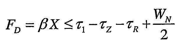
도 11 을 검토함으로써, 요구되는 수학식은 최대 광섬유 케이블 길이가 유도되는 것으로부터 결정될 수 있다. 전술한 바와 같이, 시스템 시간의 원격국의 센스는 광섬유 지연, 중계기 지연 및 중계기로부터 원격국으로의 전파지연의 합만큼 지연된다. 이것은 원격국이 그 이웃 파일럿을 찾으려고 시도할 때, PN1' 라고 표기된 지연값에서 그 이웃 세트 검색 윈도우, SRCH_WIN_N 에 집중하는 것을 의미한다. 따라서, 원격국 검색 함수가 섹터로부터의 PN1 에너지 방송을 발견하고자 한다면, 이웃 세트 검색 윈도우 사이즈의 절반을 감한 중계기 커버리지의 에지로의 중계기를 통한 전체 지연은 기지국 안테나로부터 섹터 커버리지의 에지까지의 지연 이하여야 한다. 수학적으로 이하와 같다.By reviewing FIG. 11, the required equation can be determined from which the maximum fiber optic cable length is derived. As mentioned above, the sense of the remote station in system time is delayed by the sum of the fiber delay, the repeater delay and the propagation delay from the repeater to the remote station. This means that when a remote station attempts to find its neighbor pilot, it concentrates on its neighbor set search window, SRCH_WIN_N, at a delay denoted PN1 '. Thus, if the remote station search function is to find PN1 energy broadcasts from a sector, the total delay through the repeater to the edge of repeater coverage subtracted half of the neighbor set search window size is less than the delay from the base station antenna to the edge of sector coverage. Should be It is mathematically as follows.

여기에서,From here,
![]()
![]()
이러한 관계식은, 이 때 이웃 세트 검색 윈도우 사이즈가 사용중이라는 것을 제외하면 제 1 경우에서 유도된 식과 유사한 형태이다. SRCH_WIN_A≤SRCH_WIN_N 이라는 조건 하에서, 상이한 PNs 간의 전환은 이러한 경우에서 제 1 경우보다 약간 더 긴 광섬유 케이블 길이를 허용할 수도 있다.This relation is similar to the one derived in the first case except that the neighbor set search window size is in use. Under the condition that SRCH_WIN_A ≦ SRCH_WIN_N, switching between different PNs may allow a slightly longer fiber optic cable length in this case than the first case.
완전성을 위해서, 전술한 관계식은 이하와 같이 간략화될 수 있다.For the sake of completeness, the above relation can be simplified as follows.

이러한 관계식은 물리적 광섬유 길이의 관점에서 이하와 같이 표현될 수 있다.This relationship can be expressed as follows in terms of physical fiber length.

전술한 관계식에 충실한 것은 원격국 검색기가 중계기 및 섹터가 상이한 PN 을 방송하는 경우에 있어서 ZR 로부터 Z1 으로 전환하면서 섹터로부터의 순방향 링크 신호를 찾을 수 있다는 것을 보장한다. 즉, 이들은 상이한 순방향 링크 신호를 방송하고 있다. 섹터 커버리지 영역으로부터 중계기 커버리지 영역으로 원격국이 전환하는 이벤트는 이전에 유도된 동일한 관계식을 산출할 것이다.Sticking to the above relation ensures that the remote station searcher can find the forward link signal from the sector while switching from ZR to Z1 in the case where the repeater and sector broadcast different PNs. That is, they are broadcasting different forward link signals. The event that the remote station switches from the sector coverage area to the repeater coverage area will yield the same relation previously derived.
Ⅵ. 기지국 액세스 Ⅵ. Base station access 윈도우window
이제까지, 원격국 내에 존재하는 검색 윈도우의 상대적인 타이밍 및 함수를 설명하였다. 보다 상세하게는 아이들 상태 및 트래픽 상태 모두에서, 중계기 커버리지 영역으로/영역으로부터 전환할 때 원격국의 검색 프로세스에 대한 지연 효과가 고려되었다.So far, the relative timing and function of the search window present in the remote station has been described. More specifically, in both idle and traffic conditions, the delay effect on the retrieval process of the remote station is considered when switching to / from the repeater coverage area.
그러나, 액세스와 관련하여 고려해야 할 하나의 다른 검색 윈도우가 존재한다. 이러한 윈도우는 기지국 내에 존재하며, 기지국이 원격국으로부터의 액세스 시도를 식별 및 상관하는 것을 시도하는 최대 시간 지연을 설정한다. 즉, 이러한 검색 윈도우는 기지국이 진입하는 액세스 시도를 검색하는 최대 양방향 지연을 설정한다. 도 4 는 이러한 지연을 도시한다.However, there is one other search window to consider with respect to access. This window resides in the base station and sets the maximum time delay at which the base station attempts to identify and correlate access attempts from remote stations. In other words, this search window sets the maximum bi-directional delay at which the base station searches for incoming access attempts. 4 illustrates this delay.
기지국 액세스 윈도우 파라미터 설정에서 광섬유 중계기의 사용으로부터 임의의 추가된 지연을 설명하는 것이 필요하다. 즉, 광섬유 지연의 추가는 추가된 양방향 지연을 설명하기 위해 기지국 액세스 윈도우를 확장하는 것을 필요로 할 수도 있다. 이러한 추가 없이, 기지국은 중계기 커버리지 영역에서의 원격국으로부터 시작하는 액세스 조사를 프로세싱하지 않아서 중계기 커버리지 영역 내로부터 네트워크에 액세스하는 원격국의 불능을 발생시킬 수도 있다. It is necessary to account for any added delay from the use of fiber optic repeaters in base station access window parameter settings. That is, the addition of the fiber delay may require extending the base station access window to account for the added bidirectional delay. Without this addition, the base station may not process access probes starting from remote stations in the repeater coverage area, resulting in the inability of remote stations to access the network from within the repeater coverage area.
이러한 검색 윈도우의 정확한 범위는 표준화되지 않는다. 이들은 CDMA 네트워크 설비의 각 벤더의 영역이다. 따라서, 윈도우는 CDMA 네트워크 설비의 특정 벤더에 의존한다.The exact range of this search window is not standardized. These are the areas of each vendor of the CDMA network facility. Thus, the window depends on the specific vendor of the CDMA network facility.
Ⅶ. 요약Iii. summary
기지국 섹터에 접속하는 광섬유 중계기에 대한 최대 광섬유 케이블 지연을 결정하기 위해 2 개의 식이 전개되었다. 중요한 2 개의 경우가 있다. 제 1 경우는 원격국이 전환중에 있는 기지국 섹터로서 중계기가 동일한 PN 오프셋 (동일한 순방향 링크) 을 운반하는 경우이다. 이러한 경우에, 최대 광섬유 지연은 (식 6) 과 같다. 제 2 경우는 원격국이 섹터로부터 전환하거나 섹터로 전환하는 섹터와 상이한 섹터로부터 중계기가 순방향 링크를 중계방송하고 있는 상황에 관한 것이다. 이 경우에, 최대 광섬유 케이블 길이는 (식 10) 과 같다.Two equations were developed to determine the maximum fiber optic cable delay for the fiber repeater connecting to the base station sector. There are two important cases. The first case is where the repeater carries the same PN offset (same forward link) as the base station sector that the remote station is switching over. In this case, the maximum optical fiber delay is equal to (Equation 6). The second case relates to a situation in which the repeater relays the forward link from a sector different from the sector which the remote station switches from or to the sector. In this case, the maximum optical fiber cable length is equal to (Equation 10).
![]()
![]()

여기에서,From here,
![]()
![]()
![]()
![]()
![]()
![]()
![]()
![]()
또한,중계기와 기지국 사이의 최대 전파지연 PD 는, 원격국이 섹터로부터 전환하거나 섹터로 전환하는 그 섹터와 상이한 섹터로부터 중계기라 순방향 링크를 재방송하는 경우에, 이하와 같다.Further, the maximum propagation delay PD between the repeater and the base station is as follows when the remote station rebroadcasts the forward link from a sector different from the sector to which the remote station switches from or to the sector.

여기에서,From here,
![]()
![]()
Ⅷ. 애플리케이션Iii. Application
도 12 는 통신 시스템에 대한 예시적인 장치 (1200) 를 도시하는데, 여기에서 이동국은 광섬유 케이블을 이용하여 기지국에 부착된 중계기를 통해 기지국과 통신한다. 장치 (1200) 는 허용가능하고/하거나 충분한 광섬유 케이블의 물리적 길이를 결정하는데 이용될 수도 있다. 장치 (1200) 는 가산 유닛 (1210) 및 제산 유닛 (1220) 을 구비할 수도 있다.12 shows an
가산 유닛 (1210) 은 제 2 전파지연값 ![]()
![]()
![]()
![]()
![]()
![]()
![]()
![]()
![]()
![]()
![]()
![]()
제산 유닛 (1220) 은 가산값 s3 를 광섬유 케이블 길이에 대한 광섬유 케이블 지연값의 비율값인 ![]()
![]()
도 13 은 통신 시스템에 대한 예시적인 장치 (1300) 를 도시하는데, 여기에서 이동국은 광섬유 케이블을 이용하여 기지국에 부착된 중계기를 통해 기지국과 통신한다. 장치 (1300) 는 광섬유 케이블의 소망하는 물리적 길이에 대하여 동작가능한 검색 윈도우 사이즈를 결정하는데 이용될 수도 있다. 장치 (1300) 는 승산 유닛 (1310), 가산 유닛 (1320) 및 제 2 승산 유닛 (1330) 을 구비할 수도 있다.13 shows an
승산 유닛 (1310) 은 소망하는 광섬유 케이블의 길이 x 를 광섬유 케이블 길이에 대한 광섬유 케이블 지연값의 비율값인 ![]()
![]()
가산 유닛 (1320) 은 제 1 전파지연값 ![]()
![]()
![]()
![]()
![]()
![]()
![]()
![]()
![]()
![]()
![]()
![]()
제 2 승산 유닛 (1320) 은 s3 를 2배로 하여 x 에 대한 원하는 검색 윈도우 사이즈를 획득하도록 구성된다. 그러나, 제 2 승산 유닛 (1320) 은 P, ![]()
![]()
![]()
![]()
![]()
![]()
도 14 는 통신 시스템에 사용되는 방법 (1400) 을 도시하는데, 여기에서 이동국은 광섬유 케이블을 이용하여 기지국에 부착된 중계기를 통해 기지국과 통신한다. 방법 (1400) 은 원하는 검색 윈도우 사이즈에 대한 광섬유 케이블의 허용가능한 길이를 결정하는데 이용될 수도 있다.14 illustrates a
방법 (1400) 은 원하는 검색 윈도우 사이즈 W 를 시간으로 결정하는 단계를 포함한다 (1410). 몇몇 실시형태에서, 방법 (1400) 은 검색 윈도우 사이즈의 범위를 결정하는 단계를 포함할 수도 있다. 몇몇 다른 실시형태에서, 방법 (1400) 은 복수의 검색 윈도우 사이즈를 결정하는 단계를 포함할 수도 있다. 그 후에, 최대 광섬유 케이블 지연값 FD 이 원하는 검색 윈도우 사이즈에 기초하여 결정된다 (1420).The
최대 광섬유 케이블 지연값은 기지국으로부터 이동국으로의 제 1 전파지연값 ![]()
![]()
![]()
![]()
![]()
![]()
보다 상세하게는, 광섬유 케이블의 최대 길이는 제 1 전파지연값에서 제 2 전파지연값 및 내부 지연값을 감산하여 제 1 가산값을 획득하고, 이러한 제 1 가산값과 소망하는 검색 윈도우 사이즈의 절반을 가산하여 제 2 가산값을 획득함으로써 결정될 수도 있다.More specifically, the maximum length of the optical fiber cable is obtained by subtracting the second propagation delay value and the internal delay value from the first propagation delay value to obtain a first addition value, which is half of the first addition value and the desired search window size. May be determined by adding and obtaining a second addition value.
도 14 를 다시 참조하면, 방법 (1400) 은 광섬유 케이블 길이에 대한 광섬유 케이블 지연값의 비율값 ![]()
![]()
도 15 는 통신 시스템에 사용되는 방법 (1500) 을 도시하는데, 여기에서 이 동국은 광섬유 케이블을 이용하여 기지국에 부착된 중계기를 통해 기지국과 통신한다. 방법 (1500) 은 광섬유 케이블의 소망하는 길이에 대한 검색 윈도우 사이즈를 결정하는데 이용될 수도 있다.15 illustrates a
방법 (1500) 은 광섬유 케이블의 소망하는 길이를 결정하는 단계 (1510), 광섬유 케이블 길이에 대한 광섬유 케이블 지연값의 비율값을 결정하는 단계 (1520), 기지국으로부터 이동국으로의 제 1 전파지연값을 결정하는 단계 (1530), 중계기로부터 이동국으로의 제 2 지연값을 결정하는 단계 (1540), 중계기의 내부 지연값을 결정하는 단계 (1550) 및 광섬유 케이블의 소망하는 길이, 비율값, 내부 지연값 및 제 1 및 제 2 전파 지연값에 기초하여 검색 윈도우 사이즈를 결정하는 단계 (1560) 를 포함할 수도 있다.The
검색 윈도우 사이즈는 비율값에 소망하는 광섬유 케이블의 길이를 승산하고, 제 2 전파지연값 및 내부 지연값과 광섬유 케이블 지연값을 가산하여 제 1 가산값을 획득하고, 제 1 가산값에서 제 1 전파지연값을 감산하여 제 2 가산값을 획득하고 검색 윈도우 사이즈를 결정하기 위하여 제 2 가산값을 2배로하여 결정될 수도 있다.The search window size multiplies the ratio value by the desired length of the optical fiber cable, adds the second propagation delay value and the internal delay value and the optical fiber cable delay value to obtain the first addition value, and the first propagation value from the first addition value. It may be determined by doubling the second addition in order to subtract the delay to obtain a second addition and determine the search window size.
장치 (1200) 는 방법 (1400) 을 달성하는데 이용될 수도 있으며 장치 (1300) 는 방법 (1500) 을 달성하는데 이용될 수도 있다.The
또한, 도 16 은 통신 시스템에 대한 예시적인 장치 (1600) 를 도시하는데, 여기에서 이동국은 광섬유 케이블을 이용하여 기지국에 부착된 중계기를 통해 기지국과 통신한다. 장치 (1600) 는 광섬유 케이블의 길이가 소망하는 검색 윈도우 사이즈에 충분한지 여부를 결정하는데 이용될 수도 있다.FIG. 16 also shows an
장치 (1600) 는 저장매체 (1620) 및 프로세서 (1620) 를 구비할 수도 있다. 저장 매체 (1610) 는 기지국으로부터 이동국으로의 제 1 전파 지연값, 중계기로부터 이동국으로의 제 2 전파지연값, 중계기의 내부 지연값 및 소망하는 검색 윈도우 사이즈를 저장하도록 구성된다. 프로세서 (1620) 는 저장 매체 (1610) 에 결합되고, 제 1 및 제 2 전파지연값, 내부 지연값 및 소망하는 검색 윈도우 사이즈에 기초하여 광섬유 케이블의 길이가 소망하는 검색 윈도우 사이즈에 충분한지 여부를 결정하도록 구성된다. 여기에서, 프로세서 판독가능한 코드는 저장 매체 (1610) 에 저장될 수도 있으며 광섬유 케이블의 길이가 소망하는 검색 윈도우 사이즈에 충분한지 여부를 결정하기 위해 프로세서 (1620) 에 의해 실행된다. 몇몇 실시형태에서, 장치 (1600) 는 광섬유 케이블의 길이가 소망하는 검색 윈도우 사이즈에 충분한지 여부를 결정하기 위해 장치 (1200) 와 같은 장치 (미도시) 를 구현할 수도 있다.The
장치 (1600) 는 프로세서 (1620) 에 결합되어 광섬유 케입ㄹ의 물리적 길이를 결정하도록 구성되는 측정 유닛 (1630) 을 추가로 구비할 수도 있다. 즉, 측정 유닛 (1630) 은 중계기를 기지국에 부착시키기 위해 설치된 광섬유 케이블의 실제 길이를 측정 및 획득한다. 여기에서, 측정 유닛 (1630) 은 광섬유 케이블이 설치된 이후에 광섬유 케이블의 길이를 측정할 수도 있다. 광섬유 케이블의 길이는 공지의 이용가능한 기술중 임의의 하나에 의해 측정될 수도 있다.The
또한, 장치 (1600) 는 프로세서 (1620) 에 결합되고 광섬유 케이블의 길이가 소망하는 윈도우 사이즈에 충분하지 않는지를 나타내는 신호를 사용자에게 출력하도록 구성되는 출력 유닛 (1640) 을 추가로 구비할 수도 있다. 예시적인 출력 유닛 (1640) 은 이에 한정되지는 않지만 디스플레이, 오디오 장치 또는 LED 일 수도 있다.The
따라서, 장치 (1600) 는 기지국에 중계기를 부착시키기 위하여 광섬유 케이블을 설치하는 필드 기술자에 의해 이용될 수도 있다.Thus, the
도 17 은 통신 시스템에 사용되는 방법 (1700) 을 도시하는데, 여기에서 이동국은 광섬유 케이블을 이용하여 기지국에 부착된 중계기를 통하여 기지국과 통신한다. 방법 (1700) 은 광섬유 케이블의 길이가 소망하는 검색 윈도우 사이즈에 충분한지 여부를 결정하는데 이용될 수도 있다.17 illustrates a
방법 (1700) 은 소망하는 검색 윈도우 시간 사이즈를 결정하는 단계 (1710), 소망하는 검색 윈도우 사이즈에 기초하여 허용가능한 광섬유 케이블 지연값을 결정하는 단계 (1720), 광섬유 케이블 길이에 대한 광섬유 케이블 지연값의 비율값을 결정하는 단계 (1730), 광섬유 케이블의 길이를 결정하는 단계 (1740) 및 허용가능한 광섬유 케이블 지연값 및 비율값에 기초하여 광섬유 케이블의 길이가 소망하는 검색 윈도우 사이즈에 충분한지 여부를 결정하는 단계 (1750) 를 포함할 수도 있다.The
여기에서, 광섬유 케이블의 길이는 기지국에 중계기를 부착시키기 위해 광섬유 케이블을 설치할 때 결정될 수도 있다. 유사하게, 광섬유 케이블의 길이가 충분한지 여부를 결정하는 것은 기지국에 중계기를 부착시키기 위해 광섬유 케이블 을 설치할 때 결정될 수도 있다.Here, the length of the optical fiber cable may be determined when installing the optical fiber cable to attach the repeater to the base station. Similarly, determining whether the length of the fiber optic cable is sufficient may be determined when installing the fiber optic cable to attach a repeater to the base station.
또한, 허용가능한 광섬유 케이블 지연값은 소망하는 검색 윈도우 사이즈에 대한 최대 광섬유 케이블 지연을 결정함으로써 결정될 수도 있다. 그 후, 최대 광섬유 케이블 지연값은 기지국에서 이동국으로의 제 1 전파지연값을 결정하고, 중계기로부터 이동국으로의 제 2 전파지연값을 결정하고, 중계기의 내부 지연값을 결정함으로써 결정될 수도 있다. 최대 광섬유 케이블 지연값은 소망하는 검색 윈도우 사이즈, 내부 지연값 및 제 1 및 제 2 전파지연값에 기초하여 결정될 수도 있다.The allowable fiber optic cable delay value may also be determined by determining the maximum fiber optic cable delay for the desired search window size. The maximum fiber optic cable delay value may then be determined by determining a first propagation delay value from the base station to the mobile station, determining a second propagation delay value from the repeater to the mobile station, and determining an internal delay value of the repeater. The maximum fiber optic cable delay value may be determined based on the desired search window size, the internal delay value, and the first and second propagation delay values.
보다 상세하게는, 광섬유 케이블의 길이가 충분한지 여부의 결정은 제 1 전파지연값에서 제 2 전파지연값 및 내부 지연값을 감산하여 제 1 가산값을 획득하고, 제 1 가산값에 소망하는 검색 윈도우 사이즈의 절반을 가산하여 제 2 가산값을 획득하고, 제 2 가산값을 비율값으로 제산하여 이루어진다.More specifically, the determination of whether the length of the optical fiber cable is sufficient is obtained by subtracting the second propagation delay value and the internal delay value from the first propagation delay value to obtain the first addition value, and the desired search to the first addition value. The second addition value is obtained by adding half of the window size, and the second addition value is divided by the ratio value.
Ⅸ. 결론Iii. conclusion
전술한 바와 같이, 중계기가 광섬유 링크를 이용하여 기지국에 부착되는 통신 시스템에 이용하기 위해 허용될 수 있는 광섬유 케이블 지연의 양과 검색 윈도우 사이즈 사이의 관계가 제시되었다. 광섬유 케이블의 허용가능한 양 및/또는 광섬유 케이블의 길이는 광섬유 케이블 지연의 최대량 및/또는 광섬유 케이블의 최대길이 이하의 임의의 값이다. 또한, ![]()
![]()
![]()
![]()
![]()
![]()
![]()
![]()
또한, 실시형태가 광섬유 링크를 이용하여 설명되었다고 할지라도, 당업자에게 이러한 실시형태가 이에 한정되지는 않지만 유선 및 동축 케이블과 같은 다른 물리적 링크에 적용될 수도 있음은 자명하다. 이러한 실시형태는 전술한 바와 같이 ![]()
![]()
또한, 실시형태는 하드웨어, 소프트웨어, 펌웨어 (firmware), 미들웨어 (middleware), 마이크로코드 (microcode) 또는 임의의 그 조합으로써 구현될 수도 있다. 소프트웨어, 펌웨어, 미들웨어 또는 마이크로코드로 구현되는 경우, 필요한 작업을 수행하기 위한 프로그램 코드 또는 코드 세그먼트 (segment) 는 저장매체 (1610) 또는 별개의 저장매체 (미도시) 와 같은 기계 판독가능한 매체에 저장될 수도 있다. 프로세서가 필요한 작업을 수행할 수도 있다. 코드 세그먼트는 절차, 함수, 서브프로그램, 프로그램, 루틴 (routine), 서브루틴, 모듈, 소프트웨어 패키지, 클래스, 명령어의 임의의 조합, 데이터 구조, 또는 프로그램 문장을 나타낼 수도 있다. 코드 세그먼트는 정보, 데이터, 독립변수 (argument), 파라미터, 또는 메모리 컨텐츠를 전달 및/또는 수신함으로써 다른 코드 세그먼트 또는 하드웨어 회로에 결합될 수도 있다. 정보, 독립변수, 파라미터, 데이터 등은 메모리 공유, 메시지 전달, 토큰 (token) 전달, 네트워크 송신 등을 포함하는 임의의 적절한 수단을 통해 전달, 포워딩 (forwarding) 또는 송신될 수도 있다.Embodiments may also be implemented as hardware, software, firmware, middleware, microcode, or any combination thereof. If implemented in software, firmware, middleware or microcode, the program code or code segments for performing the necessary work may be stored on a machine-readable medium, such as
전술한 실시형태는 단지 예시적이며 본 발명을 제한하는 것으로 해석되어서는 않된다. 본 실시형태의 설명은 예시적인 것이며, 청구범위를 제한하는 것이 아니다. 이와 같이, 본 교시는 다른 타입의 장치에 용이하게 적용될 수 있으며, 다수의 변형, 수정 및 변화가 당해 기술의 당업자에게 자명할 것이다.The foregoing embodiments are merely exemplary and should not be construed as limiting the invention. The description of this embodiment is illustrative and does not limit the scope of the claims. As such, the present teachings can be readily applied to other types of devices, and many variations, modifications, and variations will be apparent to those skilled in the art.
Claims (45)
Applications Claiming Priority (2)
| Application Number | Priority Date | Filing Date | Title |
|---|---|---|---|
| US46997503P | 2003-05-12 | 2003-05-12 | |
| US60/469,975 | 2003-05-12 |
Publications (1)
| Publication Number | Publication Date |
|---|---|
| KR20060003095A true KR20060003095A (en) | 2006-01-09 |
Family
ID=33452344
Family Applications (1)
| Application Number | Title | Priority Date | Filing Date |
|---|---|---|---|
| KR1020057021583A KR20060003095A (en) | 2003-05-12 | 2004-05-12 | Method and apparatus for use in a communication system |
Country Status (10)
| Country | Link |
|---|---|
| US (1) | US7593360B2 (en) |
| EP (1) | EP1623525B1 (en) |
| JP (1) | JP4564013B2 (en) |
| KR (1) | KR20060003095A (en) |
| CN (1) | CN100569027C (en) |
| AT (1) | ATE460822T1 (en) |
| CA (1) | CA2525572A1 (en) |
| DE (1) | DE602004025918D1 (en) |
| RU (1) | RU2369020C2 (en) |
| WO (1) | WO2004102859A2 (en) |
Cited By (1)
| Publication number | Priority date | Publication date | Assignee | Title |
|---|---|---|---|---|
| KR20160095339A (en) | 2015-02-03 | 2016-08-11 | 한국기계연구원 | Spray coating unit, and a coating system using the same |
Families Citing this family (28)
| Publication number | Priority date | Publication date | Assignee | Title |
|---|---|---|---|---|
| US8144671B2 (en) | 2005-07-01 | 2012-03-27 | Twitchell Jr Robert W | Communicating via nondeterministic and deterministic network routing |
| US7142107B2 (en) | 2004-05-27 | 2006-11-28 | Lawrence Kates | Wireless sensor unit |
| KR20060005219A (en) * | 2004-07-12 | 2006-01-17 | 삼성전자주식회사 | Apparatus and method for synchronizing of optic repeater in a communication system using time division orthogonal frequency division multiplexing scheme |
| US7558242B1 (en) * | 2005-03-28 | 2009-07-07 | Hazenson Michael Boris | Method of building flexible and effective transmission systems for two-way communications |
| JP4772038B2 (en) * | 2005-03-30 | 2011-09-14 | パナソニック株式会社 | Wireless communication apparatus and wireless communication method |
| US7949032B1 (en) * | 2005-05-16 | 2011-05-24 | Frost Edward G | Methods and apparatus for masking and securing communications transmissions |
| US20080205323A1 (en) * | 2007-02-22 | 2008-08-28 | Samsung Electronics Co., Ltd. | Apparatus and method for resource allocation considering buffering in relay wireless communication system |
| US8059614B2 (en) * | 2007-08-31 | 2011-11-15 | Samsung Electronics Co., Ltd. | Pseudorandom noise selection method for mobile communication sites |
| FI20075697A0 (en) * | 2007-10-02 | 2007-10-02 | Nokia Siemens Networks Oy | Method, computer program, apparatus and system |
| US8325616B2 (en) * | 2008-01-17 | 2012-12-04 | Broadcom Corporation | Method and system for determination and exchange of network timing information |
| US8467365B1 (en) | 2008-01-24 | 2013-06-18 | Sprint Spectrum L.P. | Method and system for defining search windows based on mobile station location |
| US8055273B1 (en) * | 2008-02-07 | 2011-11-08 | Sprint Spectrum L.P. | Method and system for defining a search window based on a mobile station's direction of motion and speed |
| CN101960876A (en) * | 2008-02-27 | 2011-01-26 | 松下电器产业株式会社 | Relay station in mobile communication system, mobile station, and relay transmission method |
| WO2009140669A2 (en) | 2008-05-16 | 2009-11-19 | Terahop Networks, Inc. | Securing, monitoring and tracking shipping containers |
| JP5031687B2 (en) * | 2008-07-03 | 2012-09-19 | 株式会社エヌ・ティ・ティ・ドコモ | Radio base station apparatus, radio communication system, and delay correction method |
| US8977266B2 (en) * | 2009-04-27 | 2015-03-10 | Ntt Docomo, Inc. | Mobile communication system |
| KR101893460B1 (en) | 2009-09-28 | 2018-08-31 | 삼성전자주식회사 | Extending physical downlink control channels |
| US8270969B1 (en) * | 2010-03-24 | 2012-09-18 | Sprint Spectrum L.P. | Systems and methods for adjusting an access search window based on movement |
| GB201008710D0 (en) * | 2010-05-25 | 2010-07-07 | Jaguar Cars | Vehicle communications |
| CN102204313B (en) * | 2011-05-19 | 2013-12-04 | 华为技术有限公司 | Resource multiplex method and device & swithcing method and device thereof |
| GB2482761B (en) * | 2011-06-17 | 2015-12-23 | Airwave Solutions Ltd | Communications system, apparatus and method |
| EP2557870B1 (en) | 2011-08-10 | 2020-07-08 | Alcatel Lucent | Configuring transmissions |
| US8879605B1 (en) | 2012-04-02 | 2014-11-04 | Sprint Spectrum L.P. | Mobile station time reference that is adjusted based on propagation delay |
| US9002359B1 (en) | 2012-04-12 | 2015-04-07 | Sprint Spectrum L.P. | Method and system for intelligent determination of pseudonoise (PN) offsets |
| US9832080B2 (en) * | 2012-05-03 | 2017-11-28 | Philips Lighting Holding B.V. | Method and device for commissioning of nodes of a network |
| CN103532629B (en) * | 2012-07-05 | 2016-03-30 | 京信通信技术(广州)有限公司 | A kind of method and device improving the adjustment of digital optical fiber direct station uplink time delay |
| CN106330325B (en) * | 2016-08-24 | 2018-10-12 | 钱秀英 | Face formula covers comprehensive wireless fibre optic repeater |
| US11677462B1 (en) * | 2020-05-18 | 2023-06-13 | VeEX, Inc. | Landmark correlation mechanism |
Family Cites Families (17)
| Publication number | Priority date | Publication date | Assignee | Title |
|---|---|---|---|---|
| US5381444A (en) | 1991-10-31 | 1995-01-10 | Fujitsu Limited | Radio environment measuring system |
| US5289390A (en) * | 1992-05-22 | 1994-02-22 | Hewlett-Packard Company | Method for determining the electrical cable length of an active ring of a token ring local area network |
| DE69527222T2 (en) * | 1994-03-24 | 2003-03-13 | Hitachi Int Electric Inc | Relay station for a paging system |
| US5838580A (en) * | 1996-06-20 | 1998-11-17 | Sun Microsystems, Inc. | Method of optimizing repeater placement in long lines of a complex integrated circuit |
| US6507741B1 (en) | 1997-12-17 | 2003-01-14 | Nortel Networks Limited | RF Repeater with delay to improve hard handoff performance |
| US6094562A (en) * | 1998-04-07 | 2000-07-25 | Lucent Technologies Inc. | Timing compensation for distant base station antennas in telecommunication systems |
| US6366571B1 (en) * | 1998-06-01 | 2002-04-02 | Ameritech Corporation | Integration of remote microcell with CDMA infrastructure |
| JP3322240B2 (en) * | 1999-05-10 | 2002-09-09 | 日本電気株式会社 | CDMA receiver |
| GB2360894B (en) * | 2000-03-30 | 2004-11-10 | Peter Thomas Bosson | Display device support system |
| US6385435B1 (en) * | 2000-04-20 | 2002-05-07 | Jhong Sam Lee | Coupled interference concellation system for wideband repeaters in a cellular system |
| US7194020B1 (en) * | 2000-06-09 | 2007-03-20 | Lucent Technologies Inc. | Method and apparatus for dynamically adjusting acquisition search window |
| US7039418B2 (en) * | 2000-11-16 | 2006-05-02 | Qualcomm Incorporated | Position determination in a wireless communication system with detection and compensation for repeaters |
| US7006461B2 (en) * | 2001-09-17 | 2006-02-28 | Science Applications International Corporation | Method and system for a channel selective repeater with capacity enhancement in a spread-spectrum wireless network |
| JP2003139841A (en) * | 2001-10-31 | 2003-05-14 | Hitachi Ltd | Portable terminal device with built-in gps |
| US7280517B2 (en) * | 2001-11-02 | 2007-10-09 | At&T Corp. | Wireless LANs and neighborhood capture |
| CN1192650C (en) * | 2002-04-26 | 2005-03-09 | 华为技术有限公司 | Directly amplifying station and its mobile station locating method |
| CN1266976C (en) * | 2002-10-15 | 2006-07-26 | 华为技术有限公司 | Mobile station positioning method and its direct broadcasting station |
-
2004
- 2004-05-12 CN CNB2004800200106A patent/CN100569027C/en not_active Expired - Fee Related
- 2004-05-12 AT AT04752206T patent/ATE460822T1/en not_active IP Right Cessation
- 2004-05-12 US US10/844,666 patent/US7593360B2/en not_active Expired - Fee Related
- 2004-05-12 RU RU2005138495/09A patent/RU2369020C2/en not_active IP Right Cessation
- 2004-05-12 DE DE602004025918T patent/DE602004025918D1/en not_active Expired - Lifetime
- 2004-05-12 EP EP04752206A patent/EP1623525B1/en not_active Expired - Lifetime
- 2004-05-12 KR KR1020057021583A patent/KR20060003095A/en not_active Application Discontinuation
- 2004-05-12 WO PCT/US2004/015130 patent/WO2004102859A2/en active Application Filing
- 2004-05-12 CA CA002525572A patent/CA2525572A1/en not_active Abandoned
- 2004-05-12 JP JP2006533064A patent/JP4564013B2/en not_active Expired - Fee Related
Cited By (1)
| Publication number | Priority date | Publication date | Assignee | Title |
|---|---|---|---|---|
| KR20160095339A (en) | 2015-02-03 | 2016-08-11 | 한국기계연구원 | Spray coating unit, and a coating system using the same |
Also Published As
| Publication number | Publication date |
|---|---|
| RU2005138495A (en) | 2006-06-27 |
| US7593360B2 (en) | 2009-09-22 |
| CN1849833A (en) | 2006-10-18 |
| EP1623525B1 (en) | 2010-03-10 |
| ATE460822T1 (en) | 2010-03-15 |
| CN100569027C (en) | 2009-12-09 |
| WO2004102859A3 (en) | 2006-05-26 |
| US20040233874A1 (en) | 2004-11-25 |
| JP4564013B2 (en) | 2010-10-20 |
| EP1623525A2 (en) | 2006-02-08 |
| CA2525572A1 (en) | 2004-11-25 |
| DE602004025918D1 (en) | 2010-04-22 |
| WO2004102859A2 (en) | 2004-11-25 |
| RU2369020C2 (en) | 2009-09-27 |
| EP1623525A4 (en) | 2008-07-02 |
| JP2007500488A (en) | 2007-01-11 |
Similar Documents
| Publication | Publication Date | Title |
|---|---|---|
| KR20060003095A (en) | Method and apparatus for use in a communication system | |
| RU2462836C2 (en) | Method to confirm location of subscriber in service systems in closed structures | |
| RU2216102C2 (en) | Method and system for locating mobile cellular terminal | |
| RU2315434C2 (en) | Method for identification and monitoring of repeater traffic in code division multi-access system and system for its realization | |
| JP2915851B2 (en) | Time synchronous communication system | |
| JP3192428B2 (en) | Method and mobile station for performing handover in a CDMA cellular radio system | |
| AU751791B2 (en) | Extended range concentric cell base station | |
| MXPA02001965A (en) | Method and system for initiating idle handoff in a wireless communications system. | |
| US6205132B1 (en) | Method for accessing a cell using two pilot channels in a CDMA communication system of an asynchronous or quasi-synchronous mode | |
| AU4475799A (en) | A method for extending the range of a wireless communication system | |
| US20040258100A1 (en) | Location service support for distributed bts architecture | |
| KR100683906B1 (en) | Method and System for Providing Location Finding Service by Using Frequency Offset | |
| EP1283651A1 (en) | A method and apparatus for handover in a CDMA cellular communication system | |
| JP3080204B2 (en) | Channel switching method during communication of spread spectrum mobile communication | |
| KR100562477B1 (en) | Repeater including PN shadow radio finger equipment being used in mobile communication network | |
| KR100570180B1 (en) | Method and apparatus to prevent spill-over signals that break into radio frequency repeater , using multi-path searcher | |
| KR101001020B1 (en) | Repeater apparatus for supporting a plurality of networks | |
| GB2362297A (en) | Location based consideration for cellular telephone handoff | |
| Kim et al. | Repeater Effect Suppression Method for TDOA algorithm in CDMA system | |
| KR20040015785A (en) | Apparatus and method to effectively integrate repeater system and wireless common channel transmitter to produce unique identity signal in the down link of the repeater system in order to reduce the position estimation error of mobile station due to the repeater system in advanced forward link trilateration utilizing base station pilot signals in code division multiple access mobile communication systems | |
| KR20030014894A (en) | A Transceiver For Mobile Communication Repeater Using Tx/Rx Diversity Method | |
| KR20050060289A (en) | Repeater for mobile telecommunication | |
| KR20030022907A (en) | Method for forming distribute antenna in simulcast transmission system | |
| KR20070018257A (en) | Mobile Communication System Having Virtual Cell | |
| KR20050065791A (en) | Receiver for base station |
Legal Events
| Date | Code | Title | Description |
|---|---|---|---|
| A201 | Request for examination | ||
| E902 | Notification of reason for refusal | ||
| E601 | Decision to refuse application |