KR200460912Y1 - Apparatus for Reducig Waiting time of Boiler - Google Patents
Apparatus for Reducig Waiting time of Boiler Download PDFInfo
- Publication number
- KR200460912Y1 KR200460912Y1 KR2020090016552U KR20090016552U KR200460912Y1 KR 200460912 Y1 KR200460912 Y1 KR 200460912Y1 KR 2020090016552 U KR2020090016552 U KR 2020090016552U KR 20090016552 U KR20090016552 U KR 20090016552U KR 200460912 Y1 KR200460912 Y1 KR 200460912Y1
- Authority
- KR
- South Korea
- Prior art keywords
- standby
- power
- boiler
- unit
- data
- Prior art date
Links
Images


Classifications
-
- F—MECHANICAL ENGINEERING; LIGHTING; HEATING; WEAPONS; BLASTING
- F24—HEATING; RANGES; VENTILATING
- F24H—FLUID HEATERS, e.g. WATER OR AIR HEATERS, HAVING HEAT-GENERATING MEANS, e.g. HEAT PUMPS, IN GENERAL
- F24H9/00—Details
- F24H9/20—Arrangement or mounting of control or safety devices
- F24H9/2007—Arrangement or mounting of control or safety devices for water heaters
- F24H9/2035—Arrangement or mounting of control or safety devices for water heaters using fluid fuel
-
- F—MECHANICAL ENGINEERING; LIGHTING; HEATING; WEAPONS; BLASTING
- F24—HEATING; RANGES; VENTILATING
- F24H—FLUID HEATERS, e.g. WATER OR AIR HEATERS, HAVING HEAT-GENERATING MEANS, e.g. HEAT PUMPS, IN GENERAL
- F24H1/00—Water heaters, e.g. boilers, continuous-flow heaters or water-storage heaters
- F24H1/10—Continuous-flow heaters, i.e. heaters in which heat is generated only while the water is flowing, e.g. with direct contact of the water with the heating medium
- F24H1/107—Continuous-flow heaters, i.e. heaters in which heat is generated only while the water is flowing, e.g. with direct contact of the water with the heating medium using fluid fuel
-
- F—MECHANICAL ENGINEERING; LIGHTING; HEATING; WEAPONS; BLASTING
- F24—HEATING; RANGES; VENTILATING
- F24H—FLUID HEATERS, e.g. WATER OR AIR HEATERS, HAVING HEAT-GENERATING MEANS, e.g. HEAT PUMPS, IN GENERAL
- F24H9/00—Details
- F24H9/20—Arrangement or mounting of control or safety devices
- F24H9/2064—Arrangement or mounting of control or safety devices for air heaters
- F24H9/2071—Arrangement or mounting of control or safety devices for air heaters using electrical energy supply
Landscapes
- Engineering & Computer Science (AREA)
- Physics & Mathematics (AREA)
- Thermal Sciences (AREA)
- Chemical & Material Sciences (AREA)
- Combustion & Propulsion (AREA)
- Mechanical Engineering (AREA)
- General Engineering & Computer Science (AREA)
- Heat-Pump Type And Storage Water Heaters (AREA)
- Supply And Distribution Of Alternating Current (AREA)
Abstract
본 고안은 가정용 순간식 가스 보일러의 대기 전력 저감 장치에 관한 것으로 특히, 가정용 순간식 가스 보일러에 있어서, 난방 또는 온수를 사용하지 않는 미연소 대기시간 동안 발생하는 제어 장치의 대기시 소비 전력을 저감하는 장치에 관한 것이다.
본 고안은 미연소 대기 시간 동안의 전력소모를 줄이기 위해 스위칭 파워 회로를 구성하고, 제어 장치 부속품의 전기 공급경로를 박동 부속품과 대기시 전기 차단 부속품으로 회로를 구분하여 가공상태에 따른 효율적인 통제를 행하는 방법으로 기존의 방식에 비해 대기시 소모 전력을 1/3로 저감되며 (보통 3W에서 1W로), 이를 통해 실제 연소 가동시간이 짧고 긴 대기시간을 가진 보일러의 경우 전력 요금 절감, 저발열, 소형화 친 환경성을 증진 시킬 수 있는 보일러의 대기 시간 전력 저감 장치를 제공하는데 그 목적이 있다.
상기 목적를 달성하기 위해 본 고안은 대기시 전력 저감 장치로서, 전원 공급부인 SMPS(Switching Mode Power Supply)(10);
보일러의 대기 전력 시에도 항상 동작하는 상시 입력부(20);
보일러의 대기 조건을 판단하고, 내부 전원 공급을 관리하며, 팬 및 펌프 정지 조건 또는 온수 전용, 타이머 예약 정지, 동파예방 운전 조건의 상태를 판단하여 정상 대기 모드의 전환을 통하여 대기모드에서 불필요한 회로의 전원 공급을 차단하는 대기 조건 판단 통제부(60);
상기 대기 조건 판단 통제부(60)의 제어에 의해 대기시 전력이 공급 및 차단되는 대기시 차단 입력부(30);
보일러의 전력 저감 장치의 각 부를 제어하는 연산 처리 제어부(50);
100ms주기로 충전 및 통신을 행하며, 통신 신호 처리부(40)와 매회 데이터의 송수신시 표준 데이터와 확장 데이터를 송수신하며, 셋업 모드 상태가 될 때 상기 확장 데이터에 셋업 데이터를 포함하여 송수신하며, 대기시에는 2초에 1회 주기로 기본 데이터만 교신하는 실내온도 조절기(70);
상기 연산 처리 제어부(50)의 명령에 의해 전원을 공급 받는 출력부(80); 및
송풍기 팬과 관련된 입, 출력 회로의 전원을 차단하여 대기 전력을 감소시키는 대기시 입출력 회로 출력 차단부(90)를 포함하고;
상기 통신 신호 처리부(40)는 정상 운전시에는 0.1초 주기로 기본 데이터 및 확장 데이터를 연산 처리부(50) 및 실내온도 조절기(70)와 연속 송/수신하고, 대기시에는 2초에 1회 주기로 기본 데이터만 교신하는 것을 특징으로 하는 보일러 대기 전력 저감 장치를 포함하는 것을 특징으로 한다.
보일러, 대기 시간, 저감, SMPS, 연산 처리 제어부
The present invention relates to an apparatus for reducing standby power of an instantaneous gas boiler for home use, in particular, in an instantaneous gas boiler for home use, to reduce standby power consumption of a control device generated during unburned standby time without heating or hot water. Relates to a device.
The present invention constructs a switching power circuit to reduce power consumption during unburned standby time, and divides the circuit of the power supply of the control device accessory into a pulsating accessory and an electric interruption accessory in standby to perform efficient control according to processing conditions. By using this method, the standby power consumption is reduced by 1/3 compared to the conventional method (usually from 3W to 1W), which reduces the power bill, generates heat, and reduces the power consumption for boilers with short actual combustion time and long standby time. It is an object of the present invention to provide a device for reducing the standby power of a boiler that can improve environmental friendliness.
The present invention to achieve the above object is a standby power reduction device, SMPS (Switching Mode Power Supply) 10 as a power supply;
Always input unit 20 that always operates even when the standby power of the boiler;
Determining the standby condition of the boiler, managing the internal power supply, and determining the status of fan and pump stop conditions or hot water only, timer reservation stop, freeze prevention operation condition, and switching to normal standby mode, A standby condition determination controller 60 to cut off the power supply;
A standby cutoff input unit 30 to which the standby power is supplied and cut off by the control of the standby condition determination controller 60;
Arithmetic processing control unit 50 for controlling each unit of the power reduction device of the boiler;
Charges and communicates at 100 ms periods, and transmits and receives standard data and extended data when the data is transmitted and received with the communication signal processing unit 40 each time, and transmits and receives the extended data including the setup data when in the setup mode. An indoor temperature controller 70 communicating only basic data once every two seconds;
An output unit 80 supplied with power by a command of the arithmetic processing control unit 50; And
A standby input / output circuit output blocker 90 for shutting off power of input and output circuits related to the blower fan to reduce standby power;
The communication signal processing unit 40 continuously transmits / receives basic data and extended data with the operation processing unit 50 and the room temperature controller 70 at 0.1 second intervals during normal operation, and basics once every 2 seconds when waiting. And a boiler standby power reduction device characterized by communicating only data.
Boiler, Wait Time, Reduction, SMPS
Description
본 고안은 가정용 순간식 가스 보일러의 대기 전력 저감 장치에 관한 것으로 특히, 가정용 순간식 가스 보일러에 있어서, 난방 또는 온수를 사용하지 않는 미연소 대기시간 동안 발생하는 제어 장치의 대기시 소비 전력을 저감하는 장치에 관한 것이다. The present invention relates to an apparatus for reducing standby power of an instantaneous gas boiler for home use, in particular, in an instantaneous gas boiler for home use, to reduce standby power consumption of a control device generated during unburned standby time without heating or hot water. Relates to a device.
텔레비전이나 오디오와 같이 리모컨을 이용하여 동작이 제어되는 전기기기들이나 동작대기 램프가 켜져 있는 것과 같이 본래의 동작 전 일정한 사전 전력 소비 동작이 있는 전기기기들은 대기모드를 가지고 있다. 이러한 대기모드를 갖는 전기기기는 파워 오프 하더라도 전원 플러그가 외부 전원에 연결되어 있으면 전력 소모가 발생한다. 일반적으로 개별 전기기기 당 대기전력으로 소모되는 전력은 1W~25W로 적다고 볼 수 있다. 그러나 이러한 기기들의 대기전력에 의한 에너지 낭비를 합산할 경우 막대한 규모가 된다. 또한 전력 1KW를 생산하는데 보통 평균적으로 이산화탄소가 4kg 정도 발생하게 되므로, 대기전력을 계속적으로 방치하게 되면 지구 온난화가 더욱 심화될 수 있다. 따라서 에너지 절약뿐만 아니라 지구 환경 보존을 위해 대기전력에 의한 에너지 낭비를 방지할 필요가 있다.Electric devices whose operation is controlled using a remote control such as television or audio, or electric devices that have a predetermined pre-power consumption operation before the original operation, such as an operation standby lamp, have a standby mode. Even when the electric device having such a standby mode is powered off, power consumption occurs when the power plug is connected to an external power source. In general, the power consumed by standby power per individual electrical equipment is 1W ~ 25W is small. However, the sum of the energy wasted by the standby power of these devices is enormous. In addition, the production of 1KW of electricity usually generates about 4kg of carbon dioxide, so if the standby power is left unattended, global warming may be further increased. Therefore, it is necessary to prevent energy waste by standby power not only for saving energy but also for preserving the global environment.
또한, 통상 가스보일러의 제어장치는 상시 전원에 연결되어 온도의 변화 또는 온수 사용감지 즉시 반응하여 초단 시간 내에 난방 또는 급탕 수온의 희망 설정온도 도달을 목표로 하여 이를 위해 휴면 대기 상태에서도 각종 입/출력 센서 및 제어 장치의 부속품에서 지속적인 전력을 소모하게 된다. In addition, the control device of the gas boiler is usually connected to a constant power supply and immediately reacts to a change in temperature or use of hot water, and aims to reach a desired set temperature of heating or hot water temperature within an extremely short time. Consumption of power will be consumed in the accessories of the sensors and control devices.
대기전력에 의한 전력 낭비를 방지할 수 있는 가장 단순하면서도 손쉬운 방법은 전기기기를 끌 때마다 전원 플러그를 뽑아 전원을 차단하는 것이다. 그러나 이것은 매우 번거로운 일이기 때문에 사용자들은 대기전력이 소모되는 것을 알고 있으면서도 전원 플러그를 연결한 채 전기기기를 방치하고 있다. 따라서 전기기기에 전원 플러그를 연결한 채로 대기전력에 의한 전력 낭비를 줄일 수 있는 기술들이 개발되고 있다. 일반적으로 널리 사용되는 것으로 멀티 탭이나 콘센트 장치에 스위치를 부착하는 방법이다. 멀티 탭이나 콘센트 장치에 스위치가 부착되어 있어서 전기기기의 사용을 끝내면 스위치를 오프(off) 하여 외부 전원과의 연결을 완전히 차단하고, 전기기기를 사용하고자 할 때는 스위치를 온(on) 하여 다시 외부 전원에 연결하는 것이다.The simplest and easiest way to avoid wasting power from standby power is to disconnect the power supply by disconnecting the power plug each time the appliance is turned off. However, this is very cumbersome, so users know that standby power is being consumed, while leaving electrical devices unplugged. Therefore, technologies for reducing power waste due to standby power while power plugs are connected to electric devices are being developed. It is commonly used to attach a switch to a power strip or outlet device. The switch is attached to a multi-tap or outlet device. When the user is finished using the electric device, the switch is turned off to completely cut off the connection to the external power supply. To connect to a power source.
다른 방법으로는, 인체 감지 센서나 근접 센서를 이용하여 사용자가 전기기기로부터 멀어지면 외부 전원과 전기기기 간의 연결을 자동으로 차단하고, 사용자가 전기기기와 근접하면 다시 외부 전원과 전기기기가 연결되는 기술이 있다.Alternatively, by using a human body sensor or a proximity sensor, when the user moves away from the electronic device, the connection between the external power source and the electric device is automatically cut off, and when the user is close to the electric device, the external power source and the electric device are connected again. There is technology.
상기 멀티 탭이나 콘센트 장치에 스위치를 부착하는 방법은, 전원 플러그를 뽑는 것보다는 편리할 수 있으나 여전히 사용자가 전기기기의 전원을 끄고 켤 때 매번 스위치도 함께 온/오프 (on/off) 해야 하는 불편함이 있다.The method of attaching a switch to the multi-tap or outlet device may be more convenient than unplugging the power plug, but it is still inconvenient to switch on / off the switch every time the user turns off and on the electric device. There is a ham.
또한, 사용자의 접근을 감지하는 방법은 사용자가 전기기기를 사용하기 위해 전기기기에 의식적으로 접근해야한다는 문제점이 있다. 더욱이 감지 센서의 감도에 따라서 오동작 할 가능성이 있다.In addition, the method of detecting the user's approach has a problem that the user has to consciously approach the electrical device in order to use the electrical device. Furthermore, there is a possibility of malfunction depending on the sensitivity of the sensor.
본 고안은 미연소 대기 시간 동안의 전력소모를 줄이기 위해 스위칭 파워 회로를 구성하고, 제어 장치 부속품의 전기 공급경로를 박동 부속품과 대기시 전기 차단 부속품으로 회로를 구분하여 가공상태에 따른 효율적인 통제를 행하는 방법으로 기존의 방식에 비해 대기시 소모 전력을 1/3로 저감되며(보통 3W에서 1W로), 이를 통해 실제 연소 가동시간이 짧고 긴 대기시간을 가진 보일러의 경우 전력 요금 절감, 저발열, 소형화 친 환경성을 증진 시킬 수 있는 보일러의 대기 시간 전력 저감 장치를 제공하는데 그 목적이 있다. The present invention constructs a switching power circuit to reduce power consumption during unburned standby time, and divides the circuit of the power supply of the control device accessory into a pulsating accessory and an electric interruption accessory in standby to perform efficient control according to processing conditions. By using this method, the standby power consumption is reduced by 1/3 compared to the conventional method (usually from 3W to 1W), which reduces the power bill, generates heat, and reduces the power consumption of boilers with a short actual operating time and long standby time. It is an object of the present invention to provide a device for reducing the standby power of a boiler that can improve environmental friendliness.
본 고안은 상기 목적을 달성하기 위해 보일러의 대기시 전력 저감 장치로서,
전원 공급부인 SMPS(Switching Mode Power Supply)(10);
보일러의 대기 전력 시에도 항상 동작하는 상시 입력부(20);
보일러의 대기 조건을 판단하고, 내부 전원 공급을 관리하며, 팬 및 펌프 정지 조건 또는 온수 전용, 타이머 예약 정지, 동파예방 운전 조건의 상태를 판단하여 정상 대기 모드의 전환을 통하여 대기모드에서 불필요한 회로의 전원 공급을 차단하는 대기 조건 판단 통제부(60);
상기 대기 조건 판단 통제부(60)의 제어에 의해 대기시 전력이 공급 및 차단되는 대기시 차단 입력부(30);
보일러의 전력 저감 장치의 각 부를 제어하는 연산 처리 제어부(50);
100ms주기로 충전 및 통신을 행하며, 통신 신호 처리부(40)와 매회 데이터의 송수신시 표준 데이터와 확장 데이터를 송수신하며, 셋업 모드 상태가 될 때 상기 확장 데이터에 셋업 데이터를 포함하여 송수신하며, 대기시에는 2초에 1회 주기로 기본 데이터만 교신하는 실내온도 조절기(70);
상기 연산 처리 제어부(50)의 명령에 의해 전원을 공급 받는 출력부(80); 및
송풍기 팬과 관련된 입, 출력 회로의 전원을 차단하여 대기 전력을 감소시키는 대기시 입출력 회로 출력 차단부(90)를 포함하고;
상기 통신 신호 처리부(40)는 정상 운전시에는 0.1초 주기로 기본 데이터 및 확장 데이터를 연산 처리부(50) 및 실내온도 조절기(70)와 연속 송/수신하고, 대기시에는 2초에 1회 주기로 기본 데이터만 교신하는 것을 특징으로 하는 보일러 대기 전력 저감 장치를 포함하는 것을 특징으로 한다.The present invention is a standby power reduction device of the boiler to achieve the above object,
A switching mode power supply (SMPS) 10 that is a power supply unit;
Always input
Determining the standby condition of the boiler, managing the internal power supply, and determining the status of fan and pump stop conditions or hot water only, timer reservation stop, freeze prevention operation condition, and switching to normal standby mode, A standby
A standby
Arithmetic
Charges and communicates at 100 ms periods, and transmits and receives standard data and extended data when the data is transmitted and received with the communication
An
A standby input / output circuit output blocker 90 for shutting off power of input and output circuits related to the blower fan to reduce standby power;
The communication
삭제delete
삭제delete
삭제delete
삭제delete
삭제delete
삭제delete
삭제delete
삭제delete
삭제delete
본 고안에 의하면, 기존의 방식에 비해 대기시 소모 전력을 1/3로 저감되며, (보통 3W에서 1W로) 이를 통해 실제 연소 가동시간이 짧고 긴 대기시간을 가진 보일러의 경우 전력 요금 절감, 저발열, 소형화 친 환경성을 증진 시킬 수 있는 보일러의 대기 시간 전력 저감 장치를 제공할 수 있다. According to the present invention, the standby power consumption is reduced by one third compared to the conventional method (usually from 3W to 1W), and thus, the boiler has a shorter operating time and a lower standby time. It is possible to provide a device for reducing a standby time power of a boiler capable of improving heat generation and miniaturization and environmental friendliness.
이하 도면을 참조로 하여 본 고안의 일 실시예에 대하여 상세히 설명한다. Hereinafter, an embodiment of the present invention will be described in detail with reference to the accompanying drawings.
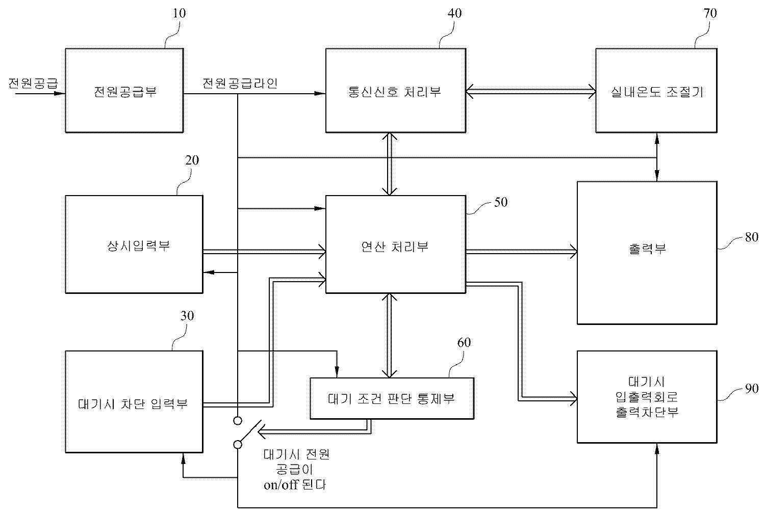
도 1은 본 고안의 보일러 대기 모드 전력 저감장치의 블록도를 도시한다.1 is a block diagram of a boiler standby mode power reduction device of the present invention.
본원고안의 대기 모드 전력 저감장치는 전원 공급부인 SMPS(Switching Mode Power Supply)(10), 기본 입력 센서로서 온도 센서부, 가스 누설 감지부, 과열 감지부, 유량 감지부를 포함하고 치명적으로 고장으로 이어질 수 있는 고장을 감지하는 상시 입력부(20), 저수위 감지부, 송풍기 회전 감지부, 의사염 감지부, 응축수 감지부와 같은 부분의 대기시 전력 입력을 차단하는 대기시 차단 입력부(30), 정상 운전시에는 0.1초 주기로 기본 데이터 및 확장 데이터를 후술하는 연산 처리부(50) 및 실내온도 조절기(70)와 연속 송/수신하고, 대기시에는 2초에 1회 주기로 기본 데이터만 교신하는 통신 신호 처리부(40), 메인 CPU와 서브 CPU로 구성된 연산 제어처리부(50)로서, 실내 조절기 및 외부 네트워크 통신에 의한 운전모드의 변경과 수온 조절을 위한 최적의 연소 열량을 계산하고, 공기공급량을 직접 제어하며, 서브 CPU의 동작 지시와 감시를 담당하는 메인 CPU 및 상기 메인 CPU의 정해진 절차에 따라 연소 신호에 의해 화염 감지부와 가스 밸브 동작을 직접적으로 온/오프하며, 메인 CPU와는 분리된 주요 안전 장치의 확인과 팬 회전수에 따른 급기량과 가스 공급량을 지속적으로 비교 감시하는 서브 CPU로 구성된다. 상기 서브 CPU는 두 개의 올 플래시(All Flash) CPU로 되며, 일반제어부와 연소 안전 제어 기능을 분리하여 상호 견제 감시로 안정성을 강화한다. 또한, 대기 모드 전력 저감장치는 보일러의 대기 조건을 판단하고, 내부 전원공급을 관리하는 부분으로 팬 및 펌프 정지 조건 또는 온수 전용 타이머 예약정지 통파 예방 운전 조건 등의 상태를 판단하여 정상 대기모드의 전환을 행하며, 대기모드에서 불필요한 회로의 전원공급을 차단하는 대기 조건 판단 통제부(60), 100ms 주기로 충전 및 통신을 행하며, 상기 통신 신호 처리부(40)와 매회 데이터의 송수신시 표준 데이터와 확장 데이터를 송수신하며, 셋업 모드 상태가 될 때 상기 확장 데이터에 셋업 데이터를 포함하여 송수신하며, 대기시에는 2초에 1회 주기로 기본 데이터만 교신하는 실내온도 조절기(70), 순환펌프, 비례 제어변, 가스 차단변, 점화기 출력부, 삼방변, 송풍 팬 출력부 등을 포함하고, 보일러가 가동조건이 되어 보일러가 가동될 때 연산처리 제어부(50)의 명령에 의해 전원이 공급되는 출력부(80) 및 연소 정지후 송풍기 팬의 폐가스 방출, 연소로 냉각을 위한 잔류 동작이 끝나면 송풍기 팬과 관련된 입 출력 회로의 전원을 차단하여 대기 전력을 1W로 감소시키는 대기시 입출력 회로 출력 차단부(90)를 포함하는데, 이 대기시 입출력회로 출력 차단부(90)는 염감지 고전압 발생부, 수위 감지 펄스 출력부 및 홀센서 바이어스 출력부의 출력을 차단한다. The standby mode power reduction device of the present application includes a switching mode power supply (SMPS) 10, which is a power supply unit, a temperature sensor unit, a gas leak detector, an overheat detector, a flow detector, as a basic input sensor, and may lead to fatal failure.
상기와 같이 구성된 본 고안의 보일러 대기 모드 전력 저감장치의 동작을 보면, 전원 공급부(10)로부터의 전원공급라인을 통해 통신 신호처리부(40)로 전원이 공급되고, 연산 처리 제어부(50)는 상시 입력부(20) 및 대기시 차단 입력부(30)로부터 입력을 받아서 처리하며, 통신 신호 처리부(40) 및 대기조건 판단 통제부(60)와 신호를 송수신하며, 출력부(80) 및 대기시 입출력 회로 출력 차단부(90)로 신호를 출력한다. 대기 조건 판단 통제부(60)는 연산 처리 제어부(50)로부터의 명령에 따라 대기시 전원 공급을 온/오프 한다. 대기시 전원 공급의 온/오프에 따라 대기시 입출력 회로 출력 차단부(90)의 전원 또한 온/오프된다. Referring to the operation of the boiler standby mode power reduction device of the present invention configured as described above, power is supplied to the communication
도 2는 도 1의 전원공급부의 상세 회로도를 도시한다. FIG. 2 shows a detailed circuit diagram of the power supply unit of FIG. 1.
도 2에 있어서 본 고안과 직접적인 관련이 있는 부분에 대해서만 설명하며, 본 고안의 요지를 흐릴 수 있는 그 밖의 부분에 대해서는 그 설명을 생략한다. In FIG. 2, only parts directly related to the present invention will be described, and other descriptions that may obscure the subject matter of the present invention will be omitted.
도 2의 A부분에 있어서, BD(브리지 다이오드)1을 거쳐서 AC 전원이 DC 전원으로 변경되며, C21 및 C22를 거쳐서 전원상의 리플, 즉 맥동을 평활하게 함으로써 완전한 DC 전원으로 변환한다. 도면에서 B 부분은 AC 220V(185 ~ 265V AC) 전원 입력을 받아서 60W급의 멀티출력(DC 24V, 12V)를 만드는 SMPS 회로이다. 저항 R80 은 보통 전원 출력의 효율을 80%로 제한하기 위해 사용된다(이는 TOP245Y SMPS IC 칩 사양에서 미리 결정된 것임). 저항 R33 및 R42는 A 부분을 통하여 생선된 DC라인에 전류된 450V 이상의 서지 전압으로부터 TOP245Y를 보호하기 위하여 사용되며, 495V AC 이상의 전원이 입력되는 상태에서는 TOP245Y의 스위칭 동작을 정지시키기 위한 DC 라인 센싱용 저항으로 사용된다. 다이오드 D21, D14, 및 커패시터 C15는 모든 동작 조건에서 TOP245Y 7번핀 드레인에 걸리는 전압을 700V이하로 발생하는 누설 인덕턴스(코일에서 발생하는 역기전력)로부터 보호하기 위한 소자로 사용된다. In part A of FIG. 2, the AC power supply is changed to the DC power supply via the BD (bridge diode) 1, and is converted to a complete DC power supply by smoothing the ripple, that is, the pulsation, on the power supply via C21 and C22. In the figure, part B is an SMPS circuit that receives an AC 220V (185 to 265V AC) power input and produces 60W multi output (DC 24V, 12V). Resistor R80 is usually used to limit the efficiency of the power output to 80% (which is predetermined in the TOP245Y SMPS IC chip specification). The resistors R33 and R42 are used to protect the TOP245Y from surge voltages of 450V and higher that are currentd on the DC line that is fed through the A part, and for DC line sensing to stop the switching operation of TOP245Y when a power supply of 495V AC or higher is input. Used as a resistor. Diodes D21, D14, and capacitor C15 are used to protect the voltage across the
C 부분은 콘센트로부터 메인 전원 220V를 PCB 보드에 공급하는 부분이며, 250V/3A의 퓨즈를 이용하여 과전류를 차단하며, DSA 바리스터를 사요아여 낙뢰 등의 고전압으로부터 회로를 보호한다. The C part supplies the main power 220V to the PCB board from the outlet, and cuts off the overcurrent by using the 250V / 3A fuse and protects the circuit from high voltage such as lightning by using DSA varistor.
한편, C16, TR2, C31은 TOP245YDML 불안정 주파수(노이즈) 특성에 대하여 EMI 필터용 부품으로서 사용된다. On the other hand, C16, TR2, and C31 are used as components for EMI filters with respect to TOP245YDML unstable frequency (noise) characteristics.
본 고안에 의하면, 기존의 방식에 비해 대기시 소모 전력을 1/3로 저감되며, (보통 3W에서 1W로) 이를 통해 실제 연소 가동시간이 짧고 긴 대기시간을 가진 보일러의 경우 전력 요금 절감, 저발열, 소형화 친 환경성을 증진 시킬 수 있는 보일러의 대기 시간 전력 저감 장치를 제공할 수 있는 효과를 얻을 수 있다. According to the present invention, the standby power consumption is reduced by one third compared to the conventional method (usually from 3W to 1W), and thus, the boiler has a shorter operating time and a lower standby time. It is possible to obtain an effect that can provide a standby power reduction device of the boiler that can improve the heat generation, miniaturization and eco-friendliness.
지금까지 본 고안의 일 실시예를 도면을 참조로 하여 기술하였으나, 본 고안은 이에 한정되지 않으며, 이하의 부속 청구범위의 사상 및 영역을 일탈하지 않는 범위 내에서 당업자에 의해 여러 가지로 수정 및 변형실시될 수 있으며, 이와 같은 수정 및 변형은 본 고안의 영역 내에 있는 것으로 해석되어야 할 것이다. One embodiment of the present invention has been described with reference to the drawings, but the present invention is not limited thereto, and various modifications and variations are made by those skilled in the art without departing from the spirit and scope of the appended claims below. Such modifications and variations are intended to be interpreted as being within the scope of the present invention.
도 1은 본 고안의 보일러 대기 모드 전력 저감장치의 블록도를 도시한다.1 is a block diagram of a boiler standby mode power reduction device of the present invention.
도 2는 도 1의 전원공급부의 상세 회로도를 도시한다. FIG. 2 shows a detailed circuit diagram of the power supply unit of FIG. 1.
*도면의 주요 부분에 대한 부호의 설명** Description of the symbols for the main parts of the drawings *
10: 전원공급부 20: 상기 입력부10: power supply unit 20: the input unit
30: 대기시 차단 입력부 40: 통신신호 처리부30: standby block input unit 40: communication signal processing unit
50: 연산 처리 제어부 60: 대기 조건 판단 통제부50: arithmetic processing control unit 60: waiting condition determination control unit
70: 실내온도 조절기 80: 출력부70: room temperature controller 80: output unit
90: 대기시 입출력 회로 출력 차단부90: I / O circuit output disconnection unit during standby
Claims (3)
Priority Applications (1)
| Application Number | Priority Date | Filing Date | Title |
|---|---|---|---|
| KR2020090016552U KR200460912Y1 (en) | 2009-12-18 | 2009-12-18 | Apparatus for Reducig Waiting time of Boiler |
Applications Claiming Priority (1)
| Application Number | Priority Date | Filing Date | Title |
|---|---|---|---|
| KR2020090016552U KR200460912Y1 (en) | 2009-12-18 | 2009-12-18 | Apparatus for Reducig Waiting time of Boiler |
Publications (2)
| Publication Number | Publication Date |
|---|---|
| KR20110006417U KR20110006417U (en) | 2011-06-24 |
| KR200460912Y1 true KR200460912Y1 (en) | 2012-06-14 |
Family
ID=46607745
Family Applications (1)
| Application Number | Title | Priority Date | Filing Date |
|---|---|---|---|
| KR2020090016552U KR200460912Y1 (en) | 2009-12-18 | 2009-12-18 | Apparatus for Reducig Waiting time of Boiler |
Country Status (1)
| Country | Link |
|---|---|
| KR (1) | KR200460912Y1 (en) |
Citations (4)
| Publication number | Priority date | Publication date | Assignee | Title |
|---|---|---|---|---|
| KR100324744B1 (en) | 1999-02-04 | 2002-02-20 | 구자홍 | Apparatus and method for saving stand-by electric power |
| KR200345177Y1 (en) | 2003-12-10 | 2004-03-16 | 이기석 | Apparatus for Preventing the Inrush Current in the Refrigerator |
| KR100836821B1 (en) | 2007-02-16 | 2008-06-12 | 삼성전자주식회사 | Air conditioner system for reducing electric power on waiting mode and operating method thereof |
| KR20090070335A (en) * | 2007-12-27 | 2009-07-01 | 린나이코리아 주식회사 | Communication controlling apparatus of boiler remote controller for reducing standby powers and its controlling method thereof |
-
2009
- 2009-12-18 KR KR2020090016552U patent/KR200460912Y1/en active IP Right Grant
Patent Citations (4)
| Publication number | Priority date | Publication date | Assignee | Title |
|---|---|---|---|---|
| KR100324744B1 (en) | 1999-02-04 | 2002-02-20 | 구자홍 | Apparatus and method for saving stand-by electric power |
| KR200345177Y1 (en) | 2003-12-10 | 2004-03-16 | 이기석 | Apparatus for Preventing the Inrush Current in the Refrigerator |
| KR100836821B1 (en) | 2007-02-16 | 2008-06-12 | 삼성전자주식회사 | Air conditioner system for reducing electric power on waiting mode and operating method thereof |
| KR20090070335A (en) * | 2007-12-27 | 2009-07-01 | 린나이코리아 주식회사 | Communication controlling apparatus of boiler remote controller for reducing standby powers and its controlling method thereof |
Also Published As
| Publication number | Publication date |
|---|---|
| KR20110006417U (en) | 2011-06-24 |
Similar Documents
| Publication | Publication Date | Title |
|---|---|---|
| KR101084109B1 (en) | Power saving multiconcent for fire prevention | |
| AU2007327557A1 (en) | Power supply control device | |
| KR100929818B1 (en) | Power saving plug socket for fire prevention | |
| KR101738618B1 (en) | Multiconcent and control method thereof | |
| KR20130003254A (en) | Apparatus for reducing standby power consumption | |
| KR101295761B1 (en) | The apparatus of control to isolate a standby power | |
| KR200460912Y1 (en) | Apparatus for Reducig Waiting time of Boiler | |
| JP2010199762A (en) | Electronic type switch with triac control-stabilized power supply circuit | |
| WO2012155337A1 (en) | Protection circuit of dc brush motor | |
| EP2180263B1 (en) | Refrigeration cycle apparatus as well as air conditioner and water heater having the same | |
| CN214199229U (en) | Gas-electricity shared energy-saving water outlet device | |
| JP2004215481A (en) | Energy saving control terminal | |
| KR101116916B1 (en) | Standby power breakiing device | |
| KR20110017949A (en) | Apparatus and method for saving stand-by electric power | |
| KR101048035B1 (en) | Receptacle controller for cutting off standby power | |
| JP2010004613A (en) | Power supply device | |
| TWM560742U (en) | Standby circuit, and outlet, plug, and device having the same | |
| KR200363480Y1 (en) | Power saving type multi-tapconcent by sensing a load current | |
| JP2005065495A (en) | Mechanism for disconnecting electronic device from power supply | |
| CN211575559U (en) | Water flow detection circuit, water mixing device, electric control device and electric water heater thereof | |
| KR200414600Y1 (en) | multi-tap device for computer | |
| JP4733883B2 (en) | Cogeneration system controller | |
| US20220029451A1 (en) | Devices, systems, and methods for reducing standby power consumption | |
| KR200426798Y1 (en) | Device for automatically controlling a temperature | |
| KR20090113402A (en) | Apparatus and method for reducing standby power consumption |
Legal Events
| Date | Code | Title | Description |
|---|---|---|---|
| A201 | Request for examination | ||
| E902 | Notification of reason for refusal | ||
| E701 | Decision to grant or registration of patent right | ||
| REGI | Registration of establishment | ||
| FPAY | Annual fee payment |
Payment date: 20150601 Year of fee payment: 4 |
|
| FPAY | Annual fee payment |
Payment date: 20160527 Year of fee payment: 5 |
|
| FPAY | Annual fee payment |
Payment date: 20170516 Year of fee payment: 6 |
|
| FPAY | Annual fee payment |
Payment date: 20180604 Year of fee payment: 7 |
|
| FPAY | Annual fee payment |
Payment date: 20190528 Year of fee payment: 8 |