KR200441663Y1 - Antenna case - Google Patents
Antenna case Download PDFInfo
- Publication number
- KR200441663Y1 KR200441663Y1 KR2020080001198U KR20080001198U KR200441663Y1 KR 200441663 Y1 KR200441663 Y1 KR 200441663Y1 KR 2020080001198 U KR2020080001198 U KR 2020080001198U KR 20080001198 U KR20080001198 U KR 20080001198U KR 200441663 Y1 KR200441663 Y1 KR 200441663Y1
- Authority
- KR
- South Korea
- Prior art keywords
- antenna
- case
- fixing frame
- display
- antenna case
- Prior art date
- Legal status (The legal status is an assumption and is not a legal conclusion. Google has not performed a legal analysis and makes no representation as to the accuracy of the status listed.)
- Expired - Lifetime
Links
- 230000000007 visual effect Effects 0.000 claims abstract description 12
- 239000000758 substrate Substances 0.000 claims description 8
- 238000000034 method Methods 0.000 claims description 6
- NJPPVKZQTLUDBO-UHFFFAOYSA-N novaluron Chemical compound C1=C(Cl)C(OC(F)(F)C(OC(F)(F)F)F)=CC=C1NC(=O)NC(=O)C1=C(F)C=CC=C1F NJPPVKZQTLUDBO-UHFFFAOYSA-N 0.000 claims description 5
- 230000000694 effects Effects 0.000 abstract description 6
- 238000010586 diagram Methods 0.000 description 2
- 230000007613 environmental effect Effects 0.000 description 1
- 239000000463 material Substances 0.000 description 1
Images


Classifications
-
- H—ELECTRICITY
- H01—ELECTRIC ELEMENTS
- H01Q—ANTENNAS, i.e. RADIO AERIALS
- H01Q1/00—Details of, or arrangements associated with, antennas
- H01Q1/12—Supports; Mounting means
-
- H—ELECTRICITY
- H01—ELECTRIC ELEMENTS
- H01Q—ANTENNAS, i.e. RADIO AERIALS
- H01Q1/00—Details of, or arrangements associated with, antennas
- H01Q1/12—Supports; Mounting means
- H01Q1/22—Supports; Mounting means by structural association with other equipment or articles
- H01Q1/24—Supports; Mounting means by structural association with other equipment or articles with receiving set
- H01Q1/241—Supports; Mounting means by structural association with other equipment or articles with receiving set used in mobile communications, e.g. GSM
-
- H—ELECTRICITY
- H01—ELECTRIC ELEMENTS
- H01Q—ANTENNAS, i.e. RADIO AERIALS
- H01Q1/00—Details of, or arrangements associated with, antennas
- H01Q1/40—Radiating elements coated with or embedded in protective material
-
- H—ELECTRICITY
- H01—ELECTRIC ELEMENTS
- H01Q—ANTENNAS, i.e. RADIO AERIALS
- H01Q1/00—Details of, or arrangements associated with, antennas
- H01Q1/44—Details of, or arrangements associated with, antennas using equipment having another main function to serve additionally as an antenna, e.g. means for giving an antenna an aesthetic aspect
Landscapes
- Engineering & Computer Science (AREA)
- Computer Networks & Wireless Communication (AREA)
- Support Of Aerials (AREA)
Abstract
본 고안은 안테나 케이스에 관한 것으로, 특히 미적(美的)으로 처리되어 시각적·전시적 효과를 얻을 수 있는 안테나 케이스에 관한 것이다. 본 고안에 따른 안테나 케이스는 케이스 본체의 테두리에 일체로 형성되는 고정틀과 상기 고정틀에 끼워져 시각적 효과를 발생하는 디스플레이를 포함한다. 바람직하게, 상기 고정틀은 본체의 테두리에 연이어 제공되며, 그 일측에는 디스플레이가 출입할 수 있는 틈이 형성된다.The present invention relates to an antenna case, and more particularly to an antenna case that can be aesthetically processed to obtain a visual and exhibition effect. The antenna case according to the present invention includes a fixing frame integrally formed on the edge of the case body and a display which is fitted to the fixing frame to generate a visual effect. Preferably, the fixing frame is provided in succession to the rim of the main body, one side of the fixing frame is formed with a gap through which the display can enter.
안테나, 케이스, 고정틀, 디스플레이, 본체 Antenna, case, fixing frame, display, body
Description
본 고안은 안테나 케이스에 관한 것으로, 특히 미적(美的)으로 처리되어 시각적·전시적 효과를 얻을 수 있는 안테나 케이스에 관한 것이다.The present invention relates to an antenna case, and more particularly to an antenna case that can be aesthetically processed to obtain a visual and exhibition effect.
통상적으로, RF 중계용 안테나는 레이돔(RADOME) 또는 기타 형태의 덮개를 포함하는 안테나 케이스에 내장된다. 안테나로서는 대체로 패치 또는 패치 어레이 안테나가 적용되지만, 다른 종류의 안테나가 적용될 수도 있다. 전력 컨넥터가 상기 안테나 케이스로부터 돌출되고, 외부 전력이 안테나 소자에 공급됨으로써 안테나가 동작하도록 되어 있다.Typically, the RF relay antenna is embedded in an antenna case that includes a radome or other type of cover. As the antenna, a patch or patch array antenna is generally applied, but other antennas may be applied. The power connector protrudes from the antenna case and the external power is supplied to the antenna element to operate the antenna.
안테나 케이스는 안테나를 외부 환경으로부터 보호하는 역할을 하는 것이다. 따라서 기능적으로는 안테나를 내장하고, 내장된 안테나에 전력을 공급할 수 있는 형태로써 족하다. 그러나 그 외형이 단순히 기계적인 형태로 처리되어, 보는 이로 하여금 삭막감 내지 거부감이 느껴지도록 되어 있다.The antenna case serves to protect the antenna from the external environment. Therefore, functionally enough to form a built-in antenna and to supply power to the built-in antenna. However, the appearance is simply processed in a mechanical form, so that the viewer feels cutback or rejection.
이것은 현대에 이르러 물품의 외형에 대한 환경친화성 또는 예술적/미적 처리에 관심이 집중되는 것과는 반대의 입장에 있는 것이다. 이에 안테나 케이스에 있어서도 외형의 미적 처리, 적어도 거부감이 없는 외형적 처리가 필요하게 되는 것이다.This is in opposition to the focus on the environmental friendliness or the artistic / aesthetic treatment of the appearance of goods in modern times. In the antenna case, therefore, the aesthetic processing of the appearance and at least the external processing without the sense of rejection are required.
본 고안은 종래 안테나 케이스의 문제점을 해결하고자 제안된 것이다. 본 고안의 목적은 미적으로 처리되어 시각적·전시적 효과를 얻을 수 있는 안테나 케이스를 제공하고자 하는 것이다. 본 고안의 다른 목적은 미적 처리를 수시로 다르게 하여 다양성을 제공할 수 있는 안테나 케이스를 제공하고자 하는 것이다.The present invention is proposed to solve the problem of the conventional antenna case. An object of the present invention is to provide an antenna case that can be aesthetically processed to obtain a visual and exhibition effect. Another object of the present invention is to provide an antenna case that can provide variety by varying the aesthetic process from time to time.
본 고안에 따른 안테나 케이스는:Antenna case according to the present invention is:
안테나 소자가 내장되는 안테나 케이스 본체와; An antenna case body in which an antenna element is embedded;
상기 안테나 케이스 본체의 테두리에 일체로 형성되는 고정틀과; A fixing frame integrally formed on an edge of the antenna case body;
상기 고정틀에 끼워져 시각적 효과를 발생하는 디스플레이;A display fitted to the fixing frame to generate a visual effect;
를 포함한다.It includes.
바람직하게, 상기 고정틀은 본체의 테두리에 연이어 제공되며, 그 일측에는 디스플레이가 출입할 수 있는 틈이 형성된다.Preferably, the fixing frame is provided in succession to the rim of the main body, one side of the fixing frame is formed with a gap through which the display can enter.
본 고안의 안테나 케이스는 고정틀에 끼워져 시각적 효과를 발생하는 디스플레이를 포함하여 구성된다. 따라서 안테나 케이스의 단순 기계적 이미지 보다는 미 적으로 처리된 시각적·전시적 효과를 얻을 수 있다. 또한 디스플레이를 수시로 교체함으로써 시각적인 다양성 효과를 얻을 수 있다.Antenna case of the present invention is configured to include a display that is fitted to the fixed frame to produce a visual effect. Therefore, the aesthetically processed visual and exhibition effect can be obtained rather than the simple mechanical image of the antenna case. You can also change the display from time to time to get a visual diversity effect.
본 고안의 특징과 효과들은, 이하에서 첨부도면을 참조하여 설명하는 실시예를 통하여 명백해질 것이다.Features and effects of the present invention will become apparent from the following description with reference to the accompanying drawings.
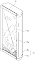
도 1 및 도 2를 참조하면, 본 고안의 실시예에 따른 안테나 케이스는 부호 10으로 나타낸다. 상기 안테나 케이스(10)는 케이스 본체(11)와 고정틀(12) 및 디스플레이(13)으로 구성된다.1 and 2, the antenna case according to an embodiment of the present invention is shown by the
상기 케이스 본체(11)는 안테나 소자를 포함하는 안테나 장치(14)를 내장하며, 안테나 소자에 전력을 공급하기 위한 컨넥터(15)가 케이스 본체(11)로부터 돌출되어 있다. 상기 안테나 장치(14)로서 패치 어레이 안테나를 도시하였으나, 본 고안이 안테나 장치(14)의 종류에 한정되는 것은 아니다. 한편, 안테나 장치(14)와 컨넥터(15) 간의 접속은, 알려진 기술을 이용하며 본 고안에서 특징되는 것도 아니므로, 상세한 설명은 하지 않는다.The
상기 고정틀(12)은 상기 케이스 본체(11)의 전면 테두리에 형성된다. 상기 고정틀(12)은 본체(11)의 전면 테두리에 일체로 성형되거나, 별도로 제공되어 접합 또는 체결 등의 방법으로 일체화된다. 이 고정틀(12)은 디스플레이(13)를 고정하기 위한 수단으로, 대향하는 양측에 형성될 수도 있다. The
디스플레이(13)의 견고한 고정을 위하여, 상기 고정틀(12)은 본체의 테두리에 연이어 제공된다. 이 때, 고정틀(12)의 일측에는 디스플레이(13)가 출입할 수 있는 틈(16)이 형성된다. 이 틈(16)을 통하여 디스플레이(13)가 출입할 수 있으며, 따라서 디스플레이(13)의 교체 및 보수가 가능하다.In order to securely fasten the
상기 디스플레이(13)는 상기 고정틀(12)에 끼워져 시각적 효과를 발생하는 것이면 충분하며, 디스플레이의 종류나 재료는 한정되지 않는다. 다만, 상기 고정틀(12)의 틈(12)을 출입할 수 있는 플레이트형이면 된다.It is sufficient that the
도 1 및 도 2에서, 본 실시예의 안테나 케이스(10)의 케이스 본체(11)는 벽형 기판(17)과 상기 기판(17) 전방에 설치 고정된 안테나 덮개(18)로 구성된 것이고, 상기 고정틀(12)이 안테나 덮개(18)의 전면 테두리에 제공된 것을 예시하였다.1 and 2, the
다만 도 3에서 예시된 바, 다른 실시예에서 케이스 본체(11a)는 바닥형 기판(17a)과 상기 기판(17a) 상방에 설치 고정된 안테나 덮개(18a)로 구성된 것이고, 상기 고정틀(12)이 안테나 덮개(18a)의 전면 테두리에 제공된 것일 수도 있다.However, as illustrated in FIG. 3, in another embodiment, the
어떤 경우이든, 디스플레이(13)는 고정틀(12)에 고정되어, 전방을 향하여 미적으로 처리된 시각적·전시적 이미지를 제공할 수 있다.In any case, the
도 4 및 도 5를 참조하면, 본 고안의 안테나 케이스는 받침대(20)를 이용하여 설치되거나 고정용 폴 등을 이용하여 설치될 수 있다. 받침대(20)의 경우 안테나 케이스 본체(11)의 측면 돌기에 대응하는 홈(21)을 형성하는 것이 좋다. 부호 22는 고정용 폴에 설치할 때 사용되는 고정용 브래킷이다.4 and 5, the antenna case of the present invention may be installed using the
도 1은 본 고안의 실시예에 따른 안테나 케이스의 사시도.1 is a perspective view of an antenna case according to an embodiment of the present invention.
도 2는 도 1의 분해 사시도.2 is an exploded perspective view of FIG.
도 3은 본 고안에 따른 다른 실시예의 사시도.3 is a perspective view of another embodiment according to the present invention.
도 4는 도 1의 안테나 케이스의 사용상태도.4 is a state diagram used in the antenna case of FIG.
도 5는 도 3의 안테나 케이스의 사용상태도.5 is a state diagram used in the antenna case of FIG.
<도면의 주요부분에 대한 부호의 설명><Description of the symbols for the main parts of the drawings>
10. 안테나 케이스 11. 케이스 본체10.
12. 고정틀 13. 디스플레이12. Fixture 13. Display
16. 틈16. Break
Claims (6)
Priority Applications (1)
| Application Number | Priority Date | Filing Date | Title |
|---|---|---|---|
| KR2020080001198U KR200441663Y1 (en) | 2008-01-25 | 2008-01-25 | Antenna case |
Applications Claiming Priority (1)
| Application Number | Priority Date | Filing Date | Title |
|---|---|---|---|
| KR2020080001198U KR200441663Y1 (en) | 2008-01-25 | 2008-01-25 | Antenna case |
Publications (1)
| Publication Number | Publication Date |
|---|---|
| KR200441663Y1 true KR200441663Y1 (en) | 2008-09-01 |
Family
ID=41646234
Family Applications (1)
| Application Number | Title | Priority Date | Filing Date |
|---|---|---|---|
| KR2020080001198U Expired - Lifetime KR200441663Y1 (en) | 2008-01-25 | 2008-01-25 | Antenna case |
Country Status (1)
| Country | Link |
|---|---|
| KR (1) | KR200441663Y1 (en) |
-
2008
- 2008-01-25 KR KR2020080001198U patent/KR200441663Y1/en not_active Expired - Lifetime
Similar Documents
| Publication | Publication Date | Title |
|---|---|---|
| US10884276B2 (en) | Display device with simplified appearance structure and improved coupling arrangement | |
| US8879139B2 (en) | Display mirror assembly | |
| US9696573B2 (en) | Display module and liquid crystal display device including the same | |
| JP2019135563A (en) | Display mirror assembly | |
| US20200014881A1 (en) | Television Frame | |
| TW200724995A (en) | Color filters for a rollable display | |
| US20160223866A1 (en) | Display apparatus | |
| KR20170049745A (en) | Display apparatus | |
| US8959740B2 (en) | Shape adjustment system | |
| KR200441663Y1 (en) | Antenna case | |
| KR20180025776A (en) | Display apparatus | |
| CN104076540A (en) | Display without frame | |
| US9303849B1 (en) | Flat panel concealment apparatus with a graphic and ambient light method | |
| CN105068406A (en) | Smart watch | |
| TWI664880B (en) | Display device | |
| CN206021225U (en) | A kind of fastening structure of display casing | |
| CN105915829A (en) | Display terminal | |
| KR20160001554U (en) | A roll screen | |
| CN103731620A (en) | Integrated liquid crystal display television | |
| TW200641460A (en) | Display device | |
| KR101703035B1 (en) | Vehicle Seat Equipped with Detachable Pocket | |
| KR20150119644A (en) | Detachable picture frame album | |
| US20210216113A1 (en) | Display device | |
| KR20120012518A (en) | Refrigerator decoration | |
| US20170227706A1 (en) | Light-Source Device and Display Apparatus |
Legal Events
| Date | Code | Title | Description |
|---|---|---|---|
| A201 | Request for examination | ||
| A302 | Request for accelerated examination | ||
| UA0108 | Application for utility model registration |
Comment text: Application for Utility Model Registration Patent event code: UA01011R08D Patent event date: 20080125 |
|
| UA0201 | Request for examination | ||
| UA0301 | Request for accelerated examination |
Comment text: [Request for Accelerated Examination] Document of Request for Examination(Accelerated Examination) Patent event date: 20080125 Patent event code: UA03012R01D |
|
| E902 | Notification of reason for refusal | ||
| UE0902 | Notice of grounds for rejection |
Comment text: Notification of reason for refusal Patent event code: UE09021S01D Patent event date: 20080417 |
|
| E701 | Decision to grant or registration of patent right | ||
| UE0701 | Decision of registration |
Patent event date: 20080808 Comment text: Decision to Grant Registration Patent event code: UE07011S01D |
|
| REGI | Registration of establishment | ||
| UR0701 | Registration of establishment |
Patent event date: 20080826 Patent event code: UR07011E01D Comment text: Registration of Establishment |
|
| UR1002 | Payment of registration fee |
Start annual number: 1 End annual number: 3 Payment date: 20080826 |
|
| UG1601 | Publication of registration | ||
| UR1001 | Payment of annual fee |
Payment date: 20110531 Start annual number: 4 End annual number: 4 |
|
| FPAY | Annual fee payment |
Payment date: 20120826 Year of fee payment: 5 |
|
| UR1001 | Payment of annual fee |
Payment date: 20120826 Start annual number: 5 End annual number: 5 |
|
| FPAY | Annual fee payment |
Payment date: 20130826 Year of fee payment: 6 |
|
| UR1001 | Payment of annual fee |
Payment date: 20130826 Start annual number: 6 End annual number: 6 |
|
| FPAY | Annual fee payment |
Payment date: 20150826 Year of fee payment: 8 |
|
| UR1001 | Payment of annual fee |
Payment date: 20150826 Start annual number: 8 End annual number: 8 |
|
| FPAY | Annual fee payment |
Payment date: 20160826 Year of fee payment: 9 |
|
| UR1001 | Payment of annual fee |
Payment date: 20160826 Start annual number: 9 End annual number: 9 |
|
| FPAY | Annual fee payment |
Payment date: 20170828 Year of fee payment: 10 |
|
| UR1001 | Payment of annual fee |
Payment date: 20170828 Start annual number: 10 End annual number: 10 |
|
| EXPY | Expiration of term | ||
| UC1801 | Expiration of term |
Termination category: Expiration of duration Termination date: 20180725 |