KR200427770Y1 - Snow Spill Discharge Device for Sand Sprayer - Google Patents
Snow Spill Discharge Device for Sand Sprayer Download PDFInfo
- Publication number
- KR200427770Y1 KR200427770Y1 KR2020060018531U KR20060018531U KR200427770Y1 KR 200427770 Y1 KR200427770 Y1 KR 200427770Y1 KR 2020060018531 U KR2020060018531 U KR 2020060018531U KR 20060018531 U KR20060018531 U KR 20060018531U KR 200427770 Y1 KR200427770 Y1 KR 200427770Y1
- Authority
- KR
- South Korea
- Prior art keywords
- storage tank
- sand
- snow
- storage
- base plate
- Prior art date
- Legal status (The legal status is an assumption and is not a legal conclusion. Google has not performed a legal analysis and makes no representation as to the accuracy of the status listed.)
- Expired - Fee Related
Links
Images


Classifications
-
- E—FIXED CONSTRUCTIONS
- E01—CONSTRUCTION OF ROADS, RAILWAYS, OR BRIDGES
- E01C—CONSTRUCTION OF, OR SURFACES FOR, ROADS, SPORTS GROUNDS, OR THE LIKE; MACHINES OR AUXILIARY TOOLS FOR CONSTRUCTION OR REPAIR
- E01C11/00—Details of pavings
- E01C11/24—Methods or arrangements for preventing slipperiness or protecting against influences of the weather
- E01C11/245—Methods or arrangements for preventing slipperiness or protecting against influences of the weather for preventing ice formation or for loosening ice, e.g. special additives to the paving material, resilient coatings
-
- E—FIXED CONSTRUCTIONS
- E01—CONSTRUCTION OF ROADS, RAILWAYS, OR BRIDGES
- E01H—STREET CLEANING; CLEANING OF PERMANENT WAYS; CLEANING BEACHES; DISPERSING OR PREVENTING FOG IN GENERAL CLEANING STREET OR RAILWAY FURNITURE OR TUNNEL WALLS
- E01H10/00—Improving gripping of ice-bound or other slippery traffic surfaces, e.g. using gritting or thawing materials ; Roadside storage of gritting or solid thawing materials; Permanently installed devices for applying gritting or thawing materials; Mobile apparatus specially adapted for treating wintry roads by applying liquid, semi-liquid or granular materials
- E01H10/005—Permanently-installed devices for applying gritting or thawing materials, e.g. for spreading grit, for spraying de-icing liquids
Landscapes
- Engineering & Computer Science (AREA)
- Architecture (AREA)
- Civil Engineering (AREA)
- Structural Engineering (AREA)
- Road Paving Machines (AREA)
Abstract
본 고안은 모래살포기의 제설용 저장물 배출장치에 관한 것으로서, 베이스플레이트의 상부에 모래 또는 염화칼슘 등의 제설용 저장물을 저장하는 저장탱크가 구비되고 상기 저장탱크의 출구에 구성되어 제설용 저장물의 배출시 이를 인도하는 배출슈트가 구비된 모래살포기에 있어서, 상기 베이스플레이트 상부에 위치되고 상기 저장탱크의 전방에 구성되면서 저장탱크와 연결된 승강부재; 상기 베이스플레이트 상부에 위치되고 상기 저장탱크의 후방에 구성되면서 저장탱크와 힌지 결합하는 링크부재;로 구성되어 승강부재 및 링크부재를 통해 저장탱크의 경사각 조절이 됨으로써 저장탱크 내부에 저장되어 있는 제설용 저장물의 배출이 용이할 뿐만 아니라 제설용 저장물의 배출량을 조절할 수 있으면서 제설용 저장물을 완전하게 배출할 수 있는 효과가 있다. The present invention relates to a storage device for removing snow for sand spreader, comprising a storage tank for storing snow for storage of sand or calcium chloride on the base plate and configured at the outlet of the storage tank, A sand spreader having a discharge chute for guiding it during discharge, the sand spreader comprising: an elevating member positioned above the base plate and connected to the storage tank while being configured in front of the storage tank; A link member positioned above the base plate and configured to be hinged with the storage tank while being configured at the rear of the storage tank; and configured to be inclined by the inclined angle of the storage tank through the elevating member and the link member and stored in the storage tank. Not only is the discharge of the stock easy to control, but the control of the amount of snow removing stock can have the effect of completely discharging the stock for snow removing.
모래, 모래살포기, 승강부재, 링크부재, 저장탱크, 염화칼슘, 제설 Sand, sand spreader, lifting member, link member, storage tank, calcium chloride, snow removal
Description
도 1은 본 고안에 따른 모래살포기의 제설용 저장물 배출장치를 도시한 측면도. 1 is a side view showing a storage device for removing the snow of the sand spreader according to the present invention.
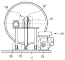
도 2는 본 고안에 따른 모래살포기의 제설용 저장물 배출장치를 도시한 정면도.Figure 2 is a front view showing a storage device for removing snow for sand spreader according to the present invention.
도 3은 본 고안에 따른 모래살포기의 제설용 저장물 배출장치의 이송스크류 를 도시한 단면도.Figure 3 is a cross-sectional view showing a transfer screw of the storage device for removing snow for sand spreader according to the present invention.
도 4는 본 고안에 따른 모래살포기의 제설용 저장물 배출장치의 작동상태도.Figure 4 is an operating state of the storage device for removing the snow of the sand spreader according to the present invention.
도 5는 본 고안에 따른 모래살포기의 제설용 저장물 배출장치의 장착 상태도.Figure 5 is a mounting state of the storage device for removing the snow of the sand spreader according to the present invention.
< 도면의 주요 부분에 대한 부호의 설명 > <Description of Symbols for Main Parts of Drawings>
10 : 베이스플레이트 20 : 승강부재 10: base plate 20: lifting member
30 : 링크부재 32 : 지지체 30
34 : 연결링크 40 : 저장탱크 34: link 40: storage tank
42 : 이송스크류 50 : 배출슈트 42: transfer screw 50: discharge chute
60 : 살포기 70 : 공급슈트 60: spreader 70: supply chute
90 : 브라켓트 90: bracket
본 고안은 모래살포기의 제설용 저장물 배출장치에 관한 것으로서, 보다 상세하게는 모래살포기에 설치되어 저장탱크에 저장되어 결빙된 노면에 살포하는 모래 또는 염화칼슘 등을 보다 용이하게 배출할 수 있도록 하는 제설용 저장물 배출장치에 관한 것이다. The present invention relates to a storage device for removing snow from the sand spreader, and more particularly, to install sand or calcium chloride, which is installed in the sand spreader and stored in a storage tank, to spray on the frozen road. A storage discharge device for the present invention.
일반적으로, 동절기에는 눈 또는 비에 의해 결빙된 노면의 미끄럼 방지를 위하여 모래 또는 염화칼슘 등을 살포하고 있으며, 이러한 노면의 미끄럼 방지를 위한 살포방법은 트럭의 적재함에 자동 살포장치를 장착하여 살포하는 방법이 주로 사용되고 있다.In general, in the winter season, sand or calcium chloride is sprayed to prevent slippage of the road surface frozen by snow or rain, and the spraying method for preventing slippage of the road surface is equipped with an automatic spraying device in a truck loading box. This is mainly used.
종래의 자동 살포장치는 모래 또는 염화칼슘 등을 적재하는 호퍼; 호퍼의 하단에 연결 설치되어, 모래 또는 염화칼슘 등을 이송하는 이송유닛; 이송유닛과 연결 설치되어, 이송유닛에 의해 공급된 모래를 노면에 살포하는 살포유닛으로 이루어진다.Conventional automatic spraying device is a hopper for loading sand or calcium chloride; A transfer unit connected to the bottom of the hopper to transfer sand or calcium chloride; It is connected to the transfer unit and consists of a spreading unit for spraying the sand supplied by the transfer unit on the road surface.
그러나 상기와 같은 자동 살포장치는 대부분 호퍼의 형상이 상광하협 구조를 지니고 있어, 모래 또는 염화칼슘 등과 같은 제설용 저장물이 호퍼의 하단에 위치한 이송유닛으로 원활히 공급되지 못하는 문제점이 있다. However, the automatic spreading device as described above has the structure of the hopper is usually the shape of the upper and lower narrow, there is a problem that the storage for snow removal, such as sand or calcium chloride is not smoothly supplied to the transfer unit located at the bottom of the hopper.
특히, 호퍼에 염화칼슘을 적재할 경우 공기 중의 수분에 의해 염화칼슘이 호 퍼에 점착되어 그 공급상태가 더욱 불량해지는 단점이 있다.In particular, when calcium chloride is loaded into the hopper, calcium chloride adheres to the hopper due to moisture in the air, and thus, the supply state thereof becomes more poor.
그리고 최근에는 모래 또는 염화칼슘과 같은 재료를 일정의 비율로 혼합하여 사용하는 경우가 많으며, 고체 재료의 살포뿐 아니라 액상의 염화물을 살포하기도 한다. 이러한 경우 자동 살포장치의 호퍼에 각 재료를 일정 비율로 혼합한 후 적재하게 되므로 별도의 혼합장치를 구비해야 함은 물론이고 재료 혼합과정을 거쳐야 한다.In recent years, a mixture of materials such as sand or calcium chloride is often used in a predetermined ratio, and in addition to the spreading of solid materials, liquid chloride is also applied. In this case, since each material is mixed and loaded in the hopper of the automatic spreading device at a predetermined ratio, a separate mixing device must be provided as well as a material mixing process.
그리고 액상의 염화물을 살포하는 경우, 별도의 용해장치가 추가적으로 필요할 뿐 아니라 살포를 위한 별도의 액상전용 자동 살포기가 필요하다는 단점이 있다.And in the case of spraying the chloride of the liquid, there is a disadvantage that not only an additional dissolving device is needed additionally, but also a separate liquid sprayer for liquid application.
한편, 저장용기 및 슈트를 통해 모래를 외부로 배출시켜 비산장치의 회전판에 의해 결빙된 도로에 모래가 골고루 뿌려지도록 하는 살포기를 구비한 레미콘(특허출원번호 10-1997-007619)이 공개되어 있다. On the other hand, there is disclosed a ready-mixed concrete (patent application No. 10-1997-007619) having a sprayer for discharging the sand to the outside through the storage container and chute so that the sand is evenly sprayed on the road frozen by the rotating plate of the scattering apparatus.
상기의 레미콘은 차량에 콘크리트 혼합물을 저장할 수 있는 저장탱크가 구비되고 상기 저장탱크의 출구에 콘크리트 혼합물의 배출시 이를 안내하는 배출슈트가 구비되고 상기 배출슈트의 하단에 배출슈트로부터 흘러 나오는 모래를 흩어 뿌리기 위한 모래 비산장치가 설치되는 구성이다.The ready-mixed concrete is provided with a storage tank for storing a concrete mixture in a vehicle, and a discharge chute is provided at the outlet of the storage tank to guide the discharge of the concrete mixture and scatters sand flowing from the discharge chute at the bottom of the discharge chute. Sand scattering device for spraying is installed.
상기와 같은 살포기를 구비한 레미콘은 저장탱크가 전방보다 후방이 높아 일정한 각도의 전방으로 기울어져 있다.The ready-mixed concrete having the above-mentioned spreader is inclined forward at a predetermined angle because the storage tank is rearward than the front.
상기의 살포기를 구비한 레미콘은 저장탱크에서 배출된 모래는 비산장치를 통하여 도로에 흩어 뿌리기가 용이하나, 저장탱크 내의 모래를 완전하게 배출하는 데 문제점이 있었다.The ready-mixed concrete equipped with the spreader is easy to scatter the sand discharged from the storage tank on the road through the scattering device, there was a problem to completely discharge the sand in the storage tank.
즉, 저장탱크의 이송스크류를 역회전하여 저장탱크 내의 모래를 배출시켜도 저장탱크의 배출구가 저장탱크의 전방보다 높아서 저장탱크 내의 모래가 완전하게 배출되지 않는 문제점이 있었다.That is, even if the transfer screw of the storage tank is rotated backward to discharge the sand in the storage tank, the outlet of the storage tank is higher than the front of the storage tank, so that the sand in the storage tank is not completely discharged.
본 고안은 상기와 같은 문제점을 해결하기 위하여 창출된 것으로, 저장탱크의 전방에 승강부재를 구성하여 저장탱크의 경사각을 선택적으로 조절할 수 있게 하여 저장탱크에 저장된 제설용 저장물을 완전하게 배출함과 동시에 배출량의 조절이 가능한 제설용 저장물 배출장치를 제공하고자 하는 데 그 목적이 있다. The present invention was created to solve the above problems, by constructing a lifting member in front of the storage tank to selectively control the inclination angle of the storage tank to completely discharge the snow removal storage stored in the storage tank and At the same time, the object of the present invention is to provide a storage device for snow removal that can control emissions.
상기와 같은 목적을 달성하기 위하여 본 고안은 베이스플레이트의 상부에 모래 또는 염화칼슘 등의 제설용 저장물을 저장하는 저장탱크가 구비되고 상기 저장탱크의 출구에 구성되어 제설용 저장물의 배출시 이를 인도하는 배출슈트가 구비된 모래살포기에 있어서, 상기 베이스플레이트 상부에 위치되고 상기 저장탱크의 전방에 구성되면서 저장탱크와 연결된 승강부재; 상기 베이스플레이트 상부에 위치되고 상기 저장탱크의 후방에 구성되면서 저장탱크와 힌지 결합하는 링크부재;로 구성된 모래살포기의 제설용 저장물 배출장치에 관한 것이다. In order to achieve the above object, the present invention is provided with a storage tank for storing snow for storage of snow, such as sand or calcium chloride, on the top of the base plate and configured at the outlet of the storage tank to guide the discharge of snow storage. A sand spreader provided with a discharge chute, comprising: an elevating member positioned above the base plate and connected to the storage tank while being configured in front of the storage tank; And a link member positioned above the base plate and configured at a rear side of the storage tank and hingedly coupled to the storage tank.
또한, 본 고안은 상기 승강부재가 실린더형 액츄에이터인 모래살포기의 제설용 저장물 배출장치에 관한 것이다.In addition, the present invention relates to a storage device for removing snow for the sand spreader of which the elevating member is a cylindrical actuator.
또한, 본 고안은 상기 링크부재가 상기 베이스플레이트의 상면에 설치되는 지지체; 상기 지지체 및 상기 저장탱크 사이에 연결된 연결링크를 포함하는 모래살포기의 제설용 저장물 배출장치에 관한 것이다. In addition, the present invention the support member is provided with the link member on the upper surface of the base plate; It relates to a storage device for snow removal of the sand spreader comprising a connecting link connected between the support and the storage tank.
또한, 본 고안은 상기 승강부재가 브라켓트의 일단과 결합되고 브라켓트의 타단은 저장탱크의 회전축과 결합된 모래살포기의 제설용 저장물 배출장치에 관한 것이다.In addition, the present invention relates to a storage device for snow removal of the sand spreader, the lifting member is coupled to one end of the bracket and the other end of the bracket is coupled to the rotation axis of the storage tank.
이하, 첨부된 도면을 참조하여 본 고안의 바람직한 실시예를 설명하면 다음과 같다.Hereinafter, with reference to the accompanying drawings illustrating a preferred embodiment of the present invention.
일반적으로 모래살포기는 베이스플레이트(10)의 상부에 모래 또는 염화칼슘 등의 제설용 저장물을 저장하면서 혼합하는 중간부는 원통형이고 전후부는 원추형 형상의 저장탱크(40)가 구비되고, 상기 저장탱크(40)의 출구에는 저장탱크(40) 내의 제설용 저장물을 배출할 때 제설용 저장물이 타고 흐르면서 제설용 저장물을 인도하는 배출슈트(50)가 구비되어 있다.In general, the sand spreader is provided with a
상기의 모래살포기는 저장탱크(40) 내에 모래 또는 염화칼슘 등을 담아 저장탱크(40)를 회전하여 이를 혼합하면서 공장에서 현장으로 이동하며 현장에서 저장탱크(40)를 역회전시켜 모래 또는 염화칼슘을 배출하는 것이다.The sand spreader contains sand or calcium chloride in the
그런데, 상기의 모래살포기는 배출슈트(50)의 하단에 모래를 흩어 뿌리는 별도의 살포기(60)를 설치하여 동절기에 결빙된 도로에 모래를 살포하는 용도로 사용하는 경우가 있다.By the way, the sand spreader may be used for the purpose of spraying sand on the road frozen in winter by installing a
이때는 저장탱크(40) 내에 모래를 싣고 저장탱크(40)를 역회전시키면서 결빙된 도로를 따라 모래살포기를 주행하면 저장탱크(40) 내의 모래가 배출되고 배출된 모래는 배출슈트(50)를 거쳐 살포기(60)의 회전판에 의해 튕겨져 도로에 균등하게 뿌려지게 된다.At this time, if the sand is stored in the
도 1 내지 도 3에 도시된 바와 같이, 본 고안에 따른 모래살포기의 제설용 저장물 배출장치는 베이스플레이트(10); 베이스플레이트(10) 상에 마련되는 승강부재(20); 베이스플레이트(10) 상에 마련되는 링크부재(30); 양측 단부가 승강부재(20) 및 링크부재(30)에 연결되어 베이스플레이트(10)의 상부에 위치하는 저장탱크(40); 저장탱크(40)와 연통 설치되는 배출슈트(50); 배출슈트(50)와 연결 설치되는 살포기(60)를 포함하여 구성된다.As shown in Figures 1 to 3, the storage device for removing snow sand spreader according to the present invention is a base plate (10);
즉, 본 고안은 상기의 모래살포기가 모래를 살포할 경우에 저장탱크(40)를 역회전시켜도 역경사된 저장탱크(40) 내의 모래가 완전하게 배출되지 않는 문제점을 해결하기 위해서 저장탱크(40)의 전방부에 승강부재(20)를 구성하고 후방부에 링크부재(30)를 구성한 것이다.That is, the present invention, in order to solve the problem that the sand in the reverse
상기 베이스플레이트(10)는 사각 형상을 가지며, 트럭과 같은 차량의 후방에 마련되어 있는 적재공간에 안정적으로 설치되고, 적재공간의 상부에는 모래 또는 염화칼슘 등의 제설용 저장물을 저장하는 저장탱크(40)가 구비된다.The
상기 베이스플레이트(10)는 내구성 및 강도가 상대적으로 우수한 스틸 또는 알루미늄 재질로 이루어지는 것이 바람직하며, 그 재질은 필요에 따라 적절하게 변경 가능하다.The
상기 저장탱크(40)의 출구는 저장탱크(40) 내의 제설용 저장물을 배출할 때 이를 살포기까지 인도하는 배출슈트(50)가 구비된다.The outlet of the
상기 승강부재(20)는 베이스플레이트(10)의 바닥면 상부에 조립 설치되면서 상기 저장탱크(40)의 전방에 구성되고, 구조가 단순하면서도 구동력이 우수한 유압실린더 또는 공압실린더 등과 같은 실린더형 액츄에이터를 사용하는 것이 바람직하다.The
상기 승강부재(20)는 실린더부가 베이스플레이트(10)의 바닥면 상부에 힌지 조립되고 피스턴 로드부가 상기 저장탱크(40)의 전방부에 힌지 조립된다.The
한편, 상기 승강부재(20)의 조립 구성은 절대적인 것이 아니며 실린더부와 피스턴 로드부의 조립의 위치를 변경하여도 무방하다.On the other hand, the assembly configuration of the
상기 승강부재(20)가 작동할 경우에 상기 저장탱크(40)의 경사각이 변하게 되는데 변하는 경사각에 적응하기 쉽게 하기 위해 승강부재(20)를 힌지 조립하는 것이다. When the
본 고안에서는 승강부재(20)가 상승할 경우 저장탱크(40)가 대략 수평상태를 유지하게 되나, 이는 일 실시예에 불과한 것으로 승강부재(20)의 승강 높이를 필요에 따라 적절하게 조절하여 저장탱크(40)의 경사각을 선택적으로 조절 가능함은 물론이다.In the present invention, when the
상기 승강부재(20)가 상승하여 저장탱크(40)는 전방으로 기울어진 전방경사에서 수평경사가 되어 저장탱크(40)의 모래 또는 염화칼슘이 쉽게 배출될 뿐만 아니라 경사각을 조절함으로서 모래의 배출량을 조절할 수 있는 것이다.As the
모래 또는 염화칼슘의 초기 살포작업시에는 저장탱크(40)가 최초 경사각으로 유지하여 작업을 하다가 어느 정도 살포가 되면 상기 승강부재(20)를 작동하는 것 이다.During the initial spraying operation of sand or calcium chloride, the
다시 말하면, 저장탱크(40)에 일체형으로 되어 있는 저장탱크(40) 내의 이송스크류(42)가 역회전하면 역회전하는 이송스크류(42)가 저장탱크(40)에 저장된 모래를 밀어 내게 되어 배출구까지 밀어 올려진 모래가 배출되는 것인데, 어느 정도 살포가 되면 승강부재(20)를 상승시켜 저장탱크(40)의 전방부의 위치를 더 높게 하면 즉 저장탱크(40)를 후방으로 기울어진 후방경사 또는 수평경사된 상태로 만들면 모래가 보다 쉽게 배출되고 저장탱크(40) 내에 모래가 완전하게 배출되어 잔류하지 않는 것이다.In other words, when the transfer screw 42 in the
한편, 저장탱크(40)의 좌우 균형을 고려하여 상기 승강부재(20)의 좌우에 실린더 등으로 된 가이드 장치를 구성할 수 있으며 가이드 장치가 구성되어 있는 예가 첨부도면에 도시되어 있다.On the other hand, in consideration of the left and right balance of the
상기 가이드 장치(88)를 구성할 경우에는 승강부재(20)의 피스턴 로드부의 작동을 원할하게 하면서 이를 가이드할 수 있게 피스턴 로드와 결합되는 브라켓트와 같은 별도의 구성이 필요하다.When the
상기 승강부재(20)는 실린더형 액츄에이터 외 저장탱크(40)의 일단을 안정적으로 승강시킬 수 있는 범위 내에서 공지된 다양한 종류의 것을 선택적으로 적용할 수 있다.The elevating
링크부재(30)가 상기 베이스플레이트(10) 상부에 위치되고 상기 저장탱크(40)의 후방에 구성되면서 저장탱크(40)와 힌지 결합된다.The
상기 링크부재(30)는 승강부재(20)의 동작에 의해 상기 저장탱크(40)의 경사 각이 변하게 되는데 변하는 경사각에 적응하기 쉽게 저장탱크(40)의 유동이 가능하게 하기 위한 것이다.The
상기 링크부재(30)는 지지체(32)와 연결링크(34)로 구성되는데, 상기 지지체(32)는 베이스플레이트(10)의 상면에 설치되고, 연결링크(34)는 지지체(32)와 저장탱크(40) 사이에 연결되면서 저장탱크(40)를 지지체(32)에 대해 회동 가능하게 하게 한다.The
상기 연결링크(34)는 그 일단이 저장탱크(40)에 고정되고, 타단은 지지체(32)에 힌지 결합되는 구조를 지니고 있다.One end of the
상기 승강부재(20)의 실린더 로드의 작동에 의해 링크부재(30)의 회동으로 저장탱크(40)의 경사각이 조절되어 저장탱크(40)에 저장된 제설용 저장물의 배출이 완전하게 되는 것이다.The inclination angle of the
한편, 상기 브라켓트(90)가 승강부재(20)에 더 구성되는데, 상기 승강부재(20)는 브라켓트(90)의 일단과 결합되고 브라켓트(90)의 타단은 후술하는 저장탱크(40)의 회전축(81)과 결합되어 브라켓트(90)가 상기 회전축(81)을 지지한다.On the other hand, the
상기 저장탱크(40)는 중앙영역이 넓고 양단영역의 폭이 좁은 원통형 구조를 가지며, 그 내부에는 모래 또는 염화칼슘 등과 같은 제설용 저장물을 저장할 수 있는 저장부가 형성되어 있다.The
상기 저장탱크(40)는 승강부재(20)의 승강 작동에 의해 일정범위 내에서 경사각 조절이 가능하다. 예컨대, 차량의 주행 또는 작업에 따라 그 경사각을 적절히 조절할 수 있다.The
상기 저장탱크(40)의 내부에는 제설용 저장물을 이송시켜 외부로 배출하기 위한 이송스크류(42)가 구비되어 있으며, 이송스크류(42)의 날개는 3중 또는 그 이상으로 형성되는 것이 바람직하다.The
한편, 이송스크류(42)를 3중 이상으로 형성하는 이유는 저장탱크(40)의 회전시 그 내부의 제설용 저장물이 외부로 균일하게 배출되도록 하기 위한 것이다.On the other hand, the reason for forming the conveying
그리고, 저장탱크(40)의 전방 중심부에는 회전축(81)이 구비되며, 회전축(81)에는 저장탱크(40)의 회전이 원활하게 이루어지도록 베어링(82)이 결합되어 있다. In addition, a
또한, 회전축(81) 및 베어링(82) 사이에는 유압펌프(83)의 출력축과 연결되는 동력전달유닛(84)이 구비되어 있다.In addition, a
배출슈트(50)가 저장탱크(40)의 배출구 하단에 위치하며, 저장탱크(40)로부터 외부로 배출되는 모래 또는 염화칼슘 등의 제설용 저장물을 살포기(60)로 안내하는 역할을 수행한다.
상기 배출슈트(50)의 상단에는 제설용 저장물을 저장탱크(40)의 내부로 공급하기 위한 공급슈트(70)가 연통 설치되어 있다.At the upper end of the
살포기(60)는 배출슈트(50)를 통해 안내된 제설용 저장물을 노면에 살포하는 역할을 수행하며, 살포기(60)는 살포 효율이 우수한 공지된 다양한 종류의 것을 선택적으로 사용할 수 있다.The
상기 저장탱크(40)의 후방 원주면에는 고정밴드(85)가 구비되고, 저장탱크(40)의 후방 좌우측에는 고정밴드(85)와 접촉하여 저장탱크(40)의 회전이 가능하 도록 하는 보조로울러(86)가 구비되어 있다.A fixing
한편, 미설명 도면부호 87은 동력발생을 위한 엔진을 도시한 것이고, 도면부호 83은 엔진에 의해 동작되어 저장탱크(40) 및 승강부재(20)를 구동시키는 유압펌프를 도시한 것이다.Meanwhile,
도 4는 본 고안에 따른 모래살포기의 제설용 저장물 배출장치의 저장탱크 작동상태도로서, 차량의 주행시에는 저장탱크(40) 내부에 저장되어 있는 모래 또는 염화칼슘 등과 같은 제설용 저장물이 외부로 누출되지 않도록 저장탱크(40)가 일정의 경사각을 가지도록 전방 경사로 기울어져 있는 상태를 유지한다.4 is a view showing the operation of the storage tank of the snow storage discharge device of the sand sprayer according to the present invention, when the vehicle is running, the storage for snow removal, such as sand or calcium chloride stored in the
이때, 저장탱크(40)의 일단부에 연결되어 있는 승강부재(20)는 작동되지 않는 상태로서 모래 등을 살포하지 않는 상태로서 모래살포기가 작업하지 않고 이동 중이거나 정지한 상태이다.At this time, the elevating
그리고, 모래 또는 염화칼슘 등과 같은 제설용 저장물의 살포시에는 배출작업이 용이하도록 승강부재(20)를 적절하게 승강시켜 즉 실린더를 작동시켜 피스턴로드가 상승되어 저장탱크(40)가 거의 수평상태로 유지하는데, 일정량 이상의 제설용 저장물을 살포한 후 승강부재(20)를 사용하여 저장탱크(40)의 각도를 조절하며 각도 조절의 정도에 따라 살포량의 조절이 가능한 것이다.In addition, during the spraying of the snow-removing storage material such as sand or calcium chloride, the lifting
이때, 저장탱크(40)를 역회전시키면 이송스크류(42)도 역회전되어 저장탱크(40) 내의 모래가 쉽게 배출될 뿐만 아니라 완전하게 배출되어 배출된 모래는 살포기(60)를 통하여 도로에 살포된다.At this time, when the
제설용 저장물의 살포작업이 최종적으로 완료되었을 경우에는 모래살포기의 제설용 저장물 배출장치의 주행 안정성을 고려하여 저장탱크(40)가 원 위치된 상태, 즉 승강부재(20)가 하강된 상태로 주행한다.When the spraying operation of the snow removing stock is finally completed, the
도 5는 본 고안에 따른 모래살포기의 제설용 저장물 배출장치의 장착상태도로서, 차량의 후방에 마련되어 있는 적재공간에 모래살포기의 제설용 저장물 배출장치가 견고하고 안정적으로 장착된 상태를 유지한다.FIG. 5 is a view illustrating a state in which a sand sprayer snow removing apparatus according to the present invention is mounted, and a sand sprayer snow removing apparatus is installed in a loading space provided at the rear of the vehicle to be firmly and stably mounted. .
한편, 모래살포기의 제설용 저장물 배출장치는 적재공간에 착탈 가능하게 설치하거나, 필요에 따라 일체형 구조로 설치할 수도 있다.On the other hand, the storage device for removing snow from the sand spreader may be detachably installed in the loading space, or may be installed in an integrated structure as necessary.
이상에서 설명한 바와 같이 본 고안은 승강부재 및 링크부재를 통해 저장탱크의 경사각이 조절됨으로써 저장탱크 내부에 저장되어 있는 제설용 저장물의 배출이 용이할 뿐만 아니라 완전하게 배출할 수 있는 효과가 있다. As described above, the present invention is not only easy to discharge the snow storage stored in the storage tank by adjusting the inclination angle of the storage tank through the elevating member and the link member, but also has the effect of completely discharging.
또한, 본 고안은 저장탱크 내의 제설용 저장물이 완전하게 배출됨으로써 제설용 저장물을 변경할 경우에도 선제설용 저장물이 잔류되어 후제설용 저장물과 혼합되는 것을 방지하는 효과가 있다.In addition, the present invention has an effect of preventing the pre-snow removal remaining and mixed with the post-snow removal storage even when the snow removal storage in the storage tank is completely discharged to change the snow removal storage.
Claims (4)
Priority Applications (1)
| Application Number | Priority Date | Filing Date | Title |
|---|---|---|---|
| KR2020060018531U KR200427770Y1 (en) | 2006-07-07 | 2006-07-07 | Snow Spill Discharge Device for Sand Sprayer |
Applications Claiming Priority (1)
| Application Number | Priority Date | Filing Date | Title |
|---|---|---|---|
| KR2020060018531U KR200427770Y1 (en) | 2006-07-07 | 2006-07-07 | Snow Spill Discharge Device for Sand Sprayer |
Publications (1)
| Publication Number | Publication Date |
|---|---|
| KR200427770Y1 true KR200427770Y1 (en) | 2006-09-29 |
Family
ID=41776319
Family Applications (1)
| Application Number | Title | Priority Date | Filing Date |
|---|---|---|---|
| KR2020060018531U Expired - Fee Related KR200427770Y1 (en) | 2006-07-07 | 2006-07-07 | Snow Spill Discharge Device for Sand Sprayer |
Country Status (1)
| Country | Link |
|---|---|
| KR (1) | KR200427770Y1 (en) |
Cited By (2)
| Publication number | Priority date | Publication date | Assignee | Title |
|---|---|---|---|---|
| KR100827769B1 (en) | 2007-01-12 | 2008-05-07 | 이종문 | Mixer Vehicle Sprayer |
| KR20190061145A (en) * | 2017-11-27 | 2019-06-05 | 주식회사 드림씨엔지 | Vehicle for removing snow from road |
-
2006
- 2006-07-07 KR KR2020060018531U patent/KR200427770Y1/en not_active Expired - Fee Related
Cited By (3)
| Publication number | Priority date | Publication date | Assignee | Title |
|---|---|---|---|---|
| KR100827769B1 (en) | 2007-01-12 | 2008-05-07 | 이종문 | Mixer Vehicle Sprayer |
| KR20190061145A (en) * | 2017-11-27 | 2019-06-05 | 주식회사 드림씨엔지 | Vehicle for removing snow from road |
| KR102254105B1 (en) * | 2017-11-27 | 2021-05-20 | 주식회사 드림씨엔지 | Vehicle for removing snow from road |
Similar Documents
| Publication | Publication Date | Title |
|---|---|---|
| US4712717A (en) | Combined drop and broadcast spreader for granular material | |
| FI87817B (en) | Arrangement for discharging bulk material | |
| EP1392930B1 (en) | Roadway paving apparatus and method | |
| US10017097B2 (en) | Mobile transfer station for flowable material | |
| US4594006A (en) | Apparatus for mixing and pumping slurry | |
| US9194092B2 (en) | Mechanism for automated mixing of liquid solutions and granular materials | |
| US9296571B2 (en) | Cab-forward truck bed mounted material spreader | |
| US10233596B2 (en) | Systems for applying roadway surface treatments, and methods of using same | |
| US20090274515A1 (en) | Road patcher system | |
| US20100118640A1 (en) | Mobile concrete mixing plant | |
| US3260176A (en) | Road repair apparatus | |
| US20080049543A1 (en) | Segmented auger for a concrete dispensing apparatus | |
| KR200427770Y1 (en) | Snow Spill Discharge Device for Sand Sprayer | |
| US4422767A (en) | Combination mounting ring and catch basin for concrete trucks | |
| CA2156567C (en) | Cement mixer | |
| KR100827557B1 (en) | Concrete pouring machine | |
| KR100296841B1 (en) | Spray equipment for snow clearings | |
| KR101318416B1 (en) | Apparatus for mixing a solid-liquid snow removal in a snowplow car | |
| KR100827769B1 (en) | Mixer Vehicle Sprayer | |
| US3228310A (en) | Aggregate feed for road surfacing machinery | |
| KR200202827Y1 (en) | Snow removal medicine chloride sprinkler | |
| CA2137600C (en) | Patching pan device | |
| CN111287049B (en) | A device for automatically paving cement concrete pavement | |
| CN222391018U (en) | House concrete placement cloth machine | |
| KR200243497Y1 (en) | Apparatus for a spraying snow clearing liquid |
Legal Events
| Date | Code | Title | Description |
|---|---|---|---|
| UA0108 | Application for utility model registration |
St.27 status event code: A-0-1-A10-A12-nap-UA0108 |
|
| UR1002 | Payment of registration fee |
St.27 status event code: A-2-2-U10-U11-oth-UR1002 Fee payment year number: 1 |
|
| REGI | Registration of establishment | ||
| UR0701 | Registration of establishment |
St.27 status event code: A-2-4-F10-F11-exm-UR0701 |
|
| UG1601 | Publication of registration |
St.27 status event code: A-4-4-Q10-Q13-nap-UG1601 |
|
| UR1001 | Payment of annual fee |
St.27 status event code: A-4-4-U10-U11-oth-UR1001 Fee payment year number: 2 |
|
| UR1001 | Payment of annual fee |
St.27 status event code: A-4-4-U10-U11-oth-UR1001 Fee payment year number: 4 |
|
| UR1001 | Payment of annual fee |
St.27 status event code: A-4-4-U10-U11-oth-UR1001 Fee payment year number: 5 |
|
| FPAY | Annual fee payment |
Payment date: 20110926 Year of fee payment: 6 |
|
| UR1001 | Payment of annual fee |
St.27 status event code: A-4-4-U10-U11-oth-UR1001 Fee payment year number: 6 |
|
| FPAY | Annual fee payment |
Payment date: 20121025 Year of fee payment: 7 |
|
| UR1001 | Payment of annual fee |
St.27 status event code: A-4-4-U10-U11-oth-UR1001 Fee payment year number: 7 |
|
| LAPS | Lapse due to unpaid annual fee | ||
| UC1903 | Unpaid annual fee |
St.27 status event code: A-4-4-U10-U13-oth-UC1903 Not in force date: 20130926 Payment event data comment text: Termination Category : DEFAULT_OF_REGISTRATION_FEE |
|
| UC1903 | Unpaid annual fee |
St.27 status event code: N-4-6-H10-H13-oth-UC1903 Ip right cessation event data comment text: Termination Category : DEFAULT_OF_REGISTRATION_FEE Not in force date: 20130926 |
|
| P22-X000 | Classification modified |
St.27 status event code: A-4-4-P10-P22-nap-X000 |