KR102640407B1 - One-touch knife-mounted portable silencer - Google Patents
One-touch knife-mounted portable silencer Download PDFInfo
- Publication number
- KR102640407B1 KR102640407B1 KR1020220027997A KR20220027997A KR102640407B1 KR 102640407 B1 KR102640407 B1 KR 102640407B1 KR 1020220027997 A KR1020220027997 A KR 1020220027997A KR 20220027997 A KR20220027997 A KR 20220027997A KR 102640407 B1 KR102640407 B1 KR 102640407B1
- Authority
- KR
- South Korea
- Prior art keywords
- injection pressure
- housing
- sound
- reverse injection
- silencer
- Prior art date
- Legal status (The legal status is an assumption and is not a legal conclusion. Google has not performed a legal analysis and makes no representation as to the accuracy of the status listed.)
- Active
Links
- 230000003584 silencer Effects 0.000 title claims abstract description 47
- 238000000034 method Methods 0.000 claims abstract description 7
- 238000002347 injection Methods 0.000 claims description 61
- 239000007924 injection Substances 0.000 claims description 61
- 238000001514 detection method Methods 0.000 claims description 18
- 230000002093 peripheral effect Effects 0.000 claims description 16
- 230000008878 coupling Effects 0.000 claims description 7
- 238000010168 coupling process Methods 0.000 claims description 7
- 238000005859 coupling reaction Methods 0.000 claims description 7
- 210000003811 finger Anatomy 0.000 claims description 2
- 230000007480 spreading Effects 0.000 claims description 2
- 210000003813 thumb Anatomy 0.000 claims description 2
- 238000010521 absorption reaction Methods 0.000 claims 1
- 239000007789 gas Substances 0.000 description 15
- 238000010304 firing Methods 0.000 description 4
- 230000000903 blocking effect Effects 0.000 description 3
- 239000003721 gunpowder Substances 0.000 description 2
- 238000003466 welding Methods 0.000 description 2
- 238000007599 discharging Methods 0.000 description 1
- 238000005516 engineering process Methods 0.000 description 1
- 238000004880 explosion Methods 0.000 description 1
- 210000004247 hand Anatomy 0.000 description 1
- 238000012966 insertion method Methods 0.000 description 1
- 238000009434 installation Methods 0.000 description 1
- 238000012986 modification Methods 0.000 description 1
- 230000004048 modification Effects 0.000 description 1
- 230000009467 reduction Effects 0.000 description 1
Images


Classifications
-
- F—MECHANICAL ENGINEERING; LIGHTING; HEATING; WEAPONS; BLASTING
- F41—WEAPONS
- F41A—FUNCTIONAL FEATURES OR DETAILS COMMON TO BOTH SMALLARMS AND ORDNANCE, e.g. CANNONS; MOUNTINGS FOR SMALLARMS OR ORDNANCE
- F41A21/00—Barrels; Gun tubes; Muzzle attachments; Barrel mounting means
- F41A21/30—Silencers
-
- F—MECHANICAL ENGINEERING; LIGHTING; HEATING; WEAPONS; BLASTING
- F41—WEAPONS
- F41A—FUNCTIONAL FEATURES OR DETAILS COMMON TO BOTH SMALLARMS AND ORDNANCE, e.g. CANNONS; MOUNTINGS FOR SMALLARMS OR ORDNANCE
- F41A21/00—Barrels; Gun tubes; Muzzle attachments; Barrel mounting means
- F41A21/32—Muzzle attachments or glands
- F41A21/325—Mountings for muzzle attachments
-
- F—MECHANICAL ENGINEERING; LIGHTING; HEATING; WEAPONS; BLASTING
- F41—WEAPONS
- F41A—FUNCTIONAL FEATURES OR DETAILS COMMON TO BOTH SMALLARMS AND ORDNANCE, e.g. CANNONS; MOUNTINGS FOR SMALLARMS OR ORDNANCE
- F41A21/00—Barrels; Gun tubes; Muzzle attachments; Barrel mounting means
- F41A21/32—Muzzle attachments or glands
- F41A21/36—Muzzle attachments or glands for recoil reduction ; Stabilisators; Compensators, e.g. for muzzle climb prevention
Landscapes
- Engineering & Computer Science (AREA)
- General Engineering & Computer Science (AREA)
- Exhaust Silencers (AREA)
Abstract
본 발명은 원터치 착검방식의 휴대용 소음기에 관한 것으로, 사격에 따른 소음을 감소시키기 위한 소음기를 소총의 착검부에 원터치방식으로 장,착탈가능하게 장착시킬 수 있도록 함과 아울러, 흡음부재를 단일체로 구성함으로써, 소총에 소음기를 신속하고 용이하게 장,탈착시킬 수 있고 아울러 단엘체의 흡음부재로 인해 사후관리를 용이하게 할 수 있도록 구성된다.The present invention relates to a portable silencer of the one-touch mounting method. The silencer for reducing noise caused by shooting can be mounted and detachable on the mounting portion of a rifle in a one-touch manner, and the sound-absorbing member is composed of a single piece. By doing so, it is possible to quickly and easily attach and detach the silencer from the rifle, and also facilitates after-sales service due to the sound-absorbing member of the single body.
Description
본 발명은 원터치 착검방식의 휴대용 소음기에 관한 것으로서, 보다 상세하게는 사격에 따른 소음을 감소시키기 위한 소음기를 소총의 착검부에 원터치방식으로 장,착탈가능하게 장착시킬 수 있도록 함과 아울러, 흡음부재를 단일체로 구성함으로써, 소총에 소음기를 신속하고 용이하게 장,탈착시킬 수 있고 아울러 단엘체의 흡음부재로 인해 사후관리를 용이하게 할 수 있도록 한 원터치 착검방식의 휴대용 소음기에 관한 것이다.The present invention relates to a portable silencer of the one-touch mounting method, and more specifically, to a silencer for reducing noise caused by shooting, which can be mounted and detachably mounted on the mounting portion of a rifle in a one-touch method, as well as a sound-absorbing member. This relates to a portable silencer with a one-touch insertion method that allows the silencer to be quickly and easily mounted and detached from a rifle by configuring it as a single body, and also facilitates post-management due to the sound-absorbing member of the single body.
주지하는 바와 같이 소음기는, 총기의 총열 부분에 결합하여 사격시의 소음과 광원을 감쇄시키기 위해 총신의 선단부에 장착되는 장치이다.As is well known, a silencer is a device that is attached to the barrel of a gun and mounted on the tip of the gun barrel to attenuate noise and light when shooting.
총기의 격발시 소음은, 화약의 폭발로 인해 고압가스가 순간적으로 팽창하면서 발생된다. When a gun is fired, the noise is generated by the instantaneous expansion of high-pressure gas due to the explosion of gunpowder.
소음기는 사격시에 화약이 폭발해서 약실을 나갈 때 고압가스가 천천히 여러 경로로 분산되어 나가도록 하여 소음을 감소시킨다.A silencer reduces noise by allowing high-pressure gases to slowly disperse through various paths when gunpowder explodes and leaves the chamber when firing.
총기는 연발 기능을 갖고 있으므로, 총기에 소음기를 장착했을 때 연발 기능을 훼손하지 않으면서 소음은 감소되도록 소음기를 설계할 필요가 있다. Since firearms have a repeating function, it is necessary to design a silencer so that noise is reduced without damaging the repeating function when mounted on the gun.
이를 위해, 소음기는 고압가스를 최대한 분산시키면서 신속하게 배출할 수 있도록 해야 한다.To this end, the silencer must be able to quickly discharge the high-pressure gas while dispersing it as much as possible.
종래의 소음기는 사격시에 발생되는 고압가스를 여러 경로로 분산시키면서 배출할 수 있도록 설계되어 있지만, 가스가 배출되는 방향은 전방에만 한정되어 있다. Conventional silencers are designed to discharge high-pressure gas generated during shooting while dispersing it through various paths, but the direction in which the gas is discharged is limited to the front.
이 경우, 총기에 소음기를 장착하였을 때 사격시에 발생되는 압력의 조절이 원활하지 않게 되어, 연속 발사(연발)가 잘 안 되는 문제점이 있었다.In this case, when a silencer is installed on a firearm, the pressure generated during shooting becomes difficult to control, resulting in problems with continuous firing.
또한, 총기에 소음기를 장착하고 사격을 할 때 가스가 소음기의 전방으로만 배출되면서 압력이 증가하고, 그에 따라 가스가 노리쇠 쪽으로 과다 역류하여 사수의 시야를 흐리게 하면서 발사속도가 지나치게 빨라지는 문제가 있었다.In addition, when shooting with a silencer mounted on a firearm, the pressure increases as the gas is discharged only to the front of the silencer, and as a result, the gas flows excessively back toward the bolt, blurring the shooter's vision and causing the firing rate to become excessively fast. .
이러한 점을 감안하여 특허출원번호 10-2017-0178199호에 가스 후방 배출이 가능한 총기용 소음기가 제안된 바 있다.Considering this, a silencer for a firearm capable of rearward gas exhaust has been proposed in patent application number 10-2017-0178199.
살펴보면, 종래의 일반적인 가스 후방 배출이 가능한 총기용 소음기는, 전방 캡과, 상기 전방 캡 후단에 위치되는 원통형의 커버와, 상기 커버의 내측에 삽입되어 상기 전방 캡의 후단에 위치되는 복수의 전방 배플과, 상기 커버의 내측에 삽입되어 상기 전방 배플의 후단에 위치되는 확장 배플과, 상기 커버의 내측에 삽입되어 상기 확장 배플의 후단에 위치되고, 가스의 후방 배출을 위해 외부와 연통되는 배출 개구가 형성된 후방 배플을 포함하고, 사격시에 발생되는 가스의 일부는 상기 확장 배플에서 차단되어 상기 후방 배플을 통해 후방으로 배출될 수 있고, 상기 확장 배플은 중앙 개구가 형성된 차단 플레이트와, 상기 차단 플레이트의 상기 중앙 개구에서 이격되고 원형상을 따라 소정의 간격으로 이격되어 후방으로 돌출되는 복수의 후방 돌출부를 포함하고, 가스는 상기 차단 플레이트에서 차단되어 상기 후방 돌출부 사이의 공간을 통해 확장될 수 있도록 구성된다.Looking at it, a conventional silencer for a firearm capable of discharging gas to the rear includes a front cap, a cylindrical cover located at the rear end of the front cap, and a plurality of front baffles inserted into the inside of the cover and located at the rear end of the front cap. and an expansion baffle inserted inside the cover and located at the rear end of the front baffle, and an exhaust opening inserted into the inside of the cover and located at the rear end of the expansion baffle and communicating with the outside for rear discharge of gas. A portion of the gas generated during shooting may be blocked by the expansion baffle and discharged rearward through the rear baffle, and the expansion baffle may include a blocking plate having a central opening, and a blocking plate having a central opening. and a plurality of rear protrusions spaced apart from the central opening and projecting rearward at predetermined intervals along a circular shape, and configured to allow gas to be blocked at the blocking plate and expand through the space between the rear protrusions. .
또한, 상기 후방 배플은 상기 후방 돌출부를 덮으면서 후방으로 단면이 축소되어 연장되는 단면축소부와, 상기 단면축소부와 연결되고 상기 커버의 내경과 일치하는 외경을 갖고 소정의 각도로 이격되어 복수의 절개홈이 형성된 원판이 복수 개 후방으로 이격되어 형성되는 원판부와, 상기 원판부와 연결되고 소정의 각도로 이격되어 외부와 연통되는 복수의 상기 배출 개구가 형성된 배출부를 포함하고, 상기 단면축소부에는 소정의 각도로 이격되어 길이방향으로 복수의 후방 개구가 형성되고, 서로 인접하는 상기 원판에서 상기 절개홈은 어긋나게 배치되고, 상기 확장 배플에서 확장된 가스가 상기 후방 개구를 통해 후방으로 유동한 후, 복수의 상기 원판의 상기 절개홈들 사이를 순차적으로 통과하여 배출될 수 있도록 구성된다.In addition, the rear baffle has a reduced cross-section part extending rearward while covering the rear protrusion, is connected to the reduced cross-section part, has an outer diameter that matches the inner diameter of the cover, and is spaced at a predetermined angle to form a plurality of It includes a disk portion formed by a plurality of disks with cut grooves spaced apart from each other rearward, and a discharge portion formed with a plurality of discharge openings connected to the disk portion and spaced at a predetermined angle to communicate with the outside, and the cross-section reduction portion. A plurality of rear openings are formed in the longitudinal direction and spaced apart at a predetermined angle, and the cut grooves in the adjacent disks are arranged at an angle, and the gas expanded from the expansion baffle flows rearward through the rear openings. , It is configured to be discharged by sequentially passing between the cut grooves of the plurality of disks.
그러나, 이와 같이 구성된 종래의 일반적인 가스 후방 배출이 가능한 총기용 소음기는, 소총에 장탈착시키기가 너무 어렵다라는 단점이 있다.However, the conventional silencer for a firearm configured in this manner capable of exhausting gas from the rear has a disadvantage in that it is very difficult to mount and detach it from a rifle.
또한, 상기한 종래의 일반적인 가스 후방 배출이 가능한 총기용 소음기는, 너무 많은 구성들로 인해 청소가 어렵고 조립 또한 어렵다라는 단점이 있다.In addition, the conventional silencer for a firearm capable of rearward exhaust gas has the disadvantage of being difficult to clean and difficult to assemble due to too many components.
이에, 본 발명은 상술한 문제점을 해소하기 위해 안출된 것으로서, 사격에 따른 소음을 감소시키기 위한 소음기를 소총의 착검부에 원터치방식으로 장,착탈가능하게 장착시킬 수 있도록 함과 아울러, 흡음부재를 단일체로 구성함으로써, 소총에 소음기를 신속하고 용이하게 장,탈착시킬 수 있고 아울러 단엘체의 흡음부재로 인해 사후관리를 용이하게 할 수 있도록 한 원터치 착검방식의 휴대용 소음기를 제공하는 것에 그 목적이 있다.Accordingly, the present invention was developed to solve the above-mentioned problems, and allows a silencer to be mounted and detachably mounted on the attachment part of a rifle in a one-touch manner to reduce noise caused by shooting, as well as a sound-absorbing member. The purpose is to provide a one-touch type portable silencer that allows the silencer to be quickly and easily mounted and detached from a rifle by being composed of a single body, and also facilitates after-care due to the sound-absorbing member of the single body. .
본 발명의 다른 목적들은 기술이 진행되면서 명확해질 것이다.Other objects of the present invention will become clear as technology progresses.
상술한 목적을 달성하기 위한 본 발명은 원터치 착검방식의 휴대용 소음기로서, 소총(10)의 소염기(11)를 내측으로 삽입가능하도록 중공의 관으로 형성되어 구비되는 하우징(110)과, 상기 하우징(110)에 내설되어 사격에 따른 탄두는 안내하면서 소음을 감소가능하게 단일체로 형성되어 구비되는 흡음부재(120)와, 상기 하우징(110)의 일단에 나사방식으로 결합 및 분리가능하게 설치되되, 중앙부에는 탄두가 지나가도록 형성됨과 아울러 사격에 따른 분사압력을 배출시킬 수 있도록 구비되는 덮개부(130)와, 상기 하우징(110)의 타단 하부로부터 일방향 연장되어 사용자가 손으로 파지가능하게 구비되는 파지부(140)와, 상기 파지부(140)의 외측면에 고정 설치되어 소총(10)의 착검부(12)에 원터치방식으로 장,탈착가능하게 구비되는 장착부(150)와, 상기 하우징(110)의 타단에 나사방식으로 결합 및 분해되어 사격에 따른 역분사압력을 배출시킴과 동시에 소음을 감쇄 그리고 진동을 흡수시킬 수 있도록 구비되는 역분사압력 배출부재(160)를 포함하는 것을 특징으로 한다.The present invention for achieving the above-described object is a portable silencer of the one-touch type, comprising a
또한, 상기한 하우징(110)은, 상기 흡음부재(120)를 내측으로 수용할 수 있도록 일면은 개구되고, 타면은 축경부(111)가 형성된 중공의 관으로 형성되며, 일단 외주면에는 상기 덮개부(130)가 나사방식으로 결합 및 분해될 수 있도록 덮개부결합용 나사부(112)가 형성됨과 아울러, 타면에는 사격에 따른 역분사압력을 안내시킬 수 있도록 상기 축경부(111) 주위에 방사방향으로 역분사압력 배출 안내홀(113)이 복수 개 형성되며, 상기 축경부(111)의 외주면에는 상기 역분사압력 배출부재(160)가 나사방식으로 결합 및 분해될 수 있도록 역분사압력 배출부재용 나사부(111a)가 형성되어 구비된 것을 특징으로 한다.In addition, the above-described
그리고, 상기한 흡음부재(120)는, 각 일면이 서로에 대하여 이격되게 직사각 형상의 판으로 형성되되, 서로 마주보는 각 내측면에는 사격에 따른 탄두가 지나갈 수 있도록 오목한 제1,2안내곡면(121a,122a)이 형성되어 구비되는 제1,2흡음판(121,122)과, 상기 제1,2흡음판(121,122)의 상면에 각 일단이 일정 간격으로 안착 고정되는 것에 의해 상기 제1,2흡음판(121,122)을 서로 연결시키면서, 상기 하우징(110) 내주면 상부와 상기 제1,2흡음판(121,122) 사이에 상부용 흡음챔버(123a)가 일정 간격으로 복수 개 형성되도록 반원판 형상으로 형성되되, 저면 중앙부는 상기 제1,2안내곡면(121a,122a)과 연장 연결되도록 반호형의 상부용 홈(123b)이 각각 형성되어 구비되는 복 수개의 상부용 흡음격판(123)과, 상기 제1,2흡음판(121,122)의 하면에 각 일단이 일정 간격으로 안착되어 용접으로 고정되는 것에 의해 상기 제1,2흡음판(121,122)을 서로 연결시키면서, 상기 하우징(110) 내주면 하부와 상기 제1,2흡음판(121,122) 사이에 하부용 흡음챔버(124a)가 일정 간격으로 복수 개 형성되도록 반원판 형상으로 형성되되, 상면 중앙부는 상기 제1,2안내곡면(121a,122a)과 연장 연결되도록 반호형의 하부용 홈(124b)이 각각 형성되어 구비되는 복 수개의 하부용 흡음격판(124)으로 구성된 것을 특징으로 한다.In addition, the above-described sound-absorbing
상기한 바와 같이 본 발명에 따른 원터치 착검방식의 휴대용 소음기에 따르면, 사격에 따른 소음을 감소시키기 위한 소음기를 소총의 착검부에 원터치방식으로 장,착탈가능하게 장착시킬 수 있도록 함과 아울러, 흡음부재를 단일체로 구성하고 있어서, 소총에 소음기를 신속하고 용이하게 장,탈착시킬 수 있고 아울러 단엘체의 흡음부재로 인해 사후관리를 용이하게 할 수 있는 효과가 있다.As described above, according to the portable silencer of the one-touch detection method according to the present invention, the silencer for reducing noise caused by shooting can be mounted and detachably mounted on the attachment part of the rifle in a one-touch manner, and a sound-absorbing member is provided. Since it is composed of a single body, the silencer can be quickly and easily mounted and detached from the rifle, and the sound-absorbing member of the single body makes post-management easy.
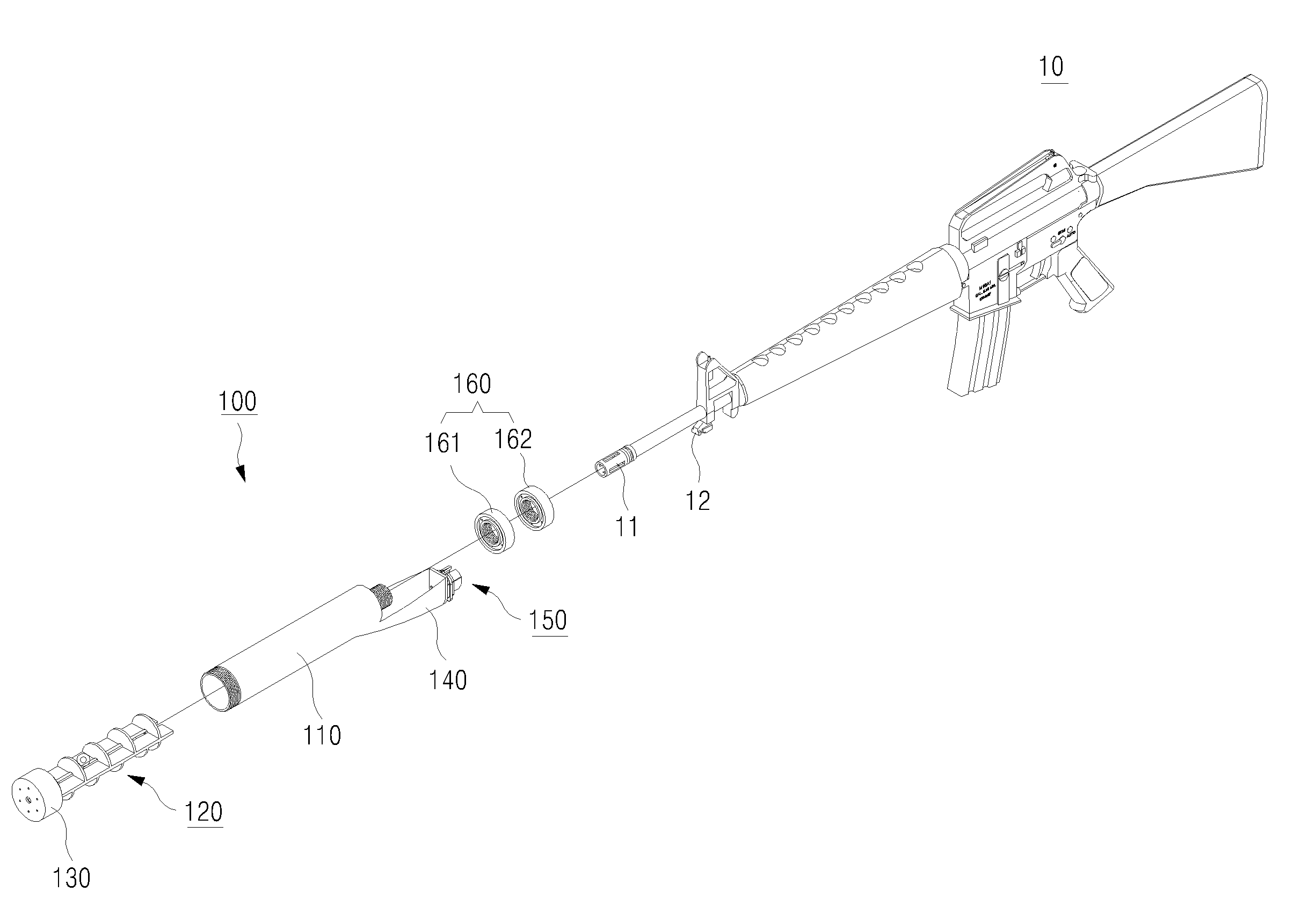
도 1은 본 발명에 따른 원터치 착검방식의 휴대용 소음기가 소총 일측에 분해된 상태를 도시한 사시도이다.
도 2는 본 발명에 따른 원터치 착검방식의 휴대용 소음기가 소총에 장착된 상태를 도시한 사시도이다.
도 3은 본 발명에 따른 원터치 착검방식의 휴대용 소음기의 하우징을 도시한 사시도이다.
도 4는 본 발명에 따른 원터치 착검방식의 휴대용 소음기의 하우징을 도시한 단면도이다.
도 5는 본 발명에 따른 원터치 착검방식의 휴대용 소음기의 흡음부재를 도시한 사시도이다.
도 6은 본 발명에 따른 원터치 착검방식의 휴대용 소음기의 역분사압력 배출부재를 도시한 단면도이다.
도 7은 본 발명에 따른 원터치 착검방식의 휴대용 소음기가 소총에 장착된 상태르 도시한 단면도이다.Figure 1 is a perspective view showing a disassembled state of the one-touch type portable silencer according to the present invention on one side of the rifle.
Figure 2 is a perspective view showing a state in which the portable silencer of the one-touch detection method according to the present invention is mounted on a rifle.
Figure 3 is a perspective view showing the housing of a portable silencer of the one-touch detection method according to the present invention.
Figure 4 is a cross-sectional view showing the housing of a portable silencer of the one-touch detection method according to the present invention.
Figure 5 is a perspective view showing a sound-absorbing member of a portable silencer of the one-touch detection method according to the present invention.
Figure 6 is a cross-sectional view showing the reverse injection pressure discharge member of the one-touch detection type portable silencer according to the present invention.
Figure 7 is a cross-sectional view showing a state in which the portable silencer of the one-touch detection method according to the present invention is mounted on a rifle.
이하에서는, 본 발명에 따른 원터치 착검방식의 휴대용 소음기의 일실시 예를 들어 상세하게 설명한다.Hereinafter, an embodiment of the portable silencer of the one-touch detection method according to the present invention will be described in detail.
우선, 도면들 중, 동일한 구성요소 또는 부품들은 가능한 한 동일한 참조부호를 나타내고 있음에 유의하여야 한다. 본 발명을 설명함에 있어, 관련된 공지기능 혹은 구성에 대한 구체적인 설명은 발명의 요지를 모호하지 않게 하기 위하여 생략한다. First of all, it should be noted that among the drawings, identical components or parts are given the same reference numerals as much as possible. In describing the present invention, detailed descriptions of related well-known functions or configurations are omitted in order to not obscure the gist of the invention.
도시된 바와 같이 본 발명에 따른 원터치 착검방식의 휴대용 소음기(100)는, 소총(10)의 소염기(11)를 내측으로 삽입가능하도록 중공의 관으로 형성되어 구비되는 하우징(110)과, 상기 하우징(110)에 내설되어 사격에 따른 탄두는 안내하면서 소음을 감소가능하게 단일체로 형성되어 구비되는 흡음부재(120)와, 상기 하우징(110)의 일단에 나사방식으로 결합 및 분리가능하게 설치되되, 중앙부에는 탄두가 지나가도록 형성됨과 아울러 사격에 따른 분사압력을 배출시킬 수 있도록 구비되는 덮개부(130)와, 상기 하우징(110)의 타단 하부로부터 일방향 연장되어 사용자가 손으로 파지가능하게 구비되는 파지부(140)와, 상기 파지부(140)의 외측면에 고정 설치되어 소총(10)의 착검부(12)에 원터치방식으로 장,탈착가능하게 구비되는 장착부(150)와, 상기 하우징(110)의 타단에 나사방식으로 결합 및 분해되어 사격에 따른 역분사압력을 배출시킴과 동시에 소음을 감쇄 그리고 진동을 흡수시킬 수 있도록 구비되는 역분사압력 배출부재(160)를 포함하여 구성된다.As shown, the one-touch silencer type
이하에서, 상기한 본 발명에 따른 원터치 착검방식의 휴대용 소음기를 첨부된 도면 도 1 내지 도 7을 참조하여 보다 상세하게 설명하면 다음과 같다.Hereinafter, the portable silencer of the one-touch detection method according to the present invention described above will be described in more detail with reference to the attached drawings FIGS. 1 to 7.
먼저, 상기한 본 발명에 따른 원터치 착검방식의 휴대용 소음기의 하우징(110)은, 소음을 감소시킬 수 있는 단일체의 흡음부재(120)를 일측 내부 삽입시켜 설치할 수 있도록 형성됨과 아울러, 상기 장착부(150)를 통하여 소총(10)의 착검부(12)에 원터치방식으로 장착시 소총(10)의 소염기(11)를 타측 내부로 삽입가능하도록 중공의 관으로 형성되어 구비된다.First, the
즉, 상기한 하우징(110)은 상기 흡음부재(120)를 내측으로 수용할 수 있도록 일면은 개구되고, 타면은 축경부(111)가 형성된 중공의 관으로 형성되며, 일단 외주면에는 상기 덮개부(130)가 나사방식으로 결합 및 분해될 수 있도록 덮개부결합용 나사부(112)가 형성됨과 아울러, 타면에는 사격에 따른 역분사압력을 안내시킬 수 있도록 상기 축경부(111) 주위에 방사방향으로 역분사압력 배출 안내홀(113)이 복수 개 형성되며, 상기 축경부(111)의 외주면에는 상기 역분사압력 배출부재(160)가 나사방식으로 결합 및 분해될 수 있도록 역분사압력 배출부재용 나사부(111a)가 형성되어 구비된다.That is, the
상기와 같이 구성된 하우징(110)으로 인해, 상기 흡음부재(120)의 설치 및 분해를 신속하고 용이하게 할 수 있다.Due to the
상기한 흡음부재(120)는, 상기 하우징(110)에 내설되어 사격에 따른 탄두는 안내하면서 소음을 감소가능하게 단일체로 형성되어 구비된다.The sound-absorbing
즉, 상기한 흡음부재(120)는 각 일면이 서로에 대하여 이격되게 직사각 형상의 판으로 형성되되, 서로 마주보는 각 내측면에는 사격에 따른 탄두가 지나갈 수 있도록 오목한 제1,2안내곡면(121a,122a)이 형성되어 구비되는 제1,2흡음판(121,122)과, 상기 제1,2흡음판(121,122)의 상면에 각 일단이 일정 간격으로 안착 고정되는 것에 의해 상기 제1,2흡음판(121,122)을 서로 연결시키면서, 상기 하우징(110) 내주면 상부와 상기 제1,2흡음판(121,122) 사이에 상부용 흡음챔버(123a)가 일정 간격으로 복수 개 형성되도록 반원판 형상으로 형성되되, 저면 중앙부는 상기 제1,2안내곡면(121a,122a)과 연장 연결되도록 반호형의 상부용 홈(123b)이 각각 형성되어 구비되는 복 수개의 상부용 흡음격판(123)과, 상기 제1,2흡음판(121,122)의 하면에 각 일단이 일정 간격으로 안착되어 용접으로 고정되는 것에 의해 상기 제1,2흡음판(121,122)을 서로 연결시키면서, 상기 하우징(110) 내주면 하부와 상기 제1,2흡음판(121,122) 사이에 하부용 흡음챔버(124a)가 일정 간격으로 복수 개 형성되도록 반원판 형상으로 형성되되, 상면 중앙부는 상기 제1,2안내곡면(121a,122a)과 연장 연결되도록 반호형의 하부용 홈(124b)이 각각 형성되어 구비되는 복 수개의 하부용 흡음격판(124)으로 구성된다.That is, the above-described sound-absorbing
상기한 바와 같이 흡음부재(120)가 단일체로 구성되어 있으므로 인해, 사용 후 사후관리를 용이하고 신속하게 할 수 있을 뿐만 아니라 간단한 구조로 인해 부품을 잃어 버리는 것을 방지할 수 있다.As described above, since the sound-absorbing
상기한 덮개부(130)는 상기 하우징(110)의 일단에 나사방식으로 결합 및 분리가능하게 설치되는 것에 의해 상기 흡음부재(120)가 하우징(110)으로부터 이탈되는 것을 방지하도록 캡 형상으로 형성되되, 전면 중앙부에는 탄두가 지나가도록 형성됨과 아울러 사격에 따른 정분사압력을 배출시킬 수 있도록 구비된다.The
즉, 상기한 덮개부(130)는, 전면이 막음되고 후면은 개구된 캡 형상으로 형성되어 상기 하우징(110)의 일단에 나사방식으로 결합 및 분리되도록 내주면에는 나사부가 형성되고, 전면 중앙부에는 탄두가 지나가도록 탄두진출용 홀(131)이 형성되며, 상기 탄두진출용 홀(131) 주위에 형성되어 사격에 따른 정분사압력을 배출시킬 수 있도록 방사방향으로 복수 개의 정분사압력 배출용 홀(132)이 형성되어 구비된다.That is, the
상기한 파지부(140)는 상기 하우징(110)의 타단 하부로부터 일방향 즉, 후방향으로 연장되어 사용자가 손으로 파지가능하게 구비된다.The
그로 인해, 사격 후 가열된 상기한 하우징(110)에 의해 사용자가 손을 데는 것을 방지할 수 있다.As a result, it is possible to prevent the user's hands from being burned by the
상기한 장착부(150)는, 상기 파지부(140)의 외측면에 고정 설치되어 소총(10)의 착검부(12)에 원터치방식으로 장,탈착가능하게 구비된다.The
즉, 상기한 장착부(150)는 상기 파지부(140)의 외측면에 복수 개의 고정스크류를 매개로 일면이 고정되되, 상면은 소총(10)의 착검부(12)를 수용할 수 있도록 착검부용 수용홈(151a)이 형성되고, 양측면은 상단이 상기 착검부용 수용홈(151a)과 연통된 홈(도면부호 생략)이 형성되어 구비되는 장착부용 고정편(151)과, 상기 장착부용 고정편(151)의 양측면에 형성된 홈에 회동핀(미도시함)을 매개로 각각 회동가능하게 삽입되는 것에 의해 하부는 상기 장착부용 고정편(151)의 하부보다 더 돌출되어 엄지와 검지손가락으로 누름가능하게 설치되어 상기 착검부(12)에 걸림 및 걸림 해제가능하게 구비되는 회동부재(152)와, 상기 회동핀을 중앙부로 관통시켜 상기 홈에 삽입되는 것에 의해 일단은 상기 장착부용 고정편(151)에 걸림되고, 타단은 상기 회동부재(152)에 걸림되어 상기 회동부재(152)의 상부가 항상 착검부용 수용홈(151a)측으로 회동될 수 있도록 구비되는 스프링(미도시함)으로 구성된다.That is, the above-mentioned
상기와 같이 구성된 원터치방식의 장착부(150)로 인해, 휴대용 소음기(100)를 소총(10)의 착검부(12)에 신속하게 장,탈착시킬 수 있다.Due to the one-
상기한 역분사압력 배출부재(160)는, 상기 하우징(110)의 축경부(111)에 오링(미도시함)을 개재시켜 나사방식으로 결합 및 분해되는 것에 의해 일면이 상기 하우징(110)의 타면에 밀착되어 사격에 따른 역분사압력을 배출시킴과 동시에 소음을 감쇄 그리고 진동을 흡수시킬 수 있도록 구비된다.The reverse injection
즉, 상기한 역분사압력 배출부재(160)는, 소정의 두께를 갖는 링 형상으로 형성되되, 내주면에는 상기 하우징(110)의 축경부(111)와 나사방식으로 결합 및 분리가능하도록 제1결합나사부(161a)가 형성되고, 일면과 타면에는 상기 하우징(110)의 역분사압력 배출 안내홀(113)을 통하여 분사되는 역분사압력을 확산시켜 소음을 감쇄 그리고 진동을 흡수시킬 수 있도록 제1전,후면요홈(161b,161c)이 형성되며, 상기 제1전면요홈(161b)의 바닥면에는 역분사압력을 배출시킬 수 있도록 제1역분사압력 배출홀(161d)이 방사방향으로 일정 간격으로 복수 개 형성되어 구비되는 제1역분사압력 배출부재(161)와, 상기 하우징(110)의 축경부(111)와 나사방식으로 결합되는 것에 의해 상기 제1역분사압력 배출부재(161)의 타면에 일면이 밀착되도록 소정의 두께를 갖는 링 형상으로 형성되되, 내주면에는 상기 하우징(110)의 축경부(111)와 나사방식으로 결합 및 분리가능하도록 제2결합나사부(162a)가 형성되고, 일면과 타면에는 상기 제1역분사압력 배출부재(161)의 제1역분사압력 배출홀(161d)을 통하여 분사되는 역분사압력을 확산시켜 소음을 감쇄 그리고 진동을 흡수시킬 수 제2전,후면요홈(162b,162c)이 형성되며, 상기 제2전면요홈(162b)의 바닥면에는 역분사압력을 배출시킬 수 있도록 제2역분사압력 배출홀(162d)이 방사방향으로 일정 간격으로 복수 개 형성되어 구비되는 제2역분사압력 배출부재(162)로 구성된다. That is, the reverse injection
상기와 같이 구성된 역분사압력 배출부재(160)로 인해 사격에 따른 역분사압력을 배출시킴과 동시에 소음을 감쇄 그리고 진동을 흡수시킬 수 있다.Due to the reverse injection
이상의 설명은 본 발명의 기술 사상을 예시적으로 설명한 것에 불과한 것으로서, 본 발명이 속하는 기술 분야에서 통상의 지식을 가진 자라면 본 발명의 본질적인 특성에서 벗어나지 않는 범위에서 다양한 수정 및 변형이 가능할 것이다. 따라서, 본 발명에 개시된 실시예들은 본 발명의 기술 사상을 한정하기 위한 것이 아니라 설명하기 위한 것이고, 이러한 실시예에 의하여 본 발명의 기술 사상의 범위가 한정되는 것은 아니다. 본 발명의 보호 범위는 아래의 청구범위에 의하여 해석되어야 하며, 그와 동등한 범위 내에 있는 모든 기술 사상은 본 발명의 권리범위에 포함되는 것으로 해석되어야 할 것이다.The above description is merely an illustrative explanation of the technical idea of the present invention, and various modifications and variations will be possible to those skilled in the art without departing from the essential characteristics of the present invention. Accordingly, the embodiments disclosed in the present invention are not intended to limit the technical idea of the present invention, but are for illustrative purposes, and the scope of the technical idea of the present invention is not limited by these embodiments. The scope of protection of the present invention should be interpreted in accordance with the claims below, and all technical ideas within the equivalent scope should be construed as being included in the scope of rights of the present invention.
10 ; 소총 11 ; 소염기
12; 착검부
100 ; 원터치 착검방식의 휴대용 소음기 110 ; 하우징
120 ; 흡음부재 130 ; 덮개부
140 ; 파지부 150 ; 장착부
160 ; 역분사압력 배출부재10 ;
12; Attachment part
100 ; One-touch type
120 ; sound-absorbing
140 ;
160 ; Reverse injection pressure discharge member
Claims (6)
소총(10)의 소염기(11)를 내측으로 삽입가능하도록 중공의 관으로 형성되어 구비되는 하우징(110)과;
상기 하우징(110)에 내설되어 사격에 따른 탄두는 안내하면서 소음을 감소가능하게 단일체로 형성되어 구비되는 흡음부재(120)와;
상기 하우징(110)의 일단에 나사방식으로 결합 및 분리가능하게 설치되되, 중앙부에는 탄두가 지나가도록 형성됨과 아울러 사격에 따른 분사압력을 배출시킬 수 있도록 구비되는 덮개부(130)와;
상기 하우징(110)의 타단 하부로부터 일방향 연장되어 사용자가 손으로 파지가능하게 구비되는 파지부(140)와;
상기 파지부(140)의 외측면에 고정 설치되어 소총(10)의 착검부(12)에 원터치방식으로 장,탈착가능하게 구비되는 장착부(150)와;
상기 하우징(110)의 타단에 나사방식으로 결합 및 분해되어 사격에 따른 역분사압력을 배출시킴과 동시에 소음을 감쇄 그리고 진동을 흡수시킬 수 있도록 구비되는 역분사압력 배출부재(160)를 포함하되,
상기 흡음부재(120)는, 각 일면이 서로에 대하여 이격되게 직사각 형상의 판으로 형성되되, 서로 마주보는 각 내측면에는 사격에 따른 탄두가 지나갈 수 있도록 오목한 제1,2안내곡면(121a,122a)이 형성되어 구비되는 제1,2흡음판(121,122)과, 상기 제1,2흡음판(121,122)의 상면에 각 일단이 일정 간격으로 안착 고정되는 것에 의해 상기 제1,2흡음판(121,122)을 서로 연결시키면서, 상기 하우징(110) 내주면 상부와 상기 제1,2흡음판(121,122) 사이에 상부용 흡음챔버(123a)가 일정 간격으로 복수 개 형성되도록 반원판 형상으로 형성되되, 저면 중앙부는 상기 제1,2안내곡면(121a,122a)과 연장 연결되도록 반호형의 상부용 홈(123b)이 각각 형성되어 구비되는 복 수개의 상부용 흡음격판(123)과, 상기 제1,2흡음판(121,122)의 하면에 각 일단이 일정 간격으로 안착되어 고정되는 것에 의해 상기 제1,2흡음판(121,122)을 서로 연결시키면서, 상기 하우징(110) 내주면 하부와 상기 제1,2흡음판(121,122) 사이에 하부용 흡음챔버(124a)가 일정 간격으로 복수 개 형성되도록 반원판 형상으로 형성되되, 상면 중앙부는 상기 제1,2안내곡면(121a,122a)과 연장 연결되도록 반호형의 하부용 홈(124b)이 각각 형성되어 구비되는 복 수개의 하부용 흡음격판(124)으로 구성된 것을 특징으로 하는 원터치 착검방식의 휴대용 소음기.
A portable silencer with a one-touch detection method,
a housing 110 formed of a hollow tube so that the muzzle brake 11 of the rifle 10 can be inserted into the inside;
A sound-absorbing member 120 installed in the housing 110 and formed as a single piece to guide the warhead when fired and reduce noise;
A cover portion 130 is installed on one end of the housing 110 to be attachable and detachable in a screw manner, and is formed in the central portion to allow the warhead to pass through and is provided to discharge the injection pressure resulting from shooting;
a gripping portion 140 extending in one direction from the lower end of the housing 110 so that the user can hold it with his or her hand;
A mounting portion 150 is fixedly installed on the outer surface of the grip portion 140 and can be mounted and detached from the attachment portion 12 of the rifle 10 in a one-touch manner;
It includes a reverse injection pressure discharge member 160 that is screwed and disassembled to the other end of the housing 110 to discharge the reverse injection pressure resulting from shooting, attenuate noise, and absorb vibration,
The sound-absorbing member 120 is formed as a rectangular plate with one side spaced apart from each other, and each inner side facing each other has first and second guide curves 121a and 122a that are concave so that the warhead can pass through when fired. ) is formed and provided with the first and second sound-absorbing plates (121,122), and each end is seated and fixed on the upper surface of the first and second sound-absorbing plates (121,122) at regular intervals to connect the first and second sound-absorbing plates (121,122) to each other. While connected, a plurality of upper sound-absorbing chambers 123a are formed at regular intervals between the upper portion of the inner peripheral surface of the housing 110 and the first and second sound-absorbing plates 121 and 122, and are formed in a semi-disc shape, with the central portion of the bottom being the first sound-absorbing plate 121 and 122. , 2 A plurality of upper sound-absorbing diaphragms (123) each provided with a semi-arc-shaped upper groove (123b) so as to be extended and connected to the guide curved surfaces (121a, 122a), and the first and second sound-absorbing plates (121, 122). While connecting the first and second sound-absorbing plates (121, 122) to each other by seating and fixing one end at regular intervals on the lower surface, sound absorption for the lower portion is provided between the lower inner peripheral surface of the housing 110 and the first and second sound-absorbing plates (121, 122). A plurality of chambers 124a are formed in a semi-disc shape at regular intervals, and a semi-arc-shaped lower groove 124b is formed in the central portion of the upper surface to extend and connect with the first and second guide curves 121a and 122a. A one-touch type portable silencer, characterized in that it consists of a plurality of lower sound-absorbing diaphragms (124) provided.
상기 하우징(110)은, 상기 흡음부재(120)를 내측으로 수용할 수 있도록 일면은 개구되고, 타면은 축경부(111)가 형성된 중공의 관으로 형성되며, 일단 외주면에는 상기 덮개부(130)가 나사방식으로 결합 및 분해될 수 있도록 덮개부결합용 나사부(112)가 형성됨과 아울러, 타면에는 사격에 따른 역분사압력을 안내시킬 수 있도록 상기 축경부(111) 주위에 방사방향으로 역분사압력 배출 안내홀(113)이 복수 개 형성되며, 상기 축경부(111)의 외주면에는 상기 역분사압력 배출부재(160)가 나사방식으로 결합 및 분해될 수 있도록 역분사압력 배출부재용 나사부(111a)가 형성되어 구비된 것을 특징으로 하는 원터치 착검방식의 휴대용 소음기.
According to paragraph 1,
The housing 110 is formed as a hollow tube with one side open to accommodate the sound-absorbing member 120 inside and a reduced diameter portion 111 on the other side, and the cover portion 130 on one outer peripheral surface. A threaded portion 112 for coupling the cover is formed so that it can be combined and disassembled using a screw method, and the reverse injection pressure is discharged in a radial direction around the shaft diameter portion 111 so as to guide the reverse injection pressure according to shooting on the other side. A plurality of guide holes 113 are formed, and a threaded portion 111a for the reverse injection pressure discharge member is provided on the outer peripheral surface of the reduced diameter portion 111 so that the reverse injection pressure discharge member 160 can be coupled and disassembled using a screw method. A portable silencer with a one-touch detection method, characterized in that it is formed and provided.
상기 덮개부(130)는, 전면이 막음되고 후면은 개구된 캡 형상으로 형성되어 상기 하우징(110)의 일단에 나사방식으로 결합 및 분리되도록 내주면에는 나사부가 형성되고, 전면 중앙부에는 탄두가 지나가도록 탄두진출용 홀(131)이 형성되며, 상기 탄두진출용 홀(131) 주위에 형성되어 사격에 따른 정분사압력을 배출시킬 수 있도록 방사방향으로 복수 개의 정분사압력 배출용 홀(132)이 형성되어 구비된 것을 특징으로 하는 원터치 착검방식의 휴대용 소음기.
According to claim 1 or 2,
The cover portion 130 is formed in a cap shape with the front closed and the rear open, and a threaded portion is formed on the inner peripheral surface to be screwed and separated from one end of the housing 110, and the front central portion is formed to allow the warhead to pass through. A warhead advancement hole 131 is formed, and a plurality of constant injection pressure discharge holes 132 are formed around the warhead advancement hole 131 in the radial direction to discharge the constant injection pressure resulting from shooting. A portable silencer with a one-touch detection method, characterized in that it is provided.
소총(10)의 소염기(11)를 내측으로 삽입가능하도록 중공의 관으로 형성되어 구비되는 하우징(110)과;
상기 하우징(110)에 내설되어 사격에 따른 탄두는 안내하면서 소음을 감소가능하게 단일체로 형성되어 구비되는 흡음부재(120)와;
상기 하우징(110)의 일단에 나사방식으로 결합 및 분리가능하게 설치되되, 중앙부에는 탄두가 지나가도록 형성됨과 아울러 사격에 따른 분사압력을 배출시킬 수 있도록 구비되는 덮개부(130)와;
상기 하우징(110)의 타단 하부로부터 일방향 연장되어 사용자가 손으로 파지가능하게 구비되는 파지부(140)와;
상기 파지부(140)의 외측면에 고정 설치되어 소총(10)의 착검부(12)에 원터치방식으로 장,탈착가능하게 구비되는 장착부(150)와;
상기 하우징(110)의 타단에 나사방식으로 결합 및 분해되어 사격에 따른 역분사압력을 배출시킴과 동시에 소음을 감쇄 그리고 진동을 흡수시킬 수 있도록 구비되는 역분사압력 배출부재(160)를 포함하되,
상기 장착부(150)는, 상기 파지부(140)의 외측면에 일면이 고정되되, 상면은 소총(10)의 착검부(12)를 수용할 수 있도록 착검부용 수용홈(151a)이 형성되고, 양측면은 상단이 상기 착검부용 수용홈(151a)과 연통된 홈이 형성되어 구비되는 장착부용 고정편(151)과, 상기 장착부용 고정편(151)의 양측면에 형성된 홈에 회동핀을 매개로 각각 회동가능하게 삽입되는 것에 의해 하부는 상기 장착부용 고정편(151)의 하부보다 더 돌출되어 엄지와 검지손가락으로 누름가능하게 설치되어 상기 착검부(12)에 걸림 및 걸림 해제가능하게 구비되는 회동부재(152)와, 상기 회동핀을 중앙부로 관통시켜 상기 홈에 삽입되는 것에 의해 일단은 상기 장착부용 고정편(151)에 걸림되고, 타단은 상기 회동부재(152)에 걸림되어 상기 회동부재(152)의 상부가 항상 착검부용 수용홈(151a)측으로 회동될 수 있도록 구비되는 스프링으로 구성된 것을 특징으로 하는 원터치 착검방식의 휴대용 소음기.A portable silencer with a one-touch detection method,
a housing 110 formed of a hollow tube so that the muzzle brake 11 of the rifle 10 can be inserted into the inside;
A sound-absorbing member 120 installed in the housing 110 and formed as a single piece to guide the warhead when fired and reduce noise;
A cover portion 130 is installed on one end of the housing 110 to be attachable and detachable in a screw manner, and is formed in the central portion to allow the warhead to pass through and is provided to discharge the injection pressure resulting from shooting;
a gripping portion 140 extending in one direction from the lower end of the housing 110 so that the user can hold it with his or her hand;
A mounting portion 150 is fixedly installed on the outer surface of the grip portion 140 and can be mounted and detached from the attachment portion 12 of the rifle 10 in a one-touch manner;
It includes a reverse injection pressure discharge member 160 that is screwed and disassembled to the other end of the housing 110 to discharge the reverse injection pressure resulting from shooting, attenuate noise, and absorb vibration,
The mounting part 150 has one surface fixed to the outer surface of the gripping part 140, and the upper surface is formed with a receiving groove 151a for the attaching part 151a to accommodate the attaching part 12 of the rifle 10, Both sides are provided with a fixing piece 151 for the mounting part, the upper end of which is provided with a groove communicating with the receiving groove 151a for the wearing part, and a rotating pin is used in the groove formed on both sides of the fixing part 151 for the mounting part. By being rotatably inserted, the lower part protrudes further than the lower part of the mounting part fixing piece 151, so that it can be pressed with the thumb and index finger, and is provided to be able to be caught and released from the attachment part 12. (152) and the pivoting pin is inserted into the groove through the central portion, so that one end is caught by the fixing piece 151 for the mounting part and the other end is caught by the pivoting member 152. ) A portable silencer with a one-touch detection method, characterized in that it is composed of a spring so that the upper part of the detection unit can always be rotated toward the receiving groove (151a) for the detection unit.
상기 역분사압력 배출부재(160)는, 링 형상으로 형성되되, 내주면에는 상기 하우징(110)의 축경부(111)와 나사방식으로 결합 및 분리가능하도록 제1결합나사부(161a)가 형성되고, 일면과 타면에는 상기 하우징(110)의 역분사압력 배출 안내홀(113)을 통하여 분사되는 역분사압력을 확산시켜 소음을 감쇄 그리고 진동을 흡수시킬 수 있도록 제1전,후면요홈(161b,161c)이 형성되며, 상기 제1전면요홈(161b)의 바닥면에는 역분사압력을 배출시킬 수 있도록 제1역분사압력 배출홀(161d)이 방사방향으로 일정 간격으로 복수 개 형성되어 구비되는 제1역분사압력 배출부재(161)와, 상기 하우징(110)의 축경부(111)와 나사방식으로 결합되는 것에 의해 상기 제1역분사압력 배출부재(161)의 타면에 일면이 밀착되도록 소정의 두께를 갖는 링 형상으로 형성되되, 내주면에는 상기 하우징(110)의 축경부(111)와 나사방식으로 결합 및 분리가능하도록 제2결합나사부(162a)가 형성되고, 일면과 타면에는 상기 제1역분사압력 배출부재(161)의 제1역분사압력 배출홀(161d)을 통하여 분사되는 역분사압력을 확산시켜 소음을 감쇄 그리고 진동을 흡수시킬 수 제2전,후면요홈(162b,162c)이 형성되며, 상기 제2전면요홈(162b)의 바닥면에는 역분사압력을 배출시킬 수 있도록 제2역분사압력 배출홀(162d)이 방사방향으로 일정 간격으로 복수 개 형성되어 구비되는 제2역분사압력 배출부재(162)로 구성된 것을 특징으로 하는 원터치 착검방식의 휴대용 소음기.
In paragraph 2
The reverse injection pressure discharge member 160 is formed in a ring shape, and a first coupling screw portion 161a is formed on the inner peripheral surface so that it can be coupled to and separated from the reduced diameter portion 111 of the housing 110 in a screw manner, On one side and the other side, first front and rear grooves (161b, 161c) are provided to spread the reverse injection pressure sprayed through the reverse injection pressure discharge guide hole 113 of the housing 110 to attenuate noise and absorb vibration. is formed, and on the bottom surface of the first front groove (161b), a plurality of first reverse injection pressure discharge holes (161d) are formed at regular intervals in the radial direction to discharge the reverse injection pressure. The injection pressure discharge member 161 is coupled to the reduced diameter portion 111 of the housing 110 in a screw manner to form a predetermined thickness so that one side is in close contact with the other side of the first reverse injection pressure discharge member 161. It is formed in a ring shape, and a second coupling screw portion 162a is formed on the inner peripheral surface so as to be coupled to and separate from the reduced diameter portion 111 of the housing 110 in a screw manner, and the first reverse injection pressure is applied to one side and the other side. Second front and rear grooves 162b and 162c are formed to attenuate noise and absorb vibration by spreading the reverse injection pressure sprayed through the first reverse injection pressure discharge hole 161d of the discharge member 161, A second reverse injection pressure discharge member is provided on the bottom of the second front groove (162b) with a plurality of second reverse injection pressure discharge holes (162d) formed at regular intervals in the radial direction to discharge the reverse injection pressure. (162) A portable silencer with a one-touch detection method, characterized in that it consists of (162).
Priority Applications (1)
| Application Number | Priority Date | Filing Date | Title |
|---|---|---|---|
| KR1020220027997A KR102640407B1 (en) | 2022-03-04 | 2022-03-04 | One-touch knife-mounted portable silencer |
Applications Claiming Priority (1)
| Application Number | Priority Date | Filing Date | Title |
|---|---|---|---|
| KR1020220027997A KR102640407B1 (en) | 2022-03-04 | 2022-03-04 | One-touch knife-mounted portable silencer |
Publications (2)
| Publication Number | Publication Date |
|---|---|
| KR20230130867A KR20230130867A (en) | 2023-09-12 |
| KR102640407B1 true KR102640407B1 (en) | 2024-02-23 |
Family
ID=88019749
Family Applications (1)
| Application Number | Title | Priority Date | Filing Date |
|---|---|---|---|
| KR1020220027997A Active KR102640407B1 (en) | 2022-03-04 | 2022-03-04 | One-touch knife-mounted portable silencer |
Country Status (1)
| Country | Link |
|---|---|
| KR (1) | KR102640407B1 (en) |
Citations (2)
| Publication number | Priority date | Publication date | Assignee | Title |
|---|---|---|---|---|
| KR101882415B1 (en) * | 2017-12-22 | 2018-07-26 | 다산기공 주식회사 | Silencer for firearms capable of discharging gas backwards |
| KR102108186B1 (en) * | 2019-08-20 | 2020-05-07 | 다산기공 주식회사 | Insert for firearm silencers |
Family Cites Families (1)
| Publication number | Priority date | Publication date | Assignee | Title |
|---|---|---|---|---|
| DE19935929C1 (en) * | 1999-07-30 | 2001-02-15 | Heckler & Koch Gmbh | Bracket for attaching a silencer to the barrel of a handgun |
-
2022
- 2022-03-04 KR KR1020220027997A patent/KR102640407B1/en active Active
Patent Citations (2)
| Publication number | Priority date | Publication date | Assignee | Title |
|---|---|---|---|---|
| KR101882415B1 (en) * | 2017-12-22 | 2018-07-26 | 다산기공 주식회사 | Silencer for firearms capable of discharging gas backwards |
| KR102108186B1 (en) * | 2019-08-20 | 2020-05-07 | 다산기공 주식회사 | Insert for firearm silencers |
Also Published As
| Publication number | Publication date |
|---|---|
| KR20230130867A (en) | 2023-09-12 |
Similar Documents
| Publication | Publication Date | Title |
|---|---|---|
| US10648756B2 (en) | Suppressor assembly | |
| US11162753B2 (en) | Suppressor with integral flash hider and reduced gas back flow | |
| EP1255959B1 (en) | Firearm silencer | |
| US5136924A (en) | Silencer for firearms | |
| FI63486C (en) | LJUDDAEMPARE FOER SKJUTVAPEN | |
| CA2443856C (en) | Muzzle brake | |
| US6308609B1 (en) | Suppressor | |
| US10480883B2 (en) | Silencer with improved mount | |
| US20160076844A1 (en) | Brake Mounted Firearm Noise Suppressor | |
| US20210396485A1 (en) | Firearm sound suppressor baffles | |
| US20150285576A1 (en) | Firearm flash suppressor | |
| BR112020012962B1 (en) | Silencer system for a firearm | |
| KR20190043141A (en) | Modular firearm silencer | |
| US12313360B2 (en) | Suppressor for a firearm | |
| KR20190109727A (en) | silencer | |
| US20170299312A1 (en) | Firearm silencer | |
| US9163892B1 (en) | Muzzle break with supersonic nozzle | |
| US4374484A (en) | Compensator for muzzle climb | |
| ES2985947T3 (en) | Muffler | |
| KR102640407B1 (en) | One-touch knife-mounted portable silencer | |
| US20240003646A1 (en) | Modular wipe element for firearm noise suppressor | |
| RU2683215C1 (en) | Sport rifle with sound silencer | |
| US12018904B2 (en) | Modular sound suppressing device for firearms | |
| RU2402736C1 (en) | Set of integrated silencer and plug-recoil reducer-compensator for subsonic and supersonic modes of firing from firearms | |
| EP0151112A1 (en) | Weapon stabilizer and recoil reducer |
Legal Events
| Date | Code | Title | Description |
|---|---|---|---|
| PA0109 | Patent application |
Patent event code: PA01091R01D Comment text: Patent Application Patent event date: 20220304 |
|
| PA0201 | Request for examination | ||
| PG1501 | Laying open of application | ||
| E902 | Notification of reason for refusal | ||
| PE0902 | Notice of grounds for rejection |
Comment text: Notification of reason for refusal Patent event date: 20231224 Patent event code: PE09021S01D |
|
| E701 | Decision to grant or registration of patent right | ||
| PE0701 | Decision of registration |
Patent event code: PE07011S01D Comment text: Decision to Grant Registration Patent event date: 20240214 |
|
| GRNT | Written decision to grant | ||
| PR0701 | Registration of establishment |
Comment text: Registration of Establishment Patent event date: 20240220 Patent event code: PR07011E01D |
|
| PR1002 | Payment of registration fee |
Payment date: 20240220 End annual number: 3 Start annual number: 1 |
|
| PG1601 | Publication of registration |