KR102555552B1 - Multipurpose prefab fence - Google Patents
Multipurpose prefab fence Download PDFInfo
- Publication number
- KR102555552B1 KR102555552B1 KR1020200173371A KR20200173371A KR102555552B1 KR 102555552 B1 KR102555552 B1 KR 102555552B1 KR 1020200173371 A KR1020200173371 A KR 1020200173371A KR 20200173371 A KR20200173371 A KR 20200173371A KR 102555552 B1 KR102555552 B1 KR 102555552B1
- Authority
- KR
- South Korea
- Prior art keywords
- clip
- prefabricated fence
- wall
- walls
- fence
- Prior art date
- Legal status (The legal status is an assumption and is not a legal conclusion. Google has not performed a legal analysis and makes no representation as to the accuracy of the status listed.)
- Active
Links
Images


Classifications
-
- A—HUMAN NECESSITIES
- A01—AGRICULTURE; FORESTRY; ANIMAL HUSBANDRY; HUNTING; TRAPPING; FISHING
- A01K—ANIMAL HUSBANDRY; AVICULTURE; APICULTURE; PISCICULTURE; FISHING; REARING OR BREEDING ANIMALS, NOT OTHERWISE PROVIDED FOR; NEW BREEDS OF ANIMALS
- A01K3/00—Pasturing equipment, e.g. tethering devices; Grids for preventing cattle from straying; Electrified wire fencing
- A01K3/002—Grids for preventing cattle from straying through an open passage of an enclosure
-
- A—HUMAN NECESSITIES
- A01—AGRICULTURE; FORESTRY; ANIMAL HUSBANDRY; HUNTING; TRAPPING; FISHING
- A01K—ANIMAL HUSBANDRY; AVICULTURE; APICULTURE; PISCICULTURE; FISHING; REARING OR BREEDING ANIMALS, NOT OTHERWISE PROVIDED FOR; NEW BREEDS OF ANIMALS
- A01K1/00—Housing animals; Equipment therefor
- A01K1/02—Pigsties; Dog-kennels; Rabbit-hutches or the like
- A01K1/03—Housing for domestic or laboratory animals
-
- E—FIXED CONSTRUCTIONS
- E04—BUILDING
- E04H—BUILDINGS OR LIKE STRUCTURES FOR PARTICULAR PURPOSES; SWIMMING OR SPLASH BATHS OR POOLS; MASTS; FENCING; TENTS OR CANOPIES, IN GENERAL
- E04H17/00—Fencing, e.g. fences, enclosures, corrals
- E04H17/14—Fences constructed of rigid elements, e.g. with additional wire fillings or with posts
- E04H17/16—Fences constructed of rigid elements, e.g. with additional wire fillings or with posts using prefabricated panel-like elements, e.g. wired frames
Landscapes
- Life Sciences & Earth Sciences (AREA)
- Environmental Sciences (AREA)
- Animal Husbandry (AREA)
- Biodiversity & Conservation Biology (AREA)
- Engineering & Computer Science (AREA)
- Zoology (AREA)
- Architecture (AREA)
- Animal Behavior & Ethology (AREA)
- Clinical Laboratory Science (AREA)
- General Health & Medical Sciences (AREA)
- Health & Medical Sciences (AREA)
- Civil Engineering (AREA)
- Structural Engineering (AREA)
- Housing For Livestock And Birds (AREA)
- Fencing (AREA)
Abstract
본 발명의 다목적 조립식 울타리는 바닥면으로부터 소정의 높이로 직립 형성되고 내부에 소정의 공간을 갖으며, 판형상의 부재이며, 상하 길이 방향으로 형성된 홈 형상의 슬릿(10a)을 포함하는 복수의 벽체(10); 및 상기 일측이 벽체(10)의 측면에 끼워지며, 타측이 이웃하는 다른 벽체(10)에 끼워짐으로써 서로 이웃하는 2개의 벽체(10)를 고정 연결하는 클립(20); 을 포함하는 것을 특징으로 한다.The multi-purpose prefabricated fence of the present invention is formed upright at a predetermined height from the floor, has a predetermined space therein, is a plate-shaped member, and includes a plurality of walls including groove-shaped slits 10a formed in the vertical direction ( 10); and a clip 20 having one side fitted to the side of the wall 10 and the other side fitted to another adjacent wall 10 to fixally connect the two adjacent walls 10 to each other; It is characterized in that it includes.
Description
본 발명은 다목적 조립식 울타리에 관한 것으로, 더욱 상세하게는 일반 가정이나 그 밖의 공간에 설치하여 유아나 애완동물이 소정의 놀이 공간 내에서 안정하게 활동함과 동시에 소정의 영역 외부로 이탈하는 것을 막아줄 수 있도록 구성된 다목적 조립식 울타리에 관한 것이다.The present invention relates to a multipurpose prefabricated fence, and more particularly, to be installed in a general home or other space to prevent infants or pets from escaping outside a predetermined area while stably operating in a predetermined play space. It relates to a multi-purpose prefabricated fence configured to be able to
일반적으로 애완동물을 키우는 가정이나 애완동물 병원, 혹은 집에 유아 또는 어린이가 있는 경우에는 유아, 어린이, 애완동물을 보호하기 위한 펜스, 울타리 등이 설치되고, 생활공간을 넓히기 위하여 여러 개의 금속재 판을 겹쳐서 조립하는 경우가 대부분이다.In general, in homes where pets are raised, in pet hospitals, or when there are infants or children at home, fences and fences are installed to protect infants, children, and pets, and several metal plates are installed to expand living space. In most cases, they are overlapped.
종래기술로 실용신안등록 제20-0334577호 『애완동물용 조립식 울타리』가 있는데, 상기 종래기술은 상부면에 2개의 체결구가 형성된 다수개의 지지블록, 중앙부가 절곡되어 양측으로 대칭 형성된 다수개의 선재기둥 및 양측에 2개의 수직 연결홈이 평행하게 형성된 다수개의 연결블록을 포함하여 구성되되, 상기 지지블록의 체결구에 선재기둥의 양단이 수직하게 삽입 고정되고, 상기 연결블록 각각의 수직 연결홈에 서로 다른 선재기둥의 일측이 삽입 연결되는 구성이 연속적으로 이루고 있어, 조립되는 지지블록, 선재기둥 및 연결블록의 수를 증감시킴으로써 사용자의 필요에 따라 울타리의 넓이와 외곽형상을 자유롭게 조절할 수 있어 가정 또는 가축병원 등 다양한 용도로 사용 가능할 뿐만 아니라 형상유지선재를 연결블록에 결합시킴으로써 애완 동물이 울타리를 밀더라도 울타리의 외곽 형상을 견고하게 유지할 수 있다. 또한 울타리 전체의 상부와 하부는 개방되어 있으므로 지면에 애완동물의 배설물을 처리할 수 있는 깔개 상부에 울타리를 설치함으로써 애완동물의 배설물 처리를 용이하게 수행할 수 있고 지지블록, 선재기둥 및 연결블록의 도색을 통하여 미관을 수려하게 장식할 수 있으며, 무엇보다도 애완동물의 스트레스를 최소화하면서도 안전을 유지할 수 있는 장점이 있는 기술을 제시하고 있다.As a prior art, there is Utility Model Registration No. 20-0334577 『Prefabricated Fence for Pets』. It is composed of a column and a plurality of connection blocks formed in parallel with two vertical connection grooves on both sides, wherein both ends of the wire rod column are vertically inserted and fixed into the fasteners of the support block, and in the vertical connection grooves of each of the connection blocks. Since one side of different wire poles is continuously inserted and connected, the width and outline of the fence can be freely adjusted according to the user's needs by increasing or decreasing the number of support blocks, wire poles, and connection blocks to be assembled. Not only can it be used for various purposes such as animal hospitals, but it can also firmly maintain the outer shape of the fence even if the pet pushes the fence by combining the shape-retaining wire with the connection block. In addition, since the upper and lower parts of the entire fence are open, it is possible to easily dispose of pet excrement by installing the fence on the upper part of the rug that can treat pet excrement on the ground, and the support block, wire rod column and connection block Through painting, it is possible to decorate the aesthetics beautifully, and above all, it presents a technology that has the advantage of maintaining safety while minimizing the stress of the pet.
그러나 상기 종래기술은 애완동물용 울타리를 사용자의 필요에 따라 넓이와 외곽형상을 자유롭게 조절할 수 있지만 그 결합과정이 복잡하고 한번 결착된 울타리를 다른 형태로 결착하려면 많은 시간이 걸린다는 문제점이 있고, 울타리의 형상에 따라 한번 제작되면 출입구를 다시 설치하기 어렵고, 겨울철 차가운 통풍을 막거나 다른 동물과의 싸움과 대비하여 외곽과 차단할 수 있는 연결부재가 없어 울타리의 쓰임새가 한정적인 문제점이 있다.However, the prior art can freely adjust the width and outline shape of the pet fence according to the user's needs, but the coupling process is complicated and it takes a lot of time to bind the fence once bound in a different form. Once manufactured according to the shape of the fence, it is difficult to re-install the entrance, and there is a problem in that the use of the fence is limited because there is no connection member that can prevent cold ventilation in winter or block the outside in preparation for fighting with other animals.
나아가 종래기술로 등록실용신안 제20-0357802호 『신축 가능한 애완동물용 철장』이 있는데, 상기 종래기술은 애완동물용 철장의 좌ㅇ우 양 측면 즉, 기본프레임 및 상부철장부에 신축 가능한 구성을 구비하여 애완동물의 크기에 따라 철장의 신축이 가능하도록 한 구성에 그 특징이 있으며, 또한 철장의 신축에 따라 애완동물의 배설물을 받는 배설물 받침대도 신축이 가능하도록 한 구성을 제공하여 애완동물의 크기에 따라 철장이나 받침대를 별도로 구입할 필요가 없기 때문에 불필요한 철장 및 받침대 구입비용이 없고, 보관공간도 효율적으로 활용할 수 있는 기술을 제시하고 있다.Furthermore, as a prior art, there is Registered Utility Model No. 20-0357802 『Stretchable Iron Cage for Pets』. It is characterized by a configuration in which the cage can be stretched according to the size of the pet, and also provides a configuration in which the excrement holder that receives the pet's excrement can be expanded according to the expansion and contraction of the cage. Since there is no need to separately purchase a steel cage or pedestal, there is no need to purchase unnecessary iron cages and pedestals, and a technology that can efficiently utilize storage space is presented.
그러나 상기 종래기술은 고정된 형태의 철장과 배설물 받침대의 길이만을 조절하여 그 공간의 한정되어 한 마리의 애견을 키울 수밖에 없고, 여러 마리의 애견을 키우더라도 독립된 공간이 없어 싸우거나 아픈 애견을 따로 돌봐야 하는 철장을 새로 설치해야 해서 한정된 공간에서 무한정 애견의 울타리나 철장을 늘릴 수 없는 문제점이 있다.However, the prior art only adjusts the length of the fixed iron cage and the excrement stand, so the space is limited and there is no choice but to raise one dog, and even if multiple dogs are raised, there is no independent space, so you have to fight or take care of sick dogs separately. There is a problem in that it is not possible to increase the dog's fence or cage indefinitely in a limited space because a new iron cage must be installed.
아울러 종래기술로 등록실용신안 제20-0424921호 『애완동물용 하우스』가 있는데, 상기 종래기술은 특히 출입문 및 다수의 통풍구를 가지고 결합클립에 의해 분리가능하게 일체로 결합되어 하우스 형상을 갖도록 형성된 골격프레임과, 상기 출입문을 제외한 골격 프레임을 덮으면서 분리가능하게 결합되는 커버의 구성으로 이루어진다. 이에 따라, 분리 및 조립이 간편하여 작은 부피로 운반, 보관할 수 있으며 외부 커버를 손쉽게 분리하여 애완동물용 하우스의 내부 청결상태를 유지할 수 있도록 하여, 분리가능하게 일체로 결합되는 골격프레임과 상기 골격프레임을 덮으면서 분리가능하게 결합되는 커버에 의해 운반 및 보관이 편리하고 보온효과를 가지며 청결상태를 유지할 수 있는 애완동물용 하우스를 제시하고 있다.In addition, as a prior art, there is a registered utility model No. 20-0424921 『pet house』. It consists of a frame and a cover that is detachably coupled while covering the skeleton frame except for the door. Accordingly, it is easy to separate and assemble, so that it can be transported and stored in a small volume, and the outer cover can be easily removed to maintain the internal cleanliness of the pet house. A house for pets that is convenient to carry and store by a cover that is detachably coupled while covering, has a warming effect, and can maintain a clean state.
그러나 상기 종래기술은 출입문을 제외한 골격 프레임을 덮으면서 결합되는 커버에 의하여 출입문과 골격을 따로 결합하여야 하고, 하부, 상하, 좌우측을 하나씩 결합하여 하나의 공간만 형성이 되어 여러 마리의 애견을 각각 독립된 공간에 생활할 수 있도록 제공하지 못하는 문제점이 있다.However, in the prior art, the door and the skeleton must be separately combined by a cover that is combined while covering the skeleton frame except for the door, and only one space is formed by combining the bottom, top, bottom, left and right sides one by one, so that several dogs can be independently There is a problem that cannot be provided to live in space.
본 발명은 기존의 유아 내지 애완동물용 울타리의 문제를 해결하기 위해 안출한 것으로 간단하게 조립 및 해체를 하고, 이동이 용이하면서도 심미감을 줄 수 있는 다목적 조립식 울타리를 제공함을 목적으로 한다.An object of the present invention is to provide a multi-purpose prefabricated fence that can be easily assembled and disassembled to solve the problems of existing fences for infants and pets, and can be easily moved and given a sense of aesthetics.
또한 다양한 형태의 면적과 높이를 가지는 다목적 조립식 울타리를 제공함을 목적으로 한다.It is also an object of the present invention to provide multi-purpose prefabricated fences having various types of areas and heights.
본 발명의 다목적 조립식 울타리는 바닥면으로부터 소정의 높이로 직립형성되고 내부에 소정의 공간을 갖는다.The multipurpose prefabricated fence of the present invention is formed upright at a predetermined height from the floor surface and has a predetermined space therein.
본 발명의 다목적 조립식 울타리는 판형상의 부재이며, 상하 길이 방향으로 형성된 홈형상의 슬릿(10a)을 포함하는 복수의 벽체(10); 및 상기 일측이 벽체(10)의 측면에 끼워지며, 타측이 이웃하는 다른 벽체(10)에 끼워짐으로써 서로 이웃하는 2개의 벽체(10)를 고정 연결하는 클립(20);을 포함할 수 있다.The multi-purpose prefabricated fence of the present invention is a plate-shaped member, and includes a plurality of
상기 클립은 일정한 폭을 갖는 띠 형상인 2개의 외부판(21); 상기 2개의 외부판 사이에 위치하며, 상기 2개의 외부판을 연결하는 내부연결부(22); 및 상기 슬릿(10a)에 끼워지는 결합돌기(23);를 포함할 수 있다.The clip has two
상기 결합돌기(23)는 2개의 외부판(21)에 의해 형성되는 내부 공간에 위치하되, 상기 2개의 외부판(21) 사이에서 적어도 어느 하나의 외부판(21)에 위치할 수 있다.The
상기 결합돌기(23)는 상기 외부판(21)의 길이 방향을 따라 길이 방향으로 형성될 수 있다.The
상기 다목적 조립식 울타리는 상기 클립(20)의 하부에 연결되는 하부 받침(30)을 더 포함할 수 있다.The multi-purpose prefabricated fence may further include a
상기 하부 받침(30)은 상기 내부연결부(22)에 연결되고 나사산이 형성될 돌출부(31); 및 상기 돌출부(31)의 일단에 형성된 받침부(32);를 포함할 수 있다.The
상기 내부연결부(22)는 상하 방향으로 형성된 중공부(22a)를 더 포함할 수 있다.The
상기 돌출부(31)의 타단이 상기 중공부(22a)에 나사 결합되될 수 있따.The other end of the
상기 클립(20)은 중심부가 90도 또는 120도로 꺽인 코너 클립(201); 및 중심부가 180도인 중앙 클립(202);을 포함할 수 있다.The
상기 다목적 조립식 울타리는 12개의 벽체(10)에 의해 6개의 벽면이 형성될 수 있다.In the multi-purpose prefabricated fence, 6 walls may be formed by 12
서로 이웃하는 벽면은 상기 코너 클립(201)으로 연결되고, 하나의 벽면 내에서 서로 이웃하는 벽체(10)는 상기 중앙 클립(202)으로 연결될 수 있다.Walls adjacent to each other may be connected by the
본 발명의 다목적 조립식 울타리는 상기 벽체(10)에 의해 형성된 공간 내부에 설치되며, 육각형 형상의 판형 부재인 바닥판(40)을 더 포함할 수 있다.The multi-purpose prefabricated fence of the present invention is installed inside the space formed by the
본 발명의 다목적 조립식 울타리는 간단하게 조립 및 해체를 하고, 이동이 용이하면서도 심미감을 줄 수 있다.The multipurpose prefabricated fence of the present invention can be simply assembled and dismantled, and can be easily moved and aesthetically pleasing.
또한 다양한 형태의 면적과 높이를 가지는 다목적 조립식 울타리를 제공할 수 있다.In addition, it is possible to provide multi-purpose prefabricated fences having various shapes and heights.
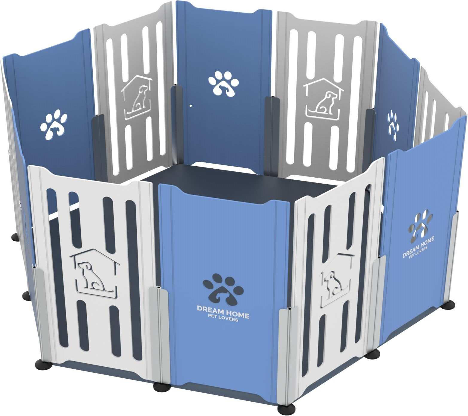
도 1은 본 발명의 제1 실시예에 따른 다목적 조립식 울타리의 사시도이다.
도 2는 본 발명의 제1 실시예에 따른 다목적 조립식 울타리의 클립의 상부을 나타내는 도면이다.
도 3은 본 발명의 제1 실시예에 따른 다목적 조립식 울타리의 클립의 하부을 나타내는 도면이다.
도 4는 본 발명의 제1 실시예에 따른 다목적 조립식 울타리의 사용 상태를 나타내는 도면이다.
도 5는 본 발명의 제2 실시예에 따른 다목적 조립식 울타리의 사시도이다.
도 6은 본 발명의 제2 실시예에 따른 다목적 조립식 울타리의 사용 상태를 나타내는 도면이다.1 is a perspective view of a multipurpose prefabricated fence according to a first embodiment of the present invention.
Figure 2 is a view showing the top of the clip of the multi-purpose prefabricated fence according to the first embodiment of the present invention.
Figure 3 is a view showing the lower part of the clip of the multipurpose prefabricated fence according to the first embodiment of the present invention.
Figure 4 is a view showing the state of use of the multi-purpose prefabricated fence according to the first embodiment of the present invention.
5 is a perspective view of a multipurpose prefabricated fence according to a second embodiment of the present invention.
6 is a view showing a state of use of a multi-purpose prefabricated fence according to a second embodiment of the present invention.
하기의 설명에서는 본 발명의 실시예에 따른 동작을 이해하는데 필요한 부분만이 설명되며, 그 이외 부분의 설명은 본 발명의 요지를 흩트리지 않도록 생략될 것이라는 것을 유의하여야 한다.It should be noted that in the following description, only parts necessary for understanding the operation according to the embodiment of the present invention are described, and descriptions of other parts will be omitted so as not to distract from the subject matter of the present invention.
또한 이하에서 설명되는 본 명세서 및 청구범위에 사용된 용어나 단어는 통상적이거나 사전적인 의미로 한정해서 해석되어서는 아니 되며, 발명자는 그 자신의 발명을 가장 최선의 방법으로 설명하기 위해 용어의 개념으로 적절하게 정의할 수 있다는 원칙에 입각하여 본 발명의 기술적 사상에 부합하는 의미와 개념으로 해석되어야만 한다. 따라서 본 명세서에 기재된 실시예와 도면에 도시된 구성은 본 발명의 바람직한 하나의 실시예에 불과할 뿐이고, 본 발명의 기술적 사상을 모두 대변하는 것은 아니므로, 본 출원시점에 있어서 이들을 대체할 수 있는 다양한 균등물과 변형예들이 있을 수 있음을 이해하여야 한다.In addition, the terms or words used in this specification and claims described below should not be construed as being limited to the usual or dictionary meaning, and the inventors use the concept of terms to describe their invention in the best way. Based on the principle that it can be properly defined, it should be interpreted as meaning and concept consistent with the technical spirit of the present invention. Therefore, the embodiments described in this specification and the configurations shown in the drawings are only one preferred embodiment of the present invention, and do not represent all of the technical spirit of the present invention, so that various alternatives can be used at the time of this application. It should be understood that there may be equivalents and variations.
이하에서 사용될 수 있는 “포함한다, ”가진다“, ”구성된다“ 등의 표현은 추가적인 구성 요소나 기능을 배제하지는 않는 것으로 이해되어야 한다.It should be understood that expressions such as “comprises,” “has,” and “consists of” that may be used below do not exclude additional components or functions.
이하에서 사용될 수 있는 ”결합된다“, ”연결된다“등의 표현은 명시적으로 언급되지 않는한 직접적으로 겹합되거나 연결되어 있는 경우뿐만 아니라 중간에 다른 구성 요소가 존재하거나 개재될 수도 있는 것으로 이해되어야 한다.Expressions such as “combined” and “connected” that can be used below should be understood as not only being directly combined or connected, but also that other components may exist or be intervened in the middle unless explicitly stated. do.
이하에서 용어의 사용에 있어서 다수의 표현은 명시적으로 언급되지 않는 한 복수의 표현을 배제하지 않는 것으로 이해되어야 한다.In the following use of the term, plural expressions should be understood as not excluding plural expressions unless explicitly stated otherwise.
다목적 조립식 울타리는 바닥면으로부터 소정의 높이로 직립형태로 형성되고 내부에 소정의 공간을 갖는다. 내부 공간에서 애완동물이나 유아가 활동할 수 있는 공간이 형성된다.The multi-purpose prefabricated fence is formed in an upright form at a predetermined height from the floor and has a predetermined space therein. In the interior space, a space for pets or infants to be active is formed.
이하 본 발명의 제1 실시예에 따른 다목적 조립식 울타리에 대하여 상세하게 설명한다.Hereinafter, a multi-purpose prefabricated fence according to a first embodiment of the present invention will be described in detail.
도 1은 본 발명의 제1 실시예에 따른 다목적 조립식 울타리의 사시도이다. 도 2는 본 발명의 제1 실시예에 따른 다목적 조립식 울타리의 클립의 상부을 나타내는 도면이다. 도 3은 본 발명의 제1 실시예에 따른 다목적 조립식 울타리의 클립의 하부을 나타내는 도면이다. 도 4는 본 발명의 제1 실시예에 따른 다목적 조립식 울타리의 사용 상태를 나타내는 도면이다.1 is a perspective view of a multipurpose prefabricated fence according to a first embodiment of the present invention. Figure 2 is a view showing the top of the clip of the multi-purpose prefabricated fence according to the first embodiment of the present invention. Figure 3 is a view showing the lower part of the clip of the multipurpose prefabricated fence according to the first embodiment of the present invention. Figure 4 is a view showing the state of use of the multi-purpose prefabricated fence according to the first embodiment of the present invention.
복수의 벽체(10), 클립(20), 하부 받침(30) 및 바닥판(40)을 포함한다.It includes a plurality of
벽체(10)는 판형상의 부재이며, 대략 직사각형의 외형을 갖는다. 벽체(10)는 나무 또는 내부가 비어있는 플라스틱 재질로 제작될 수 있다.The
벽체(10)는 상하 길이 방향으로 형성된 홈 형상의 슬릿(10a)을 포함한다. 슬릿(10a)은 벽체(10)의 양면에 형성될 수 있다. 2개의 슬릿(10a)이 벽체의 앞면과 뒷면에서 서로 대응하는 위치에 형성될 수 있다.The
벽체(10)의 한면에 슬릿(10a)이 2개 형성될 수 있다. 슬릿(10a)은 벽체(10)의 측면에 근접한 위치에 위치할 수 있다. 한면에 2개 형성되고, 다른 면에 2개가 형성되므로, 하나의 벽체(10)에는 4개의 슬릿(10a)이 형성될 수 있다.Two
도 1에 도시된 바와 같이, 벽체(10)에는 양면을 관통하는 다양한 패턴의 구멍을 형성할 수 있다. 유아용 울타리인 경우에는 유아가 좋아하는 패턴의 구멍을 형성할 수 있고, 애완 동물인 경우에는 애완 동물과 관련된 패턴의 구멍을 형성할 수 있다. 이러한 패턴을 통해 사용자에게 심미감을 줄 수 있다.As shown in FIG. 1 , various patterns of holes penetrating both sides of the
클립(20)은 서로 이웃하는 2개의 벽체(10)를 고정 연결한다. 클립(20)은 알루미늄과 같은 금속 재질, 탄성을 갖는 플라스틱일 수 있다. 또한 클립(20)은 탄성을 갖는 투명 플라스틱일 수 있다.The
클립(20)의 일측이 벽체(10)의 측면에 끼워지며, 타측이 이웃하는 다른 벽체(10)에 끼워짐으로써 서로 이웃하는 2개의 벽체(10)를 고정 연결할 수 있다.One side of the
클립(20)은 단면이 대락 ‘H’형상이며 길이 방향으로 연장된 형상을 갖는다. 클립(20)은 2개의 외부판(21), 2개의 외부판(21)을 연결하는 내부 연결부(22) 및 결합돌기(23)를 포함한다.The
외부판(21)은 일정한 폭을 갖는 띠 형상이며, 2개의 외부판(21)이 일정거리 이격되어 위치한다. The
내부연결부(22)는 2개의 외부판(21) 사이에 위치하며, 2개의 외부판(21)을 연결한다. 내부연결부(22)도 외부판(21)과 같이 길이 방향으로 연장된 형상이며, 내부연결부(22)의 폭에 의해 2개의 외부판(21)의 이격 거리가 결정된다.The
내부연결부(22)는 상하 방향으로 형성된 중공부(22a)를 포함할 수 있다.The
결합돌기(23)는 벽체(10)에 형성된 슬릿(10a)에 끼워진다.The
결합돌기(23)는 2개의 외부판(21)에 의해 형성되는 내부 공간에 위치하며, 2개의 외부판(21) 사이에서 적어도 어느 하나의 외부판(21)에 위치할 수 있다.The
결합돌기(23)는 외부판(21)의 길이 방향을 따라 길이 방향으로 형성될 수 있다.The
서로 이웃하는 2개의 벽체(10)를 수직으로 세우고 2개의 벽체(10)의 측면이 서로 근접하도록 위치한 상태에서, 클립(20)의 결합돌기(23)를 벽체(10)의 슬릿(10a)에 위치시킨다. 클립(20)의 윗부분에 힘을 가하여 누르면, 결합돌기(23)가 슬릿(10a)에 끼워진 상태로 하강하게 된다. 클립(20)이 하강하면서, 2개의 이웃하는 벽체(10)를 고정 연결한다.In a state where the two
클립(20)을 벽체(10)의 측면에서 강제로 끼우는 것도 가능하다. 즉, 클립(20)을 벽체(10)의 측면에 위치시킨 상태에서 2개의 외부판(21) 사이에 벽체(10)의 측면을 끼워 넣는다. 2개의 외부판(21)이 벌어지면서, 벽체(10)의 측면이 삽입된다. 결국 결합돌기(23)가 슬릿(10a)에 끼워짐으로써 클립(20)과 벽체(10)가 고정 연결된다. 한 쪽 벽체(10)를 클립(20)에 연결하고, 다른 쪽 벽체(10)를 클립(20)에 끼워서 연결하면, 하나의 클립(20)으로 서로 이웃하는 2개의 벽체(10)를 고정 연결할 수 있다.It is also possible to forcibly insert the
클립(20)은 중심부가 120도로 꺽인 코너 클립(201)과 중심부가 180도인 중앙 클립(202)일 수 있다.The
다목적 조립식 울타리는 12개의 벽체(10)에 의해 6개의 벽면이 형성될 수 있다.Multi-purpose prefabricated fence can be formed by 6 walls by 12 walls (10).
서로 이웃하는 2개의 벽체(10)를 중앙 클립(202)으로 연결하면 하나의 벽면이 형성된다.When two
서로 이웃하는 벽면은 코너 클립(201)으로 연결할 수 있다. 코너 클립(201)을 이용하면 2개의 벽면을 120도로 설치할 수 있다.Walls adjacent to each other can be connected with corner clips (201). Using the
즉, 코너 클립(201)은 벽체(10)를 120도로 연결할 수 있고, 중앙 클립은 벽체(10)를 180도로 연결할 수 있다.That is, the
도 1에는 다목적 조립식 울타리가 육각 기둥 형상인 것이 도시되어 있으나, 벽체(10)의 위치를 배열에 따라, 직육면체 내지 정육면체 구조로도 설치할 수 있다.Although the multi-purpose prefabricated fence is shown in the shape of a hexagonal column in FIG. 1, it may be installed in a cuboid or regular hexahedron structure according to the arrangement of the
특히 코너 클립(201)을 120도가 아닌 90도로 꺾이도록 제작할 수 있으며, 90도로 꺾인 코너 클립을 이용하면, 서로 이웃하는 벽체(10)가 서로 90도가 되도록 설치할 수 있다.In particular, the
도 1에서는 코너 클립(201)과 중앙 클립(202)이 벽체(10) 사이에 위치하고, 벽체(10)의 하단부에 근접하도록 설치되어 있다. 클립(20)을 벽체(10) 위쪽으로 돌출되도록 설치하면, 클립(20)에 2개의 벽체(10)를 더 설치할 수 있다. 즉, 하나의 클립(20)으로 4개의 벽체(10)를 연결할 수 있다.In FIG. 1 , a
클립(20)은 옆으로 이웃하는 벽체(10)를 연결할 수 있을 뿐만 아니라, 상하로 이웃하는 위치하는 벽체(10)를 연결할 수 있다. 따라서, 벽체(10)와 클립(20)으로 원하는 면적의 울타리로 조립할 수 있을 뿐만 아니라, 상하로 연장된 울타리로 조립할 수도 있다.The
하부 받침(30)은 클립(20)의 하부에 연결되어, 다목적 조립식 울타리를 지지한다.The
하부 받침(30)은 돌출부(31) 및 받침부(32)를 포함한다. The
돌출부(31)는 클립(20)의 내부연결부(22)에 연결된다. 돌출부(31)는 나사산이 형성된 봉 형상이다. 돌출부(31)는 내부연결부(22)의 상하 방향으로 형성된 중공부(22a)에 삽입되어 연결될 수 있으며, 나사산이 있으므로 돌출부(31)의 회전 정도에 따라 돌출부(31)가 중공부(22a)에 삽입되는 깊이를 조절할 수 있다. 즉 하부 받침(30)을 이용하여 지면으로부터 클립(20)이 이격된 높이를 조절할 수 있다.The protruding
돌출부(31)의 일단에는 받침부(32)가 위치한다. 받침부(32)는 바닥면에 접하며 다목적 조립식 울타리를 지지한다.At one end of the protruding
바닥판(40)은 다목적 조립식 울타리 내부 바닥에 설치된다. 즉, 벽체(10)에 의해 형성된 공간 내부에 설치된다.The
도 1에 도시된 바와 같이 바닥판(40)은 육각형 형상의 판형 부재일 수 있다. 물론 벽체(10)가 직육면체 내지 정육면체 구조로도 설치되는 경우에는 그 배치에 맞는 바닥판(40)을 제작할 수 있다.As shown in FIG. 1 , the
이하에서는 본 발명의 제2 실시예에 따른 다목적 조립식 울타리에 대하여 설명한다.Hereinafter, a multi-purpose prefabricated fence according to a second embodiment of the present invention will be described.
도 5는 본 발명의 제2 실시예에 따른 다목적 조립식 울타리의 사시도이다. 도 6은 본 발명의 제2 실시예에 따른 다목적 조립식 울타리의 사용 상태를 나타내는 도면이다.5 is a perspective view of a multipurpose prefabricated fence according to a second embodiment of the present invention. 6 is a view showing a state of use of a multi-purpose prefabricated fence according to a second embodiment of the present invention.
제1 실시예에 따른 다목적 조립식 울타리와 마찬가지로 제2 실시예에 따른 다목적 조립식 울타리도 복수의 벽체(10), 클립(20) 및 바닥판(40)을 포함할 수 있다.Like the multi-purpose prefabricated fence according to the first embodiment, the multi-purpose prefabricated fence according to the second embodiment may also include a plurality of
벽체(10)와 바닥판(40)은 제1 실시예에 따른 다목적 조립식 울타리와 동일하므로 상세한 설명은 생략한다.Since the
제1 실시예에 따른 다목적 조립식 울타리와는 달리 제2 실시예에 따른 다목적 조립식 울타리의 클립(20)은 다소 짧은 형태 일 수 있다. 클립(20)은 탄성을 갖는 투명 플라스틱이나, 알루미늄과 같은 금속 재질일 수 있다. Unlike the multi-purpose prefabricated fence according to the first embodiment, the
클립(20)의 그 밖의 구성은 제1 실시예에 따른 다목적 조립식 울타리의 클립과 동일하므로 상세한 설명은 생략한다.Other configurations of the
본 발명의 다목적 조립식 울타리는 간단하게 조립 및 해체를 할 수 있다. 또한 동일한 넓이와 두께를 가지는 벽체(10)를 겹쳐서 쌓을 수 있으므로, 해제 후에 작은 부피로 보관할 수 있다. 또한 벽체(10)는 나무 내지 내부가 빈 플라스틱으로 제작될 수 있으므로, 다목적 조립식 울타리를 분리하여 쌓아 놓더라도, 일반 사용자가 쉽게 들 수 있는 무게를 갖는다. 즉, 사용자가 다목적 조립식 울타리를 사용하지 않는 경우에는 용이하게 분해하여, 이동 및 보관할 수 있어서, 관리에 이점을 가질 수 있다.The multi-purpose prefabricated fence of the present invention can be easily assembled and disassembled. In addition, since the
또한 벽체(10) 및 클립(20)의 결합 형태에 따라 다양한 면적의 울타리로 조립할 수 있을 뿐만 아니라, 상하로 연장된 울타리로 조립할 수도 있다. 즉, 사용자는 다목적 조립식 울타리를 다양한 형태로 설치할 수 있다In addition, depending on the coupling form of the
한편, 본 명세서와 도면에 개시된 본 발명의 실시예들은 이해를 돕기 위해 특정 예를 제시한 것에 지나지 않으며, 본 발명의 범위를 한정하고자 하는 것은 아니다. 여기에 개시된 실시예들 이외에도 본 발명의 기술적 사상에 바탕을 둔 다른 변형예들이 실시 가능하다는 것은, 본 발명이 속하는 기술분야에서 통상의 지식을 가진 자에게 자명한 것이다.On the other hand, the embodiments of the present invention disclosed in this specification and drawings are only presented as specific examples to aid understanding, and are not intended to limit the scope of the present invention. In addition to the embodiments disclosed herein, it is obvious to those skilled in the art that other modifications based on the technical idea of the present invention can be implemented.
10 벽체 10a 슬릿
20 클립 21 외부판
22 내부연결부 22a 중공부
23 결합돌기 30 하부 받침
31 돌출부 32 받침부
40 바닥판 201 코너 클립
202 중앙 클립10
20
22
23
31 Protrusion 32 Support
40
202 center clip
Claims (7)
판형상의 부재이며, 상하 길이 방향으로 형성된 홈 형상의 슬릿(10a)을 포함하는 복수의 벽체(10); 및
일측이 벽체(10)의 측면에 끼워지며, 타측이 이웃하는 다른 벽체(10)에 끼워짐으로써 서로 이웃하는 2개의 벽체(10)를 고정 연결하는 클립(20);을 포함하며,
상기 클립(20)은,
일정한 폭을 갖는 띠 형상인 2개의 외부판(21);
상기 2개의 외부판(21) 사이에 위치하며, 상기 2개의 외부판(21)을 연결하는 내부연결부(22); 및
상기 슬릿(10a)에 끼워지는 결합돌기(23);를 포함하고,
상기 결합돌기(23)는 2개의 외부판(21)에 의해 형성되는 내부 공간에 위치하되, 상기 2개의 외부판(21) 사이에서 적어도 어느 하나의 외부판(21)에 위치하며,
상기 클립(20)은,
중심부가 90도 또는 120도로 꺽인 코너 클립(201); 및
중심부가 180도인 중앙 클립(202);을 포함하는 것을 특징으로 하는 다목적 조립식 울타리.In a multipurpose prefabricated fence formed upright at a predetermined height from the floor surface and having a predetermined space therein,
A plate-shaped member, a plurality of walls (10) including groove-shaped slits (10a) formed in the vertical direction; and
One side is fitted to the side of the wall 10 and the other side is fitted to the other wall 10 adjacent to each other, thereby fixing and connecting the two adjacent walls 10; includes a clip 20,
The clip 20,
Two outer plates 21 having a band shape having a constant width;
An internal connection part 22 located between the two outer plates 21 and connecting the two outer plates 21; and
A coupling protrusion 23 inserted into the slit 10a; includes,
The coupling protrusion 23 is located in the inner space formed by the two outer plates 21, and is located on at least one outer plate 21 between the two outer plates 21,
The clip 20,
A corner clip 201 whose center is bent at 90 degrees or 120 degrees; and
A multi-purpose prefabricated fence comprising a central clip 202 having a central portion of 180 degrees.
상기 결합돌기(23)는 상기 외부판(21)의 길이 방향을 따라 길이 방향으로 형성되는 것을 특징으로 하는 다목적 조립식 울타리.According to claim 1,
The coupling protrusion 23 is a multipurpose prefabricated fence, characterized in that formed in the longitudinal direction along the longitudinal direction of the outer plate (21).
상기 다목적 조립식 울타리는 상기 클립(20)의 하부에 연결되는 하부 받침(30)을 더 포함하고,
상기 하부 받침(30)은
상기 내부연결부(22)에 연결되고 나사산이 형성될 돌출부(31); 및
상기 돌출부(31)의 일단에 형성된 받침부(32);를 포함하며,
상기 내부연결부(22)는 상하 방향으로 형성된 중공부(22a)를 더 포함하고,
상기 돌출부(31)의 타단이 상기 중공부(22a)에 나사 결합되는 것을 특징으로 하는 다목적 조립식 울타리.According to claim 3,
The multi-purpose prefabricated fence further includes a lower support 30 connected to the lower portion of the clip 20,
The lower support 30 is
A protrusion 31 connected to the internal connection portion 22 and to be threaded; and
Includes; support portion 32 formed at one end of the protrusion portion 31,
The internal connection part 22 further includes a hollow part 22a formed in a vertical direction,
A multi-purpose prefabricated fence, characterized in that the other end of the protruding portion (31) is screwed to the hollow portion (22a).
상기 다목적 조립식 울타리는 12개의 벽체(10)에 의해 6개의 벽면이 형성되고,
서로 이웃하는 벽면은 상기 코너 클립(201)으로 연결되고,
하나의 벽면 내에서 서로 이웃하는 벽체(10)는 상기 중앙 클립(202)으로 연결되는 것을 특징으로 하는 다목적 조립식 울타리.According to claim 4,
The multi-purpose prefabricated fence has 6 walls formed by 12 walls 10,
Walls adjacent to each other are connected by the corner clip 201,
A multi-purpose prefabricated fence, characterized in that the walls (10) adjacent to each other within one wall are connected by the central clip (202).
상기 벽체(10)에 의해 형성된 공간 내부에 설치되며, 육각형 형상의 판형 부재인 바닥판(40)을 더 포함하는 것을 특징으로 하는 다목적 조립식 울타리.According to claim 6,
A multi-purpose prefabricated fence, characterized in that it is installed inside the space formed by the wall (10) and further comprises a bottom plate (40), which is a hexagonal plate-like member.
Priority Applications (1)
| Application Number | Priority Date | Filing Date | Title |
|---|---|---|---|
| KR1020200173371A KR102555552B1 (en) | 2020-12-11 | 2020-12-11 | Multipurpose prefab fence |
Applications Claiming Priority (1)
| Application Number | Priority Date | Filing Date | Title |
|---|---|---|---|
| KR1020200173371A KR102555552B1 (en) | 2020-12-11 | 2020-12-11 | Multipurpose prefab fence |
Publications (2)
| Publication Number | Publication Date |
|---|---|
| KR20220083281A KR20220083281A (en) | 2022-06-20 |
| KR102555552B1 true KR102555552B1 (en) | 2023-07-17 |
Family
ID=82257625
Family Applications (1)
| Application Number | Title | Priority Date | Filing Date |
|---|---|---|---|
| KR1020200173371A Active KR102555552B1 (en) | 2020-12-11 | 2020-12-11 | Multipurpose prefab fence |
Country Status (1)
| Country | Link |
|---|---|
| KR (1) | KR102555552B1 (en) |
Citations (6)
| Publication number | Priority date | Publication date | Assignee | Title |
|---|---|---|---|---|
| KR200277416Y1 (en) * | 2002-02-15 | 2002-06-03 | 박영건 | A flower pannel soundproofed wall |
| KR200334577Y1 (en) | 2003-09-09 | 2003-11-28 | 효일공업 주식회사 | Assembly fence for breeding pet |
| KR200357076Y1 (en) | 2004-04-21 | 2004-07-22 | 박선호 | A safety fence |
| KR101272952B1 (en) * | 2012-12-14 | 2013-06-12 | 이교영 | Fence assembly for pet |
| KR200478622Y1 (en) | 2015-08-27 | 2015-11-02 | 이광훈 | Protecting fence assembly |
| KR102002897B1 (en) * | 2018-08-09 | 2019-10-01 | 주식회사 꿈비 | Prefabricated fences for infants |
Family Cites Families (7)
| Publication number | Priority date | Publication date | Assignee | Title |
|---|---|---|---|---|
| KR200357802Y1 (en) | 2004-05-06 | 2004-07-30 | 박진현 | Possible expansion and contraction steel cage for pet |
| KR200424921Y1 (en) | 2006-04-18 | 2006-08-29 | 신홍용 | Pet House |
| KR20110003889U (en) * | 2009-10-14 | 2011-04-20 | 권영한 | Safety fence |
| KR101562796B1 (en) * | 2013-12-31 | 2015-10-23 | 오서연 | Assembled partition |
| KR200488964Y1 (en) * | 2016-02-11 | 2019-04-10 | 김종도 | Panel of built-up-type fence for pet |
| KR20190001274U (en) * | 2017-11-22 | 2019-05-31 | 정유석 | A pet fence |
| KR102087641B1 (en) * | 2018-08-09 | 2020-03-11 | 주식회사 꿈비 | Prefabricated fences for infants |
-
2020
- 2020-12-11 KR KR1020200173371A patent/KR102555552B1/en active Active
Patent Citations (6)
| Publication number | Priority date | Publication date | Assignee | Title |
|---|---|---|---|---|
| KR200277416Y1 (en) * | 2002-02-15 | 2002-06-03 | 박영건 | A flower pannel soundproofed wall |
| KR200334577Y1 (en) | 2003-09-09 | 2003-11-28 | 효일공업 주식회사 | Assembly fence for breeding pet |
| KR200357076Y1 (en) | 2004-04-21 | 2004-07-22 | 박선호 | A safety fence |
| KR101272952B1 (en) * | 2012-12-14 | 2013-06-12 | 이교영 | Fence assembly for pet |
| KR200478622Y1 (en) | 2015-08-27 | 2015-11-02 | 이광훈 | Protecting fence assembly |
| KR102002897B1 (en) * | 2018-08-09 | 2019-10-01 | 주식회사 꿈비 | Prefabricated fences for infants |
Also Published As
| Publication number | Publication date |
|---|---|
| KR20220083281A (en) | 2022-06-20 |
Similar Documents
| Publication | Publication Date | Title |
|---|---|---|
| US5967089A (en) | Light weight, collapsible, hinged fencing structure particularly suitable as a small animal enclosure | |
| US20130068171A1 (en) | Support beam for pet furniture | |
| US7584720B1 (en) | Canine habitat | |
| US20100101501A1 (en) | Urban adventure playground | |
| KR200475838Y1 (en) | Cat tower | |
| US9364084B2 (en) | Two-tiered boot tray with umbrella drip tray stand | |
| US8695533B1 (en) | Modular cat station | |
| US10314286B2 (en) | Shape-shifting self-draining indoor-outdoor exercise pet tree, having rotatable slanting logs, rotatable slanting steps, rotatable slanting branches, rotatable slanting houses, rotatable slanting accessories, and rotatable slanting wheels | |
| KR200478622Y1 (en) | Protecting fence assembly | |
| US5431129A (en) | Transparent pet cage with pivoting top panels | |
| KR102388469B1 (en) | slide step variable-type prefab doghouse | |
| US7681524B1 (en) | Recreational cat house | |
| KR102555552B1 (en) | Multipurpose prefab fence | |
| US6892651B1 (en) | Modular storage platform system | |
| KR102607549B1 (en) | Connecting structure assembly for cat moving | |
| JP7622998B2 (en) | Animal Cages | |
| US7878150B2 (en) | Multiple function animal training system with extendable ramp | |
| US12588652B2 (en) | Pet's cage | |
| KR20240000961U (en) | Functional sofa for pets | |
| KR102275044B1 (en) | Transformable and extendable assembly type cat tower | |
| US20060249085A1 (en) | Multiple function animal bed | |
| JP3237193U (en) | Desk with cat tower | |
| KR200493166Y1 (en) | Replacement door | |
| TWM611842U (en) | Pet cage and pet cage combination | |
| CN215347944U (en) | Combined double bed |
Legal Events
| Date | Code | Title | Description |
|---|---|---|---|
| PA0109 | Patent application |
St.27 status event code: A-0-1-A10-A12-nap-PA0109 |
|
| PA0201 | Request for examination |
St.27 status event code: A-1-2-D10-D11-exm-PA0201 |
|
| R17-X000 | Change to representative recorded |
St.27 status event code: A-3-3-R10-R17-oth-X000 |
|
| R17-X000 | Change to representative recorded |
St.27 status event code: A-3-3-R10-R17-oth-X000 |
|
| D13-X000 | Search requested |
St.27 status event code: A-1-2-D10-D13-srh-X000 |
|
| D14-X000 | Search report completed |
St.27 status event code: A-1-2-D10-D14-srh-X000 |
|
| PG1501 | Laying open of application |
St.27 status event code: A-1-1-Q10-Q12-nap-PG1501 |
|
| E902 | Notification of reason for refusal | ||
| PE0902 | Notice of grounds for rejection |
St.27 status event code: A-1-2-D10-D21-exm-PE0902 |
|
| T11-X000 | Administrative time limit extension requested |
St.27 status event code: U-3-3-T10-T11-oth-X000 |
|
| E13-X000 | Pre-grant limitation requested |
St.27 status event code: A-2-3-E10-E13-lim-X000 |
|
| P11-X000 | Amendment of application requested |
St.27 status event code: A-2-2-P10-P11-nap-X000 |
|
| P13-X000 | Application amended |
St.27 status event code: A-2-2-P10-P13-nap-X000 |
|
| E701 | Decision to grant or registration of patent right | ||
| PE0701 | Decision of registration |
St.27 status event code: A-1-2-D10-D22-exm-PE0701 |
|
| P22-X000 | Classification modified |
St.27 status event code: A-2-2-P10-P22-nap-X000 |
|
| GRNT | Written decision to grant | ||
| PR0701 | Registration of establishment |
St.27 status event code: A-2-4-F10-F11-exm-PR0701 |
|
| PR1002 | Payment of registration fee |
St.27 status event code: A-2-2-U10-U11-oth-PR1002 Fee payment year number: 1 |
|
| PG1601 | Publication of registration |
St.27 status event code: A-4-4-Q10-Q13-nap-PG1601 |
|
| R18 | Changes to party contact information recorded |
Free format text: ST27 STATUS EVENT CODE: A-5-5-R10-R18-OTH-X000 (AS PROVIDED BY THE NATIONAL OFFICE) |
|
| R18-X000 | Changes to party contact information recorded |
St.27 status event code: A-5-5-R10-R18-oth-X000 |
|
| P14 | Amendment of ip right document requested |
Free format text: ST27 STATUS EVENT CODE: A-5-5-P10-P14-NAP-X000 (AS PROVIDED BY THE NATIONAL OFFICE) |
|
| P14-X000 | Amendment of ip right document requested |
St.27 status event code: A-5-5-P10-P14-nap-X000 |