KR102541546B1 - Organic compounds, light-emitting elements, light-emitting devices, electronic devices, and lighting devices - Google Patents
Organic compounds, light-emitting elements, light-emitting devices, electronic devices, and lighting devices Download PDFInfo
- Publication number
- KR102541546B1 KR102541546B1 KR1020197010355A KR20197010355A KR102541546B1 KR 102541546 B1 KR102541546 B1 KR 102541546B1 KR 1020197010355 A KR1020197010355 A KR 1020197010355A KR 20197010355 A KR20197010355 A KR 20197010355A KR 102541546 B1 KR102541546 B1 KR 102541546B1
- Authority
- KR
- South Korea
- Prior art keywords
- light emitting
- layer
- light
- emitting element
- abbreviation
- Prior art date
Links
Images


Classifications
-
- C—CHEMISTRY; METALLURGY
- C07—ORGANIC CHEMISTRY
- C07D—HETEROCYCLIC COMPOUNDS
- C07D307/00—Heterocyclic compounds containing five-membered rings having one oxygen atom as the only ring hetero atom
- C07D307/77—Heterocyclic compounds containing five-membered rings having one oxygen atom as the only ring hetero atom ortho- or peri-condensed with carbocyclic rings or ring systems
-
- C—CHEMISTRY; METALLURGY
- C07—ORGANIC CHEMISTRY
- C07C—ACYCLIC OR CARBOCYCLIC COMPOUNDS
- C07C211/00—Compounds containing amino groups bound to a carbon skeleton
- C07C211/01—Compounds containing amino groups bound to a carbon skeleton having amino groups bound to acyclic carbon atoms
- C07C211/26—Compounds containing amino groups bound to a carbon skeleton having amino groups bound to acyclic carbon atoms of an unsaturated carbon skeleton containing at least one six-membered aromatic ring
- C07C211/31—Compounds containing amino groups bound to a carbon skeleton having amino groups bound to acyclic carbon atoms of an unsaturated carbon skeleton containing at least one six-membered aromatic ring the six-membered aromatic ring being part of a condensed ring system formed by at least three rings
-
- H—ELECTRICITY
- H10—SEMICONDUCTOR DEVICES; ELECTRIC SOLID-STATE DEVICES NOT OTHERWISE PROVIDED FOR
- H10K—ORGANIC ELECTRIC SOLID-STATE DEVICES
- H10K50/00—Organic light-emitting devices
- H10K50/10—OLEDs or polymer light-emitting diodes [PLED]
- H10K50/14—Carrier transporting layers
- H10K50/15—Hole transporting layers
- H10K50/156—Hole transporting layers comprising a multilayered structure
-
- H—ELECTRICITY
- H10—SEMICONDUCTOR DEVICES; ELECTRIC SOLID-STATE DEVICES NOT OTHERWISE PROVIDED FOR
- H10K—ORGANIC ELECTRIC SOLID-STATE DEVICES
- H10K85/00—Organic materials used in the body or electrodes of devices covered by this subclass
- H10K85/60—Organic compounds having low molecular weight
- H10K85/631—Amine compounds having at least two aryl rest on at least one amine-nitrogen atom, e.g. triphenylamine
- H10K85/636—Amine compounds having at least two aryl rest on at least one amine-nitrogen atom, e.g. triphenylamine comprising heteroaromatic hydrocarbons as substituents on the nitrogen atom
-
- H—ELECTRICITY
- H10—SEMICONDUCTOR DEVICES; ELECTRIC SOLID-STATE DEVICES NOT OTHERWISE PROVIDED FOR
- H10K—ORGANIC ELECTRIC SOLID-STATE DEVICES
- H10K85/00—Organic materials used in the body or electrodes of devices covered by this subclass
- H10K85/60—Organic compounds having low molecular weight
- H10K85/649—Aromatic compounds comprising a hetero atom
- H10K85/653—Aromatic compounds comprising a hetero atom comprising only oxygen as heteroatom
-
- H—ELECTRICITY
- H10—SEMICONDUCTOR DEVICES; ELECTRIC SOLID-STATE DEVICES NOT OTHERWISE PROVIDED FOR
- H10K—ORGANIC ELECTRIC SOLID-STATE DEVICES
- H10K85/00—Organic materials used in the body or electrodes of devices covered by this subclass
- H10K85/60—Organic compounds having low molecular weight
- H10K85/649—Aromatic compounds comprising a hetero atom
- H10K85/657—Polycyclic condensed heteroaromatic hydrocarbons
- H10K85/6574—Polycyclic condensed heteroaromatic hydrocarbons comprising only oxygen in the heteroaromatic polycondensed ring system, e.g. cumarine dyes
Abstract
신규 유기 화합물을 제공한다. 특히, 발광 소자의 소자 특성을 향상시킬 수 있는 신규 유기 화합물을 제공한다. 높은 발광 효율, 낮은 구동 전압, 및 높은 신뢰성을 가지는 신규 발광 소자를 제공한다. 아민 골격 및 벤조[b]나프토[1,2-d]퓨란 골격을 포함하는 유기 화합물을 제공한다. 상기 유기 화합물을 포함하는 발광 소자를 제공한다.A novel organic compound is provided. In particular, a novel organic compound capable of improving device characteristics of a light emitting device is provided. A novel light emitting device having high luminous efficiency, low driving voltage and high reliability is provided. An organic compound comprising an amine skeleton and a benzo[ b ]naphtho[1,2- d ]furan skeleton is provided. A light emitting device containing the organic compound is provided.

Description
본 발명의 일 형태는 신규 유기 화합물에 관한 것이다. 또한 본 발명의 일 형태는 벤조[b]나프토[1,2-d]퓨란 골격을 포함하는 방향족 아민 화합물에 관한 것이다. 또한 본 발명의 일 형태는, 각각이 상기 유기 화합물을 포함하는 발광 소자, 발광 장치, 전자 기기, 및 조명 장치에 관한 것이다.One aspect of the present invention relates to a novel organic compound. Also, one embodiment of the present invention relates to an aromatic amine compound containing a benzo[ b ]naphtho[1,2- d ]furan skeleton. One embodiment of the present invention also relates to a light emitting element, a light emitting device, an electronic device, and a lighting device each containing the above organic compound.
또한 본 발명의 일 형태는 상술한 기술분야에 한정되지 않는다. 본 발명의 일 형태는 물건, 방법, 또는 제작 방법에 관한 것이다. 또한, 본 발명은 공정(process), 기계(machine), 제품(manufacture), 또는 조성물(composition of matter)에 관한 것이다. 특히, 본 발명의 일 형태는 반도체 장치, 발광 장치, 표시 장치, 조명 장치, 발광 소자, 또는 이들의 제작 방법에 관한 것이다. 또한 본 발명의 일 형태는 벤조나프토퓨란 골격을 포함하는 방향족 아민 화합물의 신규 합성 방법에 관한 것이다. 그러므로 본 명세서에 개시(開示)된 본 발명의 일 형태의 구체적인 예에는, 각각이 상기 유기 화합물을 포함하는 발광 소자, 발광 장치, 전자 기기, 및 조명 장치, 그리고 이들의 제작 방법이 포함된다.Also, one embodiment of the present invention is not limited to the technical field described above. One aspect of the present invention relates to an object, method, or method of manufacture. The invention also relates to a process, machine, manufacture, or composition of matter. In particular, one embodiment of the present invention relates to a semiconductor device, a light emitting device, a display device, a lighting device, a light emitting element, or a manufacturing method thereof. Another aspect of the present invention relates to a novel method for synthesizing an aromatic amine compound having a benzonaphthofuran skeleton. Therefore, specific examples of one embodiment of the present invention disclosed herein include a light emitting element, a light emitting device, an electronic device, and a lighting device each containing the above organic compound, and a manufacturing method thereof.
유기 화합물을 포함하고 일렉트로루미네선스(EL)를 이용하는 발광 소자(유기 EL 소자)가 실용화되고 있다. 이러한 발광 소자의 기본 구조에서는, 발광 재료를 함유하는 유기 화합물층(EL(electroluminescent) layer)이 한 쌍의 전극 사이에 제공된다. 이 소자에 전압을 인가함으로써 캐리어를 주입하고, 상기 캐리어의 재결합 에너지를 사용함으로써, 발광 재료로부터 발광을 얻을 수 있다.BACKGROUND OF THE INVENTION A light emitting element (organic EL element) containing an organic compound and using electroluminescence (EL) has been put into practical use. In the basic structure of such a light emitting element, an organic compound layer (EL (electroluminescent) layer) containing a light emitting material is provided between a pair of electrodes. By applying a voltage to this element, carriers are injected, and recombination energy of the carriers is used to obtain light emission from the light emitting material.
상기 발광 소자는 자기 발광 소자이기 때문에, 디스플레이의 화소로서 사용하면, 시인성이 높고 백라이트가 불필요하다는 등의 이점을 가지고, 평판 디스플레이 소자로서 적합하다. 또한, 이러한 발광 소자를 포함하는 디스플레이는 얇고 가벼운 디스플레이로서 제작할 수 있다는 큰 이점도 있다. 또한 응답 속도가 매우 빠르다는 것도 이의 특징이다.Since the light-emitting element is a self-luminous element, when used as a pixel of a display, it has advantages such as high visibility and no need for a backlight, and is suitable as a flat panel display element. In addition, a display including such a light emitting device has a great advantage in that it can be manufactured as a thin and light display. It is also characterized by a very fast response speed.
이러한 발광 소자에서는, 발광층을 2차원으로 연속적으로 형성할 수 있기 때문에, 면 발광을 얻을 수 있다. 이 특징은, 백열등 및 LED로 대표되는 점 광원 또는 형광등으로 대표되는 선 광원으로는 얻기 어렵다. 또한 유기 화합물로부터의 발광은, 재료를 선택함으로써 UV광을 포함하지 않는 광을 방출할 수 있기 때문에, 조명 장치 등에 사용되는 면 광원으로서의 대단한 잠재력도 가진다.In such a light-emitting element, since the light-emitting layer can be continuously formed two-dimensionally, surface light emission can be obtained. This feature is difficult to obtain with point light sources represented by incandescent lamps and LEDs, or linear light sources represented by fluorescent lamps. In addition, light emission from organic compounds has great potential as a surface light source used in lighting devices and the like, since light that does not contain UV light can be emitted by selecting the material.
상술한 바와 같이 발광 소자를 포함하는 디스플레이 또는 조명 장치는 다양한 전자 기기에 적합하게 사용될 수 있기 때문에, 더 높은 효율 또는 더 긴 소자 수명을 위하여 발광 소자의 연구 및 개발이 진행되고 있다. 특히, EL층에는 주로 유기 화합물이 사용되고, 발광 소자의 특성 향상에 크게 영향을 미친다. 이러한 이유로, 다양한 신규 유기 화합물이 개발되고 있다.As described above, since a display or lighting device including a light emitting device can be suitably used in various electronic devices, research and development of a light emitting device is being conducted for higher efficiency or longer device life. In particular, organic compounds are mainly used in the EL layer, and greatly affect the improvement of the characteristics of the light emitting element. For this reason, various new organic compounds are being developed.
유기 화합물을 포함하는 발광 소자의 수명 및 특성은, 정공 수송 재료의 특성에 의하여 크게 영향을 받는 경우가 있다. 특히, 발광 소자의 수명 및 특성은 정공 수송 재료의 종류에 따라 크게 다르다.The lifetime and characteristics of a light emitting element containing an organic compound may be greatly influenced by the characteristics of a hole transport material. In particular, the lifetime and characteristics of light emitting devices vary greatly depending on the type of hole transport material.
일반적으로 방향족 화합물로 대표되는, π 공액계(π conjugated systems)가 분자 전체에 퍼진 화합물이 정공 수송 재료로서 사용된다. 특히, 방향족 아민 화합물이 개발되고 있다. 방향족 아민 화합물의 정공 수송 재료의 특성은, 방향족 골격에 크게 좌우된다.A compound in which π conjugated systems are spread throughout the molecule, generally represented by an aromatic compound, is used as a hole transport material. In particular, aromatic amine compounds are being developed. The properties of the hole transport material of an aromatic amine compound are greatly influenced by the aromatic skeleton.
다양한 방향족 골격을 포함하는 방향족 아민 화합물이 보고되고 있고 상기 화합물을 포함하는 발광 소자의 특성 및 신뢰성은 향상되고 있지만, 효율 및 내구성을 포함하는 다양한 특성에 대한 고도의 요구를 아직 만족시키지 못하고 있다(예를 들어 특허문헌 1).Aromatic amine compounds containing various aromatic backbones have been reported, and the properties and reliability of light emitting devices including the compounds have been improved, but high demands for various properties including efficiency and durability have not yet been satisfied (e.g. For example, Patent Document 1).
상술한 관점에서, 본 발명의 일 형태의 과제는 신규 유기 화합물을 제공하는 것이다. 특히, 본 발명의 일 형태의 과제는 정공 수송성을 가지는 신규 유기 화합물을 제공하는 것이다. 본 발명의 일 형태의 다른 과제는 수명이 긴 발광 소자를 제공하는 것이다. 본 발명의 일 형태의 다른 과제는 발광 효율이 높은 발광 소자를 제공하는 것이다. 본 발명의 일 형태의 다른 과제는 구동 전압이 낮은 발광 소자를 제공하는 것이다.In view of the above, an object of one embodiment of the present invention is to provide a novel organic compound. In particular, an object of one embodiment of the present invention is to provide a novel organic compound having hole transporting properties. Another subject of one embodiment of the present invention is to provide a light emitting element having a long life. Another object of one embodiment of the present invention is to provide a light emitting element with high luminous efficiency. Another object of one embodiment of the present invention is to provide a light emitting element having a low driving voltage.
본 발명의 일 형태의 다른 과제는, 각각 신뢰성이 높은 발광 소자, 발광 장치, 및 전자 기기를 제공하는 것이다. 본 발명의 일 형태의 다른 과제는, 각각 소비전력이 낮은 발광 소자, 발광 장치, 및 전자 기기를 제공하는 것이다.Another object of one embodiment of the present invention is to provide a highly reliable light emitting element, light emitting device, and electronic device, respectively. Another object of one embodiment of the present invention is to provide a light emitting element, a light emitting device, and an electronic device each having low power consumption.
또한 이들 과제의 기재는 다른 과제의 존재를 방해하지 않는다. 본 발명의 일 형태에서 상기 과제를 모두 달성할 필요는 없다. 다른 과제는 명세서, 도면, 및 청구항 등의 기재로부터 명백해질 것이며 추출될 수 있다.In addition, the description of these subjects does not interfere with the existence of other subjects. In one aspect of the present invention, it is not necessary to achieve all of the above subjects. Other subjects will become apparent and can be extracted from descriptions such as the specification, drawings, and claims.
본 발명의 일 형태는, 치환 또는 비치환된 벤조[b]나프토[1,2-d]퓨란 골격을 2개 포함하는 방향족 아민 화합물이다.One embodiment of the present invention is an aromatic amine compound containing two substituted or unsubstituted benzo[ b ]naphtho[1,2- d ]furan skeletons.
따라서 본 발명의 일 형태는 일반식(G0)으로 나타내어지는 유기 화합물이다.Therefore, one embodiment of the present invention is an organic compound represented by general formula (G0).

일반식(G0)에서 Ar1, Ar2, 및 Ar3은 독립적으로, 치환 또는 비치환된 탄소수 6 내지 25의 2가의 방향족 탄화수소기를 나타내고, Ar4는 치환 또는 비치환된 탄소수 6 내지 25의 방향족 탄화수소기를 나타내고, n, m, 및 l은 독립적으로 0 또는 1의 정수(整數)를 나타낸다. 또한 A1 및 A2는 독립적으로, 일반식(g0) 또는 일반식(g1)으로 나타내어지는 기를 나타낸다.In formula (G0), Ar 1 , Ar 2 , and Ar 3 independently represent a substituted or unsubstituted divalent aromatic hydrocarbon group having 6 to 25 carbon atoms, and Ar 4 is a substituted or unsubstituted aromatic hydrocarbon group having 6 to 25 carbon atoms. represents a hydrocarbon group, and n , m , and l independently represent an integer of 0 or 1; Further, A 1 and A 2 independently represent a group represented by general formula (g0) or general formula (g1).

일반식(g0 및 g1)에서 Ar5 및 Ar6은 독립적으로, 치환 또는 비치환된 탄소수 6 내지 13의 2가의 방향족 탄화수소기를 나타낸다. 또한 R1 내지 R18은 독립적으로, 수소, 탄소수 1 내지 6의 탄화수소기, 탄소수 3 내지 6의 환식 탄화수소기, 탄소수 1 내지 6의 알콕시기, 사이아노기, 할로젠, 탄소수 1 내지 6의 할로알킬기, 및 치환 또는 비치환된 탄소수 6 내지 25의 방향족 탄화수소기 중 어느 하나를 나타낸다.In general formulas (g0 and g1), Ar 5 and Ar 6 independently represent a substituted or unsubstituted divalent aromatic hydrocarbon group having 6 to 13 carbon atoms. In addition, R 1 to R 18 are independently hydrogen, a hydrocarbon group having 1 to 6 carbon atoms, a cyclic hydrocarbon group having 3 to 6 carbon atoms, an alkoxy group having 1 to 6 carbon atoms, a cyano group, a halogen, a halo having 1 to 6 carbon atoms Any one of an alkyl group and a substituted or unsubstituted aromatic hydrocarbon group having 6 to 25 carbon atoms is shown.
일반식(g0 및 g1)에서 R1 내지 R18은 독립적으로, 수소 또는 치환 또는 비치환된 탄소수 6 내지 13의 방향족 탄화수소기를 나타내는 것이 바람직하다.In general formulas (g0 and g1), R 1 to R 18 preferably independently represent hydrogen or a substituted or unsubstituted aromatic hydrocarbon group having 6 to 13 carbon atoms.
또한 일반식(g0 및 g1)에서 R6 및 R15는 독립적으로, 치환 또는 비치환된 탄소수 6 내지 13의 방향족 탄화수소기를 나타내는 것이 바람직하다.In the general formulas (g0 and g1), R 6 and R 15 independently preferably represent a substituted or unsubstituted aromatic hydrocarbon group having 6 to 13 carbon atoms.
본 발명의 다른 일 형태는, 일반식(G0)에서 A1 및 A2가 독립적으로, 일반식(g0-a) 또는 일반식(g1-a)으로 나타내어지는 유기 화합물이다.Another embodiment of the present invention is an organic compound in which A 1 and A 2 in general formula (G0) are independently represented by general formula (g0-a) or general formula (g1-a).

일반식(g0-a 및 g1-a)에서 Ar5 및 Ar6은 독립적으로, 치환 또는 비치환된 탄소수 6 내지 25의 2가의 방향족 탄화수소기를 나타내고, R1은 수소 또는 치환 또는 비치환된 페닐기를 나타낸다.In general formulas (g0-a and g1-a), Ar 5 and Ar 6 independently represent a substituted or unsubstituted divalent aromatic hydrocarbon group having 6 to 25 carbon atoms, and R 1 is hydrogen or a substituted or unsubstituted phenyl group indicate
본 발명의 다른 일 형태는 일반식(G1)으로 나타내어지는 유기 화합물이다.Another aspect of the present invention is an organic compound represented by general formula (G1).

일반식(G1)에서 Ar1, Ar2, Ar3, Ar5, 및 Ar6은 독립적으로, 치환 또는 비치환된 탄소수 6 내지 25의 2가의 방향족 탄화수소기를 나타내고, Ar4는 치환 또는 비치환된 탄소수 6 내지 25의 방향족 탄화수소기를 나타내고, n, m, 및 l은 독립적으로 0 또는 1의 정수를 나타낸다. 또한 R1 내지 R18은 독립적으로, 수소, 탄소수 1 내지 6의 탄화수소기, 탄소수 3 내지 6의 환식 탄화수소기, 탄소수 1 내지 6의 알콕시기, 사이아노기, 할로젠, 탄소수 1 내지 6의 할로알킬기, 및 치환 또는 비치환된 탄소수 6 내지 25의 방향족 탄화수소기 중 어느 하나를 나타낸다.In general formula (G1), Ar 1 , Ar 2 , Ar 3 , Ar 5 , and Ar 6 independently represent a substituted or unsubstituted divalent aromatic hydrocarbon group having 6 to 25 carbon atoms, and Ar 4 is a substituted or unsubstituted represents an aromatic hydrocarbon group having 6 to 25 carbon atoms, and n , m , and l independently represent an integer of 0 or 1; In addition, R 1 to R 18 are independently hydrogen, a hydrocarbon group having 1 to 6 carbon atoms, a cyclic hydrocarbon group having 3 to 6 carbon atoms, an alkoxy group having 1 to 6 carbon atoms, a cyano group, a halogen, a halo having 1 to 6 carbon atoms Any one of an alkyl group and a substituted or unsubstituted aromatic hydrocarbon group having 6 to 25 carbon atoms is shown.
일반식(G1)에서 R1 내지 R18은 독립적으로, 수소 또는 치환 또는 비치환된 탄소수 6 내지 13의 방향족 탄화수소기를 나타내는 것이 바람직하다.In general formula (G1), R 1 to R 18 preferably independently represent hydrogen or a substituted or unsubstituted aromatic hydrocarbon group having 6 to 13 carbon atoms.
일반식(G1)에서 R6 및 R15는 독립적으로, 치환 또는 비치환된 탄소수 6 내지 13의 방향족 탄화수소기를 나타내는 것이 바람직하다.In general formula (G1), it is preferable that R 6 and R 15 independently represent a substituted or unsubstituted aromatic hydrocarbon group having 6 to 13 carbon atoms.
본 발명의 다른 일 형태는 일반식(G2)으로 나타내어지는 유기 화합물이다.Another aspect of the present invention is an organic compound represented by general formula (G2).

일반식(G2)에서 Ar1, Ar2, Ar3, Ar5, 및 Ar6은 독립적으로, 치환 또는 비치환된 탄소수 6 내지 25의 2가의 방향족 탄화수소기를 나타내고, Ar4는 치환 또는 비치환된 탄소수 6 내지 25의 방향족 탄화수소기를 나타내고, n, m, 및 l은 독립적으로 0 또는 1의 정수를 나타낸다.In general formula (G2), Ar 1 , Ar 2 , Ar 3 , Ar 5 , and Ar 6 independently represent a substituted or unsubstituted divalent aromatic hydrocarbon group having 6 to 25 carbon atoms, and Ar 4 is a substituted or unsubstituted represents an aromatic hydrocarbon group having 6 to 25 carbon atoms, and n , m , and l independently represent an integer of 0 or 1;
본 발명의 다른 일 형태는 일반식(G3)으로 나타내어지는 유기 화합물이다.Another aspect of the present invention is an organic compound represented by general formula (G3).

일반식(G3)에서 Ar1, Ar2, 및 Ar3은 독립적으로, 치환 또는 비치환된 탄소수 6 내지 25의 2가의 방향족 탄화수소기를 나타내고, Ar4는 치환 또는 비치환된 탄소수 6 내지 25의 방향족 탄화수소기를 나타내고, n, m, 및 l은 독립적으로 0 또는 1의 정수를 나타낸다.In general formula (G3), Ar 1 , Ar 2 , and Ar 3 independently represent a substituted or unsubstituted divalent aromatic hydrocarbon group having 6 to 25 carbon atoms, and Ar 4 is a substituted or unsubstituted aromatic hydrocarbon group having 6 to 25 carbon atoms. represents a hydrocarbon group, and n , m , and l independently represent an integer of 0 or 1;
본 발명의 다른 일 형태는 일반식(G4)으로 나타내어지는 유기 화합물이다.Another aspect of the present invention is an organic compound represented by general formula (G4).

일반식(G4)에서 Ar1, Ar2, 및 Ar3은 독립적으로, 치환 또는 비치환된 탄소수 6 내지 25의 2가의 방향족 탄화수소기를 나타내고, Ar4는 치환 또는 비치환된 탄소수 6 내지 25의 방향족 탄화수소기를 나타내고, n, m, 및 l은 독립적으로 0 또는 1의 정수를 나타낸다.In general formula (G4), Ar 1 , Ar 2 , and Ar 3 independently represent a substituted or unsubstituted divalent aromatic hydrocarbon group having 6 to 25 carbon atoms, and Ar 4 is a substituted or unsubstituted aromatic hydrocarbon group having 6 to 25 carbon atoms. represents a hydrocarbon group, and n , m , and l independently represent an integer of 0 or 1;
본 발명의 다른 일 형태는 일반식(G5)으로 나타내어지는 유기 화합물이다.Another aspect of the present invention is an organic compound represented by general formula (G5).

일반식(G5)에서 n은 0 내지 3의 정수를 나타낸다.In formula (G5), n represents an integer from 0 to 3.
본 발명의 다른 일 형태는 구조식(102, 103, 106, 및 117) 중 어느 하나로 나타내어지는 유기 화합물이다.Another aspect of the present invention is an organic compound represented by any one of structural formulas (102, 103, 106, and 117).

본 발명의 다른 일 형태는, 상술한 유기 화합물 중 어느 것을 함유하는 발광 소자이다.Another aspect of the present invention is a light emitting element containing any of the organic compounds described above.
상술한 형태에서의 발광 소자는, 양극과 음극 사이에 EL층을 포함한다. EL층은 발광층, 정공 수송층, 정공 주입층, 전자 수송층, 및 전자 주입층 중 적어도 하나를 포함한다. 상술한 형태에서 EL층은, 발광층 및 정공 수송층을 포함하는 것이 바람직하다. 정공 수송층은 양극과 발광층 사이에 위치하는 것이 바람직하다. 또한 EL층은 다른 기능층을 포함하여도 좋다.The light emitting element of the above-described aspect includes an EL layer between an anode and a cathode. The EL layer includes at least one of a light emitting layer, a hole transporting layer, a hole injection layer, an electron transporting layer, and an electron injection layer. In the aspect described above, the EL layer preferably includes a light emitting layer and a hole transport layer. The hole transport layer is preferably positioned between the anode and the light emitting layer. Also, the EL layer may include other functional layers.
상술한 형태에서, 발광층은 발광 재료를 함유하는 것이 바람직하다.In the form described above, it is preferable that the light emitting layer contains a light emitting material.
본 발명의 다른 일 형태는 상술한 구조 중 어느 것을 가지는 발광 소자와, 컬러 필터 및 트랜지스터 중 적어도 한쪽을 포함하는 표시 장치이다. 본 발명의 다른 일 형태는 상술한 표시 장치와, 하우징 및 터치 센서 중 적어도 한쪽을 포함하는 전자 기기이다. 본 발명의 다른 일 형태는 상술한 구조 중 어느 것을 가지는 발광 소자와, 하우징 및 터치 센서 중 적어도 한쪽을 포함하는 조명 장치이다. 본 발명의 일 형태의 범주에는 발광 소자를 포함하는 발광 장치뿐만 아니라, 발광 장치를 포함하는 전자 기기도 포함된다. 따라서, 본 명세서에서 발광 장치란 화상 표시 장치 또는 광원(조명 장치를 포함)을 말한다. 발광 장치는, FPC(flexible printed circuit) 또는 TCP(tape carrier package) 등의 커넥터가 발광 소자에 접속된 모듈, TCP 끝에 프린트 배선판이 제공된 모듈, 또는 COG(chip on glass)법에 의하여 IC(집적 회로)가 발광 소자에 직접 탑재된 모듈에 포함되어도 좋다.Another aspect of the present invention is a display device including a light emitting element having any of the structures described above, and at least one of a color filter and a transistor. Another aspect of the present invention is an electronic device including at least one of the above-described display device, a housing, and a touch sensor. Another aspect of the present invention is a lighting device including a light emitting element having any of the structures described above, and at least one of a housing and a touch sensor. The scope of one embodiment of the present invention includes not only a light emitting device including a light emitting element, but also an electronic device including the light emitting device. Therefore, in this specification, a light emitting device refers to an image display device or a light source (including a lighting device). A light emitting device is a module in which a connector such as FPC (flexible printed circuit) or TCP (tape carrier package) is connected to a light emitting element, a module in which a printed wiring board is provided at the end of the TCP, or an IC (integrated circuit) by the COG (chip on glass) method. ) may be included in a module directly mounted on the light emitting element.
본 발명의 일 형태에 따르면, 신규 유기 화합물을 제공할 수 있다. 특히, 정공 수송성을 가지는 신규 유기 화합물을 제공할 수 있다. 본 발명의 일 형태에 따르면, 수명이 긴 발광 소자를 제공할 수 있다. 본 발명의 일 형태에 따르면, 발광 효율이 높은 발광 소자를 제공할 수 있다. 본 발명의 일 형태에 따르면, 구동 전압이 낮은 발광 소자를 제공할 수 있다.According to one embodiment of the present invention, a novel organic compound can be provided. In particular, a novel organic compound having hole transporting properties can be provided. According to one embodiment of the present invention, a light emitting element having a long life can be provided. According to one embodiment of the present invention, a light emitting element with high luminous efficiency can be provided. According to one embodiment of the present invention, a light emitting element having a low driving voltage can be provided.
본 발명의 다른 일 형태에 따르면, 각각 신뢰성이 높은 발광 장치 및 전자 기기를 제공할 수 있다. 본 발명의 다른 일 형태에 따르면, 각각 소비전력이 낮은 발광 장치 및 전자 기기를 제공할 수 있다.According to another aspect of the present invention, it is possible to provide a light emitting device and an electronic device each having high reliability. According to another aspect of the present invention, a light emitting device and an electronic device each having low power consumption can be provided.
또한 이들 효과의 기재는 다른 효과의 존재를 방해하지 않는다. 본 발명의 일 형태에서는, 상기 효과 모두를 달성할 필요는 없다. 다른 효과는 명세서, 도면, 및 청구항 등의 기재로부터 명백해질 것이며 추출될 수 있다.Also, the description of these effects does not preclude the existence of other effects. In one embodiment of the present invention, it is not necessary to achieve all of the above effects. Other effects will become apparent and can be extracted from descriptions such as the specification, drawings, and claims.
첨부 도면에 있어서:
도 1의 (A) 내지 (C)는 본 발명의 일 형태의 발광 소자의 모식도이고, 도 1의 (D)는 EL층의 최고준위 점유 분자궤도(HOMO(highest occupied molecular orbital)라고도 함) 준위와 최저준위 점유 분자궤도(LUMO(lowest unoccupied molecular orbital)라고도 함) 준위의 상관을 나타낸 것.
도 2의 (A) 및 (B)는 본 발명의 일 형태의 발광 소자의 모식도이고, 도 2의 (C)는 발광층에서의 에너지 준위의 상관을 나타낸 것.
도 3은 본 발명의 일 형태의 발광 소자의 모식도.
도 4의 (A) 및 (B)는 본 발명의 일 형태의 액티브 매트릭스 발광 장치의 개념도.
도 5의 (A) 및 (B)는 본 발명의 일 형태의 액티브 매트릭스 발광 장치의 개념도.
도 6은 본 발명의 일 형태의 액티브 매트릭스 발광 장치의 개념도.
도 7의 (A), (B1), 및 (B2)는 본 발명의 일 형태의 표시 장치의 모식도.
도 8은 본 발명의 일 형태의 표시 장치의 회로도.
도 9의 (A) 및 (B)는 본 발명의 일 형태의 표시 장치에서의 회로도 및 모식도.
도 10은 본 발명의 일 형태의 표시 장치의 모식도.
도 11은 본 발명의 일 형태의 표시 장치의 모식도.
도 12의 (A) 내지 (D)는 본 발명의 일 형태의 전자 기기를 각각 도시한 것.
도 13은 본 발명의 일 형태의 광원 장치를 도시한 것.
도 14는 본 발명의 일 형태의 조명 장치를 도시한 것.
도 15는 본 발명의 일 형태의 조명 장치를 도시한 것.
도 16은 본 발명의 일 형태의 차량용 표시 장치 및 조명 장치를 도시한 것.
도 17의 (A) 및 (B)는 실시예에서의 화합물의 NMR 차트를 나타낸 것.
도 18의 (A) 및 (B)는 실시예에서의 화합물의 NMR 차트를 나타낸 것.
도 19는 실시예에서의 화합물의 흡수 및 발광 스펙트럼을 나타낸 것.
도 20은 실시예에서의 화합물의 흡수 및 발광 스펙트럼을 나타낸 것.
도 21의 (A) 및 (B)는 실시예에서의 화합물의 NMR 차트를 나타낸 것.
도 22는 실시예에서의 화합물의 흡수 및 발광 스펙트럼을 나타낸 것.
도 23은 실시예에서의 화합물의 흡수 및 발광 스펙트럼을 나타낸 것.
도 24는 실시예에서의 발광 소자의 전류 효율-휘도 특성을 나타낸 것.
도 25는 실시예에서의 발광 소자의 휘도-전압 특성을 나타낸 것.
도 26은 실시예에서의 발광 소자의 외부 양자 효율-휘도 특성을 나타낸 것.
도 27은 실시예에서의 발광 소자의 전계 발광 스펙트럼을 나타낸 것.
도 28은 실시예에서의 발광 소자의 신뢰성 시험의 결과를 나타낸 것.
도 29의 (A) 및 (B)는 실시예에서의 화합물의 NMR 차트를 나타낸 것.
도 30은 실시예에서의 화합물의 흡수 및 발광 스펙트럼을 나타낸 것.
도 31은 실시예에서의 화합물의 흡수 및 발광 스펙트럼을 나타낸 것.
도 32는 실시예에서의 발광 소자의 전류 효율-휘도 특성을 나타낸 것.
도 33은 실시예에서의 발광 소자의 전류 밀도-전압 특성을 나타낸 것.
도 34는 실시예에서의 발광 소자의 외부 양자 효율-휘도 특성을 나타낸 것.
도 35는 실시예에서의 발광 소자의 전계 발광 스펙트럼을 나타낸 것.
도 36은 실시예에서의 발광 소자의 신뢰성 시험의 결과를 나타낸 것.In the accompanying drawings:
1 (A) to (C) are schematic diagrams of a light emitting device of one embodiment of the present invention, and FIG. 1 (D) shows the highest occupied molecular orbital (HOMO (highest occupied molecular orbital)) level of the EL layer. The correlation between , and the lowest unoccupied molecular orbital (LUMO) level.
2(A) and (B) are schematic diagrams of a light emitting element of one embodiment of the present invention, and FIG. 2(C) shows a correlation between energy levels in the light emitting layer.
Fig. 3 is a schematic diagram of a light emitting element of one embodiment of the present invention.
4(A) and (B) are conceptual diagrams of an active matrix light emitting device of one embodiment of the present invention.
5(A) and (B) are conceptual diagrams of an active matrix light emitting device of one embodiment of the present invention.
6 is a conceptual diagram of an active matrix light emitting device of one embodiment of the present invention.
7(A), (B1), and (B2) are schematic diagrams of a display device according to one embodiment of the present invention.
8 is a circuit diagram of a display device according to one embodiment of the present invention.
9(A) and (B) are circuit diagrams and schematic diagrams of a display device according to one embodiment of the present invention.
Fig. 10 is a schematic diagram of a display device of one embodiment of the present invention.
Fig. 11 is a schematic diagram of a display device of one embodiment of the present invention.
12(A) to (D) each show an electronic device of one embodiment of the present invention.
13 shows a light source device of one embodiment of the present invention.
14 shows a lighting device of one embodiment of the present invention.
15 shows a lighting device of one embodiment of the present invention.
16 illustrates a vehicle display device and lighting device according to one embodiment of the present invention.
17 (A) and (B) show NMR charts of the compounds in Examples.
18 (A) and (B) show NMR charts of the compounds in Examples.
Figure 19 shows the absorption and emission spectra of the compounds in Examples.
Figure 20 shows the absorption and emission spectra of the compounds in Examples.
21 (A) and (B) show NMR charts of the compounds in Examples.
Figure 22 shows the absorption and emission spectra of the compounds in Examples.
Figure 23 shows the absorption and emission spectra of the compounds in Examples.
Fig. 24 shows the current efficiency-luminance characteristics of the light emitting element in Example.
Fig. 25 shows the luminance-voltage characteristics of the light emitting element in Example.
26 shows the external quantum efficiency-luminance characteristics of the light emitting device in Example.
Fig. 27 shows the electroluminescence spectrum of the light emitting element in Example.
Fig. 28 shows the results of the reliability test of the light emitting element in Example.
29 (A) and (B) show NMR charts of the compounds in Examples.
Figure 30 shows the absorption and emission spectra of the compounds in Examples.
Figure 31 shows the absorption and emission spectra of the compounds in Examples.
Fig. 32 shows the current efficiency-luminance characteristics of the light emitting element in Example.
Fig. 33 shows the current density-voltage characteristics of the light emitting element in Example.
Fig. 34 shows the external quantum efficiency-luminance characteristics of the light emitting element in Example.
Fig. 35 shows the electroluminescence spectrum of the light emitting element in Example.
Fig. 36 shows the results of the reliability test of the light emitting element in Example.
본 발명의 실시형태에 대하여 이하에서 설명한다. 또한, 본 발명의 취지 및 범위로부터 벗어남이 없이 여기에 개시된 형태 및 상세한 사항을 다양하게 변경할 수 있다는 것은, 통상의 기술자에 의하여 쉽게 이해된다. 따라서, 본 발명은 이하의 실시형태의 기재에 한정하여 해석되는 것은 아니다.Embodiments of the present invention are described below. In addition, it is easily understood by those skilled in the art that various changes can be made to the form and details disclosed herein without departing from the spirit and scope of the present invention. Therefore, the present invention is not construed as being limited to the description of the following embodiments.
또한, 본 명세서에서 설명하는 각 도면에서, 양극, EL층, 중간층, 및 음극 등 구성 요소의 크기 및 두께 등은, 명료화를 위하여 과장되어 있는 경우가 있다. 그러므로, 구성 요소의 크기는 도면의 크기 및 구성 요소들 사이의 상대적인 크기에 한정되지 않는다.In addition, in each drawing described in this specification, the size and thickness of components such as an anode, an EL layer, an intermediate layer, and a cathode may be exaggerated for clarity. Therefore, the size of the components is not limited to the size of the drawings and the relative sizes between the components.
또한 본 명세서 등에서, "제 1", "제 2 ", 및 "제 3" 등의 서수사는 편의상 사용되는 것이고, 단계의 순서 또는 위치 관계 등을 나타내는 것은 아니다. 그러므로, 예를 들어, "제 1"을 "제 2" 또는 "제 3"으로 적절히 바꿔도 설명할 수 있다. 또한, 본 명세서 등에서의 서수는 본 발명의 일 형태를 특정하는 것과 반드시 같을 필요는 없다.Also, in this specification and the like, ordinal numbers such as “first,” “second,” and “third” are used for convenience, and do not indicate a sequence or positional relationship of steps. Therefore, for example, "first" can be appropriately replaced with "second" or "third" for explanation. In addition, the ordinal numbers in this specification and the like are not necessarily the same as those specifying one embodiment of the present invention.
본 명세서 등에서 설명하는 본 발명의 구조에 있어서, 상이한 도면에서 같은 부분 또는 비슷한 기능을 가지는 부분은 같은 부호로 나타내어지고, 이러한 부분에 대한 설명은 반복하지 않는다. 또한 비슷한 기능을 가지는 부분에는 같은 해칭 패턴을 적용하고, 그 부분을 특별히 부호로 나타내지 않는 경우가 있다.In the structure of the present invention described in this specification and the like, the same parts or parts having similar functions in different drawings are denoted by the same reference numerals, and the description of these parts will not be repeated. In addition, there are cases where the same hatching pattern is applied to parts having similar functions, and the parts are not specifically indicated by symbols.
본 명세서에서, 색은 색상(단색의 광의 파장에 상당함), 채도(선명도, 즉 백색과 상이한 정도), 및 명암도(밝기, 즉 광의 강도)의 3개의 측면으로 규정된다. 본 명세서에서, 색은 상기 3개의 측면 중 하나만으로 규정되어도 좋고, 임의로 선택된 2개의 측면으로 규정되어도 좋다. 본 명세서에서, 2개의 광의 색들 간의 차이란, 상술한 3개의 측면 중 적어도 하나에 차이가 있다는 것을 의미하고, 2개의 광의 스펙트럼 형상 또는 스펙트럼에서의 피크들의 상대 강도의 분포에 차이가 있다는 것을 포함한다.In this specification, color is defined in terms of three aspects: hue (corresponding to the wavelength of light of a single color), chroma (sharpness, ie, degree different from white), and contrast (brightness, ie, light intensity). In this specification, a color may be defined by only one of the above three aspects, or may be defined by two arbitrarily selected aspects. In this specification, the difference between the colors of the two lights means that there is a difference in at least one of the three aspects described above, and includes a difference in the spectral shape of the two lights or the distribution of relative intensities of peaks in the spectrum. .
또한, "막" 및 "층"이란 용어는 경우 또는 상황에 따라 서로 바꿀 수 있다. 예를 들어, "도전층"이라는 용어를 "도전막"이라는 용어로 변경할 수 있는 경우가 있고, "절연막"이라는 용어를 "절연층"이라는 용어로 변경할 수 있는 경우가 있다.Also, the terms “film” and “layer” are interchangeable depending on the case or situation. For example, the term "conductive layer" may be changed to the term "conductive film" in some cases, and the term "insulating film" may be changed to the term "insulating layer" in some cases.
(실시형태 1)(Embodiment 1)
본 실시형태에서는, 예를 들어 본 발명의 일 형태의 유기 화합물에 대하여 이하에서 설명한다.In this embodiment, for example, the organic compound of one embodiment of the present invention will be described below.
본 발명의 일 형태의 유기 화합물은 일반식(G0)으로 나타내어진다.An organic compound of one embodiment of the present invention is represented by general formula (G0).

일반식(G0)에서 Ar1, Ar2, 및 Ar3은 독립적으로, 치환 또는 비치환된 탄소수 6 내지 25의 2가의 방향족 탄화수소기를 나타내고, Ar4는 치환 또는 비치환된 탄소수 6 내지 25의 방향족 탄화수소기를 나타내고, n, m, 및 l은 독립적으로 0 또는 1의 정수를 나타낸다. 또한 A1 및 A2는 독립적으로, 일반식(g0 또는 g1)으로 나타내어지는 기를 나타낸다.In formula (G0), Ar 1 , Ar 2 , and Ar 3 independently represent a substituted or unsubstituted divalent aromatic hydrocarbon group having 6 to 25 carbon atoms, and Ar 4 is a substituted or unsubstituted aromatic hydrocarbon group having 6 to 25 carbon atoms. represents a hydrocarbon group, and n , m , and l independently represent an integer of 0 or 1; Further, A 1 and A 2 independently represent a group represented by the general formula (g0 or g1).

일반식(g0 및 g1)에서 Ar5 및 Ar6은 독립적으로, 치환 또는 비치환된 탄소수 6 내지 13의 2가의 방향족 탄화수소기를 나타낸다. 또한 R1 내지 R18은 독립적으로, 수소, 탄소수 1 내지 6의 탄화수소기, 탄소수 3 내지 6의 환식 탄화수소기, 탄소수 1 내지 6의 알콕시기, 사이아노기, 할로젠, 탄소수 1 내지 6의 할로알킬기, 및 치환 또는 비치환된 탄소수 6 내지 25의 방향족 탄화수소기 중 어느 하나를 나타낸다.In general formulas (g0 and g1), Ar 5 and Ar 6 independently represent a substituted or unsubstituted divalent aromatic hydrocarbon group having 6 to 13 carbon atoms. In addition, R 1 to R 18 are independently hydrogen, a hydrocarbon group having 1 to 6 carbon atoms, a cyclic hydrocarbon group having 3 to 6 carbon atoms, an alkoxy group having 1 to 6 carbon atoms, a cyano group, a halogen, a halo having 1 to 6 carbon atoms Any one of an alkyl group and a substituted or unsubstituted aromatic hydrocarbon group having 6 to 25 carbon atoms is shown.
본 발명의 다른 일 형태는, 일반식(g0 및 g1)에서 R1 내지 R18이 독립적으로, 수소 또는 치환 또는 비치환된 탄소수 6 내지 13의 방향족 탄화수소기를 나타내는 유기 화합물이다.Another aspect of the present invention is an organic compound in which R 1 to R 18 in general formulas (g0 and g1) independently represent hydrogen or a substituted or unsubstituted aromatic hydrocarbon group having 6 to 13 carbon atoms.
본 발명의 다른 일 형태는, 일반식(g0 및 g1)에서 R6 및 R15가 독립적으로, 치환 또는 비치환된 탄소수 6 내지 13의 방향족 탄화수소기를 나타내는 유기 화합물이다.Another aspect of the present invention is an organic compound in which R 6 and R 15 in general formulas (g0 and g1) independently represent a substituted or unsubstituted aromatic hydrocarbon group having 6 to 13 carbon atoms.
본 발명의 다른 일 형태는, 일반식(G0)에서 A1 및 A2가 독립적으로, 일반식(g0-a 또는 g1-a)으로 나타내어지는 유기 화합물이다.Another embodiment of the present invention is an organic compound in which A 1 and A 2 in general formula (G0) are independently represented by general formula (g0-a or g1-a).

일반식(g0-a 및 g1-a)에서 Ar5 및 Ar6이 독립적으로, 치환 또는 비치환된 탄소수 6 내지 25의 2가의 방향족 탄화수소기를 나타내고, R1은 수소 또는 치환 또는 비치환된 페닐기를 나타낸다.In general formulas (g0-a and g1-a), Ar 5 and Ar 6 independently represent a substituted or unsubstituted divalent aromatic hydrocarbon group having 6 to 25 carbon atoms, and R 1 is hydrogen or a substituted or unsubstituted phenyl group indicate
본 발명의 다른 일 형태는 일반식(G1)으로 나타내어지는 유기 화합물이다. 상기 유기 화합물에서, π 공액계의 분포가, 상기 유기 화합물에서의 큰 치환기인 벤조[b]나프토[1,2-d]퓨란 골격까지 확산되기 때문에, 높은 캐리어 수송성을 얻을 수 있다. 이러한 구조에 의하여, 유기 화합물은 높은 T1 준위를 가질 수 있다.Another aspect of the present invention is an organic compound represented by general formula (G1). In the organic compound, since the distribution of the π-conjugated system spreads to the benzo[ b ]naphtho[1,2- d ]furan skeleton, which is a large substituent in the organic compound, high carrier transport properties can be obtained. By this structure, the organic compound can have a high T1 level.

일반식(G1)에서 Ar1, Ar2, Ar3, Ar5, 및 Ar6은 독립적으로, 치환 또는 비치환된 탄소수 6 내지 25의 2가의 방향족 탄화수소기를 나타내고, Ar4는 치환 또는 비치환된 탄소수 6 내지 25의 방향족 탄화수소기를 나타내고, n, m, 및 l은 독립적으로 0 또는 1의 정수를 나타낸다. 또한 R1 내지 R18은 독립적으로, 수소, 탄소수 1 내지 6의 탄화수소기, 탄소수 3 내지 6의 환식 탄화수소기, 탄소수 1 내지 6의 알콕시기, 사이아노기, 할로젠, 탄소수 1 내지 6의 할로알킬기, 및 치환 또는 비치환된 탄소수 6 내지 25의 방향족 탄화수소기 중 어느 하나를 나타낸다.In general formula (G1), Ar 1 , Ar 2 , Ar 3 , Ar 5 , and Ar 6 independently represent a substituted or unsubstituted divalent aromatic hydrocarbon group having 6 to 25 carbon atoms, and Ar 4 is a substituted or unsubstituted represents an aromatic hydrocarbon group having 6 to 25 carbon atoms, and n , m , and l independently represent an integer of 0 or 1; In addition, R 1 to R 18 are independently hydrogen, a hydrocarbon group having 1 to 6 carbon atoms, a cyclic hydrocarbon group having 3 to 6 carbon atoms, an alkoxy group having 1 to 6 carbon atoms, a cyano group, a halogen, a halo having 1 to 6 carbon atoms Any one of an alkyl group and a substituted or unsubstituted aromatic hydrocarbon group having 6 to 25 carbon atoms is shown.
본 발명의 다른 일 형태는 일반식(G2)으로 나타내어지는 유기 화합물이다. 상기 유기 화합물에서, π 공액계의 분포가 벤조[b]나프토[1,2-d]퓨란 골격까지 확산되기 때문에, 높은 캐리어 수송성을 얻을 수 있다. 이러한 구조에 의하여, 유기 화합물은 높은 T1 준위를 가질 수 있다.Another aspect of the present invention is an organic compound represented by general formula (G2). In the organic compound, since the distribution of the π-conjugated system spreads to the benzo[ b ]naphtho[1,2- d ]furan backbone, high carrier transport properties can be obtained. By this structure, the organic compound can have a high T1 level.

일반식(G2)에서 Ar1, Ar2, Ar3, Ar5, 및 Ar6은 독립적으로, 치환 또는 비치환된 탄소수 6 내지 25의 2가의 방향족 탄화수소기를 나타내고, Ar4는 치환 또는 비치환된 탄소수 6 내지 25의 방향족 탄화수소기를 나타내고, n, m, 및 l은 독립적으로 0 또는 1의 정수를 나타낸다.In general formula (G2), Ar 1 , Ar 2 , Ar 3 , Ar 5 , and Ar 6 independently represent a substituted or unsubstituted divalent aromatic hydrocarbon group having 6 to 25 carbon atoms, and Ar 4 is a substituted or unsubstituted represents an aromatic hydrocarbon group having 6 to 25 carbon atoms, and n , m , and l independently represent an integer of 0 or 1;
본 발명의 다른 일 형태는 일반식(G3)으로 나타내어지는 유기 화합물이다. 상기 유기 화합물에서, π 공액계의 분포가, 상기 유기 화합물에서의 큰 치환기인 벤조[b]나프토[1,2-d]퓨란 골격까지 확산되기 때문에, 높은 캐리어 수송성을 얻을 수 있다. 또한 일반식(G3)으로 나타내어지는 유기 화합물에서는, 페닐렌기를 통하여 벤조[b]나프토[1,2-d]퓨란 골격의 8위치에 아미노기가 결합되기 때문에, π 공액계가 확산되는 경우에도 유기 화합물은 높은 T1 준위를 가질 수 있다.Another aspect of the present invention is an organic compound represented by general formula (G3). In the organic compound, since the distribution of the π-conjugated system spreads to the benzo[ b ]naphtho[1,2- d ]furan skeleton, which is a large substituent in the organic compound, high carrier transport properties can be obtained. In addition, in the organic compound represented by the general formula (G3), since the amino group is bonded to the 8th position of the benzo[ b ]naphtho[1,2- d ]furan skeleton via the phenylene group, even when the π conjugated system diffuses, organic The compound may have a high T1 level.

일반식(G3)에서 Ar1, Ar2, 및 Ar3은 독립적으로, 치환 또는 비치환된 탄소수 6 내지 25의 2가의 방향족 탄화수소기를 나타내고, Ar4는 치환 또는 비치환된 탄소수 6 내지 25의 방향족 탄화수소기를 나타내고, n, m, 및 l은 독립적으로 0 또는 1의 정수를 나타낸다.In general formula (G3), Ar 1 , Ar 2 , and Ar 3 independently represent a substituted or unsubstituted divalent aromatic hydrocarbon group having 6 to 25 carbon atoms, and Ar 4 is a substituted or unsubstituted aromatic hydrocarbon group having 6 to 25 carbon atoms. represents a hydrocarbon group, and n , m , and l independently represent an integer of 0 or 1;
본 발명의 다른 일 형태는 일반식(G4)으로 나타내어지는 유기 화합물이다. 상기 유기 화합물에서, π 공액계의 분포가, 상기 유기 화합물에서의 큰 치환기인 벤조[b]나프토[1,2-d]퓨란 골격까지 확산되기 때문에, 높은 캐리어 수송성을 얻을 수 있다. 또한 일반식(G4)으로 나타내어지는 유기 화합물에서는, 페닐렌기를 통하여 벤조[b]나프토[1,2-d]퓨란 골격의 8위치에 아미노기가 결합되기 때문에, π 공액계가 확산되는 경우에도 유기 화합물은 높은 T1 준위를 가질 수 있다.Another aspect of the present invention is an organic compound represented by general formula (G4). In the organic compound, since the distribution of the π-conjugated system spreads to the benzo[ b ]naphtho[1,2- d ]furan skeleton, which is a large substituent in the organic compound, high carrier transport properties can be obtained. In addition, in the organic compound represented by the general formula (G4), since the amino group is bonded to the 8-position of the benzo[ b ]naphtho[1,2- d ]furan skeleton via the phenylene group, even when the π-conjugated system diffuses, organic The compound may have a high T1 level.

일반식(G4)에서 Ar1, Ar2, 및 Ar3은 독립적으로, 치환 또는 비치환된 탄소수 6 내지 25의 2가의 방향족 탄화수소기를 나타내고, Ar4는 치환 또는 비치환된 탄소수 6 내지 25의 방향족 탄화수소기를 나타내고, n, m, 및 l은 독립적으로 0 또는 1의 정수를 나타낸다.In general formula (G4), Ar 1 , Ar 2 , and Ar 3 independently represent a substituted or unsubstituted divalent aromatic hydrocarbon group having 6 to 25 carbon atoms, and Ar 4 is a substituted or unsubstituted aromatic hydrocarbon group having 6 to 25 carbon atoms. represents a hydrocarbon group, and n , m , and l independently represent an integer of 0 or 1;
본 발명의 다른 일 형태는 일반식(G5)으로 나타내어지는 유기 화합물이다. 상기 유기 화합물에서, π 공액계의 분포가, 상기 유기 화합물에서의 큰 치환기인 벤조[b]나프토[1,2-d]퓨란 골격까지 확산되기 때문에, 높은 캐리어 수송성을 얻을 수 있다. 일반식(G5)으로 나타내어지는 유기 화합물에서는, 페닐렌기를 통하여 벤조[b]나프토[1,2-d]퓨란 골격의 8위치에 아미노기가 결합되기 때문에, π 공액계가 확산되는 경우에도 유기 화합물은 높은 T1 준위를 가질 수 있다.Another aspect of the present invention is an organic compound represented by general formula (G5). In the organic compound, since the distribution of the π-conjugated system spreads to the benzo[ b ]naphtho[1,2- d ]furan skeleton, which is a large substituent in the organic compound, high carrier transport properties can be obtained. In the organic compound represented by formula (G5), since the amino group is bonded to the 8-position of the benzo[ b ]naphtho[1,2- d ]furan skeleton via the phenylene group, even when the π-conjugated system diffuses, the organic compound may have a high T1 level.

또한 일반식(G5)에서 n은 0 내지 3의 정수를 나타낸다.In general formula (G5), n represents an integer of 0 to 3.
본 발명의 다른 일 형태는 구조식(102, 103, 106, 및 117) 중 어느 하나로 나타내어지는 유기 화합물이다.Another aspect of the present invention is an organic compound represented by any one of structural formulas (102, 103, 106, and 117).

<치환기의 예><Examples of substituents>
일반식(G0 내지 G4) 및 일반식(g0 및 g1)에서는, Ar1, Ar2, Ar3, Ar5, 및 Ar6으로 나타내어지는 2가의 방향족 탄화수소기의 예에 페닐렌기, 나프틸렌기, 바이페닐-다이일기, 9H-플루오렌-다이일기, 및 9,9'-스파이로바이[9H-플루오렌]-다이일기가 포함된다. 구체적으로는, 구조식(Ar-1 내지 Ar-18)으로 나타내어지는 기를 사용할 수 있다. 또한 Ar1, Ar2, Ar3, Ar5, 및 Ar6으로 나타내어지는 기는 이들에 한정되지 않고 각각 치환기를 포함하여도 좋다.Examples of divalent aromatic hydrocarbon groups represented by Ar 1 , Ar 2 , Ar 3 , Ar 5 , and Ar 6 in general formulas (G0 to G4) and general formulas (g0 and g1) include a phenylene group, a naphthylene group, a biphenyl-diyl group, a 9 H -fluorene-diyl group, and a 9,9'-spirobi[9 H -fluorene]-diyl group. Specifically, groups represented by structural formulas (Ar-1 to Ar-18) can be used. Further, the groups represented by Ar 1 , Ar 2 , Ar 3 , Ar 5 , and Ar 6 are not limited to these, and each may contain a substituent.

일반식(G0 내지 G4) 및 일반식(g0 및 g1)에서는, Ar4로 나타내어지는 방향족 탄화수소기의 예에 페닐기, 나프틸기, 및 이들의 조합에 의하여 얻어지는 치환기가 포함된다. 구체적으로는, 구조식(Ar-19 내지 Ar-31)으로 나타내어지는 기를 사용할 수 있다. 또한 Ar4로 나타내어지는 기는 이들에 한정되지 않고 치환기를 포함하여도 좋다.In general formulas (G0 to G4) and general formulas (g0 and g1), examples of the aromatic hydrocarbon group represented by Ar 4 include a phenyl group, a naphthyl group, and a substituent obtained by a combination thereof. Specifically, groups represented by structural formulas (Ar-19 to Ar-31) can be used. In addition, the group represented by Ar 4 is not limited to these, and may contain a substituent.

일반식(G0, g0, 및 g1)에서는, R1 내지 R18로 나타내어지는 수소, 탄소수 1 내지 6의 탄화수소기, 탄소수 3 내지 6의 환식 탄화수소기, 탄소수 1 내지 6의 알콕시기, 사이아노기, 할로젠, 탄소수 1 내지 6의 할로알킬기, 및 치환 또는 비치환된 탄소수 6 내지 25의 방향족 탄화수소기의 예에, 구조식(R-1 내지 R-57)으로 나타내어지는 기가 포함된다. 또한 R1 내지 R18로 나타내어지는 기는 이들에 한정되지 않는다.In general formulas (G0, g0, and g1), hydrogen represented by R 1 to R 18 , a hydrocarbon group having 1 to 6 carbon atoms, a cyclic hydrocarbon group having 3 to 6 carbon atoms, an alkoxy group having 1 to 6 carbon atoms, and a cyano group. , Halogen, haloalkyl groups having 1 to 6 carbon atoms, and examples of substituted or unsubstituted aromatic hydrocarbon groups having 6 to 25 carbon atoms include groups represented by structural formulas (R-1 to R-57). Groups represented by R 1 to R 18 are not limited thereto.
Ar1 내지 Ar6 및 R1 내지 R18이 각각 치환기를 포함하는 경우, 치환기의 예에는 구조식(R-1 내지 R-57)으로 나타내어지는 기가 포함되지만, 치환기는 이들에 한정되지 않는다.When Ar 1 to Ar 6 and R 1 to R 18 each include a substituent, examples of the substituent include groups represented by structural formulas (R-1 to R-57), but the substituent is not limited to these.


<화합물의 구체적인 예><Specific examples of compounds>
일반식(G0 내지 G4)으로 나타내어지는 화합물의 구조의 구체적인 예에는 구조식(101 내지 152)으로 나타내어지는 화합물이 포함된다. 또한 일반식(G0 내지 G4)으로 나타내어지는 화합물은 이하의 예에 한정되지 않는다.Specific examples of structures of compounds represented by general formulas (G0 to G4) include compounds represented by structural formulas (101 to 152). In addition, compounds represented by general formulas (G0 to G4) are not limited to the following examples.


본 발명의 일 형태의 유기 화합물에서, π 공액계의 분포가, 상기 유기 화합물에서의 큰 치환기인 벤조[b]나프토[1,2-d]퓨란 골격까지 확산되기 때문에, 유기 화합물은 우수한 캐리어 수송성을 가진다. 따라서 상기 유기 화합물을 포함하는 발광 소자는 낮은 전압으로 구동할 수 있다. 또한 상기 유기 화합물은 밴드갭이 넓기 때문에, 상기 유기 화합물을 포함하는 발광 소자는 높은 발광 효율을 가질 수 있다.In the organic compound of one embodiment of the present invention, since the distribution of the π conjugated system extends to the benzo[ b ]naphtho[1,2- d ]furan skeleton, which is a large substituent in the organic compound, the organic compound is an excellent carrier have transportability. Therefore, the light emitting device including the organic compound can be driven with a low voltage. In addition, since the organic compound has a wide band gap, a light emitting device including the organic compound may have high luminous efficiency.
유기 화합물을 포함하는 발광 소자의 수명은, 특히 정공 수송 재료의 특성에 의하여 영향을 받는 경우가 있다. 특히, 정공 수송 재료의 수송성은 소자의 수명에 크게 영향을 미치고, 수명은 정공 수송 재료의 종류에 따라 크게 다르다.The lifetime of a light emitting element containing an organic compound may be particularly affected by the characteristics of a hole transport material. In particular, the transport properties of the hole transport material greatly affect the lifetime of the device, and the lifetime varies greatly depending on the type of hole transport material.
정공 수송 재료로서는, π 공액계가 분자에 퍼진 화합물이 일반적으로 사용된다. 화합물의 대표적인 예는 방향족 아민 화합물이다. 일반적으로 π 공액계를 함유하는 방향족 아민 화합물은, 분자에서의 전하의 불균일한 분포를 가지기 때문에, 방향족 아민 화합물은 정공 수송성이 높고, 정공 수송 재료로서 적합하게 사용할 수 있다. 근년, 다양한 방향족 아민 화합물이 개발되고 있다.As a hole transport material, a compound in which a π-conjugated system is spread in a molecule is generally used. A representative example of the compound is an aromatic amine compound. In general, aromatic amine compounds containing a π-conjugated system have a non-uniform distribution of electric charges in a molecule, so that aromatic amine compounds have high hole transport properties and can be suitably used as hole transport materials. In recent years, various aromatic amine compounds have been developed.
또한 방향족 아민 화합물의 산화-환원 특성, π 공액계의 분포, 및 전하 밀도 등은, 방향족 골격의 특성, 및 방향족 골격과 아민 골격이 서로 결합되는 위치에 의존한다. 그러므로, 방향족 골격 및 결합 위치의 선택은 정공 수송 재료의 개발에 있어서 상당히 중요하다.In addition, the oxidation-reduction characteristics of an aromatic amine compound, the distribution of π conjugated systems, and the charge density depend on the characteristics of the aromatic backbone and the position where the aromatic backbone and the amine backbone are bonded to each other. Therefore, the selection of the aromatic backbone and bonding site is of great importance in the development of hole transport materials.
본 발명자들은, 벤조[b]나프토[1,2-d]퓨란 골격을 2개 포함하는 방향족 아민 화합물이, 높은 정공 수송성을 가지고, 정공 수송층에 상기 유기 화합물을 포함하는 발광 소자의 수명의 향상에 기여하는 것을 발견하였다.The present inventors have found that an aromatic amine compound containing two benzo[ b ]naphtho[1,2- d ]furan skeletons has high hole transporting properties, and improves the lifetime of a light emitting device containing the organic compound in the hole transporting layer. found to contribute to
벤조나프토퓨란 골격이 벤조[b]나프토[1,2-d]퓨란 골격이면, 벤조나프토퓨란의 합성 및 정제를 용이하게 하고 더 저비용으로 수행할 수 있다.When the benzonaphthofuran skeleton is a benzo[ b ]naphtho[1,2- d ]furan skeleton, the synthesis and purification of benzonaphthofuran can be facilitated and carried out at a lower cost.
특히, 8 또는 6위치에서 아릴렌기에 결합된 벤조[b]나프토[1,2-d]퓨란 골격이 2개, 하나의 분자 내에 포함되고, 상기 벤조[b]나프토[1,2-d]퓨란 골격이 상기 아릴렌기를 통하여 아민 골격에 각각 결합된 유기 화합물을 사용하는 것이 바람직하다. 8위치에서 아릴렌기에 결합된 벤조[b]나프토[1,2-d]퓨란 골격이 2개, 하나의 분자 내에 포함되고, 상기 벤조[b]나프토[1,2-d]퓨란 골격이 상기 아릴렌기를 통하여 아민 골격에 각각 결합된 유기 화합물을 사용하는 것이 더 바람직하다.In particular, two benzo[ b ]naphtho[1,2- d ]furan skeletons bonded to an arylene group at
이러한 구조에 의하여, π 공액계의 분포가, 큰 치환기인 벤조[b]나프토[1,2-d]퓨란 골격까지 확산되기 때문에, 상기 유기 화합물은 우수한 캐리어 수송성을 가지고, 상기 유기 화합물을 포함하는 발광 소자는 낮은 전압으로 구동할 수 있다.With this structure, since the distribution of the π-conjugated system spreads to the benzo[ b ]naphtho[1,2- d ]furan backbone, which is a large substituent, the organic compound has excellent carrier transport properties, including the organic compound The light emitting element to be driven can be driven with a low voltage.
일반적으로, 트라이페닐아민 골격을 포함하는 유기 화합물의 HOMO 준위는 약 -5.3eV이지만, 8위치에서 아릴렌기에 결합된 벤조[b]나프토[1,2-d]퓨란 골격이 2개, 하나의 분자 내에 포함되고, 상기 벤조[b]나프토[1,2-d]퓨란 골격이 상기 아릴렌기를 통하여 아민 골격과 각각 결합된 유기 화합물의 HOMO 준위는, 약 -5.5eV이다. 이는, 이러한 구조를 가지는 유기 화합물의 HOMO의 분포가, 트라이페닐아민 골격을 포함하는 일반적인 유기 화합물의 HOMO의 분포보다 넓기 때문이다.In general, the HOMO level of an organic compound containing a triphenylamine backbone is about -5.3 eV, but two benzo[ b ]naphtho[1,2- d ]furan backbones bonded to an arylene group at
상술한 바와 같이, 8위치에서 아릴렌기에 결합된 벤조[b]나프토[1,2-d]퓨란 골격이 2개, 하나의 분자 내에 포함되고, 상기 벤조[b]나프토[1,2-d]퓨란 골격이 상기 아릴렌기를 통하여 아민 골격에 각각 결합된 유기 화합물의 HOMO 준위는, 트라이페닐아민 골격을 포함하는 일반적인 유기 화합물의 HOMO 준위보다 낮다. 그러므로, 본 발명의 일 형태의 유기 화합물은, 발광층과 정공 수송층 간의 정공 주입의 장벽을 저감할 수 있고 발광 소자의 구동 전압을 저감할 수 있기 때문에 발광 소자의 정공 수송층에 사용되는 것이 바람직하다.As described above, two benzo[ b ]naphtho[1,2- d ]furan skeletons bonded to the arylene group at
아릴렌기와 벤조[b]나프토[1,2-d]퓨란 골격이 8위치에서 서로 결합되면, 본 발명의 일 형태의 유기 화합물이 높은 T1 준위를 가질 수 있어 바람직하다.When the arylene group and the benzo[ b ]naphtho[1,2- d ]furan skeleton are bonded to each other at
질소 원자와 벤조[b]나프토[1,2-d]퓨란 골격을 서로 연결시키는 아릴렌기가 페닐렌기인 경우, 질소 원자와 벤조[b]나프토[1,2-d]퓨란 골격이 파라 위치(para-position)에서 페닐렌기에 결합되는 것이 바람직하다. 이러한 구조에 의하여, π 공액계의 분포가, 큰 치환기인 벤조[b]나프토[1,2-d]퓨란 골격까지 확산되기 때문에, 본 발명의 일 형태의 유기 화합물은 우수한 캐리어 수송성을 가진다.When the arylene group connecting the nitrogen atom and the benzo[ b ]naphtho[1,2- d ]furan backbone is a phenylene group, the nitrogen atom and the benzo[ b ]naphtho[1,2- d ]furan backbone are para It is preferably bonded to the phenylene group in a para-position. With this structure, the distribution of the π-conjugated system spreads to the benzo[ b ]naphtho[1,2- d ]furan backbone, which is a large substituent, so that the organic compound of one embodiment of the present invention has excellent carrier transport properties.
상술한 바와 같이, 본 발명의 일 형태의 유기 화합물은 방향족 아민 화합물이기 때문에, 유기 화합물은 높은 정공 수송성을 가진다. 또한 본 발명의 일 형태의 유기 화합물은 밴드갭이 넓기 때문에, 유기 화합물을 포함하는 발광 소자는 높은 발광 효율을 가질 수 있다. 정공 수송층에 유기 화합물을 포함하는 발광 소자는, EL층에서의 정공과 전자의 재결합 비율(캐리어 밸런스라고도 함)이 높고, 발광층으로부터의 여기자의 확산을 억제할 수 있기 때문에, 발광 효율이 높고 수명이 긴 발광 소자를 제공할 수 있다.As described above, since the organic compound of one embodiment of the present invention is an aromatic amine compound, the organic compound has a high hole transport property. In addition, since the organic compound of one embodiment of the present invention has a wide band gap, a light emitting device including the organic compound can have high luminous efficiency. A light emitting element containing an organic compound in the hole transport layer has a high hole-electron recombination ratio (also referred to as carrier balance) in the EL layer and suppresses diffusion of excitons from the light emitting layer, so that the light emitting efficiency is high and the lifetime is long. A long light emitting element can be provided.
따라서 본 발명의 일 형태의 유기 화합물은, 발광 소자의 정공 수송층에 사용하는 재료로서 적합하다. 또한 유기 화합물을 발광층의 호스트 재료로서 사용할 수 있다.Therefore, the organic compound of one embodiment of the present invention is suitable as a material used for a hole transport layer of a light emitting element. Also, an organic compound can be used as a host material for the light emitting layer.
발광 소자에 사용되는 유기 화합물에 요구되는 중요한 성질 중 하나에, 내열성이 있다. 재료의 유리 전이점(Tg)을 지표로서 사용하는 경우, 재료는, Tg가 높을수록 내열성이 높아지는 것으로 간주할 수 있다. 일반적으로, 분자량이 높은 재료는 Tg가 높아지는 경향이 있다. 따라서, 재료의 내열성을 향상시키기 위하여 분자량을 증가시킬 필요가 있다.One of the important properties required of organic compounds used in light emitting elements is heat resistance. When the glass transition point (Tg) of a material is used as an index, it can be considered that the heat resistance of the material increases as the Tg increases. In general, materials with high molecular weight tend to have high Tg. Therefore, it is necessary to increase the molecular weight in order to improve the heat resistance of the material.
예를 들어 페닐기 또는 나프틸기 등의 방향족 탄화수소기를 도입하거나 또는 축합 방향족 고리의 수를 증가시킴으로써 유기 화합물의 분자량을 증가시킬 수 있다. 그러나 이들 방법은, 치환기의 결합 위치에 따라 유기 화합물의 T1 준위의 저하 및 캐리어 수송성의 저하 등의 문제를 일으키는 경우가 있다.For example, the molecular weight of the organic compound can be increased by introducing an aromatic hydrocarbon group such as a phenyl group or a naphthyl group or by increasing the number of condensed aromatic rings. However, these methods sometimes cause problems such as a decrease in the T1 level of the organic compound and a decrease in the carrier transport property depending on the bonding position of the substituent.
본 발명의 일 형태의 유기 화합물은 복수의 방향족 탄화수소기, 및 분자 내에 퓨즈 구조(fused structure)를 가지고 분자량이 높은 벤조[b]나프토[1,2-d]퓨란 골격을 포함하지만, 유기 화합물은 캐리어 수송성이 높고 T1 준위가 높다.An organic compound of one embodiment of the present invention includes a plurality of aromatic hydrocarbon groups and a high molecular weight benzo[ b ]naphtho[1,2- d ]furan backbone having a fused structure in the molecule, but the organic compound Silver has a high carrier transportability and a high T1 level.
이러한 특성을 얻기 위해서는, 8 또는 6위치에서 아릴렌기에 결합된 벤조[b]나프토[1,2-d]퓨란 골격이 2개, 하나의 분자 내에 포함되고, 상기 벤조[b]나프토[1,2-d]퓨란 골격이 상기 아릴렌기를 통하여 아민 골격에 각각 결합된 구조가 바람직하다. 8위치에서 아릴렌기에 결합된 벤조[b]나프토[1,2-d]퓨란 골격이 2개, 하나의 분자 내에 포함되고, 상기 벤조[b]나프토[1,2-d]퓨란 골격이 상기 아릴렌기를 통하여 아민 골격에 각각 결합된 구조가 더 바람직하다.In order to obtain these properties, two benzo[ b ]naphtho[1,2- d ]furan skeletons bonded to the arylene group at
또한 8위치에서 아릴렌기에 결합된 벤조[b]나프토[1,2-d]퓨란 골격이 치환기를 포함하는 경우, 치환기는 6위치에서 결합되는 것이 바람직하다. 치환기가 6위치에서 벤조[b]나프토[1,2-d]퓨란 골격에 결합되면, 캐리어 수송성 및 T1 준위를 저하시키지 않고 분자량을 증가시킬 수 있다.In addition, when the benzo[ b ]naphtho[1,2- d ]furan backbone bonded to the arylene group at
또한 분자량이 높은 유기 화합물은 일반적으로 유리 전이점(Tg)이 높은 경향이 있다. 그러나, 내열성이 향상되면 정제 공정에서 수행되는 승화 정제 또는 증류에 있어서 승화 온도 또는 비점도 높아지는 경향이 있다. 단순히 분자량을 증가시키면 승화 온도 또는 비점이 높아진다. 따라서, 증착에 의한 퇴적 등의 막 형성 공정 또는 승화 정제 또는 증류 등의 정제 공정에 더 높은 온도가 필요하기 때문에, 분해가 일어날 수 있다.In addition, organic compounds with high molecular weight generally tend to have high glass transition points (Tg). However, when the heat resistance is improved, the sublimation temperature or boiling point tends to increase in the sublimation purification or distillation performed in the purification process. Simply increasing the molecular weight increases the sublimation temperature or boiling point. Therefore, since higher temperatures are required for film formation processes such as deposition by vapor deposition or purification processes such as sublimation purification or distillation, decomposition may occur.
즉, 유기 화합물의 열물성을 향상시키기 위하여 분자량을 단순히 증가시키는 것은, 정제 공정 또는 막 형성 공정에서의 분해의 가능성을 높이기 때문에, 고순도화된 유기 화합물을 소자에 사용하는 것이 어려워지는 경우가 있다.That is, simply increasing the molecular weight in order to improve the thermophysical properties of the organic compound increases the possibility of decomposition in the purification process or film formation process, so it is sometimes difficult to use the highly purified organic compound in the device.
한편, 본 발명의 일 형태의 유기 화합물은, 8 또는 6위치에서 아릴렌기에 결합된 벤조[b]나프토[1,2-d]퓨란 골격이 2개, 하나의 분자 내에 포함되고, 상기 벤조[b]나프토[1,2-d]퓨란 골격이 상기 아릴렌기를 통하여 아민 골격에 각각 결합되기 때문에, 분자량이 높은데도 불구하고, 유기 화합물의 분해 온도는 높다. 그러므로, 정제 공정 또는 증착 공정에서 분해가 쉽게 일어나지 않고, 고순도를 유지하는 재료를 소자에 사용할 수 있다. 즉, 높은 내열성 및 우수한 특성의 양쪽을 가지는 소자를 제공할 수 있다.Meanwhile, the organic compound of one embodiment of the present invention includes two benzo[ b ]naphtho[1,2- d ]furan skeletons bonded to an arylene group at
본 실시형태의 유기 화합물의 막은 증착법(진공 증착법을 포함함), 잉크젯법, 코팅법, 또는 그라비어 인쇄 등에 의하여 형성할 수 있다.The organic compound film of the present embodiment can be formed by a vapor deposition method (including a vacuum deposition method), an inkjet method, a coating method, or gravure printing.
본 실시형태는, 다른 실시형태 중 어느 것과 적절히 조합할 수 있다.This embodiment can be suitably combined with any of the other embodiments.
(실시형태 2)(Embodiment 2)
본 실시형태에서는, 일반식(G0)으로 나타내어지는 본 발명의 일 형태의 유기 화합물의 합성 방법에 대하여 설명한다.In this embodiment, a method for synthesizing an organic compound of one embodiment of the present invention represented by general formula (G0) will be described.

일반식(G0)에서 Ar1, Ar2, 및 Ar3은 독립적으로, 치환 또는 비치환된 탄소수 6 내지 25의 2가의 방향족 탄화수소기를 나타내고, Ar4는 치환 또는 비치환된 탄소수 6 내지 25의 방향족 탄화수소기를 나타내고, n, m, 및 l은 독립적으로 0 또는 1의 정수를 나타낸다. 또한 A1 및 A2는 독립적으로, 일반식(g0 또는 g1)으로 나타내어지는 기를 나타낸다.In formula (G0), Ar 1 , Ar 2 , and Ar 3 independently represent a substituted or unsubstituted divalent aromatic hydrocarbon group having 6 to 25 carbon atoms, and Ar 4 is a substituted or unsubstituted aromatic hydrocarbon group having 6 to 25 carbon atoms. represents a hydrocarbon group, and n , m , and l independently represent an integer of 0 or 1; Further, A 1 and A 2 independently represent a group represented by the general formula (g0 or g1).

일반식(g0 및 g1)에서 Ar5 및 Ar6은 독립적으로, 치환 또는 비치환된 탄소수 6 내지 13의 2가의 방향족 탄화수소기를 나타낸다. 또한 R1 내지 R18은 독립적으로, 수소, 탄소수 1 내지 6의 탄화수소기, 탄소수 3 내지 6의 환식 탄화수소기, 탄소수 1 내지 6의 알콕시기, 사이아노기, 할로젠, 탄소수 1 내지 6의 할로알킬기, 및 치환 또는 비치환된 탄소수 6 내지 25의 방향족 탄화수소기 중 어느 하나를 나타낸다. 상기 유기 화합물은 합성의 용이성 및 합성 비용의 관점에서 유용하다.In general formulas (g0 and g1), Ar 5 and Ar 6 independently represent a substituted or unsubstituted divalent aromatic hydrocarbon group having 6 to 13 carbon atoms. In addition, R 1 to R 18 are independently hydrogen, a hydrocarbon group having 1 to 6 carbon atoms, a cyclic hydrocarbon group having 3 to 6 carbon atoms, an alkoxy group having 1 to 6 carbon atoms, a cyano group, a halogen, a halo having 1 to 6 carbon atoms Any one of an alkyl group and a substituted or unsubstituted aromatic hydrocarbon group having 6 to 25 carbon atoms is shown. The above organic compounds are useful from the viewpoints of ease of synthesis and cost of synthesis.
일반식(G0)으로 나타내어지는 본 발명의 일 형태의 유기 화합물은, A1 및 A2가 같은 구조를 가지는 경우, 합성 스킴(a-1)에 의하여 합성할 수 있다. 즉, 방향족 아민 화합물(화합물 1)이 벤조[b]나프토[1,2-d]퓨란일기를 포함하는 화합물(화합물 2)과 커플링됨으로써, 목적 물질(G0-a)을 얻을 수 있다. 합성 스킴(a-1)을 이하에 나타낸다.An organic compound of one embodiment of the present invention represented by general formula (G0) can be synthesized according to synthesis scheme (a-1) when A 1 and A 2 have the same structure. That is, the target substance (G0-a) can be obtained by coupling an aromatic amine compound (Compound 1) with a compound (Compound 2) containing a benzo[ b ]naphtho[1,2- d ]furanyl group. A synthesis scheme (a-1) is shown below.

합성 스킴(a-1)에서, Ar1 내지 Ar3은 독립적으로, 치환 또는 비치환된 탄소수 6 내지 25의 2가의 방향족 탄화수소기를 나타내고, Ar4는 치환 또는 비치환된 탄소수 6 내지 25의 방향족 탄화수소기를 나타내고, n, m, 및 l은 독립적으로 0 또는 1의 정수를 나타내고, X1은 염소, 브로민, 아이오딘, 또는 트라이플레이트기를 나타낸다. 또한 A1은 일반식(g0 또는 g1)으로 나타내어지는 기를 나타낸다.In the synthesis scheme (a-1), Ar 1 to Ar 3 independently represent a substituted or unsubstituted divalent aromatic hydrocarbon group having 6 to 25 carbon atoms, and Ar 4 is a substituted or unsubstituted aromatic hydrocarbon group having 6 to 25 carbon atoms group, n , m , and l independently represent an integer of 0 or 1, and X 1 represents a chlorine, bromine, iodine, or triflate group. Further, A 1 represents a group represented by the general formula (g0 or g1).

일반식(g0 및 g1)에서 Ar5 및 Ar6은 독립적으로, 치환 또는 비치환된 탄소수 6 내지 13의 2가의 방향족 탄화수소기를 나타낸다. 또한 R1 내지 R18은 독립적으로, 수소, 탄소수 1 내지 6의 탄화수소기, 탄소수 3 내지 6의 환식 탄화수소기, 탄소수 1 내지 6의 알콕시기, 사이아노기, 할로젠, 탄소수 1 내지 6의 할로알킬기, 및 치환 또는 비치환된 탄소수 6 내지 25의 방향족 탄화수소기 중 어느 하나를 나타낸다.In general formulas (g0 and g1), Ar 5 and Ar 6 independently represent a substituted or unsubstituted divalent aromatic hydrocarbon group having 6 to 13 carbon atoms. In addition, R 1 to R 18 are independently hydrogen, a hydrocarbon group having 1 to 6 carbon atoms, a cyclic hydrocarbon group having 3 to 6 carbon atoms, an alkoxy group having 1 to 6 carbon atoms, a cyano group, a halogen, a halo having 1 to 6 carbon atoms Any one of an alkyl group and a substituted or unsubstituted aromatic hydrocarbon group having 6 to 25 carbon atoms is shown.
합성 스킴(a-1)에서는, 팔라듐 촉매를 사용한 Buchwald-Hartwig 반응을 수행할 수 있다. 상기 반응을 수행하는 경우, 예를 들어 비스(다이벤질리덴아세톤)팔라듐(0), 아세트산 팔라듐(II), [1,1-비스(다이페닐포스피노)페로센]팔라듐(II) 다이클로라이드, 테트라키스(트라이페닐포스핀)팔라듐(0), 또는 알릴팔라듐(II)클로라이드(다이머) 등의 팔라듐 화합물, 및 트라이(tert-뷰틸)포스핀, 트라이(n-헥실)포스핀, 트라이사이클로헥실포스핀, 다이(1-아다만틸)-n-뷰틸포스핀, 2-다이사이클로헥실포스피노-2',6'-다이메톡시바이페닐, 트라이(오쏘-톨릴)포스핀, 또는 (S)-(6,6'-다이메톡시바이페닐-2,2'-다이일)비스(다이아이소프로필포스핀)(약칭: cBRIDP(등록 상표)) 등의 배위자를 사용할 수 있다. 상기 반응에서, 소듐 tert-뷰톡사이드 등의 유기 염기, 또는 탄산 포타슘, 탄산 세슘, 또는 탄산 소듐 등의 무기 염기 등을 사용할 수 있다. 또한, 상기 반응에 있어서, 톨루엔, 자일렌, 벤젠, 테트라하이드로퓨란, 다이옥세인 등을 용매로서 사용할 수 있다. 상기 반응에 사용할 수 있는 시약은 상술한 시약에 한정되지 않는다.In the synthesis scheme (a-1), a Buchwald-Hartwig reaction using a palladium catalyst can be performed. When carrying out the above reaction, for example, bis(dibenzylideneacetone)palladium(0), palladium(II) acetate, [1,1-bis(diphenylphosphino)ferrocene]palladium(II) dichloride, palladium compounds such as tetrakis(triphenylphosphine)palladium(0), or allylpalladium(II)chloride (dimer), and tri( tert -butyl)phosphine, tri( n -hexyl)phosphine, tricyclohexyl Phosphine, di(1-adamantyl) -n -butylphosphine, 2-dicyclohexylphosphino-2',6'-dimethoxybiphenyl, tri( ortho -tolyl)phosphine, or (S )-(6,6'-dimethoxybiphenyl-2,2'-diyl)bis(diisopropylphosphine) (abbreviation: cBRIDP (registered trademark)) or the like can be used. In the above reaction, organic bases such as sodium tert -butoxide, or inorganic bases such as potassium carbonate, cesium carbonate, or sodium carbonate, and the like can be used. In addition, in the above reaction, toluene, xylene, benzene, tetrahydrofuran, dioxane and the like can be used as a solvent. Reagents that can be used in the reaction are not limited to the above-mentioned reagents.
합성 스킴(a-1)에서 울만 반응을 수행하는 경우, 반응에 사용될 수 있는 시약의 예에는 구리 및 구리 화합물이 포함되고, 염기의 예에는 탄산 포타슘 등의 무기 염기가 포함된다. 상기 반응에 사용할 수 있는 용매의 예에는, 1,3-다이메틸-3,4,5,6-테트라하이드로-2(1H)피리미디논(DMPU), 톨루엔, 자일렌, 및 벤젠이 포함된다. 울만 반응에서, 반응 온도가 100℃ 이상이면 더 짧은 시간에 더 높은 수율로 목적 물질을 얻을 수 있기 때문에, 비점이 높은 DMPU 또는 자일렌을 사용하는 것이 바람직하다. 반응 온도가 150℃ 이상인 것이 더 바람직하므로, DMPU를 사용하는 것이 더욱 바람직하다. 상기 반응에 사용할 수 있는 시약은 상술한 시약에 한정되지 않는다.In the case of carrying out the Ullmann reaction in the synthesis scheme (a-1), examples of reagents that can be used in the reaction include copper and copper compounds, and examples of bases include inorganic bases such as potassium carbonate. Examples of solvents that can be used in the reaction include 1,3-dimethyl-3,4,5,6-tetrahydro-2(1 H )pyrimidinone (DMPU), toluene, xylenes, and benzene do. In the Ullman reaction, if the reaction temperature is 100 ° C. or higher, since the target material can be obtained in a shorter time and with a higher yield, it is preferable to use DMPU or xylene having a high boiling point. Since it is more preferable that the reaction temperature is 150° C. or higher, it is more preferable to use DMPU. Reagents that can be used in the reaction are not limited to the above-mentioned reagents.
일반식(G0)으로 나타내어지는 본 발명의 일 형태의 유기 화합물에서 A1 및 A2가 서로 상이한 구조를 가지는 경우, 합성 스킴(b-1 및 b-2)에 나타낸 바와 같이, A1 또는 A2 골격을 포함하는 화합물(화합물 2 또는 화합물 4)을 2개의 단계에서 반응시킴으로써 유기 화합물을 합성할 수 있다. 2개의 단계에서 수행된 반응에 의하여, 구조 A1 및 A2가 서로 상이한 구조의 화합물을 얻을 수 있게 된다.In the organic compound of one embodiment of the present invention represented by formula (G0), when A 1 and A 2 have structures different from each other, as shown in the synthesis schemes (b-1 and b-2), A 1 or A An organic compound can be synthesized by reacting a compound containing two skeletons (


합성 스킴(b-1 및 b-2)에서, Ar1 내지 Ar3은 독립적으로, 치환 또는 비치환된 탄소수 6 내지 25의 2가의 방향족 탄화수소기를 나타내고, Ar4는 치환 또는 비치환된 탄소수 6 내지 25의 방향족 탄화수소기를 나타내고, n, m, 및 l은 독립적으로 0 또는 1의 정수를 나타내고, X1 및 X2는 독립적으로 염소, 브로민, 아이오딘, 또는 트라이플레이트기를 나타낸다. 또한 A1 및 A2는 각각 일반식(g0 또는 g1)으로 나타내어지는 기를 나타낸다.In the synthetic schemes (b-1 and b-2), Ar 1 to Ar 3 independently represent a substituted or unsubstituted divalent aromatic hydrocarbon group having 6 to 25 carbon atoms, and Ar 4 is a substituted or

일반식(g0 및 g1)에서 Ar5 및 Ar6은 독립적으로, 치환 또는 비치환된 탄소수 6 내지 13의 2가의 방향족 탄화수소기를 나타낸다. 또한 R1 내지 R18은 독립적으로, 수소, 탄소수 1 내지 6의 탄화수소기, 탄소수 3 내지 6의 환식 탄화수소기, 탄소수 1 내지 6의 알콕시기, 사이아노기, 할로젠, 탄소수 1 내지 6의 할로알킬기, 및 치환 또는 비치환된 탄소수 6 내지 25의 방향족 탄화수소기 중 어느 하나를 나타낸다.In general formulas (g0 and g1), Ar 5 and Ar 6 independently represent a substituted or unsubstituted divalent aromatic hydrocarbon group having 6 to 13 carbon atoms. In addition, R 1 to R 18 are independently hydrogen, a hydrocarbon group having 1 to 6 carbon atoms, a cyclic hydrocarbon group having 3 to 6 carbon atoms, an alkoxy group having 1 to 6 carbon atoms, a cyano group, a halogen, a halo having 1 to 6 carbon atoms Any one of an alkyl group and a substituted or unsubstituted aromatic hydrocarbon group having 6 to 25 carbon atoms is shown.
합성 스킴(b-1 및 b-2)에서는, Buchwald-Hartwig 반응 또는 울만 반응을 수행할 수 있다. 각 반응에서 사용될 수 있는 시약은 합성 스킴(a-1)과 비슷하다.In the synthetic schemes (b-1 and b-2), a Buchwald-Hartwig reaction or a Ullmann reaction can be performed. Reagents that can be used in each reaction are similar to the synthesis scheme (a-1).
상술한 것과는 상이한, 일반식(G0)으로 나타내어지는 본 발명의 일 형태의 유기 화합물의 합성 방법에 대하여 설명한다. 아미노화를 수행하는 합성 방법에 대하여 상술하며, 여기서는 트라이아릴아민 화합물을 원료로서 사용한 합성 방법에 대하여 설명한다. 트라이아릴 화합물(화합물 5)이 벤조[b]나프토[1,2-d]퓨란 화합물(화합물 6)의 2당량과 커플링함으로써 목적의 화합물(G0-b)을 얻을 수 있다.A method for synthesizing an organic compound of one embodiment of the present invention represented by general formula (G0) different from that described above will be described. A synthetic method for carrying out amination is described in detail, and a synthetic method using a triarylamine compound as a raw material is described here. The target compound (G0-b) can be obtained by coupling a triaryl compound (Compound 5) with 2 equivalents of a benzo[ b ]naphtho[1,2- d ]furan compound (Compound 6).

합성 스킴(c-1)에서, Ar1 내지 Ar3은 독립적으로, 치환 또는 비치환된 탄소수 6 내지 25의 2가의 방향족 탄화수소기를 나타내고, Ar4는 치환 또는 비치환된 탄소수 6 내지 25의 방향족 탄화수소기를 나타내고, n, m, 및 l은 독립적으로 0 또는 1의 정수를 나타내고, X3 내지 X5는 할로젠기, 보론산기, 유기 붕소기, 또는 트라이플레이트기를 나타낸다. 또한 a1은 일반식(g0-1 또는 g1-1)으로 나타내어지는 기를 나타낸다.In the synthesis scheme (c-1), Ar 1 to Ar 3 independently represent a substituted or unsubstituted divalent aromatic hydrocarbon group having 6 to 25 carbon atoms, and Ar 4 is a substituted or unsubstituted aromatic hydrocarbon group having 6 to 25 carbon atoms. group, n , m , and l independently represent an integer of 0 or 1, and X 3 to X 5 represent a halogen group, a boronic acid group, an organic boron group, or a triflate group. In addition, a 1 represents a group represented by general formula (g0-1 or g1-1).

일반식(g0-1 및 g1-1)에서 R1 내지 R18은 독립적으로, 수소, 탄소수 1 내지 6의 탄화수소기, 탄소수 3 내지 6의 환식 탄화수소기, 탄소수 1 내지 6의 알콕시기, 사이아노기, 할로젠, 탄소수 1 내지 6의 할로알킬기, 및 치환 또는 비치환된 탄소수 6 내지 25의 방향족 탄화수소기 중 어느 하나를 나타낸다.In general formulas (g0-1 and g1-1), R 1 to R 18 are independently hydrogen, a hydrocarbon group having 1 to 6 carbon atoms, a cyclic hydrocarbon group having 3 to 6 carbon atoms, an alkoxy group having 1 to 6 carbon atoms, and cyano group, a halogen, a haloalkyl group having 1 to 6 carbon atoms, and a substituted or unsubstituted aromatic hydrocarbon group having 6 to 25 carbon atoms.
팔라듐 촉매를 사용하는 Suzuki-Miyaura 커플링 반응이 합성 스킴(c-1)에서 수행되는 경우, X3 내지 X5는 독립적으로 할로젠기, 보론산기, 유기 붕소기, 또는 트라이플레이트기를 나타내고, 할로젠은 아이오딘, 브로민, 또는 염소인 것이 바람직하다. 상기 반응에서는, 비스(다이벤질리덴아세톤)팔라듐(0), 아세트산 팔라듐(II), [1,1-비스(다이페닐포스피노)페로센]팔라듐(II) 다이클로라이드, 또는 테트라키스(트라이페닐포스핀)팔라듐(0) 등의 팔라듐 화합물, 및 트라이(tert-뷰틸)포스핀, 트라이(n-헥실)포스핀, 트라이사이클로헥실포스핀, 다이(1-아다만틸)-n-뷰틸포스핀, 2-다이사이클로헥실포스피노-2',6'-다이메톡시바이페닐, 또는 트라이(오쏘-톨릴)포스핀 등의 배위자를 사용할 수 있다. 상기 반응에서, 소듐 tert-뷰톡사이드 등의 유기 염기, 또는 탄산 포타슘, 탄산 세슘, 또는 탄산 소듐 등의 무기 염기 등을 사용할 수 있다. 또한, 상기 반응에 있어서, 톨루엔, 자일렌, 벤젠, 테트라하이드로퓨란, 다이옥세인, 에탄올, 메탄올, 및 물 등을 용매로서 사용할 수 있다. 상기 반응에 사용할 수 있는 시약은 상술한 시약에 한정되지 않는다.When the Suzuki-Miyaura coupling reaction using a palladium catalyst is carried out in the synthesis scheme (c-1), X 3 to X 5 independently represent a halogen group, a boronic acid group, an organic boron group, or a triflate group, The lozenge is preferably iodine, bromine, or chlorine. In the above reaction, bis(dibenzylideneacetone)palladium(0), palladium(II) acetate, [1,1-bis(diphenylphosphino)ferrocene]palladium(II) dichloride, or tetrakis(triphenyl Palladium compounds such as phosphine)palladium(0), and tri( tert -butyl)phosphine, tri( n -hexyl)phosphine, tricyclohexylphosphine, di(1-adamantyl) -n -butylphos A ligand such as pin, 2-dicyclohexylphosphino-2',6'-dimethoxybiphenyl, or tri( ortho -tolyl)phosphine may be used. In the above reaction, organic bases such as sodium tert -butoxide, or inorganic bases such as potassium carbonate, cesium carbonate, or sodium carbonate, and the like can be used. In addition, in the above reaction, toluene, xylene, benzene, tetrahydrofuran, dioxane, ethanol, methanol, water and the like can be used as a solvent. Reagents that can be used in the reaction are not limited to the above-mentioned reagents.
합성 스킴(c-1)에서 수행되는 반응은 Suzuki-Miyaura 커플링 반응에 한정되지 않고, 유기 주석 화합물을 사용하는 Migita-Kosugi-Stille 커플링 반응, 그리냐르 시약을 사용하는 Kumada-Tamao-Corriu 커플링 반응, 유기 아연 화합물을 사용하는 Negishi 커플링 반응, 또는 구리 또는 구리 화합물을 사용하는 반응 등을 채용할 수도 있다. Migita-Kosugi-Stille 커플링 반응을 사용하는 경우, X3 및 X4가 각각 유기 주석기를 나타낼 때 X5가 할로젠기를 나타내고, 유기 주석기와 할로젠기가 반대로도 같다. 즉, 화합물 5 및 화합물 6 중 한쪽은 유기 주석 화합물을 나타내고, 다른 쪽은 할로젠화물을 나타낸다. Kumada-Tamao-Corriu 커플링 반응을 사용하는 경우, X3 및 X4가 각각 할로젠화 마그네슘기를 나타낼 때 X5가 할로젠기를 나타내고, 할로젠화 마그네슘기와 할로젠기가 반대로도 같다. 즉, 화합물 5 및 화합물 6 중 한쪽은 그리냐르 시약을 나타내고, 다른 쪽은 할로젠화물을 나타낸다. Negishi 커플링 반응을 사용하는 경우, X3 및 X4가 각각 유기 아연기를 나타내고, X5가 할로젠기를 나타내고, 유기 아연기와 할로젠기가 반대로도 같다. 즉, 화합물 5 및 화합물 6 중 한쪽은 유기 아연 화합물을 나타내고, 다른 쪽은 할로젠화물을 나타낸다.The reaction carried out in the synthesis scheme (c-1) is not limited to the Suzuki-Miyaura coupling reaction, but the Migita-Kosugi-Stille coupling reaction using an organotin compound, the Kumada-Tamao-Corriu couple using a Grignard reagent A ring reaction, a Negishi coupling reaction using an organic zinc compound, a reaction using copper or a copper compound, or the like can also be employed. In the case of using the Migita-Kosugi-Stille coupling reaction, X 5 represents a halogen group when X 3 and X 4 represent an organic tin group, respectively, and the organic tin group and the halogen group are conversely the same. That is, one of the
일반식(G0)으로 나타내어지는 본 발명의 일 형태의 유기 화합물에서 A1 및 A2가 서로 상이한 구조를 가지는 경우, 합성 스킴(d-1 및 d-2)에 나타낸 바와 같이, a1 또는 a2를 포함하는 화합물(화합물 6 또는 화합물 8)을 2개의 단계에서 반응시킴으로써 유기 화합물을 합성할 수 있다. 2개의 단계에서 수행된 반응에 의하여, 구조 A1 및 A2는 서로 상이한 구조의 화합물을 얻을 수 있게 된다.In the organic compound of one embodiment of the present invention represented by formula (G0), when A 1 and A 2 have structures different from each other, as shown in the synthesis schemes (d-1 and d-2), a 1 or a An organic compound can be synthesized by reacting a compound containing 2 (


합성 스킴(d-1 및 d-2)에서, Ar1 내지 Ar3은 독립적으로, 치환 또는 비치환된 탄소수 6 내지 25의 2가의 방향족 탄화수소기를 나타내고, Ar4는 치환 또는 비치환된 탄소수 6 내지 25의 방향족 탄화수소기를 나타내고, n, m, 및 l은 독립적으로 0 또는 1의 정수를 나타내고, X3 내지 X6은 할로젠기, 보론산기, 유기 붕소기, 또는 트라이플레이트기를 나타낸다. 또한 a1 및 a2는 각각 일반식(g0-1 또는 g1-1)으로 나타내어지는 기를 나타낸다.In the synthetic schemes (d-1 and d-2), Ar 1 to Ar 3 independently represent a substituted or unsubstituted divalent aromatic hydrocarbon group having 6 to 25 carbon atoms, and Ar 4 is a substituted or

일반식(g0-1 및 g1-1)에서 R1 내지 R18은 독립적으로, 수소, 탄소수 1 내지 6의 탄화수소기, 탄소수 3 내지 6의 환식 탄화수소기, 탄소수 1 내지 6의 알콕시기, 사이아노기, 할로젠, 탄소수 1 내지 6의 할로알킬기, 및 치환 또는 비치환된 탄소수 6 내지 25의 방향족 탄화수소기 중 어느 하나를 나타낸다.In general formulas (g0-1 and g1-1), R 1 to R 18 are independently hydrogen, a hydrocarbon group having 1 to 6 carbon atoms, a cyclic hydrocarbon group having 3 to 6 carbon atoms, an alkoxy group having 1 to 6 carbon atoms, and cyano group, a halogen, a haloalkyl group having 1 to 6 carbon atoms, and a substituted or unsubstituted aromatic hydrocarbon group having 6 to 25 carbon atoms.
합성 스킴(d-1 및 d-2)에서는, 합성 스킴(c-1)에서와 같이, Suzuki-Miyaura 커플링 반응, Migita-Kosugi-Stille 커플링 반응, 그리냐르 시약을 사용하는 Kumada-Tamao-Corriu 커플링 반응, 유기 아연 화합물을 사용하는 Negishi 커플링 반응, 또는 구리 또는 구리 화합물을 사용하는 반응 등의 반응을 채용할 수 있다. Migita-Kosugi-Stille 커플링 반응을 사용하는 경우, X3 및 X4가 각각 유기 주석기를 나타낼 때 X5 및 X6이 각각 할로젠기를 나타내고, 유기 주석기와 할로젠기가 반대로도 같다. 즉, 화합물 5 및 화합물 6 중 한쪽은 유기 주석 화합물을 나타내고, 다른 쪽은 할로젠화물을 나타낸다. 또한 화합물 7 및 화합물 8 중 한쪽은 유기 화합물을 나타내고, 다른 쪽은 할로젠화물을 나타낸다. Kumada-Tamao-Corriu 커플링 반응을 사용하는 경우, X3 및 X4가 각각 할로젠화 마그네슘기를 나타낼 때 X5 및 X6이 각각 할로젠기를 나타내고, 할로젠화 마그네슘기와 할로젠기가 반대로도 같다. 즉, 화합물 5 및 화합물 6 중 한쪽은 그리냐르 시약을 나타내고, 다른 쪽은 할로젠화물을 나타낸다. 또한 화합물 7 및 화합물 8 중 한쪽은 그리냐르 시약을 나타내고, 다른 쪽은 할로젠화물을 나타낸다. Negishi 커플링 반응을 사용하는 경우, X3 및 X4가 각각 유기 아연기를 나타내고, X5 및 X6이 각각 할로젠기를 나타내고, 유기 아연기와 할로젠기가 반대로도 같다. 즉, 화합물 5 및 화합물 6 중 한쪽은 유기 아연 화합물을 나타내고, 다른 쪽은 할로젠화물을 나타낸다. 또한 화합물 7 및 화합물 8 중 한쪽은 유기 아연 화합물을 나타내고, 다른 쪽은 할로젠화물을 나타낸다.In synthesis schemes (d-1 and d-2), as in synthesis scheme (c-1), Suzuki-Miyaura coupling reaction, Migita-Kosugi-Stille coupling reaction, Kumada-Tamao- Reaction such as a Coriu coupling reaction, a Negishi coupling reaction using an organic zinc compound, or a reaction using copper or a copper compound can be employed. In the case of using the Migita-Kosugi-Stille coupling reaction, when X 3 and X 4 respectively represent an organic tin group, X 5 and X 6 each represent a halogen group, and the organic tin group and the halogen group are the same in reverse. That is, one of the
또한, 일반식(G0)으로 나타내어지는 본 발명의 일 형태의 유기 화합물의 합성에 있어서, 합성 방법은 합성 스킴(a-1 내지 d-2)에 한정되지 않는다.In the synthesis of the organic compound of one embodiment of the present invention represented by formula (G0), the synthesis method is not limited to the synthesis schemes (a-1 to d-2).
(실시형태 3)(Embodiment 3)
본 실시형태에서는, 본 발명의 일 형태의 유기 화합물을 포함하는 발광 소자의 구조예에 대하여 도 1의 (A) 내지 (D) 및 도 2의 (A) 내지 (C)를 참조하여 이하에서 설명한다.In the present embodiment, a structural example of a light emitting element containing an organic compound of one embodiment of the present invention is described below with reference to FIGS. 1(A) to (D) and 2(A) to (C). do.
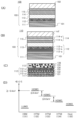
도 1의 (A)는 본 발명의 일 형태의 발광 소자(100)의 단면도이다. 발광 소자(100)는 적어도 한 쌍의 전극(전극(101) 및 전극(102))과, 상기 한 쌍의 전극 사이에 제공된 EL층(103)을 포함한다.1(A) is a cross-sectional view of a
EL층(103)은 적어도 발광층(113) 및 정공 수송층(112)을 포함한다. 또한 EL층(103)은 정공 주입층(111), 전자 수송층(114), 및 전자 주입층(115) 등의 기능층을 포함한다.The
본 실시형태에서는, 전극(101)이 양극으로서 기능하고 전극(102)이 음극으로서 기능하는 것으로 가정하여 설명하지만, 발광 소자의 구조는 이에 한정되지 않는다. 즉, 전극(101)이 음극으로서 기능할 수 있고 전극(102)이 양극으로서 기능할 수 있다. 그 경우, 적층 순서가 뒤바뀐다. 바꿔 말하면, 양극 측으로부터 정공 주입층, 정공 수송층, 발광층, 전자 수송층, 및 전자 주입층이 이 순서대로 적층되어도 좋다.In this embodiment, description is made on the assumption that the
EL층(103)의 구조는 상술한 것에 한정되지 않고, 예를 들어 EL층(103)은 정공 또는 전자 수송성을 향상 또는 억제할 수 있고, 여기자의 확산을 억제할 수 있는 기능층을 포함하여도 좋다. 상기 기능층은 각각 단층이어도 좋고 적층이어도 좋다.The structure of the
발광 소자(100)에서, EL층(103)에서의 적어도 하나의 층은, 본 발명의 일 형태의 유기 화합물을 함유한다. 또한 유기 화합물은 발광층(113)에 함유되는 것이 바람직하고, 정공 수송층(112)에 함유되는 것이 더 바람직하다.In the
본 발명의 일 형태의 유기 화합물이 발광층(113)에 함유되는 경우, 상기 유기 화합물은 높은 정공 수송성 및 넓은 밴드 갭을 가지기 때문에 상기 유기 화합물을 호스트 재료로서 사용할 수 있다.When the organic compound of one embodiment of the present invention is contained in the
본 발명의 일 형태의 유기 화합물이 정공 수송층(112)에 함유되는 경우, 상기 유기 화합물은 높은 정공 수송성 및 넓은 밴드 갭을 가지기 때문에, 발광 효율이 높고 수명이 긴 발광 소자를 제공할 수 있다. 특히, 유기 화합물은, 정공 주입층(111)이 정공 수송층(112)과 전극(101) 사이에 제공되고, 전극으로부터의 정공의 주입을 용이하게 하는 억셉터성을 가지는 유기 화합물을 포함하는 경우에 사용되는 것이 바람직하다.When the organic compound of one embodiment of the present invention is contained in the
<발광 소자의 구조예 1><Structural Example 1 of Light-Emitting Device>
억셉터성을 가지는 유기 화합물을 사용하여 정공 주입을 수행하는 경우, 정공 주입층(111)과 접촉하는 정공 수송층(112)에 함유되는 화합물은, 억셉터성을 가지는 유기 화합물에 의한 전자의 추출을 용이하게 하기 위하여, HOMO 준위가 비교적 높은 정공 수송 재료인 것이 바람직하다. 그러나 정공은, HOMO 준위가 높은 정공 수송 재료로부터 발광층(113)으로 쉽게 주입될 수 없다. 발광층(113)을, HOMO 준위가 높은 정공 수송 재료로 이루어진 정공 수송층(112)과 접촉하도록 형성하면, 그 계면에 캐리어가 축적되어, 발광 소자의 수명 및 효율의 저하를 일으킬 수 있다. 따라서, 본 발명의 일 형태의 유기 화합물을 함유하는 층을 발광층(113)과, HOMO 준위가 높은 정공 수송 재료 사이에 제공하면, 정공을 발광층에 쉽게 주입할 수 있고, 발광 소자의 수명 및 효율을 향상시킬 수 있다.When hole injection is performed using an organic compound having an acceptor property, the compound contained in the
이 경우의 발광 소자의 구조는, 도 1의 (B) 내지 (D)를 참조하여 설명한다. 여기서는, 정공 주입 재료(131)로서 억셉터성을 가지는 유기 화합물을 사용하고, 정공 주입 재료(131)의 LUMO 준위가 제 1 정공 수송 재료(132)의 HOMO 준위보다 낮은 경우에 대하여 설명한다. 이 경우의 재료의 HOMO 준위 및 LUMO 준위의 상관을 도 1의 (D)에 모식적으로 나타내었다. 도 1의 (C) 및 (D)에서의 용어 및 부호를 이하에 열거한다.The structure of the light emitting element in this case will be described with reference to FIGS. 1(B) to (D). Here, a case in which an organic compound having an acceptor property is used as the
HIM(131): 정공 주입 재료(131);HIM 131:
HTM(132): 제 1 정공 수송 재료(132);HTM 132: first
HTM(133): 제 2 정공 수송 재료(133);HTM 133: second
HTM(134): 제 3 정공 수송 재료(134);HTM 134: third
Host(135): 호스트 재료(135); 및Host 135:
게스트 재료(136).Guest Material (136).
도 1의 (B)에 도시된 바와 같이, 정공 수송층(112)은 복수의 층의 적층 구조를 가져도 좋다. 구체적으로, 정공 수송층(112)이, 정공 주입층(111) 측으로부터 제 1 정공 수송 재료(132)를 함유하는 제 1 정공 수송층(112-a) 및 제 2 정공 수송 재료(133)를 함유하는 제 2 정공 수송층(112-b)을 포함하는 구조를 채용하여도 좋다. 본 발명의 일 형태의 유기 화합물은 제 2 정공 수송 재료(133)로서 사용되어도 좋다. 이러한 구조의 경우, 제 2 정공 수송 재료(133)의 HOMO 준위가 제 1 정공 수송 재료(132)의 HOMO 준위보다 낮으면, 수명이 길고 효율이 높은 발광 소자가 달성된다. 또한 제 1 정공 수송 재료(132)의 HOMO 준위가 -5.4eV 이상인 경우, 정공 주입 재료(131)로부터 전자를 쉽게 추출할 수 있어 바람직하다(도 1의 (D) 참조).As shown in FIG. 1(B), the
도 1의 (D)에 나타낸 바와 같이, 제 1 정공 수송 재료(132)의 HOMO 준위와 제 2 정공 수송 재료(133)의 HOMO 준위의 차이는 0.3eV 이하인 것이 바람직하고 0.2eV 이하인 것이 더 바람직하고, 이 경우, 정공이 제 1 정공 수송층(112-a)으로부터 제 2 정공 수송층(112-b)으로 쉽게 주입될 수 있다. 본 발명의 일 형태의 유기 화합물의 HOMO 준위는 약 -5.5eV이기 때문에, 유기 화합물을 제 2 정공 수송 재료(133)로서 적합하게 사용할 수 있다.As shown in (D) of FIG. 1, the difference between the HOMO level of the first
정공 수송층(112)은 제 2 정공 수송층(112-b)과 발광층(113) 사이에 제 3 정공 수송층(112-c)을 더 포함하여도 좋고, 제 3 정공 수송층(112-c)은 제 3 정공 수송 재료(134)를 함유하여도 좋다(도 1의 (B) 및 (C) 참조). 이 경우, 도 1의 (D)에 나타낸 바와 같이, 제 3 정공 수송 재료(134)의 HOMO 준위는 제 2 정공 수송층(112-b)에 함유되는 본 발명의 일 형태의 정공 수송 재료의 HOMO 준위보다 낮은 것이 바람직하고, HOMO 준위의 차이는 0.3eV 이하인 것이 바람직하고 0.2eV 이하인 것이 더 바람직하다. 본 발명의 일 형태의 유기 화합물의 HOMO 준위는 약 -5.5eV이기 때문에, 상기 유기 화합물을 제 3 정공 수송 재료(134)로서 적합하게 사용할 수 있다.The
제 3 정공 수송 재료(134)의 HOMO 준위는 호스트 재료(135)의 HOMO 준위 이하인 것이 바람직하고, 이 경우, 정공이 발광층으로 적합하게 수송되어 수명 및 효율이 높아진다.The HOMO level of the third
또한 도 1의 (D)에서는, 정공 주입 재료(131)의 LUMO 준위가 호스트 재료(135)의 HOMO 준위보다 낮지만, 이 관계에 한정은 없다. 즉, 정공 주입 재료(131)의 LUMO 준위는 호스트 재료(135)의 HOMO 준위 이상이어도 좋다. 또한 호스트 재료(135)의 HOMO 준위가 제 1 정공 수송 재료(132)의 HOMO 준위보다 높은 것, 호스트 재료(135)의 HOMO 준위가 제 2 정공 수송 재료(133)의 HOMO 준위보다 높은 것, 또한 호스트 재료(135)의 HOMO 준위가 제 3 정공 수송 재료(134)의 HOMO 준위보다 높은 것이 가능하다. 또한 제 1 정공 수송 재료(132)의 HOMO 준위가 제 2 정공 수송 재료(133)의 HOMO 준위보다 낮아도 좋다. 또한 제 2 정공 수송 재료(133)의 HOMO 준위는 제 3 정공 수송 재료(134)의 HOMO 준위보다 낮아도 좋다. 또한 제 1 정공 수송 재료(132)의 HOMO 준위는 제 3 정공 수송 재료(134)의 HOMO 준위보다 낮아도 좋다.In FIG. 1(D), the LUMO level of the
또한 게스트 재료(136)의 HOMO 준위가 호스트 재료(135)의 HOMO 준위보다 높은 경우, 게스트 재료(136)에 주입된 정공의 비율은 정공 수송층의 HOMO 준위의 위치에 따라 증가되고, 또한 정공이 게스트 재료(136)에 트랩되어, 불균일하게 위치하는 발광 영역으로 인한 수명의 저하가 일어날 수 있다. 본 발명의 발광 소자의 구조를, 이러한 경우, 예를 들어 청색 형광 소자에 적용하는 것이 바람직하다. 특히, 본 발명의 구조는 우수한 청색 형광을 방출하는 방향족 다이아민 화합물, 더 구체적으로는 피렌다이아민 화합물 등에 바람직하게 사용되고, 수명, 효율, 및 색도가 우수한 발광 소자가 달성된다.Also, when the HOMO level of the
전자 수송층(114)은, 반드시 도 1의 (A)에 도시된 바와 같은 단층일 필요는 없고, 복수의 층의 적층 구조를 가져도 좋다. 전자 수송층(114)은 복수의 재료로 형성된 혼합막이어도 좋다. 구체적으로는, 도 1의 (B)에 도시된 바와 같이, 전자 수송층(114)이, 발광층(113) 측으로부터 제 1 전자 수송층(114-b) 및 제 2 전자 수송층(114-a)을 포함하여도 좋다. 이러한 구조는, 전자 수송층(114-a)으로의 전자 주입층(115)의 전자 주입성, 및 전자 수송층(114-b) 및 전자 수송층(114-a)의 전자 수송성을 조정할 수 있어 바람직하다.The
<발광 소자의 구조예 2><Structural Example 2 of Light-Emitting Device>
다음에, 청색 형광 소자의 구조예에 대하여 도 2의 (A) 내지 (C)를 참조하여 설명한다.Next, a structural example of a blue fluorescent element will be described with reference to Figs. 2(A) to (C).
도 2의 (A)에 도시된 발광 소자(120)는, 적어도 정공 수송층(112)에 본 발명의 일 형태의 유기 화합물을 함유한다. 도 2의 (B)는, 발광층(113)의 재료의 구조예를 도시한 것이다. 도 2의 (C)는, 발광층(113)의 재료의 에너지 준위의 상관을 모식적으로 나타낸 것이다.In the
여기서는, 호스트 재료(121)의 T1 준위가 게스트 재료(122)의 T1 준위보다 낮은 경우에 대하여 설명한다. 도 2의 (C)에서의 용어 및 부호를 이하에 열거한다. 또한 호스트 재료(121)의 T1 준위가 게스트 재료(122)의 T1 준위보다 높아도 좋다.Here, a case where the T1 level of the
Host(121): 호스트 재료(121);Host 121:
Guest(122): 게스트 재료(122)(형광 재료);Guest 122: guest material 122 (fluorescent material);
SFH: 호스트 재료(121)의 S1 준위;S FH : S1 level of the
TFH: 호스트 재료(121)의 T1 준위;T FH : T1 level of the
SFG: 게스트 재료(122)(형광 재료)의 S1 준위; 및S FG : S1 level of the guest material 122 (fluorescent material); and
TFG: 게스트 재료(122)(형광 재료)의 T1 준위.T FG : T1 level of the guest material 122 (fluorescent material).
호스트 재료(121)는, 삼중항 여기 에너지를 삼중항-삼중항 소멸(TTA: triplet-triplet annihilation)에 의하여 단일항 여기 에너지로 변환하는 기능을 가지는 것이 바람직하고, 이에 의하여, 통상 시에는 형광에 기여하지 않고 발광층(113)에서 생성되는 삼중항 여기 에너지가, 호스트 재료(121)에서의 단일항 여기 에너지로 부분적으로 변환될 수 있다. 단일항 여기 에너지는 게스트 재료(122)로 이동하여(도 2의 (C)에서의 루트 E1 참조), 형광으로서 추출될 수 있다. 따라서 형광 소자의 발광 효율이 향상될 수 있다. 또한 TTA에 의하여 생성된 형광은 수명이 긴 삼중항 여기 상태를 거쳐 얻어지기 때문에, 지연 형광이 관찰된다.The
발광층(113)에서 단일항 여기 에너지를 게스트 재료(122)로 효율적으로 이동시키기 위해서는, 도 2의 (C)에 도시된 바와 같이, 호스트 재료(121)의 단일항 여기 에너지(S1 준위)의 가장 낮은 준위가 게스트 재료(122)의 S1 준위보다 높은 것이 바람직하다. 또한 호스트 재료(121)의 삼중항 여기 에너지(T1 준위)의 가장 낮은 준위가 게스트 재료(122)의 T1 준위보다 낮은 것이 바람직하다(도 2의 (C)에서의 루트 E2 참조). 이러한 구조에 의하여, 발광층(113)에서 TTA를 효율적으로 일으킬 수 있다.In order to efficiently move the singlet excitation energy from the
또한 호스트 재료(121)의 T1 준위는, 발광층(113)에 접촉하는 정공 수송층(112)(도 2의 (A)에서의 정공 수송층(112-c))에 사용된 재료의 T1 준위보다 낮은 것이 바람직하다. 즉, 정공 수송층(112)은 여기자의 확산을 억제하는 기능을 가지는 것이 바람직하다. 이러한 구조에 의하여, 발광층(113)에서 생성된 삼중항 여기자가 정공 수송층(112)으로 확산되는 것을 억제할 수 있어, 발광 효율이 높은 소자를 제공할 수 있다.In addition, the T1 level of the
본 발명의 일 형태의 유기 화합물은 높은 T1 준위 및 높은 정공 수송성을 가지기 때문에, 발광 소자에서의 TTA를 이용한 정공 수송 재료로서 적합하게 사용할 수 있다. 또한 본 발명의 일 형태의 유기 화합물은 호스트 재료(121)로서도 사용할 수 있다.Since the organic compound of one embodiment of the present invention has a high T1 level and high hole transporting properties, it can be suitably used as a hole transporting material using TTA in a light emitting device. In addition, the organic compound of one embodiment of the present invention can also be used as the
유기 화합물의 가장 낮은 단일항 여기 에너지 준위는 유기 화합물에서의 단일항 기저 상태로부터 가장 낮은 단일항 여기 상태로의 전이 시의 흡수 스펙트럼으로부터 관찰될 수 있다. 또는, 가장 낮은 단일항 여기 에너지 준위를 유기 화합물의 형광 스펙트럼의 피크 파장으로부터 추정하여도 좋다. 또한, 가장 낮은 삼중항 여기 에너지 준위는 유기 화합물에서의 단일항 기저 상태로부터 가장 낮은 삼중항 여기 상태로의 전이 시의 흡수 스펙트럼으로부터 관찰될 수 있지만, 이 전이는 금지된 전이이기 때문에, 관찰하기 어려운 경우가 있다. 이러한 경우, 가장 낮은 삼중항 여기 에너지 준위를 유기 화합물의 인광 스펙트럼의 피크 파장으로부터 추정하여도 좋다.The lowest singlet excitation energy level of an organic compound can be observed from an absorption spectrum at the transition from a singlet ground state to the lowest singlet excited state in the organic compound. Alternatively, the lowest singlet excitation energy level may be estimated from the peak wavelength of the fluorescence spectrum of the organic compound. In addition, the lowest triplet excitation energy level can be observed from the absorption spectrum at the transition from the singlet ground state to the lowest triplet excited state in organic compounds, but since this transition is a forbidden transition, it is difficult to observe. There are cases. In this case, the lowest triplet excitation energy level may be estimated from the peak wavelength of the phosphorescence spectrum of the organic compound.
<재료><Material>
다음으로 본 발명의 일 형태의 발광 소자의 구성 요소에 대하여 이하에서 자세히 설명한다.Next, components of the light emitting element of one embodiment of the present invention will be described in detail below.
<<발광층>><<light emitting layer>>
발광층(113)에서는, 호스트 재료(121)의 중량비가 적어도 게스트 재료(122)의 중량비보다 높고, 게스트 재료(122)(형광 재료)가 호스트 재료(121) 내에 분산된다. 또한 발광층(113)에서, 호스트 재료(121)는 일종의 화합물 또는 복수의 화합물로 이루어져도 좋다.In the
발광층(113)에서, 게스트 재료(122)는 이들에 특별히 한정되지 않지만, 안트라센 유도체, 테트라센 유도체, 크리센 유도체, 페난트렌 유도체, 피렌 유도체, 페릴렌 유도체, 스틸벤 유도체, 아크리돈 유도체, 쿠마린 유도체, 페녹사진 유도체, 또는 페노싸이아진 유도체 등이 바람직하고, 예를 들어 다음 재료 중 임의의 재료를 사용할 수 있다.In the
예에는 5,6-비스[4-(10-페닐-9-안트릴)페닐]-2,2'-바이피리딘(약칭: PAP2BPy), 5,6-비스[4'-(10-페닐-9-안트릴)바이페닐-4-일]-2,2'-바이피리딘(약칭: PAPP2BPy), N,N '-다이페닐-N,N '-비스[4-(9-페닐-9H-플루오렌-9-일)페닐]피렌-1,6-다이아민(약칭: 1,6FLPAPrn), N,N '-비스(3-메틸페닐)-N,N '-비스[3-(9-페닐-9H-플루오렌-9-일)페닐]피렌-1,6-다이아민(약칭: 1,6mMemFLPAPrn), N,N '-비스[4-(9-페닐-9H-플루오렌-9-일)페닐]-N,N'-비스(4-tert-뷰틸페닐)피렌-1,6-다이아민(약칭: 1,6tBu-FLPAPrn), N,N '-비스[4-(9-페닐-9H-플루오렌-9-일)페닐]-N,N'-다이페닐-3,8-다이사이클로헥실피렌-1,6-다이아민(약칭: ch-1,6FLPAPrn), N,N '-비스[4-(9H-카바졸-9-일)페닐]-N,N'-다이페닐스틸벤-4,4'-다이아민(약칭: YGA2S), 4-(9H-카바졸-9-일)-4'-(10-페닐-9-안트릴)트라이페닐아민(약칭: YGAPA), 4-(9H-카바졸-9-일)-4'-(9,10-다이페닐-2-안트릴)트라이페닐아민(약칭: 2YGAPPA), N,9-다이페닐-N-[4-(10-페닐-9-안트릴)페닐]-9H-카바졸-3-아민(약칭: PCAPA), 페릴렌, 2,5,8,11-테트라(tert-뷰틸)페릴렌(약칭: TBP), 4-(10-페닐-9-안트릴)-4'-(9-페닐-9H-카바졸-3-일)트라이페닐아민(약칭: PCBAPA), N,N ''-(2-tert-뷰틸안트라센-9,10-다이일다이-4,1-페닐렌)비스[N,N',N'-트라이페닐-1,4-페닐렌다이아민](약칭: DPABPA), N,9-다이페닐-N-[4-(9,10-다이페닐-2-안트릴)페닐]-9H-카바졸-3-아민(약칭: 2PCAPPA), N-[4-(9,10-다이페닐-2-안트릴)페닐]-N,N',N'-트라이페닐-1,4-페닐렌다이아민(약칭: 2DPAPPA), N,N,N ',N',N'',N'',N''',N'''-옥타페닐다이벤조[g,p]크리센-2,7,10,15-테트라아민(약칭: DBC1), 쿠마린 30, N-(9,10-다이페닐-2-안트릴)-N,9-다이페닐-9H-카바졸-3-아민(약칭: 2PCAPA), N-[9,10-비스(1,1'-바이페닐-2-일)-2-안트릴]-N,9-다이페닐-9H-카바졸-3-아민(약칭: 2PCABPhA), N-(9,10-다이페닐-2-안트릴)-N,N',N'-트라이페닐-1,4-페닐렌다이아민(약칭: 2DPAPA), N-[9,10-비스(1,1'-바이페닐-2-일)-2-안트릴]-N,N',N'-트라이페닐-1,4-페닐렌다이아민(약칭: 2DPABPhA), 9,10-비스(1,1'-바이페닐-2-일)-N-[4-(9H-카바졸-9-일)페닐]-N-페닐안트라센-2-아민(약칭: 2YGABPhA), N,N,9-트라이페닐안트라센-9-아민(약칭: DPhAPhA), 쿠마린 6, 쿠마린 545T, N,N '-다이페닐퀴나크리돈(약칭: DPQd), 루브렌, 2,8-다이-tert-뷰틸-5,11-비스(4-tert-뷰틸페닐)-6,12-다이페닐테트라센(약칭: TBRb), Nile red, 5,12-비스(1,1'-바이페닐-4-일)-6,11-다이페닐테트라센(약칭: BPT), 2-(2-{2-[4-(다이메틸아미노)페닐]에텐일}-6-메틸-4H-피란-4-일리덴)프로페인다이나이트릴(약칭: DCM1), 2-{2-메틸-6-[2-(2,3,6,7-테트라하이드로-1H,5H-벤조[ij]퀴놀리진-9-일)에텐일]-4H-피란-4-일리덴}프로페인다이나이트릴(약칭: DCM2), N,N,N ',N'-테트라키스(4-메틸페닐)테트라센-5,11-다이아민(약칭: p-mPhTD), 7,14-다이페닐-N,N,N ',N'-테트라키스(4-메틸페닐)아세나프토[1,2-a]플루오란텐-3,10-다이아민(약칭: p-mPhAFD), 2-{2-아이소프로필-6-[2-(1,1,7,7-테트라메틸-2,3,6,7-테트라하이드로-1H,5H-벤조[ij]퀴놀리진-9-일)에텐일]-4H-피란-4-일리덴}프로페인다이나이트릴(약칭: DCJTI), 2-{2-tert-뷰틸-6-[2-(1,1,7,7-테트라메틸-2,3,6,7-테트라하이드로-1H,5H-벤조[ij]퀴놀리진-9-일)에텐일]-4H-피란-4-일리덴}프로페인다이나이트릴(약칭: DCJTB), 2-(2,6-비스{2-[4-(다이메틸아미노)페닐]에텐일}-4H-피란-4-일리덴)프로페인다이나이트릴(약칭: BisDCM), 2-{2,6-비스[2-(8-메톡시-1,1,7,7-테트라메틸-2,3,6,7-테트라하이드로-1H,5H-벤조[ij]퀴놀리진-9-일)에텐일]-4H-피란-4-일리덴}프로페인다이나이트릴(약칭: BisDCJTM), 및 5,10,15,20-테트라페닐비스벤조[5,6]인데노[1,2,3-cd:1',2',3'-lm]페릴렌이 포함된다.Examples include 5,6-bis[4-(10-phenyl-9-anthryl)phenyl]-2,2'-bipyridine (abbreviation: PAP2BPy), 5,6-bis[4'-(10-phenyl- 9-anthryl)biphenyl-4-yl]-2,2'-bipyridine (abbreviation: PAPP2BPy), N , N ' -diphenyl- N , N ' -bis[4-(9-phenyl-9 H -fluoren-9-yl)phenyl]pyrene-1,6-diamine (abbreviation: 1,6FLPAPrn), N , N ' -bis (3-methylphenyl) - N , N ' -bis [3- (9-) Phenyl- 9H -fluoren-9-yl)phenyl]pyrene-1,6-diamine (abbreviation: 1,6mMemFLPAPrn), N , N ' -bis[4-(9-phenyl - 9H-fluorene- 9-yl)phenyl] -N , N' -bis(4- tert -butylphenyl)pyrene-1,6-diamine (abbreviation: 1,6tBu-FLPAPrn), N , N' - bis[4-(9 -phenyl- 9H -fluoren-9-yl)phenyl] -N , N' -diphenyl-3,8-dicyclohexylpyrene-1,6-diamine (abbreviation: ch-1,6FLPAPrn), N , N' - bis[4-( 9H -carbazol-9-yl)phenyl] -N , N' -diphenylstilbene-4,4'-diamine (abbreviation: YGA2S), 4-(9 H -Carbazol-9-yl)-4'-(10-phenyl-9-anthryl)triphenylamine (abbreviation: YGAPA), 4-( 9H -carbazol-9-yl)-4'-(9 ,10-diphenyl-2-anthryl)triphenylamine (abbreviation: 2YGAPPA), N ,9-diphenyl- N- [4-(10-phenyl-9-anthryl)phenyl]-9 H -carbazole -3-amine (abbreviation: PCAPA), perylene, 2,5,8,11-tetra( tert -butyl)perylene (abbreviation: TBP), 4-(10-phenyl-9-anthryl)-4' -(9-phenyl- 9H -carbazol-3-yl)triphenylamine (abbreviation: PCBAPA), N , N '' -(2- tert -butylanthracene-9,10-diyldi-4,1 -phenylene)bis[ N , N' , N' -triphenyl-1,4-phenylenediamine] (abbreviation: DPABPA), N ,9-diphenyl- N- [4-(9,10-di) Phenyl-2-anthryl)phenyl]-9 H -carbazol-3-amine (abbreviation: 2PCAPPA), N- [4-(9,10-diphenyl-2-anthryl)phenyl] -N , N' , N' -triphenyl-1,4-phenylenediamine (abbreviation: 2DPAPPA), N , N , N ' , N ' , N'' , N'' , N''' , N''' -octa Phenyldibenzo[ g , p ]chrysene-2,7,10,15-tetraamine (abbreviation: DBC1), coumarin 30, N- (9,10-diphenyl-2-anthryl) -N ,9- Diphenyl- 9H -carbazol-3-amine (abbreviation: 2PCAPA), N- [9,10-bis(1,1′-biphenyl-2-yl)-2-anthryl] -N ,9- Diphenyl- 9H -carbazol-3-amine (abbreviation: 2PCABPhA), N- (9,10-diphenyl-2-anthryl) -N , N ', N' -triphenyl-1,4-phenyl Rendiamine (abbreviation: 2DPAPA), N- [9,10-bis(1,1'-biphenyl-2-yl)-2-anthryl] -N , N' , N' -triphenyl-1, 4-phenylenediamine (abbreviation: 2DPABPhA), 9,10-bis(1,1'-biphenyl-2-yl) -N- [4-(9 H -carbazol-9-yl)phenyl]- N -phenylanthracene-2-amine (abbreviation: 2YGABPhA), N , N ,9-triphenylanthracene-9-amine (abbreviation: DPhAPhA), coumarin 6, coumarin 545T, N , N ' -diphenylquinacridone ( Abbreviation: DPQd), rubrene, 2,8-di- tert -butyl-5,11-bis(4- tert -butylphenyl)-6,12-diphenyltetracene (abbreviation: TBRb), Nile red, 5 ,12-bis(1,1′-biphenyl-4-yl)-6,11-diphenyltetracene (abbreviation: BPT), 2-(2-{2-[4-(dimethylamino)phenyl] Ethenyl} -6-methyl-4 H -pyran-4-ylidene) propanedinitrile (abbreviation: DCM1), 2-{2-methyl-6-[2-(2,3,6,7- tetrahydro- 1H , 5H -benzo[ ij ]quinolizin-9-yl)ethenyl] -4H -pyran-4-ylidene}propanedinitrile (abbreviation: DCM2), N , N , N ' , N' -tetrakis (4-methylphenyl) tetracene-5,11-diamine (abbreviation: p-mPhTD), 7,14-diphenyl- N , N , N ' , N' -tetrakis ( 4-methylphenyl)acenaphtho[1,2-a]fluoranthene-3,10-diamine (abbreviation: p-mPhAFD), 2-{2-isopropyl-6-[2-(1,1, 7,7-tetramethyl-2,3,6,7-tetrahydro-1 H ,5 H -benzo[ ij ]quinolizin-9-yl)ethenyl] -4H -pyran-4-ylidene} Propanedinitrile (abbreviation: DCJTI), 2-{2- tert -butyl-6-[2-(1,1,7,7-tetramethyl-2,3,6,7-tetrahydro-1 H , 5H -benzo[ ij ]quinolizin-9-yl)ethenyl] -4H -pyran-4-ylidene}propanedinitrile (abbreviation: DCJTB), 2-(2,6-bis{ 2-[4-(dimethylamino)phenyl]ethenyl}-4 H -pyran-4-ylidene)propanedinitrile (abbreviation: BisDCM), 2-{2,6-bis[2-(8) -methoxy-1,1,7,7-tetramethyl-2,3,6,7-tetrahydro-1 H ,5 H -benzo[ ij ]quinolizin-9-yl)ethenyl]-4 H -pyran-4-ylidene} propanedinitrile (abbreviation: BisDCJTM), and 5,10,15,20-tetraphenylbisbenzo[5,6]indeno[1,2,3- cd :1',2',3'- lm ]perylene.
또한 발광층(113)은 호스트 재료(121) 및 게스트 재료(122) 외의 재료를 포함하여도 좋다.In addition, the
발광층(113)에 사용할 수 있는 재료에 특별한 한정은 없지만, 예를 들어 다음 재료 중 임의의 재료를 사용할 수 있다: 트리스(8-퀴놀리놀레이토)알루미늄(III)(약칭: Alq), 트리스(4-메틸-8-퀴놀리놀레이토)알루미늄(III)(약칭: Almq3), 비스(10-하이드록시벤조[h]퀴놀리네이토)베릴륨(II)(약칭: BeBq2), 비스(2-메틸-8-퀴놀리놀레이토)(4-페닐페놀레이토)알루미늄(III)(약칭: BAlq), 비스(8-퀴놀리놀레이토)아연(II)(약칭: Znq), 비스[2-(2-벤즈옥사졸릴)페놀레이토]아연(II)(약칭: ZnPBO), 및 비스[2-(2-벤조싸이아졸릴)페놀레이토]아연(II)(약칭: ZnBTZ) 등의 금속 착체; 2-(4-바이페닐릴)-5-(4-tert-뷰틸페닐)-1,3,4-옥사다이아졸(약칭: PBD), 1,3-비스[5-(p-tert-뷰틸페닐)-1,3,4-옥사다이아졸-2-일]벤젠(약칭: OXD-7), 3-(4-바이페닐릴)-4-페닐-5-(4-tert-뷰틸페닐)-1,2,4-트라이아졸(약칭: TAZ), 2,2',2''-(1,3,5-벤젠트라이일)-트리스(1-페닐-1H-벤즈이미다졸)(약칭: TPBI), 바소페난트롤린(약칭: BPhen), 바소큐프로인(약칭: BCP), 및 9-[4-(5-페닐-1,3,4-옥사다이아졸-2-일)페닐]-9H-카바졸(약칭: CO11) 등의 헤테로고리 화합물; 및 4,4'-비스[N-(1-나프틸)-N-페닐아미노]바이페닐(약칭: NPB 또는 α-NPD), N,N '-비스(3-메틸페닐)-N,N'-다이페닐-[1,1'-바이페닐]-4,4'-다이아민(약칭: TPD), 및 4,4'-비스[N-(스파이로-9,9'-바이플루오렌-2-일)-N-페닐아미노]바이페닐(약칭: BSPB) 등의 방향족 아민 화합물. 또한, 안트라센 유도체, 페난트렌 유도체, 피렌 유도체, 크리센 유도체, 및 다이벤조[g,p]크리센 유도체 등의 축합 다환 방향족 화합물을 사용할 수 있다. 이들의 구체적인 예에는 9,10-다이페닐안트라센(약칭: DPAnth), N,N-다이페닐-9-[4-(10-페닐-9-안트릴)페닐]-9H-카바졸-3-아민(약칭: CzA1PA), 4-(10-페닐-9-안트릴)트라이페닐아민(약칭: DPhPA), 4-(9H-카바졸-9-일)-4'-(10-페닐-9-안트릴)트라이페닐아민(약칭: YGAPA), N,9-다이페닐-N-[4-(10-페닐-9-안트릴)페닐]-9H-카바졸-3-아민(약칭: PCAPA), N,9-다이페닐-N-{4-[4-(10-페닐-9-안트릴)페닐]페닐}-9H-카바졸-3-아민(약칭: PCAPBA), N,9-다이페닐-N-(9,10-다이페닐-2-안트릴)-9H-카바졸-3-아민(약칭: 2PCAPA), 6,12-다이메톡시-5,11-다이페닐크리센, N,N,N',N',N'',N'',N''',N'''-옥타페닐다이벤조[g,p]크리센-2,7,10,15-테트라아민(약칭: DBC1), 9-페닐-3-[4-(10-페닐-9-안트릴)페닐]-9H-카바졸(약칭: PCzPA), 3,6-다이페닐-9-[4-(10-페닐-9-안트릴)페닐]-9H-카바졸(약칭: DPCzPA), 9,10-비스(3,5-다이페닐페닐)안트라센(약칭: DPPA), 9,10-다이(2-나프틸)안트라센(약칭: DNA), 2-tert-뷰틸-9,10-다이(2-나프틸)안트라센(약칭: t-BuDNA), 9,9'-바이안트릴(약칭: BANT), 9,9'-(스틸벤-3,3'-다이일)다이페난트렌(약칭: DPNS), 9,9'-(스틸벤-4,4'-다이일)다이페난트렌(약칭: DPNS2), 및 1,3,5-트라이(1-피렌일)벤젠(약칭: TPB3)이 포함된다. 이들 물질 및 공지의 물질 중에서, 게스트 재료(122)의 에너지 갭보다 넓은 에너지 갭을 가지는 하나 이상의 물질을 선택하는 것이 바람직하다.There is no particular limitation on the material that can be used for the light emitting layer 113, but any of the following materials can be used, for example: tris(8-quinolinolato)aluminum(III) (abbreviation: Alq), tris( 4-methyl-8-quinolinolato) aluminum (III) (abbreviation: Almq 3 ), bis (10-hydroxybenzo [ h ] quinolinato) beryllium (II) (abbreviation: BeBq 2 ), bis ( 2-methyl-8-quinolinolato)(4-phenylphenolato)aluminum(III) (abbreviation: BAlq), bis(8-quinolinolato)zinc(II) (abbreviation: Znq), bis[2 Metal complexes such as -(2-benzoxazolyl)phenolato]zinc(II) (abbreviation: ZnPBO), and bis[2-(2-benzothiazolyl)phenolato]zinc(II) (abbreviation: ZnBTZ) ; 2-(4-biphenylyl)-5-(4- tert -butylphenyl)-1,3,4-oxadiazole (abbreviation: PBD), 1,3-bis[5-( p - tert -butyl Phenyl) -1,3,4-oxadiazol-2-yl] benzene (abbreviation: OXD-7), 3- (4-biphenylyl) -4-phenyl-5- (4- tert -butylphenyl) -1,2,4-triazole (abbreviation: TAZ), 2,2',2''-(1,3,5-benzenetriyl)-tris(1-phenyl- 1H -benzimidazole) ( Abbreviation: TPBI), vasophenanthroline (abbreviation: BPhen), vasocuproin (abbreviation: BCP), and 9-[4-(5-phenyl-1,3,4-oxadiazol-2-yl) heterocyclic compounds such as phenyl] -9 H -carbazole (abbreviation: CO11); and 4,4′-bis[ N- (1-naphthyl) -N -phenylamino]biphenyl (abbreviation: NPB or α-NPD), N , N′ - bis(3-methylphenyl) -N , N′ -Diphenyl-[1,1'-biphenyl]-4,4'-diamine (abbreviation: TPD), and 4,4'-bis[ N- (spiro-9,9'-bifluorene- Aromatic amine compounds such as 2-yl) -N -phenylamino]biphenyl (abbreviation: BSPB). In addition, condensed polycyclic aromatic compounds such as anthracene derivatives, phenanthrene derivatives, pyrene derivatives, chrysene derivatives, and dibenzo[ g , p ]chrysene derivatives can be used. Specific examples thereof include 9,10-diphenylanthracene (abbreviation: DPAnth), N , N -diphenyl-9-[4-(10-phenyl-9-anthryl)phenyl] -9H -carbazole-3 -Amine (abbreviation: CzA1PA), 4-(10-phenyl-9-anthryl)triphenylamine (abbreviation: DPhPA), 4-( 9H -carbazol-9-yl)-4'-(10-phenyl) -9-anthryl)triphenylamine (abbreviation: YGAPA), N ,9-diphenyl- N- [4-(10-phenyl-9-anthryl)phenyl] -9H -carbazol-3-amine ( Abbreviation: PCAPA), N ,9-diphenyl- N- {4-[4-(10-phenyl-9-anthryl)phenyl]phenyl}-9 H -carbazol-3-amine (abbreviation: PCAPBA), N ,9-diphenyl- N- (9,10-diphenyl-2-anthryl) -9H -carbazol-3-amine (abbreviation: 2PCAPA), 6,12-dimethoxy-5,11- Diphenylchrysene, N , N , N' , N' , N'', N'' , N''' , N''' -octaphenyldibenzo[ g , p ]chrysene-2,7,10 ,15-tetraamine (abbreviation: DBC1), 9-phenyl-3-[4-(10-phenyl-9-anthryl)phenyl] -9H -carbazole (abbreviation: PCzPA), 3,6-diphenyl -9-[4-(10-phenyl-9-anthryl)phenyl] -9H -carbazole (abbreviation: DPCzPA), 9,10-bis(3,5-diphenylphenyl)anthracene (abbreviation: DPPA) , 9,10-di (2-naphthyl) anthracene (abbreviation: DNA), 2- tert -butyl-9,10-di (2-naphthyl) anthracene (abbreviation: t-BuDNA), 9,9'- Bianthryl (abbreviation: BANT), 9,9'-(stilbene-3,3'-diyl)diphenanthrene (abbreviation: DPNS), 9,9'-(stilbene-4,4'-diyl) 1) diphenanthrene (abbreviation: DPNS2), and 1,3,5-tri(1-pyrenyl)benzene (abbreviation: TPB3). Among these materials and known materials, it is preferable to select one or more materials having an energy gap wider than that of the
또한, 발광층(113)은 2층 이상이 적층된 구조를 가질 수 있다. 예를 들어, 제 1 발광층과 제 2 발광층을 정공 수송층 측으로부터 이 순서대로 적층하여 발광층(113)을 형성하는 경우, 제 1 발광층은 정공 수송성을 가지는 물질을 호스트 재료로서 사용하여 형성되고, 제 2 발광층은 전자 수송성을 가지는 물질을 호스트 재료로서 사용하여 형성된다.In addition, the
다음에, 도 1의 (A)에서의 발광 소자(100) 및 도 2의 (A)에서의 발광 소자(120)의 다른 구성의 상세한 사항에 대하여 이하에서 설명한다.Next, details of other configurations of the
<<정공 수송층>><<hole transport layer>>
정공 주입층(111)은 한 쌍의 전극 중 한쪽(전극(101) 또는 전극(102))으로부터의 정공 주입의 배리어를 저감하여 정공 주입을 촉진하는 기능을 가지고, 예를 들어 전이 금속 산화물, 프탈로사이아닌 유도체, 또는 방향족 아민을 사용하여 형성된다. 전이 금속 산화물의 예에는 몰리브데넘 산화물, 바나듐 산화물, 루테늄 산화물, 텅스텐 산화물, 및 망가니즈 산화물이 포함된다. 프탈로사이아닌 유도체의 예에는 프탈로사이아닌 및 금속 프탈로사이아닌이 포함된다. 방향족 아민의 예에는, 벤지딘 유도체 및 페닐렌다이아민 유도체가 포함된다. 폴리싸이오펜 또는 폴리아닐린 등의 고분자 화합물을 사용할 수도 있고, 그 대표적인 예는 자기 도핑된 폴리싸이오펜인 폴리(에틸렌다이옥시싸이오펜)/폴리(스타이렌설폰산)이다.The
정공 주입층(111)으로서, 정공 수송 재료와, 정공 수송 재료로부터 전자를 받는 성질을 가지는 재료의 복합 재료를 함유하는 층을 사용할 수도 있다. 또는 전자 수용성을 가지는 재료를 함유하는 층과 정공 수송 재료를 함유하는 층의 적층을 사용하여도 좋다. 정상(定常) 상태 또는 전계 존재하에서 이들 재료 사이를 전하가 이동할 수 있다. 전자 수용성을 가지는 재료의 예에는 퀴노다이메테인 유도체, 클로라닐 유도체, 및 헥사아자트라이페닐렌 유도체 등의 유기 화합물이 포함된다. 구체적인 예는 7,7,8,8-테트라사이아노-2,3,5,6-테트라플루오로퀴노다이메테인(약칭: F4-TCNQ), 클로라닐, 또는 2,3,6,7,10,11-헥사사이아노-1,4,5,8,9,12-헥사아자트라이페닐렌(약칭: HAT-CN) 등의 전자 흡인기(할로젠기 또는 사이아노기)를 가지는 화합물이다. 또는 제 4족 내지 제 8족 금속의 산화물 등의 전이 금속 산화물을 사용할 수도 있다. 구체적으로는 산화 바나듐, 산화 나이오븀, 산화 탄탈럼, 산화 크로뮴, 산화 몰리브데넘, 산화 텅스텐, 산화 망가니즈, 또는 산화 레늄 등을 사용할 수 있다. 특히, 산화 몰리브데넘은 대기 중에서 안정적이고 흡습성이 낮고 취급하기 쉽기 때문에 바람직하다.As the
정공 수송 재료로서는 전자보다 정공을 더 수송하는 성질을 가지는 재료를 사용할 수 있고, 정공 이동도가 1Х10-6cm2/Vs 이상의 재료가 바람직하다. 구체적으로는 방향족 아민 화합물, 카바졸 유도체, 방향족 탄화수소, 또는 스틸벤 유도체 등을 사용할 수 있다. 또한, 정공 수송 재료는 고분자 화합물이어도 좋다.As the hole transport material, a material having a property of transporting more holes than electrons can be used, and a material having a hole mobility of 1Х10 -6 cm 2 /Vs or more is preferable. Specifically, an aromatic amine compound, a carbazole derivative, an aromatic hydrocarbon, or a stilbene derivative may be used. Further, the hole transport material may be a high molecular compound.
정공 수송성이 높은 방향족 아민 화합물의 예에는 N,N'-다이(p-톨릴)-N,N'-다이페닐-p-페닐렌다이아민(약칭: DTDPPA), 4,4'-비스[N-(4-다이페닐아미노페닐)-N-페닐아미노]바이페닐(약칭: DPAB), N,N'-비스{4-[비스(3-메틸페닐)아미노]페닐}-N,N'-다이페닐-(1,1'-바이페닐)-4,4'-다이아민(약칭: DNTPD), 및 1,3,5-트리스[N-(4-다이페닐아미노페닐)-N-페닐아미노]벤젠(약칭: DPA3B)이 포함된다.Examples of aromatic amine compounds having high hole transport properties include N , N '-di( p -tolyl) -N , N' -diphenyl- p -phenylenediamine (abbreviation: DTDPPA), 4,4'-bis[ N -(4-diphenylaminophenyl) -N -phenylamino]biphenyl (abbreviation: DPAB), N , N' -bis{4-[bis(3-methylphenyl)amino]phenyl} -N , N' -di Phenyl-(1,1'-biphenyl)-4,4'-diamine (abbreviation: DNTPD), and 1,3,5-tris[ N- (4-diphenylaminophenyl) -N -phenylamino] Benzene (abbreviation: DPA3B) is included.
카바졸 유도체의 구체적인 예에는 3-[N-(4-다이페닐아미노페닐)-N-페닐아미노]-9-페닐카바졸(약칭: PCzDPA1), 3,6-비스[N-(4-다이페닐아미노페닐)-N-페닐아미노]-9-페닐카바졸(약칭: PCzDPA2), 3,6-비스[N-(4-다이페닐아미노페닐)-N-(1-나프틸)아미노]-9-페닐카바졸(약칭: PCzTPN2), 3-[N-(9-페닐카바졸-3-일)-N-페닐아미노]-9-페닐카바졸(약칭: PCzPCA1), 3,6-비스[N-(9-페닐카바졸-3-일)-N-페닐아미노]-9-페닐카바졸(약칭: PCzPCA2), 및 3-[N-(1-나프틸)-N-(9-페닐카바졸-3-일)아미노]-9-페닐카바졸(약칭: PCzPCN1)이 있다.Specific examples of the carbazole derivative include 3-[ N- (4-diphenylaminophenyl) -N -phenylamino]-9-phenylcarbazole (abbreviation: PCzDPA1), 3,6-bis[ N- (4-di Phenylaminophenyl) -N -phenylamino]-9-phenylcarbazole (abbreviation: PCzDPA2), 3,6-bis[ N- (4-diphenylaminophenyl) -N- (1-naphthyl)amino]- 9-phenylcarbazole (abbreviation: PCzTPN2), 3-[ N- (9-phenylcarbazol-3-yl) -N -phenylamino]-9-phenylcarbazole (abbreviation: PCzPCA1), 3,6-bis [ N- (9-phenylcarbazol-3-yl) -N -phenylamino]-9-phenylcarbazole (abbreviation: PCzPCA2), and 3-[ N- (1-naphthyl) -N- (9- phenylcarbazol-3-yl)amino]-9-phenylcarbazole (abbreviated as PCzPCN1).
카바졸 유도체의 다른 예에는 4,4'-다이(N-카바졸릴)바이페닐(약칭: CBP), 1,3,5-트리스[4-(N-카바졸릴)페닐]벤젠(약칭: TCPB), 9-[4-(10-페닐-9-안트릴)페닐]-9H-카바졸(약칭: CzPA), 및 1,4-비스[4-(N-카바졸릴)페닐]-2,3,5,6-테트라페닐벤젠이 있다.Other examples of carbazole derivatives include 4,4'-di( N -carbazolyl)biphenyl (abbreviation: CBP), 1,3,5-tris[4-( N -carbazolyl)phenyl]benzene (abbreviation: TCPB). ), 9-[4-(10-phenyl-9-anthryl)phenyl]-9 H -carbazole (abbreviation: CzPA), and 1,4-bis[4-( N -carbazolyl)phenyl]-2 ,3,5,6-tetraphenylbenzene.
방향족 탄화수소의 예에는, 2-tert-뷰틸-9,10-다이(2-나프틸)안트라센(약칭: t-BuDNA), 2-tert-뷰틸-9,10-다이(1-나프틸)안트라센, 9,10-비스(3,5-다이페닐페닐)안트라센(약칭: DPPA), 2-tert-뷰틸-9,10-비스(4-페닐페닐)안트라센(약칭: t-BuDBA), 9,10-다이(2-나프틸)안트라센(약칭: DNA), 9,10-다이페닐안트라센(약칭: DPAnth), 2-tert-뷰틸안트라센(약칭: t-BuAnth), 9,10-비스(4-메틸-1-나프틸)안트라센(약칭: DMNA), 2-tert-뷰틸-9,10-비스[2-(1-나프틸)페닐]안트라센, 9,10-비스[2-(1-나프틸)페닐]안트라센, 2,3,6,7-테트라메틸-9,10-다이(1-나프틸)안트라센, 2,3,6,7-테트라메틸-9,10-다이(2-나프틸)안트라센, 9,9'-바이안트릴, 10,10'-다이페닐-9,9'-바이안트릴, 10,10'-비스(2-페닐페닐)-9,9'-바이안트릴, 10,10'-비스[(2,3,4,5,6-펜타페닐)페닐]-9,9'-바이안트릴, 안트라센, 테트라센, 루브렌, 페릴렌, 및 2,5,8,11-테트라(tert-뷰틸)페릴렌이 있다. 다른 예에는 펜타센 및 코로넨이 있다. 정공 이동도가 1Х10-6cm2/Vs 이상이고 탄소수가 14 내지 42인 방향족 탄화수소가 특히 바람직하다.Examples of aromatic hydrocarbons include 2- tert -butyl-9,10-di(2-naphthyl)anthracene (abbreviation: t-BuDNA), 2- tert -butyl-9,10-di(1-naphthyl)anthracene , 9,10-bis (3,5-diphenylphenyl) anthracene (abbreviation: DPPA), 2- tert -butyl-9,10-bis (4-phenylphenyl) anthracene (abbreviation: t-BuDBA), 9, 10-di(2-naphthyl)anthracene (abbreviation: DNA), 9,10-diphenylanthracene (abbreviation: DPAnth), 2- tert -butylanthracene (abbreviation: t-BuAnth), 9,10-bis(4 -Methyl-1-naphthyl)anthracene (abbreviation: DMNA), 2- tert -butyl-9,10-bis[2-(1-naphthyl)phenyl]anthracene, 9,10-bis[2-(1- naphthyl) phenyl] anthracene, 2,3,6,7-tetramethyl-9,10-di (1-naphthyl) anthracene, 2,3,6,7-tetramethyl-9,10-di (2- Naphthyl) anthracene, 9,9'-bianthryl, 10,10'-diphenyl-9,9'-bianthryl, 10,10'-bis(2-phenylphenyl)-9,9'-bi anthryl, 10,10'-bis[(2,3,4,5,6-pentaphenyl)phenyl]-9,9'-bianthryl, anthracene, tetracene, rubrene, perylene, and 2; 5,8,11-tetra( tert -butyl)perylene. Other examples include pentacene and coronene. Aromatic hydrocarbons having a hole mobility of 1Х10 -6 cm 2 /Vs or more and 14 to 42 carbon atoms are particularly preferred.
방향족 탄화수소는 바이닐 골격을 가져도 좋다. 바이닐 기를 가지는 방향족 탄화수소의 예에는 4,4'-비스(2,2-다이페닐바이닐)바이페닐(약칭: DPVBi) 및 9,10-비스[4-(2,2-다이페닐바이닐)페닐]안트라센(약칭: DPVPA)이 있다.Aromatic hydrocarbons may have a vinyl skeleton. Examples of aromatic hydrocarbons having a vinyl group include 4,4'-bis(2,2-diphenylvinyl)biphenyl (abbreviation: DPVBi) and 9,10-bis[4-(2,2-diphenylvinyl)phenyl] Anthracene (abbreviation: DPVPA).
다른 예에는 폴리(N-바이닐카바졸)(약칭: PVK), 폴리(4-바이닐트라이페닐아민)(약칭: PVTPA), 폴리[N-(4-{N'-[4-(4-다이페닐아미노)페닐]페닐-N'-페닐아미노}페닐)메타크릴아마이드](약칭: PTPDMA), 및 폴리[N,N'-비스(4-뷰틸페닐)-N,N'-비스(페닐)벤지딘](약칭: poly-TPD) 등의 고분자 화합물이 있다.Other examples include poly( N -vinylcarbazole) (abbreviation: PVK), poly(4-vinyltriphenylamine) (abbreviation: PVTPA), poly[ N- (4-{ N '-[4-(4-di phenylamino)phenyl]phenyl- N' -phenylamino}phenyl)methacrylamide] (abbreviation: PTPDMA), and poly[ N , N' -bis(4-butylphenyl) -N , N' -bis(phenyl) benzidine] (abbreviation: poly-TPD) and the like.
정공 수송성이 높은 재료의 예에는 4,4'-비스[N-(1-나프틸)-N-페닐아미노]바이페닐(약칭: NPB 또는 α-NPD), N,N'-비스(3-메틸페닐)-N,N'-다이페닐-[1,1'-바이페닐]-4,4'-다이아민(약칭: TPD), 4,4',4''-트리스(카바졸-9-일)트라이페닐아민(약칭: TCTA), 4,4',4''-트리스[N-(1-나프틸)-N-페닐아미노]트라이페닐아민(약칭: 1'-TNATA), 4,4',4''-트리스(N,N-다이페닐아미노)트라이페닐아민(약칭: TDATA), 4,4',4''-트리스[N-(3-메틸페닐)-N-페닐아미노]트라이페닐아민(약칭: MTDATA), 4,4'-비스[N-(스파이로-9,9'-바이플루오렌-2-일)-N-페닐아미노]바이페닐(약칭: BSPB), 4-페닐-4'-(9-페닐플루오렌-9-일)트라이페닐아민(약칭: BPAFLP), 4-페닐-3'-(9-페닐플루오렌-9-일)트라이페닐아민(약칭: mBPAFLP), N-(9,9-다이메틸-9H-플루오렌-2-일)-N-{9,9-다이메틸-2-[N'-페닐-N'-(9,9-다이메틸-9H-플루오렌-2-일)아미노]-9H-플루오렌-7-일}페닐아민(약칭: DFLADFL), N-(9,9-다이메틸-2-다이페닐아미노-9H-플루오렌-7-일)다이페닐아민(약칭: DPNF), 2-[N-(4-다이페닐아미노페닐)-N-페닐아미노]스파이로-9,9'-바이플루오렌(약칭: DPASF), 4-페닐-4'-(9-페닐-9H-카바졸-3-일)트라이페닐아민(약칭: PCBA1BP), 4,4'-다이페닐-4''-(9-페닐-9H-카바졸-3-일)트라이페닐아민(약칭: PCBBi1BP), 4-(1-나프틸)-4'-(9-페닐-9H-카바졸-3-일)트라이페닐아민(약칭: PCBANB), 4,4'-다이(1-나프틸)-4''-(9-페닐-9H-카바졸-3-일)트라이페닐아민(약칭: PCBNBB), 4-페닐다이페닐-(9-페닐-9H-카바졸-3-일)아민(약칭: PCA1BP), N,N'-비스(9-페닐카바졸-3-일)-N,N'-다이페닐벤젠-1,3-다이아민(약칭: PCA2B), N,N',N''-트라이페닐-N,N',N''-트리스(9-페닐카바졸-3-일)벤젠-1,3,5-트라이아민(약칭: PCA3B), N-(4-바이페닐)-N-(9,9-다이메틸-9H-플루오렌-2-일)-9-페닐-9H-카바졸-3-아민(약칭: PCBiF), N-(1,1'-바이페닐-4-일)-N-[4-(9-페닐-9H-카바졸-3-일)페닐]-9,9-다이메틸-9H-플루오렌-2-아민(약칭: PCBBiF), 9,9-다이메틸-N-페닐-N-[4-(9-페닐-9H-카바졸-3-일)페닐]플루오렌-2-아민(약칭: PCBAF), N-페닐-N-[4-(9-페닐-9H-카바졸-3-일)페닐]스파이로-9,9'-바이플루오렌-2-아민(약칭: PCBASF), 2-[N-(9-페닐카바졸-3-일)-N-페닐아미노]스파이로-9,9'-바이플루오렌(약칭: PCASF), 2,7-비스[N-(4-다이페닐아미노페닐)-N-페닐아미노]-스파이로-9,9'-바이플루오렌(약칭: DPA2SF), N-[4-(9H-카바졸-9-일)페닐]-N-(4-페닐)페닐아닐린(약칭: YGA1BP), 및 N,N'-비스[4-(카바졸-9-일)페닐]-N,N'-다이페닐-9,9-다이메틸플루오렌-2,7-다이아민(약칭: YGA2F) 등의 방향족 아민 화합물이 있다. 다른 예로서는 3-[4-(1-나프틸)-페닐]-9-페닐-9H-카바졸(약칭: PCPN), 3-[4-(9-페난트릴)-페닐]-9-페닐-9H-카바졸(약칭: PCPPn), 3,3'-비스(9-페닐-9H-카바졸)(약칭: PCCP), 1,3-비스(N-카바졸릴)벤젠(약칭: mCP), 3,6-비스(3,5-다이페닐페닐)-9-페닐카바졸(약칭: CzTP), 3,6-다이(9H-카바졸-9-일)-9-페닐-9H-카바졸(약칭: PhCzGI), 2,8-다이(9H-카바졸-9-일)-다이벤조싸이오펜(약칭: Cz2DBT), 4-{3-[3-(9-페닐-9H-플루오렌-9-일)페닐]페닐}다이벤조퓨란(약칭: mmDBFFLBi-II), 4,4',4''-(벤젠-1,3,5-트라이일)트라이(다이벤조퓨란)(약칭: DBF3P-II), 1,3,5-트라이(다이벤조싸이오펜-4-일)-벤젠(약칭: DBT3P-II), 2,8-다이페닐-4-[4-(9-페닐-9H-플루오렌-9-일)페닐]다이벤조싸이오펜(약칭: DBTFLP-III), 4-[4-(9-페닐-9H-플루오렌-9-일)페닐]-6-페닐다이벤조싸이오펜(약칭: DBTFLP-IV), 및 4-[3-(트라이페닐렌-2-일)페닐]다이벤조싸이오펜(약칭: mDBTPTp-II) 등의 아민 화합물, 카바졸 화합물, 싸이오펜 화합물, 퓨란 화합물, 플루오렌 화합물, 트라이페닐렌 화합물, 및 페난트렌 화합물 등이 있다. 상술한 화합물 중에서 피롤 골격, 퓨란 골격, 싸이오펜 골격, 및 방향족 아민 골격 중 적어도 하나를 포함하는 화합물은 안정성 및 신뢰성이 높기 때문에 바람직하다. 또한 이러한 골격을 가지는 화합물은 정공 수송성이 높아 구동 전압의 저감에 기여한다.Examples of materials with high hole transport properties include 4,4'-bis[ N- (1-naphthyl) -N -phenylamino]biphenyl (abbreviation: NPB or α-NPD), N , N' -bis(3- methylphenyl) -N , N' -diphenyl-[1,1'-biphenyl]-4,4'-diamine (abbreviation: TPD), 4,4',4''-tris(carbazole-9- yl)triphenylamine (abbreviation: TCTA), 4,4',4''-tris[ N- (1-naphthyl) -N -phenylamino]triphenylamine (abbreviation: 1'-TNATA), 4, 4',4''-tris( N , N -diphenylamino)triphenylamine (abbreviation: TDATA), 4,4',4''-tris[ N- (3-methylphenyl) -N -phenylamino] Triphenylamine (abbreviation: MTDATA), 4,4'-bis[ N- (spiro-9,9'-bifluoren-2-yl) -N- phenylamino]biphenyl (abbreviation: BSPB), 4 -Phenyl-4'-(9-phenylfluoren-9-yl)triphenylamine (abbreviation: BPAFLP), 4-phenyl-3'-(9-phenylfluoren-9-yl)triphenylamine (abbreviation: BPAFLP) mBPAFLP), N- (9,9-dimethyl- 9H -fluoren-2-yl) -N- {9,9-dimethyl-2-[ N' -phenyl- N '-(9,9- Dimethyl- 9H -fluoren-2-yl)amino] -9H -fluoren-7-yl}phenylamine (abbreviation: DFLADFL), N- (9,9-dimethyl-2-diphenylamino- 9 H -fluoren-7-yl) diphenylamine (abbreviation: DPNF), 2-[ N- (4-diphenylaminophenyl) -N -phenylamino] spiro-9,9'-bifluorene ( Abbreviation: DPASF), 4-phenyl-4'-(9-phenyl-9 H -carbazol-3-yl)triphenylamine (abbreviation: PCBA1BP), 4,4'-diphenyl-4''-(9 -phenyl- 9H -carbazol-3-yl)triphenylamine (abbreviation: PCBBi1BP), 4-(1-naphthyl)-4'-(9-phenyl-9H - carbazol-3-yl)tri Phenylamine (abbreviation: PCBANB), 4,4'-di (1-naphthyl) -4''-(9-phenyl-9 H -carbazol-3-yl) triphenylamine (abbreviation: PCBNBB), 4 -Phenyldiphenyl-(9-phenyl- 9H -carbazol-3-yl)amine (abbreviation: PCA1BP), N , N' -bis(9-phenylcarbazol-3-yl) -N , N'- Diphenylbenzene-1,3-diamine (abbreviation: PCA2B), N , N ', N ''-triphenyl- N , N ', N ''-tris (9-phenylcarbazol-3-yl) benzene -1,3,5-triamine (abbreviation: PCA3B), N- (4-biphenyl) -N- (9,9-dimethyl-9 H -fluoren-2-yl)-9-phenyl-9 H -carbazol-3-amine (abbreviation: PCBiF), N- (1,1'-biphenyl-4-yl) -N- [4-(9-phenyl-9 H -carbazol-3-yl) Phenyl] -9,9-dimethyl-9 H -fluoren-2-amine (abbreviation: PCBBiF), 9,9-dimethyl- N -phenyl- N -[4-(9-phenyl-9 H -carba Zol-3-yl)phenyl]fluoren-2-amine (abbreviation: PCBAF), N -phenyl- N- [4-(9-phenyl-9 H -carbazol-3-yl)phenyl]spiro-9 ,9'-bifluoren-2-amine (abbreviation: PCBASF), 2-[ N- (9-phenylcarbazol-3-yl) -N -phenylamino] spiro-9,9'-bifluorene (abbreviation: PCASF), 2,7-bis[ N- (4-diphenylaminophenyl) -N -phenylamino]-spiro-9,9'-bifluorene (abbreviation: DPA2SF), N- [4 -(9 H -carbazol-9-yl)phenyl] -N- (4-phenyl)phenylaniline (abbreviation: YGA1BP), and N , N' -bis[4-(carbazol-9-yl)phenyl] - There are aromatic amine compounds such as N , N' -diphenyl-9,9-dimethylfluorene-2,7-diamine (abbreviation: YGA2F). Other examples include 3-[4-(1-naphthyl)-phenyl]-9-phenyl-9 H -carbazole (abbreviation: PCPN), 3-[4-(9-phenanthryl)-phenyl]-9-phenyl -9H -carbazole (abbreviation: PCPPn), 3,3'-bis(9-phenyl- 9H -carbazole) (abbreviation: PCCP), 1,3-bis( N -carbazolyl)benzene (abbreviation: mCP), 3,6-bis (3,5-diphenylphenyl) -9-phenylcarbazole (abbreviation: CzTP), 3,6-di (9 H -carbazol-9-yl) -9-phenyl- 9 H -carbazole (abbreviation: PhCzGI), 2,8-di (9 H -carbazol-9-yl) -dibenzothiophene (abbreviation: Cz2DBT), 4-{3-[3-(9-phenyl) -9 H -fluoren-9-yl) phenyl] phenyl} dibenzofuran (abbreviation: mmDBFFLBi-II), 4,4 ', 4''- (benzene-1,3,5-triyl) tri (di Benzofuran) (abbreviation: DBF3P-II), 1,3,5-tri(dibenzothiophen-4-yl)-benzene (abbreviation: DBT3P-II), 2,8-diphenyl-4-[4- (9-phenyl- 9H -fluoren-9-yl)phenyl]dibenzothiophene (abbreviation: DBTFLP-III), 4-[4-(9-phenyl-9H - fluoren-9-yl)phenyl amine compounds such as ]-6-phenyldibenzothiophene (abbreviation: DBTFLP-IV) and 4-[3-(triphenylen-2-yl)phenyl]dibenzothiophene (abbreviation: mDBPTP-II); and carbazole compounds, thiophene compounds, furan compounds, fluorene compounds, triphenylene compounds, and phenanthrene compounds. Among the compounds described above, compounds containing at least one of a pyrrole skeleton, a furan skeleton, a thiophene skeleton, and an aromatic amine skeleton are preferred because of their high stability and reliability. In addition, a compound having such a skeleton has high hole transport properties and contributes to a reduction in driving voltage.
<<정공 수송층>><<hole transport layer>>
정공 수송층(112)은 정공 수송 재료를 포함하는 층이며 정공 주입층(111)의 재료의 예로서 든 정공 수송 재료 중 임의의 것을 사용하여 형성할 수 있다. 정공 수송층(112)이 정공 주입층(111)에 주입된 정공을 발광층(113)에 수송하는 기능을 가지기 위해서는, 정공 수송층(112)의 HOMO 준위가 정공 주입층(111)의 HOMO 준위와 동등하거나 가까운 것이 바람직하다.The
정공 수송성 재료로서는 정공 이동도가 1Х10-6cm2/Vs 이상인 물질을 사용하는 것이 바람직하다. 또한, 전자 수송성보다 정공 수송성이 높기만 하면 상술한 물질 외의 임의의 물질을 사용하여도 좋다. 정공 수송성이 높은 물질을 함유하는 층은 단층으로 한정되지 않고, 전술한 물질을 함유하는 2개 이상의 층을 적층시킬 수 있다.As the hole-transporting material, it is preferable to use a material having a hole mobility of 1Х10 -6 cm 2 /Vs or higher. In addition, any material other than the above materials may be used as long as the hole transporting property is higher than the electron transporting property. The layer containing the material having high hole-transport property is not limited to a single layer, and two or more layers containing the above-mentioned material may be laminated.
또한 본 발명의 일 형태의 유기 화합물을 적합하게 사용할 수 있다.Also, organic compounds of one embodiment of the present invention can be suitably used.
<<전자 수송층>><<electron transport layer>>
전자 수송층(114)은, 전자 주입층(115)을 통하여 한 쌍의 전극 중 다른 쪽(전극(101) 또는 전극(102))으로부터 주입된 전자를 발광층(113)으로 수송하는 기능을 가진다. 전자 수송 재료로서는 정공보다 전자를 더 수송하는 성질을 가지는 재료를 사용할 수 있고, 전자 이동도가 1Х10-6cm2/Vs 이상인 재료가 바람직하다. 전자를 쉽게 받는 화합물(전자 수송성을 가지는 재료)로서는, 질소 함유 헤테로방향족 화합물 등의 π전자 부족형 헤테로방향족 화합물 또는 금속 착체 등을 사용할 수 있다. 구체적인 예에는 퀴놀린 배위자, 벤조퀴놀린 배위자, 옥사졸 배위자, 또는 싸이아졸 배위자를 가지는 금속 착체, 옥사다이아졸 유도체, 트라이아졸 유도체, 벤즈이미다졸 유도체, 퀴녹살린 유도체, 다이벤조퀴녹살린 유도체, 페난트롤린 유도체, 피리딘 유도체, 바이피리딘 유도체, 피리미딘 유도체, 및 트라이아진 유도체가 포함된다. 또한 정공 수송성보다 전자 수송성이 높기만 하면, 상기 물질 외의 물질을 사용하여도 좋다. 전자 수송층(114)은 단층에 한정되지 않고, 상술한 물질을 함유하는 2층 이상의 적층이어도 좋다.The
구체적인 예에는 트리스(8-퀴놀리놀레이토)알루미늄(III)(약칭: Alq), 트리스(4-메틸-8-퀴놀리놀레이토)알루미늄(III)(약칭: Almq3), 비스(10-하이드록시벤조[h]퀴놀리네이토)베릴륨(II)(약칭: BeBq2), 비스(2-메틸-8-퀴놀리놀레이토)(4-페닐페놀레이토)알루미늄(III)(약칭: BAlq), 및 비스(8-퀴놀리놀레이토)아연(II)(약칭: Znq)과 같은, 퀴놀린 또는 벤조퀴놀린 골격을 가지는 금속 착체가 포함된다. 또는, 비스[2-(2-벤즈옥사졸릴)페놀레이토]아연(II)(약칭: ZnPBO) 또는 비스[2-(2-벤조싸이아졸릴)페놀레이토]아연(II)(약칭: ZnBTZ) 등의 옥사졸계 또는 싸이아졸계 배위자를 가지는 금속 착체를 사용할 수 있다. 이러한 금속 착체 외에, 2-(4-바이페닐릴)-5-(4-tert-뷰틸페닐)-1,3,4-옥사다이아졸(약칭: PBD), 1,3-비스[5-(p-tert-뷰틸페닐)-1,3,4-옥사다이아졸-2-일]벤젠(약칭: OXD-7), 9-[4-(5-페닐-1,3,4-옥사다이아졸-2-일)페닐]-9H-카바졸(약칭: CO11), 3-(4-바이페닐릴)-4-페닐-5-(4-tert-뷰틸페닐)-1,2,4-트라이아졸(약칭: TAZ), 9-[4-(4,5-다이페닐-4H-1,2,4-트라이아졸-3-일)페닐]-9H-카바졸(약칭: CzTAZ1), 2,2',2''-(1,3,5-벤젠트라이일)트리스(1-페닐-1H-벤즈이미다졸)(약칭: TPBI), 2-[3-(다이벤조싸이오펜-4-일)페닐]-1-페닐-1H-벤즈이미다졸(약칭: mDBTBIm-II), 바소페난트롤린(약칭: BPhen), 2,9-비스(나프탈렌-2-일)-4,7-다이페닐-1,10-페난트롤린(약칭: NBPhen), 및 바소큐프로인(약칭: BCP), 등의 헤테로고리 화합물; 2-[3-(다이벤조싸이오펜-4-일)페닐]다이벤조[f,h]퀴녹살린(약칭: 2mDBTPDBq-II), 2-[3'-(다이벤조싸이오펜-4-일)바이페닐-3-일]다이벤조[f,h]퀴녹살린(약칭: 2mDBTBPDBq-II), 2-[3'-(9H-카바졸-9-일)바이페닐-3-일]다이벤조[f,h]퀴녹살린(약칭: 2mCzBPDBq), 2-[4-(3,6-다이페닐-9H-카바졸-9-일)페닐]다이벤조[f,h]퀴녹살린(약칭: 2CzPDBq-III), 7-[3-(다이벤조싸이오펜-4-일)페닐]다이벤조[f,h]퀴녹살린(약칭: 7mDBTPDBq-II), 6-[3-(다이벤조싸이오펜-4-일)페닐]다이벤조[f,h]퀴녹살린(약칭: 6mDBTPDBq-II), 2-[3-(3,9'-바이-9H-카바졸-9-일)페닐]다이벤조[f,h]퀴녹살린(약칭: 2mCzCzPDBq), 4,6-비스[3-(페난트렌-9-일)페닐]피리미딘(약칭: 4,6mPnP2Pm), 4,6-비스[3-(4-다이벤조싸이엔일)페닐]피리미딘(약칭: 4,6mDBTP2Pm-II), 및 4,6-비스[3-(9H-카바졸-9-일)페닐]피리미딘(약칭: 4,6mCzP2Pm) 등의 다이아진 골격을 가지는 헤테로고리 화합물; 2-{4-[3-(N-페닐-9H-카바졸-3-일)-9H-카바졸-9-일]페닐}-4,6-다이페닐-1,3,5-트라이아진(약칭: PCCzPTzn) 등의 트라이아진 골격을 가지는 헤테로고리 화합물; 3,5-비스[3-(9H-카바졸-9-일)페닐]피리딘(약칭: 35DCzPPy) 및 1,3,5-트라이[3-(3-피리딜)-페닐]벤젠(약칭: TmPyPB) 등의 피리딘 골격을 가지는 헤테로고리 화합물; 및 4,4'-비스(5-메틸벤즈옥사졸-2-일)스틸벤(약칭: BzOs) 등의 헤테로 방향족 화합물 중 임의의 것을 사용할 수 있다. 헤테로고리 화합물 중에서 트라이아진 골격, 다이아진 골격(피리미딘, 피라진, 피리다진), 및 피리딘 골격 중 적어도 하나를 가지는 헤테로고리 화합물은 신뢰성 및 안정성이 높기 때문에 바람직하다. 또한, 이 골격을 가지는 헤테로고리 화합물은 전자 수송성이 높아 구동 전압의 저감에 기여한다. 또는, 폴리(2,5-피리딘다이일)(약칭: PPy), 폴리[(9,9-다이헥실플루오렌-2,7-다이일)-co-(피리딘-3,5-다이일)](약칭: PF-Py), 또는 폴리[(9,9-다이옥틸플루오렌-2,7-다이일)-co-(2,2'-바이피리딘-6,6'-다이일)](약칭: PF-BPy) 등의 고분자 화합물이 사용될 수 있다. 여기에 기재된 물질은 주로 전자 이동도가 1Х10-6cm2/Vs 이상인 물질이다.Specific examples include tris (8-quinolinolato) aluminum (III) (abbreviation: Alq), tris (4-methyl-8-quinolinolato) aluminum (III) (abbreviation: Almq 3 ), bis (10- Hydroxybenzo[ h ]quinolinato)beryllium(II) (abbreviation: BeBq 2 ), bis(2-methyl-8-quinolinolato)(4-phenylphenolato)aluminum(III) (abbreviation: BAlq) ), and metal complexes having a quinoline or benzoquinoline skeleton, such as bis(8-quinolinolato)zinc(II) (abbreviation: Znq). Alternatively, bis[2-(2-benzoxazolyl)phenolato]zinc(II) (abbreviation: ZnPBO) or bis[2-(2-benzothiazolyl)phenolato]zinc(II) (abbreviation: ZnBTZ) A metal complex having an oxazole-based or thiazole-based ligand such as the like can be used. In addition to these metal complexes, 2-(4-biphenylyl)-5-(4- tert -butylphenyl)-1,3,4-oxadiazole (abbreviation: PBD), 1,3-bis[5-( p - tert -butylphenyl)-1,3,4-oxadiazol-2-yl]benzene (abbreviation: OXD-7), 9-[4-(5-phenyl-1,3,4-oxadiazole -2-yl) phenyl] -9 H -carbazole (abbreviation: CO11), 3- (4-biphenylyl) -4-phenyl-5- (4- tert -butylphenyl) -1,2,4- Triazole (abbreviation: TAZ), 9-[4-(4,5-diphenyl- 4H -1,2,4-triazol-3-yl)phenyl] -9H -carbazole (abbreviation: CzTAZ1) , 2,2',2''-(1,3,5-benzenetriyl)tris(1-phenyl- 1H -benzimidazole) (abbreviation: TPBI), 2-[3-(dibenzothiophene -4-yl) phenyl] -1-phenyl-1 H -benzimidazole (abbreviation: mDBTBIm-II), vasophhenanthroline (abbreviation: BPhen), 2,9-bis (naphthalen-2-yl) -4 heterocyclic compounds such as ,7-diphenyl-1,10-phenanthroline (abbreviation: NBPhen), and vasocuproin (abbreviation: BCP); 2-[3-(dibenzothiophen-4-yl)phenyl]dibenzo[ f , h ]quinoxaline (abbreviation: 2mDBTPDBq-II), 2-[3'-(dibenzothiophen-4-yl) Biphenyl-3-yl]dibenzo[ f , h ]quinoxaline (abbreviation: 2mDBBTPDBq-II), 2-[3′-(9 H -carbazol-9-yl)biphenyl-3-yl]dibenzo [ f , h ]quinoxaline (abbreviation: 2mCzBPDBq), 2-[4-(3,6-diphenyl- 9H -carbazol-9-yl)phenyl]dibenzo[ f , h ]quinoxaline (abbreviation: 2CzPDBq-III), 7-[3-(dibenzothiophen-4-yl)phenyl]dibenzo[ f , h ]quinoxaline (abbreviation: 7mDBTPDBq-II), 6-[3-(dibenzothiophene- 4-yl) phenyl] dibenzo [ f , h ] quinoxaline (abbreviation: 6mDBTPDBq-II), 2- [3- (3,9'-bi-9 H -carbazol-9-yl) phenyl] dibenzo [ f , h ]quinoxaline (abbreviation: 2mCzCzPDBq), 4,6-bis[3-(phenanthren-9-yl)phenyl]pyrimidine (abbreviation: 4,6mPnP2Pm), 4,6-bis[3-( 4-dibenzothienyl)phenyl]pyrimidine (abbreviation: 4,6mDBTP2Pm-II), and 4,6-bis[3-( 9H -carbazol-9-yl)phenyl]pyrimidine (abbreviation: 4 , 6mCzP2Pm) heterocyclic compounds having a diazine skeleton; 2-{4-[3-( N -phenyl-9H-carbazol-3-yl)-9 H -carbazol-9-yl]phenyl}-4,6-diphenyl-1,3,5-tri heterocyclic compounds having a triazine skeleton such as azine (abbreviation: PCCzPTzn); 3,5-bis[3-(9 H -carbazol-9-yl)phenyl]pyridine (abbreviation: 35DCzPPy) and 1,3,5-tri[3-(3-pyridyl)-phenyl]benzene (abbreviation: 35DCzPPy) : Heterocyclic compounds having a pyridine skeleton such as TmPyPB); and heteroaromatic compounds such as 4,4'-bis(5-methylbenzoxazol-2-yl)stilbene (abbreviation: BzOs). Among the heterocyclic compounds, a heterocyclic compound having at least one of a triazine skeleton, a diazine skeleton (pyrimidine, pyrazine, and pyridazine), and a pyridine skeleton is preferred because of its high reliability and stability. In addition, a heterocyclic compound having this skeleton has high electron transport properties and contributes to a reduction in driving voltage. Alternatively, poly(2,5-pyridinediyl) (abbreviation: PPy), poly[(9,9-dihexylfluorene-2,7-diyl) -co- (pyridine-3,5-diyl) ] (abbreviation: PF-Py), or poly[(9,9-dioctylfluorene-2,7-diyl) -co- (2,2'-bipyridine-6,6'-diyl)] (abbreviation: PF-BPy) and the like may be used. The materials described here are mainly materials with an electron mobility of 1Х10 -6 cm 2 /Vs or higher.
또한 정공 수송성보다 전자 수송성이 높기만 하면, 상기 물질 외의 물질을 사용하여도 좋다. 전자 수송층(114)은 단층에 한정되지 않고, 상술한 물질을 함유하는 2층 이상의 적층이어도 좋다.In addition, materials other than the above materials may be used as long as the electron transport property is higher than the hole transport property. The
전자 수송층(114)과 발광층(113) 사이에, 캐리어의 수송을 제어하는 층을 제공하여도 좋다. 이는 높은 전자 트랩핑성을 가지는 소량의 물질을, 상술한 바와 같은 높은 전자 수송성을 가지는 재료에 첨가함으로써 형성된 층이고, 상기 층은 캐리어의 수송을 억제함으로써 캐리어 밸런스를 조정할 수 있다. 이러한 구조는, 전자가 발광층을 통과할 때 발생되는 문제(소자 수명의 저하 등)를 방지하는 데 매우 효과적이다.Between the
n형 화합물 반도체를 사용하여도 좋고, 예를 들어 산화 타이타늄, 산화 아연, 산화 실리콘, 산화 주석, 산화 텅스텐, 산화 탄탈럼, 타이타늄산 바륨, 지르콘산 바륨, 산화 지르코늄, 산화 하프늄, 산화 알루미늄, 산화 이트륨, 또는 지르코늄 실리케이트 등의 산화물; 질화 실리콘 등의 질화물; 황화 카드뮴; 셀레늄화 아연; 또는 황화 아연을 사용할 수 있다.An n-type compound semiconductor may be used, for example, titanium oxide, zinc oxide, silicon oxide, tin oxide, tungsten oxide, tantalum oxide, barium titanate, barium zirconate, zirconium oxide, hafnium oxide, aluminum oxide, oxide oxides such as yttrium or zirconium silicate; nitrides such as silicon nitride; cadmium sulfide; zinc selenide; Alternatively, zinc sulfide may be used.
<<전자 주입층>><<electron injection layer>>
전자 주입층(115)은 전극(102)으로부터의 전자 주입의 장벽을 저감하여 전자 주입을 촉진하는 기능을 가지고, 예를 들어 제 1족 금속 또는 제 2족 금속, 또는 이들 금속 중 어느 것의 산화물, 할로젠화물, 또는 탄산염을 사용하여 형성할 수 있다. 또는 전자 수송 재료(상술하였음)와, 전자 수송 재료에 대하여 전자를 공여하는 성질을 가지는 재료를 함유하는 복합 재료를 사용할 수도 있다. 전자 공여성을 가지는 재료의 예에는 제 1족 금속, 제 2족 금속, 또는 이들 금속 중 어느 것의 산화물 등이 포함된다. 구체적으로는 플루오린화 리튬, 플루오린화 소듐, 플루오린화 세슘, 플루오린화 칼슘, 또는 리튬 산화물 등의 알칼리 금속, 알칼리 토금속, 또는 이들의 화합물을 사용할 수 있다. 플루오린화 어븀 등의 희토류 금속 화합물을 사용할 수도 있다. 전자 주입층(115)에 전자화물(electride)을 사용하여도 좋다. 전자화물의 예에는 산화 칼슘-산화 알루미늄에 높은 농도로 전자를 첨가한 물질이 포함된다. 전자 주입층(115)은 전자 수송층(114)에 사용할 수 있는 물질을 사용하여 형성할 수 있다.The
전자 주입층(115)에는 유기 화합물과 전자 공여체(도너)를 혼합한 복합 재료를 사용하여도 좋다. 이러한 복합 재료는 전자 공여체에 의하여 유기 화합물에서 전자가 발생하기 때문에, 전자 주입성 및 전자 수송성이 우수하다. 이 경우, 유기 화합물은, 발생한 전자의 수송이 우수한 재료인 것이 바람직하다. 구체적으로는 예를 들어 상술한 전자 수송층(114)을 형성하는 물질(예를 들어 금속 착체 및 헤테로 방향족 화합물)을 사용할 수 있다. 전자 공여체로서는 유기 화합물에 대하여 전자 공여성을 나타내는 물질을 사용하여도 좋다. 구체적으로는 알칼리 금속, 알칼리 토금속, 및 희토류 금속이 바람직하고, 리튬, 소듐, 세슘, 마그네슘, 칼슘, 어븀, 또는 이터븀 등을 사용할 수 있다. 또한 알칼리 금속 산화물 또는 알칼리 토금속 산화물이 바람직하고, 리튬 산화물, 칼슘 산화물, 또는 바륨 산화물 등을 사용할 수 있다. 산화 마그네슘 등의 루이스 염기를 사용할 수도 있다. 테트라싸이아풀발렌(약칭: TTF) 등의 유기 화합물을 사용할 수도 있다.A composite material in which an organic compound and an electron donor (donor) are mixed may be used for the
또한 상술한 발광층, 정공 주입층, 정공 수송층, 전자 수송층, 및 전자 주입층은 각각 증착법(진공 증착법을 포함함), 잉크젯법, 도포법, 또는 그라비어 인쇄법 등에 의하여 형성할 수 있다. 상술한 재료 이외에도, 발광층, 정공 주입층, 정공 수송층, 전자 수송층, 및 전자 주입층에는 퀀텀닷(quantum dot) 등의 무기 화합물 또는 고분자 화합물(예를 들어 올리고머, 덴드리머, 및 폴리머)을 사용하여도 좋다.In addition, the above-described light emitting layer, hole injection layer, hole transport layer, electron transport layer, and electron injection layer may be formed by a vapor deposition method (including a vacuum deposition method), an inkjet method, a coating method, or a gravure printing method, respectively. In addition to the above materials, inorganic compounds such as quantum dots or high molecular compounds (eg oligomers, dendrimers, and polymers) may be used for the light emitting layer, the hole injection layer, the hole transport layer, the electron transport layer, and the electron injection layer. good night.
<<퀀텀닷>><<Quantum Dots>>
퀀텀닷은 크기가 수nm 내지 수십nm인 반도체 나노 결정이고, 약 1Х103 내지 1Х106개의 원자를 함유한다. 퀀텀닷의 에너지 시프트는 그 크기에 의존하기 때문에, 같은 물질로 만들어진 퀀텀닷은 그 크기에 따라 상이한 파장의 광을 방출한다. 그러므로, 퀀텀닷의 크기를 바꿈으로써 발광 파장을 쉽게 조정할 수 있다.A quantum dot is a semiconductor nanocrystal having a size of several nm to several tens of nm, and contains about 1Х10 3 to 1Х10 6 atoms. Since the energy shift of a quantum dot depends on its size, quantum dots made of the same material emit different wavelengths of light depending on their size. Therefore, the emission wavelength can be easily adjusted by changing the size of the quantum dot.
퀀텀닷은 피크가 좁은 발광 스펙트럼을 가지기 때문에 색 순도가 높은 발광을 얻을 수 있다. 또한 퀀텀닷의 이론적 내부 양자 효율은 약 100%라고 하고, 형광 유기 화합물의 이론적 내부 양자 효율 즉 25%를 크게 웃돌고, 인광 유기 화합물의 이론적 내부 양자 효율과 동등하다. 그러므로 퀀텀닷을 발광 재료로서 사용함으로써 발광 효율이 높은 발광 소자를 얻을 수 있다. 또한 무기 재료인 퀀텀닷은 그 본질적인 안정성이 높기 때문에 수명의 관점에서도 양호한 발광 소자를 얻을 수 있다.Since quantum dots have an emission spectrum with a narrow peak, emission with high color purity can be obtained. In addition, the theoretical internal quantum efficiency of quantum dots is said to be about 100%, greatly exceeding the theoretical internal quantum efficiency of fluorescent organic compounds, i.e., 25%, and equivalent to the theoretical internal quantum efficiency of phosphorescent organic compounds. Therefore, a light-emitting device with high light-emitting efficiency can be obtained by using quantum dots as a light-emitting material. In addition, since the quantum dot, which is an inorganic material, has high inherent stability, a light emitting device with good lifespan can be obtained.
퀀텀닷의 재료의 예에는 제 14족 원소, 제 15족 원소, 제 16족 원소, 복수의 제 14족 원소의 화합물, 제 4족 내지 제 14족 중 어느 것에 속하는 원소와 제 16족 원소의 화합물, 제 2족 원소와 제 16족 원소의 화합물, 제 13족 원소와 제 15족 원소의 화합물, 제 13족 원소와 제 17족 원소의 화합물, 제 14족 원소와 제 15족 원소의 화합물, 제 11족 원소와 제 17족 원소의 화합물, 산화 철류, 산화 타이타늄류, 칼코게나이드스피넬류, 및 반도체 클러스터가 포함된다.Examples of quantum dot materials include
구체적인 예에는 셀레늄화 카드뮴; 황화 카드뮴; 텔루륨화 카드뮴; 셀레늄화 아연; 산화 아연; 황화 아연; 텔루륨화 아연; 황화 수은; 셀레늄화 수은; 텔루륨화 수은; 비화 인듐; 인화 인듐; 비화 갈륨; 인화 갈륨; 질화 인듐; 질화 갈륨; 안티모니화 인듐; 안티모니화 갈륨; 인화 알루미늄; 비화 알루미늄; 안티모니화 알루미늄; 셀레늄화 납; 텔루륨화 납; 황화 납; 셀레늄화 인듐; 텔루륨화 인듐; 황화 인듐; 셀레늄화 갈륨; 황화 비소; 셀레늄화 비소; 텔루륨화 비소; 황화 안티모니; 셀레늄화 안티모니; 텔루륨화 안티모니; 황화 비스무트; 셀레늄화 비스무트; 텔루륨화 비스무트; 실리콘; 탄소화 실리콘; 저마늄; 주석; 셀레늄; 텔루륨; 붕소; 탄소; 인; 질화 붕소; 인화 붕소; 비화 붕소; 질화 알루미늄; 황화 알루미늄; 황화 바륨; 셀레늄화 바륨; 텔루륨화 바륨; 황화 칼슘; 셀레늄화 칼슘; 텔루륨화 칼슘; 황화 베릴륨; 셀레늄화 베릴륨; 텔루륨화 베릴륨; 황화 마그네슘; 셀레늄화 마그네슘; 황화 저마늄; 셀레늄화 저마늄; 텔루륨화 저마늄; 황화 주석; 셀레늄화 주석; 텔루륨화 주석; 산화 납; 플루오린화 구리; 염화 구리; 브로민화 구리; 아이오딘화 구리; 산화 구리; 셀레늄화 구리; 산화 니켈; 산화 코발트; 황화 코발트; 사산화 삼철; 황화 철; 산화 망가니즈; 황화 몰리브데넘; 산화 바나듐; 산화 텅스텐; 산화 탄탈럼; 산화 타이타늄; 산화 지르코늄; 질화 실리콘; 질화 저마늄; 산화 알루미늄; 타이타늄산 바륨; 셀레늄과 아연과 카드뮴의 화합물; 인듐과 비소와 인의 화합물; 카드뮴과 셀레늄과 황의 화합물; 카드뮴과 셀레늄과 텔루륨의 화합물; 인듐과 갈륨과 비소의 화합물; 인듐과 갈륨과 셀레늄의 화합물; 인듐과 셀레늄과 황의 화합물; 구리와 인듐과 황의 화합물; 및 이들의 조합이 포함되지만, 이들에 한정되지 않는다. 조성이 임의의 비율로 나타내어지는, 소위 합금형 퀀텀닷을 사용하여도 좋다. 예를 들어 카드뮴과 셀레늄과 황의 합금형 퀀텀닷은, 원소의 함유 비율을 바꿈으로써 발광 파장을 변경할 수 있기 때문에 청색광을 얻는 데 효과적인 재료이다.Specific examples include cadmium selenide; cadmium sulfide; cadmium telluride; zinc selenide; zinc oxide; zinc sulfide; zinc telluride; mercury sulfide; mercury selenide; mercury telluride; indium arsenide; indium phosphide; gallium arsenide; gallium phosphide; indium nitride; gallium nitride; indium antimonide; gallium antimonide; phosphide aluminum; aluminum arsenide; aluminum antimonide; lead selenide; lead telluride; lead sulfide; indium selenide; indium telluride; indium sulfide; gallium selenide; arsenic sulfide; arsenic selenide; arsenic telluride; antimony sulfide; antimony selenide; antimony telluride; bismuth sulfide; bismuth selenide; bismuth telluride; silicon; silicon carbide; germanium; annotation; selenium; tellurium; boron; carbon; person; boron nitride; boron phosphide; boron arsenide; aluminum nitride; aluminum sulfide; barium sulfide; barium selenide; barium telluride; calcium sulfide; calcium selenium; calcium telluride; beryllium sulfide; beryllium selenide; beryllium tellurium; magnesium sulfide; magnesium selenide; germanium sulfide; germanium selenium; germanium telluride; tin sulfide; tin selenium; tin telluride; lead oxide; copper fluoride; copper chloride; copper bromide; copper iodide; copper oxide; copper selenide; nickel oxide; cobalt oxide; cobalt sulfide; triferric oxide; iron sulfide; manganese oxide; molybdenum sulfide; vanadium oxide; tungsten oxide; tantalum oxide; titanium oxide; zirconium oxide; silicon nitride; germanium nitride; aluminum oxide; barium titanate; compounds of selenium, zinc and cadmium; compounds of indium, arsenic and phosphorus; compounds of cadmium, selenium and sulfur; compounds of cadmium, selenium and tellurium; compounds of indium, gallium and arsenic; compounds of indium, gallium and selenium; compounds of indium, selenium and sulfur; compounds of copper, indium and sulfur; and combinations thereof, but is not limited thereto. A so-called alloy-type quantum dot whose composition is expressed in an arbitrary ratio may be used. For example, an alloy type quantum dot of cadmium, selenium, and sulfur is an effective material for obtaining blue light because the emission wavelength can be changed by changing the content ratio of the elements.
퀀텀닷으로서는 코어형 퀀텀닷, 코어 셸 퀀텀닷, 및 코어 멀티셸 퀀텀닷 등 중 어느 것을 사용할 수 있다. 또한 더 넓은 밴드 갭을 가지는 다른 무기 재료로 형성되는 셸로 코어가 덮이면, 나노 결정의 표면에 존재하는 결함 및 댕글링 본드의 영향을 저감시킬 수 있다. 이러한 구조는 발광의 양자 효율을 크게 향상시킬 수 있기 때문에 코어 셸 또는 코어 멀티셸 퀀텀닷을 사용하는 것이 바람직하다. 셸의 재료의 예에는 황화 아연 및 산화 아연이 포함된다.As the quantum dot, any one of a core type quantum dot, a core shell quantum dot, and a core multishell quantum dot can be used. In addition, if the core is covered with a shell formed of another inorganic material having a wider band gap, the effect of defects and dangling bonds existing on the surface of the nanocrystal can be reduced. Since this structure can greatly improve the quantum efficiency of light emission, it is preferable to use a core-shell or core-multishell quantum dot. Examples of materials for the shell include zinc sulfide and zinc oxide.
퀀텀닷은 표면 원자의 비율이 높기 때문에 반응성이 높고 응집하기 쉽다. 이러한 이유로 퀀텀닷의 표면에는 보호제가 부착되거나 또는 보호기가 제공되는 것이 바람직하다. 상기 보호제의 부착 또는 상기 보호기의 제공에 의하여 응집을 방지하고 용매에 대한 용해성을 높일 수 있다. 반응성을 저감시키고 전기적 안정성을 향상시킬 수도 있다. 보호제(또는 보호기)의 예에는 폴리옥시에틸렌라우릴에터, 폴리옥시에틸렌스테아릴에터, 및 폴리옥시에틸렌오레일에터 등의 폴리옥시에틸렌알킬에터; 트라이프로필포스핀, 트라이뷰틸포스핀, 트라이헥실포스핀, 및 트라이옥틸포스핀 등의 트라이알킬포스핀; 폴리옥시에틸렌 n-옥틸페닐에터 및 폴리옥시에틸렌 n-노닐페닐에터 등의 폴리옥시에틸렌알킬페닐에터; 트라이(n-헥실)아민, 트라이(n-옥틸)아민, 및 트라이(n-데실)아민 등의 제 3급 아민류; 트라이프로필포스핀옥사이드, 트라이뷰틸포스핀옥사이드, 트라이헥실포스핀옥사이드, 트라이옥틸포스핀옥사이드, 및 트라이데실포스핀옥사이드 등의 유기 인 화합물; 폴리에틸렌글라이콜다이라우레이트 및 폴리에틸렌글라이콜다이스테아레이트 등의 폴리에틸렌글라이콜다이에스터; 피리딘류, 루티딘류, 콜리딘류, 및 퀴놀린류 등의 질소 함유 방향족 화합물 등의 유기 질소 화합물; 헥실아민, 옥틸아민, 데실아민, 도데실아민, 테트라데실아민, 헥사데실아민, 및 옥타데실아민 등의 아미노알칸류; 다이뷰틸설파이드 등의 다이알킬설파이드; 다이메틸설폭사이드 및 다이뷰틸설폭사이드 등의 다이알킬설폭사이드류; 싸이오펜 등의 황 함유 방향족 화합물 등의 유기 황 화합물; 팔미트산, 스테아르산, 및 오레산 등의 고급지방산; 알코올; 소르비탄지방산 에스터; 지방산변성 폴리에스터; 3급 아민변성 폴리우레탄; 및 폴리에틸렌이민이 포함된다.Since quantum dots have a high ratio of surface atoms, they are highly reactive and easy to aggregate. For this reason, it is preferable that a protective agent is attached to or provided with a protective group on the surface of the quantum dot. By attaching the protecting agent or providing the protecting group, aggregation may be prevented and solubility in a solvent may be increased. Reactivity can be reduced and electrical stability can be improved. Examples of the protecting agent (or protecting group) include polyoxyethylene alkyl ethers such as polyoxyethylene lauryl ether, polyoxyethylene stearyl ether, and polyoxyethylene oleyl ether; trialkylphosphines such as tripropylphosphine, tributylphosphine, trihexylphosphine, and trioctylphosphine; polyoxyethylene alkylphenyl ethers such as polyoxyethylene n -octylphenyl ether and polyoxyethylene n -nonylphenyl ether; tertiary amines such as tri( n -hexyl)amine, tri( n -octyl)amine, and tri( n -decyl)amine; organic phosphorus compounds such as tripropylphosphine oxide, tributylphosphine oxide, trihexylphosphine oxide, trioctylphosphine oxide, and tridecylphosphine oxide; polyethylene glycol diesters such as polyethylene glycol dilaurate and polyethylene glycol distearate; organic nitrogen compounds such as nitrogen-containing aromatic compounds such as pyridines, lutidines, collidines, and quinolines; aminoalkanes such as hexylamine, octylamine, decylamine, dodecylamine, tetradecylamine, hexadecylamine, and octadecylamine; dialkyl sulfides such as dibutyl sulfide; dialkyl sulfoxides such as dimethyl sulfoxide and dibutyl sulfoxide; organic sulfur compounds such as sulfur-containing aromatic compounds such as thiophene; higher fatty acids such as palmitic acid, stearic acid, and oleic acid; Alcohol; sorbitan fatty acid esters; fatty acid-modified polyester; tertiary amine-modified polyurethane; and polyethyleneimine.
퀀텀닷의 크기가 작아질수록 그 밴드 갭이 커지기 때문에 원하는 파장의 광을 얻을 수 있도록 그 크기를 적절히 조정한다. 결정 크기가 작아질수록 퀀텀닷으로부터의 발광은 청색 측, 즉 고에너지 측으로 시프트하기 때문에, 퀀텀닷의 크기를 변경함으로써 자외 영역, 가시 영역, 및 적외 영역의 스펙트럼의 파장 영역에 걸쳐 퀀텀닷의 발광 파장을 조정할 수 있다. 보통 사용되는 퀀텀닷의 크기(직경)의 범위는 0.5nm 이상 20nm 이하, 바람직하게는 1nm 이상 10nm 이하이다. 퀀텀닷의 크기 분포가 작을수록 발광 스펙트럼이 좁아지기 때문에 색 순도가 높은 발광을 얻을 수 있다. 퀀텀닷의 형상은 특별히 한정되지 않고, 구상(球狀), 봉상(棒狀), 또는 원반 형상 등이어도 좋다. 막대 형상의 퀀텀닷인 양자 로드는 지향성의 광을 방출하는 기능을 가지기 때문에 양자 로드를 발광 재료로서 사용함으로써 외부 양자 효율이 더 높은 발광 소자를 얻을 수 있다.As the size of the quantum dot decreases, its band gap increases, so the size is appropriately adjusted to obtain light of a desired wavelength. Since the light emission from quantum dots shifts to the blue side, that is, the high energy side, as the crystal size becomes smaller, by changing the size of the quantum dot, the emission of quantum dots over the wavelength regions of the spectrum of ultraviolet, visible, and infrared regions can be improved. Wavelength can be adjusted. The range of sizes (diameters) of quantum dots that are commonly used is 0.5 nm or more and 20 nm or less, preferably 1 nm or more and 10 nm or less. The smaller the size distribution of quantum dots, the narrower the emission spectrum, so emission with high color purity can be obtained. The shape of the quantum dot is not particularly limited, and may be spherical, rod-shaped, or disk-shaped. Since the quantum rod, which is a rod-shaped quantum dot, has a function of emitting directional light, a light emitting device having higher external quantum efficiency can be obtained by using the quantum rod as a light emitting material.
대부분의 유기 EL 소자에서, 발광 재료가 호스트 재료에서 확산됨으로써 발광 재료의 농도 소광이 억제되어 발광 효율이 향상된다. 호스트 재료는 발광 재료 이상의 단일항 여기 에너지 준위 또는 삼중항 여기 에너지 준위를 가지는 재료일 필요가 있다. 발광 재료로서 청색 인광 재료를 사용하는 경우, 삼중항 여기 에너지 준위가 청색 인광 재료 이상이며 수명의 관점에서 우수한 호스트 재료를 개발하는 것이 특히 어렵다. 호스트 재료를 사용하지 않고 퀀텀닷으로 발광층을 구성하는 경우에도 퀀텀닷은 발광 효율을 확보할 수 있기 때문에 수명의 관점에서 양호한 발광 소자를 얻을 수 있다. 발광층이 퀀텀닷으로 구성되는 경우에는 퀀텀닷은 코어셸 구조(코어 멀티셸 구조를 포함함)를 가지는 것이 바람직하다.In most organic EL devices, concentration quenching of the light emitting material is suppressed by diffusing the light emitting material in the host material, thereby improving the luminous efficiency. The host material needs to be a material having a singlet excitation energy level or a triplet excitation energy level higher than that of the light emitting material. In the case of using a blue phosphorescent material as a light emitting material, it is particularly difficult to develop a host material whose triplet excitation energy level is higher than that of the blue phosphorescent material and which is excellent in terms of lifetime. Even when a light emitting layer is formed of quantum dots without using a host material, quantum dots can secure light emitting efficiency, and thus a light emitting device with good lifespan can be obtained. When the light emitting layer is composed of quantum dots, it is preferable that the quantum dots have a core-shell structure (including a core multi-shell structure).
발광층의 발광 재료로서 퀀텀닷을 사용하는 경우, 발광층의 두께는 3nm 이상 100nm 이하, 바람직하게는 10nm 이상 100nm 이하로 하고, 발광층은 퀀텀닷의 1volume% 이상 100volume% 이하를 함유한다. 또한 발광층은 퀀텀닷으로 구성되는 것이 바람직하다. 발광 재료로서 퀀텀닷을 호스트 재료에 분산시키는 발광층을 형성하기 위해서는, 호스트 재료에 퀀텀닷을 분산 또는 호스트 재료와 퀀텀닷을 적절한 액체 매체에 용해 또는 분산시킨 후 웨트 프로세스(예를 들어 스핀 코팅법, 캐스트법, 다이 코팅법, 블레이드 코팅법, 롤 코팅법, 잉크젯법, 인쇄법, 스프레이 코팅법, 커튼 코팅법, 또는 랭뮤어-블라젯법(Langmuir-Blodgett method))를 채용하면 좋다. 인광 재료를 포함한 발광층에 대해서는, 상기 웨트 프로세스에 더하여, 진공 증착법도 적합하게 이용할 수 있다.When quantum dots are used as the light emitting material of the light emitting layer, the thickness of the light emitting layer is 3 nm or more and 100 nm or less, preferably 10 nm or more and 100 nm or less, and the light emitting layer contains 1 volume% or more and 100 volume% or less of the quantum dots. In addition, the light emitting layer is preferably composed of quantum dots. In order to form a light emitting layer in which quantum dots as a light emitting material are dispersed in a host material, quantum dots are dispersed in the host material or the host material and quantum dots are dissolved or dispersed in an appropriate liquid medium, followed by a wet process (e.g. spin coating method, Casting method, die coating method, blade coating method, roll coating method, inkjet method, printing method, spray coating method, curtain coating method, or Langmuir-Blodgett method) may be employed. For the light emitting layer containing a phosphorescent material, in addition to the above wet process, a vacuum evaporation method can also be suitably used.
웨트 프로세스에 사용되는 액체 매체의 예에는 메틸에틸케톤 및 사이클로헥사논 등의 케톤류; 아세트산에틸 등의 지방산에스터류; 다이클로로벤젠 등의 할로젠화 탄화수소류; 톨루엔, 자일렌, 메시틸렌, 및 사이클로헥실벤젠 등의 방향족 탄화수소류; 사이클로헥세인, 데칼린, 및 도데케인 등의 지방족 탄화수소류; 다이메틸폼아마이드(DMF); 또는 다이메틸설폭사이드(DMSO) 등의 유기 용매가 있다.Examples of the liquid medium used in the wet process include ketones such as methyl ethyl ketone and cyclohexanone; fatty acid esters such as ethyl acetate; halogenated hydrocarbons such as dichlorobenzene; aromatic hydrocarbons such as toluene, xylene, mesitylene, and cyclohexylbenzene; aliphatic hydrocarbons such as cyclohexane, decalin, and dodecane; dimethylformamide (DMF); or an organic solvent such as dimethyl sulfoxide (DMSO).
<<한 쌍의 전극>><<A Pair of Electrodes>>
전극(101 및 102)은 각각 발광 소자의 양극 및 음극으로서 기능한다. 전극(101 및 102)은 예를 들어 금속, 합금, 또는 도전성 화합물, 또는 이들의 혼합물 또는 적층체를 사용하여 형성될 수 있다.
전극(101 및 102) 중 한쪽은 광을 반사하는 기능을 가지는 도전 재료를 사용하여 형성하는 것이 바람직하다. 도전 재료의 예에는 알루미늄(Al) 및 Al을 함유하는 합금이 포함된다. Al을 함유하는 합금의 예에는, Al 및 Ti를 함유하는 합금 그리고 Al, Ni, 및 La를 함유하는 합금 등, Al 및 L(L은 타이타늄(Ti), 네오디뮴(Nd), 니켈(Ni), 및 란타넘(La) 중 하나 이상을 나타냄)을 함유하는 합금이 포함된다. 알루미늄은 저항이 낮고 광의 반사율이 높다. 알루미늄은 지각(地殼)에 대량으로 포함되고 저렴하기 때문에, 알루미늄을 사용한 발광 소자는 저비용으로 제작할 수 있다. 또는 은(Ag), Ag와 N(N은 이트륨(Y), Nd, 마그네슘(Mg), 이터븀(Yb), Al, Ti, 갈륨(Ga), 아연(Zn), 인듐(In), 텅스텐(W), 망가니즈(Mn), 주석(Sn), 철(Fe), Ni, 구리(Cu), 팔라듐(Pd), 이리듐(Ir), 및 금(Au) 중 하나 이상을 나타냄) 등을 사용할 수 있다. 은을 함유하는 합금의 예에는 은, 팔라듐, 및 구리를 함유하는 합금, 은 및 구리를 함유하는 합금, 은 및 마그네슘을 함유하는 합금, 은 및 니켈을 함유하는 합금, 은 및 금을 함유하는 합금, 그리고 은 및 이터븀을 함유하는 합금이 포함된다. 그 이외에 텅스텐, 크로뮴(Cr), 몰리브데넘(Mo), 구리, 또는 타이타늄 등의 전이 금속을 사용할 수 있다.One of the
발광층으로부터 방출되는 광은 전극(101) 및/또는 전극(102)을 통하여 추출된다. 그러므로 전극(101 및 102) 중 적어도 한쪽은 광을 투과시키는 기능을 가지는 도전 재료를 사용하여 형성되는 것이 바람직하다. 도전 재료의 예에는 가시광 투과율이 40% 이상 100% 이하, 바람직하게는 60% 이상 100% 이하이고, 저항률이 1Х10-2Ω·cm 이하인 도전 재료가 포함된다.Light emitted from the light emitting layer is extracted through
전극(101 및 102)의 각각은 광을 투과시키는 기능 및 광을 반사하는 기능을 가지는 도전 재료를 사용하여 형성하여도 좋다. 도전 재료의 예에는 가시광 반사율이 20% 이상 80% 이하, 바람직하게는 40% 이상 70% 이하이고, 저항률이 1Х10- 2Ω·cm 이하인 도전 재료가 포함된다. 예를 들어 도전성의 금속 및 합금, 및 도전성 화합물 등을 1종류 이상 사용할 수 있다. 구체적으로는 인듐 주석 산화물(이후 ITO라고 함), 실리콘 또는 산화 실리콘을 함유하는 인듐 주석 산화물(ITSO), 산화 인듐-산화 아연(indium zinc oxide), 타이타늄을 함유하는 산화 인듐-주석 산화물, 인듐-타이타늄 산화물, 또는 산화 텅스텐 및 산화 아연을 함유하는 산화 인듐 등의 금속 산화물을 사용할 수 있다. 광을 투과시키는 두께(바람직하게는 1nm 이상 30nm 이하의 두께)의 금속 박막을 사용할 수도 있다. 금속으로서는 Ag, Ag와 Al의 합금, Ag와 Mg의 합금, Ag와 Au의 합금, 또는 Ag와 Yb의 합금 등을 사용할 수 있다.Each of the
본 명세서 등에서 광을 투과시키는 재료는, 가시광을 투과시키고 도전성을 가지는 재료이어도 좋다. 상기 재료의 예에는 상술한 ITO로 대표되는 산화물 도전체에 더하여, 산화물 반도체, 및 유기 물질을 함유하는 유기 도전체가 포함된다. 유기 물질을 함유하는 유기 도전체의 예에는 유기 화합물과 전자 공여체(도너)를 혼합한 복합 재료, 및 유기 화합물과 전자 수용체(억셉터 재료)를 혼합한 복합 재료가 포함된다. 또는 그래핀 등의 무기 탄소계 재료를 사용하여도 좋다. 상기 재료의 저항률은 바람직하게는 1Х105Ω·cm 이하, 더 바람직하게는 1Х104Ω·cm 이하이다.In this specification and the like, the material that transmits light may be a material that transmits visible light and has conductivity. Examples of the material include an oxide semiconductor and an organic conductor containing an organic material in addition to the oxide conductor typified by ITO described above. Examples of the organic conductor containing an organic substance include a composite material in which an organic compound and an electron donor (donor) are mixed, and a composite material in which an organic compound and an electron acceptor (acceptor material) are mixed. Alternatively, an inorganic carbon-based material such as graphene may be used. The resistivity of the material is preferably 1Х10 5 Ω·cm or less, more preferably 1Х10 4 Ω·cm or less.
또는 전극(101) 및/또는 전극(102)은 이들 재료 중 2개 이상을 적층시켜 형성하여도 좋다.Alternatively, the
광 추출 효율을 향상시키기 위하여, 광을 투과시키는 기능을 가지는 전극보다 굴절률이 높은 재료를 상기 전극과 접촉시켜 형성하여도 좋다. 이러한 재료는 가시광을 투과시키는 기능을 가지기만 하면 도전 재료이어도 도전 재료가 아니어도 된다. 상술한 산화물 도전체에 더하여, 산화물 반도체 및 유기 재료를 예로 들 수 있다. 유기 재료의 예에는 발광층, 정공 주입층, 정공 수송층, 전자 수송층, 및 전자 주입층의 재료가 포함된다. 또는 무기 탄소계 재료 또는 광이 투과될 정도로 얇은 금속막을 사용할 수 있다. 또는, 수 나노미터 내지 수십 나노미터의 두께를 가지는 적층을 사용하여도 좋다.In order to improve the light extraction efficiency, a material having a higher refractive index than the electrode having a function of transmitting light may be formed in contact with the electrode. Such a material may or may not be a conductive material as long as it has a function of transmitting visible light. In addition to the oxide conductors described above, oxide semiconductors and organic materials are exemplified. Examples of organic materials include materials for a light emitting layer, a hole injection layer, a hole transport layer, an electron transport layer, and an electron injection layer. Alternatively, an inorganic carbon-based material or a metal film thin enough to transmit light may be used. Alternatively, a laminate having a thickness of several nanometers to several tens of nanometers may be used.
전극(101) 또는 전극(102)이 음극으로서 기능하는 경우, 전극은 일함수가 낮은(3.8eV 이하) 재료를 함유하는 것이 바람직하다. 이 예에는 원소 주기율표의 제 1족 또는 제 2족에 속하는 원소(예를 들어 리튬, 소듐, 또는 세슘 등의 알칼리 금속, 칼슘 또는 스트론튬 등의 알칼리 토금속, 또는 마그네슘), 이들 원소 중 어느 것을 함유하는 합금(예를 들어 Ag-Mg 또는 Al-Li), 유로퓸(Eu) 또는 Yb 등의 희토류 금속, 이들 희토류 금속 중 어느 것을 포함하는 합금, 및 알루미늄 및 은을 함유하는 합금이 포함된다.When the
전극(101) 또는 전극(102)이 양극으로서 사용되는 경우, 일함수가 높은(4.0eV 이상) 재료를 사용하는 것이 바람직하다.When the
또는, 전극(101 및 102)은 각각 광을 반사하는 기능을 가지는 도전 재료와 광을 투과시키는 기능을 가지는 도전 재료의 적층이어도 좋다. 이 경우, 전극(101 및 102) 각각은 각 발광층으로부터 방출되는 원하는 광이 공진되고 강화되도록 광로 길이를 조정하는 기능을 가질 수 있으므로, 이러한 구조는 바람직하다.Alternatively, the
전극(101 및 102)의 형성 방법으로서는 스퍼터링법, 증착법, 인쇄법, 도포법, MBE(molecular beam epitaxy)법, CVD법, 펄스 레이저 퇴적법, 또는 ALD(atomic layer deposition)법 등을 적절히 사용할 수 있다.As a method of forming the
<<기판>><<Substrates>>
본 발명의 일 형태의 발광 소자는 유리 또는 플라스틱 등의 기판 위에 형성시켜도 좋다. 기판 위에 적층하는 방법으로서는 층들을 전극(101) 측으로부터 순차적으로 적층하여도 좋고 전극(102) 측으로부터 순차적으로 적층시켜도 좋다.The light emitting element of one embodiment of the present invention may be formed on a substrate such as glass or plastic. As a method of stacking on the substrate, the layers may be sequentially stacked from the
본 발명의 일 형태의 발광 소자를 형성할 수 있는 기판에는 유리, 석영, 또는 플라스틱 등을 사용할 수 있다. 또는 플렉시블 기판을 사용할 수 있다. 플렉시블 기판이란 예를 들어 폴리카보네이트 또는 폴리아릴레이트로 만들어진 플라스틱 기판 등의 구부릴 수 있는 기판을 의미한다. 또는 필름 또는 무기 증착 필름 등을 사용할 수 있다. 기판이 발광 소자 또는 광학 소자의 제작 공정에서 지지체로서 기능하기만 하면, 다른 재료를 사용하여도 좋다. 발광 소자 또는 광학 소자를 보호하는 기능을 가지는 다른 재료를 사용하여도 좋다.Glass, quartz, plastic, etc. can be used for the substrate on which the light emitting element of one embodiment of the present invention can be formed. Alternatively, a flexible substrate may be used. A flexible substrate means a substrate that can be bent, such as a plastic substrate made of, for example, polycarbonate or polyarylate. Alternatively, a film or an inorganic deposition film may be used. Other materials may be used as long as the substrate functions as a support in the manufacturing process of the light emitting element or optical element. Other materials having a function of protecting the light emitting element or the optical element may be used.
본 명세서 등에서 발광 소자는 예를 들어 다양한 기판 중 어느 것을 사용하여 형성할 수 있다. 기판의 종류는 특정한 종류에 한정되지 않는다. 기판의 예에는 반도체 기판(예를 들어 단결정 기판 또는 실리콘 기판), SOI 기판, 유리 기판, 석영 기판, 플라스틱 기판, 금속 기판, 스테인리스강 기판, 스테인리스강 포일을 포함하는 기판, 텅스텐 기판, 텅스텐 포일을 포함하는 기판, 플렉시블 기판, 접합 필름, 섬유상의 재료를 포함하는 종이, 및 베이스 재료 필름이 포함된다. 유리 기판의 예에는 바륨보로실리케이트 유리 기판, 알루미노보로실리케이트 유리 기판, 및 소다 석회 유리 기판이 포함된다. 플렉시블 기판, 접합 필름, 및 기재 필름 등의 예는 폴리에틸렌 테레프탈레이트(PET), 폴리에틸렌 나프탈레이트(PEN), 폴리에터 설폰(PES), 및 폴리테트라플루오로에틸렌(PTFE)으로 대표되는 플라스틱의 기판이다. 다른 예에는 아크릴 등의 수지가 있다. 또는, 폴리프로필렌, 폴리에스터, 폴리플루오린화 바이닐, 또는 폴리염화 바이닐 등을 사용할 수 있다. 또는, 폴리아마이드, 폴리이미드, 아라미드, 에폭시, 무기 증착 필름, 또는 종이 등을 사용할 수 있다.In this specification and the like, the light emitting element can be formed using any of various substrates, for example. The type of substrate is not limited to a specific type. Examples of substrates include semiconductor substrates (e.g. single crystal substrates or silicon substrates), SOI substrates, glass substrates, quartz substrates, plastic substrates, metal substrates, stainless steel substrates, substrates including stainless steel foils, tungsten substrates, and tungsten foils. A substrate comprising a substrate, a flexible substrate, a bonding film, a paper comprising a fibrous material, and a base material film are included. Examples of glass substrates include barium borosilicate glass substrates, aluminoborosilicate glass substrates, and soda lime glass substrates. Examples of the flexible substrate, bonding film, and base film are plastic substrates represented by polyethylene terephthalate (PET), polyethylene naphthalate (PEN), polyether sulfone (PES), and polytetrafluoroethylene (PTFE). am. Other examples include resins such as acrylics. Alternatively, polypropylene, polyester, polyvinyl fluoride, or polyvinyl chloride can be used. Alternatively, polyamide, polyimide, aramid, epoxy, inorganic deposition film, or paper may be used.
또는, 상기 기판으로서 플렉시블 기판을 사용하여도 좋고, 플렉시블 기판 위에 직접 발광 소자를 제공하여도 좋다. 또는, 기판과 발광 소자 사이에 분리층을 제공하여도 좋다. 분리층은, 분리층 위에 형성된 발광 소자의 일부 또는 전체를 기판으로부터 분리하여 다른 기판으로 전치할 때에 사용할 수 있다. 이러한 경우, 발광 소자를 내열성이 낮은 기판 또는 플렉시블 기판으로도 전치할 수 있다. 또한 상술한 분리층은, 텅스텐막과 산화 실리콘막의 무기막이 적층된 구조 또는 기판 위에 폴리이미드 등의 수지막이 형성된 구조 등을 가져도 좋다.Alternatively, a flexible substrate may be used as the substrate, or a light emitting element may be provided directly on the flexible substrate. Alternatively, a separation layer may be provided between the substrate and the light emitting element. The separation layer can be used when part or all of the light emitting elements formed on the separation layer are separated from the substrate and transferred to another substrate. In this case, the light emitting element may be transferred to a substrate having low heat resistance or a flexible substrate. Further, the separation layer described above may have a structure in which an inorganic film of a tungsten film and a silicon oxide film is laminated or a structure in which a resin film such as polyimide is formed on a substrate.
바꿔 말하면, 기판을 사용하여 발광 소자를 형성한 후에 발광 소자를 다른 기판으로 전치하여도 좋다. 발광 소자가 전치되는 기판의 예에는, 상술한 기판에 더하여, 셀로판 기판, 석재 기판, 목재 기판, 천 기판(천연 섬유(예를 들어 견, 면, 및 마), 합성 섬유(예를 들어 나일론, 폴리우레탄, 및 폴리에스터), 및 재생 섬유(예를 들어 아세테이트, 큐프라, 레이온, 및 재생 폴리에스터) 등을 포함함), 피혁 기판, 및 고무 기판이 포함된다. 이러한 기판을 사용하면, 내구성이 높고, 내열성이 높고, 가볍고, 또는 얇은 발광 소자를 형성할 수 있다.In other words, after forming the light emitting element using the substrate, the light emitting element may be transferred to another substrate. Examples of the substrate on which the light emitting element is displaced include, in addition to the substrates described above, cellophane substrates, stone substrates, wood substrates, cloth substrates (natural fibers (eg silk, cotton, and hemp), synthetic fibers (eg nylon, polyurethane, and polyester), and recycled fibers (including, for example, acetate, cupra, rayon, and recycled polyester), and the like), leather substrates, and rubber substrates. If such a substrate is used, a light emitting element having high durability, high heat resistance, and light or thin can be formed.
발광 소자(110)는 예를 들어 상술한 기판 중 어느 것 위에 형성된 전계 효과 트랜지스터(FET)에 전기적으로 접속된 전극 위에 형성되어도 좋다. 이에 따라, FET가 발광 소자(110)의 구동을 제어하는 액티브 매트릭스 표시 장치를 제작할 수 있다.The
본 실시형태에서는, 본 발명의 일 형태에 대하여 설명하였다. 다른 실시형태에서는, 본 발명의 다른 실시형태에 대하여 설명한다. 또한 본 발명의 일 형태는 상술한 예에 한정되지 않는다. 바꿔 말하면 본 실시형태 및 다른 실시형태에는 발명의 다양한 형태가 기재되어 있고, 본 발명의 일 형태는 특정의 형태에 한정되지 않는다. 본 발명의 일 형태를 발광 소자에 사용한 예를 설명하였지만, 본 발명의 일 형태는 이에 한정되지 않는다. 예를 들어 경우 또는 상황에 따라서는 본 발명의 일 형태는 반드시 발광 소자에 사용할 필요는 없다.In this embodiment, one embodiment of the present invention has been described. In another embodiment, another embodiment of the present invention is described. In addition, one embodiment of the present invention is not limited to the above example. In other words, various forms of the invention are described in this embodiment and other embodiments, and one embodiment of the invention is not limited to a specific form. An example in which one embodiment of the present invention is used for a light emitting element has been described, but one embodiment of the present invention is not limited thereto. For example, one embodiment of the present invention does not necessarily need to be used for a light emitting element depending on the case or situation.
본 실시형태에서 상술한 구조는 다른 실시형태 중 어느 것과 적절히 조합할 수 있다.The structure described above in this embodiment can be suitably combined with any of the other embodiments.
(실시형태 4)(Embodiment 4)
본 실시형태에서는, 복수의 발광 유닛이 적층된 구조를 가지는 발광 소자(이하, 적층형 소자라고도 함)의 일 형태에 대하여 도 3을 참조하여 설명한다. 이 발광 소자는 제 1 전극과 제 2 전극 사이에 복수의 발광 유닛을 포함한다. 각 발광 유닛은, 실시형태 3에서 설명한 EL층(103)과 동일한 구조를 가질 수 있다. 바꿔 말하면, 실시형태 3에서 설명한 발광 소자는 하나의 발광 유닛을 포함하고, 본 실시형태에서 설명한 발광 소자는 복수의 발광 유닛을 포함한다.In this embodiment, one embodiment of a light emitting element having a structure in which a plurality of light emitting units are stacked (hereinafter, also referred to as a stacked element) will be described with reference to FIG. 3 . This light emitting element includes a plurality of light emitting units between the first electrode and the second electrode. Each light emitting unit can have the same structure as the
<발광 장치의 구조예 1><Structural Example 1 of Light-Emitting Device>
도 3에서, 제 1 전극(510)과 제 2 전극(502) 사이에는 제 1 발광 유닛(521) 및 제 2 발광 유닛(522)이 적층되고, 제 1 발광 유닛(521)과 제 2 발광 유닛(522) 사이에는 전하 발생층(523)이 제공된다. 제 1 전극(510) 및 제 2 전극(502)은 각각 실시형태 3에서의 전극(101) 및 전극(102)에 상당하고, 실시형태 3에서 설명한 재료를 사용할 수 있다. 또한, 제 1 발광 유닛(521) 및 제 2 발광 유닛(522)은 같은 구조를 가져도 좋고 상이한 구조를 가져도 좋다. 예를 들어 실시형태 3에서 설명한 EL층(103)이 제 1 발광 유닛(521)에 사용되는 것이 바람직하다.3, a first
전하 발생층(523)은 정공 수송 재료에 전자 수용체인 억셉터 물질이 첨가된 구조를 가져도 좋고, 전자 수송 재료에 전자 공여체인 도너 물질이 첨가된 구조를 가져도 좋다. 또는, 이들 구조의 양쪽이 적층되어도 좋다.The
전하 발생층(523)이 유기 화합물과 억셉터 물질의 복합 재료를 함유하는 경우, 상기 복합 재료에는, 실시형태 3에서 설명한 정공 주입층(111)에 사용할 수 있는 복합 재료를 사용할 수 있다. 유기 화합물로서는, 방향족 아민 화합물, 카바졸 화합물, 방향족 탄화수소, 및 고분자 화합물(올리고머, 덴드리머, 또는 폴리머 등) 등의 다양한 화합물을 사용할 수 있다. 유기 화합물로서는, 정공 이동도가 1Х10-6cm2/Vs 이상인 물질을 사용하는 것이 바람직하다. 또한, 전자보다 정공의 수송성이 높기만 하면, 임의의 다른 물질을 사용하여도 좋다. 유기 화합물과 억셉터 물질의 복합 재료는 캐리어 주입성 및 캐리어 수송성이 우수하기 때문에, 저전압 구동 또는 저전류 구동을 달성할 수 있다. 또한, 양극 측의 발광 유닛의 표면이 전하 발생층(523)과 접촉하는 경우에는, 전하 발생층(523)이 발광 유닛의 정공 주입층 또는 정공 수송층으로서도 기능할 수 있기 때문에, 상기 발광 유닛에 정공 주입층 또는 정공 수송층이 반드시 포함될 필요는 없다. 음극 측의 발광 유닛의 표면이 전하 발생층(523)과 접촉하는 경우에는, 전하 발생층(523)이 발광 유닛의 전자 주입층 또는 전자 수송층으로서도 기능할 수 있기 때문에, 상기 발광 유닛에 전자 주입층 또는 전자 수송층이 반드시 포함될 필요는 없다.When the
전하 발생층(523)은, 유기 화합물과 억셉터 물질의 복합 재료를 함유하는 층과, 다른 재료를 함유하는 층의 적층 구조를 가져도 좋다. 예를 들어, 전하 발생층(523)은 유기 화합물과 억셉터 물질의 복합 재료를 함유하는 층과, 전자 도너성 재료 중에서 선택된 하나의 화합물과 전자 수송성이 높은 화합물을 함유하는 층의 조합을 사용하여 형성되어도 좋다. 또한 전하 발생층(523)을, 유기 화합물 및 억셉터 물질의 복합 재료를 함유하는 층과 투명 도전막을 함유하는 층의 조합을 사용하여 형성하여도 좋다.The
제 1 발광 유닛(521)과 제 2 발광 유닛(522) 사이에 제공된 전하 발생층(523)은, 제 1 전극(510)과 제 2 전극(502) 사이에 전압을 인가할 때, 한쪽 발광 유닛에 전자를 주입할 수 있고 다른 쪽 발광 유닛에 정공을 주입할 수 있기만 하면 어떤 구조를 가져도 좋다. 예를 들어 도 3에서, 제 1 전극(510)의 전위가 제 2 전극(502)의 전위보다 높아지도록 전압을 인가할 때, 전하 발생층(523)은 제 1 발광 유닛(521)에 전자를 주입하고 제 2 발광 유닛(522)에 정공을 주입한다.The
또한 광 추출 효율의 관점에서, 전하 발생층(523)은 가시광 투광성(구체적으로는, 40% 이상의 가시광 투과율)을 가지는 것이 바람직하다. 전하 발생층(523)은 한 쌍의 전극(전극(510 및 502))보다 도전율이 낮더라도 기능한다.Also, from the viewpoint of light extraction efficiency, the
상술한 재료 중 임의의 것을 사용하여 전하 발생층(523)을 형성함으로써, 발광층의 적층에 의하여 일어나는 구동 전압의 상승을 억제할 수 있다.By forming the
전하 발생층(523)은 유기 화합물과 금속 산화물의 복합 재료를 함유하는 층과, 다른 재료를 함유하는 층의 적층 구조를 가져도 좋다. 예를 들어, 유기 화합물과 금속 산화물의 복합 재료를 포함하는 층을, 전자 공여성 물질로부터 선택된 물질의 화합물 및 전자 수송성이 높은 화합물을 포함하는 층과 조합하여도 좋다. 또한 전하 발생층(523)은 유기 화합물과 금속 산화물의 복합 재료를 함유하는 층과, 투명 도전막과의 조합을 사용하여 형성되어도 좋다.The
제 1 발광 유닛(521)과 제 2 발광 유닛(522) 사이에 제공된 전하 발생층(523)은, 제 1 전극(510)과 제 2 전극(502) 사이에 전압을 인가할 때, 한쪽 발광 유닛에 전자를 주입할 수 있고 다른 쪽 발광 유닛에 정공을 주입할 수 있기만 하면 어떤 구조를 가져도 좋다. 예를 들어 도 3에서, 제 1 전극(510)의 전위가 제 2 전극(502)의 전위보다 높아지도록 전압을 인가할 때, 전하 발생층(523)은 제 1 발광 유닛(521)에 전자를 주입하고 제 2 발광 유닛(522)에 정공을 주입한다.The
본 실시형태에서는, 2개의 발광 유닛을 가지는 발광 소자에 대하여 설명하였지만, 3개 이상의 발광 유닛이 적층된 발광 소자에도 본 발명을 마찬가지로 적용할 수 있다. 본 실시형태의 발광 소자와 같이, 한 쌍의 전극 사이에서 복수의 발광 유닛이 전하 발생층에 의하여 분할됨으로써, 전류 밀도를 낮게 유지한 채로 휘도가 높은 광을 얻을 수 있기 때문에, 수명이 긴 발광 소자를 얻을 수 있다. 또한, 낮은 전압으로 구동할 수 있고 소비전력이 낮은 발광 장치를 달성할 수 있다.In this embodiment, a light emitting element having two light emitting units has been described, but the present invention can similarly be applied to a light emitting element in which three or more light emitting units are stacked. Like the light emitting element of the present embodiment, when a plurality of light emitting units are divided between a pair of electrodes by the charge generation layer, light with high luminance can be obtained while maintaining a low current density, and thus a light emitting element with a long lifespan. can be obtained. In addition, a light emitting device capable of being driven with a low voltage and having low power consumption can be achieved.
발광 유닛이 상이한 발광색을 가지는 경우, 발광 소자 전체로서, 원하는 색의 발광을 얻을 수 있다. 예를 들어, 제 1 발광 유닛의 발광색 및 제 2 발광 유닛의 발광색이 보색이 되도록 2개의 발광 유닛을 가지는 발광 소자를 형성함으로써, 발광 소자는 전체로서 백색 발광을 제공할 수 있다. 또한, "보색"이란 용어는 색이 혼합되면 무채색을 얻을 수 있는 색 관계를 의미한다. 바꿔 말하면, 보색의 광을 방출하는 물질들로부터 얻어진 광의 성분을 혼합하면, 백색 발광을 얻을 수 있다. 또한, 3개의 발광 유닛을 가지는 발광 소자에 대해서도 같은 것이 적용될 수 있다. 예를 들어, 제 1 발광 유닛의 발광색이 적색이고, 제 2 발광 유닛의 발광색이 녹색이고, 제 3 발광 유닛의 발광색이 청색이면, 발광 소자 전체로서 백색 발광을 제공할 수 있다. 또는, 한쪽 발광 유닛의 발광층에 인광 발광 중심 물질을 사용하고, 다른 쪽 발광 유닛의 발광층에 형광 발광 중심 물질을 사용하는 발광 소자를 채용하는 경우, 발광 소자로부터 형광 및 인광의 양쪽을 효율적으로 방출시킬 수 있다. 예를 들어, 한쪽 발광 유닛으로부터 적색 인광 및 녹색 인광을 얻고, 다른 쪽 발광 유닛으로부터 청색 형광을 얻으면, 발광 효율이 높은 백색의 광을 얻을 수 있다.When the light emitting units have different luminous colors, light emitting of a desired color can be obtained as a whole of the light emitting element. For example, by forming a light emitting element having two light emitting units such that the light emitting color of the first light emitting unit and the light emitting color of the second light emitting unit are complementary colors, the light emitting element as a whole can provide white light emission. Also, the term "complementary color" means a color relationship in which an achromatic color can be obtained when colors are mixed. In other words, white light emission can be obtained by mixing components of light obtained from substances emitting light of a complementary color. Also, the same can be applied to a light emitting element having three light emitting units. For example, when the light emitting color of the first light emitting unit is red, the light emitting color of the second light emitting unit is green, and the light emitting color of the third light emitting unit is blue, the entire light emitting device can emit white light. Alternatively, when a light emitting element is employed in which a phosphorescent light emitting central material is used for the light emitting layer of one light emitting unit and a fluorescent light emitting central material is used for the light emitting layer of the other light emitting unit, both fluorescence and phosphorescence can be efficiently emitted from the light emitting element. can For example, when red phosphorescence and green phosphorescence are obtained from one light emitting unit and blue fluorescence is obtained from the other light emitting unit, white light having high luminous efficiency can be obtained.
본 발명의 일 형태의 유기 화합물을 발광 소자에 사용하면, 구동 전압이 낮고 효율이 높고 수명이 긴 청색 형광 소자를 제공할 수 있다. 그러므로 발광 소자 전체로서 더 낮은 구동 전압, 더 높은 효율, 더 긴 수명, 및 색의 조정이 쉽게 달성될 수 있다.When the organic compound of one embodiment of the present invention is used for a light emitting element, a blue fluorescent element having a low driving voltage, high efficiency and long life can be provided. Therefore, lower driving voltage, higher efficiency, longer lifetime, and adjustment of color as a light emitting element as a whole can be easily achieved.
본 실시형태는, 다른 실시형태 중 어느 것과 적절히 조합할 수 있다.This embodiment can be suitably combined with any of the other embodiments.
(실시형태 5)(Embodiment 5)
본 실시형태에서는, 실시형태 3 및 실시형태 4에서 설명한 발광 소자를 포함하는 발광 장치에 대하여 도 4의 (A) 및 (B)를 참조하여 설명한다.In this embodiment, a light emitting device including the light emitting element described in
도 4의 (A)는 발광 장치의 상면도이고, 도 4의 (B)는 도 4의 (A)에서 라인 A-B 및 라인 C-D를 따라 취한 단면도이다. 이 발광 장치는 발광 소자의 발광을 제어하며 점선으로 도시된 구동 회로부(소스 측 구동 회로)(601), 화소부(602), 및 구동 회로부(게이트 측 구동 회로)(603)를 포함한다. 또한 부호(604)는 밀봉 기판을 나타내고, 부호(625)는 건조제를 나타내고, 부호(605)는 실재를 나타낸다. 실재(605)에 의하여 둘러싸인 부분은 공간(607)이다.Fig. 4(A) is a top view of the light emitting device, and Fig. 4(B) is a sectional view taken along line A-B and line C-D in Fig. 4(A). This light emitting device controls light emission of the light emitting element and includes a driving circuit portion (source side driving circuit) 601, a
또한, 리드 배선(608)은 소스 측 구동 회로(601) 및 게이트 측 구동 회로(603)에 입력되는 신호를 전송하며, 외부 입력 단자로서 기능하는 FPC(flexible printed circuit)(609)로부터 비디오 신호, 클럭 신호, 스타트 신호, 및 리셋 신호 등을 받는 배선이다. 여기서는 FPC만을 도시하였지만, FPC에 PWB(printed wiring board)가 장착되어도 좋다. 본 명세서에서의 발광 장치는, 그 범주에 발광 장치 자체뿐만 아니라, FPC 또는 PWB가 제공된 발광 장치도 포함한다.In addition, the
다음에, 상기 발광 장치의 단면 구조에 대하여 도 4의 (B)를 참조하여 설명한다. 소자 기판(610) 위에 구동 회로부 및 화소부를 형성한다. 여기서는 구동 회로부인 소스 측 구동 회로(601)와, 화소부(602) 중 하나의 화소를 도시하였다.Next, the sectional structure of the light emitting device will be described with reference to FIG. 4(B). A driving circuit unit and a pixel unit are formed on the
소스 측 구동 회로(601)에는, n채널 TFT(623)와 p채널 TFT(624)가 조합된 CMOS 회로가 형성된다. 구동 회로는 CMOS 회로, PMOS 회로, 또는 NMOS 회로 등의 다양한 회로를 사용하여 형성하여도 좋다. 본 실시형태에서는 기판 위에 구동 회로가 형성된 드라이버 일체형을 설명하지만, 구동 회로는 반드시 기판 위에 형성될 필요는 없고, 기판 외부에 형성되어도 좋다.In the source
화소부(602)는 스위칭 TFT(611), 전류 제어 TFT(612), 및 전류 제어 TFT(612)의 드레인에 전기적으로 접속된 제 1 전극(613)을 포함하는 복수의 화소를 포함한다. 또한 제 1 전극(613)의 단부를 덮도록 절연체(614)가 형성된다. 절연체(614)는 포지티브 감광성 수지막을 사용하여 형성될 수 있다.The
절연체(614) 위에 형성되는 막의 피복성을 향상시키기 위하여, 절연체(614)는 그 상단부 또는 하단부에 곡률을 가지는 곡면을 가지도록 형성된다. 예를 들어 감광성 아크릴을 절연체(614)의 재료로서 사용하는 경우, 절연체(614)의 상단부만이 곡면을 가지는 것이 바람직하다. 곡면의 곡률 반경은 0.2μm 이상 0.3μm 이하인 것이 바람직하다. 절연체(614)로서, 네거티브 감광성 재료 또는 포지티브 감광성 재료를 사용할 수 있다.In order to improve the coverage of the film formed on the
제 1 전극(613) 위에는 EL층(616) 및 제 2 전극(617)이 형성된다. 양극으로서 기능하는 제 1 전극(613)에 사용하는 재료로서는, 일함수가 높은 재료를 사용하는 것이 바람직하다. 예를 들어, ITO막, 실리콘을 함유하는 인듐 주석 산화물막, 산화 아연을 2wt% 내지 20wt% 함유하는 산화 인듐막, 질화 타이타늄막, 크로뮴막, 텅스텐막, Zn막, 또는 Pt막 등의 단층막, 질화 타이타늄막과 알루미늄을 주성분으로서 함유하는 막을 함유하는 적층, 또는 질화 타이타늄막, 알루미늄을 주성분으로서 포함하는 막, 및 질화 타이타늄막의 3개의 층을 포함하는 적층 등을 사용할 수 있다. 적층 구조는 낮은 배선 저항, 양호한 옴 콘택트(ohmic contact), 및 양극으로서의 기능을 달성한다.An
EL층(616)은 증착 마스크를 사용하는 증착법, 잉크젯법, 및 스핀 코팅법 등 다양한 방법 중 어느 것에 의하여 형성된다. EL층(616)에 포함되는 다른 재료로서는 저분자 화합물 또는 고분자 화합물(올리고머 또는 덴드리머를 포함함)을 사용하여도 좋다.The
EL층(616) 위에 형성되고 음극으로서 기능하는 제 2 전극(617)에 사용되는 재료로서는, 일함수가 작은 재료(예를 들어 Al, Mg, Li, Ca, 또는 이들의 합금 또는 화합물, MgAg, MgIn, 또는 AlLi 등)가 사용되는 것이 바람직하다. EL층(616)에서 발생한 광이 제 2 전극(617)을 통과하는 경우에는, 금속 박막과 투명 도전막(예를 들어, ITO, 산화 아연을 2wt% 이상 20wt% 이하로 함유하는 산화 인듐, 실리콘을 함유하는 인듐 주석 산화물, 또는 산화 아연(ZnO))을 함유하는 적층을 제 2 전극(617)에 사용하는 것이 바람직하다.As a material used for the
또한 제 1 전극(613), EL층(616), 및 제 2 전극(617)으로 발광 소자(618)가 형성된다. 발광 소자(618)는 실시형태 3 및 실시형태 4에서 설명한 구조를 가지는 것이 바람직하다. 본 실시형태의 발광 장치에서, 복수의 발광 소자를 포함하는 화소부는, 실시형태 3 및 실시형태 4에서 설명한 구조를 가지는 발광 소자와, 이와 상이한 구조를 가지는 발광 소자의 양쪽을 포함하여도 좋다.Further, a
실재(605)로 밀봉 기판(604)을 소자 기판(610)에 접착시켜, 소자 기판(610), 밀봉 기판(604), 및 실재(605)로 둘러싸인 공간(607)에 발광 소자(618)가 제공된다. 공간(607)은 충전재로 충전되어 있다. 충전제는 불활성 가스(질소 또는 아르곤 등), 또는 수지 및/또는 건조제이어도 좋다.The sealing
실재(605)에는 에폭시계 수지 또는 유리 프릿(glass frit)을 사용하는 것이 바람직하다. 이러한 재료는 수분 또는 산소를 가능한 한 투과시키지 않는 것이 바람직하다. 밀봉 기판(604)으로서는 유리 기판, 석영 기판, 또는 FRP(fiber reinforced plastic), PVF(polyvinyl fluoride), 폴리에스터, 또는 아크릴 등으로 형성된 플라스틱 기판을 사용할 수 있다.It is preferable to use an epoxy-based resin or a glass frit for the
상술한 바와 같이, 실시형태 3 및 실시형태 4에서 설명한 발광 소자를 포함하는 발광 장치를 얻을 수 있다.As described above, a light emitting device including the light emitting element described in
<발광 장치의 구조예 2><Structural Example 2 of Light-Emitting Device>
도 5의 (A) 및 (B)는 각각, 백색 발광을 나타내는 발광 소자 및 착색층(컬러필터)을 포함하는 발광 장치의 예를 도시한 것이다.5(A) and (B) each show an example of a light emitting device including a light emitting element emitting white light and a colored layer (color filter).
도 5의 (A)에는, 기판(1001), 하지 절연막(1002), 게이트 절연막(1003), 게이트 전극(1006, 1007, 및 1008), 제 1 층간 절연막(1020), 제 2 층간 절연막(1021), 주변부(1042), 화소부(1040), 구동 회로부(1041), 발광 소자의 제 1 전극(1024W, 1024R, 1024G, 및 1024B), 격벽(1026), EL층(1028), 발광 소자의 제 2 전극(1029), 밀봉 기판(1031), 및 실재(1032) 등을 도시하였다.5A, a
도 5의 (A) 및 (B)에서는, 착색층(적색 착색층(1034R), 녹색 착색층(1034G), 및 청색 착색층(1034B))이 투명 기재(1033)에 제공된다. 흑색층(블랙 매트릭스)(1035)이 추가로 제공되어도 좋다. 착색층 및 흑색층이 제공된 투명 기재(1033)는 위치가 맞추어져(positioned) 기판(1001)에 고정된다. 또한, 착색층 및 흑색층은 오버코트층(1036)으로 덮여 있다. 도 5의 (A)에서는, 발광층의 일부로부터 방출된 광은 착색층을 통과하지 않는 한편, 다른 발광층으로부터 방출된 광은 착색층을 통과한다. 착색층을 통과하지 않는 광은 백색이고, 착색층 중 어느 하나를 통과하는 광은 적색, 청색, 또는 녹색이기 때문에, 4색의 화소들을 사용하여 화상을 표시할 수 있다.In (A) and (B) of FIG. 5 , colored layers (a red
도 5의 (B)는 적색 착색층(1034R), 녹색 착색층(1034G), 및 청색 착색층(1034B)이 게이트 절연막(1003)과 제 1 층간 절연막(1020) 사이에 형성되는 예를 도시한 것이다. 도 5의 (B)에 도시된 바와 같이, 착색층은 기판(1001)과 밀봉 기판(1031) 사이에 제공되어도 좋다.5(B) shows an example in which a
상술한 발광 장치는, TFT가 형성되는 기판(1001) 측으로부터 광이 추출되는 구조(보텀 이미션 구조(bottom emission structure))를 가지지만, 밀봉 기판(1031) 측으로부터 광이 추출되는 구조(톱 이미션 구조(top emission structure))를 가져도 좋다.The light emitting device described above has a structure in which light is extracted from the side of the
<발광 장치의 구조예 3><Structural Example 3 of Light-Emitting Device>
도 6은 톱 이미션 구조를 가지는 발광 장치의 단면도이다. 이 경우, 기판(1001)으로서 광을 투과시키지 않는 기판을 사용할 수 있다. TFT와 발광 소자의 양극을 접속시키는 접속 전극을 형성하는 단계까지의 공정은 보텀 이미션 구조를 가지는 발광 장치와 비슷한 식으로 수행된다. 그리고, 전극(1022)을 덮도록 제 3 층간 절연막(1037)을 형성한다. 이 절연막은 평탄화 기능을 가져도 좋다. 제 3 층간 절연막(1037)은 제 2 층간 절연막(1021)과 같은 재료를 사용하여 형성할 수 있고, 또는 다른 다양한 재료 중 어느 것을 사용하여 형성할 수 있다.6 is a cross-sectional view of a light emitting device having a top emission structure. In this case, as the
발광 소자의 하부 전극(1025W, 1025R, 1025G, 및 1025B)은, 여기서는 각각 양극으로서 기능하지만, 음극으로서 기능하여도 좋다. 또한 도 6에 도시된 바와 같은 톱 이미션 구조를 가지는 발광 장치의 경우, 하부 전극(1025W, 1025R, 1025G, 및 1025B)은 반사 전극인 것이 바람직하다. 또한 제 2 전극(1029)은 광을 반사하는 기능 및 광을 투과시키는 기능을 가지는 것이 바람직하다. 제 2 전극(1029)과 하부 전극(1025W, 1025R, 1025G, 및 1025B) 사이에서 마이크로캐비티 구조(microcavity structure)를 사용하면, 특정의 파장을 가지는 광이 증폭되므로 바람직하다. EL층(1028)은 실시형태 2 및 실시형태 3에서 설명한 구조와 같은 구조를 가지도록 형성하고, 이에 의하여 백색 발광을 얻을 수 있다.The
도 5의 (A) 및 (B), 및 도 6에서, 백색 발광을 제공하는 EL층의 구조는 예를 들어, 복수의 발광층을 사용하거나 복수의 발광 유닛을 사용함으로써 달성할 수 있다. 또한, 백색 발광을 제공하는 구조는 상술한 것에 한정되지 않는다.5(A) and (B) and FIG. 6, the structure of the EL layer providing white light emission can be achieved, for example, by using a plurality of light emitting layers or by using a plurality of light emitting units. Also, the structure for providing white light emission is not limited to the above.
도 6의 (A)에 도시된 바와 같은 톱 이미션 구조의 경우, 착색층(적색 착색층(1034R), 녹색 착색층(1034G), 및 청색 착색층(1034B))이 제공되는 밀봉 기판(1031)으로 밀봉을 수행할 수 있다. 밀봉 기판(1031)에는 화소들 사이에 위치하는 흑색층(블랙 매트릭스)(1035)이 제공되어도 좋다. 착색층(적색 착색층(1034R), 녹색 착색층(1034G), 및 청색 착색층(1034B))과 흑색층(블랙 매트릭스)은 오버코트층으로 덮여도 좋다. 또한, 밀봉 기판(1031)으로서 투광성 기판이 사용된다.In the case of the top emission structure as shown in FIG. 6(A), a sealing
여기서는 적색, 녹색, 청색, 및 백색의 4가지 색을 사용하여 풀 컬러 표시를 수행하는 예를 나타내었지만, 특별한 제한은 없으며, 적색, 녹색, 및 청색의 3가지 색 또는 적색, 녹색, 청색, 및 황색의 4가지 색을 사용하여 풀 컬러 표시를 수행하여도 좋다.Here, an example of performing full-color display using four colors of red, green, blue, and white has been shown, but there is no particular limitation, and three colors of red, green, and blue or red, green, blue, and Full color display may be performed using four colors of yellow.
상술한 바와 같이, 실시형태 3 및 실시형태 4에서 설명한 발광 소자를 포함하는 발광 장치를 얻을 수 있다.As described above, a light emitting device including the light emitting element described in
본 실시형태는, 다른 실시형태 중 어느 것과 적절히 조합할 수 있다.This embodiment can be suitably combined with any of the other embodiments.
(실시형태 6)(Embodiment 6)
본 실시형태에서는, 실시형태 3 및 실시형태 4에서 설명한 발광 소자를 포함하는 표시 장치의 구체적인 예에 대하여 설명한다. 이하에서 설명하는 표시 장치는 반사형의 액정 소자와 발광 소자의 양쪽을 포함한다. 표시 장치는 투과 모드 및 반사 모드에서 표시를 수행할 수 있다. 실시형태 3 및 실시형태 4에서 설명한 발광 소자를 사용하는 것이 바람직하다.In this embodiment, a specific example of a display device including the light emitting element described in
[표시 장치 1의 구조예][Structure example of display device 1]
도 7의 (A)는 표시 장치(400)의 구조예를 도시한 블록도이다. 표시 장치(400)는, 표시부(362)에서 매트릭스로 배열된 복수의 화소(410)를 포함한다. 표시 장치(400)는 회로(GD) 및 회로(SD)도 포함한다. 또한 표시 장치(400)는, 회로(GD)에 전기적으로 접속된 복수의 배선(G1), 복수의 배선(G2), 복수의 배선(ANO), 및 복수의 배선(CSCOM), 그리고 방향 R로 배열된 복수의 화소(410)를 포함한다. 또한 표시 장치(400)는 회로(SD)에 전기적으로 접속된 복수의 배선(S1) 및 복수의 배선(S2), 그리고 방향 C로 배열된 복수의 화소(410)를 포함한다.7(A) is a block diagram showing a structural example of the
화소(410)는 반사형 액정 소자 및 발광 소자를 포함한다. 화소(410)에서, 액정 소자와 발광 소자는 서로 부분적으로 중첩한다.The
도 7의 (B1)은, 화소(410)에 포함되는 전극(311b)의 구조예를 도시한 것이다. 전극(311b)은 화소(410)에서 액정 소자의 반사 전극으로서 기능한다. 전극(311b)은 개구(451)를 가진다.7(B1) shows a structural example of the
도 7의 (B1)에서는, 전극(311b)과 중첩하는 영역에서의 발광 소자(360)를 파선(破線)으로 나타내었다. 발광 소자(360)는 전극(311b)에 포함되는 개구(451)와 중첩한다. 그러므로, 발광 소자(360)로부터의 광은 개구(451)를 통하여 표시면 측으로 방출된다.In FIG. 7(B1), the
도 7의 (B1)에서, 방향 R로 인접한 화소(410)는 상이한 발광색에 대응한다. 도 7의 (B1)에 도시된 바와 같이 개구(451)는 방향 R로 서로 인접한 2개의 화소에서 정렬되지 않도록, 전극(311b)에서 상이한 위치에 제공되는 것이 바람직하다. 이에 의하여 2개의 발광 소자(360)를 서로 떨어지게 할 수 있어, 발광 소자(360)로부터 방출된 광이 인접한 화소(410)에서의 착색층에 침입하는 것(이러한 현상을 크로스토크라고도 함)이 방지된다. 또한 인접한 2개의 발광 소자(360)가 서로 떨어져 배치되기 때문에, 발광 소자(360)의 EL층이 섀도마스크 등에 의하여 따로따로 형성되는 경우에도, 해상도가 높은 표시 장치를 달성할 수 있다.In FIG. 7(B1),
또는 도 7의 (B2)에 도시된 배열을 채용하여도 좋다.Alternatively, the arrangement shown in (B2) of FIG. 7 may be employed.
개구를 제외한 전체 면적에 대한 개구(451)의 전체 면적의 비율이 지나치게 크면, 액정 소자를 사용하여 수행하는 표시가 어두워진다. 개구를 제외한 전체 면적에 대한 개구(451)의 전체 면적의 비율이 지나치게 작으면, 표시 소자(360)를 사용하여 수행되는 표시가 어두워진다.If the ratio of the total area of the
반사 전극으로서 기능하는 전극(311b)에서의 개구(451)의 면적이 지나치게 작으면, 발광 소자(360)로부터 방출되는 광이 효율적으로 추출되지 않는다.If the area of the
개구(451)는 예를 들어 다각형, 사각형, 타원형, 원형, 십자형, 줄무늬 형상, 슬릿 형상, 또는 체크무늬 형상을 가져도 좋다. 개구(451)는 인접한 화소에 가까워도 좋다. 바람직하게는 개구(451)를, 같은 색의 광을 방출하는 다른 화소에 가깝게 제공하고, 이에 의하여 크로스토크를 억제할 수 있다.The
[회로 구성예][Circuit configuration example]
도 8은 화소(410)의 구성예를 도시한 회로도이다. 도 8은 인접한 2개의 화소(410)를 도시한 것이다.8 is a circuit diagram showing a configuration example of a
화소(410)는 스위치(SW1), 용량 소자(C1), 액정 소자(340), 스위치(SW2), 트랜지스터(M), 용량 소자(C2), 및 발광 소자(360) 등을 포함한다. 화소(410)는 배선(G1), 배선(G2), 배선(ANO), 배선(CSCOM), 배선(S1), 및 배선(S2)에 전기적으로 접속된다. 또한 도 8은 액정 소자(340)와 전기적으로 접속된 배선(VCOM1) 및 발광 소자(360)에 전기적으로 접속된 배선(VCOM2)을 도시한 것이다.The
도 8은 트랜지스터가 스위치(SW1 및 SW2) 각각으로서 사용된 예를 도시한 것이다.Fig. 8 shows an example in which transistors are used as switches SW1 and SW2, respectively.
스위치(SW1)의 게이트는 배선(G1)에 접속된다. 스위치(SW1)의 소스 및 드레인 중 한쪽은 배선(S1)에 접속되고, 소스 및 드레인 중 다른 쪽은 용량 소자(C1)의 한쪽 전극 및 액정 소자(340)의 한쪽 전극에 접속된다. 용량 소자(C1)의 다른 쪽 전극은 배선(CSCOM)에 접속된다. 액정 소자(340)의 다른 쪽 전극은 배선(VCOM1)에 접속된다.The gate of the switch SW1 is connected to the wire G1. One of the source and drain of the switch SW1 is connected to the wiring S1, and the other of the source and drain is connected to one electrode of the capacitance element C1 and one electrode of the
스위치(SW2)의 게이트는 배선(G2)에 접속된다. 스위치(SW2)의 소스 및 드레인 중 한쪽은 배선(S2)에 접속되고, 소스 및 드레인 중 다른 쪽은 용량 소자(C2)의 한쪽 전극 및 트랜지스터(M)의 게이트에 접속된다. 용량 소자(C2)의 다른 쪽 전극은 트랜지스터(M)의 소스 및 드레인 중 한쪽, 및 배선(ANO)에 접속된다. 트랜지스터(M)의 소스 및 드레인 중 다른 쪽은 발광 소자(360)의 한쪽 전극에 접속된다. 발광 소자(360)의 다른 쪽 전극은 배선(VCOM2)에 접속된다.The gate of the switch SW2 is connected to the wire G2. One of the source and drain of the switch SW2 is connected to the wiring S2, and the other of the source and the drain is connected to one electrode of the capacitance element C2 and the gate of the transistor M. The other electrode of the capacitance element C2 is connected to one of the source and drain of the transistor M and the wiring ANO. The other of the source and drain of the transistor M is connected to one electrode of the
도 8은 반도체가 사이에 제공되고, 서로 접속된 2개의 게이트를 트랜지스터(M)가 포함하는 예를 도시한 것이다. 이 구조에 의하여 트랜지스터(M)를 통하여 흐르는 전류량을 증가시킬 수 있다.8 illustrates an example in which a transistor M includes two gates connected to each other with a semiconductor provided therebetween. With this structure, the amount of current flowing through the transistor M can be increased.
배선(G1)에는 스위치(SW1)의 온/오프 상태를 변경하는 신호를 공급할 수 있다. 배선(VCOM1)에는 소정의 전위를 공급할 수 있다. 배선(S1)에는 액정 소자(340)의 액정 배향을 변경하는 신호를 공급할 수 있다. 배선(CSCOM)에는 소정의 전위를 공급할 수 있다.A signal for changing the on/off state of the switch SW1 can be supplied to the wire G1. A predetermined potential can be supplied to the wiring VCOM1. A signal for changing the alignment of the liquid crystal of the
배선(G2)에는 스위치(SW2)의 온/오프 상태를 전환하는 신호를 공급할 수 있다. 배선(VCOM2) 및 배선(ANO)에는, 발광 소자(360)가 광을 방출할 정도로 큰 차이를 가지는 전위를 공급할 수 있다. 배선(S2)에는 트랜지스터(M)의 도전 상태를 변경하는 신호를 공급할 수 있다.A signal for switching the on/off state of the switch SW2 can be supplied to the wire G2. A potential having a large difference to the extent that the
도 8의 화소(410)에서는 예를 들어, 배선(G1) 및 배선(S1)에 공급되는 신호에 의하여 화소를 구동하고 액정 소자(340)의 광학 변조를 이용함으로써, 반사 모드에서 화상을 표시할 수 있다. 화상을 투과 모드에서 표시하는 경우, 배선(G2) 및 배선(S2)에 공급되는 신호에 의하여 화소가 구동되고 발광 소자(360)가 광을 방출한다. 양쪽 모드가 동시에 수행되는 경우, 배선(G1), 배선(G2), 배선(S1), 및 배선(S2)에 공급되는 신호에 의하여 화소가 구동될 수 있다.In the
도 8에는, 하나의 화소(410)에 하나의 액정 소자(340)와 하나의 발광 소자(360)가 제공된 예를 도시하였지만, 본 발명의 일 형태는 이 예에 한정되지 않는다. 도 9의 (A)에는, 하나의 화소(410)에 하나의 액정 소자(340)와 4개의 발광 소자(360)(발광 소자(360r, 360g, 360b, 및 360w))가 제공된 예를 도시하였다. 도 9의 (A)에 도시된 화소(410)는, 하나의 화소에 의하여 풀 컬러 표시를 수행할 수 있다는 점에서 도 8과 상이하다.Although FIG. 8 shows an example in which one
도 8에서의 예에 더하여, 도 9의 (A)의 화소(410)는 배선(G3) 및 배선(S3)에 접속된다.In addition to the example in FIG. 8 , the
도 9의 (A)에 도시된 예에서는, 예를 들어 4개의 발광 소자(360)로서 적색(R), 녹색(G), 청색(B), 및 백색(W)을 나타내는 발광 소자를 사용할 수 있다. 또한 액정 소자(340)로서, 백색 광을 방출하는 반사형 액정 소자를 사용할 수 있다. 따라서, 반사 모드에서 표시를 수행하는 경우, 반사율이 높은 백색 표시를 수행할 수 있다. 투과 모드에서 표시를 수행하는 경우, 연색성이 높은 화상을 낮은 소비전력으로 표시할 수 있다.In the example shown in (A) of FIG. 9 , for example, as the four
도 9의 (B)는 화소(410)의 구성예를 도시한 것이다. 화소(410)는 전극(311)에서의 개구와 중첩하는 발광 소자(360w) 및 전극(311) 가까이에 위치하는 발광 소자(360r, 360g, 및 360b)를 포함한다. 발광 소자(360r, 360g, 및 360b)는 실질적으로 같은 발광 면적을 가지는 것이 바람직하다.9(B) shows a configuration example of the
[표시 장치의 구조예 2][Structure Example 2 of Display Device]
도 10은 본 발명의 일 형태의 표시 장치(300)의 사시 개략도이다. 표시 장치(300)에서는, 기판(351)과 기판(361)이 서로 접합된다. 도 10에서는 기판(361)을 파선으로 나타내었다.10 is a schematic perspective view of a
표시 장치(300)는 표시부(362), 회로부(364), 배선(365), 회로부(366), 및 배선(367) 등을 포함한다. 기판(351)에는 회로부(364), 배선(365), 회로부(366), 배선(367), 및 화소 전극으로서 기능하는 전극(311b) 등이 제공된다. 도 10에서는 IC(373), FPC(372), IC(375), 및 FPC(374)가 기판(351)에 실장된다. 그러므로 도 10에 도시된 구조는, 표시 장치(300), IC(373), FPC(372), IC(375), 및 FPC(374)를 포함하는 디스플레이 모듈이라고 할 수 있다.The
회로부(364)에는 예를 들어 주사선 구동 회로로서 기능하는 회로를 사용할 수 있다.For the
배선(365)은 표시부 및 회로부(364)에 신호 및 전력을 공급하는 기능을 가진다. 상기 신호 및 전력은 IC(373)로부터, 또는 FPC(372)를 통하여 외부로부터 배선(365)에 입력된다.The
도 10에는, COG(chip on glass)법 등에 의하여 IC(373)가 기판(351)에 제공된 예를 도시하였다. IC(373)로서는, 주사선 구동 회로 또는 신호선 구동 회로 등으로서 기능하는 IC를 사용할 수 있다. 또한 예를 들어 표시 장치(300)가 주사선 구동 회로 및 신호선 구동 회로로서 기능하는 회로를 포함하는 경우, 그리고 주사선 구동 회로 및 신호선 구동 회로로서 기능하는 회로가 외부에 제공되고 표시 장치(300)를 구동하기 위한 신호가 FPC(372)를 통하여 입력되는 경우에는, IC(373)를 제공하지 않는 것이 가능하다. 또는 IC(373)를 COF(chip on film)법 등에 의하여 FPC(372)에 실장하여도 좋다.10 shows an example in which the
도 10에는 표시부(362)의 일부의 확대도를 도시하였다. 복수의 표시 소자에 포함되는 전극(311b)은 표시부(362)에서 매트릭스로 배열된다. 전극(311b)은 가시광을 반사하는 기능을 가지고, 후술하는 액정 소자(340)의 반사 전극으로서 기능한다.10 shows an enlarged view of a part of the
도 10에 도시된 바와 같이 전극(311b)은 개구를 가진다. 발광 소자(360)는 전극(311b)보다 기판(351) 가까이에 위치한다. 광은 발광 소자(360)로부터 전극(311b)의 개구를 통하여 기판(361) 측에 방출된다.As shown in FIG. 10, the
도 11에는, 도 10에 도시된 표시 장치의, FPC(372)를 포함하는 영역의 일부, 회로부(364)를 포함하는 영역의 일부, 표시부(362)를 포함하는 영역의 일부, 회로부(366)를 포함하는 영역의 일부, 및 FPC(374)를 포함하는 영역의 일부의 단면의 예를 도시하였다.11 shows a part of the area including the
도 11에 도시된 표시 장치는, 표시 패널(700)과 표시 패널(800)이 적층된 구조를 가진다. 표시 패널(700)은 수지층(701) 및 수지층(702)을 포함한다. 표시 패널(800)은 수지층(201) 및 수지층(202)을 포함한다. 수지층(702)과 수지층(201)은 접착층(50)에 의하여 서로 접합된다. 수지층(701)은 접착층(51)에 의하여 기판(351)에 접합된다. 수지층(202)은 접착층(52)에 의하여 기판(361)에 접합된다.The display device illustrated in FIG. 11 has a structure in which a
[표시 패널(700)][Display panel 700]
표시 패널(700)은 수지층(701), 절연층(478), 복수의 트랜지스터, 용량 소자(405), 절연층(411), 절연층(412), 절연층(413), 절연층(414), 절연층(415), 발광 소자(360), 스페이서(416), 접착층(417), 착색층(425), 차광층(426), 절연층(476), 및 수지층(702)을 포함한다.The
회로부(364)는 트랜지스터(401)를 포함한다. 표시부(362)는 트랜지스터(402) 및 트랜지스터(403)를 포함한다.The
트랜지스터의 각각은 게이트, 절연층(411), 반도체층, 소스, 및 드레인을 포함한다. 게이트와 반도체층은 절연층(411)을 개재(介在)하여 서로 중첩한다. 절연층(411)의 일부는 게이트 절연층으로서 기능하고, 절연층(411)의 다른 일부는 용량 소자(405)의 유전체로서 기능한다. 트랜지스터(402)의 소스 또는 드레인으로서 기능하는 도전층은 용량 소자(405)의 한쪽 전극으로서도 기능한다.Each of the transistors includes a gate, an insulating
도 11에 도시된 트랜지스터는 보텀 게이트 구조를 가진다. 회로부(364)와 표시부(362) 간에서 트랜지스터 구조가 상이하여도 좋다. 회로부(364) 및 표시부(362)는 각각 복수 종류의 트랜지스터를 포함하여도 좋다.The transistor shown in FIG. 11 has a bottom gate structure. The transistor structure may be different between the
용량 소자(405)는 한 쌍의 전극과 그 사이의 유전체를 포함한다. 용량 소자(405)는 트랜지스터의 게이트와 같은 재료 및 같은 공정을 사용하여 형성된 도전층, 및 트랜지스터의 소스 및 드레인과 같은 재료 및 같은 공정을 사용하여 형성된 도전층을 포함한다.The
절연층(412), 절연층(413), 및 절연층(414)은 각각 트랜지스터 등을 덮도록 제공된다. 트랜지스터 등을 덮는 절연층의 수는 특별히 한정되지 않는다. 절연층(414)은 평탄화층으로서 기능한다. 절연층(412), 절연층(413), 및 절연층(414) 중 적어도 하나는 물 및 수소 등의 불순물의 확산을 억제하는 재료를 사용하여 형성되는 것이 바람직하다. 외부로부터 트랜지스터로 불순물이 확산되는 것을 효과적으로 억제할 수 있어, 표시 장치의 신뢰성의 향상으로 이어진다.An insulating
절연층(414)에 유기 화합물을 사용하는 경우, 표시 장치의 단부에서 노출된 절연층(414)을 통하여 표시 장치의 외부로부터 발광 소자(360) 등으로 수분 등의 불순물이 침입될 수 있다. 불순물의 침입으로 인한 발광 소자(360)의 열화는, 표시 장치의 열화로 이어질 수 있다. 이러한 이유로, 도 11에 도시된 바와 같이, 절연층(414)은 표시 장치의 단부에 위치하지 않는 것이 바람직하다. 도 11의 구조에서는, 유기 화합물을 사용하여 형성된 절연층이 표시 장치의 단부에 위치하지 않기 때문에, 발광 소자(360)로의 불순물의 침입을 억제할 수 있다.When an organic compound is used for the insulating
발광 소자(360)는 전극(421), EL층(422), 및 전극(423)을 포함한다. 발광 소자(360)는 광학 조정층(424)을 포함하여도 좋다. 발광 소자(360)는, 착색층(425) 측으로 광이 방출되는 톱 이미션 구조를 가진다.The
트랜지스터, 용량 소자, 및 배선 등이, 발광 소자(360)의 발광 영역과 중첩되도록 위치됨으로써, 표시부(362)의 개구율을 높일 수 있다.The aperture ratio of the
전극(421) 및 전극(423) 중 한쪽은 양극으로서 기능하고, 다른 쪽은 음극으로서 기능한다. 발광 소자(360)의 문턱 전압보다 높은 전압이 전극(421)과 전극(423) 사이에 인가되면, 정공이 양극 측으로부터 EL층(422)에 주입되고 전자가 음극 측으로부터 EL층(422)에 주입된다. 주입된 전자 및 정공은 EL층(422)에서 재결합되고 EL층(422)에 함유된 발광 물질이 광을 방출한다.One of the
전극(421)은 직접 또는 도전층을 통하여, 트랜지스터(403)의 소스 또는 드레인에 전기적으로 접속된다. 화소 전극으로서 기능하는 전극(421)은 발광 소자(360) 각각에 제공된다. 인접한 2개의 전극(421)은 절연층(415)에 의하여 서로 전기적으로 절연된다.The electrode 421 is electrically connected to the source or drain of the
공통 전극으로서 기능하는 전극(423)은 복수의 발광 소자(360)에 의하여 공유된다. 전극(423)에는 고정 전위가 공급된다.The
발광 소자(360)는 접착층(417)을 개재하여 착색층(425)과 중첩한다. 스페이서(416)는 접착층(417)을 개재하여 차광층(426)과 중첩한다. 도 11에는, 공간이 전극(423)과 차광층(426) 사이에 제공되는 경우를 도시하였지만, 전극(423)과 차광층(426)은 서로 접촉하여도 좋다. 도 11에 도시된 구조에서는, 스페이서(416)가 기판(351) 측에 제공되었지만, 스페이서(416)는 기판(361) 측(예를 들어 차광층(426)보다 기판(361)에 가까운 위치)에 제공되어도 좋다.The
컬러필터(착색층(425))와 마이크로캐비티 구조(광학 조정층(424))의 조합에 의하여 표시 장치로부터 색 순도가 높은 광을 추출할 수 있다. 광학 조정층(424)의 두께는 화소의 색에 따라 상이하게 한다.Light with high color purity can be extracted from the display device by a combination of a color filter (coloring layer 425) and a microcavity structure (optical adjustment layer 424). The thickness of the
착색층(425)은 특정의 파장 범위의 광을 투과시키는 착색층이다. 예를 들어, 적색, 녹색, 청색, 또는 황색의 파장 범위의 광을 투과시키는 컬러 필터를 사용할 수 있다.The
또한, 본 발명의 일 형태는 컬러 필터 방식에 한정되지 않고, 독립 화소 방식, 색 변환 방식, 및 퀀텀닷 방식 등을 채용하여도 좋다.In addition, one embodiment of the present invention is not limited to the color filter method, and an independent pixel method, a color conversion method, a quantum dot method, and the like may be employed.
차광층(426)은 인접한 착색층(425)들 사이에 제공된다. 차광층(426)은 인접한 발광 소자(360)로부터 방출되는 광을 차단하여, 인접한 발광 소자(360)들 간에서의 혼색을 억제한다. 여기서, 착색층(425)을 그 단부가 차광층(426)과 중첩되도록 제공함으로써, 광 누설을 저감할 수 있다. 차광층(426)에는 발광 소자(360)로부터 방출된 광을 차단하는 재료를 사용할 수 있다. 또한 회로부(364) 등, 표시부(362) 외의 영역에 차광층(426)을 제공하면, 도파광(guided light) 등의 원하지 않는 누설을 억제할 수 있어 바람직하다.A
절연층(478)은 수지층(701)의 표면에 형성된다. 절연층(476)은 수지층(702)의 표면에 형성된다. 절연층(476) 및 절연층(478)은 방습성이 높은 것이 바람직하다. 발광 소자(360) 및 트랜지스터 등이, 방습성이 높은 한 쌍의 절연층 사이에 제공되면, 이들 소자에 물 등의 불순물이 침입하는 것을 방지할 수 있어 표시 장치의 신뢰성이 높아지므로 바람직하다.An insulating
방습성이 높은 절연막의 예에는 질소와 실리콘을 함유하는 막(예를 들어, 질화 실리콘막 및 질화 산화 실리콘막) 및 질소와 알루미늄을 함유하는 막(예를 들어, 질화 알루미늄막)이 포함된다. 또는, 산화 실리콘막, 산화 질화 실리콘막, 또는 산화 알루미늄막 등을 사용하여도 좋다.Examples of the insulating film having high moisture resistance include a film containing nitrogen and silicon (eg, a silicon nitride film and a silicon nitride oxide film) and a film containing nitrogen and aluminum (eg, an aluminum nitride film). Alternatively, a silicon oxide film, a silicon oxynitride film, or an aluminum oxide film may be used.
예를 들어 방습성이 높은 절연막의 수증기 투과량은 1Х10-5[g/(m2·day)] 이하, 바람직하게는 1Х10-6[g/(m2·day)] 이하, 더 바람직하게는 1Х10-7[g/(m2·day)] 이하, 더욱 바람직하게는 1Х10-8[g/(m2·day)] 이하이다.For example, the water vapor permeability of an insulating film with high moisture resistance is 1Х10 -5 [g/(m 2 ·day)] or less, preferably 1Х10 -6 [g/(m 2 ·day)] or less, more preferably 1Х10 - 7 [g/(m 2 ·day)] or less, more preferably 1Х10 -8 [g/(m 2 ·day)] or less.
접속부(406)는 배선(365)을 포함한다. 배선(365)은 트랜지스터의 소스 및 드레인과 같은 재료 및 같은 공정을 사용하여 형성될 수 있다. 접속부(406)는 외부로부터의 신호 및 전위를 회로부(364)에 전송하는 외부 입력 단자에 전기적으로 접속된다. 여기서는, 외부 입력 단자로서 FPC(372)를 제공하는 예에 대하여 설명한다. FPC(372)는 접속층(419)을 통하여 접속부(406)에 전기적으로 접속된다.
접속층(419)은 다양한 종류의 이방성 도전 필름(ACF: anisotropic conductive film) 및 이방성 도전 페이스트(ACP: anisotropic conductive paste) 등 중 어느 것을 사용하여 형성될 수 있다.The
상술한 것이 표시 패널(700)의 설명이다.The above is a description of the
[표시 패널(800)][Display panel 800]
표시 패널(800)은 수직 전계 모드를 채용한 반사형 액정 표시 장치이다.The
표시 패널(800)은 수지층(201), 절연층(578), 복수의 트랜지스터, 용량 소자(505), 배선(367), 절연층(511), 절연층(512), 절연층(513), 절연층(514), 액정 소자(529), 배향막(564a), 배향막(564b), 접착층(517), 절연층(576), 및 수지층(202)을 포함한다.The
수지층(201 및 202)은 접착층(517)에 의하여 서로 접합된다. 액정(563)은 수지층(201), 수지층(202), 및 접착층(517)에 의하여 둘러싸인 영역에서 밀봉된다. 편광판(599)은 기판(361)의 외측 면에 위치한다.The resin layers 201 and 202 are bonded to each other by an
액정 소자(529)는 전극(311b), 전극(562), 및 액정(563)을 포함한다. 전극(311b)은 화소 전극으로서 기능한다. 전극(562)은 공통 전극으로서 기능한다. 액정(563)의 배향은, 전극(311b)과 전극(562) 사이에서 발생하는 전계에 의하여 제어될 수 있다. 배향막(564a)은 액정(563)과 전극(311b) 사이에 제공된다. 배향막(564b)은 액정(563)과 전극(562) 사이에 제공된다.The
수지층(202)에는 절연층(576), 전극(562), 및 배향막(564b) 등이 제공된다.The
수지층(201)에는 전극(311b), 배향막(564a), 트랜지스터(501), 트랜지스터(503), 용량 소자(505), 접속부(506), 및 배선(367) 등이 제공된다.The
수지층(201) 위에는 절연층(511), 절연층(512), 절연층(513), 및 절연층(514) 등의 절연층이 제공된다.Over the
또한 전극(311b)과 전기적으로 접속되지 않는 트랜지스터(503)의 소스 또는 드레인으로서 기능하는 도전층의 일부는, 신호선의 일부로서 기능하여도 좋다. 트랜지스터(503)의 게이트로서 기능하는 도전층은 주사선의 일부로서 기능하여도 좋다.A part of the conductive layer serving as the source or drain of the
도 11에는, 착색층이 없는 구조를 표시부(362)의 예로서 도시하였다. 따라서 액정 소자(529)는 흑백 표시를 수행하는 소자이다.11 shows a structure without a colored layer as an example of the
도 11에는, 트랜지스터(501)가 제공된 회로부(366)의 예를 도시하였다.11 shows an example of a
트랜지스터를 덮는 절연층(512 및 513) 중 적어도 한쪽에, 물 및 수소 등의 불순물의 확산을 억제하는 재료가 사용되는 것이 바람직하다.A material that suppresses diffusion of impurities such as water and hydrogen is preferably used for at least one of the insulating
전극(311b)은 절연층(514) 위에 제공된다. 전극(311b)은 절연층(514), 절연층(513), 및 절연층(512) 등에 형성된 개구를 통하여 트랜지스터(503)의 소스 및 드레인 중 한쪽에 전기적으로 접속된다. 전극(311b)은 용량 소자(505)의 한쪽 전극에 전기적으로 접속된다.The
표시 패널(800)은 반사형 액정 표시 장치이기 때문에, 전극(311b)에 가시광을 반사하는 도전성 재료를 사용하고, 전극(562)에 가시광을 투과시키는 도전성 재료를 사용한다.Since the
예를 들어, 가시광을 투과시키는 도전 재료에는, 인듐(In), 아연(Zn), 및 주석(Sn) 중 하나를 포함하는 재료를 사용하는 것이 바람직하다. 구체적인 예에는, 산화 인듐, 인듐 주석 산화물(ITO), 인듐 아연 산화물, 산화 텅스텐을 함유하는 인듐 산화물, 산화 텅스텐을 함유하는 인듐 아연 산화물, 산화 타이타늄을 함유하는 인듐 산화물, 산화 타이타늄을 함유하는 인듐 주석 산화물, 산화 실리콘을 함유하는 인듐 주석 산화물(ITSO), 산화 아연, 및 갈륨을 함유하는 산화 아연이 포함된다. 또한, 그래핀을 함유하는 막을 사용할 수도 있다. 그래핀을 포함하는 막은 예를 들어 산화 그래핀을 함유하는 막을 환원함으로써 형성할 수 있다.For example, it is preferable to use a material containing one of indium (In), zinc (Zn), and tin (Sn) as the conductive material that transmits visible light. Specific examples include indium oxide, indium tin oxide (ITO), indium zinc oxide, indium oxide containing tungsten oxide, indium zinc oxide containing tungsten oxide, indium oxide containing titanium oxide, and indium tin containing titanium oxide. oxides, indium tin oxide (ITSO) containing silicon oxide, zinc oxide, and zinc oxide containing gallium. In addition, a film containing graphene can also be used. A film containing graphene can be formed, for example, by reducing a film containing graphene oxide.
가시광을 반사하는 도전성 재료의 예에는, 알루미늄, 은, 및 이들 금속 재료 중 어느 것을 함유하는 합금이 포함된다. 금, 백금, 니켈, 텅스텐, 크로뮴, 몰리브데넘, 철, 코발트, 구리, 또는 팔라듐 등의 금속 재료, 또는 이들 금속 재료 중 어느 것을 함유하는 합금을 사용할 수도 있다. 또한 란타넘, 네오디뮴, 또는 저마늄 등을 상기 금속 재료 또는 합금에 첨가하여도 좋다. 또한, 알루미늄과 타이타늄의 합금, 알루미늄과 니켈의 합금, 알루미늄과 네오디뮴의 합금, 또는 알루미늄, 니켈, 및 란타넘의 합금(Al-Ni-La) 등의 알루미늄을 함유하는 합금(알루미늄 합금), 또는 은과 구리의 합금, 은, 팔라듐, 및 구리의 합금(Ag-Pd-Cu 또는 APC라고도 불림), 또는 은과 마그네슘의 합금 등의 은을 함유하는 합금을 사용하여도 좋다.Examples of conductive materials that reflect visible light include aluminum, silver, and alloys containing any of these metal materials. Metal materials such as gold, platinum, nickel, tungsten, chromium, molybdenum, iron, cobalt, copper, or palladium, or alloys containing any of these metal materials can also be used. Further, lanthanum, neodymium, or germanium may be added to the metal material or alloy. Further, alloys (aluminum alloys) containing aluminum such as an alloy of aluminum and titanium, an alloy of aluminum and nickel, an alloy of aluminum and neodymium, or an alloy of aluminum, nickel, and lanthanum (Al-Ni-La), or An alloy containing silver such as an alloy of silver and copper, an alloy of silver, palladium, and copper (also called Ag-Pd-Cu or APC), or an alloy of silver and magnesium may be used.
편광판(599)으로서는, 선 편광판 또는 원 편광판을 사용할 수 있다. 원 편광판의 예로서는 선 편광판과 1/4 파장 위상차판을 포함하는 적층이 있다. 이러한 구조에 의하여 외광의 반사를 저감할 수 있다. 액정 소자(529)로서 사용되는 액정 소자의 셀 갭, 배향, 및 구동 전압 등을 편광판(599)의 종류에 따라 제어함으로써, 원하는 콘트라스트를 얻는다.As the
전극(562)은, 수지층(202)의 단부에 가까운 위치에서 접속체(543)를 통하여 수지층(201) 측의 도전층에 전기적으로 접속된다. 그러므로 수지층(201) 측에 위치하는 FPC(374) 또는 IC 등으로부터 전극(562)에 전위 또는 신호를 공급할 수 있다.The
접속체(543)로서는 예를 들어 도전성 입자를 사용할 수 있다. 도전성 입자로서는 금속 재료로 피복한 유기 수지 또는 실리카 등의 입자를 사용할 수 있다. 금속 재료로서 니켈 또는 금을 사용하면 접촉 저항을 저감할 수 있으므로 바람직하다. 니켈로 피복하고 금으로 더 피복한 입자 등, 2종류 이상의 금속 재료의 층으로 피복한 입자를 사용하는 것도 바람직하다. 접속체(543)로서는, 탄성 변형 또는 소성(塑性) 변형이 가능한 재료를 사용하는 것이 바람직하다. 도 11에 도시된 바와 같이, 도전성 입자인 접속체(543)는 수직으로 찌부러진 형상을 가지는 경우가 있다. 찌부러진 형상으로 함으로써, 접속체(543)와, 접속체(543)와 전기적으로 접속된 도전층 사이의 접촉 면적을 증가시킬 수 있어, 접촉 저항을 저감하거나 접속 불량 등의 문제의 발생을 억제할 수 있다.As the
접속체(543)는 접착층(517)으로 덮이도록 제공되는 것이 바람직하다. 예를 들어 접착층(517)이 경화되기 전에 접착층(517)에 접속체(543)를 분산시킨다.It is preferable that the connecting
접속부(506)는 수지층(201)의 단부 가까이의 영역에 제공된다. 접속부(506)는 접속층(519)을 통하여 FPC(374)에 전기적으로 접속된다. 도 11에 도시된 구조의 예에서는, 배선(367)의 일부와, 전극(311b)과 같은 도전막을 가공하여 얻은 도전층을 적층함으로써 접속부(506)가 형성된다.The connecting
상술한 것이 표시 패널(800)의 설명이다.The above is a description of the
[표시 소자][Display element]
표시면 측에 위치하는 제 1 화소에 포함되는 표시 소자로서는, 외광을 반사함으로써 표시를 수행하는 소자를 사용할 수 있다. 이러한 소자는 광원을 포함하지 않기 때문에 표시에서의 소비전력을 상당히 저감할 수 있다. 제 1 화소에 포함되는 표시 소자로서는, 반사형 액정 소자를 대표적으로 사용할 수 있다. 또는 제 1 화소에 포함되는 표시 소자로서는, 셔터 방식의 MEMS(micro electro mechanical systems) 소자, 광 간섭 방식의 MEMS 표시 소자 외에도, 마이크로캡슐 방식, 전기 영동 방식, 일렉트로 웨팅 방식, 또는 전자 분류체(電子粉流體, Electronic Liquid Powder(등록 상표)) 방식 등을 사용할 수 있다.As the display element included in the first pixel positioned on the display surface side, an element that performs display by reflecting external light can be used. Since these elements do not contain a light source, power consumption in display can be significantly reduced. As the display element included in the first pixel, a reflection type liquid crystal element can be typically used. Alternatively, as the display element included in the first pixel, in addition to a shutter-type micro electro mechanical systems (MEMS) element and an optical interference-type MEMS display element, a microcapsule type, electrophoretic type, electrowetting type, or an electronic separator Liquid, Electronic Liquid Powder (registered trademark)) method, etc. can be used.
표시면 측과 반대 측에 위치하는 제 2 화소에 포함되는 표시 소자로서는, 광원을 포함하고 광원으로부터의 광을 사용하여 표시를 수행하는 소자를 사용할 수 있다. 이러한 화소로부터 방출되는 광의 휘도 및 색도는 외광의 영향을 받지 않기 때문에, 색 재현성이 높고(색 공간이 넓고) 콘트라스트가 높은 화상, 즉 선명한 화상을 표시할 수 있다. 제 2 화소에 포함되는 표시 소자로서는, OLED(organic light-emitting diode), LED(light-emitting diode), 또는 QLED(quantum-dot light-emitting diode) 등의 자기 발광의 발광 소자를 사용할 수 있다. 또는 광원인 백라이트와, 백라이트로부터 방출된 투과광의 양을 제어하는 투과형 액정 소자의 조합을, 제 2 화소에 포함되는 표시 소자로서 사용하여도 좋다.As the display element included in the second pixel located on the side opposite to the display surface, an element including a light source and performing display using light from the light source may be used. Since the luminance and chromaticity of light emitted from these pixels are not affected by external light, an image with high color reproducibility (wide color space) and high contrast, that is, a clear image can be displayed. As the display element included in the second pixel, a self-luminous light-emitting element such as an organic light-emitting diode (OLED), a light-emitting diode (LED), or a quantum-dot light-emitting diode (QLED) can be used. Alternatively, a combination of a backlight as a light source and a transmissive liquid crystal element that controls the amount of transmitted light emitted from the backlight may be used as the display element included in the second pixel.
[액정 소자][liquid crystal element]
액정 소자에는 예를 들어 VA(vertical alignment) 모드를 채용할 수 있다. 수직 배향 모드의 예에는 MVA(multi-domain vertical alignment) 모드, PVA(patterned vertical alignment) 모드, 및 ASV(advanced super view) 모드가 포함된다.For example, VA (vertical alignment) mode can be employed for the liquid crystal element. Examples of vertical alignment modes include multi-domain vertical alignment (MVA) mode, patterned vertical alignment (PVA) mode, and advanced super view (ASV) mode.
액정 소자에는 다양한 모드를 채용할 수 있다. VA 모드 대신에 TN(twisted nematic) 모드, IPS(in-plane switching) 모드, FFS(fringe field switching) 모드, ASM(axially symmetric aligned micro-cell) 모드, OCB(optically compensated birefringence) 모드, FLC(ferroelectric liquid crystal) 모드, 또는 AFLC(antiferroelectric liquid crystal) 모드 등을 사용한 액정 소자를 사용할 수 있다.Various modes can be employed for the liquid crystal element. TN (twisted nematic) mode instead of VA mode, IPS (in-plane switching) mode, FFS (fringe field switching) mode, ASM (axially symmetric aligned micro-cell) mode, OCB (optically compensated birefringence) mode, FLC (ferroelectric A liquid crystal device using a liquid crystal (AFLC) mode or an antiferroelectric liquid crystal (AFLC) mode may be used.
액정 소자는 액정의 광학 변조 작용을 이용하여 광의 투과 또는 비투과를 제어한다. 액정의 광학 변조 작용은 액정에 인가되는 전계(수평 전계, 수직 전계, 및 경사 전계를 포함함)에 의하여 제어된다. 액정 소자에 사용되는 액정으로서, 서모트로픽 액정, 저분자 액정, 고분자 액정, 고분자 분산형 액정(PDLC), 강유전성 액정, 반강유전성 액정 등을 사용할 수 있다. 이들 액정 재료는, 조건에 따라 콜레스테릭상, 스멕틱상, 큐빅상, 키랄 네마틱상, 또는 등방상 등을 나타낸다.The liquid crystal element controls transmission or non-transmission of light by using an optical modulation action of the liquid crystal. The optical modulation action of the liquid crystal is controlled by an electric field (including a horizontal electric field, a vertical electric field, and an oblique electric field) applied to the liquid crystal. As the liquid crystal used in the liquid crystal device, a thermotropic liquid crystal, a low molecular liquid crystal, a polymer liquid crystal, a polymer dispersed liquid crystal (PDLC), a ferroelectric liquid crystal, an antiferroelectric liquid crystal, or the like can be used. These liquid crystal materials exhibit a cholesteric phase, a smectic phase, a cubic phase, a chiral nematic phase, or an isotropic phase depending on conditions.
액정 재료로서는, 포지티브형 액정 또는 네거티브형 액정 중 어느 쪽을 사용하여도 좋고, 사용되는 모드 또는 디자인에 따라 적절한 액정 재료를 사용할 수 있다.As the liquid crystal material, either a positive liquid crystal or a negative liquid crystal may be used, and an appropriate liquid crystal material may be used depending on the mode or design to be used.
액정의 배향을 조정하기 위하여 배향막을 제공할 수 있다. 횡전계 방식을 채용하는 경우, 배향막이 불필요한 블루상(blue phase)을 나타내는 액정을 사용하여도 좋다. 블루상은 액정상 중 하나이며, 콜레스테릭 액정의 온도가 상승되면서 콜레스테릭상이 등방상으로 전이하기 직전에 발현한다. 블루상은 좁은 온도 범위에서만 나타나기 때문에, 온도 범위를 향상시키기 위하여 키랄제가 수중량% 이상 점유하도록 혼합된 액정 조성물을 액정층에 사용한다. 블루상을 나타내는 액정과 키랄제를 포함하는 액정 조성물은 응답 시간이 짧으며 광학 등방성을 가진다. 또한, 블루상을 나타내는 액정과 키랄제를 포함하는 액정 조성물은 배향 처리를 필요로 하지 않고, 시야각 의존이 작다. 배향막을 제공할 필요가 없고 러빙 처리가 필요하지 않기 때문에, 러빙 처리에 기인하는 정전기 방전 대미지를 방지할 수 있고, 제작 공정에서의 액정 표시 장치의 불량 및 대미지를 감소시킬 수 있다.An alignment layer may be provided to adjust the alignment of liquid crystals. In the case of employing the transversal electric field method, a liquid crystal exhibiting a blue phase may be used, which does not require an alignment layer. The blue phase is one of the liquid crystal phases, and appears immediately before the cholesteric phase transitions to the isotropic phase as the temperature of the cholesteric liquid crystal rises. Since the blue phase appears only in a narrow temperature range, a liquid crystal composition in which a chiral agent occupies several weight percent or more is used in the liquid crystal layer in order to improve the temperature range. A liquid crystal composition including a liquid crystal exhibiting a blue phase and a chiral agent has a short response time and optical isotropy. In addition, a liquid crystal composition containing a liquid crystal exhibiting a blue phase and a chiral agent does not require alignment treatment and has a small viewing angle dependence. Since there is no need to provide an alignment film and no rubbing treatment, electrostatic discharge damage due to the rubbing treatment can be prevented, and defects and damage of the liquid crystal display device in the manufacturing process can be reduced.
반사형 액정 소자를 사용하는 경우에는, 표시면 측에 편광판을 제공한다. 또한 표시면 측에 광 확산판을 제공하면 시인성이 향상되어 바람직하다.In the case of using a reflection type liquid crystal device, a polarizing plate is provided on the display surface side. Further, providing a light diffusing plate on the display surface side is preferable because visibility is improved.
[발광 소자][light emitting element]
발광 소자로서는, 자발광(self-luminous) 소자를 사용할 수 있고, 전류 또는 전압에 의하여 휘도가 제어되는 소자가 발광 소자의 범주에 포함된다. 예를 들어 LED, QLED, 유기 EL 소자, 또는 무기 EL 소자를 사용할 수 있지만, 실시형태 3 및 실시형태 4에서 설명한 발광 소자 중 어느 것을 사용하는 것이 바람직하다.As the light emitting element, a self-luminous element can be used, and an element whose luminance is controlled by current or voltage is included in the category of light emitting element. For example, an LED, QLED, organic EL element, or inorganic EL element can be used, but it is preferable to use any of the light emitting elements described in
본 실시형태에서, 특히 발광 소자는, 톱 이미션 구조를 가지는 것이 바람직하다. 광이 추출되는 전극으로서는 가시광을 투과시키는 도전막을 사용한다. 광이 추출되지 않는 전극으로서는 가시광을 반사하는 도전막을 사용하는 것이 바람직하다. 발광 소자는 하나의 EL층을 포함하는 싱글 소자 또는 복수의 EL층이 전하 발생층을 개재하여 적층되는 탠덤 소자이어도 좋다.In this embodiment, the light emitting element preferably has a top emission structure. As an electrode from which light is extracted, a conductive film that transmits visible light is used. As the electrode from which light is not extracted, it is preferable to use a conductive film that reflects visible light. The light emitting element may be a single element including one EL layer or a tandem element in which a plurality of EL layers are stacked with a charge generation layer interposed therebetween.
EL층은 적어도 발광층을 포함한다. 발광층에 더하여, EL층은 정공 주입성이 높은 물질, 정공 수송성이 높은 물질, 정공 블로킹 재료, 전자 수송성이 높은 물질, 전자 주입성이 높은 물질, 및 바이폴러성을 가지는 물질(전자 수송성 및 정공 수송성이 높은 물질) 등 중 어느 것을 함유하는 하나 이상의 층을 더 포함하여도 좋다.The EL layer includes at least a light emitting layer. In addition to the light emitting layer, the EL layer includes a material having high hole injectability, a material having high hole transport property, a hole blocking material, a material having high electron transport property, a material having high electron injectability, and a material having bipolar properties (electron transport and hole transport properties). It may further include one or more layers containing any of these high materials) and the like.
EL층에는, 실시형태 3에서 설명한 저분자 화합물, 고분자 화합물, 또는 무기 화합물을 사용할 수 있다. EL층에 포함되는 각 층은 증착법(진공 증착법을 포함함), 전사법, 인쇄법, 잉크젯법, 및 코팅법 등 중 임의의 방법에 의하여 형성할 수 있다.For the EL layer, the low-molecular compound, high-molecular compound, or inorganic compound described in
[접착층][adhesive layer]
접착층으로서는, 반응 경화형 접착제, 열 경화형 접착제, 혐기형 접착제, 및 자외선 경화형 접착제 등의 광 경화형 접착제 등 다양한 경화형 접착제를 사용할 수 있다. 이들 접착제의 예에는 에폭시 수지, 아크릴 수지, 실리콘(silicone) 수지, 페놀 수지, 폴리이미드 수지, 이미드 수지, 폴리바이닐클로라이드(PVC) 수지, 폴리바이닐뷰티랄(PVB) 수지, 및 에틸렌바이닐아세테이트(EVA) 수지가 포함된다. 특히, 에폭시 수지 등의 투습성이 낮은 재료가 바람직하다. 또는 2액 혼합형 수지를 사용하여도 좋다. 또는 접착 시트 등을 사용하여도 좋다.As the adhesive layer, various curable adhesives such as photocurable adhesives such as reaction curable adhesives, heat curable adhesives, anaerobic adhesives, and ultraviolet curable adhesives can be used. Examples of these adhesives include epoxy resins, acrylic resins, silicone resins, phenolic resins, polyimide resins, imide resins, polyvinylchloride (PVC) resins, polyvinylbutyral (PVB) resins, and ethylene vinyl acetate ( EVA) resin is included. In particular, a material with low moisture permeability, such as an epoxy resin, is preferable. Alternatively, a two-liquid mixed type resin may be used. Alternatively, an adhesive sheet or the like may be used.
또한 이 수지는 건조제를 포함하여도 좋다. 예를 들어, 알칼리 토금속의 산화물(예를 들어 산화 칼슘 또는 산화 바륨) 등, 화학 흡착에 의하여 수분을 흡착하는 물질을 사용할 수 있다. 또는 제올라이트 또는 실리카겔 등, 물리 흡착에 의하여 수분을 흡착하는 물질을 사용하여도 좋다. 건조제를 포함하면, 소자에 수분 등의 불순물이 들어가는 것을 방지할 수 있기 때문에, 표시 패널의 신뢰성이 향상되어 바람직하다.Moreover, this resin may contain a desiccant. For example, a substance that adsorbs moisture by chemical adsorption, such as an oxide of an alkaline earth metal (for example, calcium oxide or barium oxide), can be used. Alternatively, a material adsorbing water by physical adsorption, such as zeolite or silica gel, may be used. The inclusion of a desiccant is preferable because it is possible to prevent impurities such as moisture from entering the element, and thus the reliability of the display panel is improved.
또한 상기 수지에 높은 굴절률을 가지는 필러 또는 광 산란 부재를 혼합하는 것이 바람직하고, 이 경우에 광 추출 효율을 높일 수 있다. 예를 들어, 산화 타이타늄, 산화 바륨, 제올라이트, 또는 지르코늄을 사용할 수 있다.In addition, it is preferable to mix a filler or a light scattering member having a high refractive index with the resin, and in this case, the light extraction efficiency can be increased. For example, titanium oxide, barium oxide, zeolite, or zirconium may be used.
[접속층][connection layer]
접속층으로서 ACF(anisotropic conductive film) 또는 ACP(anisotropic conductive paste) 등을 사용할 수 있다.As the connection layer, ACF (anisotropic conductive film) or ACP (anisotropic conductive paste) or the like can be used.
[착색층][Colored layer]
착색층에 사용할 수 있는 재료의 예에는 금속 재료, 수지 재료, 및 안료 또는 염료를 함유하는 수지 재료가 포함된다.Examples of materials usable for the colored layer include metal materials, resin materials, and resin materials containing pigments or dyes.
[차광층][light shielding layer]
차광층에 사용할 수 있는 재료의 예에는 카본 블랙, 타이타늄 블랙, 금속, 금속 산화물, 및 복수의 금속 산화물의 고용체를 함유하는 복합 산화물이 포함된다. 차광층은 수지 재료를 포함한 막이어도 좋고, 또는 금속 등의 무기 재료의 박막이어도 좋다. 착색층의 재료를 포함하는 적층막을 차광층에 사용할 수도 있다. 예를 들어 어떤 색의 광을 투과시키는 착색층의 재료를 함유하는 막과, 다른 색의 과을 투과시키는 착색층의 재료를 함유하는 막의 적층 구조를 채용할 수 있다. 착색층 및 차광층을 같은 재료를 사용하여 형성하면 같은 제조 장치를 사용할 수 있고 공정을 간략화할 수 있기 때문에 바람직하다.Examples of materials that can be used for the light-shielding layer include carbon black, titanium black, metals, metal oxides, and composite oxides containing a solid solution of a plurality of metal oxides. The light shielding layer may be a film containing a resin material or a thin film of an inorganic material such as a metal. A laminated film containing the material of the colored layer can also be used for the light shielding layer. For example, a laminated structure of a film containing a material for a colored layer that transmits light of a certain color and a film containing a material for a colored layer that transmits light of a different color can be employed. Forming the colored layer and the light-shielding layer using the same material is preferable because the same manufacturing equipment can be used and the process can be simplified.
본 실시형태에서 설명한 구조는 다른 실시형태에서 설명한 구조 중 어느 것과 적절히 조합될 수 있다.The structures described in this embodiment can be appropriately combined with any of the structures described in other embodiments.
(실시형태 7)(Embodiment 7)
본 실시형태에서는, 실시형태 3 및 실시형태 4에서 설명한 발광 소자를 각각 포함하는 전자 기기에 대해서 설명한다. 실시형태 3 및 실시형태 4에서 설명한 발광 소자는 본 발명의 일 형태의 화합물을 포함하기 때문에, 소비전력이 저감되고 신뢰성이 높고, 결과적으로 본 실시형태에서 설명한 전자 기기는 각각 소비전력이 저감되고 신뢰성이 높은 표시부를 포함한다. 또한, 실시형태 3 및 실시형태 4에서 설명한 발광 소자는 구동 전압이 낮기 때문에, 전자 기기의 구동 전압을 저감할 수 있다.In this embodiment, an electronic device each including the light emitting element described in
상술한 발광 소자를 포함하는 전자 기기의 예에는 텔레비전 장치(TV 또는 텔레비전 수신기라고도 함), 컴퓨터용 등의 모니터, 디지털 카메라 및 디지털 비디오 카메라 등의 카메라, 디지털 포토 프레임, 휴대 전화(이동 전화 또는 이동 전화기라고도 함), 휴대용 게임기, 휴대 정보 단말, 음향 재생 장치, 및 파친코 기기 등의 대형 게임기가 포함된다. 이들 전자 기기의 구체적인 예에 대해서 이하에서 설명한다.Examples of electronic devices including the light emitting element described above include television devices (also referred to as TVs or television receivers), monitors for computers and the like, cameras such as digital cameras and digital video cameras, digital photo frames, and mobile phones (mobile phones or mobile phones). Also referred to as a telephone), a portable game machine, a portable information terminal, a sound reproduction device, and a large game machine such as a pachinko machine. Specific examples of these electronic devices will be described below.
도 12의 (A)는 텔레비전 장치의 예를 도시한 것이다. 상기 텔레비전 장치에서는, 하우징(7101)에 표시부(7103)가 내장되어 있다. 또한 여기서는, 하우징(7101)이 스탠드(7105)에 의하여 지지된다. 표시부(7103)는 화상을 표시할 수 있고, 실시형태 3 및 실시형태 4에서 설명한 발광 소자와 같고 매트릭스로 배열된 발광 소자를 포함한다. 발광 소자는 각각 본 발명의 일 형태의 유기 화합물을 포함하기 때문에, 발광 효율이 높아지고 구동 전압이 낮아질 수 있다. 따라서, 상기 발광 소자를 사용하여 형성되는 표시부(7103)를 포함하는 텔레비전 장치는 소비전력이 저감되고 구동 전압이 저감될 수 있다.12(A) shows an example of a television device. In the above television device, the
텔레비전 장치는 하우징(7101)의 조작 스위치 또는 별체의 리모트 컨트롤러(7110)에 의하여 조작할 수 있다. 리모트 컨트롤러(7110)의 조작키(7109)로 채널 및 음량을 제어할 수 있고, 표시부(7103)에 표시되는 화상을 제어할 수 있다. 또한, 리모트 컨트롤러(7110)에는 상기 리모트 컨트롤러(7110)로부터 출력되는 데이터를 표시하는 표시부(7107)가 제공되어도 좋다.The television device can be operated by an operation switch of the
또한, 텔레비전 장치에는 수신기 및 모뎀 등이 제공된다. 수신기를 사용하여 일반적인 텔레비전 방송을 수신할 수 있다. 또한, 모뎀을 통하여 유선 또는 무선 통신 네트워크에 텔레비전 수상기를 접속하면, 단방향(송신자로부터 수신자로) 또는 쌍방향(송신자와 수신자 사이 또는 수신자들끼리)의 정보 통신을 수행할 수 있다.In addition, the television device is provided with a receiver and a modem. The receiver can be used to receive general television broadcasts. In addition, when a television receiver is connected to a wired or wireless communication network through a modem, unidirectional (from a sender to a receiver) or bidirectional (between a sender and receiver or between receivers) information communication can be performed.
도 12의 (B)는 본체(7201), 하우징(7202), 표시부(7203), 키보드(7204), 외부 접속 포트(7205), 포인팅 디바이스(7206) 등을 포함하는 컴퓨터를 도시한 것이다. 또한 이 컴퓨터는, 실시형태 3 또는 실시형태 4에서 설명한 발광 소자와 같으며 매트릭스로 배열된 발광 소자를 표시부(7203)에 사용함으로써 제작된다. 발광 소자는 각각 본 발명의 일 형태의 화합물을 포함하기 때문에, 발광 효율이 높아지고 구동 전압이 낮아질 수 있다. 따라서, 상기 발광 소자를 사용하여 형성되는 표시부(7203)를 포함하는 컴퓨터는 소비전력이 저감되고 구동 전압이 낮아질 수 있다.12(B) shows a computer including a
도 12의 (C)는, 휴대용 게임기를 개폐할 수 있도록 연결부(7303)에 의하여 접속된 하우징(7301) 및 하우징(7302)의 2개의 하우징을 가지는 휴대용 게임기를 도시한 것이다. 하우징(7301)에는 실시형태 3 및 실시형태 4에서 설명한 발광 소자와 같으며 매트릭스로 배열된 발광 소자를 포함하는 표시부(7304)가 내장되어 있고, 하우징(7302)에는 표시부(7305)가 내장되어 있다. 또한, 도 12의 (C)에 도시된 휴대용 게임기는 스피커부(7306), 기록 매체 삽입부(7307), LED 램프(7308), 및 입력 유닛(조작키(7309), 접속 단자(7310), 센서(7311)(힘, 변위, 위치, 속도, 가속도, 각속도, 회전수, 거리, 광, 액체, 자기, 온도, 화학 물질, 음성, 시간, 경도, 전기장, 전류, 전압, 전력, 방사선, 유량, 습도, 경사도, 진동, 냄새, 또는 적외선을 측정하는 기능을 가지는 센서), 및 마이크로폰(7312)) 등을 포함한다. 물론, 실시형태 3 및 실시형태 4에서 설명한 발광 소자들이 매트릭스로 배열된 표시부를 표시부(7304) 또는 표시부(7305), 또는 양쪽 모두에 사용하기만 하면, 휴대용 게임기의 구조는 상술한 것에 한정되지 않고, 상기 구조는 기타 부속물을 적절히 포함할 수 있다. 도 12의 (C)에 도시된 휴대용 게임기는, 기록 매체에 저장되는 프로그램 또는 데이터를 판독하여 이를 표시부에 표시하는 기능, 및 무선 통신에 의하여 또 다른 휴대용 게임기와 정보를 공유하는 기능을 가진다. 또한 도 12의 (C)에 도시된 휴대용 게임기는 상술한 것에 한정되지 않고, 휴대용 게임기는 다양한 기능을 가질 수 있다. 표시부(7304)에 사용된 발광 소자는 본 발명의 일 형태의 화합물을 포함함으로써 높은 발광 효율을 가지기 때문에, 상술한 표시부(7304)를 포함하는 휴대용 게임기는 소비전력이 저감될 수 있다. 표시부(7304)에 사용된 발광 소자는 각각 본 발명의 일 형태의 화합물을 포함함으로써 구동 전압이 낮아지기 때문에, 휴대용 게임기도 구동 전압이 낮아질 수 있다.12(C) shows a portable game machine having two housings, a
도 12의 (D)는 휴대 전화의 예를 도시한 것이다. 휴대 전화에는 하우징(7401)에 내장된 표시부(7402), 조작 버튼(7403), 외부 접속 포트(7404), 스피커(7405), 및 마이크로폰(7406) 등이 제공된다. 또한, 휴대 전화는 실시형태 3 및 실시형태 4에서 설명한 발광 소자와 같으며 매트릭스로 배열되어 있는 발광 소자를 포함하는 표시부(7402)를 포함한다. 발광 소자는 각각 본 발명의 일 형태의 화합물을 포함하기 때문에, 발광 효율이 높아지고 구동 전압이 낮아질 수 있다. 따라서, 상기 발광 소자를 사용하여 형성되는 표시부(7402)를 포함하는 휴대 전화는 소비전력이 저감되고 구동 전압이 낮아질 수 있다.Fig. 12(D) shows an example of a mobile phone. The cellular phone is provided with a
도 12의 (D)에 도시된 휴대 전화의 표시부(7402)를 손가락 등으로 터치하면, 휴대 전화에 데이터를 입력할 수 있다. 이 경우, 전화를 걸거나 이메일을 작성하는 등의 조작은, 표시부(7402)를 손가락 등으로 터치함으로써 수행할 수 있다.If the
표시부(7402)에는 주로 3가지 화면 모드가 있다. 제 1 모드는 주로 화상을 표시하기 위한 표시 모드이다. 제 2 모드는 주로 문자 등의 데이터를 입력하기 위한 입력 모드이다. 제 3 모드는 표시 모드와 입력 모드의 2가지 모드가 조합된 표시 및 입력 모드이다.The
예를 들어, 전화를 걸거나 또는 이메일을 작성하는 경우에는, 표시부(7402)에 대하여, 주로 문자를 입력하기 위한 문자 입력 모드를 선택하여, 화면에 표시된 문자를 입력할 수 있다. 이 경우, 표시부(7402)의 거의 전체 화면에 키보드 또는 번호 버튼을 표시하는 것이 바람직하다.For example, when making a phone call or writing an e-mail, the text displayed on the screen can be input by selecting a text input mode for mainly text input on the
자이로스코프 센서 또는 가속도 센서 등, 기울기를 검출하는 센서를 포함하는 검출 장치가 휴대 전화 내부에 제공되면, 휴대 전화의 방향(휴대 전화가 수평으로 놓여 있는지 또는 수직으로 놓여 있는지)을 판정함으로써 표시부(7402)의 화면의 표시를 자동적으로 변경할 수 있다.If a detection device including a sensor for detecting inclination, such as a gyroscope sensor or an acceleration sensor, is provided inside the mobile phone, the
화면 모드는 표시부(7402)를 터치하거나 하우징(7401)의 조작 버튼(7403)으로 조작함으로써 전환된다. 표시부(7402)에 표시되는 화상의 종류에 따라 화면 모드를 전환할 수 있다. 예를 들어, 표시부에 표시되는 화상의 신호가 동영상 데이터의 신호이면 화면 모드는 표시 모드로 전환된다. 상기 신호가 텍스트 데이터의 신호이면 화면 모드는 입력 모드로 전환된다.The screen mode is switched by touching the
또한, 입력 모드에 있어서, 표시부(7402)에서 광 센서에 의하여 검출되는 신호를 검출하면서, 표시부(7402)의 터치에 의한 입력이 일정 기간 수행되지 않으면 입력 모드로부터 표시 모드로 전환되도록 화면 모드를 제어하여도 좋다.In addition, in the input mode, while detecting a signal detected by an optical sensor on the
또한 표시부(7402)는 이미지 센서로서 기능하여도 좋다. 예를 들어, 표시부(7402)를 손바닥 또는 손가락으로 터치하여, 장문 또는 지문 등의 화상을 촬영함으로써 개인 인증을 수행할 수 있다. 또한 근적외광을 방출하는 백라이트 또는 센싱용 광원을 표시부에 제공함으로써 손가락 정맥 또는 손바닥 정맥 등의 화상을 촬영을 수 있다.Also, the
또한, 본 실시형태에서 설명한 구조는 실시형태 1 내지 실시형태 4에서 설명한 구조 중 어느 것과 적절히 조합할 수 있다.In addition, the structure described in this embodiment can be suitably combined with any of the structures described in
상술한 바와 같이, 본 발명의 일 형태의 화합물을 포함하는, 실시형태 3 및 실시형태 4에서 설명한 발광 소자를 포함하는 발광 장치의 적용 범위는 넓으므로 이 발광 장치를 다양한 분야의 전자 기기에 사용할 수 있다. 이 화합물을 사용함으로써, 소비전력이 저감되고 구동 전압이 낮아진 전자 기기를 얻을 수 있다.As described above, the application range of the light emitting device including the light emitting element described in
본 발명의 일 형태의 화합물을 포함하는 발광 소자를 광원 장치에 사용할 수도 있다. 일 형태에 대하여 도 13을 참조하여 설명한다. 또한 광원 장치는, 본 발명의 일 형태의 화합물을 포함하는 발광 소자를 광 조사 유닛으로서 포함하고, 적어도 상기 발광 소자에 전류를 공급하는 입출력 단자부를 포함한다. 또한 상기 발광 소자는 밀봉에 의하여 외부 분위기로부터 차단되어 있는 것이 바람직하다.A light emitting element containing the compound of one embodiment of the present invention can also be used for a light source device. One form will be described with reference to FIG. 13 . Further, the light source device includes a light emitting element containing the compound of one embodiment of the present invention as a light irradiation unit, and includes at least an input/output terminal portion for supplying current to the light emitting element. In addition, it is preferable that the light emitting element is shielded from the external atmosphere by sealing.
도 13은 본 발명의 일 형태의 화합물을 포함하는 발광 소자를 백라이트에 사용한 액정 표시 장치의 예를 도시한 것이다. 도 13에 도시된 액정 표시 장치는 하우징(901), 액정층(902), 백라이트(903), 및 하우징(904)을 포함한다. 액정층(902)은 드라이버 IC(905)에 접속된다. 상술한 화합물을 포함하는 발광 소자가 백라이트(903)에 사용되어 있으며, 단자(906)를 통하여 전류가 공급된다.13 shows an example of a liquid crystal display device using a light emitting element containing a compound of one embodiment of the present invention for a backlight. The liquid crystal display shown in FIG. 13 includes a
상술한 화합물을 포함하는 발광 소자를 액정 표시 장치의 백라이트에 사용함으로써, 백라이트의 소비전력을 저감시킬 수 있다. 또한, 상술한 화합물을 포함하는 발광 소자를 사용함으로써, 면 발광의 조명 장치, 그리고 대면적 면 발광의 조명 장치의 제작이 가능해지므로, 백라이트를 대면적 백라이트로 할 수 있고, 액정 표시 장치도 대면적 장치로 할 수 있다. 또한, 상술한 화합물을 포함하는 발광 소자를 사용한 백라이트를 사용하면, 종래보다 발광 장치를 얇게 할 수 있어, 표시 장치도 얇게 할 수 있다.Power consumption of the backlight can be reduced by using the light emitting element containing the above compound for the backlight of the liquid crystal display device. In addition, by using the light emitting element containing the above compound, it is possible to manufacture a surface light emitting lighting device and a large area surface light emitting lighting device, so that the backlight can be a large area backlight, and the liquid crystal display device can also have a large area. device can do it. In addition, when a backlight using a light emitting element containing the compound described above is used, the light emitting device can be made thinner than before, and the display device can also be made thinner.
도 14는, 본 발명의 일 형태의 화합물을 포함하는 발광 소자를 조명 장치인 테이블 램프에 사용한 예를 도시한 것이다. 도 14에 도시된 테이블 램프는 하우징(2001) 및 광원(2002)을 포함하고, 상술한 화합물을 포함하는 발광 소자가 광원(2002)에 사용된다.Fig. 14 shows an example in which a light emitting element containing a compound of one embodiment of the present invention is used for a table lamp as a lighting device. The table lamp shown in FIG. 14 includes a
도 15는, 본 발명의 일 형태의 화합물을 포함하는 발광 소자를 옥내 조명 장치(3001)에 사용한 예를 도시한 것이다. 상술한 화합물을 포함하는 발광 소자는 소비전력이 저감되어 있으므로, 소비전력이 저감된 조명 장치를 얻을 수 있다. 또한, 상술한 화합물을 포함하는 발광 소자는 대면적을 가질 수 있으므로, 발광 소자를 대면적 조명 장치에 사용할 수 있다. 또한, 상술한 화합물을 포함하는 발광 소자는 얇으므로, 두께가 얇아진 조명 장치를 제작할 수 있다. 또한 도 15는 본 발명의 일 형태의 화합물을 포함하는 발광 소자를 표시 장치(3002)에 사용한 예를 도시한 것이다.Fig. 15 shows an example in which a light emitting element containing a compound of one embodiment of the present invention is used for an
본 발명의 일 형태의 화합물을 포함하는 발광 소자는 자동차의 앞유리 또는 자동차의 대시보드에 사용할 수도 있다. 도 16은 상술한 화합물을 포함하는 발광 소자를 자동차의 앞유리 및 자동차의 대시보드에 사용한 일 형태를 도시한 것이다. 표시 영역(5000 내지 5005)은 상술한 화합물을 포함하는 발광 소자를 각각 포함한다.A light emitting device containing the compound of one embodiment of the present invention may be used for a windshield or dashboard of a vehicle. FIG. 16 shows a form in which a light emitting device including the above compound is used for a windshield of a vehicle and a dashboard of a vehicle. The
표시 영역(5000 및 5001)은 자동차의 앞유리에 제공되며, 상술한 화합물을 포함하는 발광 소자가 내장된 표시 장치이다. 상술한 화합물을 포함하는 발광 소자는, 투광성을 가지는 전극으로 형성된 제 1 전극 및 제 2 전극을 포함함으로써, 반대쪽을 볼 수 있는 소위 시스루(see-through) 표시 장치로 할 수 있다. 이러한 시스루 표시 장치는 시계(視界)를 방해하는 일 없이 자동차의 앞유리에도 제공할 수 있다. 또한, 구동 트랜지스터 등이 제공되는 경우, 유기 반도체 재료를 사용한 유기 트랜지스터 또는 산화물 반도체를 사용한 트랜지스터 등 투과성을 가지는 트랜지스터를 사용하는 것이 바람직하다.The
표시 영역(5002)은 필러(pillar) 부분에 제공되며, 상술한 화합물을 포함하는 발광 소자가 내장된 표시 장치이다. 표시 영역(5002)은 차체에 제공된 촬상 유닛으로 촬영한 화상을 표시함으로써, 필러 부분에 가려진 시계를 보완할 수 있다. 마찬가지로, 대시보드에 제공된 표시 영역(5003)은 차체의 외부에 제공된 촬상 유닛으로 촬영한 화상을 표시함으로써, 차체에 가려진 시계를 보완할 수 있어, 시각 지대가 없어지고 안전성이 높아진다. 운전자가 볼 수 없는 영역을 보완하도록 화상을 표시함으로써, 운전자가 쉽게, 그리고 편하게 안전을 확인할 수 있다.The
표시 영역(5004) 및 표시 영역(5005)은 내비게이션 데이터, 속도계, 태코미터, 주행 거리, 연료 미터, 기어 시프트 인디케이터, 및 에어컨디셔너의 설정 등, 다양한 종류의 정보를 제공할 수 있다. 표시의 내용 또는 레이아웃은 사용자에 의하여 자유롭게 적절히 변경될 수 있다. 또한, 이러한 정보는 표시 영역(5000 내지 5003)에 의해서도 표시될 수 있다. 표시 영역(5000 내지 5005)은 조명 장치로서 사용될 수도 있다.The
본 발명의 일 형태의 화합물을 유기 박막 태양 전지 등 전자 기기에 사용할 수 있다. 구체적으로는, 화합물은 캐리어 수송성을 가지기 때문에, 화합물을 캐리어 수송층 또는 캐리어 주입층에 사용할 수 있다. 화합물은 광 여기될 수 있어 발전층에 사용할 수 있다.The compound of one embodiment of the present invention can be used for electronic devices such as organic thin-film solar cells. Specifically, since the compound has a carrier transport property, the compound can be used for a carrier transport layer or a carrier injection layer. The compound can be photo-excited and can be used in a power generation layer.
(실시예 1)(Example 1)
본 실시예에서는, 구조식(103)으로 나타내어지는 본 발명의 일 형태의 유기 화합물인 N,N-비스[4-(6-페닐벤조[b]나프토[1,2-d]퓨란-8-일)페닐]-4-아미노-p-터페닐(약칭: BnfBB1TP)의 합성 방법 및 이 화합물의 물성에 대하여 설명한다.In this example, N , N -bis[4-(6-phenylbenzo[ b ]naphtho[1,2- d ]furan-8- which is an organic compound of one embodiment of the present invention represented by structural formula (103) A method for synthesizing yl)phenyl]-4-amino- p -terphenyl (abbreviation: BnfBB1TP) and physical properties of this compound will be described.
<합성예 1><Synthesis Example 1>
(단계 1: 4-(4-바이페닐릴)트라이페닐아민의 합성)(Step 1: Synthesis of 4-(4-biphenylyl)triphenylamine)
1000mL의 3구 플라스크에 28g(85mmol)의 4-브로모트라이페닐아민, 17g(85mmol)의 4-바이페닐보론산, 0.92g(3.0mmol)의 트라이(오쏘-톨릴)포스핀, 340mL의 톨루엔, 85mL의 에탄올, 및 100mL의 탄산 포타슘 수용액(2.0mol/L)을 넣었다. 이 혼합물을 감압하에서 탈기하고, 다음에 시스템 내에 질소 가스를 연속적으로 흘렸다. 이 혼합물을 60℃까지 가열하였다. 다음에, 0.22g(1.0mmol)의 아세트산 팔라듐(II)을 첨가한 후, 이 혼합물을 80℃에서 5.5시간 동안 교반하였다. 교반 후, 이 혼합물을 실온까지 냉각시키고, 석출한 고체를 흡인 여과에 의하여 회수하고, 물, 에탄올, 및 톨루엔으로 세정하여 목적의 연한 갈색 고체 29g을 수율 86%로 얻었다. 단계 1의 합성 스킴을 이하의 (A-1)에 나타낸다.In a 1000 mL three-necked flask, 28 g (85 mmol) of 4-bromotriphenylamine, 17 g (85 mmol) of 4-biphenylboronic acid, 0.92 g (3.0 mmol) of tri( ortho -tolyl)phosphine, 340 mL of toluene , 85 mL of ethanol, and 100 mL of potassium carbonate aqueous solution (2.0 mol/L) were added. This mixture was degassed under reduced pressure, and then nitrogen gas was continuously flowed into the system. The mixture was heated to 60 °C. Next, after adding 0.22 g (1.0 mmol) of palladium(II) acetate, the mixture was stirred at 80° C. for 5.5 hours. After stirring, the mixture was cooled to room temperature, and the precipitated solid was collected by suction filtration and washed with water, ethanol and toluene to obtain 29 g of the target light brown solid in a yield of 86%. The synthetic scheme of

(단계 2: N,N-비스(4-브로모페닐)-4-아미노-p-터페닐의 합성)(Step 2: Synthesis of N , N -bis(4-bromophenyl)-4-amino- p -terphenyl)
2L의 3각 플라스크에 12g(30mmol)의 4-(4-바이페닐릴)트라이페닐아민 및 1.5L의 아세트산 에틸을 넣었다. 이 혼합물을 가열하고 교반하여 4-(4-바이페닐릴)트라이페닐아민을 충분히 용해시켰다. 용해를 육안 점검한 후, 11g(60mmol)의 N-브로모석신이미드(NBS)를 첨가하고, 다음에 이 용액을 실온에서 2일 동안 교반하였다. 교반 후, 얻어진 용액을 물 및 포화 식염수로 세정한 후, 황산 마그네슘을 첨가하여 건조시켰다. 이 혼합물을 중력 여과하고, 얻어진 여과액을 농축하여 12g의 목적의 백색 고체를 수율 73%로 얻었다. 단계 2의 합성 스킴을 이하의 (A-2)에 나타낸다.12 g (30 mmol) of 4-(4-biphenylyl)triphenylamine and 1.5 L of ethyl acetate were placed in a 2 L three-cornered flask. The mixture was heated and stirred to sufficiently dissolve 4-(4-biphenylyl)triphenylamine. After visually checking the dissolution, 11 g (60 mmol) of N -bromosuccinimide (NBS) was added, and then the solution was stirred at room temperature for 2 days. After stirring, the resulting solution was washed with water and saturated brine, and then magnesium sulfate was added and dried. The mixture was gravity filtered, and the resulting filtrate was concentrated to obtain 12 g of the target white solid in a yield of 73%. The synthetic scheme of

얻어진 고체에 핵 자기 공명 분광법(1H NMR)을 수행하였으며, 이 결과를 이하에 나타낸다.Nuclear magnetic resonance spectroscopy ( 1 H NMR) was performed on the obtained solid, and the results are shown below.
1H NMR(클로로폼-d, 500MHz):δ=7.0 (d,J=9.0 Hz, 4H), 7.13(d,J=8.5Hz, 2H), 7.37(d,J=8.5Hz, 5H), 7.46(t,J=8.0Hz, 2H), 7.54(d,J=8.0Hz, 2H), 7.63-7.68(m, 6H). 1 H NMR (chloroform-d, 500 MHz): δ = 7.0 (d, J = 9.0 Hz, 4H), 7.13 (d, J = 8.5 Hz, 2H), 7.37 (d, J = 8.5 Hz, 5H), 7.46 (t, J = 8.0 Hz, 2H), 7.54 (d, J = 8.0 Hz, 2H), 7.63-7.68 (m, 6H).
도 17의 (A) 및 (B)는 얻어진 고체의 1H NMR 차트이다. 또한 도 17의 (B)는 도 17의 (A)에서의 6.5ppm 내지 8.0ppm의 범위의 부분을 확대하여 나타낸 차트이다. 이 결과에 의하여, 목적 물질인 N,N-비스(4-브로모페닐)-4-아미노-p-터페닐이 얻어졌다는 것이 밝혀졌다.17 (A) and (B) are 1 H NMR charts of the obtained solid. Fig. 17(B) is a chart showing an enlarged portion of the range of 6.5 ppm to 8.0 ppm in Fig. 17(A). From these results, it was revealed that the target substance, N , N -bis(4-bromophenyl)-4-amino- p -terphenyl, was obtained.
(단계 3: N,N-비스[4-(6-페닐벤조[b]나프토[1,2-d]퓨란-8-일)페닐]-4-아미노-p-터페닐(약칭: BnfBB1TP)의 합성)(Step 3: N , N -bis[4-(6-phenylbenzo[ b ]naphtho[1,2- d ]furan-8-yl)phenyl]-4-amino- p -terphenyl (abbreviation: BnfBB1TP ) synthesis of)
200mL의 3구 플라스크에 1.4g(2.5mmol)의 N,N-비스(4-브로모페닐)-4-아미노-p-터페닐, 1.7g(5.0mmol)의 6-페닐벤조[b]나프토[1,2-d]퓨란-8-보론산, 0.11g(0.40mmol)의 트라이(오쏘-톨릴)포스핀, 20mL의 톨루엔, 5mL의 에탄올, 및 5mL의 탄산 포타슘 수용액(2.0mol/L)을 넣었다. 이 혼합물을 감압하에서 탈기하고, 다음에 시스템 내에 질소 가스를 연속적으로 흘렸다. 이 혼합물을 60℃까지 가열하였다. 다음에, 50mg(0.20mmol)의 아세트산 팔라듐(II)을 첨가하고 혼합물을 80℃에서 1.5시간 동안 교반하였다. 교반 후, 석출한 고체를 흡인 여과에 의하여 회수하고 톨루엔, 물, 및 에탄올로 세정하여 1.0g의 갈색 분말을 수율 41%로 얻었다. 단계 3의 합성 스킴을 이하의 (A-3)에 나타낸다.In a 200 mL three-necked flask, 1.4 g (2.5 mmol) of N , N -bis(4-bromophenyl)-4-amino- p -terphenyl, 1.7 g (5.0 mmol) of 6-phenylbenzo[ b ]naph To[1,2- d ]furan-8-boronic acid, 0.11 g (0.40 mmol) of tri( ortho -tolyl)phosphine, 20 mL of toluene, 5 mL of ethanol, and 5 mL of aqueous potassium carbonate (2.0 mol/L ) was put in. This mixture was degassed under reduced pressure, and then nitrogen gas was continuously flowed into the system. The mixture was heated to 60 °C. Next, 50 mg (0.20 mmol) of palladium(II) acetate was added and the mixture was stirred at 80° C. for 1.5 h. After stirring, the precipitated solid was recovered by suction filtration and washed with toluene, water and ethanol to obtain 1.0 g of a brown powder in a yield of 41%. The synthetic scheme of

얻어진 1.0g의 갈색 분말을 트레인 서블리메이션법에 의하여 정제하였다. 승화 정제에서는, 상기 갈색 분말을 3.2Х10-2Pa의 압력하, 430℃에서 15시간 동안 가열하였다. 승화 정제 후, 목적의 연한 황색 고체 0.65g을 회수율 63%로 얻었다.1.0 g of the obtained brown powder was purified by a train sublimation method. In the sublimation tablet, the brown powder was heated at 430° C. for 15 hours under a pressure of 3.2Х10 -2 Pa. After sublimation purification, 0.65 g of the desired pale yellow solid was obtained in a recovery of 63%.
얻어진 고체에 핵 자기 공명 분광법(1H NMR)을 수행하였으며, 이 결과를 이하에 나타낸다.Nuclear magnetic resonance spectroscopy ( 1 H NMR) was performed on the obtained solid, and the results are shown below.
1H NMR(다이클로로메테인-d2, 500MHz):δ=7.34-7.39(m, 7H), 7.41(t,J=7.5 Hz, 2H), 7.46(t,J=7.5 Hz, 2H), 7.53(t,J=7.5Hz, 4H), 7.58-7.63(m, 4H), 7.65-7.68(m, 4H), 7.72-7.78(m, 8H), 7.97(d,J=9.0Hz, 4H), 8.06(d,J=7.5Hz, 4H), 8.11(t,J=4.0 Hz, 4H), 8.43(d,J=8.0Hz, 2H), 8.71(d,J=8.0Hz, 2H). 1 H NMR (dichloromethane-d 2 , 500 MHz): δ = 7.34-7.39 (m, 7H), 7.41 (t, J = 7.5 Hz, 2H), 7.46 (t, J = 7.5 Hz, 2H), 7.53(t,J=7.5Hz, 4H), 7.58-7.63(m, 4H), 7.65-7.68(m, 4H), 7.72-7.78(m, 8H), 7.97(d,J=9.0Hz, 4H) , 8.06 (d,J=7.5 Hz, 4H), 8.11 (t,J=4.0 Hz, 4H), 8.43 (d,J=8.0 Hz, 2H), 8.71 (d,J=8.0 Hz, 2H).
도 18의 (A) 및 (B)는 얻어진 고체의 1H NMR 차트이다. 또한 도 18의 (B)는 도 18의 (A)에서의 7.0ppm 내지 9.0ppm의 범위의 부분을 확대하여 나타낸 차트이다. 이 결과에 의하여, 목적 물질인 BnfBB1TP가 얻어졌다는 것이 밝혀졌다.18(A) and (B) are 1 H NMR charts of the obtained solid. Fig. 18(B) is a chart showing an enlarged portion of the range of 7.0 ppm to 9.0 ppm in Fig. 18(A). From these results, it was revealed that BnfBB1TP as the target substance was obtained.
<BnfBB1TP의 특성><Characteristics of BnfBB1TP>
도 19는 톨루엔 용액에서의 BnfBB1TP의 흡수 스펙트럼 및 발광 스펙트럼을 나타낸 것이다. 도 20은 BnfBB1TP의 박막의 흡수 스펙트럼 및 발광 스펙트럼을 나타낸 것이다. 고체 박막을 진공 증착법에 의하여 석영 기판 위에 형성하였다. 톨루엔 용액의 흡수 스펙트럼은 자외 가시광 분광 광도계(V550형, JASCO Corporation제조)를 사용하여 측정하였다. 도 19에 나타낸 톨루엔 용액에서의 BnfBB1TP의 흡수 스펙트럼은, 톨루엔 용액에서의 BnfBB1TP의 흡수 스펙트럼으로부터 석영 셀에 톨루엔만을 넣은 흡수 스펙트럼을 뺌으로써 얻어진다. 박막의 흡수 스펙트럼은 분광 광도계(U-4100 분광 광도계, Hitachi High-Technologies Corporation 제조)를 사용하여 측정하였다. 발광 스펙트럼은 형광 분광 광도계(FS920, Hamamatsu Photonics K.K. 제조)를 사용하여 측정하였다.19 shows the absorption spectrum and emission spectrum of BnfBB1TP in toluene solution. 20 shows the absorption spectrum and emission spectrum of the thin film of BnfBB1TP. A solid thin film was formed on a quartz substrate by vacuum deposition. The absorption spectrum of the toluene solution was measured using a spectrophotometer for ultraviolet and visible light (type V550, manufactured by JASCO Corporation). The absorption spectrum of BnfBB1TP in toluene solution shown in Fig. 19 is obtained by subtracting the absorption spectrum of BnfBB1TP in toluene solution from the absorption spectrum of toluene alone in a quartz cell. The absorption spectrum of the thin film was measured using a spectrophotometer (U-4100 spectrophotometer, manufactured by Hitachi High-Technologies Corporation). The emission spectrum was measured using a fluorescence spectrophotometer (FS920, manufactured by Hamamatsu Photonics K.K.).
도 19에 나타낸 바와 같이, 톨루엔 용액에서의 BnfBB1TP는 370nm, 352nm, 및 324nm 부근에 흡수 피크를 가지고, 416nm(여기 파장: 370nm)에 발광 파장 피크를 가진다. 도 20에 나타낸 바와 같이, BnfBB1TP의 박막은 383nm, 360nm, 332nm, 및 266nm 부근에 흡수 피크를 가지고, 446nm(여기 파장: 365nm) 부근에 발광 파장 피크를 가진다. BnfBB1TP가 청색 광을 방출하는 것을 알았다. 본 발명의 일 형태의 화합물은 발광 물질의 호스트 재료, 또는 가시광 영역에서 형광을 방출하는 물질의 호스트 재료로서 사용할 수 있다.As shown in FIG. 19, BnfBB1TP in a toluene solution has absorption peaks around 370 nm, 352 nm, and 324 nm, and an emission wavelength peak at 416 nm (excitation wavelength: 370 nm). As shown in FIG. 20, the BnfBB1TP thin film has absorption peaks around 383 nm, 360 nm, 332 nm, and 266 nm, and an emission wavelength peak around 446 nm (excitation wavelength: 365 nm). It was found that BnfBB1TP emits blue light. The compound of one embodiment of the present invention can be used as a host material for a light emitting material or a host material for a material that emits fluorescence in the visible light region.
BnfBB1TP의 박막의 응집은 대기하에서도 쉽게 일어나지 않고, 박막은 형태의 변화가 작고 막의 품질이 높다는 것을 알았다.It was found that the aggregation of the thin film of BnfBB1TP did not occur easily even under atmospheric conditions, and the thin film had a small change in shape and the quality of the film was high.
BnfBB1TP의 HOMO 준위 및 LUMO 준위를 사이클릭 볼타메트리(CV) 측정을 통하여 얻었다. 산출 방법에 대해서는 이하에서 설명한다.The HOMO level and LUMO level of BnfBB1TP were obtained through cyclic voltammetry (CV) measurement. The calculation method is explained below.
측정 장치로서는 전기 화학 애널라이저(ALS 모델 600A 또는 600C, BAS Inc. 제조)를 사용하였다. CV 측정에 사용되는 용액으로서는, 용매로서 탈수 다이메틸폼아마이드(DMF, Sigma-Aldrich Inc. 제조, 99.8%, 카탈로그 번호 22705-6)를 사용하고, 지지 전해질인 과염소산 테트라-n-뷰틸암모늄(n-Bu4NClO4, Tokyo Chemical Industry Co., Ltd. 제조, 카탈로그 번호 T0836)을 과염소산 테트라-n-뷰틸암모늄의 농도가 100mmol/L가 되도록 용매에 용해시켰다. 또한, 측정 대상도 농도가 2mmol/L가 되도록 용매에 용해시켰다. 작용 전극으로서는 백금 전극(PTE 백금 전극, BAS Inc. 제조)을 사용하고, 보조 전극으로서는 다른 백금 전극(VC-3용 Pt 대향 전극(5cm), BAS Inc. 제조)을 사용하고, 참조 전극으로서는 Ag/Ag+ 전극(RE7 비수용매용 참조 전극, BAS Inc. 제조)을 사용하였다. 또한, 측정은 실온(20℃ 내지 25℃)에서 수행하였다. 또한, CV 측정 시의 스캔 속도는 0.1V/sec로 하고, 참조 전극에 대한 산화 전위 Ea[V] 및 환원 전위 Ec[V]를 측정하였다. 또한, Ea는 산화-환원파의 중간 전위를 나타내고, Ec는 환원-산화파의 중간 전위를 나타낸다. 여기서, 본 실시예에서 사용하는 참조 전극의 진공 준위에 대한 퍼텐셜 에너지는 -4.94[eV]인 것이 알려져 있기 때문에, HOMO 준위 및 LUMO 준위를 다음의 식으로부터 얻을 수 있다: HOMO 준위[eV]=-4.94-Ea 및 LUMO 준위[eV]=-4.94-Ec.As a measuring device, an electrochemical analyzer (ALS model 600A or 600C, manufactured by BAS Inc.) was used. As a solution used for CV measurement, dehydrated dimethylformamide (DMF, manufactured by Sigma-Aldrich Inc., 99.8%, catalog number 22705-6) was used as a solvent, and tetra- n -butylammonium perchlorate ( n -Bu 4 NClO 4 , manufactured by Tokyo Chemical Industry Co., Ltd., catalog number T0836) was dissolved in a solvent so that the concentration of tetra- n -butylammonium perchlorate was 100 mmol/L. In addition, the measurement object was also dissolved in a solvent so that the concentration was 2 mmol/L. A platinum electrode (PTE platinum electrode, manufactured by BAS Inc.) was used as the working electrode, another platinum electrode (Pt counter electrode for VC-3 (5 cm), manufactured by BAS Inc.) was used as the auxiliary electrode, and Ag was used as the reference electrode. /Ag + electrode (RE7 reference electrode for non-aqueous solvent, manufactured by BAS Inc.) was used. In addition, the measurement was performed at room temperature (20°C to 25°C). In addition, the scan rate at the time of CV measurement was 0.1 V/sec, and the oxidation potential Ea [V] and the reduction potential Ec [V] with respect to the reference electrode were measured. Also, Ea represents the middle potential of the oxidation-reduction wave, and Ec represents the middle potential of the reduction-oxidation wave. Here, since it is known that the potential energy with respect to the vacuum level of the reference electrode used in this embodiment is -4.94 [eV], the HOMO level and the LUMO level can be obtained from the following equation: HOMO level [eV] = - 4.94-Ea and LUMO level [eV]=-4.94-Ec.
또한, CV 측정을 100번 반복하고, 100사이클째의 산화-환원파와 1사이클째의 산화-환원파를 서로 비교하여 화합물의 전기 안정성을 조사하였다.In addition, the CV measurement was repeated 100 times, and the oxidation-reduction wave at the 100th cycle and the oxidation-reduction wave at the 1st cycle were compared with each other to investigate the electrical stability of the compound.
결과적으로, BnfBB1TP의 산화 전위 Ea[V]의 측정에서, HOMO 준위는 -5.50eV이었다. 한편, LUMO 준위는 -2.52eV이었다. 산화-환원파를 반복적으로 측정하였을 때, Ea 측정에서는, 100사이클 후의 산화-환원파의 피크 강도는 1사이클째의 산화-환원파의 피크 강도의 79%를 유지하고, Ec 측정에서는, 100사이클 후의 산화-환원파의 피크 강도는 1사이클째의 산화-환원파의 피크 강도의 69%를 유지하였기 때문에, BnfBB1TP의 산화 및 환원에 대한 내성이 매우 높다는 것을 알았다.As a result, in the measurement of the oxidation potential Ea [V] of BnfBB1TP, the HOMO level was -5.50 eV. On the other hand, the LUMO level was -2.52 eV. When the oxidation-reduction wave was repeatedly measured, in the Ea measurement, the peak intensity of the oxidation-reduction wave after 100 cycles maintained 79% of the peak intensity of the oxidation-reduction wave in the first cycle, and in the Ec measurement, the peak intensity of the oxidation-reduction wave after 100 cycles Since the peak intensity of the subsequent oxidation-reduction wave maintained 69% of the peak intensity of the oxidation-reduction wave in the first cycle, it was found that the oxidation and reduction resistance of BnfBB1TP was very high.
또한 PerkinElmer, Inc.가 제조한 Pyris1DSC에 의하여 BnfBB1TP의 시차 주사 열량 측정(DSC 측정)을 수행하였다. 시차 주사 열량 측정에서는, 승온 속도 40℃/min으로 -10℃에서 320℃까지 온도를 올린 후, 이 온도를 1분 동안 유지하고 나서, 강온(降溫) 속도 50℃/min으로 -10℃까지 냉각시켰다. 이 조작을 2번 연속으로 반복하였다.In addition, differential scanning calorimetry (DSC measurement) of BnfBB1TP was performed by Pyris1DSC manufactured by PerkinElmer, Inc. In differential scanning calorimetry, after raising the temperature from -10°C to 320°C at a heating rate of 40°C/min, holding this temperature for 1 minute, cooling to -10°C at a temperature decreasing rate of 50°C/min made it This operation was repeated twice in succession.
2사이클째의 DSC 측정의 결과로부터, BnfBB1TP의 유리 전이점, 결정화 온도, 및 융점은 각각 163℃, 215℃, 및 307℃이고, BnfBB1TP가 매우 높은 내열성을 가진다는 것을 알았다.From the results of the DSC measurement in the second cycle, it was found that the glass transition point, crystallization temperature, and melting point of BnfBB1TP were 163°C, 215°C, and 307°C, respectively, and that BnfBB1TP had very high heat resistance.
BnfBB1TP에 대하여 열 중량-시차 열 분석(TG-DTA)을 수행하였다. 이 측정은 고진공 차동형 시차 열 천칭(TG-DTA 2410SA, Bruker AXS K.K. 제조)을 사용하여 수행하였다. 이 측정은 질소 기류하(200mL/min의 유량)에 있어서, 대기압에서, 승온 속도 10℃/min으로 수행하였다. 열 중량-시차 열 분석에서는, 열 중량 분석에 의하여 얻어진 중량이 측정 개시(開始) 시의 중량에서 5% 저감된 온도(분해 온도)가 500℃ 이상인 것을 알았고, 이는 BnfBB1TP가 내열성이 높은 물질인 것을 나타낸다.Thermal gravimetric-differential thermal analysis (TG-DTA) was performed on BnfBB1TP. This measurement was performed using a high vacuum differential type differential thermal balance (TG-DTA 2410SA, manufactured by Bruker AXS K.K.). This measurement was carried out at atmospheric pressure at a temperature increase rate of 10°C/min under a nitrogen stream (flow rate of 200 mL/min). In the thermogravimetric-differential thermal analysis, it was found that the temperature (decomposition temperature) at which the weight obtained by the thermogravimetric analysis was reduced by 5% from the weight at the start of the measurement was 500 ° C. or higher, indicating that BnfBB1TP is a material with high heat resistance. indicate
(실시예 2)(Example 2)
본 실시예에서는, 구조식(102)으로 나타내어지는 본 발명의 일 형태의 유기 화합물인 4,4'-비스(6-페닐벤조[b]나프토[1,2-d]퓨란-8-일)페닐]-4"-페닐트라이페닐아민(약칭: BnfBB1BP)의 합성 방법 및 이 화합물의 물성에 대하여 설명한다.In this example, 4,4'-bis(6-phenylbenzo[ b ]naphtho[1,2- d ]furan-8-yl) which is an organic compound of one embodiment of the present invention represented by structural formula (102) A method for synthesizing phenyl]-4"-phenyltriphenylamine (abbreviation: BnfBB1BP) and physical properties of this compound will be described.
<합성예 2><Synthesis Example 2>
(단계 1: 4,4'-비스[4-(6-페닐벤조[b]나프토[1,2-d]퓨란-8-일)페닐]-4"-페닐트라이페닐아민(약칭: BnfBB1BP)의 합성)(Step 1: 4,4'-bis [4- (6-phenylbenzo [ b ] naphtho [1,2- d ] furan-8-yl) phenyl] -4 "-phenyltriphenylamine (abbreviation: BnfBB1BP ) synthesis of)
200mL의 3구 플라스크에 1.4g(3.0mmol)의 4,4'-다이브로모-4''-페닐트라이페닐아민, 2.0g(6.0mmol)의 6-페닐벤조[b]나프토[1,2-d]퓨란-8-보론산, 0.31g(1.0mmol)의 트라이(오쏘-톨릴)포스핀, 12mL의 톨루엔, 3mL의 에탄올, 및 5mL의 탄산 포타슘 수용액(2.0mol/L)을 넣었다. 이 혼합물을 감압하에서 탈기하고, 다음에 시스템 내에 질소 가스를 연속적으로 흘렸다. 이 혼합물을 60℃까지 가열하였다. 다음에, 73mg(0.32mmol)의 아세트산 팔라듐(II)을 첨가하고 혼합물을 80℃에서 6.5시간 동안 교반하였다. 교반 후, 석출한 고체를 흡인 여과에 의하여 회수하고, 톨루엔, 물, 및 에탄올로 세정하였다. 얻어진 고체를 고성능 액체 크로마토그래피(이동상: 클로로폼)에 의하여 정제하여, 목적의 연한 황색 고체 1.1g을 수율 42%로 얻었다. 합성 스킴을 이하의 (B-1)에 나타낸다.In a 200 mL three-necked flask, 1.4 g (3.0 mmol) of 4,4'-dibromo-4''-phenyltriphenylamine, 2.0 g (6.0 mmol) of 6-phenylbenzo[ b ]naphtho[1,2 - d ]furan-8-boronic acid, 0.31 g (1.0 mmol) of tri( ortho -tolyl)phosphine, 12 mL of toluene, 3 mL of ethanol, and 5 mL of potassium carbonate aqueous solution (2.0 mol/L) were added. This mixture was degassed under reduced pressure, and then nitrogen gas was continuously flowed into the system. The mixture was heated to 60 °C. Next, 73 mg (0.32 mmol) of palladium(II) acetate was added and the mixture was stirred at 80° C. for 6.5 hours. After stirring, the precipitated solid was collected by suction filtration and washed with toluene, water and ethanol. The obtained solid was purified by high-performance liquid chromatography (mobile phase: chloroform) to obtain 1.1 g of the target pale yellow solid in a yield of 42%. A synthetic scheme is shown in (B-1) below.
트레인 서블리메이션법에 의하여, 얻어진 1.0g의 고체를 정제하였다. 승화 정제에서는, 상기 고체를 3.6Pa의 압력하, 420℃에서 15시간 동안 가열하였다. 승화 정제 후, 목적의 연한 황색 고체 0.93g을 회수율 81%로 얻었다.1.0 g of the obtained solid was purified by the train sublimation method. In sublimation purification, the solid was heated at 420° C. for 15 hours under a pressure of 3.6 Pa. After sublimation purification, 0.93 g of the desired pale yellow solid was obtained in a recovery rate of 81%.

얻어진 고체에 핵 자기 공명 분광법(1H NMR)을 수행하였으며, 이 결과를 이하에 나타낸다.Nuclear magnetic resonance spectroscopy ( 1 H NMR) was performed on the obtained solid, and the results are shown below.
1H NMR(다이클로로메테인-d2, 500MHz):δ=7.33-7.38(m, 7H), 7.41(t,J=7.5Hz, 2H), 7.46(t,J=7.5Hz, 2H), 7.52(t,J=7.5Hz, 4H), 7.58-7.62(m, 6H), 7.65 (d,J=7.5Hz, 2H), 7.74-7.78(m, 4H), 7.97(d,J=9.0Hz, 4H), 8.05(d,J=8.0Hz, 4H), 8.11(t,J=4.0Hz, 4H), 8.43(d,J=8.0Hz, 2H), 8.71(d,J=8.0Hz, 2H). 1 H NMR (dichloromethane-d 2 , 500 MHz): δ = 7.33-7.38 (m, 7H), 7.41 (t, J = 7.5 Hz, 2H), 7.46 (t, J = 7.5 Hz, 2H), 7.52(t,J=7.5Hz, 4H), 7.58-7.62(m, 6H), 7.65 (d,J=7.5Hz, 2H), 7.74-7.78(m, 4H), 7.97(d,J=9.0Hz , 4H), 8.05(d,J=8.0Hz, 4H), 8.11(t,J=4.0Hz, 4H), 8.43(d,J=8.0Hz, 2H), 8.71(d,J=8.0Hz, 2H) ).
도 21의 (A) 및 (B)는 얻어진 고체의 1H NMR 차트이다. 또한 도 21의 (B)는 도 21의 (A)에서의 7.0ppm 내지 9.0ppm의 범위의 부분을 확대하여 나타낸 차트이다. 이 결과에 의하여, 목적 물질인 BnfBB1BP가 얻어졌다는 것이 밝혀졌다.21 (A) and (B) are 1 H NMR charts of the obtained solid. Fig. 21(B) is a chart showing an enlarged portion of the range of 7.0 ppm to 9.0 ppm in Fig. 21(A). From these results, it was revealed that the target substance, BnfBB1BP, was obtained.
<BnfBB1BP의 특성><Characteristics of BnfBB1BP>
다음에, 도 22에 톨루엔 용액에서의 BnfBB1BP의 흡수 스펙트럼 및 발광 스펙트럼을 나타내었다. 도 23은 BnfBB1BP의 박막의 흡수 스펙트럼 및 발광 스펙트럼을 나타낸 것이다. 측정은 실시예 1에서 설명한 것과 비슷한 식으로 수행하였다.Next, the absorption spectrum and emission spectrum of BnfBB1BP in a toluene solution are shown in FIG. 22 . 23 shows the absorption spectrum and emission spectrum of the thin film of BnfBB1BP. Measurements were performed in a manner similar to that described in Example 1.
도 22에 나타낸 바와 같이, 톨루엔 용액에서의 BnfBB1BP는 370nm, 350nm, 및 324nm 부근에 흡수 피크를 가지고, 404nm(여기 파장: 360nm)에 발광 파장 피크를 가진다. 도 23에 나타낸 바와 같이, BnfBB1BP의 박막은 382nm, 355nm, 330nm, 278nm, 257nm, 및 207nm 부근에 흡수 피크를 가지고, 450nm(여기 파장: 370nm) 부근에 발광 파장 피크를 가진다. BnfBB1BP가 청색 광을 방출하는 것을 알았다. 본 발명의 일 형태의 화합물은 발광 물질의 호스트 재료, 또는 가시광 영역에서 형광을 방출하는 물질의 호스트 재료로서 사용할 수 있다.As shown in FIG. 22, BnfBB1BP in a toluene solution has absorption peaks around 370 nm, 350 nm, and 324 nm, and an emission wavelength peak at 404 nm (excitation wavelength: 360 nm). As shown in FIG. 23, the BnfBB1BP thin film has absorption peaks around 382 nm, 355 nm, 330 nm, 278 nm, 257 nm, and 207 nm, and an emission wavelength peak around 450 nm (excitation wavelength: 370 nm). It was found that BnfBB1BP emits blue light. The compound of one embodiment of the present invention can be used as a host material for a light emitting material or a host material for a material that emits fluorescence in the visible light region.
BnfBB1BP의 박막의 응집은 대기하에서도 쉽게 일어나지 않고, 박막은 형태의 변화가 작고 막의 품질이 높다는 것을 알았다.It was found that the aggregation of the thin film of BnfBB1BP did not occur easily even under atmospheric conditions, and the thin film had little morphological change and high quality.
다음에, BnfBB1BP의 HOMO 준위 및 LUMO 준위를 사이클릭 볼타메트리(CV) 측정을 통하여 얻었다. 산출 방법은 실시예 1에서 설명한 것과 비슷하다.Next, the HOMO level and LUMO level of BnfBB1BP were obtained through cyclic voltammetry (CV) measurement. The calculation method is similar to that described in Example 1.
또한, CV 측정을 100번 반복하고, 100사이클째의 산화-환원파와 1사이클째의 산화-환원파를 서로 비교하여 화합물의 전기 안정성을 조사하였다.In addition, the CV measurement was repeated 100 times, and the oxidation-reduction wave at the 100th cycle and the oxidation-reduction wave at the 1st cycle were compared with each other to investigate the electrical stability of the compound.
결과적으로, BnfBB1BP의 산화 전위 Ea[V]의 측정에서, HOMO 준위는 -5.51eV이었다. 한편, LUMO 준위는 -2.50eV이었다. 산화-환원파를 반복적으로 측정하였을 때, Ea 측정에서는, 100사이클 후의 산화-환원파의 피크 강도는 1사이클째의 산화-환원파의 피크 강도의 79%를 유지하고, Ec 측정에서는, 100사이클 후의 산화-환원파의 피크 강도는 1사이클째의 산화-환원파의 피크 강도의 77%를 유지하였기 때문에, BnfBB1BP의 산화 및 환원에 대한 내성이 매우 높다는 것을 알았다.As a result, in the measurement of the oxidation potential Ea [V] of BnfBB1BP, the HOMO level was -5.51 eV. On the other hand, the LUMO level was -2.50 eV. When the oxidation-reduction wave was repeatedly measured, in the Ea measurement, the peak intensity of the oxidation-reduction wave after 100 cycles maintained 79% of the peak intensity of the oxidation-reduction wave in the first cycle, and in the Ec measurement, the peak intensity of the oxidation-reduction wave after 100 cycles Since the peak intensity of the subsequent oxidation-reduction wave maintained 77% of the peak intensity of the oxidation-reduction wave in the first cycle, it was found that the oxidation and reduction resistance of BnfBB1BP was very high.
또한 BnfBB1BP의 시차 주사 열량 측정(DSC 측정)을 수행하였다. 측정은 실시예 1에서 설명한 것과 비슷한 식으로 수행하였다. 2사이클째의 DSC 측정 결과로부터, BnfBB1BP의 유리 전이점은 155℃이고, BnfBB1BP가 매우 높은 내열성을 가진다는 것을 알았다.Differential scanning calorimetry (DSC measurement) of BnfBB1BP was also performed. Measurements were performed in a manner similar to that described in Example 1. From the DSC measurement results of the second cycle, it was found that the glass transition point of BnfBB1BP was 155°C and that BnfBB1BP had very high heat resistance.
BnfBB1BP에 대하여 열 중량-시차 열 분석(TG-DTA)을 수행하였다. 측정은 실시예 1에서 설명한 것과 비슷한 식으로 수행하였다. 열 중량-시차 열 분석에서는, 열 중량 분석에 의하여 얻어진 중량이 측정 개시 시의 중량에서 5% 저감된 온도(분해 온도)가 500℃ 이상인 것을 알았고, 이는 BnfBB1BP가 내열성이 높은 물질인 것을 나타낸다.Thermal gravimetric-differential thermal analysis (TG-DTA) was performed on BnfBB1BP. Measurements were performed in a manner similar to that described in Example 1. In the thermogravimetric-differential thermal analysis, it was found that the temperature (decomposition temperature) at which the weight obtained by the thermogravimetric analysis was reduced by 5% from the weight at the start of the measurement was 500 ° C. or higher, indicating that BnfBB1BP is a substance with high heat resistance.
(실시예 3)(Example 3)
본 실시예에서는, 본 발명의 일 형태의 유기 화합물의 비교 물질로서 합성된 N,N-비스[4-(다이벤조퓨란-4-일)페닐]-4-아미노-p-터페닐(약칭: DBfBB1TP)의 합성 방법 및 이 화합물의 물성에 대하여 설명한다.In this example, N,N -bis[4-(dibenzofuran-4-yl)phenyl]-4-amino- p -terphenyl (abbreviation: DBfBB1TP) synthesis method and physical properties of this compound will be described.
<합성예 3><Synthesis Example 3>
(구조식(500)으로 나타내어지는 N,N-비스[4-(다이벤조퓨란-4-일)페닐]-4-아미노-p-터페닐(약칭: DBfBB1TP)의 합성)(Synthesis of N , N -bis[4-(dibenzofuran-4-yl)phenyl]-4-amino- p -terphenyl (abbreviation: DBfBB1TP) represented by structural formula (500))
200mL의 3구 플라스크에 2.8g(5.0mmol)의 N,N-비스(4-브로모페닐)-4-아미노-p-터페닐, 2.1g(10mmol)의 다이벤조퓨란-4-보론산, 0.63g(2.0mmol)의 트라이(오쏘-톨릴)포스핀, 20mL의 톨루엔, 5mL의 에탄올, 및 10mL의 탄산 포타슘 수용액(2.0mol/L)을 넣었다. 이 혼합물을 감압하에서 탈기하고, 다음에 시스템 내에 질소 가스를 연속적으로 흘렸다. 이 혼합물을 60℃까지 가열하였다. 다음에, 97mg(0.40mmol)의 아세트산 팔라듐(II)을 첨가하고 혼합물을 80℃에서 8.5시간 동안 교반하였다. 교반 후, 석출한 고체를 흡인 여과에 의하여 회수하고, 톨루엔, 물, 및 에탄올로 세정하였다. 얻어진 여과액의 유기층을 물, 다음에 포화 식염수로 세정하고, 황산 마그네슘으로 건조시켰다. 이 혼합물을 중력 여과하고, 얻어진 여과액을 농축하여 고체를 얻었다. 이 고체와, 반응 후에 회수된 침전 고체를 고성능 액체 크로마토그래피(이동상: 클로로폼)에 의하여 함께 정제하여 목적의 연한 황색 고체 1.8g을 수율 48%로 얻었다. 합성 스킴을 이하의 (C-1)에 나타낸다.In a 200 mL three-necked flask, 2.8 g (5.0 mmol) of N , N -bis(4-bromophenyl)-4-amino- p -terphenyl, 2.1 g (10 mmol) of dibenzofuran-4-boronic acid, 0.63 g (2.0 mmol) of tri( ortho -tolyl)phosphine, 20 mL of toluene, 5 mL of ethanol, and 10 mL of aqueous potassium carbonate solution (2.0 mol/L) were added. This mixture was degassed under reduced pressure, and then nitrogen gas was continuously flowed into the system. The mixture was heated to 60 °C. Next, 97 mg (0.40 mmol) of palladium(II) acetate was added and the mixture was stirred at 80° C. for 8.5 hours. After stirring, the precipitated solid was collected by suction filtration and washed with toluene, water and ethanol. The organic layer of the obtained filtrate was washed with water and then saturated brine, and dried over magnesium sulfate. This mixture was gravity filtered, and the obtained filtrate was concentrated to obtain a solid. This solid and the precipitated solid recovered after the reaction were purified together by high-performance liquid chromatography (mobile phase: chloroform) to obtain 1.8 g of the target pale yellow solid in a yield of 48%. A synthetic scheme is shown in (C-1) below.

얻어진 고체 1.8g을 트레인 서블리메이션법에 의하여 정제하였다. 승화 정제에서는, 상기 고체를 3.7Pa의 압력하, 436℃에서 15시간 동안 가열하였다. 승화 정제 후, 목적의 연한 황색 고체 1.6g을 회수율 91%로 얻었다.1.8 g of the obtained solid was purified by the train sublimation method. In sublimation purification, the solid was heated at 436° C. for 15 hours under a pressure of 3.7 Pa. After sublimation purification, 1.6 g of the desired pale yellow solid was obtained in a recovery rate of 91%.
얻어진 고체에 핵 자기 공명 분광법(1H NMR)을 수행하였으며, 이 결과를 이하에 나타낸다.Nuclear magnetic resonance spectroscopy ( 1 H NMR) was performed on the obtained solid, and the results are shown below.
1H NMR(클로로폼-d, 500MHz):δ=7.35-7.39(m, 5H), 7.40(d,J=9.0Hz, 4H), 7.44(t, J=7.5Hz, 2H), 7.48(q,J=7.5Hz, 4H), 7.64(t,J=7.5Hz, 7H), 7.67-7.73(m, 5H), 7.91-7.94(m, 6H), 8.01(d,J=7.0Hz, 2H). 1 H NMR (chloroform-d, 500 MHz): δ = 7.35-7.39 (m, 5H), 7.40 (d, J = 9.0 Hz, 4H), 7.44 (t, J = 7.5 Hz, 2H), 7.48 (q ,J=7.5Hz, 4H), 7.64(t,J=7.5Hz, 7H), 7.67-7.73(m, 5H), 7.91-7.94(m, 6H), 8.01(d,J=7.0Hz, 2H) .
<DBfBB1TP의 특성><Characteristics of DBfBB1TP>
DBfBB1TP의 HOMO 준위 및 LUMO 준위를 사이클릭 볼타메트리(CV) 측정을 통하여 얻었다. 산출 방법은 실시예 1에서 설명한 것과 비슷하다.The HOMO level and LUMO level of DBfBB1TP were obtained through cyclic voltammetry (CV) measurement. The calculation method is similar to that described in Example 1.
DBfBB1TP의 산화 전위 Ea[V]의 측정에서, HOMO 준위는 -5.49eV이었다. 한편, LUMO 준위는 -2.31eV이었다. BnfBB1TP 및 BnfBB1BP의 각각의 LUMO 준위는 약 -2.5eV이기 때문에, 벤조[b]나프토[1,2-d]퓨란 골격을 포함하는 물질이 다이벤조퓨란(DBf) 골격을 포함하는 물질보다 낮은 LUMO 준위를 가질 수 있다는 것을 알았다.In the measurement of the oxidation potential Ea [V] of DBfBB1TP, the HOMO level was -5.49 eV. On the other hand, the LUMO level was -2.31 eV. Since the LUMO level of each of BnfBB1TP and BnfBB1BP is about -2.5eV, the material containing the benzo[ b ]naphtho[1,2- d ]furan backbone has a lower LUMO than the material containing the dibenzofuran (DBf) backbone. I knew I could have a level.
실시예 1에서 설명한 것과 비슷한 식으로 수행한 DBfBB1TP의 DSC 측정 및 TG-DTA 측정으로부터, 유리 전이점은 124℃이고 융점은 258℃이고, 분해 온도는 483℃인 것을 알았다. 상술한 결과, 실시예 1, 및 실시예 2에 의하여, 본 발명의 벤조[b]나프토[1,2-d]퓨란 골격을 각각 포함하는 BnfBB1TP 및 BnfBB1BP가, 다이벤조퓨란 골격을 포함하는 DBfBB1TP보다 높은 내열성을 가진다는 것이 나타났다. 본 발명의 유기 화합물은, 승화 정제에서의 회수율이 높고 내열성이 우수하고, 승화성이 높다는 것도 알았다.From the DSC measurement and TG-DTA measurement of DBfBB1TP carried out in a manner similar to that described in Example 1, it was found that the glass transition point was 124°C, the melting point was 258°C, and the decomposition temperature was 483°C. According to the above results, Examples 1 and 2, BnfBB1TP and BnfBB1BP each containing a benzo[ b ]naphtho[1,2- d ]furan skeleton of the present invention are DBfBB1TP containing a dibenzofuran skeleton. It was found to have higher heat resistance. It was also found that the organic compound of the present invention has a high recovery rate in sublimation purification, excellent heat resistance, and high sublimability.
(실시예 4)(Example 4)
본 실시예에서는 본 발명의 일 형태의 유기 화합물을 각각 포함하는 발광 소자의 제작예 및 이 발광 소자의 특성에 대하여 설명한다. 본 실시예에서 제작된 발광 소자의 각각의 단면도는 도 1의 (B)와 비슷하다. 표 1에는 소자 구조의 자세한 사항을 나타내었다. 또한, 여기서 사용되는 화합물의 구조 및 약칭을 이하에 나타낸다. 또한, 다른 화합물에 대해서는 상술한 실시예를 참조할 수 있다.In this embodiment, manufacturing examples of light emitting elements each containing an organic compound of one embodiment of the present invention and characteristics of the light emitting elements are described. Each cross-sectional view of the light emitting device fabricated in this embodiment is similar to FIG. 1(B). Table 1 shows details of the device structure. In addition, the structure and abbreviation of the compound used here are shown below. In addition, for other compounds, reference can be made to the above-described examples.

[표 1][Table 1]

<발광 소자의 제작><Production of Light-Emitting Device>
<<발광 소자 1의 제작>><<Production of Light-Emitting
전극(101)으로서, 스퍼터링법에 의하여 유리 기판 위에 ITSO막을 두께 70nm로 형성하였다. 전극(101)의 전극 면적은 4mm2(2mmХ2mm)로 하였다. 다음에, 기판 위에 발광 소자를 형성하기 위한 전처리에서, 기판의 표면을 물로 세정하고 200℃에서 1시간 동안 건조시킨 후, UV 오존 처리를 370초 동안 수행하였다. 그 후, 진공도가 약 10-4 Pa로 유지된 진공 증착 장치에 기판을 이동하고, 170℃에서 30분 동안 베이킹을 수행하였다. 그리고, 기판을 약 30분 동안 냉각하였다.As the
다음에 정공 주입층(111)으로서, 전극(101) 위에 2,3,6,7,10,11-헥사사이아노-1,4,5,8,9,12-헥사아자트라이페닐렌(약칭: HAT-CN)을 증착에 의하여 두께 5nm로 퇴적하였다.Next, as the
다음에 제 1 정공 수송층(112-a)으로서, 정공 주입층(111) 위에 4,4'-비스[N-(1-나프틸)-N-페닐아미노]바이페닐(약칭: NPB)을 증착에 의하여 두께 10nm로 퇴적하였다.Next, as the first hole transport layer 112-a, 4,4′-bis[ N- (1-naphthyl) -N -phenylamino]biphenyl (abbreviation: NPB) is deposited on the
다음에 제 2 정공 수송층(112-b)으로서, 제 1 정공 수송층(112-a) 위에 본 발명의 일 형태의 유기 화합물인 N,N-비스[4-(6-페닐벤조[b]나프토[1,2-d]퓨란-8-일)페닐]-4-아미노-p-터페닐(약칭: BnfBB1TP)을 증착에 의하여 두께 10nm로 퇴적하였다.Next, as the second hole transport layer 112-b, N , N -bis[4-(6-phenylbenzo[ b ]naphtho, which is an organic compound of one embodiment of the present invention, is placed on the first hole transport layer 112-a. [1,2- d ]furan-8-yl)phenyl]-4-amino- p -terphenyl (abbreviation: BnfBB1TP) was deposited to a thickness of 10 nm by vapor deposition.
다음에 제 3 정공 수송층(112-c)으로서, 제 2 정공 수송층(112-b) 위에 3,6-비스[4-(2-나프틸)페닐]-9-페닐-9H-카바졸(약칭: βNP2PC)을 증착에 의하여 두께 10nm로 퇴적하였다.Next, as the third hole transport layer 112-c, 3,6-bis[4-(2-naphthyl)phenyl]-9-phenyl- 9H -carbazole ( Abbreviation: βNP2PC) was deposited to a thickness of 10 nm by vapor deposition.
다음에 발광층(113)으로서, 제 3 정공 수송층(112-c) 위에 7-[4-(10-페닐-9-안트릴)페닐]-7H-다이벤조[c,g]카바졸(약칭: cgDBCzPA) 및 N,N'-비스(3-메틸페닐)-N,N'-비스[3-(9-페닐-9H-플루오렌-9-일)페닐]-피렌-1,6-다이아민(약칭: 1,6mMemFLPAPrn)을 중량비 cgDBCzPA 대 1,6mMemFLPAPrn=1:0.03이 되도록, 공증착에 의하여 두께 25nm로 퇴적하였다. 발광층(113)에서, cgDBCzPA는 호스트 재료이고, 1,6mMemFLPAPrn은 발광 재료이다.Next, as the
다음에 제 1 전자 수송층(114-b)으로서, 발광층(113) 위에 cgDBCzPA를 증착에 의하여 두께 10nm로 퇴적하였다. 그리고, 제 2 전자 수송층(114-a)으로서 제 1 전자 수송층(114-b) 위에 바소페난트롤린(약칭: BPhen)을 증착에 의하여 두께 15nm로 퇴적하였다.Next, as the first electron transport layer 114-b, cgDBCzPA was deposited to a thickness of 10 nm on the
그 후, 전자 주입층(115)으로서, 제 2 전자 수송층(114-a) 위에 플루오린화 리튬(LiF)을 증착에 의하여 두께 1nm로 퇴적하였다.Then, as the
전극(102)으로서, 전자 주입층(115) 위에 알루미늄(Al)을 두께 200nm로 퇴적하였다.As the
다음에 질소 분위기를 함유하는 글로브 박스에서, 유기 EL 장치용 실재에 의하여, 발광 소자 1이 형성된 유리 기판을 기판(대향 기판)에 고정함으로써 발광 소자 1을 밀봉하였다. 구체적으로는, 대향 기판에 건조제를 부착시키고, 발광 소자를 둘러싸도록 대향 유리 기판에 실재를 도포하고, 대향 유리 기판과, 발광 소자가 형성된 기판을 서로 접합하여 형성하였다. 다음에, 파장 365nm의 자외광을 6J/cm2로 조사하고, 80℃에서 1시간 동안 가열 처리를 수행하였다. 상술한 단계를 거쳐 발광 소자 1을 제작하였다.Next, in a glove box containing a nitrogen atmosphere, the
<<발광 소자 2의 제작>><<Production of light emitting
발광 소자 2는, 제 2 정공 수송층(112-b)을 형성하는 단계를 제외하고는 발광 소자 1과 같은 단계를 거쳐 제작하였다.
발광 소자 2의 제 2 정공 수송층(112-b)으로서, BnfBB1BP를 증착에 의하여 두께 10nm로 퇴적하였다.As the second hole transport layer 112-b of the
<<비교 발광 소자 3의 제작>><<Production of Comparative Light-emitting
비교 발광 소자 3은, 제 2 정공 수송층(112-b)을 형성하는 단계를 제외하고는 발광 소자 1과 같은 단계를 거쳐 제작하였다.Comparative
비교 발광 소자 3의 제 2 정공 수송층(112-b)으로서는, DBfBB1TP를 증착에 의하여 두께 10nm로 퇴적하였다.As the second hole transport layer 112-b of comparative light-emitting
<발광 소자의 특성><Characteristics of Light-Emitting Device>
다음에, 제작된 발광 소자 1, 발광 소자 2, 및 비교 발광 소자 3의 특성을 측정하였다. 휘도 및 CIE 색도의 측정에는, 색채 휘도계(TOPCON TECHNOHOUSE CORPORATION 제조의 BM-5A)를 사용하였다. 전계 발광 스펙트럼의 측정에는, 멀티 채널 분광기(Hamamatsu Photonics K.K. 제조의 PMA-11)를 사용하였다.Next, the characteristics of the fabricated
도 24는 발광 소자 1, 발광 소자 2, 및 비교 발광 소자 3의 전류 효율-휘도 특성을 나타낸 것이다. 도 25는 휘도-전압 특성을 나타낸 것이다. 도 26은 외부 양자 효율-휘도 특성을 나타낸 것이다. 발광 소자의 측정은 실온(23℃로 유지된 분위기)에서 수행하였다.24 shows current efficiency-luminance characteristics of
표 2는 1000cd/m2 부근에서의 발광 소자 1, 발광 소자 2, 및 비교 발광 소자 3의 소자 특성을 나타낸 것이다.Table 2 shows device characteristics of Light-emitting
[표 2][Table 2]

도 27은 12.5mA/cm2의 전류 밀도로 전류가 공급된 발광 소자 1, 발광 소자 2, 및 비교 발광 소자 3의 전계 발광 스펙트럼을 나타낸 것이다.FIG. 27 shows the electroluminescence spectra of light emitting
도 24, 도 26, 및 표 2에 나타낸 바와 같이, 발광 소자 1, 발광 소자 2, 및 비교 발광 소자 3은 높은 전류 효율 및 높은 외부 양자 효율을 각각 가진다. 발광 소자 1, 발광 소자 2, 및 비교 발광 소자 3 각각의 최대 외부 양자 효율은 11% 이상이고, 이는 형광 소자로서 우수한 값이다.24, 26, and Table 2, light emitting
한 쌍의 전극으로부터 주입된 캐리어(정공 및 전자)의 재결합에 의하여 생성되는 단일항 여기자의 형성 확률은 25%이기 때문에, 외부로의 광 추출 효율이 25%인 경우, 형광 소자의 이론적 외부 양자 효율은 최대로 6.25%이다. 발광 소자 1, 발광 소자 2, 및 비교 발광 소자 3은 11% 이상의 외부 양자 효율을 각각 가지고, 이는 이론적 한계를 넘는다. 이는, 발광 소자 1, 발광 소자 2, 및 비교 발광 소자 3이 한 쌍의 전극으로부터 주입된 캐리어의 재결합에 의하여 생성된 단일항 여기자에서 유래하는 발광이 얻어지고, 또한 실시형태 3에서 설명한 TTA에 의하여 삼중항 여기자의 일부가 단일항 여기자로 변환되어 형광에 기여하기 때문이라고 생각된다. 본 실시예에서는 설명하지 않지만, 과도(過渡) 형광을 측정함으로써, 발광 소자 1, 발광 소자 2, 및 비교 발광 소자 3의 각각에서 지연 형광이 관측되었다. 따라서 발광 소자 1, 발광 소자 2, 및 비교 발광 소자 3 각각에서는, 이론적 한계보다 높은 외부 양자 효율이 TTA에 의하여 얻어졌다는 것을 알았다.Since the formation probability of a singlet exciton generated by recombination of carriers (holes and electrons) injected from a pair of electrodes is 25%, when the light extraction efficiency to the outside is 25%, the theoretical external quantum efficiency of the fluorescent device is at most 6.25%. Light-emitting
표 2에 나타낸 바와 같이, 발광 소자 1, 발광 소자 2, 및 비교 발광 소자 3 각각의 구동 전압은 1000cd/m2 부근에서 3.5V 이하이고, 이는 높은 전력 효율을 나타낸다.As shown in Table 2, the driving voltage of each of Light-emitting
도 27에 나타낸 바와 같이, 발광 소자 1, 발광 소자 2, 및 비교 발광 소자 3의 각각의 전계 발광 스펙트럼은 465nm 부근에 피크를 가지고, 반치전폭이 약 40nm이기 때문에, 발광 소자 1, 발광 소자 2, 및 비교 발광 소자 3은 높은 색 순도의 청색 광을 방출한다.As shown in FIG. 27, each of the electroluminescence spectra of light emitting
<발광 소자의 신뢰성><Reliability of Light-Emitting Device>
다음에, 발광 소자 1, 발광 소자 2, 및 비교 발광 소자 3에 대하여 2mA의 정전류로 구동 시험을 수행하였다. 도 28은 결과를 나타낸 것이다. 도 28에 나타낸 바와 같이, 발광 소자 1, 발광 소자 2, 및 비교 발광 소자 3 각각의 LT70(휘도가 30% 저감되기까지의 시간)은 250시간보다 길고, 이는 발광 소자가 높은 신뢰성을 가진다는 것을 의미한다. 또한 도 28에 나타낸 바와 같이, 발광 소자 1 및 발광 소자 2는 비교 발광 소자 3보다 높은 신뢰성을 가진다. 따라서 높은 신뢰성을 달성하기 위해서는, 다이벤조퓨란 골격보다 벤조[b]나프토[1,2-d]퓨란 골격이 바람직하다는 것을 알았다.Next, a driving test was conducted with a constant current of 2 mA for Light-emitting
(실시예 5)(Example 5)
본 실시예에서는, 구조식(106)으로 나타내어지는 본 발명의 일 형태의 유기 화합물인 N,N-비스[4-(벤조[b]나프토[1,2-d]퓨란-6-일)페닐]-4-아미노-p-터페닐(약칭: Bnf(6)BB1TP)의 합성 방법 및 이 화합물의 물성에 대하여 설명한다.In this example, N , N -bis[4-(benzo[ b ]naphtho[1,2- d ]furan-6-yl)phenyl, which is an organic compound of one embodiment of the present invention represented by structural formula (106) The synthesis method of ]-4-amino- p -terphenyl (abbreviation: Bnf(6)BB1TP) and the physical properties of this compound are described.
<합성예 4><Synthesis Example 4>
(단계 1: N,N-비스[4-(4,4,5,5-테트라메틸-1,3,2-다이옥사보롤란-2-일)페닐]-4-아미노-p-터페닐의 합성)(Step 1: N , N -bis[4-(4,4,5,5-tetramethyl-1,3,2-dioxaborolan-2-yl)phenyl]-4-amino- p -terphenyl synthesis)
200mL의 3구 플라스크에 1.7g(3.0mmol)의 N,N-비스(4-브로모페닐)-4-아미노-p-터페닐, 1.4g(3.0mmol)의 비스(피나콜레이토)다이보론, 0.10g(0.20mmol)의 2-다이-tert-뷰틸포스피노-2',4',6'-트라이아이소프로필바이페닐(약칭: tBuXphos), 및 1.3g(12mmol)의 아세트산 포타슘을 넣었다. 다음에, 시스템 내의 공기를 질소로 치환하였다. 이 혼합물에 30mL의 자일렌을 첨가한 후, 얻어진 혼합물을 감압하에서 탈기한 다음, 시스템 내에 질소 가스를 연속적으로 흘렸다. 이 혼합물을 60℃까지 가열한 후, 88mg(0.10mmol)의 [1,1'-비스(다이페닐포스피노)페로센]팔라듐(II) 다이클로라이드를 첨가하고 120℃에서 7.5시간 동안 교반을 수행하였다. 박층(thin layer) 크로마토그래피로 원료의 소실을 확인한 후, 다음 반응을 수행하였다. 단계 1의 합성 스킴을 이하의 (D-1)에 나타낸다.In a 200 mL three-necked flask, 1.7 g (3.0 mmol) of N , N -bis(4-bromophenyl)-4-amino- p -terphenyl, 1.4 g (3.0 mmol) of bis(pinacolato)diborone , 0.10 g (0.20 mmol) of 2-di- tert -butylphosphino-2',4',6'-triisopropylbiphenyl (abbreviation: tBuXphos), and 1.3 g (12 mmol) of potassium acetate were added. Next, the air in the system was substituted with nitrogen. After adding 30 mL of xylene to this mixture, the resulting mixture was degassed under reduced pressure, and then nitrogen gas was continuously flowed into the system. After heating this mixture to 60°C, 88 mg (0.10 mmol) of [1,1'-bis(diphenylphosphino)ferrocene]palladium(II) dichloride was added and stirring was performed at 120°C for 7.5 hours. . After confirming the disappearance of the raw material by thin layer chromatography, the following reaction was performed. The synthetic scheme of

(단계 2: Bnf(6)BB1TP의 합성)(Step 2: Synthesis of Bnf(6)BB1TP)
단계 1에서 얻어진 혼합물에 2.1g(6.0mmol)의 6-아이오도벤조[b]나프토[1,2-d]퓨란, 85mg(0.20mmol)의 tBuXphos, 및 4.1g(12mmol)의 탄산 세슘을 첨가하였다. 이 혼합물을 감압하에서 탈기하고, 다음에 시스템 내에 질소 가스를 연속적으로 흘렸다. 이 혼합물을 60℃까지 가열하고, 86mg(0.10mmol)의 [1,1'-비스(다이페닐포스피노)페로센]팔라듐(II) 다이클로라이드를 첨가하고 혼합물을 120℃에서 15시간 동안 교반하였다. 교반 후, 얻어진 혼합물을 물 및 포화 식염수로 세정하고, 황산 마그네슘으로 건조시켰다. 얻어진 혼합물을 중력 여과하고, 여과액을 농축하여 고체를 얻었다. 얻어진 고체를 고성능 액체 크로마토그래피(이동상: HPLC)에 의하여 정제하여, 목적의 연한 황색 고체 1.0g을 수율 60%로 얻었다. 단계 2의 합성 스킴을 이하의 (D-2)에 나타낸다.2.1g (6.0mmol) of 6-iodobenzo[ b ]naphtho[1,2- d ]furan, 85mg (0.20mmol) of tBuXphos, and 4.1g (12mmol) of cesium carbonate were added to the mixture obtained in

얻어진 고체 0.89g을 트레인 서블리메이션법에 의하여 정제하였다. 승화 정제에서는, 15mL/min의 아르곤 유량으로 상기 고체를 3.1Pa의 압력하, 410℃에서 15시간 동안 가열하였다. 승화 정제 후, 목적의 연한 갈색 고체 0.59g을 회수율 67%로 얻었다.0.89 g of the obtained solid was purified by a train sublimation method. In the sublimation purification, the solid was heated at 410° C. for 15 hours under a pressure of 3.1 Pa with an argon flow rate of 15 mL/min. After sublimation purification, 0.59 g of the desired light brown solid was obtained in a recovery rate of 67%.
얻어진 고체에 핵 자기 공명 분광법(1H NMR)을 수행하였으며, 이 결과를 이하에 나타낸다.Nuclear magnetic resonance spectroscopy ( 1 H NMR) was performed on the obtained solid, and the results are shown below.
1H NMR(클로로폼-d, 500MHz):δ=7.35-7.60(m, 14H), 7.65-7.77(m, 12H), 7.84(d,J=8.5Hz, 1H), 7.95-8.09(m, 8H), 8.39(d,J=8.5Hz, 1H), 8.46-8.50(m, 1H), 8.68(t,J=8.5Hz, 2H). 1H NMR (chloroform-d, 500MHz): δ = 7.35-7.60 (m, 14H), 7.65-7.77 (m, 12H), 7.84 (d, J = 8.5Hz, 1H), 7.95-8.09 (m, 8H), 8.39(d,J=8.5Hz, 1H), 8.46-8.50(m, 1H), 8.68(t,J=8.5Hz, 2H).
도 29의 (A) 및 (B)는 얻어진 고체의 1H NMR 차트이다. 또한 도 29의 (B)는 도 29의 (A)에서의 7.0ppm 내지 9.0ppm의 범위의 부분을 확대하여 나타낸 차트이다. 이 결과에 의하여, 목적 물질인 Bnf(6)BB1TP가 얻어졌다는 것이 밝혀졌다.29 (A) and (B) are 1 H NMR charts of the obtained solid. Fig. 29(B) is a chart showing an enlarged portion of the range of 7.0 ppm to 9.0 ppm in Fig. 29(A). From these results, it was revealed that the target material, Bnf(6)BB1TP, was obtained.
얻어진 고체의 MS 스펙트럼은 레이저 탈착 이온화(LDI-TOFMS)법에 의하여 측정되었다. LDI-TOFMS 측정은, JEOL Ltd. 제조의 초고해상 MALDI-TOFMS를 사용하여 수행하였다. 측정은 포지티브 이온 스파이럴 모드에서 수행되고, 임의의 농도의 Bnf(6)BB1TP 클로로폼이 타깃 플레이트에 적하되었다. 레이저 파워를 40으로 하고, 연산을 200회 이상 수행한 결과, Bnf(6)BB1TP(목적 물질)가 얻어졌다고 시사하는 m/z 829.3이 관측되었다.The MS spectrum of the obtained solid was measured by the laser desorption ionization (LDI-TOFMS) method. LDI-TOFMS measurements were made by JEOL Ltd. It was performed using a super-resolution MALDI-TOFMS of manufacture. Measurements were performed in positive ion spiral mode, and an arbitrary concentration of Bnf(6)BB1TP chloroform was loaded onto the target plate. When the laser power was set to 40 and calculations were performed more than 200 times, m / z 829.3 was observed, suggesting that Bnf(6)BB1TP (target material) was obtained.
<Bnf(6)BB1TP의 특성><Characteristics of Bnf(6)BB1TP>
다음에, 도 30에 톨루엔 용액에서의 Bnf(6)BB1TP의 흡수 스펙트럼 및 발광 스펙트럼을 나타내었다. 도 31은 Bnf(6)BB1TP의 박막의 흡수 스펙트럼 및 발광 스펙트럼을 나타낸 것이다. 측정은 실시예 1에서 설명한 것과 비슷한 식으로 수행하였다.Next, the absorption spectrum and emission spectrum of Bnf(6)BB1TP in a toluene solution are shown in FIG. 30 . 31 shows the absorption spectrum and emission spectrum of the thin film of Bnf(6)BB1TP. Measurements were performed in a manner similar to that described in Example 1.
도 30에 나타낸 바와 같이, 톨루엔 용액에서의 Bnf(6)BB1TP는 367nm 부근에 흡수 피크를 가지고, 424nm(여기 파장: 366nm)에 발광 파장 피크를 가진다. 도 31에 나타낸 바와 같이, Bnf(6)BB1TP의 박막은 374nm, 350nm, 및 256nm 부근에 흡수 피크를 가지고, 451nm(여기 파장: 380nm) 부근에 발광 파장 피크를 가진다. Bnf(6)BB1TP가 청색 광을 방출하는 것을 알았다. 본 발명의 일 형태의 화합물은 발광 물질의 호스트 재료, 또는 가시광 영역에서 형광을 방출하는 물질의 호스트 재료로서 사용할 수 있다.As shown in FIG. 30, Bnf(6)BB1TP in a toluene solution has an absorption peak around 367 nm and an emission wavelength peak at 424 nm (excitation wavelength: 366 nm). As shown in FIG. 31, the thin film of Bnf(6)BB1TP has absorption peaks around 374 nm, 350 nm, and 256 nm, and an emission wavelength peak around 451 nm (excitation wavelength: 380 nm). It was found that Bnf(6)BB1TP emits blue light. The compound of one embodiment of the present invention can be used as a host material for a light emitting material or a host material for a material that emits fluorescence in the visible light region.
Bnf(6)BB1TP의 박막의 응집은 대기하에서도 쉽게 일어나지 않고, 박막은 형태의 변화가 작고 막의 품질이 높다는 것을 알았다.It was found that the aggregation of the thin film of Bnf(6)BB1TP did not occur easily even in the air, and the thin film had little change in shape and the film quality was high.
다음에, Bnf(6)BB1TP의 HOMO 준위 및 LUMO 준위를 사이클릭 볼타메트리(CV) 측정을 통하여 얻었다. 산출 방법은 실시예 1에서 설명한 것과 비슷하다.Next, the HOMO level and LUMO level of Bnf(6)BB1TP were obtained through cyclic voltammetry (CV) measurement. The calculation method is similar to that described in Example 1.
또한, CV 측정을 100번 반복하고, 100사이클째의 산화-환원파와 1사이클째의 산화-환원파를 서로 비교하여 화합물의 전기 안정성을 조사하였다.In addition, the CV measurement was repeated 100 times, and the oxidation-reduction wave at the 100th cycle and the oxidation-reduction wave at the 1st cycle were compared with each other to investigate the electrical stability of the compound.
결과적으로, Bnf(6)BB1TP의 산화 전위 Ea[V]의 측정에서, HOMO 준위는 -5.50eV이었다. 한편, LUMO 준위는 -2.51eV이었다. 산화-환원파를 반복적으로 측정하였을 때, Ea 측정에서는, 100사이클 후의 산화-환원파의 피크 강도는 1사이클째의 산화-환원파의 피크 강도의 88%를 유지하고, Ec 측정에서는, 100사이클 후의 산화-환원파의 피크 강도는 1사이클째의 산화-환원파의 피크 강도의 99%를 유지하였기 때문에, Bnf(6)BB1TP의 산화 및 환원에 대한 내성이 매우 높다는 것을 알았다.As a result, in the measurement of the oxidation potential Ea [V] of Bnf(6)BB1TP, the HOMO level was -5.50 eV. On the other hand, the LUMO level was -2.51 eV. When the oxidation-reduction wave was repeatedly measured, in the Ea measurement, the peak intensity of the oxidation-reduction wave after 100 cycles maintained 88% of the peak intensity of the oxidation-reduction wave at the first cycle, and in the Ec measurement, the peak intensity of the oxidation-reduction wave after 100 cycles Since the peak intensity of the subsequent oxidation-reduction wave maintained 99% of the peak intensity of the oxidation-reduction wave in the first cycle, it was found that the oxidation and reduction resistance of Bnf(6)BB1TP was very high.
또한 Bnf(6)BB1TP의 시차 주사 열량 측정(DSC 측정)을 수행하였다. 측정은 실시예 1에서 설명한 것과 비슷한 식으로 수행하였다. 2사이클째의 DSC 측정 결과로부터, Bnf(6)BB1TP의 유리 전이점은 163℃이고, Bnf(6)BB1TP가 매우 높은 내열성을 가진다는 것을 알았다.Differential scanning calorimetry (DSC measurement) of Bnf(6)BB1TP was also performed. Measurements were performed in a manner similar to that described in Example 1. From the results of DSC measurement in the second cycle, it was found that the glass transition point of Bnf(6)BB1TP was 163°C and that Bnf(6)BB1TP had very high heat resistance.
Bnf(6)BB1TP에 대하여 열 중량-시차 열 분석(TG-DTA)을 수행하였다. 측정은 실시예 1에서 설명한 것과 비슷한 식으로 수행하였다. 열 중량-시차 열 분석에서는, 열 중량 분석에 의하여 얻어진 중량이 측정 개시 시의 중량에서 5% 저감된 온도(분해 온도)가 500℃ 이상인 것을 알았고, 이는 Bnf(6)BB1TP가 내열성이 높은 물질인 것을 나타낸다.Thermal gravimetric-differential thermal analysis (TG-DTA) was performed on Bnf(6)BB1TP. Measurements were performed in a manner similar to that described in Example 1. In the thermogravimetric-differential thermal analysis, it was found that the temperature (decomposition temperature) at which the weight obtained by the thermogravimetric analysis was reduced by 5% from the weight at the start of the measurement was 500 ° C. or higher, indicating that Bnf (6) BB1TP is a material with high heat resistance. indicates that
(실시예 6)(Example 6)
본 실시예에서는, 구조식(117)으로 나타내어지는 본 발명의 일 형태의 유기 화합물인 N,N-비스[4-(벤조[b]나프토[1,2-d]퓨란-8-일)페닐]-4-아미노-p-터페닐(약칭: Bnf(8)BB1TP)의 합성 방법 및 이 화합물의 물성에 대하여 설명한다.In this example, N , N -bis[4-(benzo[ b ]naphtho[1,2- d ]furan-8-yl)phenyl, which is an organic compound of one embodiment of the present invention represented by structural formula (117) A method for synthesizing ]-4-amino- p -terphenyl (abbreviation: Bnf(8)BB1TP) and physical properties of this compound will be described.
<합성예 5><Synthesis Example 5>
(단계 1: N,N-비스[4-(4,4,5,5-테트라메틸-1,3,2-다이옥사보롤란-2-일)페닐]-4-아미노-p-터페닐의 합성)(Step 1: N , N -bis[4-(4,4,5,5-tetramethyl-1,3,2-dioxaborolan-2-yl)phenyl]-4-amino- p -terphenyl synthesis)
200mL의 3구 플라스크에 0.56g(1.0mmol)의 N,N-비스(4-브로모페닐)-4-아미노-p-터페닐, 0.52g(2.0mmol)의 비스(피나콜레이토)다이보론, 0.85g(0.20mmol)의 2-다이-tert-뷰틸포스피노-2',4',6'-트라이아이소프로필바이페닐(약칭: tBuXphos), 및 0.39g(4.0mmol)의 아세트산 포타슘을 넣었다. 다음에, 시스템 내의 공기를 질소로 치환하였다. 이 혼합물에 10mL의 자일렌을 첨가한 후, 얻어진 혼합물을 감압하에서 탈기한 다음, 시스템 내에 질소 가스를 연속적으로 흘렸다. 이 혼합물을 60℃까지 가열한 후, 87mg(0.10mmol)의 [1,1'-비스(다이페닐포스피노)페로센]팔라듐(II) 다이클로라이드를 첨가하고 120℃에서 6시간 동안 교반하였다. 박층 크로마토그래피로 원료의 소실을 확인한 후, 다음 반응을 수행하였다. 단계 1의 합성 스킴을 이하의 (E-1)에 나타낸다.In a 200 mL three-necked flask, 0.56 g (1.0 mmol) of N , N -bis(4-bromophenyl)-4-amino- p -terphenyl, 0.52 g (2.0 mmol) of bis(pinacolato)diborone , 0.85 g (0.20 mmol) of 2-di- tert -butylphosphino-2', 4', 6'-triisopropylbiphenyl (abbreviation: tBuXphos), and 0.39 g (4.0 mmol) of potassium acetate were added. . Next, the air in the system was substituted with nitrogen. After adding 10 mL of xylene to this mixture, the resulting mixture was degassed under reduced pressure, and then nitrogen gas was continuously flowed into the system. After heating the mixture to 60°C, 87 mg (0.10 mmol) of [1,1'-bis(diphenylphosphino)ferrocene]palladium(II) dichloride was added and stirred at 120°C for 6 hours. After confirming the disappearance of the raw material by thin layer chromatography, the following reaction was performed. The synthetic scheme of

(단계 2: Bnf(8)BB1TP의 합성)(Step 2: Synthesis of Bnf(8)BB1TP)
단계 1에서 얻어진 혼합물에, 0.51g(2.0mmol)의 8-클로로벤조[b]나프토[1,2-d]퓨란, 83mg(0.20mmol)의 tBuXphos, 및 1.4g(4.0mmol)의 탄산 세슘을 첨가하였다. 이 혼합물을 감압하에서 탈기하고, 다음에 시스템 내에 질소 가스를 연속적으로 흘렸다. 이 혼합물을 60℃까지 가열한 후, 82mg(0.10mmol)의 [1,1'-비스(다이페닐포스피노)페로센]팔라듐(II) 다이클로라이드를 첨가하고 이 혼합물을 120℃에서 15시간 동안 교반하였다. 교반 후, 얻어진 혼합물을 셀라이트(Wako Pure Chemical Industries, Ltd. 제조, 카탈로그 번호 537-02305), 플로리실(Wako Pure Chemical Industries, Ltd. 제조, 카탈로그 번호 066-05265), 및 알루미나를 통하여 여과하였다. 얻어진 여과액을 농축하여 목적의 연한 황색 고체를 얻었다. 단계 2의 합성 스킴을 이하의 (E-2)에 나타낸다.To the mixture obtained in

얻어진 고체의 MS 스펙트럼을 LDI-TOFMS에 의하여 측정하였다. 측정은 실시예 5에서 설명한 것과 비슷한 식으로 수행하였다. 측정의 결과로서, Bnf(8)BB1TP(목적 물질)가 얻어졌다고 시사하는 m/z 829.3이 관측되었다.The MS spectrum of the obtained solid was measured by LDI-TOFMS. Measurements were performed in a manner similar to that described in Example 5. As a result of the measurement, m / z 829.3 was observed suggesting that Bnf(8)BB1TP (target substance) was obtained.
(실시예 7)(Example 7)
본 실시예에서는, 정공 수송층(112-b)에, 본 발명의 일 형태의 유기 화합물인 Bnf(6)BB1TP를 각각 포함하는 발광 소자에 대하여 설명한다. 본 실시예에서 제작된 발광 소자의 구조는 실시예 4에서 설명한 발광 소자와 비슷하기 때문에, 제작 방법의 설명을 생략한다. 본 실시예에서 제작된 발광 소자의 각각의 구조의 단면도는 도 1의 (B)와 비슷하다. 표 3에는 소자 구조의 자세한 사항을 나타내었다. 또한, 여기서 사용되는 화합물의 구조 및 약칭을 이하에 나타낸다. 또한, 다른 화합물에 대해서는 상술한 실시예를 참조할 수 있다.In this embodiment, a light emitting element each containing Bnf(6)BB1TP, which is an organic compound of one embodiment of the present invention, in the hole transport layer 112-b will be described. Since the structure of the light emitting device fabricated in this embodiment is similar to that of the light emitting device described in Example 4, the description of the fabrication method is omitted. A cross-sectional view of each structure of the light emitting device fabricated in this embodiment is similar to FIG. 1(B). Table 3 shows details of the device structure. In addition, the structure and abbreviation of the compound used here are shown below. In addition, for other compounds, reference can be made to the above-described examples.

[표 3][Table 3]

<발광 소자의 정공 수송층(112-c)><Hole transport layer 112-c of light emitting element>
정공 수송층(112-c)으로서, 발광 소자 4 및 비교 발광 소자 5 각각의 정공 수송층(112-b) 위에 3,3'-(나프탈렌-1,4-다이일)비스(9-페닐-9H-카바졸)(약칭: PCzN2)를 증착에 의하여 두께 10nm로 퇴적하였다.As the hole transport layer 112-c, 3,3'-(naphthalene-1,4-diyl)bis(9-phenyl-9 H -carbazole) (abbreviation: PCzN2) was deposited to a thickness of 10 nm by vapor deposition.
<발광 소자의 특성><Characteristics of Light-Emitting Device>
다음으로, 제작한 발광 소자 4 및 비교 발광 소자 5의 특성을 측정하였다. 측정은 실시예 4에서 설명한 것과 비슷한 식으로 수행하였다.Next, the characteristics of the fabricated Light-emitting
도 32는 발광 소자 4 및 비교 발광 소자 5의 전류 효율-휘도 특성을 나타낸 것이다. 도 33은 전류 밀도-전압 특성을 나타낸 것이다. 도 34는 외부 양자 효율-휘도 특성을 나타낸 것이다.32 shows the current efficiency-luminance characteristics of Light-Emitting
표 4는 1000cd/m2 부근에서의 발광 소자 4 및 비교 발광 소자 5의 소자 특성을 나타낸 것이다.Table 4 shows device characteristics of Light-emitting
[표 4][Table 4]

도 35는 12.5mA/cm2의 전류 밀도로 전류가 공급된 발광 소자 4 및 비교 발광 소자 5의 전계 발광 스펙트럼을 나타낸 것이다.FIG. 35 shows the electroluminescence spectra of Light-emitting
도 32, 도 34, 및 표 4에 나타낸 바와 같이, 발광 소자 4 및 비교 발광 소자 5 각각은 높은 전류 효율 및 높은 외부 양자 효율을 가진다. 발광 소자 4 및 비교 발광 소자 5 각각의 최대 외부 양자 효율은 11% 이상이고, 이는 형광 소자로서 우수한 값이다. 실시예 4에서 설명한 발광 소자에서와 같이, 발광 소자 4 및 비교 발광 소자 5 각각에서는, 이론적 한계보다 높은 외부 양자 효율이 TTA에 의하여 얻어졌다.As shown in Fig. 32, Fig. 34 and Table 4, each of light emitting
표 4에 나타낸 바와 같이, 발광 소자 4 및 비교 발광 소자 5 각각의 구동 전압은 1000cd/m2 부근에서 3.2V 이하이고, 이는 높은 전력 효율을 나타낸다.As shown in Table 4, the driving voltage of each of Light-emitting
도 35에 나타낸 바와 같이, 발광 소자 4 및 비교 발광 소자 5 각각의 전계 발광 스펙트럼은 465nm 부근에 피크를 가지고 반치전폭이 약 35nm이기 때문에, 발광 소자 4 및 비교 발광 소자 5는 높은 색 순도의 청색 광을 방출한다.As shown in FIG. 35, since the electroluminescence spectra of each of light emitting
<발광 소자의 신뢰성><Reliability of Light-Emitting Device>
다음에, 발광 소자 4 및 비교 발광 소자 5에 대하여 2mA의 정전류로 구동 시험을 수행하였다. 도 36은 결과를 나타낸 것이다. 도 36에 나타낸 바와 같이, 발광 소자 4의 LT90(휘도가 10% 저감되기까지의 시간)은 100시간보다 길고, 이는 발광 소자가 높은 신뢰성을 가진다는 것을 의미한다. 또한 도 36에 나타낸 바와 같이, 발광 소자 4는 비교 발광 소자 5보다 높은 신뢰성을 가진다. 따라서 높은 신뢰성을 달성하기 위해서는, 다이벤조퓨란 골격보다 벤조[b]나프토[1,2-d]퓨란 골격이 바람직하다는 것을 알았다.Next, a drive test was conducted with a constant current of 2 mA for Light-emitting
50: 접착층, 51: 접착층, 52: 접착층, 100: 발광 소자, 101: 전극, 102: 전극, 103: EL층, 110: 발광 소자, 111: 정공 주입층, 112: 정공 수송층, 112-a: 정공 수송층, 112-b: 정공 수송층, 112-c: 정공 수송층, 113: 발광층, 114: 전자 수송층, 114-a: 전자 수송층, 114-b: 전자 수송층, 115: 전자 주입층, 120: 발광 소자, 121: 호스트 재료, 122: 게스트 재료, 131: 정공 주입 재료, 132: 정공 수송 재료, 133: 정공 수송 재료, 134: 정공 수송 재료, 135: 호스트 재료, 136: 게스트 재료, 150: 발광 소자, 201: 수지층, 202: 수지층, 300: 표시 장치, 311: 전극, 311b: 전극, 340: 액정 소자, 351: 기판, 360: 발광 소자, 360b: 발광 소자, 360g: 발광 소자, 360r: 발광 소자, 360w: 발광 소자, 361: 기판, 362: 표시부, 364: 회로부, 365: 배선, 366: 회로부, 367: 배선, 372: FPC, 373: IC, 374: FPC, 375: IC, 400: 표시 장치, 401: 트랜지스터, 402: 트랜지스터, 403: 트랜지스터, 405: 용량 소자, 406: 접속부, 410: 화소, 411: 절연층, 412: 절연층, 413: 절연층, 414: 절연층, 415: 절연층, 416: 스페이서, 417: 접착층, 419: 접속층, 421: 전극, 422: EL층, 423: 전극, 424: 광학 조정층, 425: 착색층, 426: 차광층, 451: 개구, 476: 절연층, 478: 절연층, 501: 트랜지스터, 502: 전극, 503: 트랜지스터, 505: 용량 소자, 506: 접속부, 510: 전극, 511: 절연층, 512: 절연층, 513: 절연층, 514: 절연층, 517: 접착층, 519: 접속층, 521: 발광 유닛, 522: 발광 유닛, 523: 전하 발생층, 529: 액정 소자, 543: 접속체, 562: 전극, 563: 액정, 564a: 배향막, 564b: 배향막, 576: 절연층, 578: 절연층, 599: 편광판, 601: 소스 측 구동 회로, 602: 화소부, 603: 게이트 측 구동 회로, 604: 밀봉 기판, 605: 실재, 607: 공간, 608: 배선, 610: 소자 기판, 611: 스위칭 TFT, 612: 전류 제어 TFT, 613: 전극, 614: 절연체, 616: EL층, 617: 전극, 618: 발광 소자, 623: n채널 TFT, 624: p채널 TFT, 700: 표시 패널, 701: 수지층, 702: 수지층, 800: 표시 패널, 901: 하우징, 902: 액정층, 903: 백라이트, 904: 하우징, 905: 드라이버 IC, 906: 단자, 1001: 기판, 1002: 하지 절연막, 1003: 게이트 절연막, 1006: 게이트 전극, 1007: 게이트 전극, 1008: 게이트 전극, 1020: 층간 절연막, 1021: 층간 절연막, 1022: 전극, 1025B: 하부 전극, 1024B: 전극, 1025G: 하부 전극, 1024G: 전극, 1025R: 하부 전극, 1024R: 전극, 1026: 격벽, 1028: EL층, 1029: 전극, 1031: 밀봉 재료, 1032: 실재, 1033: 기재, 1034B: 착색층, 1034G: 착색층, 1034R: 착색층, 1035: 흑색층(블랙매트릭스), 1036: 오버코트층, 1037: 층간 절연막, 1040: 화소부, 1041: 드라이버 회로부, 1042: 주변부, 2001: 하우징, 2002: 광원, 3001: 조명 장치, 3002: 표시 장치, 5000: 표시 영역, 5001: 표시 영역, 5002: 표시 영역, 5003: 표시 영역, 5004: 표시 영역, 5005: 표시 영역, 7101: 하우징, 7103: 표시부, 7105: 스탠드, 7107: 표시부, 7109: 조작키, 7110: 리모트 컨트롤러, 7201: 본체, 7202: 하우징, 7203: 표시부, 7204: 키보드, 7205: 외부 접속 포트, 7206: 포인팅 디바이스, 7301: 하우징, 7302: 하우징, 7303: 연결부, 7304: 표시부, 7305: 표시부, 7306: 스피커부, 7307: 기록 매체 삽입부, 7308: LED 램프, 7309: 조작키, 7310: 접속 단자, 7311: 센서, 7312: 마이크로폰, 7401: 하우징, 7402: 표시부, 7403: 조작 버튼, 7404: 외부 접속 포트, 7405: 스피커, 및 7406: 마이크로폰.
본 출원은 2016년 9월 14일에 일본 특허청에 출원된 일련 번호 2016-179489의 일본 특허 출원에 기초하고, 본 명세서에 그 전문이 참조로 통합된다.50: adhesive layer, 51: adhesive layer, 52: adhesive layer, 100: light emitting element, 101: electrode, 102: electrode, 103: EL layer, 110: light emitting element, 111: hole injection layer, 112: hole transport layer, 112-a: 112-b: hole transport layer, 112-c: hole transport layer, 113: light emitting layer, 114: electron transport layer, 114-a: electron transport layer, 114-b: electron transport layer, 115: electron injection layer, 120: light emitting element , 121: host material, 122: guest material, 131: hole injection material, 132: hole transport material, 133: hole transport material, 134: hole transport material, 135: host material, 136: guest material, 150: light emitting element, 201: resin layer, 202: resin layer, 300: display device, 311: electrode, 311b: electrode, 340: liquid crystal element, 351: substrate, 360: light emitting element, 360b: light emitting element, 360g: light emitting element, 360r: light emission Element, 360w: light emitting element, 361: board, 362: display, 364: circuit, 365: wiring, 366: circuit, 367: wiring, 372: FPC, 373: IC, 374: FPC, 375: IC, 400: display 401: transistor, 402: transistor, 403: transistor, 405: capacitive element, 406: connection, 410: pixel, 411: insulating layer, 412: insulating layer, 413: insulating layer, 414: insulating layer, 415: insulation 416: spacer, 417: adhesive layer, 419: connection layer, 421: electrode, 422: EL layer, 423: electrode, 424: optical adjustment layer, 425: colored layer, 426: light blocking layer, 451: opening, 476: Insulating layer, 478: Insulating layer, 501: Transistor, 502: Electrode, 503: Transistor, 505: Capacitive element, 506: Connection part, 510: Electrode, 511: Insulating layer, 512: Insulating layer, 513: Insulating layer, 514: 517: adhesive layer, 519: connection layer, 521: light emitting unit, 522: light emitting unit, 523: charge generation layer, 529: liquid crystal element, 543: connection body, 562: electrode, 563: liquid crystal, 564a: alignment film, 564b: alignment film, 576: insulating layer, 578: insulating layer, 599: polarizer, 601: source-side driving circuit, 602: pixel portion, 603: gate-side driving circuit, 604: sealing substrate, 605: real, 607: space, 608: wiring, 610: element substrate, 611: switching TFT, 612: current control TFT, 613: electrode, 614: insulator, 616: EL layer, 617: electrode, 618: light emitting element, 623: n-channel TFT, 624: 700: display panel, 701: resin layer, 702: resin layer, 800: display panel, 901: housing, 902: liquid crystal layer, 903: backlight, 904: housing, 905: driver IC, 906: terminal, Reference Numerals 1001: substrate, 1002: underlying insulating film, 1003: gate insulating film, 1006: gate electrode, 1007: gate electrode, 1008: gate electrode, 1020: interlayer insulating film, 1021: interlayer insulating film, 1022: electrode, 1025B: lower electrode, 1024B: 1025G: lower electrode, 1024G: electrode, 1025R: lower electrode, 1024R: electrode, 1026: barrier rib, 1028: EL layer, 1029: electrode, 1031: sealing material, 1032: substance, 1033: base material, 1034B: colored layer , 1034G: color layer, 1034R: color layer, 1035: black layer (black matrix), 1036: overcoat layer, 1037: interlayer insulating film, 1040: pixel part, 1041: driver circuit part, 1042: peripheral part, 2001: housing, 2002: 3001: lighting device, 3002: display device, 5000: display area, 5001: display area, 5002: display area, 5003: display area, 5004: display area, 5005: display area, 7101: housing, 7103: display unit, 7105: stand, 7107: display, 7109: control keys, 7110: remote controller, 7201: main body, 7202: housing, 7203: display, 7204: keyboard, 7205: external connection port, 7206: pointing device, 7301: housing, 7302 : housing, 7303: connection part, 7304: display part, 7305: display part, 7306: speaker part, 7307: recording medium insertion part, 7308: LED lamp, 7309: control key, 7310: connection terminal, 7311: sensor, 7312: microphone, 7401: housing, 7402: display part, 7403: operation button, 7404: external connection port, 7405: speaker, and 7406: microphone.
This application is based on the Japanese patent application serial number 2016-179489 filed with the Japan Patent Office on September 14, 2016, the entire contents of which are incorporated herein by reference.
Claims (17)

상기 일반식(G0)에 있어서,
Ar1, Ar2, 및 Ar3은 독립적으로, 치환 또는 비치환된 탄소수 6 내지 13의 방향족 탄화수소기를 나타내고,
Ar4는 치환 또는 비치환된 탄소수 6 내지 25의 방향족 탄화수소기를 나타내고,
n은 0을 나타내고,
m은 1을 나타내고,
l은 0 또는 1을 나타내고,
A1은 일반식(g0) 또는 일반식(g1)을 나타내고,
A2는 일반식(g0) 또는 일반식(g1)을 나타내고,

상기 일반식(g0) 또는 일반식(g1)에 있어서,
Ar5 및 Ar6은 독립적으로, 치환 또는 비치환된 탄소수 6 내지 13의 방향족 탄화수소기를 나타내고,
R1 내지 R5 및 R7 내지 R18은 독립적으로, 수소, 탄소수 1 내지 6의 탄화수소기, 탄소수 3 내지 6의 환식 탄화수소기, 및 치환 또는 비치환된 탄소수 6 내지 25의 방향족 탄화수소기 중 어느 하나를 나타내고,
R6는 치환 또는 비치환된 탄소수 6 내지 13의 방향족 탄화수소기를 나타낸다.An organic compound represented by the general formula (G0):
In the general formula (G0),
Ar 1 , Ar 2 , and Ar 3 independently represent a substituted or unsubstituted aromatic hydrocarbon group having 6 to 13 carbon atoms;
Ar 4 represents a substituted or unsubstituted aromatic hydrocarbon group having 6 to 25 carbon atoms;
n represents 0;
m represents 1,
l represents 0 or 1;
A 1 represents general formula (g0) or general formula (g1);
A 2 represents general formula (g0) or general formula (g1);
In the general formula (g0) or general formula (g1),
Ar 5 and Ar 6 independently represent a substituted or unsubstituted aromatic hydrocarbon group having 6 to 13 carbon atoms;
R 1 to R 5 and R 7 to R 18 are independently hydrogen, a hydrocarbon group having 1 to 6 carbon atoms, a cyclic hydrocarbon group having 3 to 6 carbon atoms, and a substituted or unsubstituted aromatic hydrocarbon group having 6 to 25 carbon atoms. represent one,
R 6 represents a substituted or unsubstituted aromatic hydrocarbon group having 6 to 13 carbon atoms.

상기 일반식(G1)에 있어서,
Ar1, Ar2, Ar3, Ar5, 및 Ar6은 독립적으로, 치환 또는 비치환된 탄소수 6 내지 13의 방향족 탄화수소기를 나타내고,
Ar4는 치환 또는 비치환된 탄소수 6 내지 25의 방향족 탄화수소기를 나타내고,
n은 0을 나타내고,
m은 1을 나타내고,
l은 0 또는 1을 나타내고,
R1 내지 R5 및 R7 내지 R18은 독립적으로, 수소, 탄소수 1 내지 6의 탄화수소기, 탄소수 3 내지 6의 환식 탄화수소기, 및 치환 또는 비치환된 탄소수 6 내지 25의 방향족 탄화수소기 중 어느 하나를 나타내고,
R6는 치환 또는 비치환된 탄소수 6 내지 13의 방향족 탄화수소기를 나타낸다.An organic compound represented by general formula (G1):
In the general formula (G1),
Ar 1 , Ar 2 , Ar 3 , Ar 5 , and Ar 6 independently represent a substituted or unsubstituted aromatic hydrocarbon group having 6 to 13 carbon atoms;
Ar 4 represents a substituted or unsubstituted aromatic hydrocarbon group having 6 to 25 carbon atoms;
n represents 0;
m represents 1,
l represents 0 or 1;
R 1 to R 5 and R 7 to R 18 are independently hydrogen, a hydrocarbon group having 1 to 6 carbon atoms, a cyclic hydrocarbon group having 3 to 6 carbon atoms, and a substituted or unsubstituted aromatic hydrocarbon group having 6 to 25 carbon atoms. represent one,
R 6 represents a substituted or unsubstituted aromatic hydrocarbon group having 6 to 13 carbon atoms.
R1 내지 R5 및 R7 내지 R18은 독립적으로, 수소 또는 치환 또는 비치환된 탄소수 6 내지 13의 방향족 탄화수소기를 나타내는, 유기 화합물.According to claim 1 or 2,
An organic compound wherein R 1 to R 5 and R 7 to R 18 independently represent hydrogen or a substituted or unsubstituted aromatic hydrocarbon group having 6 to 13 carbon atoms.
R15는 치환 또는 비치환된 탄소수 6 내지 13의 방향족 탄화수소기를 나타내는, 유기 화합물.According to claim 1 or 2,
An organic compound in which R 15 represents a substituted or unsubstituted aromatic hydrocarbon group having 6 to 13 carbon atoms.

상기 일반식(G0)에 있어서,
Ar1, Ar2, 및 Ar3은 독립적으로, 치환 또는 비치환된 탄소수 6 내지 13의 방향족 탄화수소기를 나타내고,
Ar4는 치환 또는 비치환된 탄소수 6 내지 25의 방향족 탄화수소기를 나타내고,
n은 0을 나타내고,
m은 1을 나타내고,
l은 0 또는 1을 나타내고,
A1은 일반식(g0-a) 또는 일반식(g1-a)을 나타내고,
A2는 일반식(g0-a) 또는 일반식(g1-a)을 나타내고,

상기 일반식(g0-a) 또는 일반식(g1-a)에 있어서,
Ar5 및 Ar6은 독립적으로, 치환 또는 비치환된 탄소수 6 내지 13의 방향족 탄화수소기를 나타내고,
R1은 치환 또는 비치환된 페닐기를 나타내는, 유기 화합물.An organic compound represented by the general formula (G0):
In the general formula (G0),
Ar 1 , Ar 2 , and Ar 3 independently represent a substituted or unsubstituted aromatic hydrocarbon group having 6 to 13 carbon atoms;
Ar 4 represents a substituted or unsubstituted aromatic hydrocarbon group having 6 to 25 carbon atoms;
n represents 0;
m represents 1,
l represents 0 or 1;
A 1 represents general formula (g0-a) or general formula (g1-a);
A 2 represents general formula (g0-a) or general formula (g1-a);
In the general formula (g0-a) or general formula (g1-a),
Ar 5 and Ar 6 independently represent a substituted or unsubstituted aromatic hydrocarbon group having 6 to 13 carbon atoms;
An organic compound in which R 1 represents a substituted or unsubstituted phenyl group.
일반식(G0)은 구조식(102, 103, 및 106) 중 어느 하나로 나타내어지는, 유기 화합물.

General formula (G0) is an organic compound represented by any one of structural formulas (102, 103, and 106).

An organic compound represented by structural formula (117).
R15는 페닐기를 나타내고,
R1 내지 R5, R7 내지 R14, 및 R16 내지 R18은 수소를 나타내는, 유기 화합물.According to claim 2,
R 15 represents a phenyl group;
An organic compound wherein R 1 to R 5 , R 7 to R 14 , and R 16 to R 18 represent hydrogen.
Ar5 및 Ar6은 페닐렌을 나타내는, 유기 화합물.According to claim 2 or 5,
Ar 5 and Ar 6 represent phenylene.
Ar1, Ar2, 및 Ar3은 페닐렌을 나타내고,
Ar5 및 Ar6은 파라-페닐렌을 나타내는, 유기 화합물.According to claim 2 or 5,
Ar 1 , Ar 2 , and Ar 3 represent phenylene;
Ar 5 and Ar 6 represent para-phenylene.
양극;
음극; 및
EL(electroluminescent)층
을 포함하고,
상기 EL층은 상기 양극과 상기 음극 사이에 있고,
상기 EL층은 제 1 항, 제 2 항 및 제 5 항 중 어느 한 항에 따른 상기 유기 화합물을 포함하는, 발광 소자.As a light emitting element,
anode;
cathode; and
EL (electroluminescent) layer
including,
the EL layer is between the anode and the cathode;
The light emitting element in which the EL layer contains the organic compound according to any one of claims 1, 2 and 5.
제 11 항에 따른 발광 소자를 포함하는 발광부; 및
기판
을 포함하는, 발광 장치.As a light emitting device,
A light emitting unit including the light emitting device according to claim 11; and
Board
A light emitting device comprising a.
제 12 항에 따른 발광 장치를 포함하는 표시부; 및
안테나, 배터리, 하우징, 스피커, 마이크로폰, 및 조작키 중 어느 하나
를 포함하는, 전자 기기.As an electronic device,
a display unit comprising the light emitting device according to claim 12; and
Any one of the antenna, battery, housing, speaker, microphone, and control keys
Including, electronic device.
Priority Applications (1)
| Application Number | Priority Date | Filing Date | Title |
|---|---|---|---|
| KR1020237018823A KR20230084616A (en) | 2016-09-14 | 2017-09-04 | Organic compound, light-emitting element, light-emitting device, electronic device, and lighting device |
Applications Claiming Priority (3)
| Application Number | Priority Date | Filing Date | Title |
|---|---|---|---|
| JPJP-P-2016-179489 | 2016-09-14 | ||
| JP2016179489 | 2016-09-14 | ||
| PCT/IB2017/055296 WO2018051207A1 (en) | 2016-09-14 | 2017-09-04 | Organic compound, light-emitting element, light-emitting device, electronic device, and lighting device |
Related Child Applications (1)
| Application Number | Title | Priority Date | Filing Date |
|---|---|---|---|
| KR1020237018823A Division KR20230084616A (en) | 2016-09-14 | 2017-09-04 | Organic compound, light-emitting element, light-emitting device, electronic device, and lighting device |
Publications (2)
| Publication Number | Publication Date |
|---|---|
| KR20190047010A KR20190047010A (en) | 2019-05-07 |
| KR102541546B1 true KR102541546B1 (en) | 2023-06-08 |
Family
ID=61560308
Family Applications (2)
| Application Number | Title | Priority Date | Filing Date |
|---|---|---|---|
| KR1020237018823A KR20230084616A (en) | 2016-09-14 | 2017-09-04 | Organic compound, light-emitting element, light-emitting device, electronic device, and lighting device |
| KR1020197010355A KR102541546B1 (en) | 2016-09-14 | 2017-09-04 | Organic compounds, light-emitting elements, light-emitting devices, electronic devices, and lighting devices |
Family Applications Before (1)
| Application Number | Title | Priority Date | Filing Date |
|---|---|---|---|
| KR1020237018823A KR20230084616A (en) | 2016-09-14 | 2017-09-04 | Organic compound, light-emitting element, light-emitting device, electronic device, and lighting device |
Country Status (6)
| Country | Link |
|---|---|
| US (2) | US10559760B2 (en) |
| JP (3) | JP7140479B2 (en) |
| KR (2) | KR20230084616A (en) |
| CN (1) | CN109689636A (en) |
| TW (2) | TW202400751A (en) |
| WO (1) | WO2018051207A1 (en) |
Families Citing this family (22)
| Publication number | Priority date | Publication date | Assignee | Title |
|---|---|---|---|---|
| KR102623039B1 (en) * | 2015-05-15 | 2024-01-08 | 가부시키가이샤 한도오따이 에네루기 켄큐쇼 | Light-emitting element, light-emitting device, electronic device, and lighting device |
| CN105679958B (en) * | 2016-04-20 | 2018-03-13 | 京东方科技集团股份有限公司 | Electroluminescent device and preparation method thereof, display device |
| KR102560857B1 (en) | 2016-10-14 | 2023-07-27 | 가부시키가이샤 한도오따이 에네루기 켄큐쇼 | Organic compound, light-emitting element, light-emitting device, electronic device, and lighting device |
| US10700226B2 (en) * | 2017-05-25 | 2020-06-30 | Boise State University | Optically activated transistor, switch, and photodiode |
| US11316484B2 (en) * | 2017-05-25 | 2022-04-26 | Boise State University | Optically gated transistor selector for variable resistive memory device |
| US10186177B1 (en) * | 2017-09-13 | 2019-01-22 | Ford Global Technologies, Llc | Vehicle windshield lighting assembly |
| CN107490917A (en) * | 2017-09-27 | 2017-12-19 | 武汉华星光电技术有限公司 | A kind of thin-film transistor array base-plate and display device |
| CN107958961A (en) * | 2017-11-20 | 2018-04-24 | 深圳市华星光电半导体显示技术有限公司 | Series connection quantum dot light emitting device, panel, that is, display |
| TWI651660B (en) | 2017-12-12 | 2019-02-21 | 財團法人工業技術研究院 | Fingerprint identification device |
| CN108550614B (en) * | 2018-05-31 | 2020-03-13 | 上海天马有机发光显示技术有限公司 | Organic light emitting display panel and display device thereof |
| KR20200019408A (en) * | 2018-08-14 | 2020-02-24 | 엘지디스플레이 주식회사 | Organic light emitting diodes display |
| WO2020063592A1 (en) * | 2018-09-29 | 2020-04-02 | Tcl集团股份有限公司 | Quantum dot light-emitting diode |
| KR102075741B1 (en) * | 2018-12-17 | 2020-02-10 | 엘지디스플레이 주식회사 | Display panel |
| TWI686975B (en) * | 2019-02-13 | 2020-03-01 | 行政院原子能委員會核能研究所 | An electrochemical unit, the manufacturing method and the use of the same as a component of batteries, and an electrochemical device including the same |
| TW202110778A (en) * | 2019-06-14 | 2021-03-16 | 日商半導體能源研究所股份有限公司 | Light-emitting device, light-emitting apparatus, electronic device, and lighting device |
| CN112331788B (en) * | 2019-12-30 | 2023-07-25 | 广东聚华印刷显示技术有限公司 | Light emitting device and method of manufacturing the same |
| US20230087796A1 (en) * | 2020-01-13 | 2023-03-23 | Lg Chem, Ltd. | Polymer and Organic Light-Emitting Diode Using Same |
| US20220190272A1 (en) * | 2020-04-09 | 2022-06-16 | Boe Technology Group Co., Ltd. | OLED Display Substrate and Display Apparatus |
| TW202147665A (en) * | 2020-04-28 | 2021-12-16 | 日商半導體能源研究所股份有限公司 | Light-emitting device, metal complex, light-emitting apparatus, electronic apparatus, and lighting device |
| CN114736180B (en) * | 2021-01-07 | 2024-03-29 | 广州华睿光电材料有限公司 | Aromatic amine organic compound and application thereof |
| TWI736503B (en) * | 2021-01-29 | 2021-08-11 | 光洋應用材料科技股份有限公司 | Indium zirconium silicon oxide target, manufacturing method thereof, and indium zirconium silicon oxide thin film |
| CN112961131A (en) * | 2021-02-04 | 2021-06-15 | 吉林奥来德光电材料股份有限公司 | Organic compound, preparation method and application thereof |
Family Cites Families (29)
| Publication number | Priority date | Publication date | Assignee | Title |
|---|---|---|---|---|
| US6686065B2 (en) * | 2001-12-12 | 2004-02-03 | Canon Kabushiki Kaisha | [5]-helicene and dibenzofluorene materials for use in organic light emitting devices |
| WO2007020804A1 (en) | 2005-08-12 | 2007-02-22 | Semiconductor Energy Laboratory Co., Ltd. | Arylamine compound and synthetic method thereof |
| CN103641726B (en) | 2005-09-30 | 2015-10-28 | 株式会社半导体能源研究所 | Spirofluorene derivative, light-emitting element material, luminous element, luminaire and electronics |
| KR101465197B1 (en) | 2005-10-18 | 2014-11-25 | 가부시키가이샤 한도오따이 에네루기 켄큐쇼 | Aromatic amine, and light emitting element, light emitting device, electronic device, lighting device using aromatic amine |
| US8053406B2 (en) * | 2005-11-25 | 2011-11-08 | University Of Medicine And Dentistry Of New Jersey | Compositions for the treatment of cancer, and methods for testing and using the same |
| KR101418266B1 (en) | 2005-12-28 | 2014-07-11 | 가부시키가이샤 한도오따이 에네루기 켄큐쇼 | Oxadiazole derivative, and light emitting element, light emitting device, and electronic device using the oxadiazole derivative |
| US20070215889A1 (en) | 2006-03-20 | 2007-09-20 | Semiconductor Energy Laboratory Co., Ltd. | Aromatic amine compound, and light-emitting element, light-emitting device, and electronic appliance using the aromatic amine compound |
| CN101627488B (en) | 2007-02-28 | 2011-09-07 | 株式会社半导体能源研究所 | Light-emitting element using spirofluorene derivative and electronic appliance |
| KR102115154B1 (en) | 2008-05-16 | 2020-05-26 | 가부시키가이샤 한도오따이 에네루기 켄큐쇼 | Triarylamine derivative, light-emitting substance, light-emitting element, light-emitting device, and electronic device |
| KR101379133B1 (en) | 2008-05-29 | 2014-03-28 | 이데미쓰 고산 가부시키가이샤 | Aromatic amine derivative and organic electroluminescent device using the same |
| KR101262443B1 (en) | 2008-09-23 | 2013-05-08 | 주식회사 엘지화학 | Novel compound, process for preparing the same, and organic electronic device using the same |
| JP2010254671A (en) | 2009-03-31 | 2010-11-11 | Semiconductor Energy Lab Co Ltd | Carbazole derivative, material for use in light emitting element, light emitting element, light emitting apparatus, electronic equipment, and illumination apparatus |
| CN102448926B (en) | 2009-05-29 | 2016-01-20 | 株式会社半导体能源研究所 | Fluorene derivatives, luminous element, luminescent device, electron device and illuminating device |
| CN102668157B (en) | 2009-11-27 | 2014-11-26 | 夏普株式会社 | Organic electroluminescence element, manufacturing method thereof, and organic electroluminescence display device |
| AU2011217815B2 (en) | 2010-02-22 | 2015-03-12 | The United States Of America, As Represented By The Secretary, Department Of Health And Human Services | AMP derivatives for treating cardiac diseases |
| KR101311935B1 (en) * | 2010-04-23 | 2013-09-26 | 제일모직주식회사 | Compound for organic photoelectric device and organic photoelectric device including the same |
| JP6367117B2 (en) * | 2012-08-30 | 2018-08-01 | 出光興産株式会社 | Aromatic amine derivative and organic electroluminescence device using the same |
| KR102202171B1 (en) | 2012-12-26 | 2021-01-12 | 이데미쓰 고산 가부시키가이샤 | Oxygen-containing fused ring amine compound, sulphur-containing fused ring amine compound, and organic electroluminescent element |
| KR102073220B1 (en) | 2013-07-26 | 2020-02-04 | 가부시키가이샤 한도오따이 에네루기 켄큐쇼 | Organic compound, light-emitting element, light-emitting device, electronic appliance, and lighting device |
| KR20210078580A (en) | 2013-08-29 | 2021-06-28 | 가부시키가이샤 한도오따이 에네루기 켄큐쇼 | Heterocyclic compound, light-emitting element, light-emitting device, electronic device, and lighting device |
| JP2015227328A (en) | 2014-05-02 | 2015-12-17 | 株式会社半導体エネルギー研究所 | Compound, light-emitting element, light-emitting device, electronic device and lighting device |
| KR102212965B1 (en) * | 2014-06-18 | 2021-02-05 | 덕산네오룩스 주식회사 | Compound for organic electronic element, organic electronic element using the same, and an electronic device thereof |
| KR102424714B1 (en) | 2014-08-08 | 2022-07-22 | 가부시키가이샤 한도오따이 에네루기 켄큐쇼 | Light-emitting device, electronic device, and lighting device |
| CN107251258B (en) * | 2014-10-24 | 2019-04-26 | 德山新勒克斯有限公司 | Utilize the display and organic electronic element of organic electronic element constituent |
| KR101530049B1 (en) * | 2014-10-24 | 2015-06-18 | 덕산네오룩스 주식회사 | Display device using a composition for organic electronic element, and an organic electronic element thereof |
| KR102329806B1 (en) * | 2014-11-04 | 2021-11-22 | 덕산네오룩스 주식회사 | Display device using a composition for organic electronic element, and an organic electronic element thereof |
| KR102329807B1 (en) * | 2014-11-05 | 2021-11-22 | 덕산네오룩스 주식회사 | Display device using a composition for organic electronic element, and an organic electronic element thereof |
| US10439146B2 (en) | 2015-08-07 | 2019-10-08 | Semiconductor Energy Laboratory Co., Ltd. | Organic compound, light-emitting element, light-emitting device, electronic device, and lighting device |
| KR102270584B1 (en) | 2016-01-29 | 2021-06-28 | 가부시키가이샤 한도오따이 에네루기 켄큐쇼 | Light emitting element, light emitting device, electronic device, and lighting device |
-
2017
- 2017-09-04 WO PCT/IB2017/055296 patent/WO2018051207A1/en active Application Filing
- 2017-09-04 KR KR1020237018823A patent/KR20230084616A/en not_active Application Discontinuation
- 2017-09-04 CN CN201780056372.8A patent/CN109689636A/en active Pending
- 2017-09-04 TW TW112104055A patent/TW202400751A/en unknown
- 2017-09-04 TW TW106130094A patent/TWI804474B/en active
- 2017-09-04 KR KR1020197010355A patent/KR102541546B1/en active IP Right Grant
- 2017-09-11 US US15/700,532 patent/US10559760B2/en active Active
- 2017-09-12 JP JP2017174753A patent/JP7140479B2/en active Active
-
2020
- 2020-02-06 US US16/783,375 patent/US10930856B2/en active Active
-
2022
- 2022-09-08 JP JP2022142683A patent/JP2022168100A/en not_active Withdrawn
-
2023
- 2023-11-06 JP JP2023189567A patent/JP2024009024A/en active Pending
Also Published As
| Publication number | Publication date |
|---|---|
| JP2024009024A (en) | 2024-01-19 |
| TW201816076A (en) | 2018-05-01 |
| JP7140479B2 (en) | 2022-09-21 |
| US10930856B2 (en) | 2021-02-23 |
| WO2018051207A1 (en) | 2018-03-22 |
| JP2018048128A (en) | 2018-03-29 |
| TWI804474B (en) | 2023-06-11 |
| KR20190047010A (en) | 2019-05-07 |
| JP2022168100A (en) | 2022-11-04 |
| US10559760B2 (en) | 2020-02-11 |
| TW202400751A (en) | 2024-01-01 |
| CN109689636A (en) | 2019-04-26 |
| US20180076394A1 (en) | 2018-03-15 |
| KR20230084616A (en) | 2023-06-13 |
| US20200176686A1 (en) | 2020-06-04 |
Similar Documents
| Publication | Publication Date | Title |
|---|---|---|
| KR102541546B1 (en) | Organic compounds, light-emitting elements, light-emitting devices, electronic devices, and lighting devices | |
| TWI718162B (en) | Light-emitting element, display device, electronic device, and lighting device | |
| CN108137611B (en) | Compound, light-emitting element, display device, electronic device, and lighting device | |
| CN110603658A (en) | Electronic device, light-emitting device, electronic apparatus, and lighting device | |
| KR102491829B1 (en) | Light-emitting element, organic compound, light-emitting device, electronic device, and lighting device | |
| CN110785421A (en) | Organic compound, light-emitting element, light-emitting device, electronic device, and lighting device | |
| TWI734480B (en) | Heterocyclic compound, light-emitting element, light-emitting device, electronic device, and lighting device | |
| KR20180074582A (en) | Organic compound, light-emitting element, light-emitting device, electronic device, and lighting device | |
| KR102575341B1 (en) | Light emitting element, light emitting device, electronic device, and lighting device | |
| KR20210124051A (en) | Arylamine compound, hole-transport layer material, hole-injection layer material, light-emitting device, light-emitting apparatus, electronic apparatus, and lighting device | |
| CN110997633B (en) | Organic compound, light-emitting element, light-emitting device, electronic device, and lighting device | |
| JP7316986B2 (en) | Light-emitting elements, light-emitting devices, electronic devices, and lighting devices | |
| TWI762453B (en) | Heterocyclic compound, light-emitting element, light-emitting device, electronic device, and lighting device | |
| TW202232799A (en) | Organic semiconductor device, organic el device, photodiode sensor, display device, light-emitting apparatus, electronic device, and lighting device | |
| KR20230028812A (en) | Anthracene compound for host material, light emitting device, light emitting apparatus, electronic equipment, and illumination device | |
| JP2018104359A (en) | Organic compound, light emitting element, light emitting device, electronic apparatus, and illumination device | |
| KR20230031212A (en) | Organic compounds, light-emitting devices, light-emitting devices, electronic devices, and lighting devices | |
| KR20230013032A (en) | Organic compounds, light emitting devices, light emitting devices, electronic devices, display devices, lighting devices | |
| KR20230098192A (en) | Organic compounds, carrier transport materials, host materials, light emitting devices, light emitting devices, electronic devices, and lighting devices |
Legal Events
| Date | Code | Title | Description |
|---|---|---|---|
| A201 | Request for examination | ||
| E902 | Notification of reason for refusal | ||
| E601 | Decision to refuse application | ||
| GRNT | Written decision to grant |