KR102408594B1 - Controlled Gas Conditioning for Reactant Gases in Fuel Cells - Google Patents
Controlled Gas Conditioning for Reactant Gases in Fuel Cells Download PDFInfo
- Publication number
- KR102408594B1 KR102408594B1 KR1020197004915A KR20197004915A KR102408594B1 KR 102408594 B1 KR102408594 B1 KR 102408594B1 KR 1020197004915 A KR1020197004915 A KR 1020197004915A KR 20197004915 A KR20197004915 A KR 20197004915A KR 102408594 B1 KR102408594 B1 KR 102408594B1
- Authority
- KR
- South Korea
- Prior art keywords
- gas
- controller
- variable
- gas conditioning
- controlling
- Prior art date
Links
Images


Classifications
-
- H—ELECTRICITY
- H01—ELECTRIC ELEMENTS
- H01M—PROCESSES OR MEANS, e.g. BATTERIES, FOR THE DIRECT CONVERSION OF CHEMICAL ENERGY INTO ELECTRICAL ENERGY
- H01M8/00—Fuel cells; Manufacture thereof
- H01M8/04—Auxiliary arrangements, e.g. for control of pressure or for circulation of fluids
- H01M8/04082—Arrangements for control of reactant parameters, e.g. pressure or concentration
- H01M8/04089—Arrangements for control of reactant parameters, e.g. pressure or concentration of gaseous reactants
-
- H—ELECTRICITY
- H01—ELECTRIC ELEMENTS
- H01M—PROCESSES OR MEANS, e.g. BATTERIES, FOR THE DIRECT CONVERSION OF CHEMICAL ENERGY INTO ELECTRICAL ENERGY
- H01M8/00—Fuel cells; Manufacture thereof
- H01M8/04—Auxiliary arrangements, e.g. for control of pressure or for circulation of fluids
- H01M8/04298—Processes for controlling fuel cells or fuel cell systems
- H01M8/04694—Processes for controlling fuel cells or fuel cell systems characterised by variables to be controlled
- H01M8/04701—Temperature
- H01M8/04708—Temperature of fuel cell reactants
-
- H—ELECTRICITY
- H01—ELECTRIC ELEMENTS
- H01M—PROCESSES OR MEANS, e.g. BATTERIES, FOR THE DIRECT CONVERSION OF CHEMICAL ENERGY INTO ELECTRICAL ENERGY
- H01M8/00—Fuel cells; Manufacture thereof
- H01M8/04—Auxiliary arrangements, e.g. for control of pressure or for circulation of fluids
- H01M8/04298—Processes for controlling fuel cells or fuel cell systems
- H01M8/04694—Processes for controlling fuel cells or fuel cell systems characterised by variables to be controlled
- H01M8/04746—Pressure; Flow
- H01M8/04753—Pressure; Flow of fuel cell reactants
-
- H—ELECTRICITY
- H01—ELECTRIC ELEMENTS
- H01M—PROCESSES OR MEANS, e.g. BATTERIES, FOR THE DIRECT CONVERSION OF CHEMICAL ENERGY INTO ELECTRICAL ENERGY
- H01M8/00—Fuel cells; Manufacture thereof
- H01M8/04—Auxiliary arrangements, e.g. for control of pressure or for circulation of fluids
- H01M8/04298—Processes for controlling fuel cells or fuel cell systems
- H01M8/04694—Processes for controlling fuel cells or fuel cell systems characterised by variables to be controlled
- H01M8/04828—Humidity; Water content
- H01M8/04835—Humidity; Water content of fuel cell reactants
-
- H—ELECTRICITY
- H01—ELECTRIC ELEMENTS
- H01M—PROCESSES OR MEANS, e.g. BATTERIES, FOR THE DIRECT CONVERSION OF CHEMICAL ENERGY INTO ELECTRICAL ENERGY
- H01M8/00—Fuel cells; Manufacture thereof
- H01M8/04—Auxiliary arrangements, e.g. for control of pressure or for circulation of fluids
- H01M8/04298—Processes for controlling fuel cells or fuel cell systems
- H01M8/04992—Processes for controlling fuel cells or fuel cell systems characterised by the implementation of mathematical or computational algorithms, e.g. feedback control loops, fuzzy logic, neural networks or artificial intelligence
-
- H—ELECTRICITY
- H01—ELECTRIC ELEMENTS
- H01M—PROCESSES OR MEANS, e.g. BATTERIES, FOR THE DIRECT CONVERSION OF CHEMICAL ENERGY INTO ELECTRICAL ENERGY
- H01M8/00—Fuel cells; Manufacture thereof
- H01M8/10—Fuel cells with solid electrolytes
- H01M2008/1095—Fuel cells with polymeric electrolytes
-
- Y—GENERAL TAGGING OF NEW TECHNOLOGICAL DEVELOPMENTS; GENERAL TAGGING OF CROSS-SECTIONAL TECHNOLOGIES SPANNING OVER SEVERAL SECTIONS OF THE IPC; TECHNICAL SUBJECTS COVERED BY FORMER USPC CROSS-REFERENCE ART COLLECTIONS [XRACs] AND DIGESTS
- Y02—TECHNOLOGIES OR APPLICATIONS FOR MITIGATION OR ADAPTATION AGAINST CLIMATE CHANGE
- Y02E—REDUCTION OF GREENHOUSE GAS [GHG] EMISSIONS, RELATED TO ENERGY GENERATION, TRANSMISSION OR DISTRIBUTION
- Y02E60/00—Enabling technologies; Technologies with a potential or indirect contribution to GHG emissions mitigation
- Y02E60/30—Hydrogen technology
- Y02E60/50—Fuel cells
Landscapes
- Engineering & Computer Science (AREA)
- Life Sciences & Earth Sciences (AREA)
- Manufacturing & Machinery (AREA)
- Sustainable Development (AREA)
- Sustainable Energy (AREA)
- Chemical & Material Sciences (AREA)
- Chemical Kinetics & Catalysis (AREA)
- Electrochemistry (AREA)
- General Chemical & Material Sciences (AREA)
- Artificial Intelligence (AREA)
- Health & Medical Sciences (AREA)
- Automation & Control Theory (AREA)
- Computing Systems (AREA)
- Evolutionary Computation (AREA)
- Fuzzy Systems (AREA)
- Medical Informatics (AREA)
- Software Systems (AREA)
- Theoretical Computer Science (AREA)
- Fuel Cell (AREA)
- Feedback Control In General (AREA)
Abstract
연료 전지의 동작의 영향 변수를 정확하고 빠르게 제어할 수 있기 위해, 연결된, 비선형 다변수 시스템의 형태로 된 가스 컨디셔닝 유닛(3)의 모델을 기반으로 설계된 제어기(R)가 제어를 위해 사용되며, 연결된, 비선형 다변수 시스템이 리 미분에 의해 분리 및 선형화되고 제어기(R)는 분리된, 선형 다변수 시스템을 위해 설계되며, 제어기(R)는 제어의 매 샘플링 시간 동안, 지정 설정값 변수(yj,dmd)를 토대로, 가스 컨디셔닝 유닛(3)의 영향 변수의 적어도 3개의 제공된 액추에이터에 대해 조작 변수(uG, uS, uN, ![]()
![]()
![]()
![]()

Description
본 발명은 연료 전지의 반응 가스를 위한 제어되는 가스 컨디셔닝 및 연료 전지의 동작을 위해 연료 전지를 위한 가스 컨디셔닝을 제어하기 위한 방법과 관련된다. The present invention relates to controlled gas conditioning for a reactant gas of a fuel cell and a method for controlling gas conditioning for a fuel cell for operation of the fuel cell.
연료 전지는 미래의 에너지원, 특히, 임의의 유형의 차량에서 모바일 애플리케이션의 에너지원으로 간주된다. 이를 위하여, 양성자 교환막 연료 전지(PEMFC: proton exchange membrane fuel cell)가 저온에서 동작될 수 있고 높은 응답 시간을 제공하며 높은 전력 밀도를 갖고 배기 없이(반응은 수소와 산소만 동반함) 동작될 수 있기 때문에, 가장 유망한 기술 중 하나로 부상하고 있다. 그러나 덧붙여, 그 밖의 다른 많은 연료 전지 기법이 존재하며, 예를 들면, 알칼리 연료 전지(AFC), 직접 메탄올 연료 전지(DMFC), 직접 에탄올 연료 전지(DEFC), 용융 탄산염 연료 전지(MCFC), 고체 산화물 연료 전지(SOFC) 등이 있다. 연료 전지는 애노드 및 캐소드에 대해 전기화학적으로 반응하여 전류를 발생시키는 하나의 반응 가스, 가령, 산소 O2 (또는 공기) 및 수소 H2를 이용한다. 다양한 연료 전지의 설계 및 기능이 충분히 알려져 있기 때문에, 이들인 본 명세서에서 상세히 언급되지 않을 것이다. 반응 가스의 컨디셔닝이 연료 전지의 동작에 절대적으로 필요한 것은 아니다. 그러나 내구성 및 성능과 또한 전력 밀도가 가령, 차량에서의 연료 전지의 비용 효율적이고 효율적인 사용에 필수이고, 올바른 가스 컨디셔닝에 의해서만 얻어질 수 있다. 연료 전지의 유형에 따라 반응 가스 중 단 하나 또는 두 반응 가스 모두를 컨디셔닝하는 것이 필요할 수 있다. 연료 전지의 올바른 프로세스 제어가 특히 가스 컨디셔닝을 포함하며, 외부 및 내부 교란의 경우에서 특히, 연료 전지의 성능, 내구성, 및 안전한 동작에 결정적이다. 일반적으로, 잘못된 절차 프로세스 제어가 연료 전지의 가역적 또는 비가역적 전력 손실(열화)을 초래한다. 연료 전지의 현재 성능을 위한 지시자가 건강 상태(SoH)로 표현된다. 연료 전지가 SoH의 정의된 값(일반적으로 자동차의 새 상태에서 연속 출력의 80%)에 도달하는 경우, 이는 서비스의 종료로 일컬어지며, 이는 당연히 바람직하지 않고 피해져야 한다.Fuel cells are considered the energy source of the future, especially for mobile applications in any type of vehicle. To this end, proton exchange membrane fuel cells (PEMFCs) can be operated at low temperatures, provide high response times, have high power densities and can be operated without exhaust (reaction involving only hydrogen and oxygen). Therefore, it is emerging as one of the most promising technologies. In addition, however, many other fuel cell technologies exist, such as alkaline fuel cells (AFC), direct methanol fuel cells (DMFC), direct ethanol fuel cells (DEFC), molten carbonate fuel cells (MCFC), solid oxide fuel cells (SOFCs), and the like. A fuel cell uses one reactant gas, such as oxygen O 2 (or air) and hydrogen H 2 , that reacts electrochemically against an anode and cathode to generate an electrical current. Since the designs and functions of various fuel cells are well known, they will not be discussed in detail herein. Conditioning of the reactant gas is not absolutely necessary for the operation of the fuel cell. However, durability and performance and also power density are essential for the cost-effective and efficient use of eg fuel cells in vehicles and can only be obtained by correct gas conditioning. Depending on the type of fuel cell, it may be necessary to condition only one or both of the reactant gases. Proper process control of a fuel cell, especially including gas conditioning, is critical to the performance, durability, and safe operation of the fuel cell, especially in the case of external and internal disturbances. In general, incorrect procedural process control results in reversible or irreversible power loss (degradation) of the fuel cell. An indicator for the current performance of the fuel cell is expressed as a state of health (SoH). When a fuel cell reaches a defined value of SoH (typically 80% of its continuous output in new condition of the vehicle), this is referred to as end of service, which is of course undesirable and should be avoided.
가스 컨디셔닝을 위해, 압력, 온도 및 상대 습도(p, T, rH)의 상태 변수 및 반응 가스의 질량 유량이 결정적이다.For gas conditioning, the state variables of pressure, temperature and relative humidity (p, T, rH) and the mass flow rate of the reactant gases are decisive.
예를 들어, 과도하게 낮은 질량 유량이 반응물 결핍을 초래하고, 이는 출력에 즉각적으로 부정적인 영향을 미치며 지속시간과 강도에 따라 연료 전지에 비가역적 손상을 초래한다. 추가 중요한 영향을 미치는 변수가 반응 가스의 압력이다. 애노드와 캐소드 간 특정 압력 구배가 동작에 긍정적인 영향을 미치지만, 과도하게 큰 차이 압력의 경우 막(membrane)과 따라서 연료 전지는 손상을 입는다. 반응 가스의 상대 습도는 추가 예시를 나타낸다. 양성자 교환막 연료 전지에서, 예를 들어 수화된 막만이 양이온을 전도하고 따라서 효율이 있기 때문에 막을 건조되지 않게 보호하는 것이 중요하다. 그러나 과량의 액상 물에 의한 가스 채널 및 확산 페이퍼의 막힘이 반응물 공급부족을 초래하고, 또한 피해져야 한다. 덧붙여, 막의 주기적 가습 및 제습이 기계적 스트레스를 초래하고 따라서 막 내 균열 및 흠(핀홀)을 초래하고, 이는 수소 및 산소의 직접 통과를 촉진시킨다. 따라서 두 효과 모두 연료 전지의 성능과 건강 상태에 부정적인 영향을 미친다. 특히, 온도가 또한 역할을 한다. 높은 온도에서 막의 가속된 화학적 분해에 추가로, 상대 습도와 온도가 또한 물리적으로 연결되며, 이로써, 온도가 또한 앞서 언급된 효과를 유도할 수 있다. 언급된 예시가 결핍 가스 컨디셔닝의 경우 가능한 효과의 일부만 발췌한 것이며 문제를 더 잘 이해시키는 기능을 할 뿐이다.For example, an excessively low mass flow rate results in reactant starvation, which has an immediate negative effect on output and, depending on duration and intensity, irreversible damage to the fuel cell. A further important influencing variable is the pressure of the reaction gas. Certain pressure gradients between the anode and cathode have a positive effect on operation, but in the case of excessively large differential pressures the membrane and thus the fuel cell are damaged. The relative humidity of the reactant gases represents a further example. In proton exchange membrane fuel cells, for example, it is important to protect the membrane from drying out because only the hydrated membrane conducts cations and is therefore efficient. However, the clogging of the gas channel and the diffusion paper by an excess of liquid water leads to a shortage of the reactant supply and should also be avoided. In addition, periodic humidification and dehumidification of the membrane results in mechanical stress and thus leads to cracks and flaws (pinholes) in the membrane, which promotes the direct passage of hydrogen and oxygen. Therefore, both effects negatively affect the performance and health of the fuel cell. In particular, temperature also plays a role. In addition to the accelerated chemical decomposition of membranes at high temperatures, relative humidity and temperature are also physically linked, whereby temperature can also induce the aforementioned effects. The examples mentioned are only a subset of the possible effects in the case of deficient gas conditioning and serve only to better understand the problem.
가스 컨디셔닝에 대한 중요한 문제가 4개의 언급된 영향 변수가 물리적(예를 들어, 열역학적) 관계 때문에 서로 종속적이고 덧붙여 비선형 거동을 가진다는 것이다. 가스 컨디셔닝의 구성요소 및 가스 컨디셔닝을 위한 제어 개념이 서로에 적응된다는 점에서 이 문제는 종종 우회된다. 따라서 단순한 제어기(가령, PID 제어기)와 함께, 특성 맵(characteristic map), 특성 값, 특성 포인트 등을 기초로 하는 꽤 단순한 제어가 대부분 충분하다. 제어의 파라미터(특성 맵, 특성 값, 특성 포인트)에 SoH에 종속적인 교정 인자(correction factor)가 제공되는 것이 또한 가능하다. An important problem with gas conditioning is that the four mentioned influencing variables are dependent on each other because of their physical (eg thermodynamic) relationships and additionally have non-linear behavior. This problem is often circumvented in that the components of gas conditioning and the control concept for gas conditioning are adapted to each other. Thus, with a simple controller (eg a PID controller), fairly simple control based on a characteristic map, characteristic values, characteristic points, etc. is mostly sufficient. It is also possible that the parameters of the control (characteristic maps, feature values, feature points) are provided with SoH-dependent correction factors.
연료 전지의 가능성을 완전히 다루기를 원하는 경우, 가스 컨디셔닝의 이러한 단순한 제어가 종종 충분하지 않다. 구체적으로, 이로 인해 (시험대에서 또는 실제 적용에서) 연료 전지의 (고도의) 동적 동작이 구현될 수 없다. 이 경우 (고도의) 동적 동작이 제어의 빠른 응답 거동으로서 이해된다, 즉, 제어가 가능한 최소 제어 편차만으로 제어의 설정값 변수의 빠른 변화를 따를 수 있다. 특히, 시험대에서의 연료 전지의 개발의 경우, (영향 변수의 변경 속도뿐 아니라 연료 전지의 부하 측면에서) 연료 전지의 거동을 체크 또는 개선하기 위해 연료 전지를 동적 시험 시행을 받게 하기를 원하는 경우, 이는 문제이다.This simple control of gas conditioning is often not sufficient if one wants to fully address the possibilities of fuel cells. Specifically, this makes it impossible to realize (highly) dynamic operation of the fuel cell (either on a test bench or in practical applications). In this case (highly) dynamic behavior is understood as a fast-response behavior of the control, ie it is possible to follow the fast change of the setpoint variable of the control with only the smallest controllable deviation that is controllable. In particular, in the case of the development of a fuel cell on a test bench, if it is desired that the fuel cell be subjected to a dynamic test run in order to check or improve the behavior of the fuel cell (in terms of the load of the fuel cell as well as the rate of change of the influencing parameter); This is a problem.
따라서 제어된 변수를 빠르고 정확하게 그리고 특히 일시적으로(transiently) 설정할 수 있는 제어기가 또한 가스 컨디셔닝의 동적 제어를 위해 필요하다.A controller capable of setting controlled variables quickly, accurately and especially transiently is therefore also needed for dynamic control of gas conditioning.
이 목적으로, 연료 전지의 가스 컨디셔닝의 제어를 위한 다양한 접근법이 문헌에서 발견되었다. 이들 접근법 중 다수가 열역학적 관계의 상이한 범위까지 단순화를 기초로 한다. 일반적으로, 언급된 영향 변수 중 단 2개만 제어되고 그 밖의 다른 영향 변수에 대해 추측이 이뤄진다. 그 후 적합한 제어기가 이 목적을 위해 설계된다. 대부분의 경우, 이 경우에서 압력 또는 습도가 제어된다. 이에 대한 하나의 예시가 Damour C. et al. "A novel non-linear model-based control strategy to improve PEMFC water management - The flatness-based approach," Int. Journal of Hydrogen Energy 40 (2015), p.2371-2376이다. 여기서, 막 수분의 모델을 기초로 하는 차이 편평도(differential flatness)의 공지된 이론을 이용하는 상대 습도를 위한 제어기가 공식화된다. 편평도-기반 제어기가 설정값 추적, 높은 수준의 간섭 억제, 및 높은 안정성의 눈에 띄는 거동을 디스플레이한다. 그럼에도, 모든 영향 변수가 제어될 수 있는 것은 아니며, 이로 인해 이 제어기가 가스 컨디셔닝의 의도된 제어에 부적합하게 된다. For this purpose, various approaches for the control of gas conditioning of fuel cells have been found in the literature. Many of these approaches are based on simplifications to different extents of thermodynamic relationships. In general, only two of the mentioned influencing variables are controlled and guesses are made for the other influencing variables. A suitable controller is then designed for this purpose. In most cases, pressure or humidity is controlled in this case. One example of this is Damour C. et al. "A novel non-linear model-based control strategy to improve PEMFC water management - The flatness-based approach," Int. Journal of Hydrogen Energy 40 (2015), p.2371-2376. Here, a controller for relative humidity is formulated using the known theory of differential flatness based on a model of membrane moisture. A flatness-based controller displays striking behavior of setpoint tracking, high level of interference suppression, and high stability. Nevertheless, not all influencing variables can be controlled, which makes this controller unsuitable for the intended control of gas conditioning.
따라서 연료 전지의 반응 가스를 위한 제어된 가스 컨디셔닝 및 이러한 목적을 위한 연료 전지의 동작의 영향 변수의 정확하고 빠른 제어를 가능하게 하는 제어 방법을 특정하는 것이 본 발명의 목적이다. It is therefore an object of the present invention to specify a controlled gas conditioning for the reactant gases of a fuel cell and a control method which enables precise and fast control of the parameters affecting the operation of the fuel cell for this purpose.
이 목적은 본 발명에 따르는 독립 청구항의 특징에 의해 이뤄진다. 이 발명은 가스 컨디셔닝 유닛의 수학적 모델링으로부터 도출된 고도로 비선형이고 결합된 다변수 시스템이 리 미분(Lie derivative)을 적용함으로써 분리되고 선형화될 수 있다는 개념을 기초로 한다. 이로부터 도출된 선형의 분리된 다변수 시스템에 대해, 제어기가 종래의 선형 제어 이론을 이용해 설계될 수 있다. 이러한 방식으로, 가스 컨디셔닝 유닛이 영향 변수의 정확하고 신속한 제어에 대한 조건을 나타내는 영향 변수에 대해 정확히 모델링될 수 있다. This object is achieved by the features of the independent claims according to the invention. This invention is based on the concept that a highly nonlinear and coupled multivariate system derived from the mathematical modeling of a gas conditioning unit can be isolated and linearized by applying the Lie derivative. For the linear, isolated multivariate system derived therefrom, the controller can be designed using conventional linear control theory. In this way, the gas conditioning unit can be accurately modeled for the influencing variable, which represents the conditions for accurate and rapid control of the influencing variable.
본 발명은 예를 들어, 개략적으로, 그리고 비제한적으로 본 발명의 바람직한 실시예를 도시하는 도 1 내지 4를 참조하여 이하에서 더 상세히 설명될 것이다.
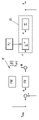
도 1은 본 발명에 따르는 가스 컨디셔닝을 갖는 연료 전지에 대한 시험대를 도시한다.
도 2는 연결된 다변수 시스템의 입력 변수를 변경하는 경우 시간에 따른 출력 변수의 곡선을 도시한다.
도 3은 가스 컨디셔닝을 위한 2 자유도를 갖는 본 발명에 따르는 제어기를 도시한다.
도 4는 본 발명에 따르는 분리된 다변수 시스템에서 입력 변수를 변경하는 경우에서 시간에 따른 출력 변수의 곡선을 도시한다. BRIEF DESCRIPTION OF THE DRAWINGS The invention will be described in more detail below with reference to, for example, schematically and without limitation, FIGS. 1 to 4 , which show preferred embodiments of the invention.
1 shows a test bench for a fuel cell with gas conditioning according to the present invention.
Figure 2 shows the curve of the output variable over time when changing the input variable of the connected multivariate system.
3 shows a controller according to the invention with two degrees of freedom for gas conditioning;
Fig. 4 shows the curve of the output variable over time in the case of changing the input variable in a separate multivariate system according to the present invention.
본 발명은 이하에서 도 1을 참조하여 양성자 교환막 연료 전지(PEMFC)(2)에 대한 시험대(1)의 예시를 기초로 일반화의 제한 없이 상세히 설명될 것이다. 물론, 연료 전지(2)가 또한 기계 또는 시설의 전기 공급기로서 사용될 수 있다. 그 후 이 기계 또는 시설에서 이러한 목적으로 가스 컨디셔닝 및 제어가 구현될 것이다. 이하에서 연료 전기(2)의 동작이 언급될 때, 이는 항상 시험대(1) 상에서의 연료 전지(2)의 동작 및 기계 또는 시설 내 연료 전지(2)의 실제 동작으로서 이해된다.The present invention will hereinafter be described in detail without limitation of generalization on the basis of an example of a
도 1에 따르는 예시에서 연료 전지(2)는 시험대(1) 상에 배열되고 시험대(1) 상에서 동작된다. 충분히 알려진 바와 같이, 연료 전지(2)는 제1 반응 가스, 가령, 산소가 공기의 형태로 공급되는 캐소드(C), 및 제2 반응 가스, 가령, 수소 H2가 공급되는 애노드(A)를 포함한다. 연료 전지(2)의 내부에서 2개의 반응 가스는 폴리머 막에 의해 서로 분리된다. 캐소드(C)와 애노드(A) 사이에서 전기 전압 U이 탭될 수 있다. 연료 전지(2)의 이 기본적인 구조 및 기능이 잘 알려져 있으며, 때문에 이들은 본 명세서에서 더 상세히 기재되지 않을 것이다. In the example according to FIG. 1 the
적어도 하나의 반응 가스, 일반적으로 산소 공급 반응 가스, 특히, 공기가 가스 컨디셔닝 유닛(3)에서 컨디셔닝된다. 가스 컨디셔닝 유닛(3)에서, 컨디셔닝된 반응 가스의 압력 p, 상대 습도 ![]()
![]()
![]()
![]()
대응하는 액추에이터가 이들 영향 변수를 제어하기 위해 가스 컨디셔닝 유닛(3)에 제공된다. 구체적으로, 반응 가스를 가습하여 반응 가스의 상대 습도 ![]()
![]()
![]()
![]()
가스 공급원(8)은 예를 들어 압축된 건식 반응 가스, 가령, 공기를 갖는 압력 저장소(pressure reservoir)이다. 대안으로, 공기가 사용되는 경우, 대기 공기가 또한 가스 공급원(8)으로서 처리, 가령, 필터링, 압축, 건조 등이 될 수 있다.The
온도 제어 유닛(5)은 예를 들어, 전기 가열 및 냉각 유닛 또는 열교환기이다. AT 516 385 A1에 기재된 유닛이 또한 온도 제어 유닛으로서 사용될 수 있다. The
이 예시적 실시예에서 가습기 유닛(4)은 수증기 발생기(9), 수증기에 대한 질량 유량 제어기(10), 및 혼합 챔버(11)를 포함한다. 종래의, 적절한, 상업적으로 이용 가능한, 제어 가능한 질량 유량 제어기가 수증기에 대한 질량 유량 제어기(10)로서 사용될 수 있고 또한 반응 가스에 대한 질량 유량 제어 유닛(6)으로서 사용될 수 있다. 수증기는 혼합 챔버(11)에서 가스 공급원(8)으로부터 기원하는 가스와 혼합되어 연료 전지(2)에 대한 컨디셔닝된 가스를 형성할 수 있다. The
물론, 가습기 유닛(4)의 그 밖의 다른 실시예가 또한 생각되어질 수 있다. 예를 들어, 물이 가스 공급원(8)으로부터의 가스로 공급, 가령, 주입될 수 있다.Of course, other embodiments of the
이 예시에서, 제어 가능한 오프닝 단면을 통해 반응 가스의 압력 p를 설정하는 카운터 압력 밸브가 압력 제어 유닛(7)으로서 사용된다. 카운터 압력 밸브(7)는 연료 전지(2)의 하류에 가스 컨디셔닝 유닛(3) 내에 배열된다. 이로써 압력이 연료 전지(2)의 상류에서 제어될 수 있고, 이로써, 압력 제어가 가스 컨디셔닝 유닛(3)의 다른 구성요소에서 가능한 압력 손실에 의해 영향 받지 않는 채 남아진다. In this example, a counter pressure valve which sets the pressure p of the reactant gas through the controllable opening cross-section is used as the
혼합 챔버(11) 후에, 반응 가스가 연료 전지(2)에 연결되거나, 더 정밀하게, 연료 전지(2)의 캐소드(C) 또는 애노드(A)에 연결된 반응 가스 라인(12)에서 비 온도 T, 비 상대 습도 ![]()
![]()
![]()
![]()
그러나 도 1을 토대로 기재된 가스 컨디셔닝 유닛(3)의 이 구조는 예시에 불과하며 물론 가스 컨디셔닝 유닛(3)의 또 다른 구조 및 가습기 유닛(4), 질량 유량 제어 유닛(6), 온도 제어 유닛(5) 및 온도 제어 유닛(7)의 그 밖의 다른 특정 실시예가 또한 생각되어질 수 있다.However, this structure of the
영향 변수를 제어할 수 있기 위해, 가습기 유닛(4), 질량 유량 제어 유닛(6), 온도 제어 유닛(5), 및 압력 제어 유닛(7)이 각자의 조작 변수를 통해 제어 가능하다. 조작 변수는 제어 유닛(15)에 의해 계산되며, 여기서 제어기(R)가 구현된다. 도 1에 도시된 실시예에서, 가습기 유닛(4)이 조작 변수 uS를 이용해 수증기에 대한 질량 유량 제어기(10)를 통해 제어되고, 질량 유량 제어 유닛(6)이 조작 변수 uG를 이용해 제어되고, 온도 제어 유닛(5)이 조작 변수 ![]()
![]()
먼저, 가스 컨디셔닝 유닛(3)의 모델이 가스 컨디셔닝 유닛(3)을 제어하기 위한 제어기(R)의 제어기 설계에 대해 요구된다. 이러한 목적을 위해 크게 변하는 모델이 또한 고려될 수 있다. 한 가지 바람직한 모델이 이하에서 기재될 것이며, 여기서 모든 4개의 영향 변수가 고려된다. 이를 위해, 우선 도 1에 따르는 구조물에 대한 시스템 수식이 전개된다. First, a model of the
혼합 챔버(11) 내 물질 균형(mass balance)에서,In the mass balance in the mixing

을 따르고, 이때, 가스의 질량이 mG, 혼합 챔버(11)로 들어가는 가스의 질량 유량이 ![]()
![]()
![]()
![]()
![]()
![]()
![]()
![]()
혼합 챔버(11) 밖으로 나가는 가스 및 수증기의 질량 유량은 The mass flow rate of gas and water vapor exiting the mixing
![]()
![]()
![]()
![]()
와 같이 주어지며, 이때, 가스 컨디셔닝 유닛(3) 내 총 질량이 m이고, 가스의 질량 mG이고 수증기의 질량이 mS이며 반응 가스의 질량 유량이 ![]()
![]()
가스 컨디셔닝 유닛(3)의 에너지 균형에서,In the energy balance of the gas conditioning unit (3),

를 따른다. follow
이 경우, U는 내부 에너지를 나타내고 h는 혼합 챔버(11) 후의 가스(본 명세서에서 인덱스 G로 마킹됨), 수증기(본 명세서에서 인덱스 S로 나타남), 및 반응 가스(본 명세서에서 인덱스 없이 나타남)의 비엔탈피(specific enthalpy)를 나타내며, ui는 가스 및 수증기의 비 내부 에너지를 나타낸다. 가스의 비엔탈피 h는 등압력에서의 비열용량 cp와 가스의 온도 T의 곱으로 알려져 있다. 수증기의 경우, 잠열 r0이 덧셈에 의해 추가된다. 가스의 내부 에너지 ui가 등체적에서의 비열용량 cv와 가스의 온도 T의 곱이다. 수증기의 경우, 잠열 r0이 또한 덧셈에 의해 포함된다. 이들 모두 에너지 균형에 삽입되고 질량 균형을 고려한다면, 가스 컨디셔닝 유닛(3)의 온도 동역학을 기술하는 다음의 시스템 수식이 획득된다: In this case, U represents the internal energy and h is the gas after mixing chamber 11 (marked herein as index G), water vapor (represented herein as index S), and reactant gas (represented herein without index) ) represents the specific enthalpy, and u i represents the specific internal energy of gas and water vapor. The specific enthalpy h of a gas is known as the product of the specific heat capacity c p at isopressure and the temperature T of the gas. For water vapor, the latent heat r 0 is added by addition. The internal energy u i of a gas is the product of the specific heat capacity c v in isovolume and the temperature T of the gas. For water vapor, the latent heat r 0 is also included by addition. If all of these are inserted into the energy balance and the mass balance is taken into account, the following system equation describing the temperature dynamics of the

또한, 이상적인 가스에 대한 열역학 상태 수식으로부터Also, from the thermodynamic state equation for an ideal gas,
![]()
![]()
를 따르고, 이때 연료 전지(2)의 인렛(inlet)에서의 압력이 p이고 온도가 T이다. R은 가스에 대한 기체 상수(인덱스 G), 수증기에 대한 기체 상수(인덱스 R), 또는 반응 가스에 대한 기체 상수(인덱스 없음)를 나타낸다. 체적 V는 이 경우에서 혼합 챔버(11)의 체적뿐 아니라, 가스 컨디셔닝 유닛(3) 내 파이프의 체적까지 나타내는 것이 바람직하다. 반응 가스의 압력 p 및 질량 유량 ![]()
![]()

와 같이 모델링될 수 있다. can be modeled as
여기서, A는 카운터 압력 밸브(7)의 오프닝 단면을 나타내며 p0는 대기압을 나타낸다.Here, A represents the opening cross-section of the
상대 습도 ![]()
![]()

에 의해 모델링되며, 여기서 pW(T)는, 예를 들어 ![]()
![]()
또한, 액추에이터의 동역학은 또한 시간 상수 ![]()
![]()
![]()
![]()

상기 수식에서 TG,0 및 A0는 지정 오프셋 변수이다.In the above formula, T G,0 and A 0 are designated offset variables.
상기 시스템 수식으로부터, From the above system formula,

형태의 비선형 다변수 시스템(MIMO, 복수 입력 복수 출력)가 제공되며, 상태 벡터 x, 입력 벡터 u, 및 출력 벡터 y가 다음과 같다:A nonlinear multivariate system (MIMO, multiple inputs multiple outputs) of the form is provided, where the state vector x, the input vector u, and the output vector y are:

도 1에서, 더 나은 이해를 위해, 이들 변수 각각이 발생하는 곳이 지시된다.In Figure 1, for a better understanding, where each of these variables occurs is indicated.
비선형성이 상태 수식으로부터 시스템 함수 f(x), g(x)로부터 도출되고, 출력 수식으로부터 시스템 함수 h(x)로부터 도출되며, 이들 각각이 상태 벡터 x에 종속적이다.Nonlinearities are derived from the system functions f(x), g(x) from the state equation, and from the system function h(x) from the output equation, each of which is dependent on the state vector x.
그러나, 가스 컨디셔닝 유닛(3)의 모델은 비선형일뿐 아니라 개별 상태 수식들이 또한 복수 번 연결됨으로써, 입력 벡터 u의 조작 변수 uS, uG, ![]()
![]()
![]()
![]()
![]()
![]()
![]()
![]()
도 2에서, 우측에서 조작 변수 uS, uG, ![]()
![]()
![]()
![]()
![]()
![]()
![]()
![]()
이제, 연결된 비선형 MIMO 시스템에 대해, 가스 컨디셔닝 유닛(3)이 제어될 수 있도록 하는 제어기가 설계되어야 한다. 이러한 목적으로 많은 옵션이 있고, 여기서 한 가지 바람직한 제어기 설계가 이하에서 기재될 것이다. Now, for the connected non-linear MIMO system, a controller must be designed that allows the
제1 단계로서, 비선형, 연결 다변수 시스템As a first step, a nonlinear, connected multivariate system

이 분리되고 선형화된다. 이러한 목적으로, 출력, 즉, 출력 변수 yi가 형태 ![]()
![]()

가 도출된다. 따라서 Lfh 및 Lgh가 연결된 비선형 다변수 시스템의 상태 수식의 시스템 함수 f(x) 및 g(x)에 관한 출력 수식의 시스템 함수 h(x)의 알려진 리 미분을 나타낸다. 따라서 리 미분 Lf 및 Lg가 

상기로부터, ![]()
![]()

여기서, ![]()
![]()

가 얻어지고, 여기서 분리 행렬이 J(x)이다. 출력 변수 y의 시간에 대한 δj차 도함수를 포함하는 벡터가 새로운 합성 입력 벡터, 즉is obtained, where the separation matrix is J(x). The vector containing the δ j derivative with respect to time of the output variable y is a new composite input vector, i.e.
![]()
![]()
가 된다. becomes
따라서 ![]()
![]()
이제 새 상태 벡터 z가 역시, 형태Now the new state vector z is also of the form

로 정의된다면, 새 다변수 시스템이 If defined as , the new multivariate system is
![]()
![]()
에 따라 선형, 비연결 상태 공간 모델로서 획득되며, is obtained as a linear, unconnected state space model according to
이때, 

또한 (δj × δj) 행렬이 

그 후 임의의 선형 제어 이론이 형태 ![]()
![]()
제어를 위해, 설정된 출력 변수 yj가 지정된 설정값 변수를 가능한 따르는 것(궤적 추적)이 바람직한 목표이다. 제어는 간섭에 가능한 내성이 있을 것이다. 이를 위해, 예를 들면, 피드포워드 제어기 FW와 피드백 제어기 FB로 구성된 2 자유도를 갖는 알려진 제어기 R(2DoF(Two-Degree-of-Freedom) 제어기)가 제안되고 도 3에 예시로서 나타난다. 피드포워드 제어기 FW는 궤적 추적을 보장하기 위한 것이고 피드백 제어기 FB는 가능한 간섭의 교정을 보장하기 위한 것이다.For control, it is a desirable goal that the set output variable y j follows the specified setpoint variable as much as possible (trajectory tracking). The control will be as tolerant of interference as possible. For this purpose, a known controller R (Two-Degree-of-Freedom (2DoF) controller) with two degrees of freedom consisting, for example, of a feedforward controller FW and a feedback controller FB is proposed and shown as an example in FIG. 3 . The feedforward controller FW is to ensure trajectory tracking and the feedback controller FB is to ensure correction of possible interference.
분리된, 선형 다변수 시스템(20)의 새로운 입력 변수 vj가 출력 변수 yj의 δj차 도함수에 대응한다. 따라서 제어기 R의 피드포워드 부분이 설정값 변수 yj,dmd의 δj차 도함수로서 도출된다. 설정값 변수 벡터 ydmd의 각각의 설정값 변수 yj,dmd가 자신의 상대 차수에 따라 얻어지고 피드백 제어기 FB의 출력에 추가로 연결된다.The new input variable v j of the isolated, linear
피드백 제어기 FB가 제어 에러 벡터 e를 알려진 방식으로, 설정값 변수 벡터 ydmd의 설정값 변수 yj,dmd와 출력 변수 y의 현재 실제 값 간 도함수, 즉, ej(t) = yj(t) - yj,dmd(t)로서 수신한다. 원칙적으로, 에러를 교정하는 데 어떠한 임의의 피드백 제어기도 사용될 수 있고 충분한 방법이 이러한 제어기를 결정하는 데 알려져있다. 단순한 피드백 제어기 FB가 이하에서 기재될 것이다. The feedback controller FB calculates the control error vector e in a known way, the derivative between the setpoint variable y j,dmd of the setpoint variable vector y dmd and the present actual value of the output variable y, i.e. e j (t) = y j (t ) - y receive as j,dmd (t). In principle, any arbitrary feedback controller can be used to correct the error and sufficient methods are known for determining such a controller. A simple feedback controller FB will be described below.
피드백 제어기 FB는 상대 차수 δj를 기초로 하고 다음의 에러 부분 ![]()
![]()
![]()
![]()
따라서 도 3에 따르는 분리된, 선형 다변수 시스템(20)의 새로운 입력 변수가 Thus, the new input variable of the isolated, linear
![]()
![]()
와 같이 써질 수 있다.can be written as
2의 상대 차수 δj에 대해, PID 제어기와의 유사성이 확립될 수 있고, 이때 Kj,0가 적분 성분을 형성하고, Kj,1가 비례 성분을 형성하며, Kj,2가 미분 성분을 형성한다. 1의 상대 차수 δj에 대해, PI 제어기가 도출될 것이다.For a relative order δ j of 2, a similarity with the PID controller can be established, where K j,0 forms the integral component, K j,1 forms the proportional component, and K j,2 the differential component to form For a relative order δ j of 1, the PI controller will be derived.
이는 다음과 같은 벡터 표현을 도출한다:This leads to the vector representation:
![]()
![]()
이때, 앞서 정의된 행렬 Ac, Bc, 및 
![]()
![]()
그 후 피드백 제어기 FB의 제어기 파라미터 Kj가 원하는 제어 거동을 획득하도록 정의될 수 있다. 또한 이러한 목적으로, 다양한 알려진 접근법이 존재하는데, 가령, ![]()
![]()
도 3에서 Σ-1로 특징지어지는 비선형, 연결된 다변수 시스템의 앞서 기재된 선형화 및 분리를 위해, 수학식으로부터 자명하듯이 그리고 도 3에서 지시되듯이, 상태 변수 x가 또한 필요하다. For the previously described linearization and decoupling of the nonlinear, coupled multivariate system characterized by Σ −1 in FIG. 3 , as is evident from the equation and indicated in FIG. 3 , the state variable x is also needed.
이를 위해, 상태 변수 x가 가스 컨디셔닝 유닛(3)에서, 바람직하게는, 제어기의 매 샘플링 시마다, 측정될 수 있다. 대안으로, 입력 변수 u 및/또는 출력 변수 y로부터 관측자(observer)에 의해, 바람직하게는 제어의 매 샘플링 시마다, 상태 변수 x가 또한 추정될 수 있다. 그러나 상태 변수 x가 또한 또 다른 단순한 방식으로 계산될 수 있다. To this end, the state variable x can be measured in the
미분 독립적 출력 변수의 벡터 y=(y1,…,ym)가 존재하는 경우 일반 형태 ![]()
![]()

따라서, 출력 변수 y(t)의 임의의 시간 곡선에 대해, 다변수 시스템의 미분 수식을 적분하지 않고, 입력 변수 u(t)의 연관된 시간 곡선 및 상태 변수 x(t)의 시간 곡선이 오로지 출력 변수 y(t)의 시간 곡선으로부터 계산될 수 있다. Thus, for any time curve of the output variable y(t), without integrating the differential equation of the multivariate system, the associated time curve of the input variable u(t) and the time curve of the state variable x(t) are only output It can be calculated from the time curve of the variable y(t).
상기에서 기재된 비선형 다변수 시스템은 미분적으로 평탄함을 알 수 있다. 따라서 상태 변수 x가 간단히 설정값 변수 ydmd의 시간 곡선으로부터 계산될 수 있으며 측정되거나 추정될 필요가 없다. 이는 도 3에서 상태 변수 x의 인덱스 F로 지시된다. 시험대(1)에서, 예를 들어, 실행될 시험에 의해 설정값 변수 ydmd의 시간 곡선이 정의되고 따라서 알려진다. 따라서 상태 변수 xF는 미리 오프라인으로 설정값 변수 ydmd의 시간 곡선으로부터 계산될 수 있고 그 후 테스트가 실행될 때 제어를 위해 이용 가능할 수 있다.It can be seen that the nonlinear multivariate system described above is differentially flat. Thus, the state variable x can simply be calculated from the time curve of the setpoint variable y dmd and need not be measured or estimated. This is indicated by the index F of the state variable x in FIG. 3 . On the
본 명세서에 기재된 절차가 연료 전지(2)의 동작을 위한 가스 컨디셔닝 유닛(3)의 제어를 위해 사용될 수 있다. The procedure described herein can be used for control of the
우선, 필요에 따라, 우수한 궤적 추적을 가지며 안정적이고 강건한, 즉, 간섭에 실질적으로 비민감성인 제어기 R가 앞서 기재된 바와 같이 설계된다. 이는 예를 들어, 피드백 제어기 FB의 극의 선택에 의해 달성된다. 그러나 이미 파라미터화된 제어기 R가 또한 사용될 수 있다. 연료 전지(2)의 동작을 위해, 설정값 변수로서 사용되는 출력 변수 T, p, ![]()
![]()
![]()
![]()
시간의 흐름에 따른 지정 설정값 변수 곡선 ydmd(t)의 형태로 된 이러한 시험 실행이 시뮬레이션되었고 결과가 도 4에 도시되어 있다. 다음의 파라미터가 시뮬레이션을 위해 가정되었다: 가습기 유닛의 조정 범위 4us=[0-30 kgh-1], 온도 제어 유닛의 조정 범위 5 ![]()
![]()
![]()
![]()
![]()
![]()
시간의 흐름에 따른 지정 설정값 변수 곡선 ydmd(t)이 도 4 내 좌측에 도시되어 있다. 제어기 R에 의해 설정되는 입력 변수 u가 우측에 도시되어 있다. 시뮬레이션에서 계산된 출력 변수 y가 또한 좌측 다이어그램에 도시되어 있다. 한편, 제어기의 눈에 띄는 궤적 추적이 나타날 수 있는데, 즉, 출력 변수 y가 인식 가능한 편차 없이 설정값 변수 ydmd를 따른다. 그러나 다른 한편으로 여기서 개별 출력 변수 yj가 서로 분리되어 설정될 수 있음이 또한 자명하다. 한 출력 변수 yj의 변경이 다른 출력 변수를 본래 그대로 남겨둔다. 이를 위해, 제어기 R는 모든 샘플링 시간마다 새로운 입력 변수 v의 조합을 계산하며, 이는 가스 컨디셔닝 유닛(3)의 액추에이터를 이용하여 설정될 필요가 있는 입력 변수 u를 도출한다. A curve of the setpoint variable over time y dmd (t) is shown on the left in FIG. 4 . The input variable u set by the controller R is shown on the right. The output variable y calculated in the simulation is also shown in the diagram on the left. On the other hand, a conspicuous trajectory trace of the controller may appear, ie the output variable y follows the setpoint variable y dmd with no discernible deviation. But on the other hand, it is also self-evident here that the individual output variables y j can be set separately from each other. A change in one output variable y j leaves the other output variable intact. To this end, the controller R calculates a new combination of input variables v at every sampling time, which derives the input variable u which needs to be set using the actuator of the
본 발명은 모든 4개의 영향 변수 또는 출력 변수 yj, 즉, 온도 T, 압력 p, 상대 습도 ![]()
![]()
![]()
![]()
연료 전지(2)의 반응 가스의 가스 컨디셔닝을 위한 제어된 가스 컨디셔닝 유닛(3)의 응용예가 다기관이다. 가스 컨디셔닝은 특히 시험대(스택 또는 셀 시험대)에서 사용될 수 있고 또한 차량(배, 열차, 비행기, 승용차, 트럭, 자전거, 모터사이클 등), 발전소(조합된 열과 전력 시스템), 응급 전력 시스템, 핸드헬드 디바이스, 연료 전지 시스템이 설치될 수 있는 임의의 디바이스 내 연료 전지 시스템에서 사용될 수 있다. 따라서 가스 컨디셔닝은 연료 전지 시스템 내 연료 전지의 실제 동작에서뿐 아니라 연료 전지를 시험하거나 개발하기 위한 시험대에서도 사용될 수 있다. An example of application of a controlled
가스 컨디셔닝은 기본적으로 그 밖의 다른 경우에 예를 들어, 내연 기관의 흡기 공기(intake air)의 컨디셔닝을 위해 실제 동작에서나 시험대에서 적용 가능하다. 그러나 또한 공정 기술 또는 의료 기술에서의 가스가 이에 따라 컨디셔닝될 수 있다. 정확한 측정치를 위해 측정 가스를 정확히 컨디셔닝하기 위해 가스 컨디션이 또한 측정 기술에서 사용될 수 있다.Gas conditioning is basically applicable in practical operation or on the test bench in other cases, for example for conditioning the intake air of an internal combustion engine. But also gases in process technology or medical technology can be conditioned accordingly. Gas conditions can also be used in measurement techniques to precisely condition the measurement gas for accurate measurements.
Claims (7)
연료 전지(2)의 반응 가스에 대한 가스 공급원(8), 반응 가스의 상대 습도(
가습기 유닛(4), 온도 제어 유닛(5), 질량 유량 제어 유닛(6), 및 압력 제어 유닛(7)의 그룹 중 적어도 3개의 액추에이터에 대해 조작 변수 (uG, uS, uN,

The gas supply source 8 for the reaction gas of the fuel cell 2, the relative humidity of the reaction gas (
the operating variables (uG, uS, uN, uG, uS, uN,
연결된, 비선형 다변수 시스템의 형태

Forms of connected, nonlinear multivariate systems


Applications Claiming Priority (3)
| Application Number | Priority Date | Filing Date | Title |
|---|---|---|---|
| ATA50663/2016A AT518518B1 (en) | 2016-07-20 | 2016-07-20 | Controlled gas conditioning for a reaction gas of a fuel cell |
| ATA50663/2016 | 2016-07-20 | ||
| PCT/EP2017/067999 WO2018015336A1 (en) | 2016-07-20 | 2017-07-17 | Regulated gas conditioning process for a reaction gas of a fuel cell |
Publications (2)
| Publication Number | Publication Date |
|---|---|
| KR20190030736A KR20190030736A (en) | 2019-03-22 |
| KR102408594B1 true KR102408594B1 (en) | 2022-06-13 |
Family
ID=59388068
Family Applications (1)
| Application Number | Title | Priority Date | Filing Date |
|---|---|---|---|
| KR1020197004915A KR102408594B1 (en) | 2016-07-20 | 2017-07-17 | Controlled Gas Conditioning for Reactant Gases in Fuel Cells |
Country Status (8)
| Country | Link |
|---|---|
| US (1) | US10714766B2 (en) |
| EP (1) | EP3488480A1 (en) |
| JP (1) | JP6943943B2 (en) |
| KR (1) | KR102408594B1 (en) |
| CN (1) | CN109690850B (en) |
| AT (1) | AT518518B1 (en) |
| CA (1) | CA3031405A1 (en) |
| WO (1) | WO2018015336A1 (en) |
Families Citing this family (8)
| Publication number | Priority date | Publication date | Assignee | Title |
|---|---|---|---|---|
| AT520522B1 (en) | 2017-12-05 | 2019-05-15 | Avl List Gmbh | Control of a controlled variable of a conditioning unit of a reactant of a fuel cell with determination of an actual value of the controlled variable |
| FR3092364B1 (en) * | 2019-02-04 | 2021-01-01 | Cpt Group | Method of injecting ammonia in gaseous form into a heat engine exhaust line |
| CN111079337B (en) * | 2019-12-23 | 2023-09-01 | 畔星科技(浙江)有限公司 | Multi-physical field coupling simulation method for proton exchange membrane fuel cell |
| CN111952646A (en) * | 2020-07-13 | 2020-11-17 | 重庆地大工业技术研究院有限公司 | Decoupling control method and system for fuel cell air system |
| CN112364544B (en) * | 2020-11-19 | 2022-04-12 | 中国空气动力研究与发展中心超高速空气动力研究所 | Finite element solving and optimizing method for structure-induced thermal response caused by reentry of pneumatic environment |
| CN113140765A (en) * | 2021-03-04 | 2021-07-20 | 同济大学 | Fuel cell air inlet flow and pressure decoupling control method and system |
| CN113050423B (en) * | 2021-03-18 | 2022-06-24 | 绍兴学森能源科技有限公司 | Self-adaptive decoupling control method of fuel cell air supply system |
| CN114021454B (en) * | 2021-11-03 | 2022-10-21 | 国网山东省电力公司营销服务中心(计量中心) | Electric energy meter comprehensive verification test error decoupling method and system |
Citations (1)
| Publication number | Priority date | Publication date | Assignee | Title |
|---|---|---|---|---|
| JP2002372262A (en) * | 2001-06-15 | 2002-12-26 | Sanki Eng Co Ltd | Gas supply system and test system |
Family Cites Families (20)
| Publication number | Priority date | Publication date | Assignee | Title |
|---|---|---|---|---|
| WO2004049479A2 (en) * | 2002-11-27 | 2004-06-10 | Hydrogenics Corporation | An electrolyzer module for producing hydrogen for use in a fuel cell power unit |
| DE102004002142A1 (en) | 2004-01-15 | 2005-08-11 | Robert Bosch Gmbh | Method and computer program for generating a model for the behavior of a control device |
| WO2005119824A2 (en) * | 2004-05-28 | 2005-12-15 | Idatech, Llc | Utilization-based fuel cell monitoring and control |
| US7526346B2 (en) * | 2004-12-10 | 2009-04-28 | General Motors Corporation | Nonlinear thermal control of a PEM fuel cell stack |
| US7838138B2 (en) * | 2005-09-19 | 2010-11-23 | 3M Innovative Properties Company | Fuel cell electrolyte membrane with basic polymer |
| US7829234B2 (en) * | 2005-12-15 | 2010-11-09 | Gm Global Technology Operations, Inc. | Non-linear cathode inlet/outlet humidity control |
| JP2007220538A (en) * | 2006-02-17 | 2007-08-30 | Nissan Motor Co Ltd | Fuel cell system |
| WO2007126308A1 (en) | 2006-05-01 | 2007-11-08 | Heselmans Johannes Jacobus Mar | Applications for sacrificial anodes |
| US7517600B2 (en) * | 2006-06-01 | 2009-04-14 | Gm Global Technology Operations, Inc. | Multiple pressure regime control to minimize RH excursions during transients |
| CN100545584C (en) * | 2006-08-10 | 2009-09-30 | 上海神力科技有限公司 | Be applied to the humidity temperature pickup of fuel cell |
| CN101165506A (en) * | 2006-10-17 | 2008-04-23 | 上海博能同科燃料电池系统有限公司 | Fuel battery test system based on network study control |
| US8173311B2 (en) * | 2007-02-26 | 2012-05-08 | GM Global Technology Operations LLC | Method for dynamic adaptive relative humidity control in the cathode of a fuel cell stack |
| DE102007014616A1 (en) * | 2007-03-23 | 2008-09-25 | Forschungszentrum Jülich GmbH | Fuel cell system and method for controlling a fuel cell system |
| DE102008024513B4 (en) * | 2008-05-21 | 2017-08-24 | Liebherr-Werk Nenzing Gmbh | Crane control with active coast sequence |
| US8810221B2 (en) * | 2009-06-18 | 2014-08-19 | The Board Of Regents, The University Of Texas System | System, method and apparatus for controlling converters using input-output linearization |
| CN102754264A (en) * | 2011-01-28 | 2012-10-24 | 丰田自动车株式会社 | Fuel cell system |
| DE102012218636A1 (en) * | 2012-10-12 | 2014-04-17 | Robert Bosch Gmbh | Determination of the fuel cell input humidity via pressure sensors and a mass flow-dependent control of the humidifier bypass |
| CN102968056A (en) * | 2012-12-07 | 2013-03-13 | 上海电机学院 | Modeling system of proton exchange membrane fuel cell (PEMFC) and intelligent predictive control method thereof |
| US10211470B2 (en) * | 2013-03-11 | 2019-02-19 | University Of Florida Research Foundation, Inc. | Operational control of fuel cells |
| CN105653827B (en) * | 2016-03-17 | 2020-03-13 | 北京工业大学 | Hypersonic aircraft Terminal sliding mode controller design method |
-
2016
- 2016-07-20 AT ATA50663/2016A patent/AT518518B1/en not_active IP Right Cessation
-
2017
- 2017-07-17 CA CA3031405A patent/CA3031405A1/en active Pending
- 2017-07-17 EP EP17743004.8A patent/EP3488480A1/en not_active Withdrawn
- 2017-07-17 JP JP2019502570A patent/JP6943943B2/en active Active
- 2017-07-17 CN CN201780044244.1A patent/CN109690850B/en active Active
- 2017-07-17 KR KR1020197004915A patent/KR102408594B1/en active IP Right Grant
- 2017-07-17 US US16/318,338 patent/US10714766B2/en active Active
- 2017-07-17 WO PCT/EP2017/067999 patent/WO2018015336A1/en unknown
Patent Citations (1)
| Publication number | Priority date | Publication date | Assignee | Title |
|---|---|---|---|---|
| JP2002372262A (en) * | 2001-06-15 | 2002-12-26 | Sanki Eng Co Ltd | Gas supply system and test system |
Also Published As
| Publication number | Publication date |
|---|---|
| US10714766B2 (en) | 2020-07-14 |
| JP6943943B2 (en) | 2021-10-06 |
| AT518518A4 (en) | 2017-11-15 |
| AT518518B1 (en) | 2017-11-15 |
| CN109690850A (en) | 2019-04-26 |
| KR20190030736A (en) | 2019-03-22 |
| EP3488480A1 (en) | 2019-05-29 |
| JP2019530129A (en) | 2019-10-17 |
| WO2018015336A1 (en) | 2018-01-25 |
| US20190245223A1 (en) | 2019-08-08 |
| CA3031405A1 (en) | 2018-01-25 |
| CN109690850B (en) | 2022-06-14 |
Similar Documents
| Publication | Publication Date | Title |
|---|---|---|
| KR102408594B1 (en) | Controlled Gas Conditioning for Reactant Gases in Fuel Cells | |
| Rabbani et al. | Effect of nitrogen crossover on purging strategy in PEM fuel cell systems | |
| Pukrushpan | Modeling and control of fuel cell systems and fuel processors | |
| del Real et al. | Development and experimental validation of a PEM fuel cell dynamic model | |
| Wu et al. | Fault tolerance control for proton exchange membrane fuel cell systems | |
| Wang et al. | Design and experimental implementation of time delay control for air supply in a polymer electrolyte membrane fuel cell system | |
| Karnik et al. | Humidity and pressure regulation in a PEM fuel cell using a gain-scheduled static feedback controller | |
| WO2019121132A1 (en) | Method and test bench for carrying out a test run for a fuel cell | |
| Jiao et al. | Humidity estimation of vehicle proton exchange membrane fuel cell under variable operating temperature based on adaptive sliding mode observation | |
| Lotfi et al. | Active disturbance rejection control for voltage stabilization in open-cathode fuel cells through temperature regulation | |
| Kancsár et al. | A novel approach for dynamic gas conditioning for PEMFC stack testing | |
| Barzegari et al. | Reduced-order model of cascade-type PEM fuel cell stack with integrated humidifiers and water separators | |
| Song et al. | AI-based proton exchange membrane fuel cell inlet relative humidity control | |
| Ebadighajari et al. | Multivariable control of hydrogen concentration and fuel over-pressure in a polymer electrolyte membrane fuel cell with anode re-circulation | |
| Chen et al. | Observer based fuel delivery control for PEM fuel cells with a segmented anode model | |
| Brandstätter et al. | Highly integrated fuel cell analysis infrastructure for advanced research topics | |
| Rigatos et al. | A PEM fuel cells control approach based on differential flatness theory | |
| Chen et al. | Analysis of non-minimum phase behavior of PEM fuel cell membrane humidification systems | |
| Di Domenico et al. | Multi-variable control for an automotive traction PEM fuel cell system | |
| CN111433956B (en) | Controlling a controlled variable of a control unit of a fuel cell reactant by determining an actual value of the controlled variable | |
| Olteanu et al. | Contribution to state and sensor fault estimation applied to PEM Fuel Cell Systems | |
| Pukrushpan | Modeling and control of PEM fuel cell systems and fuel processors | |
| Schitz et al. | Model-Based Nonlinear Control of the Cathode Pressure of a PEM Fuel Cell System Using a VTG | |
| Kancsár et al. | Flatness-based feedforward control of polymer electrolyte membrane fuel cell gas conditioning system | |
| Liu et al. | Sliding-Mode-Observer-Based Fault Diagnosis of PEMFC Systems |
Legal Events
| Date | Code | Title | Description |
|---|---|---|---|
| A201 | Request for examination | ||
| E902 | Notification of reason for refusal | ||
| E701 | Decision to grant or registration of patent right | ||
| GRNT | Written decision to grant |