KR102358218B1 - Merging units for single or multiple containers - Google Patents
Merging units for single or multiple containers Download PDFInfo
- Publication number
- KR102358218B1 KR102358218B1 KR1020187001386A KR20187001386A KR102358218B1 KR 102358218 B1 KR102358218 B1 KR 102358218B1 KR 1020187001386 A KR1020187001386 A KR 1020187001386A KR 20187001386 A KR20187001386 A KR 20187001386A KR 102358218 B1 KR102358218 B1 KR 102358218B1
- Authority
- KR
- South Korea
- Prior art keywords
- fluid
- merging device
- merging
- container
- connection assembly
- Prior art date
Links
Images


Classifications
-
- A—HUMAN NECESSITIES
- A61—MEDICAL OR VETERINARY SCIENCE; HYGIENE
- A61J—CONTAINERS SPECIALLY ADAPTED FOR MEDICAL OR PHARMACEUTICAL PURPOSES; DEVICES OR METHODS SPECIALLY ADAPTED FOR BRINGING PHARMACEUTICAL PRODUCTS INTO PARTICULAR PHYSICAL OR ADMINISTERING FORMS; DEVICES FOR ADMINISTERING FOOD OR MEDICINES ORALLY; BABY COMFORTERS; DEVICES FOR RECEIVING SPITTLE
- A61J1/00—Containers specially adapted for medical or pharmaceutical purposes
- A61J1/14—Details; Accessories therefor
- A61J1/20—Arrangements for transferring or mixing fluids, e.g. from vial to syringe
- A61J1/2089—Containers or vials which are to be joined to each other in order to mix their contents
-
- A—HUMAN NECESSITIES
- A61—MEDICAL OR VETERINARY SCIENCE; HYGIENE
- A61J—CONTAINERS SPECIALLY ADAPTED FOR MEDICAL OR PHARMACEUTICAL PURPOSES; DEVICES OR METHODS SPECIALLY ADAPTED FOR BRINGING PHARMACEUTICAL PRODUCTS INTO PARTICULAR PHYSICAL OR ADMINISTERING FORMS; DEVICES FOR ADMINISTERING FOOD OR MEDICINES ORALLY; BABY COMFORTERS; DEVICES FOR RECEIVING SPITTLE
- A61J1/00—Containers specially adapted for medical or pharmaceutical purposes
- A61J1/14—Details; Accessories therefor
- A61J1/20—Arrangements for transferring or mixing fluids, e.g. from vial to syringe
- A61J1/2003—Accessories used in combination with means for transfer or mixing of fluids, e.g. for activating fluid flow, separating fluids, filtering fluid or venting
- A61J1/2006—Piercing means
- A61J1/2013—Piercing means having two piercing ends
-
- A—HUMAN NECESSITIES
- A61—MEDICAL OR VETERINARY SCIENCE; HYGIENE
- A61J—CONTAINERS SPECIALLY ADAPTED FOR MEDICAL OR PHARMACEUTICAL PURPOSES; DEVICES OR METHODS SPECIALLY ADAPTED FOR BRINGING PHARMACEUTICAL PRODUCTS INTO PARTICULAR PHYSICAL OR ADMINISTERING FORMS; DEVICES FOR ADMINISTERING FOOD OR MEDICINES ORALLY; BABY COMFORTERS; DEVICES FOR RECEIVING SPITTLE
- A61J1/00—Containers specially adapted for medical or pharmaceutical purposes
- A61J1/14—Details; Accessories therefor
- A61J1/20—Arrangements for transferring or mixing fluids, e.g. from vial to syringe
- A61J1/2003—Accessories used in combination with means for transfer or mixing of fluids, e.g. for activating fluid flow, separating fluids, filtering fluid or venting
- A61J1/2048—Connecting means
- A61J1/2058—Connecting means having multiple connecting ports
- A61J1/2062—Connecting means having multiple connecting ports with directional valves
-
- A—HUMAN NECESSITIES
- A61—MEDICAL OR VETERINARY SCIENCE; HYGIENE
- A61M—DEVICES FOR INTRODUCING MEDIA INTO, OR ONTO, THE BODY; DEVICES FOR TRANSDUCING BODY MEDIA OR FOR TAKING MEDIA FROM THE BODY; DEVICES FOR PRODUCING OR ENDING SLEEP OR STUPOR
- A61M5/00—Devices for bringing media into the body in a subcutaneous, intra-vascular or intramuscular way; Accessories therefor, e.g. filling or cleaning devices, arm-rests
- A61M5/14—Infusion devices, e.g. infusing by gravity; Blood infusion; Accessories therefor
- A61M5/1407—Infusion of two or more substances
-
- A—HUMAN NECESSITIES
- A61—MEDICAL OR VETERINARY SCIENCE; HYGIENE
- A61J—CONTAINERS SPECIALLY ADAPTED FOR MEDICAL OR PHARMACEUTICAL PURPOSES; DEVICES OR METHODS SPECIALLY ADAPTED FOR BRINGING PHARMACEUTICAL PRODUCTS INTO PARTICULAR PHYSICAL OR ADMINISTERING FORMS; DEVICES FOR ADMINISTERING FOOD OR MEDICINES ORALLY; BABY COMFORTERS; DEVICES FOR RECEIVING SPITTLE
- A61J1/00—Containers specially adapted for medical or pharmaceutical purposes
- A61J1/05—Containers specially adapted for medical or pharmaceutical purposes for collecting, storing or administering blood, plasma or medical fluids ; Infusion or perfusion containers
- A61J1/06—Ampoules or carpules
-
- A—HUMAN NECESSITIES
- A61—MEDICAL OR VETERINARY SCIENCE; HYGIENE
- A61J—CONTAINERS SPECIALLY ADAPTED FOR MEDICAL OR PHARMACEUTICAL PURPOSES; DEVICES OR METHODS SPECIALLY ADAPTED FOR BRINGING PHARMACEUTICAL PRODUCTS INTO PARTICULAR PHYSICAL OR ADMINISTERING FORMS; DEVICES FOR ADMINISTERING FOOD OR MEDICINES ORALLY; BABY COMFORTERS; DEVICES FOR RECEIVING SPITTLE
- A61J1/00—Containers specially adapted for medical or pharmaceutical purposes
- A61J1/14—Details; Accessories therefor
- A61J1/20—Arrangements for transferring or mixing fluids, e.g. from vial to syringe
- A61J1/2003—Accessories used in combination with means for transfer or mixing of fluids, e.g. for activating fluid flow, separating fluids, filtering fluid or venting
- A61J1/2006—Piercing means
- A61J1/201—Piercing means having one piercing end
-
- A—HUMAN NECESSITIES
- A61—MEDICAL OR VETERINARY SCIENCE; HYGIENE
- A61J—CONTAINERS SPECIALLY ADAPTED FOR MEDICAL OR PHARMACEUTICAL PURPOSES; DEVICES OR METHODS SPECIALLY ADAPTED FOR BRINGING PHARMACEUTICAL PRODUCTS INTO PARTICULAR PHYSICAL OR ADMINISTERING FORMS; DEVICES FOR ADMINISTERING FOOD OR MEDICINES ORALLY; BABY COMFORTERS; DEVICES FOR RECEIVING SPITTLE
- A61J1/00—Containers specially adapted for medical or pharmaceutical purposes
- A61J1/14—Details; Accessories therefor
- A61J1/20—Arrangements for transferring or mixing fluids, e.g. from vial to syringe
- A61J1/2003—Accessories used in combination with means for transfer or mixing of fluids, e.g. for activating fluid flow, separating fluids, filtering fluid or venting
- A61J1/2079—Filtering means
- A61J1/2082—Filtering means for gas filtration
-
- A—HUMAN NECESSITIES
- A61—MEDICAL OR VETERINARY SCIENCE; HYGIENE
- A61M—DEVICES FOR INTRODUCING MEDIA INTO, OR ONTO, THE BODY; DEVICES FOR TRANSDUCING BODY MEDIA OR FOR TAKING MEDIA FROM THE BODY; DEVICES FOR PRODUCING OR ENDING SLEEP OR STUPOR
- A61M5/00—Devices for bringing media into the body in a subcutaneous, intra-vascular or intramuscular way; Accessories therefor, e.g. filling or cleaning devices, arm-rests
- A61M5/14—Infusion devices, e.g. infusing by gravity; Blood infusion; Accessories therefor
- A61M5/162—Needle sets, i.e. connections by puncture between reservoir and tube ; Connections between reservoir and tube
- A61M2005/1623—Details of air intake
-
- A—HUMAN NECESSITIES
- A61—MEDICAL OR VETERINARY SCIENCE; HYGIENE
- A61M—DEVICES FOR INTRODUCING MEDIA INTO, OR ONTO, THE BODY; DEVICES FOR TRANSDUCING BODY MEDIA OR FOR TAKING MEDIA FROM THE BODY; DEVICES FOR PRODUCING OR ENDING SLEEP OR STUPOR
- A61M39/00—Tubes, tube connectors, tube couplings, valves, access sites or the like, specially adapted for medical use
Abstract
적어도 하나의 용기(14, 16)를 갖는 용기 유닛(12)으로부터 유체를 병합하기 위한 장치(10)가 제공되고, 유체 또는 주위 공기를 받도록 구성된 적어도 하나의 입구 채널(22, 24)을 갖는 입구 포트(18), 및 유체를 부착부를 전달하도록 구성된 적어도 하나의 출구 채널(32, 34)을 갖는 출구 포트(26)를 포함한다. 입구 포트(18) 및 출구 포트(26) 모두는 장치(10) 상에 배치된다. 공동(40)이 적어도 하나의 용기(14, 16)로부터 유체를 병합하기 위해 용기 유닛(12)의 삽입을 수용하도록 제공된다. 적어도 하나의 스파이크(48, 50)가 공동 내에 배치되고, 용기 유닛이 상위 위치로부터 하위 위치로 전이할 때, 적어도 하나의 용기의 스토퍼(44, 46)를 천공하도록 구성된다.An apparatus (10) is provided for incorporating a fluid from a vessel unit (12) having at least one vessel (14, 16), the inlet having at least one inlet channel (22, 24) configured to receive fluid or ambient air an outlet port 26 having a port 18 and at least one outlet channel 32 , 34 configured to deliver a fluid to the attachment. Both inlet port 18 and outlet port 26 are disposed on device 10 . A cavity 40 is provided to accommodate the insertion of a container unit 12 to incorporate fluid from the at least one container 14 , 16 . At least one spike (48, 50) is disposed within the cavity and is configured to puncture the stopper (44, 46) of the at least one container when the container unit transitions from the upper position to the lower position.

Description
교차 참조cross reference
본 출원은 참조로 통합된, 35 U.S.C. § 119(e) 하에서 2015년 6월 19일자로 출원된 미국 가특허 출원 제62/182,099호에 기초하여 우선권을 주장한다.This application is incorporated by reference, 35 U.S.C. Priority is claimed under U.S. Provisional Patent Application No. 62/182,099, filed on June 19, 2015 under § 119(e).
본 개시내용은 의료용 목적으로 사용되는 병합 장치에 관한 것이고, 더 구체적으로 동시 사용을 위해 의약품 용기들로부터 내용물을 병합하도록 구성된 장치에 관한 것이다.The present disclosure relates to a merging device used for medical purposes, and more particularly to a device configured to merge contents from pharmaceutical containers for simultaneous use.
많은 경우에, 의약품 제제 또는 유체가 그들의 화학적 및 물리적 안정성을 위해 사용 이전에 분리되어 있다. 따라서, 유체들은 유체들이 환자에게 정맥으로 투여되도록 함께 혼합될 때까지 개별적으로 포장되어 보관된다. 전통적으로, 유체들의 혼합은 의료에 의해 제1 유체를 제2 유체를 갖는 유리 바이알 또는 용기 내로 주입함으로써 달성된다. 제1 유체와 제2 유체를 혼합한 후에, 혼합된 용액이 시린지 배럴 내로 취출되어, 환자 내로 정맥으로 주입된다. 소정의 경우에, 2개의 용액은 환자로의 전달 이전에, 정맥(IV) 투여 주머니 또는 세트와 같은 대형 용기 내에서 혼합되거나, 혼합된 용액이 대형 용기로 운반된다.In many cases, pharmaceutical formulations or fluids are separated prior to use for their chemical and physical stability. Accordingly, the fluids are individually packaged and stored until the fluids are mixed together for intravenous administration to the patient. Traditionally, mixing of fluids is accomplished by medically injecting a first fluid into a glass vial or container with a second fluid. After mixing the first fluid and the second fluid, the mixed solution is withdrawn into the syringe barrel and injected intravenously into the patient. In certain instances, the two solutions are mixed in a large container, such as an intravenous (IV) administration bag or set, prior to delivery to the patient, or the mixed solution is delivered to the large container.
몇몇 의약품 유체는 혼합이 없이 순차적으로 투여된다. 예를 들어, 제1 유체는 제2 유체가 환자에게 전달되거나 환자에 의해 처리되는 조건을 개선하기 위해 초기에 투여될 수 있다. 제1 유체 및 제2 유체를 투여하기 위한 예시적인 이중 의료용 용기 유닛이 참조로 통합된, 공동 양도된 미국 특허 제8,684,433호에 설명되어 있다. 소정의 경우에, 의약품 유체의 여러 바이알이 환자에게 올바른 용량을 제공하기 위해 조합되어야 한다. 소정의 면역결핍 질환을 앓는 환자는 상대적으로 큰 체적의 면역글로불린(IG) 유체의 투입에 의해 치료된다. 제1 유체 의약품이 제2 의약품인 상대적으로 높은 점성의 IG 유체에 대한 신체 수용을 향상시키기 위해 적용된다. 종래에, 유체를 투여하는 의료진은 유체의 종별 및 농도를 확인하고, 알코올과 같은 소독제를 사용하여 각각의 용기의 대응하는 스토퍼를 닦고, 유체의 전달을 위해 각각의 용기의 스토퍼를 뚫고, 복수의 시린지 및 병합 주머니를 사용하여 각각의 용기로부터의 분리된 유체들을 병합하고, 그 다음 이어서 환자에 대한 유체의 투여를 수행한다. 소정의 경우에, 이중 용기 유닛은 유체들 중 하나 이상이 중력 유동에 의해 병합 주머니로 전달되도록 손으로 상승되거나 IV 기둥에 매달린다.Some pharmaceutical fluids are administered sequentially without mixing. For example, a first fluid may be initially administered to improve the condition in which a second fluid is delivered to or treated by the patient. An exemplary dual medical container unit for administering a first fluid and a second fluid is described in commonly assigned US Pat. No. 8,684,433, incorporated by reference. In certain cases, several vials of pharmaceutical fluid must be combined to provide the correct dose to the patient. Patients with certain immunodeficiency disorders are treated by infusion of relatively large volumes of immunoglobulin (IG) fluid. The first fluid drug product is applied to enhance the body's acceptance of the relatively high viscosity IG fluid as the second drug product. Conventionally, a medical staff administering a fluid confirms the type and concentration of the fluid, wipes the corresponding stopper of each container using a disinfectant such as alcohol, pierces the stopper of each container for delivery of the fluid, a plurality of A syringe and merging bag are used to merge the separated fluids from each container, followed by administration of the fluid to the patient. In some cases, the dual container unit is raised by hand or suspended from an IV post such that one or more of the fluids are delivered by gravity flow to the merging bag.
몇몇 경우에, 대안적으로 가정에서 환자에 의해 수행되는 이러한 다단계 공정으로 인해, 종래의 투여 방법은 오조작 및 실수의 경향이 있다. 예를 들어, 병, 바이알, 또는 다른 용기가 오조작될 수 있고, 심지어 결국 손상되거나 파손될 수 있다. 아울러, 여러 수동 단계들이 멸균 환경 내에서 투여의 원하는 시퀀스를 달성하기 위해 현재 필요하고, 상당한 양의 시간이 많은 수동 단계로 인해 소비되고, 상당한 공간이 사용 중에 장비의 재고를 보관하기 위해 요구된다. 의약품 유체의 멸균 투여가 훼손될 수 있으면, 박테리아 또는 환경 오염이 일어날 수 있다. 이러한 문제들 중 임의의 하나가 환자로의 유체의 투여 및 환자의 건강에 대해 부정적인 영향을 가질 수 있다.In some cases, due to this multi-step process, which is alternatively performed by the patient at home, conventional methods of administration are prone to misoperation and error. For example, bottles, vials, or other containers can be tampered with and even eventually damaged or broken. In addition, several manual steps are currently required to achieve the desired sequence of administration in a sterile environment, a significant amount of time is consumed due to the many manual steps, and significant space is required to keep inventory of equipment during use. Bacterial or environmental contamination can occur if the sterile administration of pharmaceutical fluids can be compromised. Any one of these problems can have a negative impact on the administration of the fluid to the patient and on the patient's health.
따라서, 더 간단하고 더 신뢰할 수 있는 방식으로 단일 또는 다중 의약품 용기에 대한 향상된 투여 방법을 제공하는 개선된 병합 장치를 개발하기 위한 필요가 있다.Accordingly, there is a need to develop improved combined devices that provide improved methods of administration for single or multiple drug containers in a simpler and more reliable manner.
본 개시내용은 위에서 설명된 수동 단계들 중 많은 것들을 통합하는, 적어도 하나의 의료용 용기로부터의 의약품 유체를 병합하기 위한 병합 장치에 관한 것이다. 본 병합 장치의 중요한 양태는 의료용 용기를 수납하도록 구성된 중심 공동이 상이한 의료용 용기들을 반복적으로 장입하지 않고서 의료용 용기로부터 의약품 유체를 병합하기 위해 제공되는 것이다. 내부 루멘 스파이크가 각각의 의료용 용기의 스토퍼를 천공하기 위해 공동 내에 배치되고, 잠금 메커니즘이 본 병합 장치의 공동 내에 의료용 용기를 확실히 유지하기 위해 제공된다.The present disclosure relates to a merging device for merging pharmaceutical fluids from at least one medical container that incorporates many of the manual steps described above. An important aspect of the present merging device is that a central cavity configured to receive a medical container is provided for merging pharmaceutical fluids from a medical container without repeatedly loading different medical containers. An inner lumen spike is disposed within the cavity to puncture the stopper of each medical container, and a locking mechanism is provided to securely retain the medical container within the cavity of the present merging device.
몇몇 실시예에서, 2개 이상의 본 병합 장치들은 분리된 의료용 용기들이 작동 중에 의료용 용기를 교체할 필요가 없이 사용자 또는 환자에게 순차적으로 자동으로 투여되도록, 상보적인 관계로 결합 가능하거나 연결 가능하다. 단지 일례로서, 본 병합 장치의 출구가 모든 결합된 병합 장치들 사이의 유체 경로의 중단되지 않은 연결을 용이하게 하도록 다른 병합 장치의 입구에 결합되거나 직렬 연결된다. 이러한 구성에서, 2개 이상의 의약품 유체가 의료용 용기의 단속 또는 조작이 없이 (수백 mL의 범위 내의) 비교적 높은 체적으로 사용자에게 투여될 수 있다. 결합된 병합 장치들이 위에서 설명된 배향으로부터 역전될 수 있음이 고려된다.In some embodiments, two or more of the present merging devices are coupleable or connectable in a complementary relationship such that separate medical containers are sequentially and automatically administered to a user or patient without the need to replace the medical containers during operation. By way of example only, the outlet of the present merging device is coupled or connected in series to the inlet of another merging device to facilitate uninterrupted connection of a fluid path between all coupled merging devices. In this configuration, two or more pharmaceutical fluids can be administered to a user in a relatively high volume (within the range of several hundred mL) without interruption or manipulation of the medical container. It is contemplated that the combined merging devices may be reversed from the orientation described above.
하나의 실시예에서, 병합 장치가 적어도 하나의 용기를 갖는 용기 유닛으로부터 유체를 병합하기 위해 제공되고, 유체 또는 주위 공기를 받도록 구성된 적어도 하나의 입구 채널을 갖는 입구 포트 및 유체를 부착부로 전달하도록 구성된 적어도 하나의 출구 채널을 갖는 출구 포트를 포함한다. 입구 포트 및 출구 포트 모두는 장치 상에 배치된다. 공동이 적어도 하나의 용기로부터 유체를 병합하기 위한 용기 유닛의 삽입을 수용하기 위해 제공된다. 적어도 하나의 스파이크가 공동 내에 배치되고, 용기 유닛이 상위 위치로부터 하위 위치로 전이할 때, 적어도 하나의 용기의 스토퍼를 천공하도록 구성된다.In one embodiment, a merging device is provided for merging a fluid from a vessel unit having at least one vessel, the inlet port having at least one inlet channel configured to receive fluid or ambient air, and configured to deliver the fluid to the attachment. and an outlet port having at least one outlet channel. Both the inlet port and the outlet port are disposed on the device. A cavity is provided for receiving insertion of a container unit for incorporating fluid from at least one container. The at least one spike is disposed within the cavity and is configured to puncture the stopper of the at least one container when the container unit transitions from the upper position to the lower position.
다른 실시예에서, 병합 장치가 의약품 유체를 병합하기 위해 제공되고, 유체를 저장하도록 구성된 적어도 하나의 용기를 갖는 용기 유닛을 포함하고, 용기 유닛은 병합 장치에 미리 부착된다. 또한, 병합 장치 내에, 유체 또는 주위 공기를 받도록 구성된 적어도 하나의 입구 채널을 갖는 입구 포트가 포함된다. 적어도 하나의 출구 채널을 갖는 출구 포트가 유체를 부착부로 전달하기 위해 제공된다. 입구 포트 및 출구 포트 모두는 병합 장치 상에 배치된다. 공동이 적어도 하나의 용기로부터 유체를 병합하기 위해 미리 부착된 위치로부터의 용기 유닛의 삽입을 수용하기 위해 제공된다. 적어도 하나의 스파이크가 공동 내에 배치되고, 용기 유닛이 상위 위치로부터 하위 위치로 전이할 때, 적어도 하나의 용기의 스토퍼를 천공하도록 구성된다.In another embodiment, a merging device is provided for incorporating a pharmaceutical fluid, comprising a container unit having at least one container configured to store the fluid, the container unit being pre-attached to the merging device. Also included within the merging device is an inlet port having at least one inlet channel configured to receive a fluid or ambient air. An outlet port having at least one outlet channel is provided for delivering a fluid to the attachment. Both the inlet port and the outlet port are disposed on the merging device. A cavity is provided for receiving insertion of a container unit from a pre-attached position for incorporating fluid from the at least one container. The at least one spike is disposed within the cavity and is configured to puncture the stopper of the at least one container when the container unit transitions from the upper position to the lower position.
또 다른 실시예에서, 장치가 의약품 유체를 병합하기 위해 제공되고, 유체를 저장하도록 구성된 적어도 하나의 용기를 갖는 용기 유닛을 포함하고, 용기 유닛은 병합 장치에 미리 부착된다. 적어도 하나의 입구 채널을 갖는 입구 포트가 유체 또는 주위 공기를 받기 위해 제공된다. 적어도 하나의 출구 채널을 갖는 출구 포트가 유체를 부착부로 전달하기 위해 제공된다. 입구 포트 및 출구 포트 모두는 병합 장치 상에 배치된다. 공동이 적어도 하나의 용기로부터 유체를 병합하기 위해 미리 부착된 위치로부터의 용기 유닛의 삽입을 수용하기 위해 제공된다. 적어도 하나의 스파이크가 공동 내에 배치되고, 용기 유닛이 상위 위치로부터 하위 위치로 전이할 때, 적어도 하나의 용기의 스토퍼를 천공하도록 구성된다. 병합 장치는 결합된 병합 장치들로부터의 유체의 비단속적인 공급을 확립하기 위해 각각의 병합 장치의 종축에 대한 직렬 배열로 다른 병합 장치와 상보적으로 결합 가능하다.In yet another embodiment, an apparatus is provided for incorporating a pharmaceutical fluid, comprising a container unit having at least one container configured to store the fluid, the container unit being pre-attached to the merging device. An inlet port having at least one inlet channel is provided for receiving a fluid or ambient air. An outlet port having at least one outlet channel is provided for delivering a fluid to the attachment. Both the inlet port and the outlet port are disposed on the merging device. A cavity is provided for receiving insertion of a container unit from a pre-attached position for incorporating fluid from the at least one container. The at least one spike is disposed within the cavity and is configured to puncture the stopper of the at least one container when the container unit transitions from the upper position to the lower position. The merging device is complementarily engageable with another merging device in a series arrangement about the longitudinal axis of each merging device to establish an uninterrupted supply of fluid from the combined merging devices.
또 다른 실시예에서, 병합 장치가 적어도 하나의 용기를 갖는 용기 유닛으로부터 유체를 병합하기 위해 제공되고, 유체 또는 주위 공기를 받도록 구성된 적어도 하나의 입구 채널을 갖는 입구 포트를 포함한다. 또한, 병합 장치 내에, 유체를 부착부로 전달하도록 구성된 적어도 하나의 출구 채널을 갖는 출구 포트가 포함되고, 입구 포트 및 출구 포트는 병합 장치 상에 배치된다. 공동이 적어도 하나의 용기로부터 유체를 병합하기 위해 용기 유닛의 삽입을 수용하도록 구성된다. 적어도 하나의 스파이크가 공동 내에 배치되고, 용기 유닛이 상위 위치로부터 하위 위치로 전이할 때, 적어도 하나의 용기의 스토퍼를 천공하도록 구성된다.In yet another embodiment, a merging apparatus is provided for incorporating a fluid from a container unit having at least one container and includes an inlet port having at least one inlet channel configured to receive the fluid or ambient air. Also included within the merging device is an outlet port having at least one outlet channel configured to deliver a fluid to the attachment, the inlet port and the outlet port being disposed on the merging device. The cavity is configured to receive insertion of a container unit to incorporate fluid from the at least one container. The at least one spike is disposed within the cavity and is configured to puncture the stopper of the at least one container when the container unit transitions from the upper position to the lower position.
더 구체적으로, 입구 포트는 대응하는 튜브를 거쳐 적어도 하나의 스파이크와 유체 연통하는 출구 포트에 연결되고, 적어도 하나의 스파이크는 적어도 하나의 입구 채널에 연결되는 제1 스파이크 채널을 갖는다. 아울러, 적어도 하나의 스파이크는 적어도 하나의 출구 채널에 연결되는 제2 스파이크 채널을 갖는다. 입구 포트 및 출구 포트 중 적어도 하나는 대응하는 입구 채널 및 출구 채널을 오염으로부터 보호하기 위한 보호 커버를 갖고, 적어도 하나의 스파이크는 병합 장치의 기부의 내측 표면으로부터 수직으로 돌출한다.More specifically, the inlet port is connected to an outlet port in fluid communication with the at least one spike via a corresponding tube, the at least one spike having a first spike channel connected to the at least one inlet channel. In addition, the at least one spike has a second spike channel connected to the at least one outlet channel. At least one of the inlet and outlet ports has a protective cover for protecting the corresponding inlet and outlet channels from contamination, the at least one spike protruding vertically from the inner surface of the base of the merging device.
잠금 메커니즘이 병합 장치를 위해 제공되고, 사용 중에 공동 내에 용기 유닛을 확실히 유지하도록 구성되고, 잠금 메커니즘은 바람직하게는 공동의 내벽 상에 배치된다. 공동은 단일 용기로부터 유체를 병합하기 위해 용기 유닛의 삽입을 수용하도록 구성된다. 적어도 하나의 용기는 유체를 저장하도록 구성되고, 용기 유닛은 병합 장치에 부착된다. 폐쇄(lockout) 메커니즘이 병합 장치를 위해 제공되고, 용기 유닛의 상위 위치로부터 하위 위치로의 전이를 정지시키도록 구성된다.A locking mechanism is provided for the merging device and is configured to securely hold the container unit within the cavity during use, the locking mechanism preferably being disposed on the inner wall of the cavity. The cavity is configured to receive the insertion of a container unit to incorporate fluid from a single container. At least one container is configured to store the fluid, and the container unit is attached to the merging device. A lockout mechanism is provided for the merging device and is configured to stop the transition of the container unit from an upper position to a lower position.
용기 유닛에 대해, 폐쇄 핀이 포함되고, 용기 유닛의 본체 상에 배치된 슬롯 내로 삽입 가능하다. 압력 바(press bar)가 압력 바를 하방으로 밀어서 용기 유닛을 상위 위치로부터 하위 위치로 전이시키기 위해 용기 유닛의 상부 상에 배치된다. 유리하게는, 병합 장치는 결합된 병합 장치들로부터의 유체의 비단속적인 공급을 확립하기 위해 상보적인 관계로 다른 병합 장치와 직렬로 결합 가능하다. 바람직하게는, 제1 병합 장치의 입구 포트는 상보적인 관계로 제2 병합 장치의 출구 포트 내로 삽입 가능하도록 구성된다. 제1 병합 장치 및 제2 병합 장치는 각각의 병합 장치의 종축에 대해 상보적인 관계로 함께 직렬로 결합된다.For the container unit, a closure pin is included and is insertable into a slot disposed on the body of the container unit. A pressure bar is disposed on the top of the container unit to push the pressure bar downward to transition the container unit from the upper position to the lower position. Advantageously, the merging device is serially engageable with another merging device in a complementary relationship to establish an uninterrupted supply of fluid from the coupled merging devices. Preferably, the inlet port of the first merging device is configured to be insertable into the outlet port of the second merging device in a complementary relationship. The first merging device and the second merging device are coupled in series together in a complementary relationship with respect to a longitudinal axis of each merging device.
캡 제거기가 병합 장치를 위해 제공되고, 적어도 하나의 용기에 부착되며, 적어도 하나의 용기의 상부 캡을 제거하도록 구성된다. 누출 방지 메커니즘이 병합 장치 내의 유체 경로를 제어하도록 구성된 유체 연결 조립체, 및 병합 장치 내의 공기 통기 통로를 제어하도록 구성된 공기 연결 조립체를 갖는다. 공기 연결 조립체는 소수성 필터를 거쳐 병합 장치의 입구 포트에 연결되는 공기 경로 커넥터를 포함한다.A cap remover is provided for the merging device, is attached to the at least one container, and is configured to remove an upper cap of the at least one container. The leak tight mechanism has a fluid connection assembly configured to control a fluid path within the merging device, and an air connection assembly configured to control an air vent path within the merging device. The air connection assembly includes an air path connector coupled to the inlet port of the merging device via a hydrophobic filter.
유체 연결 조립체 내에, 유체의 방향성 유체 유동을 선택적으로 조절하기 위해 병합 장치의 출구 포트에 연결되는 제1 유체 체크 밸브, 및 유체의 방향성 유체 유동을 선택적으로 조절하기 위해 병합 장치의 입구 포트에 연결되는 제2 유체 체크 밸브가 포함된다. 제1 유체 체크 밸브는 다른 병합 장치의 제2 체크 밸브에 해제 가능하게 상보적으로 연결되도록 구성된 제1 유체 경로 커넥터를 갖고, 제2 유체 체크 밸브는 다른 병합 장치의 제1 유체 체크 밸브에 해제 가능하게 상보적으로 연결되도록 구성된 제2 유체 경로 커넥터를 갖는다. 제1 및 제2 유체 체크 밸브의 크래킹 압력은 평방 인치당 3 - 5파운드의 범위 내이다.In the fluid connection assembly, a first fluid check valve coupled to an outlet port of the merging device to selectively regulate the directional fluid flow of a fluid, and a first fluid check valve coupled to an inlet port of the merging device to selectively modulate the directional fluid flow of a fluid. A second fluid check valve is included. The first fluid check valve has a first fluid path connector configured to be releasably complementary to a second check valve of another merging device, the second fluid check valve being releasable to a first fluid check valve of another merging device and a second fluid path connector configured to be complementary to each other. The cracking pressure of the first and second fluid check valves is in the range of 3-5 pounds per square inch.
공기 연결 조립체 내에, 다른 병합 장치의 공기 경로 커넥터에 해제 가능하게 상보적으로 연결되도록 구성된 막힌 공동을 갖는 공기 경로 플러그 또는 단부 구성요소 부재가 포함된다. 유체 연결 조립체는 유체 연결 조립체의 제1 수형 부재의 삽입을 수용하도록 구성된 제1 암형 부재 개방부를 갖는 제1 암형 부재를 포함한다. 또한, 유체 연결 조립체는 유체 연결 조립체의 제1 암형 부재와 제1 수형 부재를 해제 가능하게 연결하도록 구성된 조립체 잠금 메커니즘을 포함한다. 구체적으로, 제1 암형 부재는 유체의 방향성 유체 유동을 방지하도록 구성된 제1 밀봉 고정구를 갖고, 제1 수형 부재는 유체의 방향성 유체 유동을 방지하도록 구성된 제2 밀봉 고정구를 갖는다. 아울러, 제1 암형 부재는 제1 암형 부재의 내측 상부 표면으로부터 현수하는 칼럼을 갖고, 제1 수형 부재는 제1 암형 부재의 칼럼의 삽입을 수용하도록 치수 설정된 중심 관통 구멍을 갖는 백업 와셔를 갖는다. 또한, 공기 연결 조립체 내에, 공기 연결 조립체의 제2 수형 부재의 삽입을 수용하도록 구성된 제2 암형 부재 개방부를 갖는 제2 암형 부재가 포함된다.Included within the air connection assembly is an air path plug or end component member having a blind cavity configured to releasably and complementarily connect to an air path connector of another merging device. The fluid connection assembly includes a first female member having a first female member opening configured to receive insertion of a first male member of the fluid connection assembly. The fluid connection assembly also includes an assembly locking mechanism configured to releasably connect the first female member and the first male member of the fluid connection assembly. Specifically, the first female member has a first sealing fixture configured to prevent directional fluid flow of the fluid, and the first male member has a second sealing fixture configured to prevent directional fluid flow of the fluid. Additionally, the first female member has a column that is suspended from the inner upper surface of the first female member, and the first male member has a backup washer having a center through hole dimensioned to receive insertion of the column of the first female member. Also included within the air connection assembly is a second female member having a second female member opening configured to receive insertion of a second male member of the air connection assembly.
소수성 필터가 제2 암형 부재의 제2 암형 부재 개방부 내에 배치되고, 제2 수형 부재는 외피와 제2 암형 부재 사이의 기밀식 억지 끼워 맞춤을 생성하도록 구성된다. 바람직하게는, 제2 수형 부재는 환상 돌출부를 갖는 외피에 의해 둘러싸인다. 복수의 유체 및 공기 경로 튜브가 병합 장치 내에 제공되고, 경로 튜브들은 병합 장치의 공기 통기 경로 및 유체 경로 중 적어도 하나를 서로 유체 연통하도록 위치시키도록 구성되고 배열된다.A hydrophobic filter is disposed within the second female member opening of the second female member, the second male member configured to create an airtight interference fit between the sheath and the second female member. Preferably, the second male member is surrounded by a sheath having an annular projection. A plurality of fluid and air path tubes are provided within the merging device, the path tubes being constructed and arranged to place at least one of the air vent path and the fluid path of the merging device in fluid communication with each other.
공기 연결 조립체는 병합 장치의 적어도 2개의 용기에 동시에 연결되며 그에 의해 공유되는 것이 바람직하고, 유체 연결 조립체는 유체의 방향성 유체 유동을 선택적으로 조절하기 위해 병합 장치의 출구 포트에 연결되는 제1 힘-활성화 밸브를 포함한다. 또한, 유체 연결 조립체는 유체의 방향성 유체 유동을 선택적으로 조절하기 위해 병합 장치의 입구 포트에 연결되는 제2 힘-활성화 밸브를 포함한다. 유체 연결 조립체 내에, 유체의 방향성 유체 유동을 선택적으로 조절하기 위해 병합 장치의 입구 포트에 연결되는 일방향 체크 밸브가 포함된다.Preferably, the air connection assembly is simultaneously connected to and shared by at least two vessels of the merging device, the fluid connection assembly being a first force coupled to the outlet port of the merging device for selectively regulating the directional fluid flow of the fluid - including an activation valve. The fluid connection assembly also includes a second force-activated valve connected to the inlet port of the merging device for selectively regulating the directional fluid flow of the fluid. Included within the fluid connection assembly is a one-way check valve coupled to the inlet port of the merging device for selectively regulating the directional fluid flow of the fluid.
적어도 하나의 스파이크가 병합 장치의 입구 포트와 출구 포트를 유체 연통식으로 연결하도록 구성된 스파이크 외피에 의해 둘러싸인다. 유체 연결 조립체는 스파이크 커넥터 및 접근 돔 밸브를 포함한다. 구체적으로, 접근 돔 밸브는 상보적인 관계로 스파이크 커넥터의 삽입을 수용하도록 구성된 개방부를 갖는다. 유체 연결 조립체는 소수성 필터 및 친수성 필터 중 적어도 하나를 포함한다. 소수성 필터가 병합 장치의 방향성 공기 유동을 선택적으로 조절하기 위해 병합 장치의 입구 포트에 연결되는 것이 바람직하다. 대안적으로 또는 추가적으로, 친수성 필터는 병합 장치의 방향성 유체 유동을 선택적으로 조절하기 위해 병합 장치의 출구 포트에 연결된다.At least one spike is surrounded by a spike sheath configured to fluidly connect the inlet port and the outlet port of the merging device. The fluid connection assembly includes a spike connector and an access dome valve. Specifically, the access dome valve has an opening configured to receive insertion of the spike connector in a complementary relationship. The fluid connection assembly includes at least one of a hydrophobic filter and a hydrophilic filter. A hydrophobic filter is preferably connected to the inlet port of the merging device for selectively modulating the directional airflow of the merging device. Alternatively or additionally, the hydrophilic filter is connected to the outlet port of the merging device to selectively modulate the directional fluid flow of the merging device.
트레이 부재는 유체 연통식으로 트레이 부재 내로 통합되는 적어도 하나의 병합 장치를 포함한다. 바람직하게는, 트레이 부재는 적어도 하나의 유동 통로를 가지며, 유체 연통을 용이하게 하도록 트레이 부재에 부착되는 유동 커버를 포함한다. 아울러, 트레이 부재는 적어도 하나의 용기로부터의 유동 경로를 선택적으로 조절하도록 구성된 위치 밸브를 포함한다. 적어도 하나의 소수성 필터가 입구 포트 및 출구 포트 중 적어도 하나에 연결된다. 유사하게, 적어도 하나의 친수성 필터는 입구 포트 및 출구 포트 중 적어도 하나에 연결된다. 다른 실시예에서, 트레이 부재는 유체 연통식으로 트레이 부재 내로 통합된 복수의 병합 장치를 포함한다. 이러한 구성에서, 트레이 부재가 2개의 분리된 유체를 복수의 병합 장치로부터 출구 포트로 이송하도록 구성된 2개의 분리된 튜브를 포함하는 것이 바람직하다.The tray member includes at least one merging device integrated into the tray member in fluid communication. Preferably, the tray member has at least one flow passageway and includes a flow cover attached to the tray member to facilitate fluid communication. In addition, the tray member includes a position valve configured to selectively regulate a flow path from the at least one container. At least one hydrophobic filter is connected to at least one of the inlet port and the outlet port. Similarly, the at least one hydrophilic filter is connected to at least one of the inlet port and the outlet port. In another embodiment, the tray member includes a plurality of merging devices integrated into the tray member in fluid communication. In this configuration, it is preferred that the tray member comprises two separate tubes configured to transport the two separate fluids from the plurality of merging devices to the outlet port.
또 다른 실시예에서, 병합 장치가 의약품 유체를 병합하기 위해 제공되고, 유체를 저장하도록 구성된 적어도 하나의 용기를 갖는 용기 유닛을 포함하고, 용기 유닛은 병합 장치에 부착된다. 입구 포트가 유체 또는 주위 공기를 받도록 구성된 적어도 하나의 입구 채널을 갖는다. 출구 포트가 유체를 부착부로 전달하도록 구성된 적어도 하나의 출구 채널을 갖고, 입구 포트 및 출구 포트는 병합 장치 상에 배치된다. 공동이 적어도 하나의 용기로부터 유체를 병합하기 위해 용기 유닛의 삽입을 수용하도록 구성된다. 적어도 하나의 스파이크가 공동 내에 배치되고, 용기 유닛이 상위 위치로부터 하위 위치로 전이할 때, 적어도 하나의 용기의 스토퍼를 천공하도록 구성된다. 병합 장치는 결합된 병합 장치들로부터의 유체의 비단속적인 공급을 확립하기 위해 각각의 병합 장치에 대한 직렬 배열로 다른 병합 장치와 상보적으로 결합 가능하다. 또한, 병합 장치 내에, 출구 포트를 수용하도록 구성된 제1 날개, 및 입구 포트를 수용하도록 구성된 제2 날개가 포함된다. 제2 날개는 제1 날개에 대해 수직으로 변위된다.In yet another embodiment, a merging device is provided for incorporating a pharmaceutical fluid, comprising a container unit having at least one container configured to store the fluid, the container unit being attached to the merging device. The inlet port has at least one inlet channel configured to receive a fluid or ambient air. The outlet port has at least one outlet channel configured to deliver a fluid to the attachment, the inlet port and the outlet port being disposed on the merging device. The cavity is configured to receive insertion of a container unit to incorporate fluid from the at least one container. The at least one spike is disposed within the cavity and is configured to puncture the stopper of the at least one container when the container unit transitions from the upper position to the lower position. The merging device is complementarily combinable with other merging devices in a tandem arrangement for each merging device to establish an uninterrupted supply of fluid from the combined merging devices. Also included within the merging device are a first wing configured to receive an outlet port, and a second wing configured to receive an inlet port. The second wing is displaced perpendicular to the first wing.
본 개시내용의 상기 및 다른 양태 및 특징은 첨부된 도면과 관련하여 고려될 때, 다음의 상세한 설명으로부터 본 기술의 통상의 기술자에게 명백해질 것이다.These and other aspects and features of the present disclosure will become apparent to those skilled in the art from the following detailed description when considered in conjunction with the accompanying drawings.
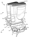
도 1은 예시적인 이중 의료용 용기 유닛 및 예시적인 투입 튜빙 세트를 특징으로 하는, 본 병합 장치의 제1 실시예의 사시도이다.
도 2는 유체 전달을 위한 예시적인 입구 포트 및 출구 포트, 및 대응하는 의료용 용기의 스토퍼를 천공하기 위해 병합 장치의 내측 표면 상에 횡방향으로 배치된 통합형 스파이크를 특징으로 하는, 도 1의 병합 장치의 평면도이다.
도 3은 투입 튜빙 세트에 탈착 가능하게 연결하기 위해 병합 장치의 외측 표면 상에 배치된 예시적인 출구 포트를 특징으로 하는, 도 2의 병합 장치의 부분 평면도이다.
도 4는 연결 이전의 2개의 인접한 병합 장치들의 예시적인 배열을 도시하는, 폐쇄 핀을 갖는 본 병합 장치의 제2 실시예의 사시도이다.
도 5는 연결 이후의 도 4의 병합 장치의 사시도이다.
도 6은 연결된 의료용 용기들 사이의 유체 경로의 예시적인 실례를 특징으로 하는, 도 5의 병합 장치의 개략적인 정면도이다.
도 7은 폐쇄 핀과 입구 및 출구 포트의 상이한 구성을 갖는 2개의 연결된 병합 장치들의 다른 예시적인 배열을 도시하는, 본 병합 장치의 제3 실시예의 측면 사시도이다.
도 8은 인접한 병합 장치들이 상호 연결될 때의 도 7의 병합 장치들의 후방 사시도이다.
도 9는 인접한 병합 장치들이 분리될 때의 도 7의 병합 장치의 후방 사시도이다.
도 10은 유체 연결 조립체 및 공기 연결 조립체를 갖는 누출 방지 메커니즘을 특징으로 하는, 도 5의 병합 장치의 개략적인 정면도이다.
도 10a는 2개의 힘-활성화 밸브의 예시적인 조합을 특징으로 하는 도 10의 누출 방지 메커니즘의 개략적인 정면도이다.
도 10b는 힘-활성화 밸브 및 일방향 체크 밸브의 예시적인 조합을 특징으로 하는, 도 10의 누출 방지 메커니즘의 개략적인 정면도이다.
도 10c는 스파이크 커넥터 및 접근 돔 밸브의 예시적인 조합을 특징으로 하는, 도 10의 누출 방지 메커니즘의 개략적인 정면도이다.
도 11은 인접한 병합 장치들이 누출 방지 메커니즘을 거쳐 상호 연결될 때의 도 10의 병합 장치들의 개략적인 정면도이다.
도 12는 도 10의 유체 연결 조립체의 분해된, 부분 수직 단면도이다.
도 13은 도 10의 공기 연결 조립체의 분해된, 부분 수직 단면도이다.
도 14는 유체 연결 조립체의 유체 경로를 도시하는, 도 10의 누출 방지 메커니즘의 수직 단면도이다.
도 15는 도 10의 누출 방지 메커니즘의 저면도이다.
도 16은 이중 의료용 용기 유닛을 가능케 하도록 구성된, 도 10의 누출 방지 메커니즘의 저면도이다.
도 17a는 도 1의 병합 장치와 함께 사용되도록 설계된 예시적인 캡 제거기의 상부 사시도이다.
도 17b는 도 17a의 캡 제거기의 저면 사시도이다.
도 17c - 도 17d는 도 17a의 캡 제거기의 예시적인 사용을 도시한다.
도 18은 소수성 필터 및 친수성 필터의 예시적인 조합을 특징으로 하는, 도 10의 누출 방지 메커니즘의 개략적인 정면도이다.
도 19는 본 병합 장치를 직렬 배열로 통합하는 예시적인 트레이의 분해 사시도이다.
도 20은 소수성 필터를 구비한 본 병합 장치를 특징으로 하는 예시적인 모듈형 유닛의 분해 사시도이다.1 is a perspective view of a first embodiment of the present merging device, featuring an exemplary dual medical container unit and an exemplary set of infusion tubing.
FIG. 2 is the merging device of FIG. 1 featuring exemplary inlet and outlet ports for fluid transfer, and integral spikes disposed transversely on the inner surface of the merging device to puncture a stopper of a corresponding medical container; is a plan view of
3 is a partial plan view of the merging device of FIG. 2 featuring an exemplary outlet port disposed on an outer surface of the merging device for removably connecting to a set of input tubing;
4 is a perspective view of a second embodiment of the present merging device with a closing pin, showing an exemplary arrangement of two adjacent merging devices prior to connection;
Fig. 5 is a perspective view of the merging device of Fig. 4 after connection;
FIG. 6 is a schematic front view of the merging device of FIG. 5 , featuring an illustrative illustration of a fluid pathway between connected medical containers;
7 is a side perspective view of a third embodiment of the present merging device, showing another exemplary arrangement of two connected merging devices having different configurations of closure pins and inlet and outlet ports;
Fig. 8 is a rear perspective view of the merging devices of Fig. 7 when adjacent merging devices are interconnected;
FIG. 9 is a rear perspective view of the merging device of FIG. 7 when adjacent merging devices are separated;
FIG. 10 is a schematic front view of the merging device of FIG. 5 featuring a leak containment mechanism having a fluid connection assembly and an air connection assembly;
10A is a schematic front view of the leak tight mechanism of FIG. 10 featuring an exemplary combination of two force-activated valves;
10B is a schematic front view of the leak containment mechanism of FIG. 10 featuring an exemplary combination of a force-activated valve and a one-way check valve;
10C is a schematic front view of the leak containment mechanism of FIG. 10 featuring an exemplary combination of a spike connector and an access dome valve;
Fig. 11 is a schematic front view of the merging devices of Fig. 10 when adjacent merging devices are interconnected via a leak-tight mechanism;
12 is an exploded, partial vertical cross-sectional view of the fluid connection assembly of FIG. 10 ;
13 is an exploded, partial vertical cross-sectional view of the air connection assembly of FIG. 10 ;
14 is a vertical cross-sectional view of the leak containment mechanism of FIG. 10 showing the fluid path of the fluid connection assembly;
Fig. 15 is a bottom view of the leak prevention mechanism of Fig. 10;
16 is a bottom view of the leak containment mechanism of FIG. 10 configured to enable a dual medical container unit;
17A is a top perspective view of an exemplary cap remover designed for use with the merging device of FIG. 1 ;
17B is a bottom perspective view of the cap remover of FIG. 17A ;
17C-17D illustrate an exemplary use of the cap remover of FIG. 17A .
18 is a schematic front view of the leak containment mechanism of FIG. 10 featuring an exemplary combination of a hydrophobic filter and a hydrophilic filter;
19 is an exploded perspective view of an exemplary tray incorporating the present merging device in a serial arrangement;
20 is an exploded perspective view of an exemplary modular unit featuring the present merging device with a hydrophobic filter.
본 병합 장치의 특정 실시예가 본원에서 설명되었지만, 본 병합 장치에 관련된 모든 구성요소들의 다른 대안적인 실시예들이 상이한 용도에 적합하도록 교환 가능하다. 본 출원에서 사용되는 바와 같은 "병합 장치"라는 용어는 환자에게 의약품 유체를 투여하기 위해 하나 이상의 의료용 용기로부터의 의약품 유체에 접근하기 위한 장치를 지칭한다. 따라서, 단일 용기 및 여러 의료용 용기들로부터 의약품 유체를 투여하기 위해 사용되는 병합 장치가 고려된다.Although specific embodiments of the present merging apparatus have been described herein, other alternative embodiments of all components related to the present merging apparatus are interchangeable to suit different uses. The term “merging device” as used herein refers to a device for accessing drug fluid from one or more medical containers for administering drug fluid to a patient. Accordingly, a single container and a combined device used for administering pharmaceutical fluids from multiple medical containers are contemplated.
이제 도 1 - 도 3을 참조하면, 본 병합 장치는 전체적으로 10으로 표시되고, 제1 의약품 유체를 저장하도록 구성된 제1 의료용 용기(14) 및 제2 의료용 유체를 저장하도록 구성된 제2 의약품 용기(16)를 갖는, 전체적으로 12로 표시된 의료용 용기 유닛으로부터 의약품 유체 또는 물질을 병합하도록 설계된다. 몇몇 실시예에서, 본 병합 장치(10)는 재사용으로부터의 잠재적인 오염을 회피하기 위한, 일회용 유닛이다. 위에서 설명된 바와 같이, 예시적인 이중 의료용 용기 유닛(12)이 참조로 통합된, 공동 양도된 미국 특허 제8,684,433호에 설명되어 있다. 다른 의약품 물질이 본 장치(10)와 함께 사용하기 위해 고려되지만, 하나의 실시예에서, 제1 의료용 용기(16)는 환자의 피하 공간 내의 기공을 확대시키는 효소를 담는다. 기공의 확대는 제2 용기(14) 내에 담겨 있는, 상대적인 높은 점성의 IG 유체의 높은 체적의 투입에 의한 전달을 용이하게 한다. 예를 들어, 효소가 없으면, IG 유체의 예상되는 투입은 단일 부위에서 대략 50mL이다. 그러나, 효소가 있으면, 600mL의 범위 내의 투입이 단일 투입 부위에서 달성될 수 있다.Referring now to FIGS. 1 - 3 , the present merging device, generally designated 10 , includes a first
2개의 의료용 용기(14, 16)를 갖는 용기 유닛(12)이 도시되어 있지만, 용기 유닛이 단일 용기(예컨대, 시린지, 바이알, 필름 주머니, 앰풀 등)를 갖는 것이 또한 고려된다. 하나의 실시예에서, 본 병합 장치(10)는 위에서 보았을 때 실질적인 직사각형 형상을 갖지만, 타원형, 정사각형, 및 다른 기하학적 형상과 같은 다른 적합한 형상이 고려된다. 임의의 개수 또는 조합의 의료용 용기들이 상이한 용도에 적합하도록 본 병합 장치(10)에 대해 사용될 수 있는 것이 또한 고려된다.Although
본 병합 장치(10) 내에, 의약품 유체 또는 주위 공기를 받도록 구성된 입구 포트(18)가 포함되고, 입구 포트는 병합 장치의 외벽(20) 상에 배치된다. 몇몇 실시예에서, 아래에서 더 상세하게 설명되는 바와 같이, 입구 포트(18)는 병합 장치들이 함께 결합될 때, 인접한 병합 장치로부터 의약품 유체를 받는다 (도 4 및 도 5). 그렇지 않으면, 입구 포트(18)는 병합 장치(10)가 인접한 병합 장치에 결합되지 않는 동안, 주위 공기를 흡인하기 위한 통기구로서 작용한다. 도 6에 관련하여 아래에서 설명되는 바와 같이, 병합 장치(10)들이 함께 결합될 때, 각각의 장치와 용기 사이에서의 공기의 적절한 통기는 의약품의 순차적인 전달을 향상시키는 것으로 발견되었다. 용기 유닛(12)의 구성에 의존하여, 입구 포트(18)는 사용 중에 의료용 용기(14, 16)에 대응하는 하나 이상의 입구 채널(22, 24)을 가질 수 있다.Included within the
병합 장치(10)로부터 의약품 유체를 전달하기 위해, 출구 포트(26)가 입구 포트(18)로부터의 병합 장치의 외벽(20)의 대향하는 측면 상에 배치되고, 인접한 병합 장치 또는 주입 튜빙 세트(28)와 같은, 다른 의료용 부착부로 의약품 유체를 전달하도록 구성된다. 몇몇 실시예에서, 주입 튜빙 세트(28)는 일 단부에서 병합 장치(10)의 출구 포트(26)에 그리고 대향 단부에서 병합 장치(10)로부터 의약품 유체를 흡인하기 위해, 연동 펌프 또는 투입 장치와 같은 펌핑 시스템(도시되지 않음)에 탈착 가능하게 연결된다. 대안적으로, 시린지(도시되지 않음)가 병합 장치(10)로부터의 의약품 유체의 진공 취출을 위해 출구 포트(26)에 도킹될 수 있다.For delivery of medication fluid from the merging
튜빙 세트(28) 내에서의 의약품 유체의 유동을 조절하는 것은 대응하는 튜빙의 종축에 대해 적어도 하나의 클램프(30)를 횡방향으로 조정함으로써 달성된다. 폐색 위치와 비폐색 위치 사이에서 전이하는 다른 클램핑 장치가 본 기술 분야에 공지된 바와 같이 고려된다. 입구 포트(18)에서의 경우에서와 같이, 출구 포트(26)는 사용 중에 의료용 용기(14, 16)에 대응하는 하나 이상의 출구 채널(32, 34)을 가질 수 있다.Controlling the flow of drug fluid within the tubing set 28 is accomplished by transversely adjusting the at least one
몇몇 실시예에서, 각각의 채널(22, 24, 32, 34)은 연결된 입구 포트(18)와 출구 포트(26) 사이 또는 출구 포트(26)와 투입 튜빙 세트(28) 사이의 마찰식 끼워 맞춤 또는 슬립 연결을 용이하게 하도록 대응하는 채널의 입구에 위치된, O-링 등과 같은 탄력적으로 변형 가능한 시일(36)을 갖는다. 제거 가능한 보호 커버(38)가 대응하는 입구 및 출구 채널(22, 24, 32, 34)을 접촉 또는 공기 오염으로부터 보호하기 위해 각각의 포트(18, 26) 위에 또는 둘레에 마찰식으로 끼워 맞춰진다는 점이 고려된다.In some embodiments, each
몇몇 실시예에서, 의료용 용기 유닛(12)의 삽입을 수용하도록 구성된 중심 개방부 또는 공동(40)이 제1 및 제2 의료용 용기(14, 16)로부터 제1 및 제2 의약품 유체를 병합하기 위해 제공된다. 공동(40) 내로의 의료용 용기 유닛(12)의 삽입 이전에, 의료용 용기 유닛의 상부 캡(42)이 제거되어, 대응하는 제1 및 제2 용기(14, 16)의 제1 및 제2 스토퍼(44, 46)를 노출시킨다. 스토퍼(44, 46)의 말단 멸균은 알코올, 과산화수소 등과 같은 소독제를 사용하여 수행된다.In some embodiments, a central opening or
제1 루멘 스파이크 또는 니들(48)이 제1 의료용 용기(14)의 제1 스토퍼(44)를 천공하기 위해 공동(40) 내에 배치되고, 제2 루멘 스파이크 또는 니들(50)이 제2 의료용 용기(16)의 제2 스토퍼(46)를 천공하기 위해 공동 내에 배치된다. 양 스파이크(48, 50)는 바람직하게는 스파이크가 대응하는 제1 및 제2 의료용 용기(14, 16)의 제1 및 제2 스토퍼(44, 46)를 동시에 천공하기 위해 기부로부터 수직으로 돌출하도록, 병합 장치(10)의 기부(54)의 내측 표면(52)에 일체로 횡방향으로 부착된다. 소정의 경우에, 대응하는 제1 및 제2 용기(14, 16)의 제1 및 제2 스토퍼(44, 46)는 상이한 용도에 적합하도록 분리되어 천공된다. 몇몇 실시예에서, 보호식 제거 가능 슬리브 또는 외피(56)가 각각의 스파이크의 예리한 단부 지점을 덮기 위해 각각의 스파이크(48, 50)에 대해 제공된다.A first lumen spike or
의약품 유체 전달의 개시는 용기 유닛이 상위 위치로부터 하위 위치로 전이하도록, 용기 유닛(12)을 뒤집고 공동(40) 내로 용기 유닛을 삽입함으로써 달성된다. 구체적으로, 이러한 도시된 실시예에서, 삽입 중에, 제1 및 제2 용기(14, 16)의 제1 및 제2 스토퍼(44, 46)는 각각 제1 및 제2 루멘 스파이크(48, 50) 대해 가압되어 그에 의해 천공된다. 슬리브(56)에 의해 제공되는 보호 시일이 용기 유닛(12)의 뒤집힘 및 하방 삽입 시에 뚫리는 것이 또한 고려된다. 이러한 도시된 실시예에서 공동(40)의 내벽(60) 상에 배치된, 편위식 클립 또는 클램프형 잠금 메커니즘(58)이 용기가 적절한 스파이크 위에 바르게 위치되지 않으면, 용기(14, 16)가 스파이크(48, 50)에 도달할 수 없도록, 용기 유닛(12)을 기부(54) 위에서 이격되게 유지하기 위해 제공된다.Initiation of drug fluid delivery is accomplished by inverting the
유닛(12) 내에서의 용기들의 적절한 배향을 용이하게 하도록, 도 2에서 보이는 바와 같이, 공동(40)은 용기 유닛(12)이 그가 올바른 배향으로만 삽입될 수 있도록 공동에 키이 결합되도록 치수 설정된다. 용기(14, 16)가 공동(40) 내에 적절하게 위치되면, 잠금 클립(58)은 용기의 존재에 의해 방사상 외측으로 밀리고, 이는 용기 유닛(12)이 기부(54)에 대해 하방으로 끼워지거나, 활주하거나, 이동하도록 허용하여, 용기와 지정된 스파이크(48, 50) 사이의 맞물림을 가능케 한다. 스파이크(48, 50)는 대응하는 용기(14, 16)의 스토퍼(44, 46)를 관통하고, 각각의 담겨 있는 의약품 유체의 전달을 개시한다.To facilitate proper orientation of the containers within the
제1 의약품 유체의 유체 전달을 용이하게 하도록, 제1 스파이크(48)는 대응하는 튜빙(64)을 거쳐 제1 입구 채널(22)에 연결되는 제1 스파이크 채널(62)을 갖는다. 아울러, 제1 스파이크(48)는 대응하는 튜빙(64)을 거쳐 제1 출구 채널(32)에 연결되는 제2 스파이크 채널(66)을 갖는다. 바람직한 실시예에서, 적어도 하나의 체크 밸브(68)가 의약품 유체의 방향성 유동을 선택적으로 제어하기 위해 튜빙(64) 내에 개재되거나 설치된다. "튜브" 또는 "튜빙"이라는 용어는 용도 및 구성 방법에 의존하여 다양한 단면 형상(예컨대, 원형, 정사각형, 또는 다른 형상)을 갖는, 본 병합 장치(10)로부터 분리되거나 그와 일체인 홈 등과 같은 임의의 고정식 또는 가요성 유체 통로 또는 경로를 포함하거나 그에 관련된 것임이 고려된다.To facilitate fluid transfer of the first medication fluid, the
튜빙(64)이 본 기술 분야에 공지된 바와 같이, 입구 포트(18), 스파이크(48, 50), 및 출구 포트(26)를 상호 연결하도록 구성되는 것이 고려된다. 결과적으로, 병합 장치(10)의 활성화 시에, 연속 유동 경로가 입구 포트(18)로부터 제1 용기(14)와 유체 연통하는 출구 포트(26)까지 확립된다. 도 10 - 도 16에 관련된 문단에서 아래에서 더 상세하게 설명되는 바와 같이, 소수성 필터가 공기는 통과하도록 허용하지만 의약품 유체가 병합 장치로부터 누출하는 것은 방지하기 위해 튜빙(64) 또는 병합 장치(10)의 다른 적합한 위치에서 사용되는 것이 또한 고려된다. 추가의 체크 밸브가 의약품 유체가 스파이크(48, 50)를 거쳐, 연결된 인접한 유닛으로 이동하는 것을 방지하기 위해 기부(54) 아래에 설치될 수 있다.It is contemplated that
더 구체적으로, 도 2에 도시된 바와 같이, 본 병합 장치(10)가 다른 병합 장치에 결합되지 않은 구성에서, 주위 공기가 펌핑 시스템의 작용 하에서, 제1 입구 채널(22), 대응하는 튜빙(64), 및 제1 스파이크(48)의 제1 스파이크 채널(62)을 거쳐 (도 2에서 점선으로 도시된) 제1 용기(14) 내로 흡인된다. 결과적으로, 제1 용기(14) 내의 제1 의약품 유체는 제1 스파이크(48)의 제2 스파이크 채널(66) 및 대응하는 튜빙(64)을 거쳐 제1 출구 채널(32)로 전달된다. 공기 및 제1 의약품 유체의 예시적인 유동 경로가 점선 화살표(A)에 의해 표시되어 있다.More specifically, as shown in FIG. 2 , in a configuration in which the
제1 의약품 유체의 전달이 완료되면, 제2 의약품 유체의 전달은 클램프(30)의 개방 및 닫힘을 제어함으로써 개시될 수 있다 (도 3). 제2 의약품 유체의 유체 전달을 용이하게 하도록, 제2 스파이크(50)는 대응하는 튜빙(64)을 거쳐 제2 입구 채널(24)에 연결되는 제1 스파이크 채널(70)을 갖는다. 아울러, 제2 스파이크(50)는 대응하는 튜빙(64)을 거쳐 제2 출구 채널(34)에 연결되는 제2 스파이크 채널(72)을 갖는다. 결과적으로, 병합 장치(10)의 활성화 시에, 다른 연속 유동 경로가 입구 포트(18)로부터 (도 2에서 점선으로 도시된) 제2 용기(16)와 유체 연통하는 출구 포트(26)까지 확립된다.When delivery of the first medication fluid is complete, delivery of the second medication fluid may be initiated by controlling the opening and closing of the clamp 30 ( FIG. 3 ). To facilitate fluid transfer of the second medication fluid, the
구체적으로, 제1 스파이크(48)에서의 경우에서와같이, 주위 공기가 펌핑 시스템의 작용 하에서, 제2 입구 채널(24), 대응하는 튜빙(64), 및 제2 스파이크(50)의 제1 스파이크 채널(70)을 거쳐 제2 용기(16) 내로 흡인된다. 결과적으로, 제2 용기(16) 내의 제2 의약품 유체는 제2 스파이크(50)의 제2 스파이크 채널(72) 및 대응하는 튜빙(64)을 거쳐 제2 출구 채널(34)로 전달된다. 공기 및 제2 의약품 유체의 예시적인 유동 경로가 점선 화살표(B)로 표시되어 있다.Specifically, as is the case with the
이제 도 2 및 도 4 - 도 6을 참조하면, 본 병합 장치(10)의 다른 실시예가 전체적으로 74a, 74b, 74c로 표시되어 있다. 도 4 - 도 6에서, 제1, 제2, 및 제3 병합 장치(74a, 74b, 74c)의 대응하는 구성요소들은 처음 3개의 알파벳(즉, "a", "b", "c") 표시를 갖는 도면 부호로 표시된다. 병합 장치(10)와 공유되는 구성요소들은 동일한 도면 부호로 표시된다. 병합 장치(74a, 74b, 74c)에 도시된 특정 실시예에서, 제1 및 제2 용기(14, 16)를 갖는 의료용 용기 유닛(12)은 미리 조립된 유닛으로서 병합 장치(74a, 74b, 74c)에 부착된다.Referring now to Figures 2 and 4-6, another embodiment of the
더 구체적으로, 용기(14, 16)의 제1 및 제2 스토퍼(44, 46)는 병합 장치(74a, 74b, 74c)의 공동(40) 내로 삽입되어, 제1 및 제2 스파이크(48, 50)에 의해 천공될 준비가 된다 (도 2). 본 병합 장치(74a, 74b, 74c)에서, 각각의 장치(74)가 멸균 유체 경로를 보장하기 위해, 감마선 등에 의해서와 같이, 말단 멸균되는 것이 고려된다. 스파이크(48, 50)는 용기(14, 16)가 눌릴 때 천공되고 압축되는 보호 외피(56)를 구비하고, 이에 의해 사용 시까지 스파이크를 깨끗하게 그리고 유체 경로를 멸균으로 유지한다.More specifically, the first and
그 다음, 장치(74) 및 용기 유닛(12)은 통기성 패키지 내로 조립되어 밀봉되고, 스토퍼(44, 46) 및 스파이크(48, 50)를 사용 시까지 살균된 상태로 유지하기 위해, 과산화수소 증기 등과 같은 소독제로 처리된다.
이러한 구성에서, 용기(14, 16)의 제1 및 제2 스토퍼(44, 46)는 제1 및 제2 스파이크(48, 50)에 의해 천공되도록 상위 위치에 미리 도달되거나 미리 위치된다. 그러나, 용기 유닛(12)의 상위 위치로부터 하위 위치로의 전이를 정지시키도록 구성된 폐쇄 메커니즘 또는 핀(76)이 사용 이전에 (예컨대, 운송 및 취급 중에) 병합 장치(74a, 74b, 74c)의 조기 활성화를 방지한다. 따라서, 핀(76)은 위에서 설명된 잠금 클립(58)과 유사한 기능을 수행한다. 폐쇄 핀(76)이 제1 용기(14)와 제2 용기(16) 사이에서 용기 유닛(12)의 본체(80) 상에 배치된 슬롯(78) 내로 삽입되는 것이 고려되지만, 폐쇄 핀의 다른 적합한 구성이 고려된다.In this configuration, the first and
폐쇄 핀(76)이 그를 본체(80)로부터 당겨냄으로써 분리된 후에, 파지 향상 목적으로 복수의 홈(84)을 갖는 압력 바(82)가 용기 유닛(12)의 상부 상에 배치되고, 용기 유닛을 상위 위치로부터 하위 위치로 전이시키도록 하방으로 밀린다. 용기 유닛(12)의 이러한 하방 이동은 용기(14, 16)의 제1 및 제2 스토퍼(44, 46)가 대응하는 제1 및 제2 스파이크(48, 50)에 의해 천공되게 한다.After the
도시된 실시예(74a, 74b, 74c)에서와 같은 본 병합 장치의 몇몇 실시예에서, 2개 이상의 병합 장치가 결합된 병합 장치들로부터의 의약품 유체의 비단속적인 공급을 확립하기 위해 각각의 병합 장치의 종축에 대해 상보적인 관계로 함께 직렬로 결합될 수 있다. 예를 들어, 도 4 및 도 5에 도시된 바와 같이, 제1 병합 장치(74a)의 입구 포트(18a)는 제2 병합 장치(74b)의 출구 포트(26b) 내로 삽입되어 그와 상보적으로 연결된다. 결국, 제2 병합 장치(74b)의 입구 포트(18b)는 모든 결합된 병합 장치(74a, 74b, 74c)들 사이에서의 유체 경로의 중단되지 않은 연결을 용이하게 하도록 제3 병합 장치(74c)의 출구(26c) 내로 삽입된다.In some embodiments of the present merging device, such as in the illustrated
이러한 구성에서, 제1, 제2, 및 제3 병합 장치(74a, 74b, 74c)는 의약품 유체의 비단속적이며, 연속적인 전달을 위한 병합 장치들 사이에서의 통로를 제공하기 위해 서로 유체 연통하여 연결 또는 결합된다. 예를 들어, 결합된 제1 용기(14a, 14b, 14c)들의 제1 의약품 유체들은 용기들의 단속 또는 조작이 없이 사용자에게 투여될 수 있다. 유사하게, 결합된 제2 용기(16a, 16b, 16c)들의 제2 의약품 유체들은 사용자에게 순차적으로 투여될 수 있다. 병합 장치(74a, 74b, 74c)들이 의료용 유체의 투여를 용이하게 하도록 임의의 다른 적합한 방식으로 배열될 수 있는 것이 고려된다. 아울러, 제1 및 제2 의약품 유체는 용도에 적합하도록 반대 순서로 사용자에게 전달될 수 있다.In this configuration, the first, second, and
이제 도 5 및 도 6을 참조하면, 3개의 결합된 제1 용기(14a, 14b, 14c)들의 유동 경로를 구비한 실시예가 예시의 목적으로 도시되어 있다. 이러한 구성에서, 주위 공기가 입구 포트(18c) 및 제1 스파이크(48c)의 제1 스파이크 채널(62c)을 거쳐 우측 제1 용기(14c) 내로 흡인된다. 제1 스파이크(48c)의 제2 스파이크 채널(66c)은 중간 제1 용기(14b) 내의 제1 스파이크(48b)의 제1 스파이크 채널(62b)에 연결된다. 유사하게, 제1 스파이크(48b)의 제2 스파이크 채널(66b)은 좌측 제1 용기(14a) 내의 제1 스파이크(48a)의 제1 스파이크 채널(62a)에 연결된다.Referring now to FIGS. 5 and 6 , an embodiment with a flow path of three coupled
다음으로, 제1 스파이크(48a)의 제2 스파이크 채널(66a)은 도 6에서 제1 용기(14a)의 좌측 상에 도시된 출구 포트(26a)를 거쳐 펌핑 시스템에 연결된다. 3개의 결합된 제2 용기(16a, 16b, 16c)들의 다른 유동 경로가 유사한 방식으로 확립된다.Next, the
작동 시에, 포트(26a)를 통해 펌핑 시스템에 의해 생성되는 음압 또는 흡입 압력이 제1 의약품 유체의 3개의 제1 용기(14a, 14b, 14c)로부터의 비단속적인 순차적 전달을 일으킨다. 시스템(74a - 74c)은 각각의 용기(14a - 14c)로부터의 의약품의 순차적 전달을 제공하기 위한 내장형 공기/유체 관리 특징부를 갖는다. 예를 들어, 초기에, 좌측 제1 용기(14a) 내의 유체는 진공이 그러한 용기(14a) 내의 유체의 수준 위에서 발현될 때까지, 포트(26a) 및 스파이크 채널(66a)을 거쳐 용기(14a)의 유체 내용물로 인가되는 흡입 압력에 의해 아래로 흡인된다. 이러한 진공 압력의 축적은 출구 채널(26b) 및 스파이크 채널(66b)로의 스파이크 채널(62a) 및 입구 채널(18a)의 유체 연결부를 거쳐 용기(14b)의 유체 내용물 상에서 흡입 압력을 생성한다.In operation, the negative or suction pressure generated by the pumping system via
다음으로, 중간의 제1 용기(14b) 내의 유체 내용물 상에 가해지는 흡입 압력은 유사한 진공이 그러한 용기 내의 유체의 수준 위에서 발현될 때까지, 내용물을 아래로 흡인한다. 진공이 용기(14a, 14b) 양쪽 내에서 발현되면, 흡입 압력이 출구 채널(26c) 및 스파이크 채널(66c)로의 스파이크 채널(62b) 및 입구 채널(18b)의 유체 연결부를 거쳐 용기(14c)의 유체 내용물 상에서 생성된다. 용기(14c)가 라인(18c)을 통해 주위로 통기되므로, 약간의 진공 압력만이 이러한 용기(14c)의 액체 내용물 위에서 생성된다. 대신에, 생성된 흡입 압력은 스파이크 채널(62c) 및 입구 포트(18c)를 거쳐 주위로 연통될 것이고, 이러한 용기(14c) 내로의 공기의 흡인을 일으킬 것이고, 이러한 용기는 먼저 비워질 것이다.Next, the suction pressure applied on the fluid contents in the intermediate
용기(14c)는 액체 수준이 스파이크 채널(66c)로의 입구 아래에 도달할 때까지 비어 있을 것이고, 이때 다음의 용기(14b)의 내부는 용기(14c)를 거쳐 주위로 노출되어, 용기(14b)의 유체 내용물이 펌핑 시스템의 흡입력 하에서 비워지도록 허용한다. 최종적으로, 용기(14b)가 비워진 후에, 용기(14a)가 그 다음 유사한 방식으로 비워진다. 따라서, 3개의 용기(14a, 14b, 14c)들은 모든 용기들이 비워질 때까지 원위에서 근위의 순서로 순차적으로 자동으로 투여된다.The
각각의 용기(14a, 14b, 14c)의 상이한 체적량은 이러한 순차적 유체 전달 과정에 영향을 주지 않는다. 표준 바이알의 예시적인 체적량은 25, 50, 100, 200, 및 300밀리리터를 포함하지만, 의료용 용기의 임의의 다른 적합한 크기 또는 조합이 고려된다. 이제 도 2 및 도 7 - 도 9를 참조하면, 본 병합 장치(74)의 또 다른 (제3) 실시예가 전체적으로 86a, 86b로 표시되어 있다. 도 7 - 도 9에서, 제1 및 제2 병합 장치(86a, 86b)의 대응하는 구성요소들은 처음 2개의 알파벳(즉, "a", "b") 표시를 갖는 도면 부호로 표시된다. 병합 장치(74)와 공유되는 구성요소들은 동일한 도면 부호로 표시된다. 병합 장치(86a, 86b)에서 특징적인 주요 차이점은 병합 장치들이 각각의 병합 장치의 종축에 대한 직렬 배열로 함께 결합되거나 직렬 연결되는 것이다.The different volumes of each
더 구체적으로, 각각의 병합 장치(86a, 86b)는 출구 포트(26a, 26b)를 수용하도록 구성된 제1 또는 좌측 날개(88a, 88b), 및 입구 포트(18a, 18b)를 수용하도록 구성된 제2 또는 우측 날개(90a, 90b)를 포함한다. 도 9에 도시된 제1 병합 장치(86a)에 관하여, 제1 및 제2 입구 채널(22a, 24a)은 제2 날개(90a) 상에 배치되고, 제1 및 제2 출구 채널(32a, 34a)은 제1 날개(88a) 상에 배치된다. 제2 병합 장치(86b)는 대응하는 입구 및 출구 채널에 대해 동일한 구성을 갖는다.More specifically, each merging
도 8 및 도 9에 도시된 바와 같이, 2개의 인접한 병합 장치(86a, 86b)들의 직렬 연결식 결합을 확립하기 위해, 제1 병합 장치(86a)의 제2 날개(90a)는 제2 병합 장치(86b)의 제1 날개(88b)와 상보적으로 연결된다. 더 구체적으로, 바람직한 실시예에서, 제2 날개(90a)는 병합 장치(86a, 86b)의 종축에 대해 횡방향인 축에 대해 제1 날개(88b)보다 더 높이 위치된다. 제1 날개(88b) 및 제2 날개(90a)의 상대 위치 및 구성이 위에서 설명된 배향으로부터 역전될 수 있음이 고려된다.8 and 9, in order to establish a series-connected coupling of two
제1 및 제2 입구 채널(22a, 24a)은 제2 날개(90a)의 하부 표면으로부터 하방으로 연장하고, 제1 및 제2 출구 채널(32b, 34b)은 제1 날개(88b)의 상부 표면으로부터 상방으로 연장하는 것이 또한 바람직하다. 따라서, 병합 장치(86a, 86b)들의 직렬 연결형 결합은 제1 병합 장치의 입구 채널(22a, 24a)이 상보적인 배열로 제2 병합 장치의 출구 채널(32b, 34b) 내로 삽입되도록, 제2 병합 장치의 제1 날개(88b) 상으로 아래로 제1 병합 장치의 제2 날개(90a)를 가압함으로써 달성된다.The first and
다시 도 2, 도 7, 및 도 9를 참조하면, 병합 장치(86a, 86b)의 다른 특징은 보호 커버(38)가 제1 및 우측 날개(88a, 88b, 90a, 90b)의 외형 또는 프로파일을 수용하도록 구성된 신장된 본체를 갖는 것이다. 선택적으로, 보호 커버(38)는 의약품 유체를 용기(16a, 16b)로부터 대응하는 출구 포트(26a, 26b)를 통해, 예를 들어, 보조 포트(92)에 도킹된 시린지 내로 전달하도록 구성된 보조 포트(92)를 갖는다. 보호 커버(38)는 의료용 유체를 다른 용기(14a, 14b)로부터 투입을 위해 환자에게 연결된 투입 펌프로 전달하도록 구성된 튜빙 세트를 또한 갖는다. 폐쇄 핀(76)(도 5) 대신에, 잠금 스페이서(94)가 용기 유닛(12)이 하위 위치로 전이하는 것을 방지하기 위해 제공된다. 초기에, 잠금 스페이서(94)는 용기 유닛(12)을 상위 위치에 잠그기 위해 대응하는 병합 장치(86a, 86b)의 상위 부분(98) 상에 배치된 원주방향으로 연장하는 환상 홈(96) 내로 삽입된다.Referring again to Figures 2, 7, and 9, another feature of the merging
폐쇄 핀(76)과 유사하게 작동되는 바와 같이, 잠금 스페이서(94)가 스페이서에 부착된 링(100)을 당김으로써 병합 장치(86a, 86b)로부터 제거된 후에, 용기 유닛(12)의 압력 바(82)는 용기 유닛을 상위 위치로부터 하위 위치로 전이시키도록 하방으로 밀린다. 용기 유닛(12)의 이러한 하방 이동은 용기(14, 16)의 제1 및 제2 스토퍼(44, 46)가 대응하는 제1 및 제2 스파이크(48, 50)에 의해 천공되게 한다.The pressure bar of the
이제 도 2, 도 6, 및 도 10을 참조하면, 예시적인 누출 방지 메커니즘이 전체적으로 102로 표시되어 있고, 병합 장치(10)로부터의 원치 않는 공기 또는 유체 누출을 방지하도록 설계된다. 병합 장치(10)와 공유되는 구성요소들은 동일한 도면 부호로 표시된다. 누출 방지 메커니즘(102) 내에, 병합 장치(10) 내의 유체 경로를 제어하도록 구성된, 전체적으로 104로 표시된 유체 연결 조립체, 및 병합 장치 내의 공기 통기 경로를 제어하도록 구성된, 전체적으로 106으로 표시된 공기 연결 조립체가 포함된다. 누출 방지 메커니즘(102)이 위에서 설명된 병합 장치(10, 74, 86)의 모든 실시예에 적용 가능한 것이 고려된다.Referring now to FIGS. 2 , 6 , and 10 , an exemplary leak containment mechanism, indicated generally at 102 , is designed to prevent unwanted air or fluid leakage from the merging
바람직한 실시예에서, 유체 연결 조립체(104)는 제1 용기(14)로부터의 의약품 유체의 유체 유동을 선택적으로 조절하기 위해 제1 병합 장치(74)의 출구 포트(26) 내로 통합되는 제1 유체 밸브(108)를 포함한다. 제1 유체 밸브(108)는 전형적으로 다른 장치 또는 튜빙 커넥터에 연결되지 않을 때 닫히고, 다른 장치 또는 튜빙 커넥터에 연결될 때 커넥터(114)를 거쳐 유체 유동을 허용하도록 기계식으로 개방된다. 유체 연결 조립체(104)는 제1 용기(14)로의 의약품 유체의 방향성 유체 유동을 선택적으로 조절하기 위해 제1 병합 장치(74)의 입구 포트(18)에 연결되는 제2 유체 체크 밸브(110)를 포함한다.In a preferred embodiment, the
제1 및 제2 유체 체크 밸브가 휴지 위치에 있을 때, 유체 체크 밸브(110)는 제1 용기 내의 의약품 유체가 용기로부터 누출되지 않도록, 제1 용기(14)를 행해서만 유체 경로를 허용하는 일방향 밸브인 점이 고려된다. 제1 밸브(108)는 다른 병합 장치의 제2 체크 밸브(110)에 해제 가능하게 상보적으로 연결되도록 구성된 제1 유체 경로 커넥터(112)를 갖는다. 선택적으로, 제2 체크 밸브(110)는 다른 병합 장치의 제1 체크 밸브(108)에 해제 가능하게 상보적으로 연결되도록 구성된 제2 유체 경로 커넥터(114)를 갖는다.When the first and second fluid check valves are in their rest positions, the
사용 중에, 제1 유체 밸브(108)는 병합 장치(74)가 다른 병합 장치에 연결되지 않을 때, 제1 용기(14)로부터의 유체 유동을 방지한다. 밸브는 다른 장치(74)에 연결될 때, 자유로운 유체 유동을 허용하도록 기계식으로 개방된다. 제2 유체 체크 밸브(110)는 장치(74)가 다른 병합 장치에 연결되지 않을 때, 커넥터(114)로부터의 누출을 방지하고, 또한 연결된 병합 장치(74)들 사이에서 원치 않는 누출을 방지한다. 유체 체크 밸브(110)의 예시적인 크래킹 압력은 밸브가 연결된 펌프에 의해 생성되는 유체 압력에 의해 개방되도록 허용하기 위해 평방 인치당 대략 3 - 5파운드(psi)이다.In use, first
병합 장치(74)의 방향성 공기 유동을 선택적으로 조절하기 위해, 공기 연결 조립체(106)는 소수성 필터(118)를 거쳐 제1 병합 장치(74)의 입구 포트(18)에 연결되는 공기 경로 커넥터(116)를 포함한다. 구체적으로, 소수성 필터(118)는 일 단부에서 공기 경로 커넥터(116)에 그리고 대향 단부에서 유체 체크 밸브(110)의 하류의 스파이크(48)에 연결된다. 본 기술 분야에 공지된 바와 같이, 소수성 필터(118)는 공기 통과는 허용하지만, 유체가 필터를 통해 이동하는 것은 방지한다. 따라서, 소수성 필터(118)는 공기 경로 커넥터(116)로부터의 의약품 유체의 원치 않는 누출을 방지한다. 대안적으로, 다른 적합한 친수성 필터가 또한 상이한 용도에 적합하도록 고려된다.To selectively regulate the directional airflow of the merging
막힌 공동(122)을 갖는 공기 경로 플러그 또는 단부 구성요소(120)가 공기 연결 조립체(106) 내에 제공되고, 다른 병합 장치의 공기 경로 커넥터(116)에 해제 가능하게 상보적으로 연결되도록 구성된다. 공기 경로 플러그(120)와 공기 경로 커넥터(116)가 정합식으로 또는 상보적으로 연결될 때, 병합 장치(74) 내의 공기 통기 경로는 막힌 공동(122)에 의해 폐쇄되거나 차단되고, 이에 의해 공기 누출을 효과적으로 방지한다.An air path plug or
이제 도 2, 도 6, 및 도 11을 참조하면, 제1 병합 장치(74a)가 제2 병합 장치(74b)에 결합되거나 직렬 연결되는 것이 고려된다 (도 11). 누출 방지 메커니즘(102a, 102b) 및 제1 및 제2 병합 장치(74a, 74b)의 대응하는 구성요소들은 처음 2개의 알파벳(즉, "a", "b") 표시를 갖는 도면 부호로 표시된다. 이러한 구성에서, 제2 공기 연결 조립체(106b)의 공기 경로 플러그(120b)는 제1 공기 연결 조립체(106a)의 공기 경로 커넥터(116a)에 정합식으로 또는 상보적으로 연결된다. 따라서, 제1 병합 장치(74a)와 제2 병합 장치(74b)가 결합되거나 직렬 연결될 때, 연결된 병합 장치들의 공기 통기 경로는 직렬 연결형 장치들 중 최원위 장치의 공기 통기 경로(예컨대, 제2 공기 연결 조립체(106b)의 공기 경로 커넥터(116b)에 의해 형성된 공기 통기 경로)를 제외하고 자동으로 닫히거나 차단된다.Referring now to FIGS. 2 , 6 , and 11 , it is contemplated that a
유체 경로에 관하여, 제2 유체 연결 조립체(104b)의 제1 유체 밸브(108b)의 제1 유체 경로 커넥터(112b)는 제1 유체 연결 조립체(104a)의 제2 유체 체크 밸브(110a)의 제2 유체 경로 커넥터(114a)에 정합식으로 또는 상보적으로 연결된다. 펌핑 시스템이 용기(14a)와 유체 연통하는 제1 유체 연결 조립체(104a)의 제1 유체 연결 밸브(108a)의 제1 유체 경로 커넥터(112a)에 연결되는 것이 또한 고려된다.With respect to the fluid path, the first
이러한 구성에서, 연결된 제1 밸브(108a, 108b)들은 펌핑 시스템과 병합 장치(74a, 74b) 사이의 유체 연통을 허용하기 위해 제1 유체 경로 커넥터(112a, 112b)에 의해 기계식으로 개방된다. 그러나, 제2 체크 밸브(110a, 110b)는 제2 병합 장치(74b)로부터 제1 병합 장치(74a)로의 유체 유동이 일방향 제2 체크 밸브(110a)에 의해 이미 수용되었기 때문에, 기계식으로 개방될 필요가 없다. 용기(14a, 14b)로부터의 유체 유동을 허용하지 않는 제1 밸브(108a, 108b)만이 기계식으로 개방된다.In this configuration, the connected
위에서 유사하게 설명된 바와 같이, 주위 공기가 공기 연결 조립체(106b)의 공기 경로 커넥터(116b) 및 소수성 필터(118b)를 거쳐 제2 병합 장치(74b)의 용기(14b) 내로 흡인된다. 동시에, 제2 병합 장치(74b)의 제2 유체 연결 조립체(104b)의 제2 체크 밸브(110b)는 용기(14b)로부터의 유체 누출을 방지한다. 결과적으로, 펌핑 시스템에 의해 생성되는 진공과 같은 음압은 임의의 원치 않는 유체 누출이 없이 용기(14a, 14b)로부터의 의약품 유체의 비단속적인 순차적 전달을 일으킨다.As similarly described above, ambient air is drawn into the
이제 도 10 및 도 12를 참조하면, 유체 연결 조립체(104)가 유체 연결 조립체의 수형 부재(128)의 삽입을 수용하도록 구성된 암형 부재 개방부(126)를 갖는 암형 부재(124)를 포함하는 것이 바람직하다. 수형 부재(128)에 암형 부재(124)를 확실히 부착하기 위해, 전체적으로 130으로 표시된 스냅 결합식 조립체 잠금 메커니즘이 유체 연결 조립체(104) 내에 제공되고, 수형 부재(124)와 암형 부재(128)를 함께 해제 가능하게 연결하도록 구성된다.Referring now to FIGS. 10 and 12 , it is apparent that the
바람직한 실시예에서, 잠금 메커니즘(130)은 암형 부재(124)의 측벽(134)의 내측 표면 상에 배치되는 적어도 하나의 잠금 탭 또는 돌출부(132), 및 수형 부재(128)의 외측 표면 상에 배치되는 적어도 하나의 만입부 또는 홈(136)을 포함한다. 수형 부재(128)가 암형 부재 개방부(126) 내로 활주식으로 삽입될 때, 잠금 메커니즘(130)의 잠금 탭(132)과 대응하는 만입부(136)는 암형 부재(124)와 수형 부재(128)를 제 위치에 확실히 유지하기 위해 정합식으로 래칭(latching)되고, 이에 의해 화살표(C)에 의해 표시된 바와 같은 의약품 유체의 방향성 유체 유동을 개시한다. 환상 잠금 및 해제 홈, 측방 날개 등과 같은 다른 잠금 메커니즘 구조가 고려된다.In a preferred embodiment, the
유체 연결 조립체(104)의 중요한 양태는 암형 부재(124)가 유체-밀봉 압축 시일을 제공하기 위해 암형 부재의 외측 상부 표면에 부착된 제1 밀봉 고정구(138)를 갖는 것이다. 제1 밀봉 고정구(138)가 제1 오목 측면(140) 및 대향하는 제1 볼록 측면(142)을 갖는 것이 고려되고, 시일은 압력이 제1 오목 측면(140) 또는 제1 볼록 측면(142)에 대해 인가될 때, 개방되도록 설계되는 점이 고려된다. 바람직하게는, 제1 밀봉 고정구(138)는 실질적인 돔 형상을 갖고, 가요성 탄성중합체 재료로 만들어진다. 미리 결정된 길이를 갖는 제1 슬릿 또는 간극(144)이, 슬릿이 휴지 시에 단단히 닫히지만 압력이 제1 오목 측면(140) 또는 제1 볼록 측면(142)에 대해 인가될 때 개방되도록, 제1 밀봉 고정구(138)의 실질적인 중심에 배치되는 것이 고려된다.An important aspect of the
더 구체적으로, 제1 밀봉 고정구(138)의 제1 슬릿(144)은 제1 밀봉 고정구가 휴지 위치에 있을 때, 의약품 유체의 유체 유동을 방지한다. 그러나, 펌핑 시스템에 의해 생성되는 음압이 제1 밀봉 고정구(138)의 볼록 측면(142)에 인가될 때, 제1 슬릿(144)은 화살표(C)에 의해 표시된 바와 같이, 의약품 유체의 유체 유동을 허용하도록 개방된다. 스프링 부하식 볼 체크 밸브, 덕빌 밸브, 우산 밸브, 다이어프램 밸브 등과 같은 다른 적합한 유형의 체크 밸브가 용도에 적합하도록 고려된다.More specifically, the
암형 부재(124)가 암형 부재의 종축을 따라 암형 부재 개방부(126) 내에서 암형 부재(124)의 내측 상부 표면의 실질적인 중심으로부터 현수하는 튜브형 칼럼(146)을 갖는 것이 또한 고려된다. 바람직하게는, 튜브형 칼럼(146)은 인입 기하학적 형상을 구비한 기울어지거나 경사진 외측 표면(148)을 가져서, 깔때기 형상 외벽을 생성한다. 구체적으로, 튜브형 칼럼(146)의 외경은 암형 부재(124)의 내측 상부 표면을 향해 점진적으로 증가된다. 정사각형, 직사각형, 육각형 형상과 같은 다른 적합한 기하학적 형상이 칼럼(146)에 대해 또한 고려된다.It is also contemplated that the
유체 연결 조립체(104)의 다른 중요한 양태는 수형 부재(128)가 실질적으로 튜브형이고, 유체-밀봉 압축 시일을 제공하기 위해 수형 부재의 내측 표면에 부착된 제2 밀봉 고정구(150)를 갖는 것이다. 제1 밀봉 고정구(138)에서와 같이, 제2 밀봉 고정구(150)는 제2 오목 측면(152) 및 대향하는 제2 볼록 측면(154)을 갖는다. 위에서 설명된 바와 같이, 제2 밀봉 고정구(150)는 제1 밀봉 고정구(138)와 동일한 구성을 갖고, 제1 밀봉 고정구와 동일한 방식으로 작동한다. 그러나, 제1 밀봉 고정구(138) 및 제2 밀봉 고정구(150)는 유체 연결 조립체(104)로부터의 유체 누출을 방지하기 위해 반대 배향으로 배치됨을 알아야 한다.Another important aspect of the
더 구체적으로, 제1 밀봉 고정구(138)는 제1 볼록 측면(142)이 화살표(C)에 의해 표시된 바와 같은, 유체 유동 방향으로 암형 부재의 종축을 따라 상방으로 향하도록, 암형 부재(124)의 외측 상부 표면 상에 배치된다. 대조적으로, 제2 밀봉 고정구(150)는 제2 볼록 측면(154)이 화살표(C)에 의해 표시된 바와 같은, 유체 유동 방향에 대항하여 수형 부재의 종축을 따라 하방으로 향하도록, 수형 부재(128)의 내측 표면 상에 배치된다. 따라서, 휴지 시에, 제2 밀봉 고정구(150)의 제2 슬릿 또는 간극(156)은 수형 부재(128)로부터의 의약품 유체의 유체 유동을 방지하고, 제1 밀봉 고정구(138)의 제1 슬릿 또는 간극(144)은 암형 부재(124)로부터의 의약품 유체의 유체 유동을 방지한다.More specifically, the
수형 부재(128)가 암형 부재(124)의 튜브형 칼럼(146)의 삽입을 수용하도록 구성된 암형 부재 개방부(158)를 갖는 것이 또한 고려된다. 중심 관통 구멍(162)을 갖는 탄성중합체 백업 와셔(160)가 수형 부재(128)의 내측 표면의 상단부 부근에 배치된다. 백업 와셔(160)의 중심 관통 구멍(162)이 암형 부재(124)의 튜브형 칼럼(146)의 삽입을 수용하도록 치수 설정되므로, 관통 구멍의 내경은 튜브형 칼럼의 최소 외경보다 약간 더 작다. 따라서, 암형 부재(124)의 튜브형 칼럼(146)이 백업 와셔(160)의 중심 관통 구멍(162) 내로 점진적으로 삽입됨에 따라, 유체-밀봉 억지 끼워 맞춤이 튜브형 칼럼과 백업 와셔 사이에 형성된다. 튜브형 칼럼(146)이 완전히 삽입되면, 이는 슬릿(156)을 강제 개방하고, 암형 부재(124)와 수형 부재(128) 사이의 유체 연통을 허용한다.It is also contemplated that the
이제 도 10 및 도 13을 참조하면, 공기 연결 조립체(106)가 공기 연결 조립체의 수형 부재(168)의 삽입을 수용하도록 구성된 암형 부재 개방부(166)를 갖는 암형 부재(164)를 포함하는 것이 바람직하다. 공기 연결 조립체(106)의 암형 부재(164)의 중요한 양태는 소수성 필터(118)가 암형 부재(164)의 내측 표면의 하단부 부근에 배치되는 것이다. 예를 들어, 소수성 필터(118)는 화학적 접착, 용제 결합, 초음파 용접, 또는 다른 종래의 체결 기술에 의해 암형 부재(164)의 내측 표면에 부착 가능하다.Referring now to FIGS. 10 and 13 , it is evident that the
수형 부재(168)의 강성 원통형 본체(170)는 수형 부재(168)가 암형 부재 개방부(166) 내로 점진적으로 삽입됨에 따라, 환상 돌출부가 외피와 암형 부재(164) 사이에서 기밀식 억지 끼워 맞춤을 생성하도록, 환상 돌출부(174)를 갖는 가요성 탄성중합체 외피(172)로 둘러싸인다. 따라서, 환상 돌출부(174)의 외경이 암형 부재 개방부(166)의 내경보다 약간 더 큰 것이 바람직하다. 수형 부재(168)의 중공 내측 부분(176)이 예시의 목적으로 도시되어 있지만, 임의의 적합한 중실 또는 반중실 재료가 용도에 적합하도록 수형 부재의 내측 부분 내로 분리되어 삽입되거나 그와 일체로 형성될 수 있다.The rigid
이제 도 2, 도 10 - 도 12, 및 도 14를 참조하면, 유체 연결 조립체(104)의 예시적인 유체 경로가 도 14에 도시되어 있다. 위에서 설명된 바와 같이, 펌핑 시스템이 유체 연결 조립체(104)의 수형 부재(128)에 연결되는 것이 고려된다. 펌핑 시스템은 병합 장치 상의 것과 유사한 암형 커넥터(124)를 구비한 튜빙 세트를 갖는다. 암형 커넥터(124)를 구비한 튜빙 세트가 병합 장치에 연결될 때, 암형 커넥터(124) 내부의 튜브형 칼럼(146)은 병합 장치의 수형 커넥터(128) 내의 슬릿(156)을 강제 개방하고, 이에 의해 의료용 용기(14)로부터 제2 스파이크 채널(66) 및 출구 포트(26)를 거친 의약품 유체의 유체 유동을 허용한다.Referring now to FIGS. 2 , 10 - 12 , and 14 , an exemplary fluid pathway of the
유체 연결 조립체(104)의 암형 부재(124)가 다른 인접한 병합 장치(74)의 수형 부재(128)에 연결될 때, 음압은 암형 부재의 제1 밀봉 고정구(138)가 개방되게 한다. 결과적으로, 인접한 병합 장치로부터의 의약품 유체는 제1 스파이크 채널(62) 및 입구 포트(18)를 거쳐 의료용 용기(14) 내로 유동하여, 결합되거나 직렬 연결된 병합 장치들로부터의 의약품 유체의 비단속적인 공급을 확립한다. 밀봉 고정구(138, 150) 및 와셔(160)가 합성 수지 또는 플라스틱, 고무 등과 같은 가요성의 탄력 있는 재료로 만들어지는 것이 고려된다. 다른 적합한 재료가 용도에 적합하도록 또한 고려된다.When the
병합 장치(74)의 의약품 유체의 유체 경로가 사출 성형된 조립체 내로 일체형 유닛으로서 통합되는 것이 고려된다. 예를 들어, 몇몇 실시예에서, 유체 연결 조립체(104)의 수형 부재(128)는 바람직하게는 수형 부재가 기부로부터 수직으로 돌출하도록, 병합 장치(74)의 기부(54)에 일체로 횡방향으로 부착된다. 이러한 구성에서, 도 8 및 도 9에 유사하게 도시된 바와 같이, 암형 부재(124)와 수형 부재(128)가 서로 연결될 때, 결합된 병합 장치들의 향상된 확실한 결합이 달성되고, 이에 의해 결합된 장치들의 원치 않는 분해를 방지한다. 암형 부재(124) 및 수형 부재(128)의 상대 위치 및 구성이 위에서 설명된 배향으로부터 역전될 수 있는 것이 또한 고려된다.It is contemplated that the fluid path of the pharmaceutical fluid of the merging
이제 도 10 - 도 12, 도 14, 및 도 15를 참조하면, 복수의 유체 및 공기 경로 홈(178)이 의약품 유체의 유체 경로의 적어도 일 부분을 형성하기 위해 병합 장치(74)의 기부(54) 내에 성형되는 것이 고려된다. 이러한 구성에서, 입구 포트(18) 및 출구 포트(26)는 스파이크(48)로부터 유체 연결 조립체(104) 및 공기 연결 조립체(106)로의 유체 및 공기 경로가 이음매 없이 전이되도록, 홈(178) 내로 단일 유닛으로서 통합된다.Referring now to FIGS. 10-12 , 14 , and 15 , a
더 구체적으로, 유체 경로에 관하여, 유체 연결 조립체(104)의 암형 부재(124)의 암형 부재 개방부(126)는 의료용 용기(14)와 유체 연통하는 홈(178)을 거쳐 스파이크(48)의 제1 스파이크 채널(62)에 연결되고, 스파이크(48)의 제2 스파이크 채널(66)은 다른 홈을 사용하여 유체 연결 조립체의 수형 부재(128)의 수형 부재 개방부(158)에 연결되고, 이에 의해 암형 부재(124)로부터 수형 부재(128)로의 연속적인 유체 경로를 형성한다.More specifically, with respect to the fluid pathway, the female member opening 126 of the
공기 통기 경로에 관하여, 공기 연결 조립체(106)의 암형 부재(164)의 암형 부재 개방부(166)는 공기 연결 조립체의 암형 부재가 공기 연결 조립체의 수형 부재(168)에 의해 막히지 않을 때, 주위 공기가 의료용 용기(14) 내로 흡인되도록, 의료용 용기(14)와 유체 연통하는 홈(178)을 거쳐 스파이크(48)의 제1 스파이크 채널(62)에 연결된다.With respect to the air vent path, the female member opening 166 of the
몇몇 실시예에서, 보호 플레이트(180)(도 14)가 홈(178)에 의해 형성된 유체 및 공기 경로를 덮어서 밀봉하기 위해 사용된다. 기부(54)에 대한 플레이트(180)의 부착은 화학적 접착, 용제 결합, 초음파 용접, 또는 다른 종래의 체결 기술에 의해 달성된다. 플레이트(180)의 형상은 홈의 형상에 의존하여 가변적이지만, 정사각형, 직사각형, 또는 타원형 형상과 같은 다른 적합한 기하학적 형상이 용도에 적합하도록 고려된다.In some embodiments, a protective plate 180 ( FIG. 14 ) is used to cover and seal the fluid and air pathways formed by the
이제 도 1, 도 2, 도 14, 및 도 16을 참조하면, 누출 방지 메커니즘(102)의 홈(178)의 다른 예시적인 배치가 도시되어 있고, 여기서 홈은 이중 의료용 용기 유닛(12)을 가능케 하도록 구성되고 배열된다. 유체 연결 조립체(104)의 대응하는 구성요소들은 처음 2개의 알파벳(즉, "a", "b") 표시를 갖는 도면 부호로 표시된다. 이러한 홈 구성의 중요한 양태는 2개의 분리되거나 구분된 유체 연결 조립체(104a, 104b)들이 누출 방지 메커니즘(102) 내에 포함되지만, 하나의 공기 연결 조립체(106)만이 포함되고 제1 및 제2 스파이크(48, 50)에 의해 공유되는 것이다.Referring now to FIGS. 1 , 2 , 14 , and 16 , another exemplary arrangement of a
구체적으로, 공기 연결 조립체(106)의 암형 부재(164)의 암형 부재 개방부(166)는 공기 연결 조립체의 암형 부재를 통해 받은 주위 공기가 제1 의료용 용기(14) 및 제2 의료용 용기(16) 모두 내로 동시에 유동하도록, 홈(178)을 거쳐 제1 스파이크(48)의 제1 스파이크 채널(62) 및 제2 스파이크(50)의 제1 스파이크 채널(70) 모두에 연결된다. 홈(178)의 "T" 형상 공기 통기 경로 배치가 예시의 목적으로 도시되어 있지만, "Y" 및 "V" 형상의 배치와 같은 다른 적합한 배열이 용도에 적합하도록 또한 고려된다.Specifically, the female member opening 166 of the
이제 도 2, 도 10a - 도 10c, 및 도 14를 참조하면, 유체 연결 조립체(104)가 유체의 방향성 유체 유동을 선택적으로 조절하기 위해 병합 장치(74)의 출구 포트(26)에 연결되는 제1 힘-활성화 밸브(182)(도 10a)를 포함하는 것이 또한 고려된다. 유사한 구성에서, 유체 연결 조립체(104)는 유체의 방향성 유체 유동을 선택적으로 조절하기 위해 병합 장치(74)의 입구 포트(18)에 연결되는 제2 힘-활성화 밸브(184)(도 10a)를 포함한다.Referring now to FIGS. 2 , 10A-10C , and 14 , a
예를 들어, 도 10b에 도시된 바와 같이, 제2 힘-활성화 밸브(184)는 유체 연결 조립체(104)로부터의 유체 누출을 방지하기 위해, 커넥터(114)로부터의 유체 유동이 제2 힘-활성화 밸브의 작동에 의해 제어되도록, 제2 유체 체크 밸브(110)와 제1 스파이크(48) 사이에 배치되고, 입구 포트(18)에 연결된다. 일방향 체크 밸브(186)가 유체의 방향성 유체 유동을 선택적으로 조절하기 위해 병합 장치(74)의 입구 포트(18) 및 출구 포트(26) 중 적어도 하나에 연결되는 것이 바람직하다.For example, as shown in FIG. 10B , the second force-activated
구체적으로, 제2 힘-활성화 밸브(184)를 활성화하여 입구 포트(18) 내에서의 유체 유동을 허용하기 위해, 제1 의료용 용기(14)는 화살표(D)(도 10b)에 의해 표시된 바와 같이, 제1 의료용 용기를 상위 위치로부터 하위 위치로 전이시키도록 하방으로 밀린다. 제1 의료용 용기(14)의 이러한 하방 이동은 제1 의료용 용기(14)의 상부 부분(188)이 대응하는 힘-활성화 밸브(184)를 눌러서 커넥터(114)로부터의 유체 유동을 허용하게 한다. 역으로, 제2 힘-활성화 밸브(184)가 활성화되지 않을 때, 유체 유동은 입구 포트(18) 내에서 방지된다. 입구 포트(18) 및 출구 포트(26)에 연결되는 유체 또는 공기 유동을 따른 다른 적합한 위치가 상이한 용도에 적합하도록 또한 고려된다.Specifically, to activate the second force-activated
유사하게, 도 10a에 도시된 제1 힘-활성화 밸브(182) 또는 제2 힘-활성화 밸브(184)의 활성화는 병합 장치(74)의 유체 연결 조립체(104)의 제1 유체 경로 커넥터(112)를 다른 병합 장치의 유체 연결 조립체(104)의 제2 유체 경로 커넥터(114)에 정합식으로 또는 상보적으로 상호 연결함으로써 달성된다. 위에서 설명된 바와 같이, 2개의 인접한 병합 장치(74a, 74b)들의 예시적인 상호 연결이 도 11에 도시되어 있다.Similarly, activation of the first force-activated
스파이크(48, 50)들 중 적어도 하나가 병합 장치(74)의 입구 포트(18)와 출구 포트(26)를 유체 연통식으로 연결하도록 구성된 (도 14에서 점선으로 도시된) 스파이크 외피(190)로 둘러싸이는 것이 또한 고려된다. 예를 들어, 초기 위치에서, 스파이크 외피(190)는 제1 스파이크(48)의 제1 스파이크 채널(62) 및 제2 스파이크 채널(66)을 동시에 그리고 확실히 둘러싸고, 이에 의해 병합 장치(74)의 입구 포트(18)와 출구 포트(26) 사이에서의 공기 유동 또는 유체 유동을 허용한다.At least one of the
그러나, 도 10b에 도시된 바와 같이, 스파이크 외피(190)는 용기(14)가 눌릴 때, 천공 가능하며 압축 가능하다. 위에서 설명된 바와 같이, 제1 의료용 용기(14)가 화살표(D)에 의해 표시된 바와 같이, 상위 위치로부터 하위 위치로 전이할 때, 스파이크 외피(190) 또한 용기(14)의 상부 부분(188)에 의해 도 14에 도시된 상위 위치로부터 도 10b에 도시된 하위 위치로 하방으로 밀린다. 용기(14)의 이러한 이동에 의해, 스파이크 외피(190)는 파단되고, 입구 포트(18)와 출구 포트(26) 사이의 유체 유동이 달성된다.However, as shown in FIG. 10B , the
이제 도 10c 및 도 14를 참조하면, 유체 연결 조립체(104)는 스파이크 커넥터(192) 및 접근 돔 밸브(194)를 포함한다. 스파이크 커넥터(192)는 병합 장치(74)의 입구 포트(18)에 연결되고, 접근 돔 밸브(194)는 병합 장치의 출구 포트(26)에 연결되는 것이 바람직하다. 위에서 설명된 바와 같이, 접근 돔 밸브(194)는 도 14에 도시된 스냅 결합식 잠금 메커니즘(130)의 제2 밀봉 고정구(150)와 유사한 구성을 갖는다. 이러한 구성에서, 접근 돔 밸브(194)는 상보적인 관계로 스파이크 커넥터(192)의 삽입을 수용하도록 구성된 개방부 또는 관통 구멍(162)을 갖는다.Referring now to FIGS. 10C and 14 , the
이제 도 1, 도 8, 및 도 17a - 도 17d를 참조하면, 병합 장치(74)는 병합 장치들 중 적어도 하나에 부착되고 대응하는 용기의 상부 캡(42)을 제거하도록 구성된 캡 제거기(198)를 포함한다. 바람직한 실시예에서, 캡 제거기(198)는 헤드 영역(202) 및 테일 영역(204)을 갖는 중심 공동(200)을 포함하고, 헤드 영역 및 테일 영역은 공동 둘레에서 서로로부터 대향하는 배향으로, 바람직하게는 내측으로 배치된다. 사용 시에, 캡 제거기(198)의 헤드 영역(202)은 상부 캡(42)과 맞물리거나 이를 파지하고, 화살표(E)(도 17c)에 의해 표시된 바와 같이, 상부 캡을 개방하기 위해 테일 영역(204) 부근의 지점 둘레에서 피벗한다. 캡 제거기(198)의 실질적인 원형 또는 타원형 형상이 예시의 목적으로 도 17a - 도 17c에 도시되어 있지만, 다면형 또는 불규칙형 형상과 같은 다른 적합한 형상 또는 설계가 용도에 적합하도록 고려된다.Referring now to FIGS. 1 , 8 , and 17A-17D , a merging
도 17d에 도시된 바와 같이, 캡 제거기(198)의 헤드 영역(202)이 바람직하게는 병합 장치(10)의 기부(54)와 일체로 형성되는 것이 또한 고려된다. 이러한 구성에서, 캡 제거기(198)의 헤드 영역(202)은 테일 영역(204)이 없이 병합 장치(10)의 기부(54)에 고정식으로 부착된다. 사용 중에, 의료용 용기 유닛(12)의 상부 캡(42)은 기부(54)에서의 헤드 영역(202)이 용기의 상부 캡과 맞물리거나 꼭 맞게 끼워질 수 있도록, 병합 장치(10)에 이웃하여 뒤집힌 위치로 위치된다. 다음으로, 용기(14)는 용기가 화살표(E')에 의해 표시된 바와 같이, 상부 캡을 개방하기 위해 병합 장치(10)로부터 멀리 당겨지도록, 상부 캡(42)에 대해 헤드 영역(202)에 대향하는 지점에 둘레에서 피벗한다.It is also contemplated that the
이제 도 1, 도 10, 및 도 18을 참조하면, 몇몇 실시예에서, 유체 연결 조립체(104)가 소수성 필터(206) 및 친수성 필터(208) 중 적어도 하나를 포함하는 것이 고려된다. 몇몇 실시예에서, 소수성 필터(206)는 병합 장치의 방향성 공기/유체 유동을 선택적으로 조절하기 위해 병합 장치(10)의 입구 포트(18)에 연결된다. 역으로, 친수성 필터(208)는 병합 장치의 방향성 유체 및 공기 유동을 선택적으로 조절하기 위해 병합 장치(10)의 출구 포트(26)에 연결된다.Referring now to FIGS. 1 , 10 , and 18 , in some embodiments, it is contemplated that the
이중 의료용 용기 유닛(12)을 가능케 하도록 구성되고 배열된 도 18의 예시적인 구성에서, 제1 소수성 필터(206')가 제1 의약품 유체를 저장하도록 구성된 제1 의료용 용기(14)를 위한 제1 입구 포트(18')에 연결된다. 유사하게, 제2 소수성 필터(206")가 제2 의약품 유체를 저장하도록 구성된 제2 의료용 용기(16)를 위한 제2 입구 포트(18")에 연결된다. 따라서, 제1 및 제2 소수성 필터(206', 206")가 입구 포트(18', 18")로부터의 임의의 원치 않는 유체 누출이 없이 공기가 통기되도록 허용하는 것이 유리하다.In the exemplary configuration of FIG. 18 , constructed and arranged to enable a dual
제1 또는 제2 의약품 유체의 방향성 유체 유동을 선택적으로 제어하기 위해, 친수성 필터(208)는 제1 의료용 용기(14)를 위한 제1 출구 포트(26') 및 제2 의료용 용기(16)를 위한 제2 출구 포트(26") 모두에 연결된다. 이러한 구성에서, 친수성 필터(208)는 유리하게는 그가 제1 또는 제2 의약품 유체에 의해 습윤될 때까지 공기가 통기되도록 허용하고, 그 후에 친수성 필터는 의약품 유체만이 유체 경로 커넥터(112)를 통해 이동하도록 허용한다.To selectively control the directional fluid flow of the first or second medicinal fluid, the
단지 일례로서, 제1 의료용 용기(14)가 유체가 비워지면, 친수성 필터(208)는 공기가 친수성 필터를 통과하여 환자 내로 투입되는 것을 방지한다. 공기의 이러한 차단은 또한 임의의 유체 유동을 정지시키고, 펌프가 경보음을 울리게 하고, 이는 환자/보호자에게 제2 의료용 용기(16)로의 유동 경로를 개방하기 위해 위치 밸브(216)를 이동시키도록 신호한다. 다음으로, 펌프 작동은 제2 의료용 용기(16)의 내용물을 투입하기 위해 재개된다. 친수성 필터(208)가 또한 출구 포트(216") 내에 설치되면, 친수성 필터는 의료용 용기(16)가 비어 있을 때, 공기가 필터를 통과하여 환자 내로 투입되는 것을 방지한다. 공기의 이러한 차단은 임의의 유체 유동을 정지시키고, 펌프가 경보음을 울리게 하고, 이는 환자/보호자에게 제2 의료용 유체의 투입이 완료되었음을 신호한다. 소수성 필터(206) 및 친수성 필터(208)의 다른 적합한 배열이 상이한 용도에 적합하도록 또한 고려된다.By way of example only, when the first
이제 도 1, 도 6, 도 7, 도 10, 도 11, 및 도 19를 참조하면, 트레이 부재(210)가 직렬 배열로 결합된 적어도 하나의 본 병합 장치(74)를 포함하여, 병합 장치를 유체 연통식으로 트레이 부재 내로 통합하는 것이 고려된다. 도 19에서, 4개의 병합 장치(74)가 트레이 부재(210) 내로 통합되어 있지만, 병합 장치들의 임의의 개수 또는 실시예가 용도에 적합하도록 고려된다. 적어도 하나의 유동 경로 또는 통로(214)를 갖는 유동 커버(212)가 병합 장치(74)들 사이의 유체 연통을 용이하게 하도록 트레이 부재(210)에 부착된다. 제1 유동 통로(214')가 제1 의료용 용기(14)와 연결되도록 제공되고, 분리된 제2 유동 통로(214")가 제2 의료용 용기(16)와 연결되도록 제공되는 것이 바람직하다. 이러한 예에서, 트레이 부재(210)는 유체 연통식으로 트레이 부재 내로 통합된 복수의 병합 장치(74)를 포함한다. 아울러, 트레이 부재(210)는 2개의 분리된 유체를 제1 및 제2 의료용 용기(14, 16)로부터 출구 포트(52)로 이송하도록 구성된 2개의 분리된 튜브 또는 통로(214', 214")를 포함한다. 도 1, 도 6, 및 도 11에 도시된 병합 장치(10)와 공유되는 구성요소들은 동일한 도면 부호로 표시된다.Referring now to FIGS. 1 , 6 , 7 , 10 , 11 , and 19 , a
트레이 부재(210)가 제1 의료용 용기(14) 및 제2 의료용 용기(16) 중 적어도 하나로부터의 유체 경로를 선택적으로 허용하거나 조절하도록 구성된 위치 밸브(216)를 포함하는 것이 바람직하다. 예를 들어, 위치 밸브(216)는 제1 및/또는 제2 의료용 용기(14, 16)로부터의 유체 유동을 선택적으로 허용하고 차단하도록 구성된 비틀림 밸브를 갖는 수동 스위치 또는 스탑콕(stopcock)이다. 위치 밸브(216)가 튜빙 세트(28)가 트레이 부재(210)로부터 탈착될 때, 유체 유동을 방지하기 위한 밸브식 접근을 제공하는 것이 또한 고려된다. 바람직한 실시예에서, 스파이크 캡(218)이 스파이크 외피(190) 및 스파이크(48, 50)를 보호하기 위해 제공된다. 일례로서, 도 19에서, 유체 경로 커넥터(112)는 위치 밸브(216)에 의해 지점(108)에서 하나의 경로에 대해 다른 경로로 교체된다. 위치 밸브(216)가 루어 로크 커넥터를 갖고, 사용자가 어떤 유체가 사용자에게 전달되는 지를 제어하도록 축방향으로 회전 가능한 것이 고려된다.It is preferred that the
이제 도 1, 도 4, 도 7 - 도 9, 및 도 20을 참조하면, 병합 장치(74, 86a)가 적층 가능하고 결합 가능한 모듈형 유닛으로서 구성되고 배열되는 것이 바람직하다. 병합 장치(10, 74, 86a)와 공유되는 구성요소들은 동일한 도면 부호로 표시된다. 도 4 및 도 7 - 도 9에 유사하게 도시된 바와 같이, 병합 장치(86a)가 출구 포트(26a)를 수용하도록 구성된 제1 날개(88a) 및 입구 포트(18a)를 수용하도록 구성된 제2 날개(90a)를 포함하는 것이 고려된다.Referring now to FIGS. 1 , 4 , 7 - 9 , and 20 , it is preferred that the merging
제1 및 제2 의약품 유체의 원치 않는 누출을 방지하기 위해, 도 20에 도시된 바와 같이, 예를 들어, 제1 소수성 필터(118')가 입구 포트(18a)에 배치되어 제1 스파이크(48)에 연결되고, 제2 소수성 필터(118")가 제2 날개(90a)에 배치되어 제2 스파이크(50)에 연결된다. 소수성 필터(118', 118")의 다른 적합한 배열이 상이한 용도에 적합하도록 고려된다.To prevent undesired leakage of the first and second pharmaceutical fluids, for example, a first
도 20에 도시된 바와 같이, 병합 장치(86a)가 각각의 스파이크(48, 50)로부터의 유체 유동을 용이하게 하도록 적어도 하나의 전용 유동 경로 또는 통로(214', 214")를 갖는 유동 커버(212)를 포함하는 것이 고려된다. 각각의 유동 경로(214', 214")는 분할 부재(220)를 사용하여 대응하는 스파이크(48, 50)의 스파이크 채널(62, 66, 70, 72)에 따라 양분되거나 분리된다. 적어도 하나의 보호 플레이트 또는 커버(222)가 병합 장치(86a)와 관련된 노출된 유체 또는 공기 경로 또는 통로를 밀봉하도록 제공되는 것이 또한 고려된다. 아울러, 적어도 하나의 캡 부재(224)가 병합 장치(86a)와 관련된 유체 또는 공기 경로 또는 통로를 탈착 가능하게 차단하도록 제공된다.20, a flow cover having at least one dedicated flow path or
본 병합 장치의 특정 실시예가 본원에서 설명되었지만, 변화 및 변형이 더 넓은 양태에서의 본 개시용으로부터 벗어남이 없이 그리고 다음의 청구범위에서 설명되는 바와 같이, 본 병합 장치에 대해 이루어질 수 있음이 본 기술 분야의 통상의 기술자에 의해 이해될 것이다.Although specific embodiments of the present merging device have been described herein, it is to be understood that changes and modifications may be made to the present merging device without departing from its use in its broader aspects and as set forth in the claims that follow. It will be understood by one of ordinary skill in the art.
Claims (58)
유체 또는 주위 공기를 받도록 구성된 적어도 하나의 입구 채널(22, 24);
용기 유닛으로부터 유체를 전달하도록 구성된 제1 출구 채널(32) 및 제2 출구 채널(34);
2개의 분리된 유체를 용기 유닛으로부터 제1 및 제2 출구 채널로 이송하도록 구성된 제1 유동 통로(214') 및 분리된 제2 유동 통로(214'')로서, 제1 유동 통로는 용기 유닛의 제1 용기(14)로부터 제1 출구 채널로 제1 유체를 이송하고, 분리된 제2 유동 통로는 용기 유닛의 제2 용기(16)로부터 제2 출구 채널로 제2 유체를 이송하는, 제1 유동 통로 및 분리된 제2 유동 통로;
용기 유닛(12)의 삽입을 수용하도록 구성된 공동(40); 및
상기 공동 내에 배치되고, 용기 유닛이 상위 위치로부터 하위 위치로 전이할 때, 용기 유닛의 스토퍼(44, 46)를 천공하도록 구성된 적어도 하나의 스파이크(48, 50)
를 포함하는, 병합 장치.A merging device (10) for merging a first fluid and a second fluid from a vessel unit (12) having a first vessel (14) and a second vessel (16), the merging device comprising:
at least one inlet channel (22, 24) configured to receive a fluid or ambient air;
a first outlet channel (32) and a second outlet channel (34) configured to convey a fluid from the container unit;
A first flow passageway (214') and a second separate flow passageway (214'') configured to convey two separate fluids from the container unit to first and second outlet channels, the first flow passageway being the first flow passageway of the container unit. a first fluid passing from the first vessel 14 to the first outlet channel, and a separate second flow passage conveying a second fluid from the second vessel 16 of the vessel unit to the second outlet channel a flow passageway and a separate second flow passageway;
a cavity 40 configured to receive insertion of the container unit 12; and
at least one spike (48, 50) disposed within the cavity and configured to puncture a stopper (44, 46) of the container unit when the container unit transitions from an upper position to a lower position
A merging device comprising a.
유체를 저장하도록 구성된 적어도 하나의 용기(14, 16)를 갖는 용기 유닛(12)으로서, 상기 용기 유닛은 상기 병합 장치에 부착되는, 용기 유닛;
유체 또는 주위 공기를 받도록 구성된 적어도 하나의 입구 채널(22, 24);
용기 유닛(12)으로부터 유체를 전달하도록 구성된 적어도 하나의 출구 채널(32, 34);
상기 적어도 하나의 용기(14, 16)로부터 유체를 병합하기 위해 상기 용기 유닛(12)의 삽입을 수용하도록 구성된 공동(40); 및
상기 공동 내에 배치되고, 상기 용기 유닛이 상위 위치로부터 하위 위치로 전이할 때, 상기 적어도 하나의 용기의 스토퍼(44, 46)를 천공하도록 구성된 적어도 하나의 스파이크(48, 50)
를 포함하고,
상기 병합 장치(10)는 결합된 병합 장치들로부터의 유체의 비단속적인 공급을 확립하기 위해 상보적인 관계로 다른 병합 장치와 직렬로 결합되는,
병합 장치.A merging device (10) for merging pharmaceutical fluids,
a container unit (12) having at least one container (14, 16) configured to store a fluid, the container unit being attached to the merging device;
at least one inlet channel (22, 24) configured to receive a fluid or ambient air;
at least one outlet channel (32, 34) configured to convey fluid from the container unit (12);
a cavity (40) configured to receive the insertion of said container unit (12) for merging fluid from said at least one container (14, 16); and
at least one spike (48, 50) disposed within the cavity and configured to puncture a stopper (44, 46) of the at least one container when the container unit transitions from an upper position to a lower position
including,
wherein the merging device (10) is coupled in series with another merging device in a complementary relationship to establish an uninterrupted supply of fluid from the coupled merging devices;
merge device.
Priority Applications (1)
| Application Number | Priority Date | Filing Date | Title |
|---|---|---|---|
| KR1020227002928A KR102506175B1 (en) | 2015-06-19 | 2016-06-17 | Pooling device for single or multiple containers |
Applications Claiming Priority (3)
| Application Number | Priority Date | Filing Date | Title |
|---|---|---|---|
| US201562182099P | 2015-06-19 | 2015-06-19 | |
| US62/182,099 | 2015-06-19 | ||
| PCT/US2016/038136 WO2016205687A1 (en) | 2015-06-19 | 2016-06-17 | Pooling device for single or multiple containers |
Related Child Applications (1)
| Application Number | Title | Priority Date | Filing Date |
|---|---|---|---|
| KR1020227002928A Division KR102506175B1 (en) | 2015-06-19 | 2016-06-17 | Pooling device for single or multiple containers |
Publications (2)
| Publication Number | Publication Date |
|---|---|
| KR20180019184A KR20180019184A (en) | 2018-02-23 |
| KR102358218B1 true KR102358218B1 (en) | 2022-02-04 |
Family
ID=56204078
Family Applications (3)
| Application Number | Title | Priority Date | Filing Date |
|---|---|---|---|
| KR1020227002928A KR102506175B1 (en) | 2015-06-19 | 2016-06-17 | Pooling device for single or multiple containers |
| KR1020237006872A KR20230035149A (en) | 2015-06-19 | 2016-06-17 | Pooling device for single or multiple containers |
| KR1020187001386A KR102358218B1 (en) | 2015-06-19 | 2016-06-17 | Merging units for single or multiple containers |
Family Applications Before (2)
| Application Number | Title | Priority Date | Filing Date |
|---|---|---|---|
| KR1020227002928A KR102506175B1 (en) | 2015-06-19 | 2016-06-17 | Pooling device for single or multiple containers |
| KR1020237006872A KR20230035149A (en) | 2015-06-19 | 2016-06-17 | Pooling device for single or multiple containers |
Country Status (26)
| Country | Link |
|---|---|
| US (3) | US11219578B2 (en) |
| EP (2) | EP3310321B1 (en) |
| JP (3) | JP6993965B2 (en) |
| KR (3) | KR102506175B1 (en) |
| CN (1) | CN108040465A (en) |
| AU (3) | AU2016278966B2 (en) |
| BR (2) | BR112017026182B1 (en) |
| CA (1) | CA2988793C (en) |
| CO (1) | CO2017012908A2 (en) |
| CY (1) | CY1122643T1 (en) |
| DK (1) | DK3310321T3 (en) |
| ES (1) | ES2733467T3 (en) |
| HK (1) | HK1254346B (en) |
| HR (1) | HRP20191101T1 (en) |
| HU (1) | HUE043928T2 (en) |
| LT (1) | LT3310321T (en) |
| MX (2) | MX2017016684A (en) |
| MY (1) | MY184064A (en) |
| PL (1) | PL3310321T3 (en) |
| PT (1) | PT3310321T (en) |
| RS (1) | RS59206B1 (en) |
| RU (1) | RU2737287C2 (en) |
| SI (1) | SI3310321T1 (en) |
| TR (1) | TR201910248T4 (en) |
| TW (2) | TWI783262B (en) |
| WO (1) | WO2016205687A1 (en) |
Families Citing this family (15)
| Publication number | Priority date | Publication date | Assignee | Title |
|---|---|---|---|---|
| SI3310321T1 (en) | 2015-06-19 | 2019-10-30 | Baxalta Inc | Pooling device for single or multiple containers |
| JP2021523774A (en) * | 2018-05-11 | 2021-09-09 | ブリストル−マイヤーズ スクイブ カンパニーBristol−Myers Squibb Company | Devices and systems for delivery of combination therapies |
| MX2020013308A (en) * | 2018-06-05 | 2021-05-12 | Deka Products Lp | Reservoir devices, methods and systems. |
| USD893046S1 (en) | 2018-10-03 | 2020-08-11 | Baxalta GmbH | Container unit |
| CA3114876A1 (en) * | 2018-10-03 | 2020-04-09 | Takeda Pharmaceutical Company Limited | Packaging for multiple containers |
| JP2022504164A (en) | 2018-10-03 | 2022-01-13 | 武田薬品工業株式会社 | Drug delivery device |
| US20210369958A1 (en) * | 2018-10-03 | 2021-12-02 | Takeda Pharmaceutical Company Limited | Pooling device for single or multiple medical containers |
| TWM607320U (en) * | 2019-10-25 | 2021-02-11 | 黃景清 | Loop system using negative pressure delivery |
| CN114667127A (en) * | 2019-11-08 | 2022-06-24 | 百时美施贵宝公司 | Alternative fluid paths for serially connectable drug modules |
| CN114727905A (en) * | 2019-11-08 | 2022-07-08 | 百时美施贵宝公司 | Piston valve for serially connectable drug modules of a combination drug delivery device |
| CN115461028A (en) | 2020-03-05 | 2022-12-09 | 武田药品工业株式会社 | Medical fluid delivery device |
| IL298637B2 (en) * | 2020-05-29 | 2023-10-01 | Legacy Us Inc | Fluid mixing apparatus such as a ventilator |
| USD1002837S1 (en) | 2021-03-05 | 2023-10-24 | Takeda Pharmaceutical Company Limited | Medicament access device |
| WO2023017035A1 (en) | 2021-08-09 | 2023-02-16 | Wella Germany Gmbh | Hair coloring compositions comprising hydroxyalkyl amines as alkalising agents |
| WO2023042096A1 (en) | 2021-09-14 | 2023-03-23 | Takeda Pharmaceutical Company Limited | Facilitated delivery of concentrated antibody formulations using hyaluronidase |
Citations (3)
| Publication number | Priority date | Publication date | Assignee | Title |
|---|---|---|---|---|
| US4863049A (en) | 1987-10-12 | 1989-09-05 | Mect Corporation | Cap for a vessel |
| US20040241041A1 (en) | 1998-09-15 | 2004-12-02 | Archie Woodworth | Apparatus and method for fabricating a reconstitution assembly |
| WO2013162959A1 (en) | 2012-04-26 | 2013-10-31 | Baxter International Inc. | Packaging for multiple medical containers |
Family Cites Families (141)
| Publication number | Priority date | Publication date | Assignee | Title |
|---|---|---|---|---|
| US363690A (en) | 1887-05-24 | Box for bottles | ||
| US2080947A (en) | 1936-01-16 | 1937-05-18 | Joseph C Ligeour | Bottle carrier and cap remover |
| US2399893A (en) | 1944-06-08 | 1946-05-07 | Scholz Rudolph | Bottle lugger |
| US2754962A (en) | 1953-02-17 | 1956-07-17 | Harper D Scrymgeour | Bottle closure-opener |
| US2949204A (en) | 1954-12-31 | 1960-08-16 | Illinois Tool Works | Closure device |
| US2865669A (en) | 1955-07-26 | 1958-12-23 | Frank R Linthicum | Bottle carrier |
| US3278007A (en) | 1964-07-24 | 1966-10-11 | Walter L Weber | Multicolor paint kit |
| US3593873A (en) | 1968-05-22 | 1971-07-20 | Nl Wapen En Munitefabr | Container for cylindrical articles |
| US3543355A (en) | 1968-07-05 | 1970-12-01 | Charles A Wyckoff | Connector for tubular golf club bag separators |
| US3589509A (en) | 1968-12-13 | 1971-06-29 | Continental Can Co | Combination carrier and can opener |
| US3601253A (en) | 1969-06-06 | 1971-08-24 | Illinois Tool Works | Container-packaging device and method |
| US3876377A (en) | 1969-11-06 | 1975-04-08 | Vixotab Sarl | Device for chemical analyses |
| FR2085307A1 (en) | 1970-04-07 | 1971-12-24 | Milly Lucien | |
| US3744661A (en) | 1971-06-11 | 1973-07-10 | Ciba Geigy | Tamperproof container for vials or the like |
| US3727749A (en) | 1971-07-01 | 1973-04-17 | Graber Rogg Inc | Tamper-proof container |
| US3893280A (en) | 1972-06-21 | 1975-07-08 | Burns Biotec Lab Inc | Transfer packaging for biologicals |
| US3882909A (en) * | 1973-07-05 | 1975-05-13 | Ims Ltd | Trans-a-jet 1 |
| US4143764A (en) | 1976-09-20 | 1979-03-13 | Moss Iii L Howard | Shipper container for flasks |
| US4178152A (en) | 1977-02-24 | 1979-12-11 | Sanki Engineering Ltd. | Cell fragility testing method and appliance therefor |
| US4262814A (en) | 1979-06-18 | 1981-04-21 | Champion International Corporation | Device for detecting tampering with a capped container and blank therefor |
| US4402691A (en) | 1981-07-24 | 1983-09-06 | The Clinipad Corporation | Aseptic connection barrier system and method |
| US4405315A (en) | 1982-04-23 | 1983-09-20 | Stephen R. Ash | Spike exchanger for continuous ambulatory peritoneal dialysis |
| US4557727A (en) | 1982-04-23 | 1985-12-10 | Handt Alan E | Spike exchanger for continuous ambulatory peritoneal dialysis |
| US4526756A (en) | 1982-05-10 | 1985-07-02 | Evergreen Industries, Inc. | Device for interconnecting specimen collecting tubes |
| USD280932S (en) | 1983-03-30 | 1985-10-08 | United States Surgical Corporation | Surgical staple |
| USD283640S (en) | 1983-11-09 | 1986-04-29 | Healthcheck Corporation | Pregnancy test kit |
| US4915689A (en) | 1984-06-13 | 1990-04-10 | Alza Corporation | Parenteral delivery system comprising a vial containing a beneficial agent |
| US4759756A (en) | 1984-09-14 | 1988-07-26 | Baxter Travenol Laboratories, Inc. | Reconstitution device |
| US4713064A (en) | 1985-04-30 | 1987-12-15 | Sherwood Medical Company | Enteral feeding devices |
| US4970053A (en) | 1986-07-11 | 1990-11-13 | Beckman Instruments, Inc. | Reagent cartridge |
| DE3644088A1 (en) | 1986-12-23 | 1988-07-07 | Schering Ag | SAFETY TRANSPORT SYSTEM FOR DANGEROUS OR VALUABLE CHEMICALS |
| US4850972A (en) | 1987-01-16 | 1989-07-25 | Pacesetter Infusion, Ltd. | Progammable multiple pump medication infusion system with printer |
| EP0285424B1 (en) | 1987-04-02 | 1992-08-12 | Drg Flexpak Limited | Apparatus for contacting material such as a drug with a fluid |
| US5005721A (en) | 1987-05-08 | 1991-04-09 | Abbott Laboratories | Vial seal |
| US4795429A (en) | 1987-10-28 | 1989-01-03 | Feldstein Marvin A | Method and apparatus for use in the control of intravenous medication introduction |
| US4915688A (en) | 1987-12-03 | 1990-04-10 | Baxter International Inc. | Apparatus for administering solution to a patient |
| USD306645S (en) | 1987-12-14 | 1990-03-13 | V-Tech, Inc. | Pregnancy test kit |
| US5117997A (en) | 1988-06-16 | 1992-06-02 | Fink James J | Disposal container and transport case for infectious and hazardous waste material |
| US4873921A (en) | 1988-07-14 | 1989-10-17 | Piane Caterers, Inc. | Multiple unit wok apparatus |
| US4856647A (en) | 1988-08-19 | 1989-08-15 | Dahne Cynthia F | Apparatus for connecting containers |
| DE3833036C2 (en) | 1988-09-29 | 1998-03-19 | Bernd Hansen | Double chamber container |
| GB8922542D0 (en) | 1989-10-06 | 1989-11-22 | Melland Tristan Guy | Multi-compartment bottle |
| US5037390A (en) | 1989-12-28 | 1991-08-06 | Kenneth Raines | System and method for mixing parenteral nutrition solutions |
| US5040678A (en) | 1990-06-07 | 1991-08-20 | Transpan Company | Biological sample transport container |
| US5148919A (en) | 1991-05-17 | 1992-09-22 | Kevin J. Kitson | Blood tube safety box |
| US5236135A (en) | 1991-05-23 | 1993-08-17 | Ecomed, Inc. | Medical waste treatment system |
| JPH06509253A (en) | 1991-07-22 | 1994-10-20 | アボツト・ラボラトリーズ | Reusable seals for diagnostic test reagent packs |
| US5431509A (en) | 1991-11-25 | 1995-07-11 | Minnesota Mining And Manufacturing Company | Interlocking module system |
| US5304165A (en) | 1991-12-09 | 1994-04-19 | Habley Medical Technology Corporation | Syringe-filling medication dispenser |
| AU5331194A (en) | 1992-10-21 | 1994-05-09 | F.H. Faulding & Co. Limited | Multi-part package |
| USD355260S (en) | 1993-07-01 | 1995-02-07 | Eastman Kodak Company | Integrated holder of reagent bottles |
| US5322668A (en) | 1993-07-01 | 1994-06-21 | Eastman Kodak Company | Locked bottle holder |
| FR2715131B1 (en) | 1994-01-14 | 1996-04-05 | Kerplas Snc | Presentation set for at least one container. |
| US5725499A (en) | 1994-05-11 | 1998-03-10 | Plas-Pak Industries, Inc. | Dual barreled syringe and methods of assembly and use |
| US7074205B1 (en) | 1995-03-13 | 2006-07-11 | Cardinal Health 303, Inc. | Method and apparatus for power connection in a modular patient care system |
| US5941846A (en) | 1995-03-13 | 1999-08-24 | Alaris Medical Systems, Inc. | Method and apparatus for power connection in a modular patient care system |
| US5836910A (en) | 1995-03-13 | 1998-11-17 | Alaris Medical Systems, Inc. | Method and apparatus for logical addressing in a modular patient care system |
| US5582222A (en) | 1995-03-29 | 1996-12-10 | Johnson & Johnson Clinical Diagnostics, Inc. | Bottle closure mechanism using a sliding shutter |
| US5669502A (en) | 1995-04-17 | 1997-09-23 | Berlex Laboratories, Inc. | Vial holder |
| JPH08324571A (en) | 1995-06-06 | 1996-12-10 | Kirin Brewery Co Ltd | Handle for carrying bottle |
| US5873731A (en) | 1995-10-20 | 1999-02-23 | Eagle Simulation, Inc. | Patient drug recognition system |
| US5897526A (en) * | 1996-06-26 | 1999-04-27 | Vaillancourt; Vincent L. | Closed system medication administering system |
| US5785701A (en) * | 1996-09-17 | 1998-07-28 | Becton Dickinson And Company | Sterile vial connector assembly for efficient transfer of liquid |
| US5954213A (en) | 1996-12-27 | 1999-09-21 | Lever Brothers Company | Dual container and individual chamber therefor |
| GB9702056D0 (en) | 1997-01-31 | 1997-03-19 | Wallace Cameron & Company Limi | Container |
| GB2321892B (en) | 1997-02-07 | 2000-10-25 | Alligator Sales Ltd | Container |
| WO1998057681A1 (en) | 1997-06-16 | 1998-12-23 | Elan Corporation Plc | Drug delivery kit and method of packaging the same |
| EP1003579B1 (en) | 1997-08-22 | 2005-01-12 | Deka Products Limited Partnership | System and cassette for mixing and delivering intravenous drugs |
| US6159192A (en) | 1997-12-04 | 2000-12-12 | Fowles; Thomas A. | Sliding reconstitution device with seal |
| TW410024U (en) | 1998-09-05 | 2000-10-21 | Inventec Corp | Upright object supporting assembling device |
| US6719719B2 (en) | 1998-11-13 | 2004-04-13 | Elan Pharma International Limited | Spike for liquid transfer device, liquid transfer device including spike, and method of transferring liquids using the same |
| US6645181B1 (en) | 1998-11-13 | 2003-11-11 | Elan Pharma International Limited | Drug delivery systems and methods |
| US6558628B1 (en) | 1999-03-05 | 2003-05-06 | Specialty Silicone Products, Inc. | Compartment cover, kit and method for forming the same |
| US6355024B1 (en) | 1999-07-14 | 2002-03-12 | Mallinckrodt Inc. | Medical fluid delivery system |
| US6305541B1 (en) | 1999-09-15 | 2001-10-23 | John C. Tanner | Cartridge assembly packaging |
| US6213529B1 (en) | 1999-10-18 | 2001-04-10 | Marcia L. Kurcz | Propane tank and accessory carrier |
| USD457949S1 (en) | 2000-01-11 | 2002-05-28 | John Andrew Krug | Multiple chamber infusion pump |
| US6508791B1 (en) | 2000-01-28 | 2003-01-21 | Ramon Guerrero | Infusion device cartridge |
| US6474375B2 (en) * | 2001-02-02 | 2002-11-05 | Baxter International Inc. | Reconstitution device and method of use |
| IL161123A0 (en) | 2001-10-19 | 2004-08-31 | Monogen Inc | Article handling system and method |
| JP2003265608A (en) * | 2002-03-14 | 2003-09-24 | Terumo Corp | Collecting tool |
| MXPA04011395A (en) | 2002-05-16 | 2005-02-17 | Scott Lab Inc | Drug container entry mechanisms and method. |
| DE10244424B4 (en) | 2002-09-24 | 2008-07-31 | Ivoclar Vivadent Ag | applicator |
| US7135027B2 (en) | 2002-10-04 | 2006-11-14 | Baxter International, Inc. | Devices and methods for mixing and extruding medically useful compositions |
| DE10308401A1 (en) | 2003-02-27 | 2004-09-23 | Dräger Medical AG & Co. KGaA | Device for dosing medicinal substances |
| US7025389B2 (en) | 2003-06-06 | 2006-04-11 | Baxter International Inc. | Method and device for transferring fluid |
| US7234592B2 (en) | 2003-06-27 | 2007-06-26 | Fujifilm Corporation | Photographic processing agent cartridge and container usable therein |
| US6789828B1 (en) | 2003-08-04 | 2004-09-14 | Oregon Precision Industries, Inc. | Stabilizing two-bottle carrier |
| US20050045495A1 (en) | 2003-08-25 | 2005-03-03 | Dalsing Troy A. | Reusable container for contact lenses and other materials |
| US7837167B2 (en) * | 2003-09-25 | 2010-11-23 | Baxter International Inc. | Container support device |
| DE102004021789A1 (en) | 2004-05-03 | 2006-04-27 | Boehringer Ingelheim International Gmbh | Atomizers for dispensing liquids for medical purposes |
| US7468049B2 (en) * | 2005-06-14 | 2008-12-23 | Rieke Corporation | Dual syringe adapter |
| EP1993503A1 (en) * | 2006-03-06 | 2008-11-26 | Novo Nordisk A/S | A drug mixing device |
| US20090062732A1 (en) * | 2006-03-17 | 2009-03-05 | Novo Nordisk A/S | Connectable Device and a Device Assembly for Delivering a Liquid Drug |
| US20070278245A1 (en) | 2006-04-13 | 2007-12-06 | Michael Brooks | Tooth care product capsules and container |
| JP5062639B2 (en) | 2006-04-24 | 2012-10-31 | ノボ ノルディスク ヘルス ケア アーゲー | Transfer system for forming a drug solution from a lyophilized drug |
| US20070267378A1 (en) | 2006-05-17 | 2007-11-22 | Eastman Kodak Company | Multi-chambered container |
| US7607541B2 (en) | 2006-10-23 | 2009-10-27 | Deborah Girgis | Liquid medication storage and dispensing unit |
| USD620603S1 (en) | 2007-02-08 | 2010-07-27 | Biokit S.A. | Reagent container pack |
| US8545440B2 (en) | 2007-12-21 | 2013-10-01 | Carticept Medical, Inc. | Injection system for delivering multiple fluids within the anatomy |
| US20090166361A1 (en) | 2007-12-29 | 2009-07-02 | Airsec | Two-part, flip top, snap cap for vials |
| US8034044B2 (en) | 2008-04-04 | 2011-10-11 | B. Braun Melsungen Ag | Systems and methods for combining materials |
| US8506547B2 (en) | 2008-07-28 | 2013-08-13 | Nordson Corporation | Device and method for transferring fluids within a surgical environment |
| CN102186447B (en) * | 2008-10-15 | 2013-06-19 | 诺沃—诺迪斯克保健股份有限公司 | System for reconstitution of powdered drug |
| CA2757953A1 (en) | 2009-04-08 | 2010-10-14 | Mallinckrodt Llc | Vacuum assist syringe filling |
| EP2437715B1 (en) * | 2009-06-02 | 2018-01-17 | Yukon Medical, LLC | Multi-container transfer and delivery device |
| EP2448614B1 (en) | 2009-07-01 | 2018-10-10 | Fresenius Medical Care Holdings, Inc. | Drug delivery devices and related systems and methods |
| IT1395128B1 (en) * | 2009-07-30 | 2012-09-05 | Petrone | DEVICE / SYSTEM FOR MIXING LIQUIDS, DRUGS AND SOLUTIONS BEFORE ADMINISTRATION INSIDE THE HUMAN BODY |
| DE202009012540U1 (en) | 2009-09-17 | 2010-10-28 | J. Söllner GmbH | Adapter arrangement for supplying an injection liquid |
| USD632802S1 (en) | 2010-03-08 | 2011-02-15 | Salinas Victor R | Protective cover for a pharmaceutical vial |
| WO2011139921A2 (en) | 2010-04-29 | 2011-11-10 | Yukon Medical, Llc | Multi-container fluid transfer and delivery device |
| KR101899449B1 (en) * | 2010-08-25 | 2018-09-17 | 박스앨타 게엠베하 | Assembly to facilitate user reconstitution |
| USD645973S1 (en) | 2010-11-22 | 2011-09-27 | Beckman Coulter, Inc. | Reagent cartridge for holding reagents in a chemistry analyzer |
| EP2462913A1 (en) | 2010-12-10 | 2012-06-13 | Fresenius Medical Care Deutschland GmbH | Insert and vial for the infusion of liquids |
| ES2545998T3 (en) | 2010-12-30 | 2015-09-17 | Ge Healthcare Limited | Multivial dispensing |
| JP5980215B2 (en) | 2011-01-24 | 2016-08-31 | 大塚製薬株式会社 | Medical device containing cake-like composition containing aripiprazole as active ingredient, and cake-like composition containing aripiprazole as active ingredient |
| JPWO2012132829A1 (en) | 2011-03-25 | 2014-07-28 | テルモ株式会社 | Double-ended needle and mixing device |
| CN202184989U (en) | 2011-06-22 | 2012-04-11 | 成都市新津事丰医疗器械有限公司 | Self-destruction bag type infusion set |
| CN202236710U (en) | 2011-09-05 | 2012-05-30 | 成都市新津事丰医疗器械有限公司 | Self-destroying bag type infusion apparatus |
| AU2012324021A1 (en) | 2011-12-22 | 2013-07-11 | Icu Medical, Inc. | Fluid transfer devices and methods of use |
| JP6062871B2 (en) | 2011-12-29 | 2017-01-18 | 株式会社大塚製薬工場 | Exposure prevention cover, exposure prevention cover module including the same, chemical supply system, and chemical supply method |
| EP2822526B1 (en) | 2012-03-09 | 2017-01-18 | Sensile Pat AG | Drug reconstitution system |
| TWM455382U (en) | 2013-01-30 | 2013-06-21 | Univ Hsiuping Sci & Tech | Wind power generation charging device for helmet |
| US20150045289A1 (en) | 2013-07-15 | 2015-02-12 | Alchemia Oncology Pty Limited | Method of pre-preparing medications for therapeutic uses |
| US10627417B2 (en) | 2013-11-05 | 2020-04-21 | Siemens Healthcare Diagnostics Inc. | Reagent container anti-evaporation tube |
| US10500133B2 (en) | 2014-07-18 | 2019-12-10 | Tomas A. Caquias | Multi-mix infusion bag |
| USD769456S1 (en) | 2015-02-20 | 2016-10-18 | Siemens Healthcare Diagnostics Inc. | Reagent pack |
| SI3310321T1 (en) | 2015-06-19 | 2019-10-30 | Baxalta Inc | Pooling device for single or multiple containers |
| USD778460S1 (en) | 2015-07-17 | 2017-02-07 | Aseptic Technologies, S.A. | Vial |
| USD865993S1 (en) | 2017-05-03 | 2019-11-05 | Stratec Se | Docking cap |
| US20200170884A1 (en) | 2017-07-20 | 2020-06-04 | Janssen Biotech, Inc. | Drug mixing device |
| USD847974S1 (en) | 2017-09-12 | 2019-05-07 | Bioq Pharma Inc. | Two bottle enclosed desktop dispenser |
| USD847634S1 (en) | 2018-01-30 | 2019-05-07 | Kao Corporation | Holder for packing container |
| TWD194378S (en) | 2018-03-19 | 2018-12-01 | 立晏企業有限公司 | Part of the oil filling barrel |
| USD902428S1 (en) | 2018-04-20 | 2020-11-17 | Q-Linea Ab | Apparatus for medical tests |
| US20210369958A1 (en) | 2018-10-03 | 2021-12-02 | Takeda Pharmaceutical Company Limited | Pooling device for single or multiple medical containers |
| USD890358S1 (en) | 2018-10-03 | 2020-07-14 | Baxalta GmbH | Container unit |
| USD886611S1 (en) | 2018-10-03 | 2020-06-09 | Baxalta GmbH | Container unit |
| USD893046S1 (en) | 2018-10-03 | 2020-08-11 | Baxalta GmbH | Container unit |
| CA3114876A1 (en) | 2018-10-03 | 2020-04-09 | Takeda Pharmaceutical Company Limited | Packaging for multiple containers |
| EP4070106A1 (en) | 2019-12-06 | 2022-10-12 | Spout | Devices, compositions and methods for use in detecting contaminating heavy metals in water sources |
-
2016
- 2016-06-17 SI SI201630293T patent/SI3310321T1/en unknown
- 2016-06-17 CN CN201680035766.0A patent/CN108040465A/en active Pending
- 2016-06-17 AU AU2016278966A patent/AU2016278966B2/en active Active
- 2016-06-17 TR TR2019/10248T patent/TR201910248T4/en unknown
- 2016-06-17 KR KR1020227002928A patent/KR102506175B1/en active IP Right Grant
- 2016-06-17 TW TW109129643A patent/TWI783262B/en active
- 2016-06-17 PT PT16732203T patent/PT3310321T/en unknown
- 2016-06-17 EP EP16732203.1A patent/EP3310321B1/en active Active
- 2016-06-17 PL PL16732203T patent/PL3310321T3/en unknown
- 2016-06-17 DK DK16732203.1T patent/DK3310321T3/en active
- 2016-06-17 BR BR112017026182-0A patent/BR112017026182B1/en active IP Right Grant
- 2016-06-17 MY MYPI2017704842A patent/MY184064A/en unknown
- 2016-06-17 RS RSP20190790 patent/RS59206B1/en unknown
- 2016-06-17 ES ES16732203T patent/ES2733467T3/en active Active
- 2016-06-17 LT LTEP16732203.1T patent/LT3310321T/en unknown
- 2016-06-17 MX MX2017016684A patent/MX2017016684A/en unknown
- 2016-06-17 HU HUE16732203A patent/HUE043928T2/en unknown
- 2016-06-17 JP JP2018517677A patent/JP6993965B2/en active Active
- 2016-06-17 EP EP19169568.3A patent/EP3569216A1/en active Pending
- 2016-06-17 KR KR1020237006872A patent/KR20230035149A/en not_active Application Discontinuation
- 2016-06-17 US US15/186,061 patent/US11219578B2/en active Active
- 2016-06-17 RU RU2018101863A patent/RU2737287C2/en active
- 2016-06-17 TW TW105119134A patent/TWI705811B/en active
- 2016-06-17 BR BR122020014232-4A patent/BR122020014232B1/en active IP Right Grant
- 2016-06-17 CA CA2988793A patent/CA2988793C/en active Active
- 2016-06-17 WO PCT/US2016/038136 patent/WO2016205687A1/en active Application Filing
- 2016-06-17 KR KR1020187001386A patent/KR102358218B1/en active IP Right Grant
-
2017
- 2017-12-15 CO CONC2017/0012908A patent/CO2017012908A2/en unknown
- 2017-12-18 MX MX2020005654A patent/MX2020005654A/en unknown
-
2018
- 2018-10-18 HK HK18113422.1A patent/HK1254346B/en unknown
-
2019
- 2019-06-18 HR HRP20191101TT patent/HRP20191101T1/en unknown
- 2019-07-16 CY CY20191100754T patent/CY1122643T1/en unknown
-
2020
- 2020-01-17 US US16/746,583 patent/US11684548B2/en active Active
-
2021
- 2021-03-01 AU AU2021201307A patent/AU2021201307B2/en active Active
- 2021-12-10 JP JP2021200630A patent/JP7356487B2/en active Active
-
2023
- 2023-02-03 AU AU2023200572A patent/AU2023200572A1/en active Pending
- 2023-05-11 US US18/316,151 patent/US20230355475A1/en active Pending
- 2023-09-22 JP JP2023158182A patent/JP2023166612A/en active Pending
Patent Citations (3)
| Publication number | Priority date | Publication date | Assignee | Title |
|---|---|---|---|---|
| US4863049A (en) | 1987-10-12 | 1989-09-05 | Mect Corporation | Cap for a vessel |
| US20040241041A1 (en) | 1998-09-15 | 2004-12-02 | Archie Woodworth | Apparatus and method for fabricating a reconstitution assembly |
| WO2013162959A1 (en) | 2012-04-26 | 2013-10-31 | Baxter International Inc. | Packaging for multiple medical containers |
Also Published As
Similar Documents
| Publication | Publication Date | Title |
|---|---|---|
| KR102358218B1 (en) | Merging units for single or multiple containers | |
| DK1957028T3 (en) | Needleless additive control valve | |
| US9044554B2 (en) | Blunt needle safety drug delivery system | |
| US10441711B2 (en) | Device for connecting a vial to a container or to a fluid line and transferring the contents of a vial to a container or a fluid line as well as a method for doing so and use of such a device | |
| KR20220002472A (en) | Liquid Delivery Device With Dual Lumen IV Spike | |
| US9737700B2 (en) | Flexible multi-use container, system and method of manufacture | |
| RU2809303C2 (en) | Pooling device for one or multiple medical containers |
Legal Events
| Date | Code | Title | Description |
|---|---|---|---|
| E902 | Notification of reason for refusal | ||
| E902 | Notification of reason for refusal | ||
| E701 | Decision to grant or registration of patent right | ||
| A107 | Divisional application of patent | ||
| GRNT | Written decision to grant |