KR102338552B1 - Dermal patch and method for skin rejuvenation - Google Patents
Dermal patch and method for skin rejuvenation Download PDFInfo
- Publication number
- KR102338552B1 KR102338552B1 KR1020140131805A KR20140131805A KR102338552B1 KR 102338552 B1 KR102338552 B1 KR 102338552B1 KR 1020140131805 A KR1020140131805 A KR 1020140131805A KR 20140131805 A KR20140131805 A KR 20140131805A KR 102338552 B1 KR102338552 B1 KR 102338552B1
- Authority
- KR
- South Korea
- Prior art keywords
- skin
- base
- tension
- skin patch
- patch
- Prior art date
- Legal status (The legal status is an assumption and is not a legal conclusion. Google has not performed a legal analysis and makes no representation as to the accuracy of the status listed.)
- Active
Links
Images


Classifications
-
- A—HUMAN NECESSITIES
- A61—MEDICAL OR VETERINARY SCIENCE; HYGIENE
- A61N—ELECTROTHERAPY; MAGNETOTHERAPY; RADIATION THERAPY; ULTRASOUND THERAPY
- A61N5/00—Radiation therapy
- A61N5/06—Radiation therapy using light
- A61N5/0613—Apparatus adapted for a specific treatment
- A61N5/0616—Skin treatment other than tanning
-
- A—HUMAN NECESSITIES
- A61—MEDICAL OR VETERINARY SCIENCE; HYGIENE
- A61N—ELECTROTHERAPY; MAGNETOTHERAPY; RADIATION THERAPY; ULTRASOUND THERAPY
- A61N1/00—Electrotherapy; Circuits therefor
- A61N1/02—Details
- A61N1/04—Electrodes
- A61N1/0404—Electrodes for external use
- A61N1/0472—Structure-related aspects
- A61N1/0492—Patch electrodes
-
- A—HUMAN NECESSITIES
- A61—MEDICAL OR VETERINARY SCIENCE; HYGIENE
- A61N—ELECTROTHERAPY; MAGNETOTHERAPY; RADIATION THERAPY; ULTRASOUND THERAPY
- A61N1/00—Electrotherapy; Circuits therefor
- A61N1/18—Applying electric currents by contact electrodes
- A61N1/32—Applying electric currents by contact electrodes alternating or intermittent currents
- A61N1/328—Applying electric currents by contact electrodes alternating or intermittent currents for improving the appearance of the skin, e.g. facial toning or wrinkle treatment
-
- A—HUMAN NECESSITIES
- A61—MEDICAL OR VETERINARY SCIENCE; HYGIENE
- A61B—DIAGNOSIS; SURGERY; IDENTIFICATION
- A61B18/00—Surgical instruments, devices or methods for transferring non-mechanical forms of energy to or from the body
- A61B2018/00315—Surgical instruments, devices or methods for transferring non-mechanical forms of energy to or from the body for treatment of particular body parts
- A61B2018/00452—Skin
-
- A—HUMAN NECESSITIES
- A61—MEDICAL OR VETERINARY SCIENCE; HYGIENE
- A61N—ELECTROTHERAPY; MAGNETOTHERAPY; RADIATION THERAPY; ULTRASOUND THERAPY
- A61N5/00—Radiation therapy
- A61N5/06—Radiation therapy using light
- A61N2005/0635—Radiation therapy using light characterised by the body area to be irradiated
- A61N2005/0643—Applicators, probes irradiating specific body areas in close proximity
- A61N2005/0645—Applicators worn by the patient
-
- A—HUMAN NECESSITIES
- A61—MEDICAL OR VETERINARY SCIENCE; HYGIENE
- A61N—ELECTROTHERAPY; MAGNETOTHERAPY; RADIATION THERAPY; ULTRASOUND THERAPY
- A61N5/00—Radiation therapy
- A61N5/06—Radiation therapy using light
- A61N2005/065—Light sources therefor
- A61N2005/0651—Diodes
- A61N2005/0652—Arrays of diodes
-
- A—HUMAN NECESSITIES
- A61—MEDICAL OR VETERINARY SCIENCE; HYGIENE
- A61N—ELECTROTHERAPY; MAGNETOTHERAPY; RADIATION THERAPY; ULTRASOUND THERAPY
- A61N5/00—Radiation therapy
- A61N5/06—Radiation therapy using light
- A61N2005/0658—Radiation therapy using light characterised by the wavelength of light used
- A61N2005/0659—Radiation therapy using light characterised by the wavelength of light used infrared
-
- A—HUMAN NECESSITIES
- A61—MEDICAL OR VETERINARY SCIENCE; HYGIENE
- A61N—ELECTROTHERAPY; MAGNETOTHERAPY; RADIATION THERAPY; ULTRASOUND THERAPY
- A61N5/00—Radiation therapy
- A61N5/06—Radiation therapy using light
- A61N2005/0658—Radiation therapy using light characterised by the wavelength of light used
- A61N2005/0662—Visible light
Landscapes
- Health & Medical Sciences (AREA)
- Biomedical Technology (AREA)
- Life Sciences & Earth Sciences (AREA)
- Engineering & Computer Science (AREA)
- Radiology & Medical Imaging (AREA)
- Nuclear Medicine, Radiotherapy & Molecular Imaging (AREA)
- Animal Behavior & Ethology (AREA)
- General Health & Medical Sciences (AREA)
- Public Health (AREA)
- Veterinary Medicine (AREA)
- Plastic & Reconstructive Surgery (AREA)
- Oral & Maxillofacial Surgery (AREA)
- Biophysics (AREA)
- Pathology (AREA)
- Radiation-Therapy Devices (AREA)
Abstract
본 발명은 변형 가능한 탄성부재로 이루어지는 베이스부, 상기 베이스부의 일면에 형성되며 피부에 부착되도록 미세섬모구조로 이루어지는 부착구조, 상기 베이스부의 일면에 형성되어 피부에 빛 및 미세전류 중 적어도 하나를 제공하는 자극부 및 상기 피부에 부착된 상태에서, 상기 베이스부를 변형시켜 피부에 물리력을 제공하는 인장부를 포함하는 피부패치를 제공한다. The present invention provides at least one of a base portion made of a deformable elastic member, an attachment structure formed on one surface of the base portion and having a microcilia structure to be attached to the skin, and provided on one surface of the base portion to provide at least one of light and microcurrent to the skin It provides a skin patch including a stimulation part and a tension part that deforms the base part in a state attached to the skin and provides physical force to the skin.
Description
본 발명은 피부에 부착 가능한 피부패치에 관한 것이다. The present invention relates to a skin patch that can be attached to the skin.
인간은 나이가 들면서 피부의 탄력이 감소되고 중력에 대한 저항력을 잃어 피부가 처지는 현상인 주름이 생기게 된다. 산업 및 경제발전으로 생활이 윤택해짐에 따라, 대다수의 현대인들은 단순히 건강한 삶을 영위하고자 하는 욕구를 넘어, 더욱 젊고 아름다운 얼굴 및 신체를 갖기를 원할 뿐만 아니라 평생토록 유지하기를 갈망하고 있다. 최근 들어, 이러한 시대의 흐름에 따라, 성형이나 미용 산업이 폭발적으로 성장하고 있으며, 이와 연관된 화장품산업 또한 더욱 확대되고 있다. 따라서 얼굴에 주름이 있는 사람들, 나이 든 사람들 혹은 피부에 관심에 많은 사람 특히, 여성들은 다양한 방법을 동원하여 이를 개선하거나 예방하기 위해 노력하고 있다. As humans age, the elasticity of the skin decreases and the resistance to gravity is lost, resulting in wrinkles, a phenomenon in which the skin sags. As life becomes more prosperous due to industrial and economic development, the majority of modern people not only desire to lead a healthy life, but also want to have a more youthful and beautiful face and body, as well as longing to maintain it for the rest of their life. Recently, according to the flow of these times, the cosmetic industry or cosmetic industry is growing explosively, and the cosmetic industry related thereto is also expanding. Therefore, people with wrinkles on their faces, older people, or people who are interested in skin, especially women, are trying to improve or prevent them by mobilizing various methods.
주름 및 피부노화를 방지하는 다양한 방법들 중 성형방법은 주사, 혹은 마취시킨 후 절개하고 봉합하는 등의 수술을 필요로 하는데, 그 효과는 가시적이고 즉각적이지만 만일, 수술이 실패할 경우 원상태로 돌이키기 힘들며, 최근 성형 후 부작용에 대한 사례도 속출하고 있어, 대다수의 사람은 성형에 대해 심적으로 많은 두려움과 거부감이 있다. 그리고 무엇보다도 성형을 하기 위해서는 막대한 비용을 지불 해야 하는 경제적 부담도 있다. 최근에는 성형과 더불어 피부를 원상태로 유지하거나 보완하는 것을 목적으로 피부에 빛이나 전기적인 자극을 가하는 기능성 미용기구들이 속속 등장하고 있다. Among the various methods to prevent wrinkles and skin aging, plastic surgery requires injection or anesthesia, followed by incision and suturing, and the effect is visible and immediate, but if the operation fails, it is difficult to return to the original state. , Recently, there have been many cases of side effects after plastic surgery, so most people have a lot of fear and rejection mentally about plastic surgery. And above all else, there is an economic burden of paying a huge cost for plastic surgery. Recently, along with plastic surgery, functional cosmetic devices that apply light or electrical stimulation to the skin for the purpose of maintaining or supplementing the skin have appeared one after another.
다만, 피부에 적절한 자극을 가하도록 형성된 미용기구들은 휴대가 불편하거나, 다양한 굴곡을 갖는 사람의 얼굴에 직접적으로 자극을 가하기 불편한 구조로 형성되는 단점이 있다. However, cosmetic devices formed to apply appropriate stimulation to the skin have disadvantages in that they are inconvenient to carry or have a structure that is inconvenient to directly apply stimulation to a person's face having various curvatures.
이에 본 발명의 기술적 과제는 피부에 직접 접촉하고, 변형에 따라 피부를 자극하는 피부패치를 제공하는 것에 있다. Accordingly, the technical object of the present invention is to provide a skin patch that directly contacts the skin and stimulates the skin according to the deformation.
이와 같은 본 발명의 과제를 달성하기 위하여, 본 발명의 일 실시예에 따르는 피부패치는 변형 가능한 탄성부재로 이루어지는 베이스부, 상기 베이스부의 일면에 형성되며 피부에 부착되도록 미세섬모구로 이루어지는 부착구조, 상기 베이스부의 일면에 형성되어 피부에 빛 및 미세전류 중 적어도 하나를 제공하는 자극부 및 상기 피부에 부착된 상태에서, 상기 베이스부를 변형시켜 피부에 물리력을 제공하는 인장부를 포함한다. In order to achieve the above object of the present invention, the skin patch according to an embodiment of the present invention includes a base part made of a deformable elastic member, an attachment structure formed on one surface of the base part and made of microcilia to be attached to the skin, the It is formed on one surface of the base part and includes a stimulation part that provides at least one of light and a microcurrent to the skin, and a tension part that deforms the base part to provide physical force to the skin while attached to the skin.
본 발명과 관련된 일 예로서, 상기 베이스부는 서로 분리되는 제1 및 제2 베이스 부재를 포함하고, 상기 인장부는 상기 제1 및 제2 베이스 부재 사이에 형성되며, 상기 인장부의 변형에 의하여 상기 제1 및 제2 베이스 부재 사이의 거리가 멀어질 수 있다. As an example related to the present invention, the base part includes first and second base members separated from each other, and the tension part is formed between the first and second base members, and the first and second base members are formed by deformation of the tension part. and a distance between the second base member may be increased.
본 발명과 관련된 일 예로서, 상기 인장부는 전기신호에 근거하여 형상이 변형되는 변형센서로 이루어질 수 있다. As an example related to the present invention, the tension part may be formed of a strain sensor whose shape is deformed based on an electrical signal.
본 발명과 관련된 일 예로서, 상기 자극부는 기 설정된 파장의 빛을 방출하도록 상기 베이스부의 일 면 상에 기 설정된 배열로 배치되는 복수의 LED 유닛 및 상기 인장부 상기 피부표면에 상기 미세전류를 흘리도록 형성되는 전극부를 포함할 수 있다. As an example related to the present invention, a plurality of LED units arranged in a preset arrangement on one surface of the base part so that the stimulation part emits light of a preset wavelength and the tension part flows the microcurrent to the skin surface It may include the formed electrode part.
본 발명과 관련된 일 예로서, 상기 인장부는 상기 베이스부의 가장자리에 형성될 수 있다. As an example related to the present invention, the tension part may be formed at an edge of the base part.
본 발명과 관련된 일 예로서, 상기 인장부는 상기 베이스부의 면적을 변형시키기 위하여 전기신호에 근거하여 길이의 가변이 가능한 변형센서로 이루어질 수 있다. As an example related to the present invention, the tension part may be formed of a strain sensor whose length can be varied based on an electric signal in order to deform the area of the base part.
본 발명과 관련된 일 예로서, 상기 인장부는 외력에 의하여 벌어지는 복수의 인장부재 및 상기 복수의 인장부재 사이를 탄성지지하는 탄성부재를 포함할 수 있다.As an example related to the present invention, the tension part may include a plurality of tension members that are opened by an external force and an elastic member for elastically supporting between the plurality of tension members.
본 발명과 관련된 일 예로서, 상기 인장부재는 상기 베이스부의 타면에 돌출되도록 형성될 수 있다.As an example related to the present invention, the tension member may be formed to protrude from the other surface of the base part.
본 발명과 관련된 일 예로서, 상기 부착구조는 피부표면에 부압을 형성하는 홈을 포함하는 복수의 흡착부를 포함하며, 기 설정된 패턴으로 나열되는 복수의 흡착유닛으로 이루어질 수 있다. As an example related to the present invention, the attachment structure may include a plurality of adsorption units including grooves for forming a negative pressure on the skin surface, and may include a plurality of adsorption units arranged in a preset pattern.
본 발명과 관련된 일 예로서, 상기 미세섬모는 스페튤라 형상으로 이루어질 수 있다. As an example related to the present invention, the microcilia may be formed in a spatula shape.
본 발명과 관련된 일 예로서, 상기 인장부는 전기신호에 의하여 변형되는 변형센서로 이루어지며, 상기 인장부는 상기 흡착유닛 사이에 형성되어 상기 흡착유닛 사이를 확장할 수 있다. As an example related to the present invention, the tension part may be formed of a strain sensor deformed by an electric signal, and the tension part may be formed between the adsorption units to extend between the adsorption units.
본 발명과 관련된 일 예로서, 상기 자극부는 기 설정된 파장의 빛을 방출하도록 상기 일 면에 기 설정된 배열로 배치되는 복수의 LED 유닛을 포함할 수 있다. As an example related to the present invention, the stimulation unit may include a plurality of LED units arranged in a predetermined arrangement on the one surface to emit light of a predetermined wavelength.
본 발명과 관련된 일 예로서, 상기 자극부는 상기 피부표면에 상기 미세전류를 흘리도록 형성되는 전극부를 더 포함할 수 있다. As an example related to the present invention, the stimulation unit may further include an electrode unit formed to flow the microcurrent to the skin surface.
본 발명과 관련된 일 예로서, 상기 베이스부에 형성되어, 상기 베이스부가 접힘가능하도록 형성되는 가이드부를 포함할 수 있다. As an example related to the present invention, it may include a guide part formed on the base part so that the base part is foldable.
본 발명과 관련된 일 예로서, 상기 가이드부는 상기 베이스부의 타면에 형성되는 가이드 홈으로 이루어질 수 있다. As an example related to the present invention, the guide part may be formed of a guide groove formed on the other surface of the base part.
본 발명과 관련된 일 예로서, 상기 가이드부는 상기 베이스부의 타면 상에 형성되며, 상기 타면이 중첩되는 경우 결합가능하도록 이루어지는 복수의 미세섬모로 이루어질 수 있다. As an example related to the present invention, the guide part may be formed on the other surface of the base part, and may be formed of a plurality of microcilia that can be coupled when the other surface overlaps.
본 발명과 관련된 일 예로서, 상기 베이스부는 복수의 패치부로 이루어지고, 상기 인장부가 장착되고 상기 복수의 패치부가 수납되는 수납부를 구비하는 지지부를 더 포함할 수 있다. As an example related to the present invention, the base part may further include a support part comprising a plurality of patch parts, and a receiving part on which the tension part is mounted and the plurality of patch parts are accommodated.
또한, 본 발명은 피부 상태 감지부, 자극부 및 인장부를 구비하는 피부패치를 피부 표면에 부착하는 단계, 피부상태를 감지하는 단계, 상기 피부상태에 근거하여 상기 인장부를 변형시켜 상기 피부에 장력을 제공하는 단계 및 상기 피부상태에 근거하여 상기 자극부를 활성화시키는 단계를 포함한다. In addition, the present invention provides a step of attaching a skin patch having a skin condition sensing unit, a stimulation unit and a tension unit to the skin surface, sensing the skin condition, and applying tension to the skin by deforming the tension unit based on the skin condition. providing and activating the stimulation unit based on the skin condition.
본 발명과 관련된 일 예로서, 상기 자극부는 빛을 방출하는 발광부 및 미세전류를 피부에 흘리도록 형성되는 전극부를 포함하고, 상기 피부상태에 근거하여 상기 자극부를 활성화시키는 단계는 상기 피부상태에 근거하여 상기 빛의 세기를 선택하는 단계를 더 포함할 수 있다. As an example related to the present invention, the stimulation unit includes a light emitting unit that emits light and an electrode unit formed to flow a microcurrent to the skin, and the step of activating the stimulation unit based on the skin condition is based on the skin condition. The method may further include selecting the intensity of the light.
본 발명과 관련된 일 예로서, 제19항에 있어서, 상기 피부상태에 근거하여 상기 인장부를 변형시켜 상기 피부에 장력을 제공하는 단계는, 상기 피부상태에 근거하여 상기 인장부를 변형하기 위한 전기신호를 형성하는 단계를 더 포함할 수 있다. As an example related to the present invention, according to claim 19, wherein the step of providing tension to the skin by deforming the tension part based on the skin condition comprises receiving an electrical signal for deforming the tension part based on the skin condition. It may further include the step of forming.
본 발명은 게코도마뱀 발바닥의 미세 섬모구조를 모사한 미세섬모를 이용하여 피부에 부착하는 피부패치를 제공함으로서, 사용자가 원하는 부위에 용이하게 부착이 가능하고 접착제가 불필요한바 접착재료에 의한 예민반응을 방지할 수 있다.The present invention provides a skin patch that is attached to the skin using microcilia that mimics the microcilia structure of the sole of a gecko lizard, so that it can be easily attached to the desired part of the user and does not require an adhesive. can be prevented
또한, 빛 및 미세전류를 이용하여 피부반응을 촉진하고, 인장부를 통하여 피부에 장력을 제공하므로 피부의 주름 등을 개선할 수 있다. In addition, since the skin reaction is promoted by using light and microcurrent, and tension is provided to the skin through the tension part, wrinkles of the skin can be improved.
도 1a는 본 발명의 일 실시예에 따른 피부패치를 일 방향에서 바라본 개념도.
도 1b는 크기가 변하는 피부패치를 설명하기 위한 개념도.
도 1c는 사람의 얼굴에 부착된 피부패치를 설명하기 위한 개념도.
도 2는 피부에 부착되기 위한 피부패치의 부착구조를 설명하기 위한 개념도.
도 3a 내지 도 3c는 피부 자극부의 구조를 설명하기 위한 개념도.
도 4a 내지 도 4c는 다양한 실시예에 따른 인장부를 설명하기 위한 개념도.
도 5a 및 도 5b는 다른 실시예에 따른 자극부의 배치구조를 설명하기 위한 개념도.
도 6a 및 도 6b는 접힘구조를 포함하는 피부패치를 설명하기 위한 개념도.
도 7은 또 다른 실시예에 따른 피부패치의 구조를 설명하기 위한 개념도.1A is a conceptual view viewed from one direction of a skin patch according to an embodiment of the present invention;
Figure 1b is a conceptual diagram for explaining a skin patch that changes in size.
1C is a conceptual diagram for explaining a skin patch attached to a person's face.
2 is a conceptual diagram for explaining an attachment structure of a skin patch to be attached to the skin.
3A to 3C are conceptual views for explaining the structure of a skin stimulation unit.
4A to 4C are conceptual views for explaining a tension unit according to various embodiments;
5A and 5B are conceptual views for explaining an arrangement structure of a magnetic pole unit according to another embodiment.
6A and 6B are conceptual views for explaining a skin patch including a folded structure.
7 is a conceptual diagram for explaining the structure of a skin patch according to another embodiment.
이하, 첨부된 도면을 참조하여 본 명세서에 개시된 실시 예를 상세히 설명하되, 도면 부호에 관계없이 동일하거나 유사한 구성요소는 동일한 참조 번호를 부여하고 이에 대한 중복되는 설명은 생략하기로 한다. 이하의 설명에서 사용되는 구성요소에 대한 접미사 "모듈" 및 "부"는 명세서 작성의 용이함만이 고려되어 부여되거나 혼용되는 것으로서, 그 자체로 서로 구별되는 의미 또는 역할을 갖는 것은 아니다. 또한, 본 명세서에 개시된 실시 예를 설명함에 있어서 관련된 공지 기술에 대한 구체적인 설명이 본 명세서에 개시된 실시 예의 요지를 흐릴 수 있다고 판단되는 경우 그 상세한 설명을 생략한다. 또한, 첨부된 도면은 본 명세서에 개시된 실시 예를 쉽게 이해할 수 있도록 하기 위한 것일 뿐, 첨부된 도면에 의해 본 명세서에 개시된 기술적 사상이 제한되는 것으로 해석되어서는 아니 됨을 유의해야 한다.Hereinafter, the embodiments disclosed in the present specification will be described in detail with reference to the accompanying drawings, but the same or similar components are assigned the same reference numbers regardless of reference numerals, and redundant description thereof will be omitted. The suffixes "module" and "part" for components used in the following description are given or mixed in consideration of only the ease of writing the specification, and do not have distinct meanings or roles by themselves. In addition, in describing the embodiments disclosed in the present specification, if it is determined that detailed descriptions of related known technologies may obscure the gist of the embodiments disclosed in this specification, the detailed description thereof will be omitted. In addition, it should be noted that the accompanying drawings are only for easy understanding of the embodiments disclosed in the present specification, and should not be construed as limiting the technical spirit disclosed herein by the accompanying drawings.
도 1a는 본 발명의 일 실시예에 따른 피부패치를 일 방향에서 바라본 개념도이고, 도 1b는 크기가 변하는 피부패치를 설명하기 위한 개념도이며, 도 1c는 사람의 얼굴에 부착된 피부패치를 설명하기 위한 개념도이다.1A is a conceptual diagram viewed from one direction of a skin patch according to an embodiment of the present invention, FIG. 1B is a conceptual diagram for explaining a skin patch having a change in size, and FIG. 1C is a skin patch attached to a person's face It is a conceptual diagram for
도 1a 내지 도 1c를 참조하면, 상기 피부패치는 사람의 피부에 부착될 수 있도록 형성된 기 설정된 두께를 갖는 패치로 이루어질 수 있다. 상기 피부패치(100)의 일 면은 사용자의 피부에 밀착되고, 타 면은 외부로 노출되도록 이루어진다. 1A to 1C , the skin patch may be formed of a patch having a predetermined thickness so as to be attached to the skin of a person. One side of the
상기 피부패치(100)는 사용자의 얼굴 중 일 영역을 덮기 위한 크기로 형성되는 것이 바람직하나, 크기에는 제한이 없다. 본 발명에 따른 피부패치(100)는 상기 피부에 부착된 상태로 크기가 변하도록 이루어진다. 또는 사용자에 의하여 인가되는 외력에 의하여 상기 피부패치(100)는 변형될 수 있는 재질로 형성될 수 있다. The
이에 따라 상기 피부패치(100)의 베이스부(101)는 외력에 의하여 변형되고 복원력이 있는 재질로 이루어지는 것이 바람직하며, 예를 들어 고분자로 천연고무, 폴리이소프렌, 폴리실목세인, 폴리부타디엔, 폴리아크릴아미드. 폴리비닐알코올, 폴리아크릴산, 폴리에틸렌, 폴리프로필렌 및 이의 공중합체, 폴리에스테르, 불소수지, 폴리비닐피롤리돈 및 카르복시비닐폴리머, 폴리아크릴산(polyacrylic acid) 및 이의 공중합체, 폴리 히드록시메틸 셀룰로오스(poly(hydroxyl methyl cellulose)), 폴리 히드록시 알킬 메타크릴레이트(poly(hydroxyl alkylmethacrylate)) 및 이의 공중합체, 폴리에틸렌 글리콜(poly(ethylene glycoloxide)) 및 이의 공중합체, 폴리에틸렌 글리콜-폴리카프로락톤(polycaprolactone) 다중 블록 공중합체, 폴리카프로락톤(polycaprolactone) 및 이의 공중합체, 폴리 락티드(polylactide) 및 이의 공중합체, 폴리 글리콜리드(polyglycolide) 및 이의 공중합체, 폴리 메틸 메타크릴레이트(poly(methyl methacrylate)) 및 이의 공중합체, 폴리 스티렌(polystyrene), PDMS(polydimethylsiloxane) 및 이의 공중합체 등으로 이루어질 수 있다. Accordingly, the
또한, 도면에 도시되지 아니하였으나, 상기 피부패치(100)는 상기 일 면에 형성되어 피부의 상태를 감지하는 감지부(150)를 더 포함할 수 있다. 상기 피부패치(100)에 구비되는 제어부는 상기 감지부(150)에 의하여 감지된 피부상태에 근거하여 자극부 및 인장부를 제어할 수 있다. In addition, although not shown in the drawing, the
상기 제어부는 상기 감지부(150)에 의하여 감지되는 피부상태에 근거하여 상기 발광부에서 방출되는 빛의 세기를 설정하거나, 미세전류의 양 및 크기를 설정할 수 있다. The control unit may set the intensity of light emitted from the light emitting unit or set the amount and size of the microcurrent based on the skin condition sensed by the sensing unit 150 .
또한, 상기 피부패치(100)는 상기 감지부(150)에 의하여 감지된 사용자의 피부상태 및 상기 피부상태에 따라 형성된 제어정보를 함께 저장하는 메모리를 더 포함할 수 있다. 또한, 상기 피부패치(100)의 구동에 따른 피부변화를 상기 감지부(150)에 의하여 파악된 상태정보를 저장하여, 상태정보의 변화에 따른 적합한 구동을 제어할 수 있다. In addition, the
즉, 상기 피부패치(100)는 감지된 사용자의 피부상태에 근거하여 다양한 기능을 수행하도록 제어될 수 있다. That is, the
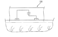
본 발명에 따른 피부패치(100)는 일 면에 형성된 부착구조에 근거하여 상기 피부에 밀착되도록 형성되고, 피부에 부착되는 경우 형상이 변형되어 밀착된 피부에 힘이 인가될 수 있다. 또한, 도 1a에 구체적으로 도시되지 아니하였으나, 상기 피부에 밀착되는 상기 피부패치(100)의 일 면으로부터 피부에 빛 및 전기적인 자극을 인가하는 발광부(120) 및 전극부(130)를 포함한다. 상기 피부패치(100)는 사용자의 피부에 밀착되어 변형에 의하여 피부의 주름을 펴고, 빛과 전기적인 자극을 이용하여 피부 재생을 촉진시킨다. 이하, 다양한 실시예에 따른 피부패치(100)의 구체적인 구조를 설명한다. The
도 2는 피부에 부착되기 위한 피부패치의 부착구조를 설명하기 위한 개념도이다. 본 발명에 따른 피부패치(100)는 상기 베이스부(101)의 일 면에 형성되어 피부에 밀착되기 위한 미세구조로 이루어지는 부착구조(110)를 구비한다. 일 실시예에 따른 미세구조는 생물학적 접착 시스템을 모사한 미세돌기를 포함한다. 2 is a conceptual diagram for explaining an attachment structure of a skin patch to be attached to the skin. The
예를 들어 상기 미세돌기는 게코(Gecko)도마뱀의 발바닥에 형성된 강모를 모사하여 형성된다. 게코 도마뱀의 발바닥에는 털 하나의 지름이 사람 머리카락 굵기의 약 1/100-1/1000 밖에 안 되는 가늘고 긴 돌기물(突起物), 즉 가시털 또는 강모가 존재하는데, 이 미세한 강모와 벽면 사이에는 '반데르발스 힘(van derWaals' force)'이 작용(전기적으로 중성인 분자들이 아주 가까운 거리에 있을 때 서로를 잡아당기는 힘)하여, 피부 표면에 약 30Ncm-2의 힘을 작용하여, 상기 피부표면에 상기 피부패치(100)가 붙어있게 되고, 털 하나하나에 작용하는 힘은 아주 작지만 복수개로 모이면 엄청난 무게를 지탱할 만한 강한 접착력이 생길 수 있다. For example, the microprotrusions are formed by mimicking the bristles formed on the sole of a gecko lizard. On the sole of a gecko lizard, there are long and thin protuberances with a single hair about 1/100-1/1000 the thickness of a human hair, that is, thorn hairs or bristles. The 'van derWaals' force' acts (the force that attracts electrically neutral molecules to each other when they are in very close proximity), and applies a force of about 30 Ncm-2 to the skin surface, The
다만, 상기 미세돌기는 사람의 피부에 부착가능한 자연모사소재로 이루어질 수 있으며, 게코 도마뱀의 발바닥에 형성된 강모의 모사형상에 한정되는 것은 아니다. 즉, 상기 부착구조(110)는 별도의 부착구조 없이 사용자의 피부에 부착가능한 형태를 이루는 자연모사소재로 이루어진다. However, the microprotrusions may be made of a natural mimic material that can be attached to human skin, and is not limited to the mimic shape of the bristles formed on the sole of the gecko lizard. That is, the
도 2의 (a) 및 (b)를 참조하면, 일 실시예에 따른 부착구조(110)는 게코(Gecko) 도마뱀의 발바닥에 존재하는 스패튤라(Spatula)형상의 미세한 섬모와 같은 형상으로 이루어지며, 각 흡착부(111)는 피부에 흡착시 흡착부(111)의 원호 형상의 홈(112)과 피부의 표면 사이에서 형성되는 부압에 의하여, 상기 피부의 표면에 상기 피부패치(100)가 고정될 수 있다. 상기 부착구조(110)는 복수의 부착유닛(110')으로 형성된다. 상기 부착유닛(110')은 9개의 흡착부(111)로 이루어질 수 있으며, 각 흡착부(111)는 상기 피부패치(100)의 일면으로부터 기 설정된 길이로 돌출되도록 형성될 수 있으나, 이에 한정되는 것은 아니며, 상기 베이스부(101)의 표면으로부터 스페튤라 형상으로 돌출되는 흡착부가 형성될 수 있다. 상기 피부패치(100)의 일 면에 형성되는 흡착부(111)의 개수는 도면에 도시된 바에 한정되는 것은 아니다. Referring to (a) and (b) of Figure 2, the
게코(gecko) 도마뱀과 같이 재질 특성에 상관없이 나노미터 수준의 미세돌기들이 모여 마이크로미터 수준의 돌기뭉치들을 형성하는 계층적 구조(hierarchical structure)를 갖는 표면의 경우 초소수성(superhydrophobic) 특성을 가지게 되며 오염을 최소화시키고 쉽게 오염물을 제거할 수 있어 접착특성을 오래 지속시킬 수 있다. 이러한 구조적 특성을 이용하면 반복적인 접촉에도 오염을 최소화하고 세척이 용이하다. In the case of a surface having a hierarchical structure, such as gecko lizard, where nanometer-level microprotrusions gather to form micrometer-level protrusions regardless of material characteristics, it has superhydrophobic properties. Since contamination is minimized and contaminants can be easily removed, adhesive properties can be maintained for a long time. By using these structural characteristics, contamination is minimized and cleaning is easy even after repeated contact.
도 2의 (b) 및 (c)를 참조하여, 피부 패치의 형상이 변형되는 경우 상기 흡착구조의 변형을 설명한다. 상기 피부패치(100)의 베이스부(110)의 재질 특성상, 상기 베이스부(110)는 일 영역에서 변형이 가능하도록 형성된다. 예를 들어, 상기 피부패치(100)의 중앙영역인 제1 영역(A1)이 변형부재 또는 외력에 의하여 변형되는 것으로 설명한다. 상기 변형에 근거하여, 상기 제1 영역(A1)을 기준으로 상기 부착유닛(110’) 사이의 거리가 증가한다. 즉 상기 제1 영역(A1)이 확장되며, 상기 제1 영역(A1)에는 상기 부착유닛(110’)이 형성되지 아니한다. With reference to FIGS. 2 (b) and (c), when the shape of the skin patch is deformed, the deformation of the adsorption structure will be described. Due to the characteristics of the material of the
또는 상기 제1 영역(A1)이 확장됨에 따라, 상기 베이스부(101)의 면적이 골고루 확장됨에 따라, 각 부착유닛(110’) 사이의 거리가 증가할 수 있다. 예를 들어, 각 부착유닛(110’)이 피부에 밀착되어 고정되고, 상기 제1 영역(A1)에 대응되도록 피부의 주름이 형성되는 경우, 상기 제1 영역(A1)이 확장되면서 주름이 펴질 수 있다. 이 경우, 상기 복수의 부착유닛(110’)은 주름을 둘러싸는 주변 피부들에 밀착되어 피부에 장력을 제공한다. Alternatively, as the first area A1 expands and the area of the base 101 evenly expands, the distance between each
이에 따라, 상기 장력에 의하여 늘어난 피부를 리프팅(lifting)할 수 있다. 또한, 상기 피부에 힘을 인가하여 주름에 장력을 제공하는 동안 상기 피부패치(100)는 표면에 밀착되어 상기 피부 표면을 덥도록 형성된다. 따라서, 경피수분손실(TEWL, TranEpidermal Water Loss)을 최소화하여 피부 수분보충을 수행할 수 있다. 여기에서 경피수분손실(TEWL)은 피부표면에서 증발되는 수분량을 의미한다. 또한 이는 피부장벽 기능의 이상을 나타내는 지표가 될 수 있으며, 과도한 수분의 손실은 피부건조 증상을 나타낼 수 있다. Accordingly, it is possible to lift the skin stretched by the tension. In addition, while applying a force to the skin to provide tension to the wrinkles, the
본 발명의 피부패치는 상기 부착구조(110)를 포함하는 상기 베이스부(101)에 형성되어 피부표면에 빛을 제공하는 발광부(120) 및 상기 피부에 미세전류를 흘리도록 형성되는 전극부(130)로 이루어지는 피부 자극부를 더 포함한다. 도 3a 내지 도 3b는 피부 자극부의 구조를 설명하기 위한 개념도이다. The skin patch of the present invention is formed on the
도 3a를 참조하면, 상기 피부 자극부는 상기 부착구조(110)가 형성된 상기 피부패치(100)의 일 면과 실질적으로 동일한 면에 형성된다. 예를 들어, 상기 피부 자극부는 상기 부착유닛(110’)의 사이에 배치되거나, 상기 각 흡착부(111) 사이에 배치될 수 있다.Referring to FIG. 3A , the skin stimulation part is formed on substantially the same surface as the one surface of the
도 3b를 참조하면, 상기 발광부(120)는 복수의 LED 칩을 포함하며, 상기 피부패치(100)에 내장되어 빛을 방출한다. 상기 복수의 LED 칩은 상기 베이스부(101') 상에 기 설정된 배열로 배치된다. Referring to FIG. 3B , the
상기 LED 칩은 사용자의 설정 또는 제어명령에 근거하여 특정 파장의 빛을 방출하도록 구동된다. 예를 들어, 상기 LED칩은 약 630nm의 제1 파장의 빛, 약 830nm의 제2 파장의 빛 및 약 415nm의 제3 파장의 빛을 선택적으로 방출할 수 있도록, 세 가지의 LED칩으로 구성되어 있다.The LED chip is driven to emit light of a specific wavelength based on a user's setting or control command. For example, the LED chip is composed of three LED chips to selectively emit light of a first wavelength of about 630 nm, light of a second wavelength of about 830 nm, and light of a third wavelength of about 415 nm. have.
상기 제1 파장의 빛에 의하여 피부의 콜라겐 합성을 촉진하거나 MMP(metalloproteinase)의 감소를 촉진하여 피부재활에 영향을 미칠 수 있고, 상기 제2 파장의 빛에 의하여 피부재활과 동시에 상처치료에 좋은 효과가 있으며, 제3 파장의 빛에 의하여 아토피성 습진 및 여드름 염증을 완화시킬 수 있다.The first wavelength of light promotes collagen synthesis in the skin or promotes reduction of MMP (metalloproteinase), thereby affecting skin rehabilitation. There is, it is possible to relieve atopic eczema and acne inflammation by the light of the third wavelength.
상기 발광부(120)는 상기 복수의 LED 칩에 전류를 공급하기 위한 전도성 코팅층을 포함할 수 있다. 상기 전도성 코팅층은 실버, 구리, 니켈, 알루미늄, 카본 중 어느 하나의 재질로 이루어지는 것이 바람직하고, 상기 재료들 중 어느 하나 이상으로 구성된 도전성 잉크를 회로기판에 인쇄가공하거나, 도전성 금속을 에칭방식에 의하여 일정한 패턴을 가공한 플렉서블 회로기판으로 형성될 수 있다. The
상기 발광부(120)는 상기 흡착부(111)에 의하여 상기 피부패치가 상기 피부의 표면에 부착되어 있는 동안, 상기 제1 내지 제3 파장 중 어느 하나의 파장을 갖는 빛을 방출하여 피부를 자극한다. The
또한 본 발명에 따른 피부패치(100)는 상기 베이스부(101)의 내부에 장착된 전극부(130)를 더 포함한다. 상기 전극부(130)는 상기 피부에 미세전류를 흘려 피부를 구성하는 세포를 자극한다. 보다 구체적으로 상기 피부의 손상된 조직이나 세포에 미세전류를 흘려 ATP, 단백질 등을 생산하고, 세포들의 이온교환, 영양분 흡수를 촉진시킨다. 이에 따라 세포의 항상성이 복구되고 콜라겐의 생성이 증가할 수 있다. In addition, the
상기 전극부(130)는 상기 베이스부(101)의 일 면에 기 설정된 패턴으로 박힌 상태로 형성된다. 도 3c는 도 3a의 일 영역을 A-A를 따라 절단한 단면도이다. 도 3c를 참조하면, 상기 전극부(130)는 피부 표면과 직접 접촉하는 애노드 및 캐쏘드와 연결된, 프린트된, 얇은 마이크로 배터리를 포함할 수 있다. 전극간의 전위차는 상기 애노드로부터 피부를 통과하여 캐쏘드로 흐르는 전류를 발생시킨다. 이는 다시 피부 표면 상의 대전된 활성미용 또는 제약성분에 기전력을 발생시킬 수 있다. The
본 발명에 따른 피부패치는 사용자의 피부 상태에 따라 형상이 변하도록 힘을 제공하는 인장부를 더 포함한다. 이하, 상기 인장부의 구성을 설명한다.The skin patch according to the present invention further includes a tension part that provides a force to change the shape according to the skin condition of the user. Hereinafter, the configuration of the tension part will be described.
도 4a 내지 도 4c는 다양한 실시예에 따른 인장부를 설명하기 위한 개념도이다. 본 발명에 따른 인장부는 사용자에 의하여 인가되는 외력 또는 제어명령에 근거하여 상기 피부패치(100)를 변형시키도록 형성된다. 상기 제어부는 상기 감지부에 의하여 감지된 피부상태에 근거하여 상기 인장부를 변형시키기 위한 전기신호를 형성할 수 있다. 4A to 4C are conceptual views for explaining a tension part according to various embodiments. The tension part according to the present invention is formed to deform the
도 4a를 참조하면, 상기 피부패치(100)는 상기 베이스부(101)의 가장자리에 제1 인장부(141)가 형성된다. 상기 제1 인장부(141)는 상기 가장자리 영역에 형성되고 전기신호에 근거하여 길이가 증감하도록 형성되는 변형센서로 이루어질 수 있다. 상기 변형센서는 형상의 변형이 감지되면 전기신호를 형성하거나, 인가되는 전기신호에 따라 형상이 변형된다.Referring to FIG. 4A , in the
예를 들어, 상기 제1 인장부(141)는 상기 전기신호에 근거하여 길이가 변형되고, 상기 제1 인장부(141)의 변형에 근거하여 상기 피부패치(100)의 전체 면적이 확장된다. 이에 따라 상기 피부에 부착되어있던 피부패치(100)의 확장에 따라 상기 피부패치(100)가 부착되어있는 피부의 일 영역도 확장되므로 주름의 감소 효과가 발생할 수 있다.For example, the length of the first
도 4b를 참조하면, 상기 피부패치(100)는 제1 및 제2 베이스부재(101a, 101b)를 포함하고, 상기 제1 및 제2 베이스부재(101a, 101b)를 연결하는 제2 인장부(142)를 포함한다. Referring to FIG. 4B , the
상기 제 2 인장부(142)는 상기 피부패치(100)의 상기 피부에 밀착되는 일 면에 형성될 수 있으나, 이에 한정되는 것은 아니며, 상기 피부패치(100)가 피부에 부착되었을 때 노출되는 영역에 형성될 수 있다. 도 4b의 (a) 및 (b)를 참조하면, 상기 제1 및 제2 베이스 부재(101a 101b)는 서로 인접하도록 상기 제2 인장부(142)에 의하여 결합한다. The
도 4b의 (c)를 참조하면, 상기 제2 인장부(142)는 전기신호에 근거하여 길이가 변형되는 변형센서로 이루어질 수 있다. 상기 제2 인장부(142)는 외력 또는 제어명령에 근거하여 길이가 길어질 수 있으며, 상기 제2 인장부(142)의 길이가 길어짐에 따라 상기 제1 및 제2 베이스 부재(101a, 101b) 사이의 거리가 멀어진다. Referring to (c) of FIG. 4B , the
따라서, 상기 제1 및 제2 베이스 부재(101a, 101b) 사이에 위치하는 피부에 장력이 적용되고 피부의 주름이 펴지게된다. Accordingly, tension is applied to the skin positioned between the first and
도면에 구체적으로 도시되지 아니하였으나, 상기 제2 인장부(142) 상에는 상기 피부패치(100)를 피부에 부착하기 위한 흡착부 등이 형성되지 아니할 수 있다. 본 실시예에 따르면 피부의 주름이 형성된 영역이 상기 제1 및 제2 베이스부(101a, 101b) 사이에 위치하도록 부착하고, 상기 제2 인장부(142)를 제어하여 주름을 개선시킬 수 있다. Although not specifically shown in the drawings, an adsorption part for attaching the
도 4c를 참조하면, 상기 피부패치(100)는 물리적인 힘에 의하여 상기 피부패치(100)가 증가하도록 이루어지는 제3 인장부(143)를 포함한다. 상기 제3 인장부(143)는 제1 및 제2 부재(143a, 143b) 및 탄성부(143c)를 포함할 수 있다. Referring to FIG. 4C , the
상기 제1 및 제2 부재(143a, 143b)는 서로 마주보도록 상기 피부패치(100)의 베이스부(101)의 가장자리를 따라 형성될 수 있다. 상기 제1 및 제2 부재(143a, 143b)는 사용자의 외력에 의하여 이동 가능하도록 형성되며, 상기 베이스부(101)d의 타면 상에서 돌출되도록 형성된다.The first and
상기 탄성부(143c)는 상기 제1 및 제2 부재(143a, 143b)를 탄성 지지하도록 형성될 수 있으며, 상기 탄성부(143c)의 탄성력은 상기 베이스부(101)의 재질에 의하여 설정될 수 있다. The
상기 피부패치(100)가 피부에 부착된 상태에서 상기 제1 및 제2 부재(143a, 143b)에 부착된 상태에서, 사용자의 외력에 의하여 상기 제1 및 제2 부재(143a, 143b)가 서로 멀어지게 되어 상기 피부패치(100)가 확장되면, 이에 따라 피부에 형성되는 주름 등이 펴질 수 있다. 상기 피부패치(100)는 상기 베이스부(101)의 재질 상의 성질에 의하여 상기 제1 및 제2 부재(143a, 142b)가 멀어진 상태를 유지할 수 있으며 상기 탄성부(143c)의 탄성력에 의하여 상기 피부패치(100)가 피부로부터 분리되면 상기 피부패치(100)의 형상이 복귀될 수 있다. In a state in which the
도 5a 및 도 5b는 다른 실시예에 따른 자극부의 배치구조를 설명하기 위한 개념도이다.5A and 5B are conceptual views for explaining an arrangement structure of a magnetic pole unit according to another embodiment.
도 5a를 참조하면, 상기 전극부(130)는 상기 피부패치(100)의 중앙영역에 형성되고, 상기 부착유닛(110')은 상기 전극부(130)를 둘러싸도록 상기 피부패치(100) 상에 형성된다. 즉, 상기 전극부(130)는 상기 부착유닛(110')과 중첩되지 아니하며 상기 전극부(130)는 상기 피부에 직접적으로 접촉할 수 있다. 이에 따라 상기 전극부(130)에서 발생하는 미세전류가 피부에 보다 효과적으로 전달될 수 있다. Referring to FIG. 5A , the
또한, 상기 베이스부가 이동 가능한 복수의 부재로 이루어지는 경우 상기 전극부(130) 또한 복수의 전극부재로 이루어질 수 있다. 본 실시예에 따른 피부패치(100)의 발광부(120)는 상기 부착유닛(110') 사이에 배치될 수 있다.In addition, when the base part is made of a plurality of movable members, the
도 5b를 참조하면, 상기 피부패치(100)는 제1 내지 제3 베이스부재(101a, 101b, 101c)를 포함하고, 상기 제3 베이스 부재(101c)는 전기신호에 근거하여 길이가 변하는 변형센서를 더 포함할 수 잇다. Referring to FIG. 5B , the
상기 제3 베이스 부재(101c)에 근거하여 상기 제1 및 제2 베이스부재(101a, 101b) 사이의 거리가 증감할 수 있다. 상기 제1 및 제2 베이스부재(101a, 101b)에 상기 복수의 부착유닛(110')이 형성된다. 이에 따라, 상기 피부패치(100)가 부착된 상태에서 상기 제3 베이스 부재(101c)가 변형되면, 상기 제3 베이스 부재(101c)의 변형에 근거하여 상기 제1 및 제2 베이스부재(101a, 101b) 사이의 피부가 늘어나게 된다. The distance between the first and
상기 제3 베이스 부재(101c) 상에는 상기 전극부(130)가 형성된다. 즉, 상기 전극부(130)는 상기 부착유닛(110')과 중첩되지 아니하여 상기 피부에 직접적으로 접촉될 수 있는바, 미세전류를 보다 효과적으로 피부에 전달할 수 있다. The
도 6a 및 도 6b는 접힘구조를 포함하는 피부패치를 설명하기 위한 개념도이다.6A and 6B are conceptual views for explaining a skin patch including a folded structure.
도 6a를 참조하면, 상기 피부패치(100)의 베이스 부재(101)의 타면에는 형성되는 접힘 가이드부(160)를 더 포함한다. 상기 접힘 가이드부(160)는 사용자의 외력에 의하여 상기 피부패치(100)의 일 영역이 다른 영역과 중첩되는 상태를 유지하도록, 일 방향으로 이루어지는 홈 형상으로 형성될 수 있다.Referring to FIG. 6A , it further includes a
즉, 상기 피부패치(100)가 피부에 부착된 상태에서 상기 접힘 가이드부를 통하여 상기 피부패치(100)가 중첩되는 상태로 유지되면, 상기 자극부 및 상기 부착구조가 외부로 노출된다. 상기 접힘 가이드부(160)의 형상은 도면에 도시된 바에 한정되는 것은 아니며, 상기 피부패치(100)의 형상 및 상기 피부패치(100)가 부착되는 피부의 부위에 따라 다르게 형성될 수 있다. That is, when the
사용자는 상기 접힘 가이드부(160)를 이용하여 상기 피부패치(100)의 크기를 조절할 수 있으므로, 사용자가 원하는 피부의 영역에 상기 피부패치를 부착할 수 있다. Since the user can adjust the size of the
도 6b를 참조하면, 상기 피부패치(100)의 타면에는 결합부(170)가 형성된다. 상기 결합부(170)는 상기 게코(gecko) 도마뱀의 발바닥에 형성된 강모를 모사하여 형성된 복수의 미세돌기들을 포함한다. 상기 미세돌기들이 서로 마주보도록 배치되면 서로 결합되도록 유지될 수 있다. 이에 따라, 상기 피부패치(100)의 상기 타면끼리 마주보도록 결합하면 상기 피부패치를 접어서 사용할 수 있다. Referring to FIG. 6B , a
이에 따라 사용자는 피부패치를 어느 영역으로든 접어서 원하는 피부 영역에 맞도록 크기를 조절할 수 있다. Accordingly, the user can fold the skin patch into any area and adjust the size to fit a desired skin area.
도 7은 또 다른 실시예에 따른 피부패치의 구조를 설명하기 위한 개념도이다. 본 실시예에 따른 피부패치는 지지부(181) 및 상기 지지부(181)에 고정되는 한 쌍의 패치부(182)를 포함한다. 상기 지지부(181)에 형성되는 패치부(182)의 개수는 이에 한정되는 것은 아니다.7 is a conceptual diagram for explaining the structure of a skin patch according to another embodiment. The skin patch according to the present embodiment includes a
상기 지지부(181)는 일 방향으로 연장된 형상을 이루며, 상기 지지부(181)는 외력 또는 제어명령에 근거하여 길이가 변형되도록 이루어질 수 있다. 상기 지지부(181)는 상기 패치부(182)가 고정될 수 있는 수납부(183)를 구비한다.The
도면에 도시되지 아니하였으나, 상기 패치부(182)의 일 면 상에는 상기 피부에 부착 가능하도록 형성되는 부착구조(110), 상기 피부에 광을 조사하도록 이루어지는 발광부(120) 및 상기 미세전류를 흘리도록 구성되는 전극부(130)를 더 포함할 수 있으며, 중복되는 설명은 생략한다. Although not shown in the drawing, on one surface of the
사용자는 상기 패치부(182)를 피부에 부착하여 사용할 수 있으며, 피부에 장력을 제공할 필요가 있는 경우, 상기 지지부(181)에 상기 패치부(182)를 고정시켜 피부가 늘어나도록 힘을 제공할 수 있다. The user can use the
상기와 같이 설명된 피부패치는 상기 설명된 실시예들의 구성과 방법이 한정되게 적용될 수 있는 것이 아니라, 상기 실시예들은 다양한 변형이 이루어질 수 있도록 각 실시예들의 전부 또는 일부가 선택적으로 조합되어 구성될 수도 있다.In the skin patch described above, the configuration and method of the above-described embodiments are not limitedly applicable, but all or part of each embodiment can be selectively combined so that various modifications can be made. may be
Claims (20)
상기 베이스부의 일면에 형성되며 피부에 부착되도록 미세섬모구조로 이루어지는 부착구조;
상기 베이스부의 일면에 형성되어 피부에 빛 및 미세전류 중 적어도 하나를 제공하는 자극부; 및
상기 피부에 부착된 상태에서, 상기 베이스부를 변형시켜 피부에 물리력을 제공하는 인장부;를 포함하는 것으로,
상기 베이스부는 서로 분리되는 제1 및 제2 베이스 부재를 포함하고,
상기 인장부는 상기 제1 및 제2 베이스 부재 사이에 형성되며,
상기 인장부의 변형에 의하여 상기 제1 및 제2 베이스 부재 사이의 거리가 멀어지고,
상기 인장부는 전기신호에 근거하여 형상이 변형되는 변형센서로 이루어지는 것을 특징으로 하는 피부패치.a base portion made of a deformable elastic member;
an attachment structure formed on one surface of the base part and formed of a microcilia structure so as to be attached to the skin;
a stimulation unit formed on one surface of the base unit to provide at least one of light and microcurrent to the skin; and
In a state attached to the skin, a tension part for providing a physical force to the skin by deforming the base part;
The base portion includes first and second base members separated from each other,
The tension part is formed between the first and second base members,
The distance between the first and second base members is increased by the deformation of the tension part,
The tensile part is a skin patch, characterized in that made of a deformation sensor that is deformed in shape based on an electrical signal.
상기 자극부는 기 설정된 파장의 빛을 방출하도록 상기 베이스부의 일 면 상에 기 설정된 배열로 배치되는 복수의 LED 유닛; 및
상기 인장부 상기 피부의 표면에 상기 미세전류를 흘리도록 형성되는 전극부를 포함하는 것을 특징으로 하는 피부패치.According to claim 1,
a plurality of LED units arranged in a preset arrangement on one surface of the base part to emit light of a preset wavelength; and
The skin patch, characterized in that it comprises an electrode portion formed to flow the micro-current to the surface of the skin in the tension portion.
상기 인장부는 상기 베이스부의 가장자리에 형성되는 것을 특징으로 하는 피부패치.According to claim 1,
The tensile portion is a skin patch, characterized in that formed on the edge of the base portion.
상기 인장부는 상기 베이스부의 면적을 변형시키기 위하여 전기신호에 근거하여 길이의 가변이 가능한 변형센서로 이루어지는 것을 특징으로 하는 피부패치.6. The method of claim 5,
The tensile part is a skin patch, characterized in that it is made of a deformation sensor that can change the length based on an electric signal to deform the area of the base part.
상기 인장부는 외력에 의하여 벌어지는 복수의 인장부재 및 상기 복수의 인장부재 사이를 탄성지지하는 탄성부재를 포함하는 것을 특징으로 하는 피부패치.6. The method of claim 5,
The tension part skin patch, characterized in that it comprises a plurality of tension members spread by an external force and an elastic member for elastically supporting between the plurality of tension members.
상기 인장부재는 상기 베이스부의 타면에 돌출되도록 형성되는 것을 특징으로 하는 피부패치. 8. The method of claim 7,
The tension member is a skin patch, characterized in that formed to protrude from the other surface of the base part.
상기 부착구조는 피부의 표면에 부압을 형성하는 홈을 포함하는 복수의 흡착부를 포함하며, 기 설정된 패턴으로 나열되는 복수의 흡착유닛으로 이루어지고,
상기 인장부는 상기 흡착유닛 사이에 형성되어 상기 흡착유닛 사이를 확장하는 것을 특징으로 하는 피부패치.According to claim 1,
The attachment structure includes a plurality of adsorption units including grooves for forming a negative pressure on the surface of the skin, and consists of a plurality of adsorption units arranged in a preset pattern,
The tensile part is formed between the adsorption units, and the skin patch, characterized in that it extends between the adsorption units.
상기 베이스부에 형성되어, 상기 베이스부가 접힘가능하도록 형성되는 가이드부를 더 포함하고,
상기 가이드부는 상기 베이스부의 타면에 일 방향으로 이루어지는 홈 형상으로 형성되고,
상기 가이드부는 상기 베이스부의 타면 상에 형성되며, 상기 타면이 중첩되는 경우 결합가능하도록 이루어지는 복수의 미세섬모로 이루어지는 것을 특징으로 하는 피부패치.According to claim 1,
It is formed on the base portion, further comprising a guide portion formed so that the base portion is foldable,
The guide part is formed in a groove shape made in one direction on the other surface of the base part,
The guide part is formed on the other surface of the base part, and the skin patch, characterized in that it consists of a plurality of microcilia formed to be coupled when the other surface overlaps.
Priority Applications (2)
| Application Number | Priority Date | Filing Date | Title |
|---|---|---|---|
| KR1020140131805A KR102338552B1 (en) | 2014-09-30 | 2014-09-30 | Dermal patch and method for skin rejuvenation |
| PCT/KR2014/012992 WO2016052818A1 (en) | 2014-09-30 | 2014-12-29 | Dermal patch and method for skin rejuvenation |
Applications Claiming Priority (1)
| Application Number | Priority Date | Filing Date | Title |
|---|---|---|---|
| KR1020140131805A KR102338552B1 (en) | 2014-09-30 | 2014-09-30 | Dermal patch and method for skin rejuvenation |
Publications (2)
| Publication Number | Publication Date |
|---|---|
| KR20160038567A KR20160038567A (en) | 2016-04-07 |
| KR102338552B1 true KR102338552B1 (en) | 2021-12-13 |
Family
ID=55630828
Family Applications (1)
| Application Number | Title | Priority Date | Filing Date |
|---|---|---|---|
| KR1020140131805A Active KR102338552B1 (en) | 2014-09-30 | 2014-09-30 | Dermal patch and method for skin rejuvenation |
Country Status (2)
| Country | Link |
|---|---|
| KR (1) | KR102338552B1 (en) |
| WO (1) | WO2016052818A1 (en) |
Cited By (2)
| Publication number | Priority date | Publication date | Assignee | Title |
|---|---|---|---|---|
| KR20230099247A (en) | 2021-12-27 | 2023-07-04 | 주식회사 페이지원 | LED wearable device capable of monitoring wound care |
| KR102750436B1 (en) * | 2024-02-29 | 2025-01-03 | 서빛나 | Multi-wavelength high-frequency energy output device |
Families Citing this family (30)
| Publication number | Priority date | Publication date | Assignee | Title |
|---|---|---|---|---|
| US8048089B2 (en) | 2005-12-30 | 2011-11-01 | Edge Systems Corporation | Apparatus and methods for treating the skin |
| US9566088B2 (en) | 2006-03-29 | 2017-02-14 | Edge Systems Llc | Devices, systems and methods for treating the skin |
| WO2009088884A1 (en) | 2008-01-04 | 2009-07-16 | Edge Systems Corporation | Apparatus and method for treating the skin |
| WO2009097451A1 (en) | 2008-01-29 | 2009-08-06 | Edge Systems Corporation | Apparatus and method for treating the skin |
| EP3437575B1 (en) | 2013-03-15 | 2021-04-21 | Edge Systems LLC | Devices and systems for treating the skin |
| WO2016106396A1 (en) | 2014-12-23 | 2016-06-30 | Edge Systems Llc | Devices and methods for treating the skin using a rollerball or a wicking member |
| US10179229B2 (en) | 2014-12-23 | 2019-01-15 | Edge Systems Llc | Devices and methods for treating the skin using a porous member |
| KR102610589B1 (en) * | 2016-08-04 | 2023-12-07 | 삼성전자주식회사 | Method and apparatus for estimating skin condition |
| KR102182169B1 (en) | 2016-10-06 | 2020-11-24 | 엘지전자 주식회사 | Skin care device |
| US11241563B2 (en) | 2016-12-22 | 2022-02-08 | Johnson & Johnson Consumer Inc. | Microneedle arrays and methods for making and using |
| KR200497047Y1 (en) * | 2018-02-28 | 2023-07-10 | 주식회사 에코웰 | LED beauty treatment patch |
| WO2019219887A1 (en) | 2018-05-18 | 2019-11-21 | Koninklijke Philips N.V. | Vacuum patch |
| EP3813792A2 (en) | 2018-06-29 | 2021-05-05 | Johnson & Johnson Consumer Inc. | Three-dimensional microfluidics devices for the delivery of actives |
| CN108992792A (en) * | 2018-09-17 | 2018-12-14 | 深圳市名家汇科技股份有限公司 | A kind of red-light LED mask |
| US10898138B2 (en) * | 2018-12-18 | 2021-01-26 | Amorepacific Corporation | Flexible patch including a plurality of through holes which can be adhered to skin and method for manufacturing the same |
| SG11202107772YA (en) * | 2019-01-24 | 2021-08-30 | Otsuka Pharma Co Ltd | Elastic wearable sensor |
| KR20200133652A (en) * | 2019-05-20 | 2020-11-30 | 주식회사 노드 | Apparatus for dark circle care and method for controlling the same |
| US11291474B2 (en) | 2020-01-06 | 2022-04-05 | Ed F. Nicolas | Skin treatment tool applicator tip |
| KR102645634B1 (en) | 2020-10-30 | 2024-03-11 | 한성대학교 산학협력단 | A patch with negative poisson's ratio |
| KR102242158B1 (en) | 2021-01-18 | 2021-04-21 | 주식회사 뉴트리어드바이저 | Outdoor patch for uv protection |
| USD1065551S1 (en) | 2021-09-10 | 2025-03-04 | Hydrafacial Llc | Skin treatment device |
| USD1016615S1 (en) | 2021-09-10 | 2024-03-05 | Hydrafacial Llc | Container for a skin treatment device |
| CA3231401A1 (en) | 2021-09-10 | 2023-03-16 | Hydrafacial Llc | Devices, systems and methods for treating the skin |
| USD1042807S1 (en) | 2021-10-11 | 2024-09-17 | Hydrafacial Llc | Skin treatment tip |
| USD1116120S1 (en) | 2021-10-11 | 2026-03-03 | Hydrafacial Llc | Skin treatment device |
| FR3130553B1 (en) * | 2021-12-21 | 2024-11-29 | Oreal | Device for stretching a patch, in particular a cosmetic patch |
| EP4452157A1 (en) * | 2021-12-21 | 2024-10-30 | L'oreal | Device for stretching a patch, notably a cosmetic patch |
| KR102769974B1 (en) * | 2022-01-18 | 2025-02-21 | 한국광기술원 | Salivary gland and lymph gland complex stimulation device |
| USD1112778S1 (en) | 2022-03-04 | 2026-02-10 | Hydrafacial Llc | Light therapy device for skin care |
| USD1084369S1 (en) | 2023-02-10 | 2025-07-15 | Hydrafacial Llc | Skin treatment tip |
Family Cites Families (8)
| Publication number | Priority date | Publication date | Assignee | Title |
|---|---|---|---|---|
| ATE291893T1 (en) * | 1996-05-10 | 2005-04-15 | Wallace J Beaudry | NASAL EPIDERMAL DELIVERY MECHANISM |
| US8734421B2 (en) * | 2003-06-30 | 2014-05-27 | Johnson & Johnson Consumer Companies, Inc. | Methods of treating pores on the skin with electricity |
| US7780810B2 (en) * | 2007-07-16 | 2010-08-24 | RD & L Unique Products, LLC | Adhesion device for applying and releasing biomimetic microstructure adhesive from a contact surface |
| EP2384228A4 (en) * | 2009-01-05 | 2012-06-13 | Plextronics Inc | ILLUMINATION SYSTEM FOR PHOTOTHERAPY WITH ORGANIC LIGHT EMITTING DIODES |
| KR101007788B1 (en) * | 2009-05-27 | 2011-01-28 | (주)경원유글로브 | Non-contact metal electrode patch and biosignal measuring device for biosignal measurement |
| KR101190665B1 (en) * | 2010-09-14 | 2012-10-15 | 이동명 | Adhesive articular protecter |
| US9433781B2 (en) * | 2010-12-03 | 2016-09-06 | Syneron Medical Ltd. | Method and apparatus for improving electrode-skin contact |
| US8954155B2 (en) * | 2011-09-19 | 2015-02-10 | Biotalk Technologies Inc | Apparatus and method for rejuvenating skin |
-
2014
- 2014-09-30 KR KR1020140131805A patent/KR102338552B1/en active Active
- 2014-12-29 WO PCT/KR2014/012992 patent/WO2016052818A1/en not_active Ceased
Cited By (2)
| Publication number | Priority date | Publication date | Assignee | Title |
|---|---|---|---|---|
| KR20230099247A (en) | 2021-12-27 | 2023-07-04 | 주식회사 페이지원 | LED wearable device capable of monitoring wound care |
| KR102750436B1 (en) * | 2024-02-29 | 2025-01-03 | 서빛나 | Multi-wavelength high-frequency energy output device |
Also Published As
| Publication number | Publication date |
|---|---|
| WO2016052818A1 (en) | 2016-04-07 |
| KR20160038567A (en) | 2016-04-07 |
Similar Documents
| Publication | Publication Date | Title |
|---|---|---|
| KR102338552B1 (en) | Dermal patch and method for skin rejuvenation | |
| JP7083184B2 (en) | Skin beauty equipment | |
| US12186580B2 (en) | Patch-type skincare device | |
| CN205073521U (en) | Electro photoluminescence device for abdominal muscle | |
| US20220257971A1 (en) | Facial beauty device and mask sheet used therefor | |
| KR102275479B1 (en) | Iontophoretic device with independent current management | |
| US11684762B2 (en) | Energy self-sufficient real time bio-signal monitoring and nutrient delivery system based on salinity gradient power generation | |
| EP3085410A1 (en) | Skin treatment device using needle | |
| TW201707749A (en) | Muscular electric stimulation device | |
| CN106473907A (en) | Three-dimensional negative pressure complex stimuluies device module for the skin function of matching type complex stimuluies | |
| KR200497047Y1 (en) | LED beauty treatment patch | |
| KR20160038566A (en) | Skin permeation apparatus and method | |
| KR102425646B1 (en) | Cosmetic Absorption Promoting Device of Hands-free Type and Driving Method Thereof | |
| AU2002360718B2 (en) | Reservoir housing having a conductive region integrally formed therein | |
| US20180036526A1 (en) | Electrical stimulation device | |
| US9901735B1 (en) | Ancillary device for electrical stimulation device and electrical stimulation device | |
| KR102046466B1 (en) | Rechargeable handy type skin beauty device | |
| Xu et al. | A biomimetic nociceptor based on a vertical multigate, multichannel neuromorphic transistor | |
| KR20170138844A (en) | Iontophoresis device, the method of iontophoresis and a skin care device including the same | |
| KR101566796B1 (en) | Electrical stimulation device | |
| US20210290954A1 (en) | Wrinkle Repair System | |
| CN222092332U (en) | Skin treatment device and conductive sheet | |
| KR20080001228U (en) | Electrical beauty mask set | |
| CN212913905U (en) | Flexible electronic film body applied to human body | |
| KR20190062643A (en) | Glasses type apparatus for skim care |
Legal Events
| Date | Code | Title | Description |
|---|---|---|---|
| PA0109 | Patent application |
St.27 status event code: A-0-1-A10-A12-nap-PA0109 |
|
| PN2301 | Change of applicant |
St.27 status event code: A-3-3-R10-R13-asn-PN2301 St.27 status event code: A-3-3-R10-R11-asn-PN2301 |
|
| PG1501 | Laying open of application |
St.27 status event code: A-1-1-Q10-Q12-nap-PG1501 |
|
| PN2301 | Change of applicant |
St.27 status event code: A-3-3-R10-R13-asn-PN2301 St.27 status event code: A-3-3-R10-R11-asn-PN2301 |
|
| P22-X000 | Classification modified |
St.27 status event code: A-2-2-P10-P22-nap-X000 |
|
| A201 | Request for examination | ||
| AMND | Amendment | ||
| E13-X000 | Pre-grant limitation requested |
St.27 status event code: A-2-3-E10-E13-lim-X000 |
|
| P11-X000 | Amendment of application requested |
St.27 status event code: A-2-2-P10-P11-nap-X000 |
|
| P13-X000 | Application amended |
St.27 status event code: A-2-2-P10-P13-nap-X000 |
|
| PA0201 | Request for examination |
St.27 status event code: A-1-2-D10-D11-exm-PA0201 |
|
| PN2301 | Change of applicant |
St.27 status event code: A-3-3-R10-R13-asn-PN2301 St.27 status event code: A-3-3-R10-R11-asn-PN2301 |
|
| E902 | Notification of reason for refusal | ||
| PE0902 | Notice of grounds for rejection |
St.27 status event code: A-1-2-D10-D21-exm-PE0902 |
|
| AMND | Amendment | ||
| E13-X000 | Pre-grant limitation requested |
St.27 status event code: A-2-3-E10-E13-lim-X000 |
|
| P11-X000 | Amendment of application requested |
St.27 status event code: A-2-2-P10-P11-nap-X000 |
|
| P13-X000 | Application amended |
St.27 status event code: A-2-2-P10-P13-nap-X000 |
|
| E601 | Decision to refuse application | ||
| PE0601 | Decision on rejection of patent |
St.27 status event code: N-2-6-B10-B15-exm-PE0601 |
|
| X091 | Application refused [patent] | ||
| AMND | Amendment | ||
| P11-X000 | Amendment of application requested |
St.27 status event code: A-2-2-P10-P11-nap-X000 |
|
| P13-X000 | Application amended |
St.27 status event code: A-2-2-P10-P13-nap-X000 |
|
| PX0901 | Re-examination |
St.27 status event code: A-2-3-E10-E12-rex-PX0901 |
|
| PX0701 | Decision of registration after re-examination |
St.27 status event code: A-3-4-F10-F13-rex-PX0701 |
|
| X701 | Decision to grant (after re-examination) | ||
| GRNT | Written decision to grant | ||
| PR0701 | Registration of establishment |
St.27 status event code: A-2-4-F10-F11-exm-PR0701 |
|
| PR1002 | Payment of registration fee |
St.27 status event code: A-2-2-U10-U11-oth-PR1002 Fee payment year number: 1 |
|
| PG1601 | Publication of registration |
St.27 status event code: A-4-4-Q10-Q13-nap-PG1601 |
|
| PN2301 | Change of applicant |
St.27 status event code: A-5-5-R10-R13-asn-PN2301 St.27 status event code: A-5-5-R10-R11-asn-PN2301 |
|
| PR1001 | Payment of annual fee |
St.27 status event code: A-4-4-U10-U11-oth-PR1001 Fee payment year number: 4 |
|
| PR1001 | Payment of annual fee |
St.27 status event code: A-4-4-U10-U11-oth-PR1001 Fee payment year number: 5 |
|
| U11 | Full renewal or maintenance fee paid |
Free format text: ST27 STATUS EVENT CODE: A-4-4-U10-U11-OTH-PR1001 (AS PROVIDED BY THE NATIONAL OFFICE) Year of fee payment: 5 |
|
| R18 | Changes to party contact information recorded |
Free format text: ST27 STATUS EVENT CODE: A-5-5-R10-R18-OTH-X000 (AS PROVIDED BY THE NATIONAL OFFICE) |
|
| R18-X000 | Changes to party contact information recorded |
St.27 status event code: A-5-5-R10-R18-oth-X000 |