KR102244427B1 - Lighting device - Google Patents
Lighting device Download PDFInfo
- Publication number
- KR102244427B1 KR102244427B1 KR1020140067055A KR20140067055A KR102244427B1 KR 102244427 B1 KR102244427 B1 KR 102244427B1 KR 1020140067055 A KR1020140067055 A KR 1020140067055A KR 20140067055 A KR20140067055 A KR 20140067055A KR 102244427 B1 KR102244427 B1 KR 102244427B1
- Authority
- KR
- South Korea
- Prior art keywords
- unit
- light
- pattern
- lighting device
- light source
- Prior art date
Links
Images


Classifications
-
- F—MECHANICAL ENGINEERING; LIGHTING; HEATING; WEAPONS; BLASTING
- F21—LIGHTING
- F21S—NON-PORTABLE LIGHTING DEVICES; SYSTEMS THEREOF; VEHICLE LIGHTING DEVICES SPECIALLY ADAPTED FOR VEHICLE EXTERIORS
- F21S10/00—Lighting devices or systems producing a varying lighting effect
- F21S10/005—Lighting devices or systems producing a varying lighting effect using light guides
-
- F—MECHANICAL ENGINEERING; LIGHTING; HEATING; WEAPONS; BLASTING
- F21—LIGHTING
- F21S—NON-PORTABLE LIGHTING DEVICES; SYSTEMS THEREOF; VEHICLE LIGHTING DEVICES SPECIALLY ADAPTED FOR VEHICLE EXTERIORS
- F21S43/00—Signalling devices specially adapted for vehicle exteriors, e.g. brake lamps, direction indicator lights or reversing lights
- F21S43/20—Signalling devices specially adapted for vehicle exteriors, e.g. brake lamps, direction indicator lights or reversing lights characterised by refractors, transparent cover plates, light guides or filters
- F21S43/235—Light guides
- F21S43/236—Light guides characterised by the shape of the light guide
- F21S43/239—Light guides characterised by the shape of the light guide plate-shaped
-
- F—MECHANICAL ENGINEERING; LIGHTING; HEATING; WEAPONS; BLASTING
- F21—LIGHTING
- F21S—NON-PORTABLE LIGHTING DEVICES; SYSTEMS THEREOF; VEHICLE LIGHTING DEVICES SPECIALLY ADAPTED FOR VEHICLE EXTERIORS
- F21S43/00—Signalling devices specially adapted for vehicle exteriors, e.g. brake lamps, direction indicator lights or reversing lights
- F21S43/20—Signalling devices specially adapted for vehicle exteriors, e.g. brake lamps, direction indicator lights or reversing lights characterised by refractors, transparent cover plates, light guides or filters
- F21S43/235—Light guides
- F21S43/242—Light guides characterised by the emission area
- F21S43/245—Light guides characterised by the emission area emitting light from one or more of its major surfaces
-
- F—MECHANICAL ENGINEERING; LIGHTING; HEATING; WEAPONS; BLASTING
- F21—LIGHTING
- F21S—NON-PORTABLE LIGHTING DEVICES; SYSTEMS THEREOF; VEHICLE LIGHTING DEVICES SPECIALLY ADAPTED FOR VEHICLE EXTERIORS
- F21S43/00—Signalling devices specially adapted for vehicle exteriors, e.g. brake lamps, direction indicator lights or reversing lights
- F21S43/20—Signalling devices specially adapted for vehicle exteriors, e.g. brake lamps, direction indicator lights or reversing lights characterised by refractors, transparent cover plates, light guides or filters
- F21S43/26—Refractors, transparent cover plates, light guides or filters not provided in groups F21S43/235 - F21S43/255
-
- F—MECHANICAL ENGINEERING; LIGHTING; HEATING; WEAPONS; BLASTING
- F21—LIGHTING
- F21V—FUNCTIONAL FEATURES OR DETAILS OF LIGHTING DEVICES OR SYSTEMS THEREOF; STRUCTURAL COMBINATIONS OF LIGHTING DEVICES WITH OTHER ARTICLES, NOT OTHERWISE PROVIDED FOR
- F21V23/00—Arrangement of electric circuit elements in or on lighting devices
- F21V23/003—Arrangement of electric circuit elements in or on lighting devices the elements being electronics drivers or controllers for operating the light source, e.g. for a LED array
- F21V23/004—Arrangement of electric circuit elements in or on lighting devices the elements being electronics drivers or controllers for operating the light source, e.g. for a LED array arranged on a substrate, e.g. a printed circuit board
- F21V23/005—Arrangement of electric circuit elements in or on lighting devices the elements being electronics drivers or controllers for operating the light source, e.g. for a LED array arranged on a substrate, e.g. a printed circuit board the substrate is supporting also the light source
-
- F—MECHANICAL ENGINEERING; LIGHTING; HEATING; WEAPONS; BLASTING
- F21—LIGHTING
- F21V—FUNCTIONAL FEATURES OR DETAILS OF LIGHTING DEVICES OR SYSTEMS THEREOF; STRUCTURAL COMBINATIONS OF LIGHTING DEVICES WITH OTHER ARTICLES, NOT OTHERWISE PROVIDED FOR
- F21V5/00—Refractors for light sources
- F21V5/04—Refractors for light sources of lens shape
-
- G—PHYSICS
- G02—OPTICS
- G02B—OPTICAL ELEMENTS, SYSTEMS OR APPARATUS
- G02B30/00—Optical systems or apparatus for producing three-dimensional [3D] effects, e.g. stereoscopic images
- G02B30/20—Optical systems or apparatus for producing three-dimensional [3D] effects, e.g. stereoscopic images by providing first and second parallax images to an observer's left and right eyes
- G02B30/34—Stereoscopes providing a stereoscopic pair of separated images corresponding to parallactically displaced views of the same object, e.g. 3D slide viewers
- G02B30/36—Stereoscopes providing a stereoscopic pair of separated images corresponding to parallactically displaced views of the same object, e.g. 3D slide viewers using refractive optical elements, e.g. prisms, in the optical path between the images and the observer
-
- G—PHYSICS
- G02—OPTICS
- G02B—OPTICAL ELEMENTS, SYSTEMS OR APPARATUS
- G02B6/00—Light guides; Structural details of arrangements comprising light guides and other optical elements, e.g. couplings
- G02B6/0001—Light guides; Structural details of arrangements comprising light guides and other optical elements, e.g. couplings specially adapted for lighting devices or systems
- G02B6/0011—Light guides; Structural details of arrangements comprising light guides and other optical elements, e.g. couplings specially adapted for lighting devices or systems the light guides being planar or of plate-like form
- G02B6/0033—Means for improving the coupling-out of light from the light guide
- G02B6/0035—Means for improving the coupling-out of light from the light guide provided on the surface of the light guide or in the bulk of it
- G02B6/0036—2-D arrangement of prisms, protrusions, indentations or roughened surfaces
-
- G—PHYSICS
- G02—OPTICS
- G02B—OPTICAL ELEMENTS, SYSTEMS OR APPARATUS
- G02B6/00—Light guides; Structural details of arrangements comprising light guides and other optical elements, e.g. couplings
- G02B6/0001—Light guides; Structural details of arrangements comprising light guides and other optical elements, e.g. couplings specially adapted for lighting devices or systems
- G02B6/0011—Light guides; Structural details of arrangements comprising light guides and other optical elements, e.g. couplings specially adapted for lighting devices or systems the light guides being planar or of plate-like form
- G02B6/0065—Manufacturing aspects; Material aspects
-
- G—PHYSICS
- G02—OPTICS
- G02B—OPTICAL ELEMENTS, SYSTEMS OR APPARATUS
- G02B6/00—Light guides; Structural details of arrangements comprising light guides and other optical elements, e.g. couplings
- G02B6/0001—Light guides; Structural details of arrangements comprising light guides and other optical elements, e.g. couplings specially adapted for lighting devices or systems
- G02B6/0011—Light guides; Structural details of arrangements comprising light guides and other optical elements, e.g. couplings specially adapted for lighting devices or systems the light guides being planar or of plate-like form
- G02B6/0066—Light guides; Structural details of arrangements comprising light guides and other optical elements, e.g. couplings specially adapted for lighting devices or systems the light guides being planar or of plate-like form characterised by the light source being coupled to the light guide
- G02B6/0068—Arrangements of plural sources, e.g. multi-colour light sources
-
- G—PHYSICS
- G02—OPTICS
- G02B—OPTICAL ELEMENTS, SYSTEMS OR APPARATUS
- G02B6/00—Light guides; Structural details of arrangements comprising light guides and other optical elements, e.g. couplings
- G02B6/0001—Light guides; Structural details of arrangements comprising light guides and other optical elements, e.g. couplings specially adapted for lighting devices or systems
- G02B6/0011—Light guides; Structural details of arrangements comprising light guides and other optical elements, e.g. couplings specially adapted for lighting devices or systems the light guides being planar or of plate-like form
- G02B6/0066—Light guides; Structural details of arrangements comprising light guides and other optical elements, e.g. couplings specially adapted for lighting devices or systems the light guides being planar or of plate-like form characterised by the light source being coupled to the light guide
- G02B6/0073—Light emitting diode [LED]
-
- B—PERFORMING OPERATIONS; TRANSPORTING
- B60—VEHICLES IN GENERAL
- B60Q—ARRANGEMENT OF SIGNALLING OR LIGHTING DEVICES, THE MOUNTING OR SUPPORTING THEREOF OR CIRCUITS THEREFOR, FOR VEHICLES IN GENERAL
- B60Q3/00—Arrangement of lighting devices for vehicle interiors; Lighting devices specially adapted for vehicle interiors
- B60Q3/60—Arrangement of lighting devices for vehicle interiors; Lighting devices specially adapted for vehicle interiors characterised by optical aspects
- B60Q3/62—Arrangement of lighting devices for vehicle interiors; Lighting devices specially adapted for vehicle interiors characterised by optical aspects using light guides
- B60Q3/64—Arrangement of lighting devices for vehicle interiors; Lighting devices specially adapted for vehicle interiors characterised by optical aspects using light guides for a single lighting device
-
- F—MECHANICAL ENGINEERING; LIGHTING; HEATING; WEAPONS; BLASTING
- F21—LIGHTING
- F21V—FUNCTIONAL FEATURES OR DETAILS OF LIGHTING DEVICES OR SYSTEMS THEREOF; STRUCTURAL COMBINATIONS OF LIGHTING DEVICES WITH OTHER ARTICLES, NOT OTHERWISE PROVIDED FOR
- F21V33/00—Structural combinations of lighting devices with other articles, not otherwise provided for
- F21V33/006—General building constructions or finishing work for buildings, e.g. roofs, gutters, stairs or floors; Garden equipment; Sunshades or parasols
-
- F—MECHANICAL ENGINEERING; LIGHTING; HEATING; WEAPONS; BLASTING
- F21—LIGHTING
- F21Y—INDEXING SCHEME ASSOCIATED WITH SUBCLASSES F21K, F21L, F21S and F21V, RELATING TO THE FORM OR THE KIND OF THE LIGHT SOURCES OR OF THE COLOUR OF THE LIGHT EMITTED
- F21Y2105/00—Planar light sources
-
- F—MECHANICAL ENGINEERING; LIGHTING; HEATING; WEAPONS; BLASTING
- F21—LIGHTING
- F21Y—INDEXING SCHEME ASSOCIATED WITH SUBCLASSES F21K, F21L, F21S and F21V, RELATING TO THE FORM OR THE KIND OF THE LIGHT SOURCES OR OF THE COLOUR OF THE LIGHT EMITTED
- F21Y2115/00—Light-generating elements of semiconductor light sources
- F21Y2115/10—Light-emitting diodes [LED]
- F21Y2115/15—Organic light-emitting diodes [OLED]
Abstract
본 발명은 패턴 설계와 패턴 및 광원의 배치 설계를 통해 입체효과 선형광과 이를 이용한 다양한 광이미지를 구현할 수 있는 조명 장치에 관한 것으로, 조명 장치는, 제1면 및 제1면의 반대측인 제2면을 구비하는 광가이드부, 광가이드부 상의 입체효과 형성부 및 광가이드부의 두께 방향에서 광가이드부의 중간부에 빛을 조사하는 광원부를 포함하며, 입체효과 형성부는 패턴을 구비하고, 패턴은 복수의 단위패턴들을 구비하며, 복수의 단위패턴들은 순차 배열되고 제1면 또는 제2면에 대하여 경사각을 갖는 경사면을 각각 구비하며 광가이드부 내 입사광을 경사면에서의 반사 및 굴절에 의해 제1면이 향하는 제1면 방향 또는 제2면이 향하는 제2면 방향으로 유도하여 복수의 단위패턴들의 각 패턴 연장 방향들과 직교하는 제1경로의 선형광을 생성한다.The present invention relates to a lighting device capable of realizing a three-dimensional effect linear light and various optical images using the same through pattern design and arrangement design of the pattern and light source, wherein the lighting device includes a first surface and a second surface opposite to the first surface. A light guide part having a surface, a three-dimensional effect forming part on the light guide part, and a light source part for irradiating light to the middle part of the light guide part in the thickness direction of the light guide part, and the three-dimensional effect forming part has a pattern, and the pattern is plural. Unit patterns, the plurality of unit patterns are sequentially arranged and each has an inclined surface having an inclination angle with respect to the first surface or the second surface, and the first surface is formed by reflection and refraction of the incident light in the light guide unit. The linear light of a first path orthogonal to each pattern extension direction of the plurality of unit patterns is generated by inducing it in the direction of the first surface facing or in the direction of the second surface facing the second surface.
Description
본 발명은 조명 장치에 관한 것으로, 보다 상세하게는 패턴 설계와 패턴에 대한 광원 배치 구조를 통해 원하는 형상의 선형광 이미지를 구현할 수 있는 조명 장치에 관한 것이다.The present invention relates to a lighting device, and more particularly, to a lighting device capable of implementing a linear light image of a desired shape through a pattern design and a light source arrangement structure for the pattern.
일반적으로 조명 장치는 각종 광원을 이용하여 어두운 곳을 밝게 하는 장치이다. 조명 장치는 특정 대상이나 장소에 빛을 비추고 원하는 모양이나 색상으로 분위기를 표현하는데 이용되기도 한다.In general, a lighting device is a device that brightens a dark place using various light sources. Lighting devices are also used to illuminate a specific object or place and express an atmosphere in a desired shape or color.
최근, LED(Light Emitting Diode) 기술의 발전에 힘입어 LED를 이용한 다양한 형태의 조명 장치가 보급되고 있다. 예컨대, 종래기술의 조명 장치는 LED 광원과 LED 광원에서 발산되는 빛을 확산시켜 외부로 방출하는 확산판을 포함한다.Recently, with the development of LED (Light Emitting Diode) technology, various types of lighting devices using LEDs have been spreading. For example, a conventional lighting device includes an LED light source and a diffuser plate that diffuses light emitted from the LED light source and emits it to the outside.
종래기술의 조명 장치 대부분은 발광면 전체에 균일한 광을 출력하도록 구성된다. 또한, 원하는 모양이나 색상으로 분위기를 표현하기 위하여, 종래기술의 일부 조명 장치에서는 컬러 필터를 사용하거나 원하는 모양의 투광구를 갖는 필터를 사용한다.Most of the conventional lighting devices are configured to output uniform light over the entire light emitting surface. In addition, in order to express the atmosphere with a desired shape or color, in some lighting devices of the prior art, a color filter is used or a filter having a light transmitting hole having a desired shape is used.
그러나, 종래기술의 조명 장치를 이용하여 원하는 모양이나 색상으로 분위기를 표현하는 경우, 장치의 구성이 기구적으로 복잡하게 되며, 그로 인하여 원하는 모양에 있어서 설계 자유도가 제한되고, 설치나 조작이 어려운 문제가 있다. 이와 같이, 원하는 모양이나 분위기의 광이미지를 표현하기 위하여 간단한 구조를 갖고 제조 및 설치가 용이한 조명 장치가 요구되고 있다.However, in the case of expressing the atmosphere in a desired shape or color using a lighting device of the prior art, the configuration of the device becomes mechanically complex, thereby limiting design freedom in the desired shape, and making installation or operation difficult. There is. As described above, there is a demand for a lighting device that has a simple structure and is easy to manufacture and install in order to express an optical image of a desired shape or atmosphere.
본 발명의 일실시예에서는 패턴 설계 및 패턴과 광원의 배치 구조를 통해 광경로와 광폭을 제어하여 원하는 형태의 입체효과를 갖는 광이미지를 구현할 수 있는 조명 장치를 제공하고자 한다.An embodiment of the present invention is to provide a lighting device capable of implementing an optical image having a desired three-dimensional effect by controlling a light path and a width through a pattern design and an arrangement structure of a pattern and a light source.
본 발명의 다른 실시예에서는 패턴 설계 및 패턴과 광원의 배치 구조를 통해 입체효과를 갖는 광이미지를 구현하면서 시트상의 플렉시블한 형태를 가질 수 있는 조명 장치를 제공하고자 한다.Another embodiment of the present invention is to provide a lighting device capable of having a flexible sheet shape while realizing an optical image having a three-dimensional effect through a pattern design and an arrangement structure of a pattern and a light source.
상술한 과제를 해결하기 위하여 본 발명의 일 측면에 따른 조명 장치는, 제1면 및 제1면의 반대측인 제2면을 구비하는 광가이드부, 광가이드부 상의 입체효과 형성부, 및 광가이드부의 두께 방향에서 광가이드부의 중간부에 빛을 조사하는 광원부를 포함한다. 입체효과 형성부는 패턴을 구비한다. 패턴은 복수의 단위패턴들을 구비한다. 복수의 단위패턴들은 순차 배열되고 제1면 또는 제2면에 대하여 경사각을 갖는 경사면을 각각 구비하며 광가이드부 내 입사광을 경사면에서의 반사 및 굴절에 의해 제1면이 향하는 제1면 방향 또는 제2면이 향하는 제2면 방향으로 유도하여 복수의 단위패턴들의 각 패턴 연장 방향들과 직교하는 제1경로의 선형광을 생성한다.In order to solve the above-described problem, a lighting device according to an aspect of the present invention includes an optical guide unit having a first surface and a second surface opposite to the first surface, a three-dimensional effect forming unit on the optical guide unit, and a light guide. It includes a light source unit for irradiating light in the middle portion of the light guide unit in the negative thickness direction. The three-dimensional effect forming part has a pattern. The pattern includes a plurality of unit patterns. The plurality of unit patterns are sequentially arranged and each has an inclined surface having an inclined angle with respect to the first surface or the second surface, and the incident light in the light guide unit is reflected and refracted from the inclined surface. The linear light of the first path is generated by inducing the two sides in the direction of the second side facing each other and perpendicular to the respective pattern extension directions of the plurality of unit patterns.
일실시예에서, 복수의 단위패턴들은 광원부의 광원의 빛이 광가이드부 외부에서 내부로 입사되는 제1영역과 가장 가까운 거리인 제1거리, 제1거리보다 먼 제2거리 및 제2거리보다 먼 제3거리를 갖고 순차 배열되는 제1단위패턴, 제1단위패턴 및 제3단위패턴을 포함한다. 여기서, 제2단위패턴의 경사면에 의한 제2더미광원에서 제2단위패턴의 경사면까지의 제2거리는, 제1단위패턴의 경사면에 의한 제1더미광원에서 제1단위패턴의 경사면까지의 제1거리보다 길고, 제3단위패턴의 경사면에 의한 제3더미광원에서 제3단위패턴의 경사면까지의 제3거리보다 짧다.In one embodiment, the plurality of unit patterns are less than a first distance, a second distance farther than the first distance, and a second distance, which is the closest distance to the first area where the light of the light source of the light source unit is incident from the outside of the light guide unit to the inside. And a first unit pattern, a first unit pattern, and a third unit pattern that are sequentially arranged with a distant third distance. Here, the second distance from the second dummy light source by the inclined surface of the second unit pattern to the inclined surface of the second unit pattern is a first distance from the first dummy light source by the inclined surface of the first unit pattern to the inclined surface of the first unit pattern. It is longer than the distance, and is shorter than the third distance from the third dummy light source due to the inclined surface of the third unit pattern to the inclined surface of the third unit pattern.
일실시예에서, 패턴은 입사광을 광가이드부의 중간부에서 제1측면 가장자리로 연장하는 제1선형광과 중간부에서 제1측면 가장자리와 마주하는 제2측면 가장자리로 연장하는 제2선형광으로 변환한다.In one embodiment, the pattern converts incident light into first linear fluorescence extending from the middle portion of the optical guide to the first side edge and second linear fluorescence extending from the middle portion to the second side edge facing the first side edge. do.
본 발명의 다른 측면에 따른 조명 장치는, 제1면 및 제1면의 반대측인 제2면을 구비하는 광가이드부, 광가이드부 상의 입체효과 형성부, 및 제1면 또는 제2면과 경사진 방향에서 광가이드부에 빛을 조사하는 광원부를 포함한다. 입체효과 형성부는 패턴을 포함한다. 패턴의 복수의 단위패턴들은 순차 배열되고 제1면 또는 제2면에 대하여 경사각을 갖는 경사면을 구비하며 광가이드부 내 입사광을 경사면에서의 반사 및 굴절에 의해 제1면이 향하는 제1면 방향 또는 제2면이 향하는 제2면 방향으로 유도하여 복수의 단위패턴들의 각 패턴 연장 방향들과 직교하는 제1경로의 선형광을 생성한다.A lighting device according to another aspect of the present invention includes a light guide unit having a first surface and a second surface opposite to the first surface, a three-dimensional effect forming unit on the light guide unit, and the first surface or the second surface and the mirror. It includes a light source unit for irradiating light to the light guide unit in the photo direction. The three-dimensional effect forming unit includes a pattern. The plurality of unit patterns of the pattern are sequentially arranged and have an inclined surface having an inclination angle with respect to the first or second surface, and the incident light in the light guide unit is reflected and refracted from the inclined surface, and the first surface is directed or A linear light of a first path orthogonal to each pattern extension direction of the plurality of unit patterns is generated by inducing the second surface toward the second surface.
본 발명에 의하면, 패턴 설계를 통해 광경로와 광폭을 제어하고 패턴과 광원의 배치 구조의 설계를 통해 패턴이 구비된 광가이드부의 중간부에 빛을 조사하거나 경사져 배치되는 광가이드부의 중간부에 빛을 조사하여 입체효과를 갖는 광이미지를 구현하는 플렉시블 시트 형태의 조명 장치를 제공할 수 있다.According to the present invention, the light path and width are controlled through pattern design, and light is irradiated to the middle portion of the optical guide portion provided with the pattern or light is irradiated to the middle portion of the optical guide portion disposed inclined through the design of the arrangement structure of the pattern and light source. It is possible to provide a lighting device in the form of a flexible sheet that embodies an optical image having a three-dimensional effect by irradiation.
또한, 본 발명에 의하면, 시트상의 플렉시블 구조를 갖는 조명 장치로서 건물, 설비, 가구, 차량 등의 조명설치대상의 평평한 표면이나 내외측 곡면부 등에 효율적으로 적용할 수 있는 조명 장치를 제공할 수 있다.Further, according to the present invention, as a lighting device having a sheet-shaped flexible structure, it is possible to provide a lighting device that can be efficiently applied to a flat surface or an inner and outer curved surface of a lighting installation object such as a building, equipment, furniture, vehicle, etc. .
다시 말해서, 본 발명에 의하면, 광원과 패턴의 상대적인 위치나 광가이드부의 경사 또는 곡률에 따라 다양한 형태의 입체효과를 갖는 선형광의 광이미지를 구현할 수 있고, 플렉시블 시트상 구조를 통해 건물, 설비, 가구 등의 조명 설치 대상의 내외측 곡면부나 굴곡부의 적용이 용이한 조명 장치를 제공할 수 있다. 또한, 차량용 램프(헤드라이트, 후방라이트, 안개등, 실내등, 도어스카프 등)로서 부피, 두께, 무게, 가격, 수명, 안정성, 설계 자유도, 설치 용이성 등의 다양한 측면에서 유리한 플렉시블 시트상의 차량용 조명 장치를 제공할 수 있다.In other words, according to the present invention, optical images of linear light having various types of three-dimensional effects can be implemented according to the relative position of the light source and the pattern or the inclination or curvature of the light guide. It is possible to provide a lighting device that is easy to apply to an inner and outer curved portion or a curved portion of a lighting installation object such as furniture. In addition, as a vehicle lamp (headlight, rear light, fog light, interior light, door scarf, etc.), it is a flexible sheet-shaped vehicle lighting device that is advantageous in various aspects such as volume, thickness, weight, price, life, stability, design freedom, and ease of installation. Can provide.
도 1은 본 발명의 일실시예에 따른 조명 장치의 단면도
도 2는 본 발명의 다른 실시예에 따른 조명 장치의 단면도
도 3은 도 2의 조명 장치의 광이미지의 예시도
도 4는 본 발명의 또 다른 실시예에 따른 조명 장치의 단면도
도 5는 도 4의 조명 장치의 광이미지의 예시도
도 6은 본 발명의 또 다른 실시예에 따른 조명 장치의 단면도
도 7은 도 6의 조명 장치의 광이미지의 예시도
도 8은 본 발명의 또 다른 실시예에 따른 조명 장치의 부분 사시도
도 9는 도 8의 조명 장치의 Ⅸ-Ⅸ선에 의한 부분 단면도
도 10은 도 8의 조명 장치의 작동 원리를 설명하기 위한 단면도
도 11은 본 발명의 또 다른 실시예에 따른 조명 장치의 사시도
도 12는 본 발명의 또 다른 실시예에 따른 조명 장치의 사시도
도 13은 본 발명의 또 다른 실시예에 따른 조명 장치의 개략도
도 14 내지 도 16은 본 발명의 조명 장치에 채용가능한 패턴의 예시도1 is a cross-sectional view of a lighting device according to an embodiment of the present invention
2 is a cross-sectional view of a lighting device according to another embodiment of the present invention
3 is an exemplary view of an optical image of the lighting device of FIG. 2
4 is a cross-sectional view of a lighting device according to another embodiment of the present invention
5 is an exemplary view of an optical image of the lighting device of FIG. 4
6 is a cross-sectional view of a lighting device according to another embodiment of the present invention
7 is an exemplary view of an optical image of the lighting device of FIG. 6
8 is a partial perspective view of a lighting device according to another embodiment of the present invention
9 is a partial cross-sectional view of the lighting device of FIG. 8 taken along line IX-IX.
10 is a cross-sectional view for explaining the principle of operation of the lighting device of FIG. 8
11 is a perspective view of a lighting device according to another embodiment of the present invention
12 is a perspective view of a lighting device according to another embodiment of the present invention
13 is a schematic diagram of a lighting device according to another embodiment of the present invention
14 to 16 are exemplary views of patterns employable in the lighting device of the present invention
이하 첨부된 도면을 참조하여 본 발명이 속하는 기술분야에서 통상의 지식을 가진 자가 본 발명을 용이하게 실시할 수 있는 바람직한 실시예를 상세히 설명한다. 본 발명의 바람직한 실시예에 대한 동작 원리를 상세하게 설명함에 있어 관련된 공지 기능 또는 구성에 대한 구체적인 설명이 본 발명의 요지를 불필요하게 흐릴 수 있다고 판단되는 경우에는 그 상세한 설명을 생략한다. 후술되는 용어들은 본 발명에서의 기능을 고려하여 정의된 용어들로서, 각 용어의 의미는 본 명세서 전반에 걸친 내용을 토대로 해석되어야 할 것이다. 도면 전체에 걸쳐 유사한 기능 및 작용을 하는 부분에 대해서는 동일한 도면 부호를 사용한다.Hereinafter, preferred embodiments of the present invention will be described in detail with reference to the accompanying drawings in which a person of ordinary skill in the art can easily implement the present invention. When it is determined that a detailed description of a related known function or configuration may unnecessarily obscure the subject matter of the present invention in describing the operating principle of the preferred embodiment of the present invention in detail, the detailed description thereof will be omitted. The terms to be described later are terms defined in consideration of functions in the present invention, and the meaning of each term should be interpreted based on the contents throughout the present specification. The same reference numerals are used for parts that have similar functions and functions throughout the drawings.
도 1은 본 발명의 일실시예에 따른 조명 장치의 단면도이다.1 is a cross-sectional view of a lighting device according to an embodiment of the present invention.
도 1을 참조하면, 본 실시예에 따른 조명 장치(10)는 광가이드부(11), 입체효과 형성부(12) 및 광원부(13)를 포함하여 구성된다. 여기서, 입체효과 형성부(12)는 광원부(13)로부터 광가이드부(11) 내부에 조사되는 입사광을 입체효과를 갖는 선형광으로 변환한다. 입체효과 형성부(12)와 광가이드부(11)의 조합은 광원부(13)의 입사광을 변환하여 선형광을 구현하는 광학 부재에 해당할 수 있다.Referring to FIG. 1, the
광가이드부(11)는 판 또는 필름 형태를 구비하고 내부에서 입사광을 일측에서 타측으로 이동시킨다. 광가이드부(11)는 입체효과 형성부(12)를 마련하기 위한 부재이거나 입체효과 형성부(12)를 지지하기 위한 부재이다. The
광가이드부(11)의 재료로는 수지(Resin) 또는 글래스(Glass)가 이용될 수 있고, 레진은 열가소성 고분자 또는 광경화성 고분자를 포함할 수 있다. 또한, 광가이드부(11)의 재료로는 폴리카보네이트(Polycarbonate), 폴리메틸메타크릴레이트(Polymethylmethacrylate), 폴리스티렌(Polystyrene), 폴리에틸렌 테레프탈레이트(Polyethylene terephthalate) 등이 이용될 수 있으나, 이에 한정되는 것은 아니다.Resin or glass may be used as a material of the
또한, 광가이드부(11)의 재료는, 올리고머를 포함하는 자외선 경화 수지로 이루어질 수 있으며, 보다 구체적으로는 우레탄 아크릴레이트 올리고머를 주원료로 하는 레진일 수 있다. 즉, 합성 올리고머인 우레탄 아크릴레이트 올리고머와 폴리아크릴인 폴리머 타입을 혼합한 수지를 이용할 수 있다. 물론, 여기에 저비점 희석형 반응성 모노머인 IBOA(isobornyl acrylate), HPA(hydroxylpropyl acrylate), 2-HEA(2-hydroxyethyl acrylate) 등이 혼합된 모노머를 더 포함할 수 있으며, 첨가제로서 광개시제나 산화방지제 등을 더 혼합할 수 있다. 다만, 상술한 내용은 하나의 실시예일 뿐이며, 이외에도 현재 개발되어 상용화 되었거나 향후 기술 발전에 따라 구현 가능한, 광가이드 기능을 수행할 수 있는 적당한 수지로 실시형태의 광가이드부(11)를 마련할 수 있다.In addition, the material of the
광가이드부(11)의 두께(t1)는 약 0.1㎜ 이상, 약 10.0㎜ 이하일 수 있다. 두께(t1)가 0.1㎜보다 얇으면, 입체효과를 갖는 선형광이 제대로 구현하기 어렵다. 또한, 두께(t1)가 10.0㎜보다 두꺼우면, 플레이트 형상의 조명 장치로서도 너무 두껍고 취급하기 어려우며 원료 비용이 증가하는 단점이 있다.The thickness t1 of the
구현에 따라서, 광가이드부(11)의 두께(t1)는 약 100㎛ 이상, 약 250㎛ 이하일 수 있다. 그 경우, 광가이드부(11)는 얇은 필름 형상을 가지므로 롤(roll) 등에 감거나 굴곡부를 갖는 응용 제품에 용이하게 적용할 수 있다. 또한, 구현에 따라서, 광가이드부(11)의 두께(t1)는 약 250㎛ 이상, 약 10.0㎜ 이하일 수 있다. 그 경우, 광가이드부(11)는 플레이트 형상을 가지므로 롤(roll) 등에 감을 수 없거나 응용 제품의 평평한 부분에 용이하게 적용할 수 있다.Depending on the implementation, the thickness t1 of the
조명 장치(10)의 광학 부재의 두께(t2)는 광가이드부(11)의 두께(t1)에 입체효과 형성부(12)의 두께를 더한 것일 수 있다. 입체효과 형성부(12)의 두께는 수 ㎛ 내지 수십 ㎛일 수 있다. 물론, 구현에 따라서 입체효과 형성부(12)는 광가이드부(11)의 제1면(111)을 가공하여 광가이드부(11)와 일체형으로 형성되는 경우, 광가이드부(11)과 입체효과 형성부(12)를 포함하는 광학 부재의 두께(t2)는 광가이드부(11)의 두께(t1)와 동일할 수 있다.The thickness t2 of the optical member of the
입체효과 형성부(12)는 광가이드부(11)의 제1면(111)에 순차 배열되는 패턴을 포함한다. 패턴은 광학패턴으로 지칭될 수 있다. 패턴은 복수의 단위패턴들(121)을 구비한다. 단위패턴들(121)은 광학 부재 내에서 이동하는 입사광을 각 단위패턴의 경사면에서 반사 및 굴절시켜 광가이드부(11)의 제1면(111)이 향하는 제1면 방향이나 제2면(112)이 향하는 제2면 방향으로 유도하고 그에 의해 단위패턴들의 각 패턴 연장 방향과 직교하는 제1경로로 연장하며 입체효과를 갖는 선형광을 생성한다.The three-dimensional
특히, 본 실시예의 입체효과 형성부(12)는 광가이드부(11)의 중간부에 조사되는 입사광을 광가이드부(11)의 중간부에서 광가이드부(11)의 제1측면 가장자리로 연장하는 제1선형광과 광가이드부(11)의 중간부에서 제1측면 가장자리와 마주하거나 반대측에 위치하는 제2측면 가장자리로 연장하는 제2선형광으로 변환한다.In particular, the three-dimensional
단위패턴(121)은 대략 삼각형, 반원형, 반타원형 또는 오각형 이상의 다각형 단면 형상을 구비할 수 있다. 본 실시예에서 입체효과 형성부(12)의 단위패턴(121)은 반원형 단면을 가진 원통 형태를 갖고, 그에 의해 입체효과 형성부(12) 또는 그 패턴은 반원 기둥 형태를 각각 갖는 복수의 단위패턴들이 스트라이프 형태로 순차 배열되는 요철 구조를 가질 수 있다.The
입체효과 형성부(12) 또는 그 패턴은 광가이드부(11)의 일면을 가공하여 일체로 형성되는 구조 외에 별도의 패턴층을 광가이드부(11)의 일면에 접합하는 방식으로 마련될 수 있다.The three-dimensional
입체효과 형성부(12)는 광가이드부(11)와 동일하거나 광가이드부(11)의 굴절률과 약간의 차이(0.2 이하)의 굴절률을 갖는 재료로 마련될 수 있다. 입체효과 형성부(12)는 열가소성 고분자, 광경화성 고분자 등을 이용하여 마련될 수 있다.The three-dimensional
입체효과 형성부(12)의 패턴(121)의 경사면에서 원하는 반사 및 굴절 성능을 얻기 위하여, 각 단위패턴(121)의 경사면은 경면이거나 경면 가공면 또는 정밀 가공면일 수 있다. 경사면의 거칠기는 표준 거칠기(Rz) 등을 통해 측정될 수 있다. 본 실시예에서 경사면의 표준 거칠기(Rz)는 기준길이 0.25㎜에서 약 0.8㎛ 이하인 것이 바람직하다.In order to obtain desired reflection and refraction performance on the inclined surface of the
광원부(13)는 광가이드부(11)의 중간부에 빛을 조사한다. 즉, 광원부(13)는 광가이드부(11)의 두께 방향(z방향)으로 빛을 조사하도록 배치된다. 광원부(13)에서 광가이드부(11)의 제2면(112)까지의 거리는 광원부(13)의 빛의 세기에 따라서 혹은 원하는 선형광의 길이에 따라서 적절하게 조절될 수 있다. 또한, 광원부(13)와 광가이드부(11) 사이의 거리는 조명 장치를 채용하는 응용 제품의 허용 공간에 따라 설계될 수 있으며, 이러한 거리는 소정의 구동장치에 의해 가변가능하게 설계될 수 있다.The
광원부(13)은 촛불, 백열등, 방전등, 할로겐등, LED(Light Emitting Diode) 램프, OLED(Organic Light Emitting Diode) 램프 등의 인공 광원을 포함하여 구성될 수 있다. 또한, 광원부(13)는 태양광과 같은 자연 광원을 포함할 수 있다. 이 경우, 광원부(13)는 태양광을 유도하거나 반사하는 가이드 부재와 광가이드부(11)를 향해 입사광을 조사하는 광출사구(미도시)를 포함하여 구성될 수 있다. 광출사구는 LED 광원(132)이 위치하는 곳에 마련될 수 있다. 이하의 실시예에서는 광원부(13)의 광원으로서 저전력소비, 장수명, 수은 프리(free) 등의 장점을 가진 LED 광원을 예를 들어 설명하기로 한다.The
LED 광원을 포함하는 경우, 광원부(13)는 기판(131) 및 기판(131) 상에 실장되고 적어도 하나 이상의 LED 소자를 포함하는 LED 광원(132)을 포함한다. 기판(131)은 인쇄회로기판이나, 인쇄회로기판에 실장되는 구동회로 또는 구동칩을 포함하고, LED 광원(132)은 LED 패키지를 포함하여 구성될 수 있다. 인쇄회로기판은 연성(flexible) 인쇄회로기판일 수 있다.When including an LED light source, the
광가이드부(11)로 레진층을 이용하고 인쇄회로기판(131)으로 연성 인쇄회로기판을 이용하면, 얇은 시트상의 플렉시블 조명 장치(10)를 구현할 수 있다.When a resin layer is used as the
한편, 본 실시예의 조명 장치(10)에 있어서, 입체효과 형성부(12)는 광가이드부(11)의 제1면(111)에 마련되는 것으로 설명되지만, 이에 한정되지는 않으며, 구현에 따라서 제1면(111)의 반대측인 광가이드부(11)의 제2면(112)에 마련되거나 광가이드부(11) 내부에 마련될 수 있다. 또한, 입체효과 형성부(12)는 광가이드부(11)의 일면에만 형성되는 것으로 한정되지 않고, 제1면과 제2면 모두에 마련될 수 있다. 광가이드부(12) 양측에 적어도 일부가 중첩 배치되는 제1패턴과 제2패턴을 배열하면, 중첩되지 않는 영역에 비해 중첩는 영역 부분에서의 상대적으로 높은 집광 효율을 통해 다양한 광이미지를 구현할 수 있다.On the other hand, in the
도 2는 본 발명의 다른 실시예에 따른 조명 장치의 단면도이다.2 is a cross-sectional view of a lighting device according to another embodiment of the present invention.
도 2를 참조하면, 본 실시예에 따른 조명 장치(10A)는, 광가이드부(11), 입체효과 형성부(12), 광원부(13), 하우징(14) 및 구동부(15)를 더 포함하여 구성된다.Referring to FIG. 2, the
광가이드부(11)는 굴곡부(113)를 구비한다. 굴곡부(113)는 고정적으로 구부려진 부분이거나 소정의 구동수단에 의해 임시로 구부려진 부분일 수 있다. 본 실시예에서 굴곡부(113)는 구동부(15)에 의해 일시적으로 구부려지는 광가이드부(11)의 특정 부분이다.The
입체효과 형성부(12)는 하우징(14)의 내측에 배치된 광원부(13)의 광원(132)에서 광가이드부(11)의 제2면을 향하여 조사되는 입사광을 복수의 단위패턴들의 배열 방향으로 유도하면서 단위패턴들의 각 경사면에서의 굴절 및 반사에 의해 광가이드부(11)의 두께 방향 또는 제1면 방향과 제2면 방향으로 유도하여 복수의 단위패턴들의 각 패턴 연장 방향과 직교하는 제1경로의 선형광을 생성한다.The three-dimensional
제1경로의 선형광은 입사광이 직접 지나는 패턴 영역에서 패턴의 단위패턴들의 경사면에서의 반사 및 굴절에 의해 순차 배열된 복수의 단위패턴들의 간접광원 효과에 의해 복수의 단위패턴들의 각 패턴 연장 방향과 직교하는 방향(제1경로)으로 뻗어나가는 라인 또는 띠 형상을 갖고 제1경로 상에서 빛 이동 거리가 길어짐에 따라 기준점 혹은 관찰점에서 순차적으로 더 멀리 위치하는 것처럼 보이면서 광가이드부(11)의 두께 방향 혹은 복수의 단위패턴들의 제1면 혹은 패턴배열면의 대략 수직 방향으로 점진적으로 삽입되는 깊이감 혹은 입체효과를 갖는 광이미지를 지칭한다.The linear light of the first path is reflected in the pattern area through which the incident light directly passes, and the direction of extension of each pattern of the plurality of unit patterns and the extension direction of each pattern by the indirect light source effect of the plurality of unit patterns sequentially arranged by reflection and refraction from the inclined surfaces of the pattern unit patterns It has the shape of a line or strip extending in an orthogonal direction (first path), and appears to be located sequentially further away from the reference point or observation point as the light movement distance on the first path increases, and the thickness direction of the
광원부(13)는 기판(131) 및 LED 광원(132)을 포함하며, 도 1을 참조하여 앞서 설명한 광원부과 실질적으로 동일할 수 있다.The
하우징(14)은 광가이드부(11)와 입체효과 형성부(12)로 이루어진 광학 부재, 및 광학 부재에 빛을 조사하는 광원부(13)를 지지한다. 하우징(14)은 광학 부재와 광원부(13)를 수용하거나 포위하도록 마련될 수 있다.The
하우징(14)은 구현에 따라서 다양한 지지 부재로 대체될 수 있다. 지지 부재는 조명 장치의 하우징의 일부분이거나 건물 내외의 벽이거나 특정 물건 또는 장비의 일부분일 수 있다. 또한, 지지 부재는 데스크탑 컴퓨터 본체, 모니터 프레임, 책상, 의자, 휴대 단말(스마트폰, 스마트패드 등), 모자, 의류, 신발, 가방, 장식품(accessory), 실내외 인테리어 부품 등의 적어도 일부분을 이용하여 구현될 수 있다.The
구동부(15)는 하우징(14)과 광학 부재에 결합하여 광학 부재를 기울이거나 구부린다. 구동부(15)는 하우징(14)과 광학 부재 사이에 연결되는 제1연결수단(와이어 등)의 길이를 단축하거나 연장하도록 구현될 수 있다. 구동부(15)는 볼트의 감김에 따라 연결수단의 길이를 단축하여 광학 부재에 굴곡부(113)를 형성하거나 하우징(14)과 광학 부재에 결합하는 제2연결수단(스프링 등)의 복원력과 볼트의 풀림에 의해 광학 부재의 굴곡부(113)가 평평하게 펴져 광학 부재가 평평한 상태로 복귀되도록 구현될 수 있다.The driving
구동부(15)는 볼트 구조 외에 전동 모터와 전동 모터를 제어하는 제어장치로 구현될 수 있으며, 그 경우 제어장치는 조명 장치(10A)가 설치되는 응용 제품(조명기구, 차량 램프 등)의 제어장치 혹은 응용 제품에 연결가능한 별도의 제어장치일 수 있다. 구동부(15)의 제어장치는 광원부(13)의 구동을 위한 구동회로와 단일 모듈로 마련될 수 있다.In addition to the bolt structure, the driving
한편, 본 실시예에 따른 조명 장치(10A)는 굴곡부(113)를 지지하는 굴곡지지부(16)를 더 포함하여 구성될 수 있다. 굴곡지지부(16)는, 하우징(14)에 결합하고 기판(131)과 광가이드부(11) 사이에 연장하는 막대 또는 기둥 형상으로 마련되어 광가이드부(11)의 제2면 가까이에서 굴곡부(113)를 지지하도록 배치될 수 있다.On the other hand, the
본 실시예에 의하면, 굴곡부(113)를 갖는 입체효과 형성부(12)를 통해 제1경로의 선형광을 굴곡시켜 광이미지에 변화를 줄 수 있고, 그에 의해 원하는 다양한 디자인의 선형광, 입체효과광 또는 선형입체효과광을 구현할 수 있다. 또한, 광원의 위치가 고정되는 경우에도 구동부(15)를 이용하여 광학 부재에 굴곡부(113)를 형성함으로써 더욱 효과적으로 다양한 선형광이나 입체효과광을 구현할 수 있다.According to the present embodiment, it is possible to change the optical image by bending the linear light of the first path through the three-dimensional
도 3은 도 2의 조명 장치의 광이미지의 예시도다.3 is an exemplary view of an optical image of the lighting device of FIG. 2.
도 3에 도시한 바와 같이, 본 실시예에 따른 조명 장치(10A)는 입체효과 형성부가 하나의 굴곡부(113)를 구비하고 광원부가 광가이드부의 대략 중간 부분에서 광가이드부의 두께 방향으로 빛을 조사하도록 구성되며, 광가이드부에 조사된 빛이 광가이드부의 중간부에서 양측면의 가장자리로 연장하며 입체효과를 갖는 선형광을 각각 표현한다.As shown in FIG. 3, in the
LED 광원에서 나오는 12개의 빛은 각 LED 소자의 광출사면을 중심으로 12개의 반구 영역들이 서로 중첩되어 광가이드부의 입체효과 형성부의 중간 영역(A1)에 조사되는 입사광을 형성한다. 입체효과 형성부의 중간 영역은 광가이드부에 마련된 복수의 단위패턴들의 배열 방향에서 그 중간 부분인 제1영역(A1)을 지칭한다. 제1영역(A1)에 입사광이 조사되면, 조명 장치(10A)의 입체효과 형성부는 복수의 단위패턴들을 통해 광가이드부 내에서 입사광의 이동을 가이드하며 제1영역(A1)에서 제2영역(A2)을 경유하여 제3영역(A3)으로 진행하는 복수 라인의 선형광 이미지를 구현한다.The twelve lights emitted from the LED light source overlap each other with twelve hemisphere regions centered on the light exit surface of each LED element to form incident light irradiated to the middle region A1 of the three-dimensional effect forming part of the light guide part. The intermediate region of the three-dimensional effect forming portion refers to a first region A1 that is an intermediate portion thereof in the arrangement direction of the plurality of unit patterns provided on the optical guide portion. When incident light is irradiated to the first area A1, the three-dimensional effect forming unit of the
특히, 본 실시예에서는 광가이드부의 절곡부(113)에서 광이미지가 변하므로 중간부를 중심으로 그 양측에서 서로 다른 광이미지를 갖는 조명 장치를 구현할 수 있다.In particular, in this embodiment, since the optical image changes at the
전술한 광이미지는 광가이드부의 제1측면에서 제1측면의 반대측인 제2측면까지 제1측면과 제2측면 사이를 연장하는 길이 방향을 기준으로 길이 방향과 직교하는 패턴 연장 방향을 갖고 순차 배열되는 입체효과 형성부의 패턴에 의해 생성된다. 여기서, 길이 방향으로 연장하는 선형광이 12개 즉 3개씩 그룹화된 4개 그룹의 줄무늬 형태로 표현되는 것은 LED 광원이 각각 3개의 LED 소자들을 실장한 4개의 LED 패키지를 일렬로 배치한 구조를 갖거나 이와 유사하게 배치된 12개의 LED 소자들을 이용하기 때문이다. 물론, 12개의 LED 소자들을 이용하는 방식 외에 12개보다 적은 개수의 LED 소자로 12개의 입사광을 광가이드부에 조사하여 상술한 12개의 선형광을 구현하는 것도 가능하다. 아울러, 복수의 LED 소자는 동일한 색상의 빛을 조사하거나 서로 다른 색상의 빛을 조사하는 것을 이용할 수 있음은 당연하다.The above-described optical image has a pattern extension direction orthogonal to the length direction from the first side of the optical guide unit to the second side opposite to the first side, and is sequentially arranged based on a length direction extending between the first side and the second side. It is created by the pattern of the three-dimensional effect forming part. Here, 12 linear lights extending in the longitudinal direction are represented in the form of 4 groups of stripes grouped by 3, and the LED light source has a structure in which 4 LED packages each mounted with 3 LED elements are arranged in a line. This is because it uses 12 LED devices arranged similarly or similarly. Of course, in addition to the method of using 12 LED devices, it is also possible to implement the above-described 12 linear lights by irradiating 12 incident lights to the light guide unit with fewer than 12 LED devices. In addition, it is natural that a plurality of LED devices may be used to irradiate light of the same color or to irradiate light of different colors.
전술한 구성에 의하면, 광가이드부의 중간부에 조사되는 입사광을 변환하여 입사광이 조사되는 중간부에서 제1측면으로 진행하는 제1선형광과 중간부에서 제2측면으로 진행하는 제2선형광을 구현할 수 있다. 또한, 본 실시예의 조명 장치(10A)는 굴곡부(113)를 통해 선형광의 광도에 대한 변화량을 감소시키거나 선형광의 길이를 변화시켜 입체효과를 갖는 광이미지를 다양화할 수 있다.According to the above-described configuration, the incident light irradiated to the middle portion of the optical guide portion is converted, and the first linear fluorescence proceeding from the middle portion to which the incident light is irradiated to the first side and the second linear fluorescence proceeding from the middle portion to the second side are obtained. Can be implemented. In addition, the
도 4는 본 발명의 또 다른 실시예에 따른 조명 장치의 단면도이다. 도 5는 도 4의 조명 장치의 광이미지의 예시도이다.4 is a cross-sectional view of a lighting device according to another embodiment of the present invention. 5 is an exemplary view of an optical image of the lighting device of FIG. 4.
도 4를 참조하면, 본 실시예에 따른 조명 장치(10B)는, 광가이드부(11), 광가이드부(11) 상의 입체효과 형성부(12) 및 광가이드부(11)의 중간부에 광을 조사하는 광원부(13)를 포함한다. 광가이드부(11)와 입체효과 형성부(12)의 조합은 광학 부재로 지칭될 수 있다. 광학 부재는 제1영역(A1)에 마련된 굴곡부(113)를 구비한다.Referring to FIG. 4, the
광가이드부(11), 입체효과 형성부(12) 및 광원부(13)는 굴곡부(113)를 제외하고 도 1 또는 도 3을 참조하여 앞서 설명한 조명 장치의 대응 구성요소와 실질적으로 동일할 수 있다. 광원부(13)는 구현에 따라서 서로 분리 배치되는 복수의 광원(132)을 포함할 수 있다.The
굴곡부(113)는 광원부(13)의 광원(132)의 빛이 직접 조사되는 광가이드부(11)의 중간 부분에 위치한 제1영역(A1)에 마련된다. 굴곡부(113)는 광원(132)에 가장 가깝게 배치되는 광가이드부(11)의 일부분일 수 있다. 이러한 굴곡부(113)를 이용하는 조명 장치의 광이미지를 나타내면 도 5와 같다.The
본 실시예에 따른 조명 장치(10B)는, 도 5에 도시한 바와 같이, 광학 부재의 중간 부분을 구부려 굴곡부를 마련하고, 굴곡부를 광원에 가장 가까이 배치함으로써, 입사광이 굴곡부에 조사될 때, 광가이드부의 중간 부분의 굴곡부로부터 광가이드부의 양측면으로 진행하며 입체효과를 갖고 선형광들이 중간부 양측에 날개 모양으로 펴지는 광이미지를 구현할 수 있다.In the
한편, 본 실시예의 조명 장치(10B)는, 하우징, 구동부 등을 추가로 구비할 수 있으며, 그 경우 조명 장치(10B)는 굴곡부의 위치와 굴곡부에 광원의 빛이 직접 조사하는 것을 제외하고 도 2 및 도 3을 참조하여 앞서 설명한 조명 장치(10A)와 실질적으로 동일할 수 있다.On the other hand, the
도 6은 본 발명의 또 다른 실시예에 따른 조명 장치의 단면도이다. 도 7은 도 6의 조명 장치의 광이미지의 예시도이다.6 is a cross-sectional view of a lighting device according to another embodiment of the present invention. 7 is an exemplary view of an optical image of the lighting device of FIG. 6.
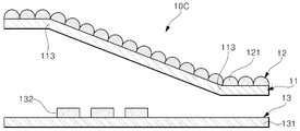
도 6을 참조하면, 본 실시예에 따른 조명 장치(10C)는, 광가이드부(11), 광가이드부(11) 상의 입체효과 형성부(12) 및 광가이드부(11)의 중간부에 빛을 조사하는 광원부(13)를 포함한다. 광가이드부(11)와 입체효과 형성부(12)의 조합은 광학 부재로 지칭될 수 있다. 광학 부재는 광원부(13)의 빛이 직접 조사되는 제1영역 외부에 배치되는 적어도 하나의 굴곡부(113)를 포함할 수 있다.Referring to FIG. 6, the
광가이드부(11), 입체효과 형성부(12) 및 광원부(13)는 광가이드부(11)의 제1영역이 광원(132)에 대하여 경사져 배치되고 제1영역의 양측에 두 굴곡부(113)를 구비하는 것을 제외하고 도 1 내지 도 5를 참조하여 앞서 설명한 조명 장치의 대응 구성요소와 실질적으로 동일할 수 있다.In the
굴곡부(113)는 광원(132)의 빛이 직접 조사되는 제1영역의 바깥쪽 즉, 광원(132)의 빛이 직접 조사되는 않는 제2영역에 마련된다. 제1영역(도 4의 A1 참조)은 광가이드부(11)에서 광원의 빛이 직접 조사되는 영역이다. 본 실시예에서 제1영역에 대응하는 광학 부재의 중간 부분은 인쇄회로기판(131)이나 광원(132)의 광출사면에 대하여 소정의 경사각을 갖는 경사면으로 배열된다. 굴곡부(113)는 제1영역의 양측 바깥쪽 즉 광학 부재 내에서 입사광이 이동하는 방향에서의 양측 가장자리 부분에 각각 마련되는 상부측 제1굴곡부와 하부측 제2굴곡부를 포함한다. 상부측 제1굴곡부(113)는 하부측 제2굴곡부에 비해 인쇄회로기판(131) 또는 광원(132)에서 더 멀리 위치하는 굴곡부이다.The
전술한 경우, 제1굴곡부, 제1영역 및 제2굴곡부(113)를 사이에 두고 배치하는 광학 부재의 양측면 가장자리 부분은 인쇄회로기판(131)이나 광원(132)의 광출사면에 대하여 평행하게 배열될 수 있다. 인쇄회로기판(131)은 연성 인쇄회로기판일 수 있다.In the above case, the edge portions of both sides of the optical member disposed with the first bent portion, the first region, and the second
본 실시예의 조명 장치(10C)에서 입체효과를 갖는 선형광을 이용하여 구현한 광이미지를 예시하면 도 7과 같다.7 illustrates an optical image implemented using linear light having a three-dimensional effect in the
도 7에 도시한 바와 같이, 본 실시예에 따른 조명 장치(10C)는, 광학 부재의 중간부 양측 가장자리 부분을 서로 다른 방향으로 구부려 굴곡부를 각각 마련한 후 광학 부재의 중간부가 광원에 대하여 경사지도록 배치함으로써, 광원의 빛이 경사진 중간부에 직접 조사될 때, 경사진 중간부인 제1영역에서 상부측의 제1굴곡부(113)를 향하여 복수의 선형광이 불꽃 모양으로 퍼져나가고 제1영역에서 하부측의 제2굴곡부를 향하여 복수의 선형광이 짧은 길이로 연장하는 광이미지를 구현할 수 있다.As shown in FIG. 7, in the
한편, 본 실시예의 조명 장치(10C)는, 하우징, 구동부 등을 추가로 구비할 수 있으며, 그 경우 조명 장치(10C)는 광학 부재 상에서의 두 굴곡부의 위치와 두 굴곡부 사이의 경사진 중간 부분에 광원의 빛이 직접 조사하는 것을 제외하고 도 2 및 도 3을 참조하여 앞서 설명한 조명 장치와 실질적으로 동일할 수 있다.On the other hand, the
도 8은 본 발명의 또 다른 실시예에 따른 조명 장치의 사시도이다. 도 9는 도 8의 조명 장치의 Ⅸ-Ⅸ선에 의한 부분 단면도이다. 도 10은 도 8의 조명 장치의 작동 원리를 설명하기 위한 단면도이다. 도 10은 도 9의 광학 부재를 뒤집어 배치한 경우에 대응한다.8 is a perspective view of a lighting device according to another embodiment of the present invention. 9 is a partial cross-sectional view of the lighting device of FIG. 8 taken along line IX-IX. 10 is a cross-sectional view for explaining an operating principle of the lighting device of FIG. 8. FIG. 10 corresponds to a case in which the optical member of FIG. 9 is placed upside down.
도 8 및 도 9를 참조하면, 본 실시예에 따른 조명 장치(10D)는, 평평한 판 또는 필름 형태의 광가이드부(11), 광가이드부(11) 일면에 y방향으로 순차 배열되는 복수의 단위패턴들을 구비하는 입체효과 형성부(12), 및 광가이드부(11)의 두께 방향에서 광가이드부(11)의 중간부에 빛을 조사하는 광원부를 포함한다.8 and 9, the
광원부(도 1의 13 참조)는 소정 폭의 단일 입사광(BL)을 x-y평면과 교차하는 방향에서 광가이드부(11)에 조사하는 LED 광원을 포함할 수 있다. 단일 입사광(BL)의 x방향에서의 폭은 어느 하나의 단위패턴의 패턴 연장 방향에서 광가이드부(12) 전체의 폭과 유사할 수 있다.The light source unit (see 13 of FIG. 1) may include an LED light source that irradiates the
광가이드부(11)는 입체효과 형성부(12)의 패턴 구조를 제외하고 도 1의 광가이드부와 실질적으로 동일할 수 있다.The
입체효과 형성부(12)는 광가이드부(11)의 서로 다른 영역에 각각 마련되는 4개 그룹의 복수의 단위패턴들(121a, 121b, 121c, 121d)을 포함한다. 입체효과 형성부(12)는 4개 그룹의 패턴들 사이사이에 이격부(17)를 구비한다.The three-dimensional
좀더 구체적으로 설명하면, 입체효과 형성부(12)의 각 그룹의 패턴(121a, 121b, 121c 또는 121d)은 제1면, 제2면 및 제3면을 구비한 복수의 프리즘 막대들이 병렬로 순차 배열되는 형상을 구비할 수 있다. 각 그룹의 단위패턴은 길이 방향이 x방향으로 연장하는 프리즘 막대 형태를 구비하고, 단위패턴의 제1면은 광가이드부(11)의 일면에 접하며, 단위패턴의 제2주면 및 제3주면은 인접한 다른 패턴의 제2면 및 제3면과 반복적으로 배열되어 요철 형태를 형성할 수 있다.More specifically, the
4개 그룹의 패턴들(121a, 121b, 121c 및 121d)은 단일 광가이드부(11)의 일면을 가공하여 일체형으로 형성될 수 있다. 각 패턴의 단위패턴들의 제1면이 광가이드부(11)의 일면 상에 평행하게 배열되는 면일 때, 제1면은 광가이드부(11)에 일체로 접하는 가상의 면이 된다.The four groups of
단위패턴의 제2면 및 제3면은 광가이드부(11)의 제1면 또는 제2면에 대하여 소정의 경사각을 갖는 경사면이 된다. 단위패턴의 제2면과 제3면은 각각 광가이드부(11)의 일면에 경사진 경사각을 갖는 면으로서 경사면에서의 굴절 및 반사에 의해 광가이드부(11)를 지나는 입사광을 제1경로로 한정하고 유도하여 선형광을 구현한다.The second and third surfaces of the unit pattern are inclined surfaces having a predetermined inclination angle with respect to the first surface or the second surface of the
즉, 광가이드부(11)의 내부를 이동하며 단위패턴들의 경사면에서 굴절 및 반사되는 입사광은 입사광이 직접 조사되는 제1영역(A1)에서 제2영역(A2)를 경유하여 제3영역(A3)으로 연장하면서 광가이드부(11)의 제1면 방향이나 제2면 방향으로 방출되고, 이때 복수의 단위패턴들의 배열 방향과 간접광원 효과에 의해 제1경로의 선형광으로 변환된다.That is, the incident light that moves inside the
입체효과 형성부(12)의 패턴에서 일정값 이상의 반사 또는 굴절 성능을 확보하기 위하여 단위패턴의 경사면은 반질반질한 또는 매끈한 경면으로 마련된다. 경면의 표면 거칠기(Rz)는 반사면에 대한 단면 곡선에서 가장 높은 봉우리 5개의 평균 높이와 가장 깊은 골짜기 5개의 평균 깊이의 차를 이용하는 10점 평균거칠기를 기준으로 측정 및 계산될 수 있다. 표면 거칠기는 기준길이 0.25㎜에서 약 0.8㎛ 이하, 바람직하게는 0.4㎛ 이하, 더욱 바람직하게는 0.1㎛ 이하로 설계될 수 있다. 표면 거칠기가 일정값(예컨대, 0.8㎛)을 초과하면 각 패턴에 대하여 원하는 반사 또는 굴절 성능이 일정 수준 이하로 감소하여 원하는 광이미지를 제대로 구현하기 어려울 수 있다.In order to secure reflection or refraction performance of a predetermined value or more in the pattern of the three-dimensional
이격부(17)는 제1경로의 선형광이 이동하는 방향과 평행한 방향으로 연장하며 인접한 두 그룹의 패턴들 사이에서 패턴이 형성되지 않은 영역으로 마련된다. 즉, 이격부(17)는 광가이드부(11)의 제1면에서 y방향으로 연장하며 소정 폭을 구비할 수 있다. 이러한 이격부(17)는 단일 광가이드부(11)의 일면을 가공하여 입체효과 형성부(12)의 복수 그룹의 패턴들을 형성하는 공정에서 입체효과 형성부(12)의 패턴들(121a, 121b, 121c, 121d)과 동시에 생성될 수 있다.The
이격부(17)를 이용하면, 광가이드부(11)의 두께 방향(z방향)과 직교하거나 교차하는 방향에서 광가이드부(11)의 제2면의 중간부에 x방향으로 단일 광폭을 갖는 빛이 조사될 때, 광가이드부(11)에 입사된 입사광을 복수 그룹의 패턴들에 의해 서로 분리되어 표현되는 4쌍의 선형광들으로 변환하여 표시할 수 있다. 4쌍의 선형광들은 광가이드부(11)의 y방향에서의 대략 중간 부분에서 중심 부분을 기준으로 +y방향과 -y방향으로 각각 진행하는 복수의 선형광들을 지칭한다.When the
입체효과를 갖는 선형광을 좀더 구체적으로 설명하면 다음과 같다.The linear light having a three-dimensional effect will be described in more detail as follows.
도 10을 참조하면, 광가이드부(11)의 중간부인 제1영역(A1)에 입사된 입사광은 광가이드부(11)의 내부에서 반사하며 일측에서 타측으로 이동한다. 이때, 광가이드부(11)의 일면 상의 입체효과 형성부(12)의 패턴(121)은 입사광을 굴절시키거나 반사시켜 진행 방향을 변경하고, 그에 의해 입사광이 광가이드부(11)의 제1면(111)이 향하는 제1면 방향이나 제1면의 반대측인 제2면이 향하는 제2면 방향으로 방출되도록 작용한다.Referring to FIG. 10, incident light incident on a first region A1 that is an intermediate portion of the
여기서, 순차 배열되는 복수의 단위패턴들은 입사광의 반사 및 굴절을 통해 제1영역(A1)에서 제3영역(A3)으로 가면서 광경로가 점점 더 길어지는 간접광원들로서 작용한다. 따라서, 광가이드부(11)의 중간부에서 제1측면 가장자리로 진행하는 제1입사광과 중간부에서 제1측면 가장자리의 반대측인 제2측면 가장자리로 진행하는 제2입사광은, 단위패턴들의 각 경사면에서의 반사 및 굴절에 의해 제1영역(A1)에서 제3영역(A3)으로 가면서 광경로의 길이가 길어지면서 순차 배열된 점광원 형태의 간접광원들에 의해 광가이드부(11) 외부로 방출되는 선형광으로 각각 변환된다. 선형광은 광경로가 길어짐에 따라 외부의 기준점 혹은 관측점을 기준으로 더 멀리 위치하는 간접광원이 되고, 그에 의해 진행 방향으로 깊이감을 갖는 입체효과 선형광으로 표현된다.Here, the plurality of sequentially arranged unit patterns act as indirect light sources whose optical path becomes longer and longer while going from the first region A1 to the third region A3 through reflection and refraction of incident light. Accordingly, the first incident light proceeding from the middle portion of the
다시 말해서, 광가이드부(11)의 제1영역(A1)에 위치하는 제1단위패턴에 의한 제1간접광원(LS1)이 제1단위패턴으로부터 제1거리(L1)에 위치하는 것으로 관측될 때, 제2영역(A2)에 위치하는 제2단위패턴에 의한 제2간접광원(LS2)은 제1거리(L1)보다 먼 제2거리(L2)에 위치하는 것으로 관측되고, 제3영역(A3)에 위치하는 제3단위패턴에 의한 제3간접광원(LS3)은 제2거리(L2)보다 먼 제3거리(L3)에 위치하는 것으로 관측된다. 그리고, 동일 광원으로부터의 광경로 차이에 따라 제2간접광원(LS2)의 빛의 세기(광도)는 제1간접광원(LS1)의 광도보다 작고, 제3간접광원(LS3)의 광도보다 크다.In other words, it can be observed that the first indirect light source LS1 by the first unit pattern located in the first area A1 of the
전술한 구성에 의하면, 외부의 기준점에서 조명 장치(10D)는 광가이드부(11)의 패턴배열면(제1면)이나 제2면(112)과 직교하는 방향에서의 거리 벡터 성분이 증가하고 휘도가 감소하는 입체효과 선형광을 이용하여 광이미지를 구현할 수 있다.According to the above-described configuration, at the external reference point, the
또한, 본 실시예에 의하면, 광가이드부(11)와 입체효과 형성부(12)로 형성되는 광학 부재에 굴곡부를 배치하는 경우, 조명 장치(10D)는 도 2, 도 4 또는 도 6을 참조하여 앞서 설명한 조명 장치와 유사하게 다양한 형상의 광이미지를 구현할 수 있다.In addition, according to the present embodiment, in the case of arranging the bent portion in the optical member formed of the
도 11은 본 발명의 또 다른 실시예에 따른 조명 장치의 사시도이다.11 is a perspective view of a lighting device according to another embodiment of the present invention.
도 11을 참조하면, 본 실시예에 따른 조명 장치(10E)는, 광가이드부(11), 입체효과 형성부(12) 및 광원부를 포함하여 구성된다. 입체효과 형성부(12)는 광가이드부(11)의 서로 다른 영역에 y방향으로 순차 배열되는 복수 그룹의 패턴들과, 서로 인접한 패턴 그룹들 사이에서 광가이드부(11)의 y방향으로 연장하는 격벽(18)을 구비한다.Referring to FIG. 11, the
본 실시예의 조명 장치(10E)는, 광가이드부(11)의 두께 방향(z방향)이나 두께 방향에 대하여 경사진 방향에서 광가이드부(11)의 y방향에서의 중간부에 빛이 조사될 때, 광가이드부(11) 내부의 입사광을 4개 그룹의 패턴들에 의해 굴절 및 반사하여 입체효과 형성부(12)의 각 그룹의 패턴 배열 방향을 따라 연장하는 4쌍의 선형광들로 변환할 수 있다.In the
입체효과 형성부(12)는 광가이드부(11)의 일면 일부분을 제거한 형태로 마련될 수 있으나, 이에 한정되지 않고, 광가이드부(11)의 일면에 복수의 패턴들을 구비한 별도의 패턴층을 접합하여 마련될 수 있다. 그 경우, 패턴층의 굴절률은 광가이드부(11)의 굴절률과 동일하거나 소정의 굴절률 차이(약 0.2 이하)를 갖도록 설계될 수 있다.The three-dimensional
입체효과 형성부(12)의 각 패턴 그룹은 반원통 막대 형태의 단위패턴들(121a, 121b, 121c, 121d)을 포함하여 구성된다. 각 패턴 그룹의 단위패턴은 반원주면 및 이 반원주면과 마주하는 평면을 구비한 반원통 막대 형태를 구비하며, 여기서 반원통 막대의 평면 부분은 광가이드부의 일면에 접하도록 배열되고 그 반원주면 부분은 y방향에서 나란하게 순차 배열될 수 있다.Each pattern group of the three-dimensional
격벽(18)은 입체효과 형성부(12)의 패턴들이 마련되지 않은 부분으로서 이 부분은 광가이드부(11)의 일부분으로 마련되거나 별도의 부재를 패턴 그룹들 사이에 배치하여 마련될 수 있다. 격벽(18)은 광가이드부(11) 또는 입체효과 형성부(12)와 다른 굴절률, 색상 등을 가진 재료로 마련될 수 있다. 이러한 격벽(18)을 이용하면, 단일 입사광을 복수의 선형광으로 분리하여 표현할 수 있다.The
본 실시예에 의하면, 광가이드부의 두께 방향 또는 두께 방향과 경사진 방향에서 광가이드부의 일방향의 중간부에 빛이 조사될 때, 광가이드부 내부의 입사광을 단위패턴들의 각 경사면에서의 순차적인 반사와 굴절에 의해 광가이드부의 제1면 방향이나 제2면 방향으로 유도하면서 단위패턴들의 각 패턴 배열 방향과 직교하는 제1경로의 복수의 선형광을 구현한다. 복수의 선형광은 광가이드부의 중간부에서 중간부 양측으로 진행하는 적어도 한 쌍의 선형광들을 포함한다.According to this embodiment, when light is irradiated in the middle of one direction of the light guide part in the thickness direction of the light guide part or in the thickness direction and inclined direction, the incident light inside the light guide part is sequentially reflected from each inclined surface of the unit patterns. A plurality of linear lights of a first path orthogonal to each pattern arrangement direction of the unit patterns are implemented while being guided in the direction of the first surface or the second surface of the optical guide unit by refraction of and refraction. The plurality of linear lights include at least a pair of linear lights traveling from the middle portion of the optical guide portion to both sides of the middle portion.
또한, 본 실시예에 의하면, 광가이드부(11)와 입체효과 형성부(12)로 형성되는 광학 부재에 굴곡부를 배치하는 경우, 조명 장치(10E)는 도 2, 도 4 또는 도 6을 참조하여 앞서 설명한 조명 장치와 유사하게 다양한 형상의 광이미지를 구현할 수 있다.In addition, according to the present embodiment, in the case of arranging the bent portion in the optical member formed of the
도 12는 본 발명의 또 다른 일 실시예에 따른 조명 장치의 사시도이다.12 is a perspective view of a lighting device according to another embodiment of the present invention.
도 12를 참조하면, 본 실시예에 따른 조명 장치(10F)는, 광가이드부(11), 입체효과 형성부(12) 및 광원부를 포함하여 구성된다.Referring to FIG. 12, the
입체효과 형성부(12)는 광가이드부(11)의 x방향으로 각각 연장하며 y방향으로 순차 배열되는 패턴을 구비한다. 즉, 본 실시예에 따른 조명 장치(10F)에 있어서, 입체효과 형성부(12)는 이격부나 격벽에 의해 복수 그룹의 패턴들로 분리되지 않고 패턴 연장 방향 중간에 패턴 배열 방향으로 연장하는 이격부나 격벽이 없는 단일 그룹의 복수의 단위패턴들(121)을 포함한다.The three-dimensional
전술한 입체효과 형성부(12)의 패턴 구조를 제외하고 본 실시예의 조명 장치(10F)는 도 8 또는 도 11을 참조하여 앞서 설명한 조명 장치와 실질적으로 동일할 수 있으므로, 동일하거나 유사한 구성요소에 대한 상세 설명은 생략한다.Except for the pattern structure of the three-dimensional
본 실시예에 있어서, 입체효과 형성부(12)의 단위패턴(121)은 제1면(1211), 제2면(1212), 제3면(1213) 및 제4면(1214)을 갖는 사각 막대 형상 또는 사다리꼴의 단면 형상을 구비한다. 광가이드부(11)의 일면에서 복수의 단위패턴들(121)은 그 길이 방향이 x방향(패턴 연장 방향)으로 놓이고, y방향에서 반복적으로 순차 배열된다.In this embodiment, the
단위패턴(121)에 있어서, 제1면(1211)은 광가이드부(11)의 제1면이나 제2면에 평행하게 배열될 수 있다. 제2면(1213)은 제1면(1211)과 평행하거나 평행하지 않을 수 있다. 제3면(1212) 및 제4면(1214)은 제1면(1211)과 소정의 경사각을 갖고 경사진 경사면일 수 있다.In the
제3면(1213)이 광가이드부(11)의 제2면 또는 패턴배열면과 평행하게 배치되는 경우, 입체효과 형성부(12) 내에서 제3면(1213)은 간접광원으로서 기능하지 못하고 선형광을 단절시키는 부분(이하, 단절부)이 될 수 있다. 이러한 단절부는 점선 형태의 선형광 형상으로 광이미지를 구현하는 경우에 적절하게 이용될 수 있다. 연속적인 선형광을 구현하고자 하는 경우, 단절부는 약 10㎛ 이하로 설정된다.When the
제3면(1213)이 광가이드부(11)의 패턴배열면과 평행하지 않고 광가이드부(11)의 패턴배열면과 소정의 경사각을 갖도록 배치되는 경우, 제3면(1213)은 제2면(1212) 또는 제4면(1214)과 함께 입사광을 굴절 및 반사시켜 광가이드부(11)의 제1면 방향이나 제2면 방향으로 입사광을 유도하는 경사면이 될 수 있다.When the
본 실시예의 조명 장치(10F)는 x방향으로 나열되어 y방향의 중간부에 복수의 빛을 조사하는 복수의 LED 소자들을 가진 광원을 포함할 수 있다. 그 경우, 조명 장치(10F)는 입체효과 형성부(12)의 단일 패턴을 이용하여 도 8 또는 도 11의 조명 장치의 경우와 유사하게 y방향의 중간부에서 양측면으로 진행하는 복수 쌍의 입체효과 선형광을 포함한 광이미지를 구현할 수 있다.The
한편, 본 실시예의 복수의 단위패턴들(121)을 포함하는 조명 장치(10F)는, 복수의 단위패턴들(121)의 각 패턴 연장 방향이 x방향으로 서로 평행하게 연장하는 구조를 갖지만, 이에 한정되지는 않는다. 예를 들어, 조명 장치(10F)는 변형 실시예에서 단위패턴의 x방향의 일단에서 타단으로 가면서 적어도 하나의 단위패턴의 단면 폭이 점진적으로 커져 x방향의 일단의 소정 점을 중심으로 광경로가 꺾이거나 완만하게 휘어지도록 설계되는 복수의 단위패턴들을 포함할 수 있다.On the other hand, the
본 실시예에 의하면, 광가이드부의 두께 방향 또는 두께 방향과 경사진 방향에서 광가이드부의 일방향 중간부에 빛이 조사될 때, 광가이드부 내부의 입사광을 단위패턴들의 각 경사면에서의 순차적인 반사와 굴절에 의해 광가이드부의 제1면 방향이나 제2면 방향으로 유도하면서 단위패턴들의 각 패턴 연장 방향과 직교하는 방향으로 연장하는 서로 평행한 제1경로들의 복수의 선형광을 구현할 수 있다.According to the present embodiment, when light is irradiated to an intermediate portion in one direction of the optical guide portion in the thickness direction of the optical guide portion or in the thickness direction and inclined direction, the incident light inside the optical guide portion is sequentially reflected from each inclined surface of the unit patterns. A plurality of linear lights of parallel first paths extending in a direction orthogonal to each pattern extension direction of the unit patterns while being guided in the direction of the first surface or the second surface of the light guide unit by refraction may be realized.
또한, 본 실시예에 의하면, 광가이드부(11)와 입체효과 형성부(12)로 마련되는 광학 부재에 굴곡부를 배치하는 경우, 조명 장치(10F)는 도 도 2, 도 4 또는 도 6에 도시한 조명 장치와 유사하게 복수 쌍의 선형광들에 의한 다양한 형상의 광이미지를 구현할 수 있다.In addition, according to the present embodiment, in the case of arranging the bent portion on the optical member provided with the
도 13은 본 발명의 또 다른 실시예에 따른 조명 장치의 평면도이다.13 is a plan view of a lighting device according to another exemplary embodiment of the present invention.
도 13을 참조하면, 본 실시예에 따른 조명 장치(10G)는, 광가이드부(11), 제1 내지 제3 입체효과 형성부(12a, 12b, 12c), 제1 내지 제3 광원부(20a, 20b, 20c) 및 아우터 렌즈(30)를 포함하여 구성된다.Referring to FIG. 13, the
광가이드부(11)는 평면 또는 정면에서 볼 때 소정의 차량 램프 모양으로 마련된다. 여기서, 차량 램프는 헤드라이트, 후방라이트, 실내 조명, 도어 스카프, 안개등 중 어느 하나일 수 있으나, 이에 한정되는 것은 아니다. 광가이드부(11)는 그 모양이나 형태를 제외하고 도 1, 도 8, 도 11 또는 도 12의 광가이드부와 동일할 수 있다.The
제1 입체효과 형성부(12a)는 광가이드부(11)의 제1영역에 마련된다. 제1 입체효과 형성부(12a)의 복수의 단위패턴들(121a)은 제1영역에서 제1A방향으로 각각 연장하며 제1A방향과 교차하거나 직교하는 제1B방향으로 순차 배열된다. 단위패턴(121a)은 제1B방향에서 광가이드부(11)의 패턴패열면에 대하여 제1경사각을 갖는 경사면을 구비한다.The first three-dimensional
제2 입체효과 형성부(12b)는 광가이드부(11)의 제2영역에 마련된다. 제2영역은 제1영역과 중첩되지 않는다. 제2 입체효과 형성부(12b)의 복수의 단위패턴들(121b)은 제2영역에서 제2A방향으로 각각 연장하며 제2A방향과 교차하거나 직교하는 제2B방향으로 순차 배열된다. 제2A방향은 제1A방향과 평행하지 않을 수 있고, 제2B방향은 제1B방향과 평행하지 않을 수 있다. 단위패턴(121b)은 제2B방향에서 광가이드부(11)의 패턴패열면에 대하여 제2경사각을 갖는 경사면을 구비한다. 제2경사각은 제1경사각과 동일하거나 다를 수 있다.The second three-dimensional
제3 입체효과 형성부(12c)는 광가이드부(11)의 제3영역에 마련된다. 제3영역은 제1영역 및 제2영역과 중첩되지 않는다. 제3 입체효과 형성부(12c)의 복수의 단위패턴들(121c)은 제3영역에서 제3A방향으로 각각 연장하며 제3A방향과 교차하거나 직교하는 제3B방향으로 순차 배열된다. 제3A방향은 제1A방향 또는 제2A방향과 평행하지 않을 수 있고, 제3B방향은 제1B방향 또는 제2B방향과 평행하지 않을 수 있다. 단위패턴(121c)은 제3B방향에서 광가이드부(11)의 패턴패열면에 대하여 제3경사각을 갖는 경사면을 구비한다. 제3경사각은 제1경사각 및 제2경사각 중 적어도 어느 하나와 동일하거나 둘 모두와 다를 수 있다.The third three-dimensional
제1광원부(132a)는 제1영역의 중간부에 빛을 조사하도록 배치된다. 광가이드부(11)의 제1영역은 제1광원부(132a)에 대하여 경사지거나 절곡될 수 있다(도 7 및 도 9 참조). 제2광원부(132b)는 제2영역의 중간부에 빛을 조사하도록 배치된다. 광가이드부(11)의 제2영역은 제2광원부(132b)에 대하여 경사지거나 절곡될 수 있다. 그리고, 제3광원부(132c)는 제3영역의 중간부에 빛을 조사하도록 배치된다. 광가이드부(11)의 제3영역은 제3광원부(132b)에 대하여 경사지거나 절곡될 수 있다.The first light source portion 132a is disposed to irradiate light in the middle portion of the first area. The first area of the
전술한 제1 내지 제3 광원부(132a, 132b, 132c)는 아우터 렌즈(30)가 결합되는 조명 장치(10G)의 하우징에 의해 아우터 렌즈(30)의 일면 상에 지지되는 광원을 구비할 수 있다. 여기서, 제1 내지 제3 광원부(132a, 132b, 132c) 중 적어도 어느 하나의 광원은 광가이드부(11) 및 입체효과 형성부와 함께 적어도 하나의 입체효과 광학 모듈로 마련될 수 있다. 그리고, 제1 내지 제3 입체효과 형성부(12a, 12b, 12c) 중 적어도 어느 하나와 광가이드부(11)의 적어도 일부분으로 이루어지는 적어도 하나의 광학 부재는 아우터 렌즈(30)의 일면에 접합되거나 아우터 렌즈(30)의 일면 상에 배치될 수 있다. 조명 장치가 차량 램프로 구현되는 경우, 각 광원부는 차량 배터리(19)에 연결되어 차량 배터리의 전원에 의해 동작할 수 있다.The first to third light source units 132a, 132b, and 132c described above may include light sources supported on one surface of the
제1 내지 제3 광원부(132a, 132b, 132c)가 연성 인쇄회로기판을 구비하고 레진층으로 광가이드부(11)를 형성하면, 조명 장치(10G)는 곡면을 갖는 아우터 렌즈(20)의 일면에 접합되거나 아우터 렌즈(20)의 곡면에 따라 적어도 1 이상의 변곡점을 갖고 휘어져 배치될 수 있다.When the first to third light source units 132a, 132b, and 132c have a flexible printed circuit board and form the
전술한 구성에 의하면, 각 광원부(132a, 132b, 132c)의 빛이 광가이드부(11)의 두께 방향이나 두께 방향과 경사진 방향에서 광가이드부의 각 영역의 중간부에조사될 때, 각 입체효과 형성부의 단위패턴들(121a, 121b, 121c)은 배열 방향의 양 방향으로 입사광을 가이드하고 한정하여 선형광(GL)을 표현한다. 물론, 제1 내지 제3 입체효과 형성부는 광원과의 상대적인 배치 설계에 따라 패턴 배열 방향의 양방향이 아닌 일방향으로 연장하는 선형광을 구현할 수 있다.According to the above-described configuration, when light from each light source unit 132a, 132b, 132c is irradiated to the middle of each area of the light guide unit in the thickness direction or the thickness direction and inclined direction of the
또한, 본 실시예에 의하면, 조명 장치(10G)에 있어서, 광가이드부(11)와 제1 입체효과 형성부(12a)로 마련되는 제1 광학부재부, 광가이드부(11)와 제2 입체효과 형성부(12b)로 마련되는 제2 광학부재부, 및 광가이드부(11)와 제3 입체효과 형성부(12c)로 마련되는 제3 광학부재부 중 적어도 어느 하나는 곡률을 갖거나 곡면을 갖도록 휘어질 수 있다. 그러한 경우, 조명 장치(10G)는 도 2, 도 4 또는 도 6의 조명 장치와 유사하게 굴곡부를 이용한 다양한 선형광의 광이미지를 구현할 수 있다. 아울러, 본 실시예의 조명 장치(10G)는 차량 램프 외에 실내외의 일반 조명 장치, 전시회 등에 사용되는 디자인 조명 장치, 유연한 응용 제품 등에 손쉽게 이용될 수 있다.In addition, according to the present embodiment, in the
도 14 내지 도 16은 본 발명에 따른 조명 장치에 채용가능한 패턴 구조에 대한 예시도이다.14 to 16 are exemplary views of a pattern structure employable in the lighting device according to the present invention.
도 14를 참조하면, 본 실시예에 따른 조명 장치의 입체효과 형성부(12)는 패턴을 구비하고, 패턴은 복수의 단위패턴들(121)을 구비한다. 단위패턴(121)은 삼각형 단면 형상을 구비한다.Referring to FIG. 14, the three-dimensional
단위패턴(121)이 삼각형 단면 형상을 구비하면, 단위패턴(121)의 경사면(123)은 제1면 또는 패턴배열면(도 1의 111 참조)에 대하여 소정의 경사각을 갖는다. 다시 말해서, 경사면(123)은 패턴배열면과 직교하는 z방향에 대하여 경사진 경사각(θ)을 구비할 수 있다.When the
경사각(θ)은 약 5°보다 크고 약 85°보다 작다. 경사각(θ)은 광가이드부의 굴절률을 고려하여 좀더 한정될 수 있으나, 기본적으로 경사면(123)에서의 일정 수준 이상의 반사 및 굴절을 고려할 때 약 5° 내지 약 85°범위에서 적절하게 설계될 수 있다.The inclination angle θ is greater than about 5° and less than about 85°. The inclination angle θ may be more limited in consideration of the refractive index of the optical guide, but may be appropriately designed in the range of about 5° to about 85° when considering reflection and refraction of a certain level or more on the
광가이드부의 굴절률이 약 1.30 내지 약 1.80일 때, 단위패턴(121)의 일측 경사면(123)의 경사각은 기준 방향(z방향 또는 y방향)에 따라 33.7°보다 크고 50.3°보다 작은 범위를 갖거나 49.7°보다 크고 56.3°보다 작은 범위를 가질 수 있다.When the refractive index of the optical guide part is about 1.30 to about 1.80, the inclination angle of one side of the
또한, 광가이드부 및 복수의 단위패턴들로 형성되는 광학 부재는 고굴절률 소재를 이용하여 마련될 수 있다. 예컨대, 고광도 LED 제조의 경우, 특정 입사각의 빛이 반도체 다이를 지나 캡슐 소재를 투과할 때 반도체 다이(n=2.50~3.50)와 통상의 고분자 캡슐소자(n=1.40~1.60)와의 사이의 n값(굴절률) 차이에 의해 내부 전반사되고 그에 의해 소자의 광추출 효율이 저하하게 되는데, 이를 적절히 해소하기 위하여 고굴절률의 고분자(n=1.80~2.50)를 이용한다. 본 실시예에서는 고광도 LED 제조에 이용되는 고굴절률 고분자(n=1.80~2.50)를 활용하여 광학 부재를 마련할 수 있다. 그 경우, 본 실시예에 따른 단위패턴(121)의 경사면(123)의 경사각은 광학 부재의 굴절률에 따라 23.6°보다 크고 약 56.3°보다 작은 범위를 갖거나 혹은 33.7°보다 크고 66.4°보다 작은 범위를 가질 수 있다.In addition, the optical member formed of the optical guide portion and a plurality of unit patterns may be prepared using a high refractive index material. For example, in the case of high-intensity LED manufacturing, when light of a specific incidence angle passes through the semiconductor die and passes through the capsule material, the n-value between the semiconductor die (n = 2.50 to 3.50) and a typical polymer capsule device (n = 1.40 to 1.60). The (refractive index) difference causes total internal reflection and thereby lowers the light extraction efficiency of the device. In order to properly solve this, a high refractive index polymer (n=1.80~2.50) is used. In this embodiment, an optical member may be prepared by utilizing a high refractive index polymer (n=1.80 to 2.50) used for manufacturing a high-intensity LED. In that case, the inclination angle of the
또한, 구현에 따라서, 굴절률 조절을 위해 복수의 패턴들 상에는 적어도 하나의 고굴절률의 기능층이 코팅될 수 있다.In addition, depending on implementation, at least one functional layer having a high refractive index may be coated on the plurality of patterns to adjust the refractive index.
전술한 굴절률에 따른 경사각은 스넬의 법칙에 따른 것으로 이를 수식으로 나타내면 다음의 수학식 1과 같다.The inclination angle according to the above-described refractive index is according to Snell's law, and this is expressed as an equation as in

수학식 1에서 sinθ1은 제1굴절률(n1)의 제1매질에서의 빛의 진행각 또는 입사각이고, sinθ2는 제2굴절률(n2)의 제2매질에서의 빛의 입사각 또는 진행각이다,In
전술한 바와 같이, 본 실시예의 단위패턴의 경사면은 입사광을 적절하게 반사시키거나 굴절시킬 수 있는 경사각으로서 작게는 약 5°정도, 크게는 약 85°의 경사각(θ)을 갖도록 마련될 수 있다. 일실시예에서, 단위패턴(121)은 전술한 경사면에 더하여 제조 공정의 편의 등을 위해 밑면의 폭(w) 대 높이(h)를 소정 비율로 한정할 수 있다. 밑면의 폭은 단위패턴들의 주기 혹은 피치에 대응할 수 있다.As described above, the inclined surface of the unit pattern according to the present embodiment is an inclination angle capable of appropriately reflecting or refracting incident light, and may be provided to have an inclination angle (θ) of about 5° as small as about 85°. In one embodiment, the
예를 들어, 선형광의 입체효과가 강조되도록 입체효과 형성부의 패턴들에 대하여 패턴 설계하는 경우, 단위패턴(121)의 폭(w)은 단위패턴의 높이(h)와 같거나 작도록 마련될 수 있다. 또한, 선형광이 상대적으로 긴 이미지를 표현하도록 입체효과 형성부의 패턴을 설계하는 경우, 단위패턴의 폭(w)은 단위패턴의 높이(h)보다 크도록 마련될 수 있다. 또한, 단위패턴(121)이 렌티귤러(lenticular) 모양을 가지는 경우, 단위패턴(121)의 폭 대 높이의 비율(h/w)은 약 1/2 이하이거나 그 경사면의 경사각(θ)이 약 45°이하가 되도록 마련될 수 있다.For example, when a pattern is designed for the patterns of the three-dimensional effect forming unit so that the three-dimensional effect of linear light is emphasized, the width w of the
이와 같이, 본 실시예에서는 단위패턴(22)의 폭(w)과 높이(h)를 특성조절용 인자로 이용하여 원하는 디자인의 선형광이나 입체효과광의 광이미지를 효과적으로 제어할 수 있다.As described above, in this embodiment, the optical image of the linear light or the three-dimensional effect light of a desired design can be effectively controlled by using the width (w) and the height (h) of the unit pattern 22 as a characteristic adjustment factor.
본 실시예에 있어서, 입체효과 형성부(12) 내의 서로 인접한 두 단위패턴들 사이의 폭(w)(피치에 대응할 수 있음)은 10㎛ 내지 500㎛일 수 있다. 이러한 폭(w)은 제1경로 상에서 복수의 패턴들 사이의 평균 간격일 수 있으며, 패턴 설계나 원하는 광이미지 형상에 따라 조정될 수 있다.In this embodiment, a width w (which may correspond to a pitch) between two unit patterns adjacent to each other in the three-dimensional
도 15를 참조하면, 본 실시예에 따른 조명 장치의 입체효과 형성부(12)의 패턴 설계 시, 복수의 단위패턴들(121)은 반원형 또는 반타원형 단면 형상을 갖도록 마련될 수 있다. 단위패턴(121)은 광가이드부의 두께 방향(z방향)이나 y방향에서 소정 각도로 기울어진 경사면을 구비한다. 단위패턴(121)은 z방향에서의 중심선(미도시)을 기준으로 대칭 형태를 구비할 수 있으나, 이에 한정되지는 않는다.Referring to FIG. 15, when designing a pattern of the three-dimensional
본 실시예에서 단위패턴(121)의 경사면은 단위패턴의 반원형 단면 구조에서 외접하는 직선상의 가상의 경사면을 고려할 수 있고, 이러한 경사면은 반원형 외표면을 따라서 가변하는 0°보다 크고 90°보다 작은 경사각(θ)을 가질 수 있다. 즉, 단위패턴(121)의 경사면은 대략 반원호 상의 임의의 점에 접하는 경사면을 가지므로, 모든 예각의 경사각(θ)을 가질 수 있다.In this embodiment, the inclined surface of the
또한, 본 실시예의 입체효과 형성부(12)는 서로 인접한 두 단위패턴들 사이에 마련되는 이격부(102)를 포함하여 구성될 수 있다. 즉, 복수의 단위패턴들(121)이 제1단위패턴(Cm-1), 제2단위패턴(Cm) 및 제3단위패턴(Cm+1)(여기서, m은 2 이상의 자연수임)을 포함할 때, 입체효과 형성부(12)는 제1단위패턴(Cm-1)과 제2단위패턴(Cm) 사이 및 제2단위패턴(Cm)과 제3단위패턴(Cm+1) 사이에 마련되는 이격부(102)를 포함할 수 있다.In addition, the three-dimensional
이격부(102)는 광가이드부의 제1면(111)에서 단위패턴이 형성되지 않은 부분으로서 인접한 두 단위패턴들 사이에 위치하는 제1면(111)의 일부분일 수 있다. 또한, 이격부(102)는 서로 인접한 두 단위패턴들 사이의 유격으로서 제조공정의 편의를 위해 마련된 것일 수 있다. 이격부(102)는 제조공정이나 특정 구현의 패턴 설계에 따라 생략가능하다.The
이격부(102)의 제2폭(w1)은 단위패턴(121)의 제1폭(w)보다 작다. 이격부(102)의 제1폭(w1)은 단위패턴(121)의 제1폭(w)의 약 1/5 이하이거나 수㎛ 이하일 수 있다. 이때, 단위패턴들의 주기 또는 피치는 제1폭(w)과 제2폭(w1)을 더한 값에 대응할 수 있다.The second width w1 of the
도 16을 참조하면, 본 실시예에 따른 조명 장치의 입체효과 형성부(12)의 패턴 설계 시, 단위패턴(121)은 다각형 단면 형상을 구비할 수 있다. 단위패턴(121)의 경사면(123)은 꺽은 선 그래프 형상을 가질 수 있다.Referring to FIG. 16, when designing a pattern of the three-dimensional
본 실시예에서 단위패턴(121)의 경사면(123)은 광가이드부의 제1면(111)과 직교하는 방향(z방향)에서 꺽은 선 그래프의 선분 개수에 따라 복수의 경사각(θ1, θ2)을 갖도록 마련될 수 있다. 제2경사각(θ2)은 제1경사각(θ1)보다 클 수 있다. 제1 및 제2 경사각(θ1, θ2)은 약 5°보다 크고 약 85°보다 작은 범위에서 설계될 수 있다.In this embodiment, the
또한, 본 실시예의 입체효과 형성부(12)는 서로 인접한 두 단위패턴들 사이의 이격부(102)를 더 구비할 수 있다. 이격부(102)의 폭(w1)은 입체효과 형성부(12)상에서의 자연스러운 선형광의 구현을 위해 단위패턴의 폭(w)보다 작다. 이격부(102)의 폭(w1)은 수㎛ 이하로 설계된다. 이격부(102)의 폭(w1)은 가능한 한 작게 설계되거나 그 자체가 생략되도록 설계될 수 있다.In addition, the three-dimensional
또한, 본 실시예의 입체효과 형성부(12)는 단위패턴(121) 상에 제1면(111)과 평행한 단절면(125)을 구비할 수 있다. 단절면(125)은 실질적으로 입사광의 반사나 굴절을 통해 입사광을 외부로 방출되도록 작용하지 못하는 부분으로서, 복수의 단위패턴들에 의해 구현되는 선형광이 단절면(125)에 대응하는 부분에서 단절되어 표현될 수 있으므로, 단절면(125)의 폭(w2)은 원하는 형상의 선형광 구현을 위해 수㎛ 이하에서 적절하게 설계될 수 있다.In addition, the three-dimensional
이상으로 본 발명의 기술적 사상을 예시하기 위한 바람직한 실시예와 관련하여 설명하고 도시하였지만, 본 발명은 이와 같이 도시되고 설명된 그대로의 구성 및 작용에만 국한되는 것은 아니며, 기술적 사상의 범주를 일탈함 없이 본 발명에 대해 다수의 적절한 변형 및 수정이 가능함을 본 발명이 속하는 기술분야에서 통상의 지식을 가진 자들은 잘 이해할 수 있을 것이다. 따라서 그러한 모든 적절한 변형 및 수정과 균등물들도 본 발명의 범위에 속하는 것으로 간주되어야 할 것이다.As described above and shown in connection with a preferred embodiment for illustrating the technical idea of the present invention, the present invention is not limited to the configuration and operation as shown and described as described above, without departing from the scope of the technical idea It will be well understood by those of ordinary skill in the art that a number of suitable modifications and variations are possible for the present invention. Accordingly, all such suitable modifications, modifications and equivalents should be considered to be within the scope of the present invention.
10, 10A, 10B, 10C, 10D, 10E, 10F, 10G: 조명 장치
11: 광가이드부
12, 12a, 12b, 12c: 입체효과 형성부
121, 121a, 121b, 121c: 단위패턴
13, 13a, 13b, 13c: 광원부
14: 하우징
15: 구동부
16: 굴곡지지부
17: 이격부
18: 격벽
19: 차량 배터리
20a, 20b, 20c: 광원
30: 아우터 렌즈
113: 굴곡부10, 10A, 10B, 10C, 10D, 10E, 10F, 10G: lighting devices
11: Optical guide part
12, 12a, 12b, 12c: three-dimensional effect forming part
121, 121a, 121b, 121c: unit pattern
13, 13a, 13b, 13c: light source unit
14: housing
15: drive unit
16: flexure support
17: separation
18: bulkhead
19: vehicle battery
20a, 20b, 20c: light source
30: outer lens
113: bend
Claims (23)
상기 기판 상에 배치되는 광원;
상기 광원과 마주보는 제1면 및 상기 제1면의 반대측인 제2면을 구비하고 상기 기판 상에 이격 배치되는 광가이드부; 및
상기 광가이드부의 상기 제2면에 배치되는 입체효과 형성부를 포함하고,
상기 입체효과 형성부는 복수의 단위패턴들을 포함하고,
상기 광원은 상기 제1면 방향으로 빛을 출사하고,
상기 광가이드부는 상기 기판과의 이격 거리가 일정한 제1 영역 및 상기 기판을 기준으로 기울어진 제2 영역을 포함하고,
상기 광가이드부의 제2 영역은 상기 제1 영역에서 멀어질수록 상기 기판과의 이격 거리가 변화하는 조명 장치.Board;
A light source disposed on the substrate;
An optical guide portion having a first surface facing the light source and a second surface opposite to the first surface, and spaced apart on the substrate; And
And a three-dimensional effect forming part disposed on the second surface of the optical guide part,
The three-dimensional effect forming unit includes a plurality of unit patterns,
The light source emits light in the direction of the first surface,
The optical guide unit includes a first region having a constant separation distance from the substrate and a second region inclined with respect to the substrate,
The lighting device of the second area of the light guide part is a distance from the substrate to change as the distance from the first area.
상기 복수의 단위패턴들은 상기 광원의 빛이 상기 광가이드부 외부에서 내부로 입사되는 제1영역과 가장 가까운 거리인 제1거리, 상기 제1거리보다 먼 제2거리 및 상기 제2거리보다 먼 제3거리를 갖고 순차 배열되는 제1단위패턴, 제2단위패턴 및 제3단위패턴을 포함하고,
여기서, 상기 제2단위패턴의 경사면에 의한 제2더미광원에서 상기 제2단위패턴의 경사면까지의 제2거리는, 상기 제1단위패턴의 경사면에 의한 제1더미광원에서 상기 제1단위패턴의 경사면까지의 제1거리보다 길고, 상기 제3단위패턴의 경사면에 의한 제3더미광원에서 상기 제3단위패턴의 경사면까지의 제3거리보다 짧은 조명 장치.The method according to claim 1,
The plurality of unit patterns include a first distance that is the closest distance to a first area where light from the light source is incident inside the light guide unit, a second distance farther than the first distance, and a second distance farther than the second distance Including a first unit pattern, a second unit pattern, and a third unit pattern that are sequentially arranged with three distances,
Here, the second distance from the second dummy light source by the inclined surface of the second unit pattern to the inclined surface of the second unit pattern is the inclined surface of the first unit pattern from the first dummy light source by the inclined surface of the first unit pattern A lighting device that is longer than the first distance to and shorter than the third distance from the third dummy light source by the inclined surface of the third unit pattern to the inclined surface of the third unit pattern.
상기 복수의 단위패턴들은 입사광을 상기 광가이드부의 중간부에서 제1측면 가장자리로 연장하는 제1선형광과 상기 중간부에서 상기 제1측면 가장자리와 마주하는 제2측면 가장자리로 연장하는 제2선형광으로 변환하는 조명 장치.The method according to claim 2,
The plurality of unit patterns include a first linear fluorescence extending from an intermediate portion of the optical guide to an edge of a first side and a second linear fluorescence extending from the intermediate portion to an edge of a second side facing the edge of the first side. A lighting device that converts into.
상기 복수의 단위패턴들의 주기 또는 피치는 10㎛ 내지 500㎛인 조명 장치.The method according to claim 1,
The period or pitch of the plurality of unit patterns is 10㎛ to 500㎛ lighting device.
상기 복수의 단위패턴들의 각 패턴 연장 방향들은 서로 평행한 조명 장치.The method according to claim 1,
Each of the plurality of unit patterns in each pattern extension direction is parallel to each other lighting device.
상기 광가이드부는 두께 방향으로 휘어지는 굴곡부를 포함하는 조명 장치.The method according to claim 1,
The lighting device including a bent portion bent in the thickness direction of the light guide portion.
상기 굴곡부는 상기 광원의 빛이 상기 광가이드부 외부에서 내부로 입사되는 제1영역 내에 배열되는 조명 장치.The method of claim 6,
The bent portion is a lighting device that is arranged in a first area in which the light of the light source is incident from the outside of the light guide portion to the inside.
상기 굴곡부는 상기 광원의 빛이 상기 광가이드부 외부에서 내부로 입사되는 제1영역 외부에 배열되는 조명 장치.The method of claim 7,
The bent portion is a lighting device that is arranged outside the first area in which the light of the light source is incident from the outside of the light guide portion to the inside.
상기 입체효과 형성부는 상기 광가이드부의 서로 다른 영역에 마련되는 제1그룹의 복수의 단위패턴들 및 제2그룹의 복수의 단위패턴들을 포함하는 조명 장치.The method according to claim 1,
The three-dimensional effect forming unit includes a plurality of unit patterns of a first group and a plurality of unit patterns of a second group provided in different regions of the light guide unit.
상기 제1그룹의 복수의 단위패턴들의 적어도 하나의 제1패턴연장방향과 상기 제2그룹의 복수의 단위패턴들의 적어도 하나의 제2패턴연장방향은 서로 다른 조명 장치.The method of claim 9,
At least one first pattern extension direction of the plurality of unit patterns of the first group and at least one second pattern extension direction of the plurality of unit patterns of the second group are different from each other.
상기 제1그룹의 복수의 단위패턴들 및 상기 제2그룹의 복수의 단위패턴들 사이의 패턴 비형성부 또는 격벽을 더 포함하는 조명 장치.The method of claim 9,
The lighting device further comprises a pattern non-forming part or partition wall between the plurality of unit patterns of the first group and the plurality of unit patterns of the second group.
Priority Applications (11)
| Application Number | Priority Date | Filing Date | Title |
|---|---|---|---|
| KR1020140067055A KR102244427B1 (en) | 2014-06-02 | 2014-06-02 | Lighting device |
| CN201911356158.1A CN111425815B (en) | 2014-06-02 | 2015-06-01 | Lighting device |
| PCT/KR2015/005450 WO2015186931A1 (en) | 2014-06-02 | 2015-06-01 | Lighting device |
| CN201911354776.2A CN111425814B (en) | 2014-06-02 | 2015-06-01 | Lighting device |
| JP2016570821A JP6513713B2 (en) | 2014-06-02 | 2015-06-01 | Lighting device |
| CN201580029696.3A CN106662292B (en) | 2014-06-02 | 2015-06-01 | Lighting device |
| EP15803427.2A EP3150906B1 (en) | 2014-06-02 | 2015-06-01 | Lighting device |
| US14/726,773 US9733417B2 (en) | 2014-06-02 | 2015-06-01 | Lighting device with light diffusing element |
| US15/634,854 US10379283B2 (en) | 2014-06-02 | 2017-06-27 | Lighting device having diffuser with array of 3D elements |
| US16/456,171 US10935199B2 (en) | 2014-06-02 | 2019-06-28 | Lighting device having non-planar diffuser with array of 3D elements |
| KR1020210050990A KR102399334B1 (en) | 2014-06-02 | 2021-04-20 | Lighting device |
Applications Claiming Priority (1)
| Application Number | Priority Date | Filing Date | Title |
|---|---|---|---|
| KR1020140067055A KR102244427B1 (en) | 2014-06-02 | 2014-06-02 | Lighting device |
Related Child Applications (1)
| Application Number | Title | Priority Date | Filing Date |
|---|---|---|---|
| KR1020210050990A Division KR102399334B1 (en) | 2014-06-02 | 2021-04-20 | Lighting device |
Publications (2)
| Publication Number | Publication Date |
|---|---|
| KR20150138710A KR20150138710A (en) | 2015-12-10 |
| KR102244427B1 true KR102244427B1 (en) | 2021-04-27 |
Family
ID=54701491
Family Applications (1)
| Application Number | Title | Priority Date | Filing Date |
|---|---|---|---|
| KR1020140067055A KR102244427B1 (en) | 2014-06-02 | 2014-06-02 | Lighting device |
Country Status (6)
| Country | Link |
|---|---|
| US (3) | US9733417B2 (en) |
| EP (1) | EP3150906B1 (en) |
| JP (1) | JP6513713B2 (en) |
| KR (1) | KR102244427B1 (en) |
| CN (3) | CN106662292B (en) |
| WO (1) | WO2015186931A1 (en) |
Families Citing this family (16)
| Publication number | Priority date | Publication date | Assignee | Title |
|---|---|---|---|---|
| US9279573B1 (en) * | 2015-02-09 | 2016-03-08 | Nanolumens Acquisition, Inc. | Front serviceable mounting apparatus and methods |
| KR102588792B1 (en) | 2016-02-15 | 2023-10-18 | 엘지이노텍 주식회사 | Lamp and Vehicle having the same |
| KR102476036B1 (en) * | 2016-05-09 | 2022-12-12 | 쑤저우 레킨 세미컨덕터 컴퍼니 리미티드 | A light emitting device |
| KR102565788B1 (en) * | 2016-06-23 | 2023-08-10 | 엘지이노텍 주식회사 | Impact Easing Unit and Drone having the same |
| ITUA20164809A1 (en) * | 2016-06-30 | 2017-12-30 | Automotive Lighting Italia Spa | AUTOMOTIVE HEADLIGHT INCLUDING A PORTION OF LUMINOUS EMISSION WITH OPALESCENT EFFECT |
| KR101987287B1 (en) * | 2016-12-30 | 2019-06-11 | 에스엘 주식회사 | Automotive lamp |
| KR102378326B1 (en) * | 2017-05-22 | 2022-03-24 | 제트카베 그룹 게엠베하 | Lamp for a vehhicle |
| CN107662538A (en) * | 2017-08-02 | 2018-02-06 | 上海小糸车灯有限公司 | A kind of automobile lamp accessory of the dermatoglyph outer surface with different graphic texture |
| KR102084914B1 (en) * | 2017-08-28 | 2020-03-06 | 현대모비스 주식회사 | Lamp module for vehicle |
| US10648633B2 (en) * | 2017-11-29 | 2020-05-12 | Toyota Motor Engineering & Manufacturing North America, Inc. | Lamp assemblies with multiple lighting functions sharing a cover lens |
| JP2020038768A (en) * | 2018-09-03 | 2020-03-12 | スタンレー電気株式会社 | Vehicular lighting tool |
| KR20200092195A (en) * | 2019-01-24 | 2020-08-03 | 엘지이노텍 주식회사 | Lighting apparatus |
| KR20200112543A (en) * | 2019-03-22 | 2020-10-05 | 엘지이노텍 주식회사 | Lighting module and lighting device |
| CN114127470B (en) | 2019-06-04 | 2024-02-02 | Lg伊诺特有限公司 | Lighting device |
| JP2020205207A (en) * | 2019-06-19 | 2020-12-24 | 株式会社小糸製作所 | Lamp unit |
| CN215892231U (en) * | 2021-06-29 | 2022-02-22 | 法雷奥市光(中国)车灯有限公司 | Light guide, vehicle lamp and vehicle with combined micro-optical structure |
Citations (2)
| Publication number | Priority date | Publication date | Assignee | Title |
|---|---|---|---|---|
| JP2002319304A (en) * | 2001-04-20 | 2002-10-31 | Stanley Electric Co Ltd | Lighting fixture for vehicle |
| KR101182261B1 (en) * | 2010-01-15 | 2012-09-14 | 토판 프린팅 컴파니,리미티드 | Light guiding body, concealment structure, and lighting device and display apparatus provided with same |
Family Cites Families (45)
| Publication number | Priority date | Publication date | Assignee | Title |
|---|---|---|---|---|
| US593045A (en) * | 1897-11-02 | Light-tran-smitter | ||
| US1241886A (en) * | 1916-07-12 | 1917-10-02 | Levi Leroy Rowe | Lens. |
| US4816968A (en) * | 1987-03-28 | 1989-03-28 | Koito Manufacturing Co., Ltd. | Illuminating device for automotive front grille |
| US5220462A (en) * | 1991-11-15 | 1993-06-15 | Feldman Jr Karl T | Diode glazing with radiant energy trapping |
| JPH08241604A (en) * | 1995-03-07 | 1996-09-17 | Ichikoh Ind Ltd | Lamp unit of vehicle |
| KR970037335A (en) * | 1995-12-14 | 1997-07-22 | 김태구 | Speed Adaptive Headlamp Position Control |
| KR970037335U (en) * | 1995-12-30 | 1997-07-26 | Structure of automobile filler | |
| US5839823A (en) * | 1996-03-26 | 1998-11-24 | Alliedsignal Inc. | Back-coupled illumination system with light recycling |
| EP1005619B1 (en) * | 1997-08-12 | 2001-11-21 | Decoma International Inc. | Bireflective lens element |
| US6305813B1 (en) * | 1999-08-11 | 2001-10-23 | North American Lighting, Inc. | Display device using a light guide for exterior automotive lighting |
| DE10129743C2 (en) * | 2001-06-20 | 2003-05-08 | Daimler Chrysler Ag | Vehicle headlight, with a number of electronic lighting elements as the light source |
| KR20030096509A (en) * | 2002-06-12 | 2003-12-31 | 삼성전자주식회사 | Prism sheet and lcd having the same |
| CN100489623C (en) | 2003-07-26 | 2009-05-20 | 鸿富锦精密工业(深圳)有限公司 | Backlight source device |
| JP2005158362A (en) * | 2003-11-21 | 2005-06-16 | Stanley Electric Co Ltd | Lighting fixture for vehicle |
| JP2005322549A (en) | 2004-05-11 | 2005-11-17 | Seiko Instruments Inc | Lighting system and display device using the same |
| TWI249257B (en) * | 2004-09-24 | 2006-02-11 | Epistar Corp | Illumination apparatus |
| TWI264578B (en) * | 2005-04-22 | 2006-10-21 | Ind Tech Res Inst | Microstructure light modulation element and device |
| KR101146534B1 (en) * | 2005-04-26 | 2012-05-25 | 삼성전자주식회사 | Optical member, back light assembly having the optical member and display device having the optical member |
| JP4631628B2 (en) * | 2005-09-13 | 2011-02-16 | 日本電気株式会社 | Lighting device and display device |
| US8152339B2 (en) * | 2007-05-01 | 2012-04-10 | Morgan Solar Inc. | Illumination device |
| CN101614363A (en) | 2008-06-25 | 2009-12-30 | 富准精密工业(深圳)有限公司 | Light emitting diode illuminating apparatus |
| CN101614368B (en) * | 2008-06-27 | 2011-11-23 | 鸿富锦精密工业(深圳)有限公司 | Light guiding element and light source component with same |
| US7862192B2 (en) * | 2008-08-04 | 2011-01-04 | Hon Hai Precision Industry Co., Ltd. | Lighting device |
| US20100165634A1 (en) * | 2008-12-29 | 2010-07-01 | Hei-Tai Hong | Ultra-thin light guidance device |
| CN101614638B (en) | 2009-07-10 | 2012-07-18 | 清华大学 | Horizontal triaxial tension and compression tester |
| CN201636664U (en) * | 2009-08-03 | 2010-11-17 | 东莞晶典灯饰五金有限公司 | Light-emitting diode figure projection lamp |
| CZ309346B6 (en) * | 2010-11-01 | 2022-09-14 | Varroc Lighting Systems, s.r.o. | Light guiding module with adjustable illumination of the contour surface |
| JP5553214B2 (en) * | 2010-05-24 | 2014-07-16 | スタンレー電気株式会社 | Vehicle lighting |
| US8434892B2 (en) * | 2011-03-30 | 2013-05-07 | Varroccorp Holding Bv | Collimator assembly |
| DE102011002340A1 (en) * | 2011-04-29 | 2012-10-31 | Hella Kgaa Hueck & Co. | Lighting device for vehicle, has light source sheet guiding element having secondary narrow side whose lens-shaped surface is formed as layer from several strips extending between flat sides of lens segments formed by decoupling lens |
| KR20120133558A (en) | 2011-05-31 | 2012-12-11 | 엘지이노텍 주식회사 | Backlight Unit |
| TWI539114B (en) * | 2011-11-17 | 2016-06-21 | 鴻海精密工業股份有限公司 | Light source module and light emitting device having same |
| KR101446918B1 (en) | 2012-03-08 | 2014-10-06 | 엘지이노텍 주식회사 | Illuminating device |
| US8328403B1 (en) * | 2012-03-21 | 2012-12-11 | Morgan Solar Inc. | Light guide illumination devices |
| JP6275399B2 (en) | 2012-06-18 | 2018-02-07 | エルジー イノテック カンパニー リミテッド | Lighting device |
| JP6282419B2 (en) | 2012-07-27 | 2018-02-21 | エルジー イノテック カンパニー リミテッド | Lighting device |
| CN107883219B (en) | 2012-08-10 | 2020-10-09 | Lg伊诺特有限公司 | Lighting device |
| CN103728769B (en) | 2012-10-11 | 2016-08-10 | 财团法人工业技术研究院 | Stereoscopic display device |
| KR102080610B1 (en) * | 2012-11-14 | 2020-02-25 | 엘지이노텍 주식회사 | Lamp and vehicle lamp apparatus for using the same |
| US9291320B2 (en) * | 2013-01-30 | 2016-03-22 | Cree, Inc. | Consolidated troffer |
| US10209429B2 (en) * | 2013-03-15 | 2019-02-19 | Cree, Inc. | Luminaire with selectable luminous intensity pattern |
| US9366799B2 (en) * | 2013-03-15 | 2016-06-14 | Cree, Inc. | Optical waveguide bodies and luminaires utilizing same |
| JP5571828B2 (en) * | 2013-06-24 | 2014-08-13 | 株式会社小糸製作所 | Vehicle lighting |
| DE102013226181B4 (en) * | 2013-12-17 | 2021-01-28 | Zumtobel Lighting Gmbh | Optical element, as well as arrangement for light emission |
| US9651740B2 (en) * | 2014-01-09 | 2017-05-16 | Cree, Inc. | Extraction film for optical waveguide and method of producing same |
-
2014
- 2014-06-02 KR KR1020140067055A patent/KR102244427B1/en active IP Right Grant
-
2015
- 2015-06-01 WO PCT/KR2015/005450 patent/WO2015186931A1/en active Application Filing
- 2015-06-01 CN CN201580029696.3A patent/CN106662292B/en active Active
- 2015-06-01 CN CN201911354776.2A patent/CN111425814B/en active Active
- 2015-06-01 JP JP2016570821A patent/JP6513713B2/en active Active
- 2015-06-01 EP EP15803427.2A patent/EP3150906B1/en active Active
- 2015-06-01 US US14/726,773 patent/US9733417B2/en active Active
- 2015-06-01 CN CN201911356158.1A patent/CN111425815B/en active Active
-
2017
- 2017-06-27 US US15/634,854 patent/US10379283B2/en active Active
-
2019
- 2019-06-28 US US16/456,171 patent/US10935199B2/en active Active
Patent Citations (2)
| Publication number | Priority date | Publication date | Assignee | Title |
|---|---|---|---|---|
| JP2002319304A (en) * | 2001-04-20 | 2002-10-31 | Stanley Electric Co Ltd | Lighting fixture for vehicle |
| KR101182261B1 (en) * | 2010-01-15 | 2012-09-14 | 토판 프린팅 컴파니,리미티드 | Light guiding body, concealment structure, and lighting device and display apparatus provided with same |
Also Published As
| Publication number | Publication date |
|---|---|
| CN111425814A (en) | 2020-07-17 |
| CN111425814B (en) | 2022-11-29 |
| US20150346422A1 (en) | 2015-12-03 |
| EP3150906B1 (en) | 2022-09-21 |
| WO2015186931A1 (en) | 2015-12-10 |
| JP2017518615A (en) | 2017-07-06 |
| KR20150138710A (en) | 2015-12-10 |
| US10935199B2 (en) | 2021-03-02 |
| JP6513713B2 (en) | 2019-05-15 |
| EP3150906A4 (en) | 2017-06-14 |
| CN106662292B (en) | 2020-01-14 |
| US10379283B2 (en) | 2019-08-13 |
| CN111425815B (en) | 2022-04-15 |
| US20190317269A1 (en) | 2019-10-17 |
| US9733417B2 (en) | 2017-08-15 |
| US20170293069A1 (en) | 2017-10-12 |
| CN111425815A (en) | 2020-07-17 |
| EP3150906A1 (en) | 2017-04-05 |
| CN106662292A (en) | 2017-05-10 |
Similar Documents
| Publication | Publication Date | Title |
|---|---|---|
| KR102244427B1 (en) | Lighting device | |
| KR102147940B1 (en) | Lighting device | |
| KR102264379B1 (en) | Optical device and lighting device using the same | |
| KR102147939B1 (en) | Lighting device | |
| KR102147938B1 (en) | Lighting device | |
| US10767837B2 (en) | Optical member and lighting device using the same | |
| KR20150076553A (en) | Lighting device using line shaped light | |
| KR102399334B1 (en) | Lighting device | |
| KR102498129B1 (en) | Lighting device | |
| KR20150130809A (en) | Lighting Device | |
| KR102249867B1 (en) | Optical device and lighting device using the same | |
| CN109906338B (en) | Lighting device | |
| KR102142533B1 (en) | Lighting device |
Legal Events
| Date | Code | Title | Description |
|---|---|---|---|
| E902 | Notification of reason for refusal | ||
| E902 | Notification of reason for refusal | ||
| E701 | Decision to grant or registration of patent right | ||
| GRNT | Written decision to grant |