KR102195764B1 - Circulator - Google Patents
Circulator Download PDFInfo
- Publication number
- KR102195764B1 KR102195764B1 KR1020207007294A KR20207007294A KR102195764B1 KR 102195764 B1 KR102195764 B1 KR 102195764B1 KR 1020207007294 A KR1020207007294 A KR 1020207007294A KR 20207007294 A KR20207007294 A KR 20207007294A KR 102195764 B1 KR102195764 B1 KR 102195764B1
- Authority
- KR
- South Korea
- Prior art keywords
- blower
- air
- grill
- wind
- cover
- Prior art date
Links
Images


Classifications
-
- F—MECHANICAL ENGINEERING; LIGHTING; HEATING; WEAPONS; BLASTING
- F04—POSITIVE - DISPLACEMENT MACHINES FOR LIQUIDS; PUMPS FOR LIQUIDS OR ELASTIC FLUIDS
- F04D—NON-POSITIVE-DISPLACEMENT PUMPS
- F04D25/00—Pumping installations or systems
- F04D25/02—Units comprising pumps and their driving means
- F04D25/08—Units comprising pumps and their driving means the working fluid being air, e.g. for ventilation
- F04D25/10—Units comprising pumps and their driving means the working fluid being air, e.g. for ventilation the unit having provisions for automatically changing direction of output air
- F04D25/105—Units comprising pumps and their driving means the working fluid being air, e.g. for ventilation the unit having provisions for automatically changing direction of output air by changing rotor axis direction, e.g. oscillating fans
-
- F—MECHANICAL ENGINEERING; LIGHTING; HEATING; WEAPONS; BLASTING
- F04—POSITIVE - DISPLACEMENT MACHINES FOR LIQUIDS; PUMPS FOR LIQUIDS OR ELASTIC FLUIDS
- F04D—NON-POSITIVE-DISPLACEMENT PUMPS
- F04D27/00—Control, e.g. regulation, of pumps, pumping installations or pumping systems specially adapted for elastic fluids
- F04D27/004—Control, e.g. regulation, of pumps, pumping installations or pumping systems specially adapted for elastic fluids by varying driving speed
-
- F—MECHANICAL ENGINEERING; LIGHTING; HEATING; WEAPONS; BLASTING
- F04—POSITIVE - DISPLACEMENT MACHINES FOR LIQUIDS; PUMPS FOR LIQUIDS OR ELASTIC FLUIDS
- F04D—NON-POSITIVE-DISPLACEMENT PUMPS
- F04D29/00—Details, component parts, or accessories
- F04D29/40—Casings; Connections of working fluid
- F04D29/52—Casings; Connections of working fluid for axial pumps
- F04D29/522—Casings; Connections of working fluid for axial pumps especially adapted for elastic fluid pumps
-
- F—MECHANICAL ENGINEERING; LIGHTING; HEATING; WEAPONS; BLASTING
- F04—POSITIVE - DISPLACEMENT MACHINES FOR LIQUIDS; PUMPS FOR LIQUIDS OR ELASTIC FLUIDS
- F04D—NON-POSITIVE-DISPLACEMENT PUMPS
- F04D29/00—Details, component parts, or accessories
- F04D29/40—Casings; Connections of working fluid
- F04D29/52—Casings; Connections of working fluid for axial pumps
- F04D29/54—Fluid-guiding means, e.g. diffusers
- F04D29/541—Specially adapted for elastic fluid pumps
- F04D29/542—Bladed diffusers
- F04D29/544—Blade shapes
-
- F—MECHANICAL ENGINEERING; LIGHTING; HEATING; WEAPONS; BLASTING
- F04—POSITIVE - DISPLACEMENT MACHINES FOR LIQUIDS; PUMPS FOR LIQUIDS OR ELASTIC FLUIDS
- F04D—NON-POSITIVE-DISPLACEMENT PUMPS
- F04D29/00—Details, component parts, or accessories
- F04D29/40—Casings; Connections of working fluid
- F04D29/52—Casings; Connections of working fluid for axial pumps
- F04D29/54—Fluid-guiding means, e.g. diffusers
- F04D29/541—Specially adapted for elastic fluid pumps
- F04D29/545—Ducts
-
- F—MECHANICAL ENGINEERING; LIGHTING; HEATING; WEAPONS; BLASTING
- F04—POSITIVE - DISPLACEMENT MACHINES FOR LIQUIDS; PUMPS FOR LIQUIDS OR ELASTIC FLUIDS
- F04D—NON-POSITIVE-DISPLACEMENT PUMPS
- F04D29/00—Details, component parts, or accessories
- F04D29/70—Suction grids; Strainers; Dust separation; Cleaning
- F04D29/701—Suction grids; Strainers; Dust separation; Cleaning especially adapted for elastic fluid pumps
- F04D29/703—Suction grids; Strainers; Dust separation; Cleaning especially adapted for elastic fluid pumps specially for fans, e.g. fan guards
-
- F—MECHANICAL ENGINEERING; LIGHTING; HEATING; WEAPONS; BLASTING
- F24—HEATING; RANGES; VENTILATING
- F24F—AIR-CONDITIONING; AIR-HUMIDIFICATION; VENTILATION; USE OF AIR CURRENTS FOR SCREENING
- F24F13/00—Details common to, or for air-conditioning, air-humidification, ventilation or use of air currents for screening
- F24F13/08—Air-flow control members, e.g. louvres, grilles, flaps or guide plates
- F24F13/082—Grilles, registers or guards
-
- F—MECHANICAL ENGINEERING; LIGHTING; HEATING; WEAPONS; BLASTING
- F24—HEATING; RANGES; VENTILATING
- F24F—AIR-CONDITIONING; AIR-HUMIDIFICATION; VENTILATION; USE OF AIR CURRENTS FOR SCREENING
- F24F13/00—Details common to, or for air-conditioning, air-humidification, ventilation or use of air currents for screening
- F24F13/20—Casings or covers
-
- F—MECHANICAL ENGINEERING; LIGHTING; HEATING; WEAPONS; BLASTING
- F24—HEATING; RANGES; VENTILATING
- F24F—AIR-CONDITIONING; AIR-HUMIDIFICATION; VENTILATION; USE OF AIR CURRENTS FOR SCREENING
- F24F7/00—Ventilation
- F24F7/007—Ventilation with forced flow
-
- F—MECHANICAL ENGINEERING; LIGHTING; HEATING; WEAPONS; BLASTING
- F04—POSITIVE - DISPLACEMENT MACHINES FOR LIQUIDS; PUMPS FOR LIQUIDS OR ELASTIC FLUIDS
- F04D—NON-POSITIVE-DISPLACEMENT PUMPS
- F04D25/00—Pumping installations or systems
- F04D25/02—Units comprising pumps and their driving means
- F04D25/06—Units comprising pumps and their driving means the pump being electrically driven
- F04D25/0693—Details or arrangements of the wiring
-
- F—MECHANICAL ENGINEERING; LIGHTING; HEATING; WEAPONS; BLASTING
- F05—INDEXING SCHEMES RELATING TO ENGINES OR PUMPS IN VARIOUS SUBCLASSES OF CLASSES F01-F04
- F05D—INDEXING SCHEME FOR ASPECTS RELATING TO NON-POSITIVE-DISPLACEMENT MACHINES OR ENGINES, GAS-TURBINES OR JET-PROPULSION PLANTS
- F05D2210/00—Working fluids
- F05D2210/10—Kind or type
- F05D2210/12—Kind or type gaseous, i.e. compressible
-
- F—MECHANICAL ENGINEERING; LIGHTING; HEATING; WEAPONS; BLASTING
- F24—HEATING; RANGES; VENTILATING
- F24F—AIR-CONDITIONING; AIR-HUMIDIFICATION; VENTILATION; USE OF AIR CURRENTS FOR SCREENING
- F24F13/00—Details common to, or for air-conditioning, air-humidification, ventilation or use of air currents for screening
- F24F13/20—Casings or covers
- F24F2013/205—Mounting a ventilator fan therein
-
- F—MECHANICAL ENGINEERING; LIGHTING; HEATING; WEAPONS; BLASTING
- F24—HEATING; RANGES; VENTILATING
- F24F—AIR-CONDITIONING; AIR-HUMIDIFICATION; VENTILATION; USE OF AIR CURRENTS FOR SCREENING
- F24F2221/00—Details or features not otherwise provided for
- F24F2221/38—Personalised air distribution
-
- F—MECHANICAL ENGINEERING; LIGHTING; HEATING; WEAPONS; BLASTING
- F24—HEATING; RANGES; VENTILATING
- F24F—AIR-CONDITIONING; AIR-HUMIDIFICATION; VENTILATION; USE OF AIR CURRENTS FOR SCREENING
- F24F2221/00—Details or features not otherwise provided for
- F24F2221/46—Air flow forming a vortex
-
- Y—GENERAL TAGGING OF NEW TECHNOLOGICAL DEVELOPMENTS; GENERAL TAGGING OF CROSS-SECTIONAL TECHNOLOGIES SPANNING OVER SEVERAL SECTIONS OF THE IPC; TECHNICAL SUBJECTS COVERED BY FORMER USPC CROSS-REFERENCE ART COLLECTIONS [XRACs] AND DIGESTS
- Y02—TECHNOLOGIES OR APPLICATIONS FOR MITIGATION OR ADAPTATION AGAINST CLIMATE CHANGE
- Y02B—CLIMATE CHANGE MITIGATION TECHNOLOGIES RELATED TO BUILDINGS, e.g. HOUSING, HOUSE APPLIANCES OR RELATED END-USER APPLICATIONS
- Y02B30/00—Energy efficient heating, ventilation or air conditioning [HVAC]
- Y02B30/70—Efficient control or regulation technologies, e.g. for control of refrigerant flow, motor or heating
Abstract
본 실시의 형태에 따른 송풍기(1)는, 정면측에 송풍구(11)를 가지며, 송풍구(11)에 그릴(12)이 마련된 송풍부(2)와, 송풍부(2)를 지지하는 지지부를 구비하고, 그릴(12)은, 복수의 핀(13)이 소용돌이상으로 마련되며, 복수의 핀(13)의 소용돌이의 중심부(O)에 가까운 내단부(13A)가, 송풍구(11)에 연속하는 외단부(13B)보다 송풍방향(4)으로 돌출되어 있다.The blower 1 according to the present embodiment has a ventilation port 11 on the front side, a blower part 2 provided with a grill 12 at the blower port 11, and a support part for supporting the blower part 2 In the grill 12, a plurality of pins 13 are provided in a vortex shape, and an inner end portion 13A close to the center O of the vortex of the plurality of pins 13 is continuous to the air outlet 11 It protrudes in the blowing direction 4 from the outer end portion 13B.
Description
본 실시의 형태는, 서큘레이터 등의 송풍기에 관한 것이다.This embodiment relates to a blower such as a circulator.
종래, 소용돌이상의 핀(송풍안내판)이 마련된 그릴을 갖는 서큘레이터가 제안되어 있다. 서큘레이터에 의해 실내의 공기를 교반하고, 실내의 온도를 균일화함으로써, 예를 들어 하계의 에어컨 등의 냉방효율을 향상시킬 수 있고, 에너지절약의 효과를 기대할 수 있다.BACKGROUND ART Conventionally, a circulator having a grill provided with a vortex fin (airflow guide plate) has been proposed. By agitating the indoor air with a circulator and making the indoor temperature uniform, the cooling efficiency of, for example, a summer air conditioner can be improved, and an effect of energy saving can be expected.
종래의 서큘레이터는, 송풍구에 마련한 그릴이 평면적인 구조이므로, 송풍방향의 중앙으로 바람이 집중되지 않아, 충분한 풍속이 얻어지지 않는다는 결점이 있었다. 송풍방향의 중앙의 풍속이 불충분하면, 바람의 도달거리가 길어지지 않아, 실내의 공기를 확실하게 교반할 수 없는 경우가 있었다.The conventional circulator has a drawback in that since the grill provided at the air outlet has a flat structure, wind is not concentrated in the center of the air blow direction, and sufficient wind speed cannot be obtained. If the wind speed in the center of the blowing direction is insufficient, the distance to reach the wind is not long, and the indoor air cannot be reliably stirred in some cases.
본 실시의 형태는, 실내의 공기를 확실하게 교반할 수 있는 송풍기를 제공한다.This embodiment provides a blower capable of reliably stirring indoor air.
본 실시의 형태의 일태양에 따르면, 정면측에 송풍구를 가지며, 이 송풍구에 그릴이 마련된 송풍부와, 상기 송풍부를 지지하는 지지부를 구비하고, 상기 그릴은, 복수의 핀이 소용돌이상으로 마련되며, 상기 복수의 핀의 상기 소용돌이의 중심부에 가까운 내단부(內端部)가, 외단부(外端部)보다 송풍방향으로 돌출되어 있는 송풍기가 제공된다.According to an aspect of the present embodiment, a ventilator is provided on the front side, and a ventilator provided with a grill is provided at the ventilator, and a support part supporting the ventilator is provided. , A blower is provided in which an inner end portion of the plurality of fins close to the center of the vortex protrudes from the outer end portion in the blowing direction.
본 실시의 형태에 따르면, 송풍방향의 중앙으로 바람을 모을 수 있어, 실내의 공기를 확실하게 교반할 수 있다.According to the present embodiment, wind can be collected in the center of the blowing direction, so that indoor air can be reliably stirred.
도 1은 본 실시의 형태에 따른 송풍기의 사시도이다.
도 2는 본 실시의 형태에 따른 송풍기의 정면도이다.
도 3은 본 실시의 형태에 따른 송풍기의 우측면도이다.
도 4는 본 실시의 형태에 따른 송풍기의 상면도이다.
도 5는 본 실시의 형태에 따른 송풍기의 배면도이다.
도 6은 본 실시의 형태에 따른 송풍기의 단면도이다.
도 7은 비교예에 따른 송풍기의 사시도이다.
도 8은 본 실시의 형태에 따른 송풍기의 송풍상태를 나타내는 사시도이다.
도 9는 (a)실시예 1에 따른 송풍기가 구비하는 그릴부분의 우측면도이고, (b)실시예 2에 따른 송풍기가 구비하는 그릴부분의 우측면도이다.
도 10은 (a)비교예에 따른 송풍기의 요부의 단면도이고, (b)실시예 1에 따른 송풍기의 요부의 단면도이다.
도 11은 비교예, 실시예 1, 2의 풍속의 시험결과를 나타내는 그래프이다.
도 12는 비교예, 실시예 1, 2의 바람의 도달거리의 시험결과를 나타내는 그래프이다.
도 13은 본 실시의 형태에 따른 송풍기가 구비하는 풍로형성부재의 사시도이다.
도 14는 본 실시의 형태에 따른 송풍기가 구비하는 풍로형성부재의 단면도이다.
도 15는 본 실시의 형태에 따른 송풍기의 단면도이다.
도 16은 본 실시의 형태에 따른 송풍기의 내부구조를 나타내는 단면도이다.
도 17은 본 실시의 형태에 따른 송풍기의 내부구조를 나타내는 사시도이다.
도 18은 본 실시의 형태에 따른 송풍기의 내부구조를 나타내는 단면도이다.
도 19는 본 실시의 형태에 따른 송풍기의 내부구조를 나타내는 사시도이다.
도 20은 본 실시의 형태에 따른 송풍기가 구비하는 조작패널의 평면도이다.
도 21은 본 실시의 형태에 따른 송풍기가 구비하는 좌우회전기구를 나타내는 단면도이다.
도 22는 본 실시의 형태에 따른 송풍기가 구비하는 대좌부의 분해도이다.
도 23은 본 실시의 형태에 따른 송풍기가 구비하는 대좌부의 이음매를 나타내는 단면도이다.
도 24는 본 실시의 형태에 따른 송풍기의 리듬풍의 풍량조절패턴의 일 예를 나타내는 그래프이다.
도 25는 도 24에 나타나는 리듬풍의 제어방법을 나타내는 그래프이며, (a)모터에 인가하는 전압을 고정값으로 하는 경우이고, (b)모터에 인가하는 전압을 서서히 변화시키는 경우이다.
도 26은 (a)실시예 1에 따른 송풍기가 구비하는 그릴부분의 단면도이고, (b)변형예에 따른 송풍기가 구비하는 그릴부분의 단면도이다.1 is a perspective view of a blower according to the present embodiment.
2 is a front view of the blower according to the present embodiment.
3 is a right side view of the blower according to the present embodiment.
4 is a top view of a blower according to the present embodiment.
5 is a rear view of the blower according to the present embodiment.
6 is a cross-sectional view of a blower according to the present embodiment.
7 is a perspective view of a blower according to a comparative example.
8 is a perspective view showing a blowing state of the blower according to the present embodiment.
9 is (a) a right side view of a grill portion provided by the blower according to the first embodiment, and (b) a right side view of the grill portion provided by the blower according to the second embodiment.
10 is a cross-sectional view of a main part of a blower according to (a) a comparative example, and (b) a cross-sectional view of a main part of a blower according to the first embodiment.
11 is a graph showing test results of wind speeds of Comparative Examples and Examples 1 and 2;
12 is a graph showing the test results of the wind reach of Comparative Examples and Examples 1 and 2;
13 is a perspective view of an air path forming member included in the blower according to the present embodiment.
14 is a cross-sectional view of an air path forming member included in the blower according to the present embodiment.
15 is a cross-sectional view of a blower according to the present embodiment.
16 is a cross-sectional view showing an internal structure of a blower according to the present embodiment.
17 is a perspective view showing an internal structure of a blower according to the present embodiment.
18 is a cross-sectional view showing an internal structure of a blower according to the present embodiment.
19 is a perspective view showing an internal structure of a blower according to the present embodiment.
Fig. 20 is a plan view of an operation panel provided in the blower according to the present embodiment.
21 is a cross-sectional view showing a left and right rotation mechanism provided in the blower according to the present embodiment.
22 is an exploded view of a pedestal portion provided in the blower according to the present embodiment.
23 is a cross-sectional view showing a joint of a pedestal provided in the blower according to the present embodiment.
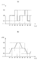
24 is a graph showing an example of an air volume control pattern of a rhythmic wind of a blower according to the present embodiment.
Fig. 25 is a graph showing the control method of the rhythmic wind shown in Fig. 24, where (a) the voltage applied to the motor is set to a fixed value, and (b) the voltage applied to the motor is gradually changed.
26 is (a) a cross-sectional view of a grill portion included in the blower according to the first embodiment, and (b) a cross-sectional view of a grill portion included in the blower according to a modified example.
이하, 본 발명의 실시의 형태에 대하여 도면을 참조하여 상세하게 설명한다. 한편, 도면의 기재에 있어서, 동일 또는 유사한 부분에는 동일 또는 유사한 부호를 붙이고 있다. 단, 도면은 모식적인 것이며, 두께와 평면치수와의 관계, 각 층의 두께의 비율 등은 현실의 것과는 상이함에 유의해야 한다. 따라서, 구체적인 두께나 치수는 이하의 설명을 참작하여 판단해야 한다. 또한, 도면상호간에 있어서도 서로의 치수의 관계나 비율이 상이한 부분이 포함되어 있음은 물론이다.Hereinafter, an embodiment of the present invention will be described in detail with reference to the drawings. In addition, in the description of the drawings, the same or similar reference numerals are attached to the same or similar parts. However, the drawings are schematic, and it should be noted that the relationship between the thickness and the plane dimension, the ratio of the thickness of each layer, etc. are different from those in the real world. Therefore, specific thickness or dimensions should be determined in consideration of the following description. In addition, it goes without saying that parts having different dimensional relationships and ratios between the drawings are included.
[외관][Exterior]
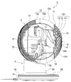
도 1~도 5는, 본 실시의 형태에 따른 송풍기(1)를 나타내는 외관도이고, 도 1은 사시도, 도 2는 정면도, 도 3은 우측면도, 도 4는 상면도, 도 5는 배면도이다. 이 송풍기(1)는, 구면(球面)그릴구조에 의해 풍속강화를 도모함과 함께, 구체형상의 진화형 디자인에 따라 콤팩트하게 보이도록 구성되어 있다.1 to 5 are external views showing the
상세에 대해서는 후술하나, 본 실시의 형태에 따른 송풍기(1)는, 도 1~도 5에 나타내는 바와 같이, 정면측에 송풍구(11)를 가지며, 송풍구(11)에 그릴(12)이 마련된 송풍부(2)와, 송풍부(2)를 지지하는 대좌부(지지부)(3)를 구비하고, 그릴(12)은, 복수의 핀(13)이 소용돌이상으로 마련되며, 복수의 핀(13)의 소용돌이의 중심부(O)에 가까운 내단부(13A)가, 송풍구(11)에 연속하는 외단부(13B)보다 송풍방향(4)으로 돌출되어 있다. 환언하면, 그릴(12) 내의 복수의 핀(13)이 형성되어 있는 부분(13C)의 외단부(13B)에 대해 내단부(13A)가 송풍방향(4)으로 돌출되어 있다. 내단부(13A)란, 소용돌이의 중심부(O)에 가까운 내단측이며, 내단 근처를 포함한다. 외단부(13B)란, 송풍구(11)에 연속하는 외단측의 부분이다. 이에 따라, 바람이 중앙으로 모여(수속하여), 송풍방향의 중앙에 있어서의 풍속을 향상시킬 수 있다. 또한, 송풍구(11)로부터 불어오는 바람(스파이럴기류)의 도달거리를 신장할 수 있다. 그 결과, 실내의 공기를 확실하게 교반할 수 있고, 실내의 온도를 균일화시켜 에너지절약에 공헌할 수 있다.Although it will be described later in detail, the
구체적으로는, 도 6에 나타내는 바와 같이, 복수의 핀(13)의 외단부(13B)에 대한 내단부(13A)의 돌출량(L1)이, 외단부(13B)에 있어서의 전후방향의 핀폭치수(W)보다 크게 설정되어 있는 것이 바람직하다. 여기서 말하는 돌출량(L1)이란, 외단부(13B)의 전단(前端)으로부터 내단부(13A)의 전단까지의 전후방향의 거리에 상당한다. 또한, 핀폭치수(W)란, 핀(13)의 전후방향의 폭치수이다. 여기서는, 핀폭치수(W)가 일정한 핀(13)을 예시하며, 그 핀(13)의 외단부(13B)가 송풍구(11)에 연속하고 있다. 한편, 「복수의 핀(13)의 외단부(13B)에 대한 내단부(13A)의 돌출량」이라는 기재는, 「그릴(12) 내의 복수의 핀(13)이 형성되어 있는 부분(13C)의(외단부(13B)에 대한 내단부(13A)의) 돌출량」이라고 바꿔 말할 수도 있다. 복수의 핀(13)이 형성되어 있는 부분(13C)이란, 그릴(12)로부터 소용돌이의 중심부(O)에 있는 캡(14)을 제외한 부분이다. 이에 따라, 복수의 핀(13)의 외단부(13B)에 대한 내단부(13A)의 돌출량(L1)을 충분히 확보할 수 있어, 바람을 중앙으로 수집시키는 효과를 확실하게 발휘할 수 있다.Specifically, as shown in FIG. 6, the amount of protrusion L 1 of the
또한, 복수의 핀(13)(그릴(12) 내의 복수의 핀(13)이 형성되어 있는 부분(13C))은, 외단부(13B)로부터 소용돌이의 중심부(O)를 향함에 따라 점차 송풍방향(4)으로 돌출되어 있는 것이 바람직하다. 이에 따라, 바람을 중앙으로 수집시키는 효과를 효율좋게 발휘할 수 있어, 확실하게 풍속을 향상시킬 수 있다.In addition, the plurality of fins 13 (the
또한, 복수의 핀(13)(그릴(12) 내의 복수의 핀(13)이 형성되어 있는 부분(13C))은, 송풍방향(4)으로 볼록이 되도록 만곡되어 있는 것이 바람직하다. 이에 따라, 그릴(12)을 만곡상(구면상)으로 함으로써, 한층 더 효율좋게 풍속을 향상시킬 수 있다.Further, it is preferable that the plurality of fins 13 (the
또한, 송풍부(2)의 송풍구(11)가 원형으로 형성되며, 복수의 핀(13)의 외단부(13B)에 대한 내단부(13A)의 돌출량(L1)이, 송풍구(11)의 직경의 20%보다 커지도록 설정되어 있다. 바꿔 말하면, 그릴(12) 내의 복수의 핀(13)이 형성되어 있는 부분(13C)의 내단부(13A)가, 송풍구(11)의 직경의 20%를 초과하여 송풍방향(4)으로 돌출되어 있다. 이에 따라, 바람을 중앙으로 수집시키는 효과를 충분히 발휘할 수 있어, 확실하게 풍속을 향상시킬 수 있다.In addition, the
또한, 송풍부(2)는, 외면을 형성하는 커버(15)와, 커버의 내측에 마련된 원통상의 풍동부(風洞部)(16)를 갖고 있는 것이 바람직하다. 이에 따라, 송풍구(11)로부터 불어오는 바람의 풍속이 안정적이다. 서큘레이터로부터 불어오는 바람은, 소용돌이를 치면서 직진하는 스파이럴기류이며, 선풍기 등에 비해 바람의 지향성 및 직진성이 높다. 풍동부(16)를 마련한다면, 이러한 서큘레이터 특유의 작용인 바람의 지향성 및 직진성을 확보할 수 있다.Moreover, it is preferable that the blowing
또한, 송풍부(2)의 커버(15)는, 그릴(12)을 갖는 프론트커버(15a)와, 프론트커버(15a)에 감착(嵌着)가능한 리어커버(15b)를 가지며, 프론트커버(15a)와 리어커버(15b)가 감착된 감착상태에서 구체형상을 이루는 것이 바람직하다. 이에 따라, 세련된 구체형상으로, 모나지 않고 콤팩트하게 보인다. 또한, 외관의 귀여움이나 멋진 느낌이 업된다.In addition, the
또한, 프론트커버(15a)와 리어커버(15b)는, 감착상태에서 구체형상을 이루도록 반구상으로 형성되며, 프론트커버(15a)의 내측에는, 풍동부(16)를 갖는 풍로형성부재(60)가 마련되고, 풍로형성부재(60)의 일부가 프론트커버(15a)의 후방으로부터 돌출되어 있는 것이 바람직하다. 이에 따라, 감착상태에서 구체형상을 이루는 경우여도, 풍로형성부재(60)의 길이를 확보할 수 있다.In addition, the front cover (15a) and the rear cover (15b) is formed in a hemispherical shape so as to form a spherical shape in the fitting state, and the inside of the front cover (15a), the air passage forming member (60) having a wind tunnel portion (16) Is provided, and it is preferable that a part of the air
또한, 풍로형성부재(60)는, 원통상의 풍동부(16)와, 풍동부(16)의 후단에 연설되어 후방을 향함에 따라 점차 지름이 커지는 확경통부를, 갖고 있는 것이 바람직하다. 확경통부에 대해서는 뒤에 상세하게 설명한다. 이와 같이, 풍로형성부재(60)의 후단이 테이퍼상으로 되어 있으면, 후방으로부터의 공기의 흐름을 원활하게 안내할 수 있다. 또한, 확경통부로부터 풍동부(16)에 들어가는 시점에서, 유로면적의 축소에 따라 유속이 증가하여, 풍속의 상승에 기여할 수 있다.Further, it is preferable that the air
한편, 여기서는, 복수의 핀(13, 13)의 간극로부터 손가락이 들어가는 것을 방지함과 함께 그릴(12)의 보강도 겸해, 각 핀(13)과 교차하는 원형의 링(13R)을 마련한 구성을 예시하고 있는데, 이 링(13R)은 없어도 된다.On the other hand, here, while preventing a finger from entering from the gap between the plurality of
[각 부의 상세][Details of each part]
이하, 도 1~도 5를 이용하여, 본 실시의 형태에 따른 송풍기(1)를 더욱 상세하게 설명한다.Hereinafter, the
이미 설명한 바와 같이, 송풍부(2)의 커버(15)는, 프론트커버(15a)와, 리어커버(15b)를 갖는다. 프론트커버(15a)는, 예를 들어, 폴리프로필렌 등의 합성수지재료로 형성된 반구형상의 커버이며, 전방에 개구된 원형의 송풍구(11)에 구면의 그릴(12)이 마련되어 있다. 리어커버(15b)도, 예를 들어, 폴리프로필렌 등의 합성수지재료로 형성된 반구형상의 커버이다. 리어커버(15b)의 거의 전체면에 걸쳐, 외기를 취입하기 위한 다수의 통기구(21)가 형성되어 있다.As already described, the
그릴(12)은, 예를 들어, 내충격성이 높은 합성수지재료로 형성된 전면(前面)패널이다. 구체적으로는, 소용돌이상의 핀(13)이 소용돌이의 중심부(O)를 향함에 따라 점차 돌출되도록 볼록만곡상으로 형성되어 있다. 그릴(12)의 후방으로부터 바람을 보내, 그릴(12)의 전후방향으로 공기류(바람)가 통과하면, 소용돌이를 치면서 직진하는 스파이럴기류가 발생하게 되어 있다.The
대좌부(3)는, 송풍부(2)를 자유롭게 좌우회전 가능하게 지지하고, 설치면에 재치된다. 대좌부(3)는, 평면에서 볼 때 원형상으로 형성된 대좌하부(31)와, 대좌하부(31)에 감착가능한 대좌상부(32)를 갖는다. 대좌하부(31)도 대좌상부(32)도, 외면을 형성하는 커버는, 예를 들어, 폴리프로필렌 등의 합성수지재료로 형성할 수 있다. 대좌상부(32)의 중심보다 후방에 다리 1개 형상의 지주부(33)를 수직으로 입설(立設)하고, 지주부(33)보다 전방에 조작패널(34)을 배치하고 있다. 여기서는, 지지부(3)로서 대좌부(3)를 예시하고 있는데, 지지부(3)는, 천정 등에 부착가능한 구조로 해도 된다.The
[내부구조][Internal structure]
도 6은, 본 실시의 형태에 따른 송풍기(1)의 단면도이다. 이 도면에 나타내는 바와 같이, 송풍부(2)는, 공기류를 발생시키는 송풍장치로서, 송풍용의 팬(17)과, 팬(17)을 구동하는 모터(18)를 구비한다. 송풍용의 팬(17)으로는, 대풍량의 공기류를 발생시키기 위해, 축류식의 프로펠러팬을 채용하고 있다. 또한, 팬(17)용의 모터(18)로는, 일반적인 AC콘덴서모터를 채용하고 있다. 한편, 팬(17)의 직경(R0)은, 약 120mm~약 240mm로 한다.6 is a cross-sectional view of the
본 실시의 형태에 따른 송풍기(1)는, 좌우회전 및 상하회전을 자동으로 행하기 위해, 좌우회전용의 모터(M1)와 상하회전용의 모터(M2)를 이용하고 있다. 이 2개의 회전용의 모터(M1, M2)로는, 제품 내부에 넣기 위해 사이즈적으로 작은 것이 요구되므로, 싱크로너스모터를 채용하고 있다. 여기서는, 좌우회전 및 상하회전을 자동으로 행하도록 하고 있는데, 이것으로 한정되는 것은 아니다. 예를 들어, 좌우회전만을 자동으로 행하도록 해도 된다.The
[볼록만곡(구면)그릴구조][Convex curved (spherical) grill structure]
이하, 본 실시의 형태에 따른 송풍기(1)가 구비하는 구면그릴구조에 대하여 상세하게 설명한다. 이하에서는, 구면그릴구조의 특징을 명확히 하기 위해, 비교예(평면그릴구조)와 실시예 1, 2(구면그릴구조)를 대비하면서 설명한다.Hereinafter, the spherical grill structure provided in the
(비교예)(Comparative example)
도 7은, 비교예에 따른 송풍기(100)의 사시도이다. 도 1과 동일 또는 유사한 부분에는 동일 또는 유사한 부호를 붙이고 있다. 도 7에 나타내는 바와 같이, 비교예에 따른 송풍기(100)는, 평면그릴구조를 구비하는 서큘레이터이다. 즉, 외형형상이 대략 북상으로 형성된 송풍부(2)를 구비하고, 전방에 개구된 원형의 송풍구(11)에 평면의 그릴(12)이 마련되어 있다. 이러한 평면의 그릴(12)도, 소용돌이상의 복수의 핀(13)을 갖고 있는 점은 동일하다. 프론트커버(15a) 중 그릴(12)을 제외한 부분은, 둥근모양을 띤 원뿔대형상으로 형성되어 있다.7 is a perspective view of a
(실시예 1, 2)(Examples 1 and 2)
도 8은, 본 실시의 형태에 따른 송풍기(1)의 송풍상태를 나타내는 사시도이다. 도 8에 나타내는 바와 같이, 본 실시의 형태에 따른 송풍기(1)는, 구면그릴구조를 구비하는 서큘레이터이다. 그러므로, 그릴(12)로부터 전방을 향해 불어오는 바람에는, 송풍방향(4)의 중앙으로 수속하는 소용돌이를 치도록 회전력이 부여된다. 그 결과, 바람이 중앙으로 모여, 송풍방향(4)의 중앙에 있어서의 풍속을 향상시킬 수 있다. 이하, 본 실시의 형태에 따른 송풍기(1)의 구체예로서, 실시예 1에 따른 송풍기(1a)와 실시예 2에 따른 송풍기(1b)를 들어, 더욱 상세하게 설명한다.8 is a perspective view showing a blowing state of the
도 9(a)는, 실시예 1에 따른 송풍기(1a)가 구비하는 그릴(12)부분의 우측면도이고, 도 9(b)는, 실시예 2에 따른 송풍기(1b)가 구비하는 그릴(12)부분의 우측면도이다. 도 9(a)에 나타내는 바와 같이, 실시예 1에 따른 송풍기(1a)에서는, 예를 들어, 팬(17)의 직경(R0)이 약 150mm인 경우에는, 그릴(12)의 곡률반경(R)을 약 105mm로 하고 있다. 한편, 도 9(b)에 나타내는 바와 같이, 실시예 2에 따른 송풍기(1b)에서는, 예를 들어, 그릴(12)의 곡률반경(R)을 약 92mm로 하고 있다. 그릴(12)의 곡률반경(R)이 다른 점을 제외하고, 실시예 1, 2에 따른 송풍기(1a, 1b)의 기본구조는 동일하다. 예를 들어, 실시예 1에 따른 송풍기(1a)도 실시예 2에 따른 송풍기(1b)도, 외단부(13B)의 전단에 대해 내단부(13A)의 전단이 돌출되어 있는 점이 동일하다.Fig. 9(a) is a right side view of a portion of the
다음에, 비교예, 실시예 1, 2에 따른 작용의 차이에 대하여 설명한다. 도 10(a)는, 비교예에 따른 송풍기(100)의 요부의 단면도이고, 도 10(b)는, 실시예 1에 따른 송풍기(1a)의 요부의 단면도이다. 도면 중의 화살표는, 송풍구(11)로부터 불어오는 바람의 흐름을 나타내고 있다. 도 10(a)에 나타내는 바와 같이, 비교예에 따른 송풍기(100)에서는, 소용돌이상의 복수의 핀(13)이 동일평면 상에 배치되어 있으므로, 송풍방향(4)의 중앙으로 바람이 모이기 어렵다. 한편, 도 10(b)에 나타내는 바와 같이, 실시예 1에 따른 송풍기(1a)에서는, 소용돌이상의 복수의 핀(13)이 입체적으로 배치되어 있으므로, 송풍방향(4)의 중앙으로 바람이 모이기 쉽다. 여기서는, 실시예 1에 따른 송풍기(1a)에 대하여 설명했으나, 실시예 2에 따른 송풍기(1b)에 대해서도, 송풍방향(4)의 중앙으로 바람이 모이기 쉬운 점은 동일하다. 한편, 「송풍방향(4)의 중앙」은, 「송풍구(11)의 중앙의 전방」이나 「팬(17)의 회전축과 평행하며, 또한, 소용돌이의 중심부(O)를 통과하는 직선의 연장선 상」이라고 바꿔 말할 수도 있다.Next, the difference in action according to the comparative examples and examples 1 and 2 will be described. 10(a) is a cross-sectional view of a main part of a
(풍속의 비교)(Comparison of wind speed)
도 11은, 비교예, 실시예 1, 2의 풍속의 시험결과를 나타내는 그래프이다. 세로축은 풍속[m/s]을 나타내고, 가로축은 송풍방향(4)의 중앙을 기준위치「0」으로 한 좌우방향의 거리를 나타내고 있다. 구체적으로는, 가로축에 나타나는 부호 P-4~P4는, 각각, 도 10(b)에 나타나는 부호 P4~P4의 위치에 대응하고 있다. 도 11에 나타내는 바와 같이, 비교예도 실시예 1, 2도, 좌우방향의 거리가 커짐에 따라 풍속이 작아진다. 단, 비교예의 파형은, 송풍방향(4)의 중앙부근이 거의 평탄해지고 있는데에 반해, 실시예 1, 2의 파형은, 송풍방향(4)의 중앙부근이 산형으로 되어 있다. 즉, 송풍방향(4)의 중앙부근에서는, 실시예 1, 2 쪽이 비교예에 비해 풍속이 높게 되어 있다.11 is a graph showing test results of wind speeds of Comparative Examples and Examples 1 and 2; The vertical axis represents the wind speed [m/s], and the horizontal axis represents the distance in the left and right direction with the center of the blowing
실시예 1, 2에 따르면, 그릴(12)을 구면으로 함으로써 송풍방향(4)의 중앙으로 바람이 모여, 풍속을 향상시킬 수 있는 것을 알 수 있었다. 또한, 실시예 1(곡률반경(R) 105)과 실시예 2(곡률반경(R) 92)의 비교로 말하면, 실시예 2의 쪽이 송풍방향(4)의 중앙으로 바람이 와서, 풍속이 약간 증가하는 것을 알 수 있었다.According to Examples 1 and 2, it was found that by making the grill 12 a spherical surface, wind gathers in the center of the blowing
한편, 그릴(12)의 곡률반경(R)은, 예를 들어, 팬(17)의 직경(R0)이 약 150mm인 경우에는, 약 80mm~약 120mm(보다 바람직하게는, 약 90mm~약 110mm)인 것이 바람직하다. 여기서는, 팬(17)의 직경(R0)이 약 150mm인 경우를 전제로 하고 있는데, 팬(17)의 직경(R0)은, 예를 들어, 약 120mm~약 240mm의 범위에서 적당히 변경가능하다. 팬(17)의 직경(R0)이 변하면, 그에 따라 그릴(12)의 곡률반경(R)의 바람직한 범위(약 80mm~약 120mm)도 상사적으로 변하는 것은 말할 필요도 없다.On the other hand, the radius of curvature R of the
(바람의 도달거리의 비교)(Comparison of the wind's reach)
도 12는, 비교예, 실시예 1, 2의 바람의 도달거리의 시험결과를 나타내는 그래프이다. 도 12에 나타내는 바와 같이, 바람의 도달거리[m]는, 비교예가 약 28m인 데에 반해, 실시예 1이 약 30m, 실시예 2가 약 29m였다. 이와 같이, 실시예 1, 2에 따르면, 그릴(12)을 구면으로 함으로써 송풍방향(4)의 중앙으로 바람이 모여, 바람의 도달거리를 향상시킬 수 있는 것을 알 수 있었다. 비교예에서도, 스파이럴기류에 의해 멀리까지 닿는 강한 바람을 실현할 수 있는데, 실시예 1, 2에 따르면, 더욱 그 도달거리를 길게 할 수 있어, 서큘레이터 본래의 공기교반효과가 현저해진다.Fig. 12 is a graph showing test results of wind reach distances of Comparative Examples and Examples 1 and 2. As shown in Fig. 12, the wind distance [m] was about 28 m in Example 1 and about 29 m in Example 2, while the comparative example was about 28 m. As described above, according to Examples 1 and 2, it was found that by making the grill 12 a spherical surface, the wind gathers in the center of the blowing
(팬과 그릴의 상관관계)(Correlation between pan and grill)
도 6에 나타내는 바와 같이, 그릴(12)의 곡률반경을 R, 팬(17)의 직경을 R0, 송풍부(2)의 외경을 R1, 송풍구(11)의 직경(풍동부(16)의 외경)을 R2로 한다. 원통상의 풍동부(16)는, 근소하게 지름이 확대·축소되어도 된다.6, the radius of curvature of the
먼저, 팬(17)의 직경(R0)이 약 150mm인 경우, 그릴(12)의 곡률반경(R)의 바람직한 범위는 약 80mm~약 120mm(보다 바람직하게는, 약 90mm~약 110mm)이고, 실측값은 약 105mm이다. 팬(17)의 직경(R0)과 그릴(12)의 곡률반경(R)의 관계로 말하면, 그릴(12)의 곡률반경(R)의 바람직한 범위는, R/R0=약 53.3%~약 80.0%(보다 바람직하게는, 약 60.0%~약 73.3%)를 만족하는 범위라고 말할 수 있다.First, when the diameter (R 0 ) of the
그릴(12)의 곡률반경(R)이 하한값 미만인 경우, 송풍부(2)에 있어서의 그릴(12)이 찌그러진 형상이 된다. 여기서 말하는 하한값이란, 팬(17)의 직경(R0)의 약 53.3%(보다 바람직하게는, 약 60.0%)이다. 한편, 그릴(12)의 곡률반경(R)이 상한값을 초과하는 경우, 풍속상승의 효과가 충분히 얻어지지 않는다. 여기서 말하는 상한값이란, 팬(17)의 직경(R0)의 약 80.0%(보다 바람직하게는, 약 73.3%)이다.When the radius of curvature (R) of the grill (12) is less than the lower limit, the grill (12) in the air blower (2) is crushed. The lower limit value here is about 53.3% (more preferably, about 60.0%) of the diameter R 0 of the
또한, 팬(17)의 직경(R0)이 약 150mm인 경우, 송풍부(2)의 외경(R1)의 바람직한 범위는 약 160mm~약 240mm이다. 송풍부(2)의 외경(R1)과 팬(17)의 직경(R0)의 관계로 말하면, 송풍부(2)의 외경(R1)의 바람직한 범위는, R1/R0=약 107%~약 160%를 만족하는 범위라고 말할 수 있다. 송풍부(2)는 구형이기 때문에, 송풍부(2)의 외경(R1)은 그릴(12)의 곡률반경(R)의 약 2배가 된다.In addition, when the diameter R 0 of the
송풍부(2)의 외경(R1)이 팬(17)의 직경(R0)의 약 107% 미만인 경우, 팬(17)과 풍동부(16)의 클리어런스를 확보할 수 없어, 팬(17)과 풍동부(16)의 내면이 접촉될 우려가 있고, 제작도 곤란하다. 한편, 송풍부(2)의 외경(R1)이 팬(17)의 직경(R0)의 약 160%를 초과하는 경우, 송풍부(2)의 사이즈가 과대해지고, 머리만 커서 대좌부(3)와의 밸런스가 무너진다.When the outer diameter (R 1 ) of the ventilation part (2) is less than about 107% of the diameter (R 0 ) of the
또한, 팬(17)의 직경(R0)이 약 150mm인 경우, 송풍구(11)의 직경(R2)의 바람직한 범위는 약 155mm~약 175mm이다. 송풍구(11)의 직경(R2)과 팬(17)의 직경(R0) 의 관계로 말하면, 송풍구(11)의 직경(R2)의 바람직한 범위는, R2/R0=약 103%~약 117%를 만족하는 범위라고 말할 수 있다. 송풍구(11)의 직경(R2)를 작게 하면, 풍동부(16)의 길이를 확보할 수 있는 이점이 있다.In addition, when the diameter R 0 of the
송풍구(11)의 직경(R2)이 팬(17)의 직경(R0)의 약 103% 미만인 경우, 팬(17)과 풍동부(16)의 클리어런스를 확보할 수 없어, 접촉의 우려가 있고, 제작도 곤란하다. 한편, 송풍구(11)의 직경(R2)이 팬(17)의 직경(R0)의 약 117%를 초과하는 경우, 구형의 송풍부(2) 중에서 풍동부(16)의 길이를 확보할 수 없어, 불어오는 바람의 지향성과 직진성을 유지하는 것이 곤란하다.If the diameter (R 2 ) of the air outlet (11) is less than about 103% of the diameter (R 0 ) of the fan (17), the clearance between the fan (17) and the wind tunnel (16) cannot be secured, and there is a risk of contact. There is, and it is difficult to manufacture. On the other hand, when the diameter (R 2 ) of the air outlet (11) exceeds about 117% of the diameter (R 0 ) of the fan (17), it is possible to secure the length of the wind tunnel section (16) among the spherical air blow sections (2). It is not possible, and it is difficult to maintain the directivity and straightness of the blowing wind.
송풍구(11)의 직경(R2)과 송풍부(2)의 외경(R1)의 관계로 말하면, 송풍구(11)의 직경(R2)의 바람직한 범위는, R2/R1=약 74%~약 83%를 만족하는 범위라고 말할 수도 있다. 이와 같이 R2/R1이 비교적 작은 경우는, 송풍부(2)의 정면에서 봤을 때 차지하는 송풍구(11)의 면적이 작게 보이는 효과가 있다.That is in relation to the outside diameter (R 1) having a diameter (R 2) and the blower (2) of the
송풍구(11)의 직경(R2)이 송풍부(2)의 외경(R1)의 약 74% 미만인 경우, 팬(17)과 풍동부(16)의 클리어런스를 확보할 수 없어, 접촉의 우려가 보다 높아진다. 한편, 송풍구(11)의 직경(R2)이 송풍부(2)의 외경(R1)의 약 83%를 초과하는 경우, 구형의 송풍부(2) 중에서 풍동부(16)의 길이를 확보할 수 없어, 불어오는 바람의 지향성과 직진성을 유지하는 것이 보다 곤란해진다.If the diameter (R 2 ) of the air outlet (11) is less than about 74% of the outer diameter (R 1 ) of the air outlet (2), the clearance between the fan (17) and the wind tunnel (16) cannot be secured, and there is a concern of contact. Becomes higher than On the other hand, when the diameter (R 2 ) of the ventilating
[구체디자인+내부의 풍동부][Concrete design + interior wind tunnel]
송풍부(2)는, 세련된 구체형상이기 때문에, 모나지 않고 콤팩트하게 보인다. 또한, 외관의 귀여움이나 멋진 느낌이 업된다. 한편, 송풍기(1)로부터 불어오는 바람의 풍속을 안정시키기 위해서는, 일정길이의 풍동부(16)가 필요하다. 이에, 본 실시의 형태에 따른 송풍기(1)에서는, 이하의 구성을 채용하고 있다.Since the
도 13은, 본 실시의 형태에 따른 송풍기(1)가 구비하는 풍로형성부재(60)의 사시도이다. 도 13에 나타내는 바와 같이, 풍로형성부재(60)는, 풍로를 형성하는 부재이며, 그릴(12)과 풍동부(16)와 확경통부(19)를 갖는다. 그릴(12)과 풍동부(16)와 확경통부(19)를 합성수지재료로 일체성형함으로써, 풍로형성부재(60)를 형성하고 있다.13 is a perspective view of the air
풍동부(16)는, 팬(17)의 레이디얼 외방에 마련된 원통상의 부재이며, 풍동부(16)의 내경은, 송풍구(11)의 대경과 대략 동일하다.The
확경통부(19)는, 리어커버(15b)와 감합하는 부분이며, 후방으로 감에 따라 점차 지름이 커지는 테이퍼통상의 부재이다. 확경통부(19)의 최후단(19a)에는, 리어커버(15b)와 계합하는 복수의 계지조(係止爪)(19b)가 마련되어 있다.The
풍동부(16)로부터 확경통부(19)에 걸쳐, 그 외주면에 복수의 보강리브(19c)를 직각으로 세워, 확경통부(19)의 강도를 확보하고 있다. 보강리브(19c)의 외연은, 외장구면커버부재(15C)의 내측의 면에 당접하도록 형성되어 있다.A plurality of reinforcing
풍로형성부재(60)의 외측에 외장구면커버부재(15C)를 부착하면, 그릴(12)의 전면(前面)(복수의 핀(13)의 전단면)과 외장구면커버부재(15C)의 외주면이 연속한 구면을 구성하게 된다.When the exterior spherical cover member 15C is attached to the outside of the air
풍동부(16)와 그릴(12)이 일체성형됨으로써, 풍동부(16)와 그릴(12)과의 연결부의 강도를 확보하면서, 부품점수의 감소, 비용절감을 도모하는 것이 가능하다.Since the
또한, 그릴(12)의 전면(복수의 핀(13)의 전단면)과, 외장구면커버부재(15C)의 외주면이 연속한 구면을 구성함으로써, 송풍부(2)에 있어서의 그릴(12)과 외장구면커버부재(15C) 사이에 단차가 없이, 아름다운 구체형상으로 할 수 있어, 미관을 향상시킬 수 있다.Further, the front surface of the grill 12 (the front end surface of the plurality of pins 13) and the outer peripheral surface of the exterior spherical cover member 15C constitute a continuous spherical surface, so that the
외장구면커버부재(15C)의 내측에 풍동부(16)를 마련함으로써, 불어오는 바람의 지향성과 직진성이 향상되고, 서큘레이터로서의 성능이 안정된다.By providing the
(풍로형성부재)(Pair path forming member)
도 14는, 본 실시의 형태에 따른 송풍기(1)가 구비하는 풍로형성부재(60)의 단면도이다. 이 도면에 나타내는 바와 같이, 풍로형성부재(60) 본체의 길이를 L0, 그릴(12)의 돌출량을 L1, 풍동부(16)의 길이를 L2, 확경통부(19)의 길이를 L3, 그릴(12)의 곡률반경을 R, 확경통부(19)의 내주면의 테이퍼각도를 θ로 한다. 풍로형성부재(60) 본체의 길이(L0)는, 그릴(12)의 선단으로부터 확경통부(19)의 후단까지의 길이이며, L0=L1+L2+L3이 된다. 이하에서도, 팬(17)의 직경(R0)이 약 150mm인 경우를 전제로 한다. 팬(17)의 직경(R0)이 변하면, 그에 따라 각 부의 크기도 상사적으로 변하는 것은 말할 필요도 없다.14 is a cross-sectional view of the air
팬(17)의 직경(R0)이 약 150mm인 경우, 풍동부(16)의 길이(L2)의 바람직한 범위는, 약 45mm~약 60mm이고, 실측값은 약 50mm이다. 풍동부(16)의 길이(L2)의 바람직한 범위는 팬(17)의 직경(R0)(약 150mm)의 약 30%~약 40%라고 말할 수도 있다. 풍동부(16)를 길게 하면, 바람의 지향성 및 직진성을 확보할 수 있다.When the diameter R 0 of the
풍동부(16)의 길이(L2)가, 팬(17)의 직경(R0)의 약 30%(약 45mm) 미만인 경우, 풍동부(16)가 과소해져, 바람의 지향성 및 직진성을 확보할 수 없다. 한편, 풍동부(16)의 길이(L2)가, 팬(17)의 직경(R0)의 약 40%(약 60mm)를 초과하는 경우, 그릴(12)의 돌출량(L1)이나 확경통부(19)의 길이(L3)가 작아져, 풍속상승의 효과가 충분히 얻어지지 않는다.When the length (L 2 ) of the
또한, 풍로형성부재(60) 본체의 길이(L0)는, 그릴(12)의 곡률반경(R)(약 105mm)보다 크게 설정되어 있다. 이에 따라, 풍로형성부재(60)의 후단부(확경통부(19))가 반구상의 프론트커버(15a)로부터 후방으로 돌출되고, 풍로형성부재(60)의 후단부가 리어커버(15b)에 장입되어 있다. 풍로형성부재(60) 본체의 길이(L0)가 길수록, 풍동부(16)의 길이(L2)를 확보하기 쉬운데, 그릴(12)을 구면상으로 형성하고 있으므로, 풍동부(16)를 전방으로 연장하여 길이(L2)를 크게 할 수 없다. 본 실시의 형태에서는, 풍로형성부재(60) 본체의 길이(L0)를 그릴(12)의 곡률반경(R)보다 크게 설정하여, 풍동부(16)의 후방의 확경통부(19)의 일부를 리어커버(15b)에 장입함으로써, 풍동부(16)의 길이(L2)를 확보하고 있다. 또한, 확경통부(19)의 길이(L3)도 충분히 확보할 수 있다.In addition, the length L 0 of the main body of the air
또한, 확경통부(19)는, 테이퍼각도θ가 15도~30도로 설정되어 있다. 이와 같이, 풍로형성부재(60)의 후단의 확경통부(19)를 각도 15도~30도의 테이퍼상으로 함에 따라, 후방으로부터의 공기의 흐름을 원활하게 안내할 수 있다. 또한, 확경통부(19)로부터 풍동부(16)에 들어가는 시점에서, 유로면적의 축소에 따라 유속이 증가하여, 풍속을 상승시키는 것이 가능하다.Moreover, the taper angle [theta] of the diameter
확경통부(19)의 테이퍼각도θ가 15도 미만인 경우, 확경통부(19)로부터 풍동부(16)에 들어가는 시점에서, 유로면적의 축소에 의한 유속상승의 효과를 얻기 어려워진다. 한편, 테이퍼각도θ가 30도를 초과하는 경우, 확경통부(19)에 있어서의 통풍저항이 커지기 때문에, 후방으로부터의 공기의 흐름이 원활해지지 않을 우려가 있다.When the taper angle θ of the diaphragm
(팬과 풍로형성부재의 관계)(Relationship between fan and stove forming member)
도 15에 있어서, 송풍기(1) 내를 흐르는 공기(61)의 유로를 나타내고 있다. 송풍기(1) 내를 흐르는 공기(61)는, 확경통부(19)로부터 풍동부(16)에 들어가는 시점에서, 유로면적의 축소에 따라 유속이 증가한다. 이에 따라, 송풍구(11)로부터 불어오는 바람의 풍속의 상승에 기여하고 있다. 한편, 도 15에 나타내는 바와 같이, 풍로형성부재(60)가 팬(17)의 외측을 포위하고, 팬(17)의 후단위치로부터 풍로형성부재(60)가 뒤로 연장되어 있다.In FIG. 15, a flow path of the
[전기케이블의 배선][Electrical cable wiring]
도 16 및 도 17은, 본 실시의 형태에 따른 송풍기(1)의 내부구조를 나타내고 있다. 구체적으로는, 도 16은, 송풍부(2)의 중심으로부터 좌측에서 절단한 경우의 단면도이고, 도 17은, 커버(15)와 풍로형성부재(60)를 분리하여 좌경사 후방으로부터 내려다본 경우의 사시도이다.16 and 17 show the internal structure of the
도 16 및 도 17에 나타내는 바와 같이, 대좌부(3)로부터 세워 올린 지주(70)로 모터커버(71)를 양 옆으로부터 끼우고, 이 끼운 위치를 상하회전의 축(72)으로 하여, 송풍부(2)가 대좌부(3)에 대해 상하회전을 행한다. 이에, 모터커버(71)에 수용되는 팬(17)용의 모터(18)(도 6 참조)나 상하회전용의 모터(M2)(도 6 참조)에 접속되는 전기케이블(73)을 상하회전의 축(72) 상으로부터 인출해도 된다. 상하회전의 축(72) 상으로부터 인출된 전기케이블(73)은, 대좌부(3)의 상면(35)에 형성된 개구(36)로부터 대좌부(3)의 내부에 취입된다. 전기케이블(73)이 지주(70)의 적당한 위치에 고정되어 있어도 좋다. 이와 같이 상하회전의 회전중심으로 전기케이블(73)을 통과하는 구성에 따르면, 상하회전시에 전기케이블(73)에 비틀림 힘이 가해지지 않으므로, 전기케이블(73)의 단선을 방지할 수 있다.As shown in Figs. 16 and 17, the
[상하회전기구][Up and down rotation mechanism]
도 18 및 도 19는, 본 실시의 형태에 따른 송풍기(1)의 내부구조를 나타내고 있다. 구체적으로는, 도 18은, 송풍부(2)의 중심으로부터 우측에서 절단한 경우의 단면도이고, 도 19는, 커버(15)와 풍로형성부재(60)를 분리하여 우경사 후방으로부터 내려다본 경우의 사시도이다.18 and 19 show the internal structure of the
또한, 도 18 및 도 19에 나타내는 바와 같이, 상하회전용의 모터(M2)의 출력축(94)이 상하회전의 링크기구(90)를 개재하여 지주(70)에 접속되어 있다. 구체적으로는, 링크기구(90)는, 상하회전용의 모터(M2)의 출력축(94)에 고정된 요동아암부재(91)와, 지주(70)에 고정된 고정부재(93)와, 일단부가 요동아암부재(91)에 추착(樞着)되고, 타단부가 고정부재(93)에 추착된 궁형의 링크부재(92)를 구비한다. 요동아암부재(91)와 링크부재(92) 사이에 고무와셔(95)가 끼워지고, 링크부재(92)와 고정부재(93) 사이에 고무와셔(96)가 끼워져도 된다. 이에 따라, 고무와셔(95, 96)로 진동이 흡수되기 때문에, 싱크로너스모터(상하회전용의 모터(M2))의 백래쉬 및 부재(91, 92, 93) 간의 클리어런스에 의한 링크기구(90)의 이음을 방지할 수 있다. 한편, 2개소의 고무와셔(95, 96)의 일방을 생략해도 된다.In addition, as shown in Figs. 18 and 19, the
[조작패널][Control Panel]
도 20은, 본 실시의 형태에 따른 송풍기(1)가 구비하는 조작패널(34)의 평면도이다. 조작패널(34)에는, 도 20에 나타내는 바와 같이, 전원버튼(34a), 전원끄기타이머버튼(34b), 풍량버튼(34c), 리듬버튼(34d), 회전버튼(34e) 등이 포함된다. 전원버튼(34a)은, 전원의 끔/켬을 설정하기 위한 버튼이다. 전원끄기타이머버튼(34b)은, 전원끄기타이머를 설정하기 위한 버튼이다. 풍량버튼(34c)은, 송풍부(2)의 풍량조절을 행하기 위한 버튼으로서, 압하될 때마다, 풍량의 강약설정을 미풍·약·중·강·터보 순으로 5단계로 전환한다. 리듬버튼(34d)은, 후술하는 리듬풍을 설정하기 위한 버튼이다. 회전버튼(34e)은, 상하회전 및 좌우회전의 온/오프를 설정하기 위한 버튼이다.Fig. 20 is a plan view of an
[리어커버][Rear cover]
다음에, 도 5를 참조하면서, 리어커버(15b)에 대하여 더욱 상세하게 설명한다. 이미 설명한 바와 같이, 리어커버(15b)의 거의 전체면에 걸쳐, 외기를 취입하기 위한 다수의 통기구(21)가 형성되어 있다. 본 실시의 형태에서는, 리어커버(15b)의 모터후방개소에 풍공(風孔)(21a)을 추가하고 있다. 이에 따라, 모터(18)가 팬(17)을 구동하고 있을 때에, 모터후방개소의 풍공(21a)으로부터도 외기가 취입되므로, 풍량을 보다 많이 확보할 수 있을 뿐 아니라, 모터(18)가 스스로 발생시키는 공기류에 의해 냉각효과를 일으켜, 발열대책이 되기도 한다.Next, with reference to FIG. 5, the
[좌우회전기구][Left and right rotation mechanism]
도 21은, 본 실시의 형태에 따른 송풍기(1)가 구비하는 좌우회전기구(43)를 나타내는 단면도이다. 도 21에 나타내는 바와 같이, 대좌부(3)는, 내부가 공동(空洞)으로 되어 있으며, 그 공동 내부에 좌우회전기구(43)가 수납되어 있다. 좌우회전기구(43)는, 대좌상부(32)에 고정된 수지제의 고정판(41)과, 인서트성형으로 고정판(41)에 일체화된 중심축(42)과, 고정판(41)의 상면에 고정된 회전용의 모터(M1)를 구비한다. 중심축(42)의 하단이 삽입되는 수지제의 베어링부재(부쉬)(44)를 구비하고, 이 베어링부재(44)의 하단내주부에는, 계지조(44a)가 일체성형되어 있다. 중심축(42)의 하단외주부에는 절결홈(42a)이 형성되며, 절결홈(42a)에 계지조(44a)가 압입되어 있다.Fig. 21 is a cross-sectional view showing the left and
도 22는, 본 실시의 형태에 따른 송풍기(1)가 구비하는 대좌부(3)의 분해도이다. 이하, 도 22를 이용하여, 좌우회전기구(43)를 더욱 상세하게 설명한다.22 is an exploded view of the
이미 설명한 바와 같이, 대좌부(3)는, 내부가 공동으로 되어 있으며, 그 공동 내부에 좌우회전기구(43)가 수납되어 있다. 좌우회전기구(43)는, 고정판(41)과, 고정판(41)의 상면에 고정된 회전용의 모터(M1)(도 21 참조)와, 회전모터(M1)의 출력축(43E)에 고정된 편심캠(43A)과, 대좌하부(31)에 고정되는 고정축(43D)과, 일단부가 편심캠(43A)에 추착되고, 타단부가 고정축(43D)에 추착된 궁형의 연결링크(43B)를 구비한다.As already explained, the inside of the
또한, 고정판(41)은, 대좌상부(32)에 고정되며, 중심축(42)은, 베어링부재(44)에 선회가능하게 삽입된다. 회전용의 모터(M1)(출력축(43E)에 고정된 편심캠(43A)을 포함한다)와 고정축(43D)은, 각각 중심축(42)으로부터 이격된 위치에 마련되어 있다.Further, the fixing
또한, 대좌하부(31)에 개공(開孔)된 축삽입구멍(47)에는, 하단내주부에 계지조(44a)가 형성된 원통상의 베어링부재(44)가 삽입된다. 이 베어링부재(44)에는 중심축(42)이 삽입된다. 중심축(42)의 하단외주부에는 절결홈(42a)이 형성되어 있으며, 그 절결홈(42a)에 계지편이 되는 계지조(44a)가 압입된다. 베어링부재(44)의 하부에 코드폴더(45)를 부착하고, 대좌하부(31) 하면의 개구부(31b)에 보텀캡(46)으로 덮개를 하도록 되어 있다.Further, in the
또한, 고정판(41)과 중심축(42)의 상단부를 인서트성형하고, 중심축(42)에 의해 대좌상부(32)와 대좌하부(31)를 연결함과 함께, 중심축(42)의 베어링부재(44)를 대좌하부(31)에 고정하고 있다. 베어링부재(44)를 개재하여 중심축(42)을 축삽입구멍(47)에 삽입하고 있으므로, 중심축(42)과 축삽입구멍(47)과의 클리어런스가 없어지고, 중심축(42)의 선회에 따른 축삽입구멍(47)의 마모나 그것에 기인하는 이음의 발생을 방지할 수 있고, 중심축(42)을 중심으로 한 대좌상부(32)(송풍부(2))의 선회도 원활해진다.In addition, the upper end portion of the fixing
사용자가 조작패널(34)의 회전버튼(34e)을 압하하여 좌우회전을 온하면, 회전용의 모터(M1)의 출력축(43E)에 고정된 편심캠(43A)이 편심회전하고, 편심캠(43A)에 추착된 연결링크(43B)의 일단부가 원운동을 한다. 연결링크(43B)의 타단부는 대좌하부(31)에 고정된 고정축(43D)에 추착되어 있으므로, 이 원운동에 의해 대좌상부(32)와 그 위에 부착된 송풍부(2)가 중심축(42)을 중심으로 원운동의 반경거리에 따라 좌우방향으로 선회(회전)하게 된다.When the user presses the
이와 같이, 본 실시의 형태에 따른 송풍기(1)는, 대좌하부(31)와, 대좌하부(31)의 위에 회전가능하게 마련되는 대좌상부(32)가 중심축(42)을 통과하여 연결되고, 대좌상부(32)의 위에 송풍부(2)가 마련된 송풍기(1)로서, 대좌하부(31)에 베어링부재(44)를 삽입하고, 이 베어링부재(44)에 중심축(42)을 선회가능하게 삽입함과 함께, 대좌상부(32)에 마련된 고정판(41)과 중심축(42)의 상단부를 인서트성형하고 있다. 이에 따라, 연결부의 강도를 확보하면서, 부품점수의 감소, 비용절감을 도모하는 것이 가능하다.As described above, in the
또한, 대좌상부(32)에 마련된 고정판(41)을 수지로 형성하고 있다. 이에 따라, 고정판(41)의 에지(모서리)에 배선이 찰접(擦接)했을 때에, 배선이 손상되는 것을 방지할 수 있다.Further, the fixing
또한, 중심축(42)의 베어링부재(44)의 하단내주부에 계지조(44a)가 수지로 일체성형되어 있다. 이에 따라, 계지조(44a)가 E링의 대체로서 기능하므로, E링을 이용할 필요가 없어져, 부품점수의 감소, 비용절감을 도모하는 것이 가능하다.In addition, a locking
[대좌부의 이음매][Seam of the base]
도 23은, 본 실시의 형태에 따른 송풍기(1)가 구비하는 대좌부(3)의 이음매를 나타내는 단면도이다. 도 23에 나타내는 바와 같이, 대좌하부(31)의 주연의 내측에 환상내벽(31a)이 입설되고, 대좌상부(32)의 주연을 대좌하부(31)의 환상내벽(31a)에 씌우도록 하고 있다. 이에 따라, 대좌상부(32)와 대좌하부(31)의 간극이 환상내벽(31a)에 의해 가려져서 눈에 띄지 않는다. 또한, 상하의 클리어런스에 여유가 생기기 때문에, 좌우회전시에 대좌상부(32)와 대좌하부(31)와의 찰접을 방지할 수 있고, 찰접에 기인하는 이음이 발생하기 어렵다. 나아가, 대좌상부(32)와 대좌하부(31)의 간극을 통해 먼지 등이 대좌부(3)의 내부에 침입하기 어렵다.23 is a cross-sectional view showing the joint of the
[리듬풍의 제어][Rhythm wind control]
본 실시의 형태에 따른 송풍기(1)는, 전원의 ON/OFF, 전원끄기타이머의 동작, 모터(18)의 회전수, 회전의 작동 등을 제어하는 제어부(50)를 구비하고 있다. 제어부(50)는, CPU(Central Processing Unit), ROM(Read Only Memory), RAM(Random Access Memory) 등으로 구성되는 제어기판이다(도 6 참조). 사용자가 조작패널(34)의 리듬버튼(34d)을 압하하여 리듬모드를 온하면, 제어부(50)가 모터(18)의 회전수를 제어함으로써 리듬풍을 실현하도록 되어 있다.The
도 24는, 본 실시의 형태에 따른 송풍기(1)로부터 불어오는 리듬풍의 풍량조절패턴의 일 예를 나타내는 그래프이다. 가로축은 시간을 나타내고, 세로축은 풍량의 강약설정을 나타내고 있다. 도 24에 나타내는 바와 같이, 리듬모드에서는, 단순한 반복이 되지 않도록 약한 바람과 강한 바람을 전환하여, 동요(ゆらぎ)의 효과를 일으켜, 자연풍에 근접하도록 하고 있다.24 is a graph showing an example of an air volume control pattern of a rhythmic wind blowing from the
구체적으로는, 리듬모드에서는, 하기와 같은 20개의 풍량제어(1)~(20)를 반복한다. 즉, 풍량제어(1)~(20)까지 순서대로 실시한다면, 풍량제어(1)로 되돌아가게 되어 있다. 예를 들어, 풍량제어(1)는, 풍량F2의 동작기간을 15초로 설정하고 있는 것을 의미한다. 풍량F1은, 풍량「미풍」에 상당하고, 풍량F2는, 풍량「약」에 상당하고, 풍량F3은, 풍량「중」에 상당해도 된다.Specifically, in the rhythm mode, the following 20 air volume controls (1) to (20) are repeated. That is, if the air volume control (1) to (20) is performed in order, it returns to the air volume control (1). For example, the
(1)풍량F2를 15초→(2)풍량F1을 15초→(3)풍량F2를 15초→(4)풍량F1을 15초→(5)풍량F3을 30초→(6)풍량F1을 30초→(7)풍량F2를 15초→(8)풍량F1을 15초→(9)풍량F3을 30초→(10)풍량F1을 30초→(11)풍량F2를 15초→(12)풍량F1을 15초→(13)풍량F2를 15초→(14)풍량F1을 15초→(15)풍량F3을 30초→(16)풍량F1을 30초→(17)풍량F2를 15초→(18)풍량F1을 15초→(19)풍량F2를 15초→(20)풍량F1을 15초→···(1) Air volume F2 for 15 seconds → (2) Air volume F1 for 15 seconds → (3) Air volume F2 for 15 seconds → (4) Air volume F1 for 15 seconds → (5) Air volume F3 for 30 seconds → (6)
한편, 여기서는, 20개의 풍량제어(1)~(20)를 반복의 1단위로 하고 있는데, 이러한 1단위를 구성하는 풍량제어의 수는 한정되는 것은 아니다. 또한, 리듬풍에 이용하는 풍량으로서 3개의 풍량 F1, F2, F3을 예시하고 있는데, 리듬풍에 이용하는 풍량의 수나 풍량의 강약도 한정되는 것은 아니다. 또한, 풍량제어의 1단위를 15초 혹은 30초로서 예시하고 있는데, 이 단위초수를 증감하는 것은 자유이다.On the other hand, here, 20 air volume controls (1) to (20) are set as one unit of repetition, but the number of air volume controls constituting such one unit is not limited. In addition, although three air volumes F1, F2, and F3 are exemplified as the air volume used for the rhythmic wind, the number of air volumes used for the rhythmic wind and the intensity of the air volume are not limited. In addition, 1 unit of air volume control is illustrated as 15 seconds or 30 seconds, but it is free to increase or decrease this unit number of seconds.
도 25는, 도 24에 나타나는 리듬풍의 제어방법을 나타내는 그래프이다. 가로축은 시간을 나타내고, 세로축은 모터(18)에 인가하는 전압을 나타내고 있다. 도 25(a)에 나타내는 바와 같이, 단위시간(t1~t2, t2~t3, t3~t4, …)의 사이는 모터(18)에 인가하는 전압을 고정값(V2, V2, V3, …)으로 해도 된다. 혹은, 도 25(b)에 나타내는 바와 같이, 모터(18)에 부가하는 전압을 서서히 변화시키고, 풍량의 전환시의 모터(18)의 회전수를 완만하게 변화시켜도 된다. 모터(18)에 부가하는 전압을 서서히 변화시킨다면, 팬(17)에 가해지는 토크가 점차 증대하게 되어, 팬(17)의 공기저항에 의한 모터(18)의 부하가 경감된다. 또한, 모터(18)의 회전수, 즉, 팬(17)의 회전수를 서서히 변화시킨다면, 풍량의 전환을 원활하게 행할 수 있으므로, 보다 자연풍에 근접하게 할 수 있고, 게다가 풍량이 전환될 때의 팬(17)의 소리를 경감할 수 있다.Fig. 25 is a graph showing a method of controlling the rhythmic wind shown in Fig. 24; The horizontal axis represents time, and the vertical axis represents the voltage applied to the
이와 같이, 제어부(50)가, 복수종류의 풍량강약과 단위초수를 (불규칙하게)조합한 복수개의 풍량제어를 구비한 리듬풍량 조절패턴을 반복하도록 제어함으로써, 리듬모드에서는, 단순한 반복이 되지 않도록 약한 바람과 강한 바람을 전환하여, 동요의 효과를 일으켜, 자연풍에 근접하게 할 수 있다.In this way, by controlling the
또한, 제어부(50)는, 리듬풍을 제어하는 경우, 팬(17)을 구동하는 모터(18)의 전압값을 서서히 증가·감소시킨다. 이에 따라, 풍량의 전환을 완만하게 행할 수 있으므로, 보다 자연풍에 근접하게 할 수 있고, 게다가 풍량이 전환될 때의 팬(17)의 소리를 경감할 수 있다.Further, when controlling the rhythmic wind, the
[변형예][Modified example]
도 26(a)는, 실시예 1에 따른 송풍기(1a)가 구비하는 풍로형성부재(60)의 단면도이고, 도 26(b)는, 변형예에 따른 송풍기가 구비하는 풍로형성부재(60c)의 단면도이다. 도 26(a)에 나타내는 바와 같이, 실시예 1에서는, 핀(13)의 전후방향의 핀폭치수(W)는 어느 부분에 있어서도 대략 일정하다. 한편, 도 26(b)에 나타내는 바와 같이, 변형예에서는, 핀(13)의 전후방향의 핀폭치수(W)가 상이하여, 핀(13)의 외단부(13B)로부터 내단부(13A)를 향함에 따라 핀폭치수(W)가 점차 증대하고, 전부의 핀(13)의 후단위치를 송풍구(11)의 위치에 맞추고 있다ㅣ. 즉, 그릴(12)을 이측으로부터 본 경우에 전부의 핀(13)의 높이위치가 평탄해지고 있다. 이러한 변형예에서도, 비교예에 비해 송풍방향(4)의 중앙으로 바람이 모이기 쉽다는 점은 실시예 1, 2와 마찬가지로 기대할 수 있다.Figure 26 (a) is a cross-sectional view of the air
그 밖에, 그릴(12)에 대해서는 다양한 변형이 가능하다. 즉, 그릴(12)은, 복수의 핀(13)이 소용돌이상으로 마련되며, 복수의 핀(13)의 소용돌이의 중심부(O)에 가까운 내단부(13A)가, 송풍구(11)에 연속하는 외단부(13B)보다 송풍방향(4)으로 돌출되어 있으면 된다. 이 조건을 만족하는 그릴(12)을 채용하는 이상, 본 실시의 형태에 포함된다. 예를 들어, 그릴(12)을 측면에서부터 본 경우의 형상으로는, 만곡상 이외에, 2개 산이 있는 형상, 사다리형상, 중앙부만 패인 형상, 계단상, 이슬람사원의 모스크와 닮은 형상, 후지산형상 등, 다양한 형상을 채용할 수 있다.In addition, various modifications are possible for the
[그 밖의 실시의 형태][Other embodiments]
상기와 같이, 몇가지의 실시의 형태에 대하여 기재하였으나, 개시의 일부를 이루는 논술 및 도면은 예시적인 것이며, 한정하는 것으로 이해해서는 안된다. 이 개시로부터 당업자에게는 다양한 대체실시의 형태, 실시예 및 운용기술이 명백해질 것이다.As described above, several embodiments have been described, but the essay and drawings forming a part of the disclosure are illustrative and should not be understood as limiting. From this disclosure, various alternative embodiments, examples, and operation techniques will become apparent to those skilled in the art.
이와 같이, 본 실시의 형태는, 여기서는 기재하고 있지 않은 다양한 실시의 형태 등을 포함한다.As described above, the present embodiment includes various embodiments and the like that are not described herein.
1, 1a, 1b 송풍기
2 송풍부
3 대좌부(지지부)
4 송풍방향
11 송풍구
12 그릴
13 핀
13A 내단부
13B 외단부
13C 복수의 핀이 형성되어 있는 부분
15 커버
15a 프론트커버
15b 리어커버
16 풍동부
19 확경통부
L1 돌출량
W 핀폭치수
O 소용돌이의 중심부1, 1a, 1b blower
2 blower
3 base (support)
4 Ventilation direction
11 Vents
12 grill
13 pin
13A inner end
13B outer end
13C Part where multiple pins are formed
15 covers
15a front cover
15b rear cover
16 Wind East
19 Expansion pain department
L 1 protrusion amount
W pin width
O the heart of the swirl
Claims (9)
상기 송풍부를 지지하는 지지부를 구비하고,
상기 그릴은, 복수의 송풍 안내판이 소용돌이상으로 마련되며,
상기 복수의 송풍 안내판의 상기 소용돌이의 중심부에 가까운 내단부가, 외단부보다 송풍방향으로 돌출되어 있고,
상기 송풍부는, 외면을 형성하는 커버와, 이 커버의 내측에 마련된 원통상의 풍동부를 갖고 있고,
상기 송풍부의 상기 커버는, 상기 그릴을 갖는 프론트커버와, 이 프론트커버에 감착가능한 리어커버를 가지며, 상기 프론트커버와 상기 리어커버가 감착된 감착상태에서 구체형상을 이루는 서큘레이터.
A blower part having a ventilating port on the front side and provided with a grill at the ventilating port,
It has a support for supporting the air blower,
In the grill, a plurality of ventilation guide plates are provided in a vortex shape,
An inner end portion of the plurality of ventilation guide plates protruding from the outer end portion in the blowing direction closer to the central portion of the vortex,
The blower part has a cover forming an outer surface, and a cylindrical wind tunnel part provided inside the cover,
The cover of the air blower has a front cover having the grill and a rear cover that can be fitted to the front cover, and a circulator having a spherical shape in a fitted state in which the front cover and the rear cover are fitted.
상기 복수의 송풍 안내판의 상기 외단부에 대한 상기 내단부의 돌출량이, 상기 외단부에 있어서의 전후방향의 송풍 안내판의 폭치수보다 크게 설정되어 있는 서큘레이터.
The method of claim 1,
A circulator in which an amount of protrusion of the inner end portion of the plurality of air blow guide plates is set to be larger than the width dimension of the air blow guide plate in the front-rear direction of the outer end portion.
상기 복수의 송풍 안내판은, 상기 외단부로부터 상기 소용돌이의 중심부를 향함에 따라 점차 송풍방향으로 돌출되어 있는 서큘레이터.
The method of claim 1,
The plurality of air blowing guide plates gradually protrude in the air blowing direction from the outer end toward the center of the vortex.
상기 복수의 송풍 안내판은, 송풍방향으로 볼록이 되도록 만곡되어 있는 서큘레이터.
The method of claim 3,
The plurality of ventilation guide plates are curved to be convex in the ventilation direction.
상기 송풍부의 상기 송풍구가 원형으로 형성되며,
상기 복수의 송풍 안내판의 상기 외단부에 대한 상기 내단부의 돌출량이, 이 송풍구의 직경의 20%보다 커지도록 설정되어 있는 서큘레이터.
The method according to any one of claims 1 to 4,
The air outlet of the air blower is formed in a circular shape,
The circulator is set so that the amount of protrusion of the inner end portion of the plurality of air blower guide plates is greater than 20% of the diameter of the air outlet.
상기 프론트커버와 상기 리어커버는, 상기 감착상태에서 상기 구체형상을 이루도록 반구상으로 형성되며,
상기 프론트커버의 내측에는, 상기 풍동부를 갖는 풍로형성부재가 마련되고,
이 풍로형성부재의 일부가 상기 프론트커버의 후방으로부터 돌출되어 있는 서큘레이터.
The method of claim 1,
The front cover and the rear cover are formed in a hemispherical shape to achieve the spherical shape in the depressed state,
Inside the front cover, a wind path forming member having the wind tunnel is provided,
A circulator in which a part of the air passage forming member protrudes from the rear of the front cover.
상기 풍로형성부재는, 상기 원통상의 풍동부와, 이 풍동부의 후단에 연설되어 후방을 향함에 따라 점차 지름이 커지는 확경통부를 갖고 있는 서큘레이터.
The method of claim 6,
The air passage forming member has a cylindrical wind tunnel portion, and a circulator having an expanding barrel portion whose diameter gradually increases as it extends to a rear end of the wind tunnel portion and faces rearward.
Priority Applications (1)
| Application Number | Priority Date | Filing Date | Title |
|---|---|---|---|
| KR1020207036362A KR102285658B1 (en) | 2017-09-29 | 2018-09-26 | Blower |
Applications Claiming Priority (5)
| Application Number | Priority Date | Filing Date | Title |
|---|---|---|---|
| JPJP-P-2017-191401 | 2017-09-29 | ||
| JP2017191401 | 2017-09-29 | ||
| JPJP-P-2018-026445 | 2018-02-16 | ||
| JP2018026445A JP6363811B1 (en) | 2017-09-29 | 2018-02-16 | Circulator |
| PCT/JP2018/035578 WO2019065685A1 (en) | 2017-09-29 | 2018-09-26 | Blower |
Related Child Applications (1)
| Application Number | Title | Priority Date | Filing Date |
|---|---|---|---|
| KR1020207036362A Division KR102285658B1 (en) | 2017-09-29 | 2018-09-26 | Blower |
Publications (2)
| Publication Number | Publication Date |
|---|---|
| KR20200033974A KR20200033974A (en) | 2020-03-30 |
| KR102195764B1 true KR102195764B1 (en) | 2020-12-28 |
Family
ID=62976638
Family Applications (4)
| Application Number | Title | Priority Date | Filing Date |
|---|---|---|---|
| KR1020207036362A KR102285658B1 (en) | 2017-09-29 | 2018-09-26 | Blower |
| KR1020217023404A KR102378135B1 (en) | 2017-09-29 | 2018-09-26 | Blower |
| KR1020227008171A KR102495036B1 (en) | 2017-09-29 | 2018-09-26 | Blower |
| KR1020207007294A KR102195764B1 (en) | 2017-09-29 | 2018-09-26 | Circulator |
Family Applications Before (3)
| Application Number | Title | Priority Date | Filing Date |
|---|---|---|---|
| KR1020207036362A KR102285658B1 (en) | 2017-09-29 | 2018-09-26 | Blower |
| KR1020217023404A KR102378135B1 (en) | 2017-09-29 | 2018-09-26 | Blower |
| KR1020227008171A KR102495036B1 (en) | 2017-09-29 | 2018-09-26 | Blower |
Country Status (10)
| Country | Link |
|---|---|
| US (4) | US10859287B2 (en) |
| EP (2) | EP4039982B1 (en) |
| JP (8) | JP6363811B1 (en) |
| KR (4) | KR102285658B1 (en) |
| CN (2) | CN113250984B (en) |
| CA (1) | CA3075731C (en) |
| ES (1) | ES2918125T3 (en) |
| MX (1) | MX2020003184A (en) |
| TW (2) | TWI787519B (en) |
| WO (1) | WO2019065685A1 (en) |
Families Citing this family (17)
| Publication number | Priority date | Publication date | Assignee | Title |
|---|---|---|---|---|
| KR102093412B1 (en) | 2018-03-07 | 2020-03-25 | 엘지전자 주식회사 | Air conditioner |
| JP6960679B2 (en) * | 2018-04-23 | 2021-11-05 | アイリスオーヤマ株式会社 | humidifier |
| JP1640923S (en) * | 2018-10-03 | 2019-09-09 | ||
| TWD202149S (en) * | 2018-10-03 | 2020-01-11 | 日商愛麗思歐雅瑪股份有限公司 | Circulator |
| TWD202151S (en) * | 2018-10-04 | 2020-01-11 | 日商愛麗思歐雅瑪股份有限公司 | Circulator |
| JP6692100B2 (en) * | 2018-10-10 | 2020-05-13 | アイリスオーヤマ株式会社 | Blower |
| CN111622992A (en) * | 2019-02-28 | 2020-09-04 | 施耐德电气It公司 | Fan cover |
| JP1654101S (en) * | 2019-04-19 | 2020-03-02 | ||
| JP1654102S (en) * | 2019-04-19 | 2020-03-02 | ||
| JP7328850B2 (en) * | 2019-09-26 | 2023-08-17 | シャープ株式会社 | Air blower and air blowing method |
| KR102317240B1 (en) * | 2020-04-20 | 2021-10-26 | 주식회사 유니크테크노 | Circulator And Its Motion Control Method |
| JP6858433B2 (en) * | 2020-11-16 | 2021-04-14 | アイリスオーヤマ株式会社 | Blower |
| CN112503030B (en) * | 2020-12-03 | 2023-04-25 | 泛仕达机电股份有限公司 | Noise reduction flow guide grid |
| CN112628179A (en) * | 2020-12-31 | 2021-04-09 | 珠海格力电器股份有限公司 | Air supply device |
| US20220282736A1 (en) * | 2021-03-08 | 2022-09-08 | Macroair Technologies, Inc. | System and kit for attachment to a support structure of a control panel for a high-volume low speed fan |
| CN113775569B (en) * | 2021-09-26 | 2024-04-12 | 浙江银轮机械股份有限公司 | Fan shell and fan |
| CN114087214A (en) * | 2021-11-03 | 2022-02-25 | 广州高标消防设备有限公司 | Axial-flow type fire-fighting smoke exhaust fan |
Citations (5)
| Publication number | Priority date | Publication date | Assignee | Title |
|---|---|---|---|---|
| US4927324A (en) | 1989-01-09 | 1990-05-22 | Vornado Air Circulation Systems, Inc. | Ducted fan |
| JP3174033B2 (en) * | 1998-12-28 | 2001-06-11 | 株式会社エフアイテイ | Rotating disk type article supply device |
| JP2001165088A (en) | 1999-12-13 | 2001-06-19 | Sanki Printing Kk | Electric fan |
| US7530783B1 (en) | 2005-10-28 | 2009-05-12 | Vornado Air Circulation Systems, Inc. | Grill mounting and retaining assembly |
| US20110223016A1 (en) | 2008-09-08 | 2011-09-15 | Vornado Air, Llc | Air circulator |
Family Cites Families (44)
| Publication number | Priority date | Publication date | Assignee | Title |
|---|---|---|---|---|
| US2100994A (en) * | 1936-02-06 | 1937-11-30 | Casco Products Corp | Fan guard |
| FR2523696B1 (en) * | 1982-03-18 | 1988-03-04 | Jeumont Schneider | METHOD FOR THE COOLING OF A MOTOR DRIVING A TURBINE DETERMINING THE EXHAUST OF HOT FUMES AT THE END OF A DUCT AND DEVICE FOR CARRYING OUT SAID METHOD |
| JPS62133993U (en) | 1986-02-17 | 1987-08-24 | ||
| US4856968A (en) * | 1988-02-02 | 1989-08-15 | Armbruster Joseph M | Air circulation device |
| USD312124S (en) * | 1988-11-23 | 1990-11-13 | Vornado Air Circulation Systems, Inc. | Fan |
| US5296769A (en) * | 1992-01-24 | 1994-03-22 | Electrolux Corporation | Air guide assembly for an electric motor and methods of making |
| USD358639S (en) * | 1993-09-30 | 1995-05-23 | Duracraft Corporation | Stand with electrical control unit for a portable fan |
| MX9706055A (en) * | 1996-08-09 | 1998-02-28 | Hunter Fan Co | Blade ring attachment system. |
| USD413664S (en) * | 1997-08-08 | 1999-09-07 | Vornado Air Circulation Systems, Inc. | Fan |
| TW438953B (en) * | 1999-09-20 | 2001-06-07 | Mitsubishi Electric Corp | Blower, blower system and the blowing method of blower system |
| US6364618B1 (en) * | 2000-02-03 | 2002-04-02 | Lakewood Engineering & Mfg. Co. | Fan body assembly |
| CN2782996Y (en) * | 2005-03-11 | 2006-05-24 | 谢森源 | Adjustable air pump |
| USD608437S1 (en) * | 2007-07-20 | 2010-01-19 | Vornado Air Circulation Systems, Inc. | Fan |
| JP2010054084A (en) | 2008-08-26 | 2010-03-11 | Twinbird Corp | Circulator |
| USD599463S1 (en) * | 2008-10-09 | 2009-09-01 | Israel Gary P | Air circulator |
| USD605280S1 (en) * | 2009-02-10 | 2009-12-01 | Tiger Focus Trading Ltd. | Circulator |
| USD621026S1 (en) * | 2009-07-27 | 2010-08-03 | Camair LLC | Set of fan parts |
| USD621025S1 (en) * | 2009-07-27 | 2010-08-03 | Camair LLC | Set of fan parts |
| JP2011122550A (en) * | 2009-12-14 | 2011-06-23 | Toshiba Home Technology Corp | Electric fan |
| CN101761499A (en) * | 2010-03-02 | 2010-06-30 | 美的集团有限公司 | Brushless direct current fan and control method thereof |
| CN102192164A (en) * | 2010-03-08 | 2011-09-21 | 艾美特电器(深圳)有限公司 | Music electric fan and control method thereof |
| CN102312843A (en) * | 2010-07-07 | 2012-01-11 | 南京工程学院 | Rhythm-driven electric fan |
| CN201916224U (en) * | 2011-01-07 | 2011-08-03 | 邝竞安 | Electric fan |
| JP5786440B2 (en) * | 2011-05-11 | 2015-09-30 | 東芝ホームテクノ株式会社 | Fan |
| US10907843B2 (en) * | 2011-11-18 | 2021-02-02 | Broan-Nutone Llc | Ventilating system and method |
| FR2984971B1 (en) * | 2011-12-21 | 2019-08-23 | Seb Sa | CENTRIFUGAL VENTILATION WHEEL, CORRESPONDING FAN AND COOKING APPARATUS INCLUDING SUCH FAN |
| JP3174033U (en) * | 2011-12-21 | 2012-03-01 | 明宙工業股▲ふん▼有限公司 | Fan front cover |
| CN102536864B (en) * | 2012-03-20 | 2015-11-18 | 开勒环境科技(上海)股份有限公司 | A kind of large-scale hanging type industrial fan |
| CN202612148U (en) * | 2012-05-29 | 2012-12-19 | 合一电器(深圳)有限公司 | Turbo fan |
| JP5787841B2 (en) * | 2012-08-07 | 2015-09-30 | 三菱電機株式会社 | Blower and control method |
| USD688368S1 (en) * | 2012-11-30 | 2013-08-20 | Vornado Air, Llc | Air circulator |
| JP6077897B2 (en) * | 2013-03-19 | 2017-02-08 | シャープ株式会社 | Blower |
| DE102014111767A1 (en) * | 2014-08-18 | 2016-02-18 | Ebm-Papst Mulfingen Gmbh & Co. Kg | Axial |
| CN104265665A (en) | 2014-09-26 | 2015-01-07 | 广东又一电器科技有限公司 | Spherical fan |
| USD760370S1 (en) * | 2014-10-27 | 2016-06-28 | O2Cool, Llc | Fan enclosure with spiral grilles |
| JP5702020B1 (en) * | 2014-11-04 | 2015-04-15 | 株式会社Cmc | Electric fan and control method thereof |
| JP2016194275A (en) * | 2015-04-01 | 2016-11-17 | パナソニックIpマネジメント株式会社 | Blower device |
| CN204878014U (en) * | 2015-08-07 | 2015-12-16 | 林远波 | Fan speed adjustment circuit |
| CN205064330U (en) * | 2015-08-18 | 2016-03-02 | 艾美特电器(九江)有限公司 | Fan yaw mechanism and fan |
| CN206190559U (en) * | 2016-08-28 | 2017-05-24 | 王慧欣 | Electric fan |
| CN106351860A (en) * | 2016-10-28 | 2017-01-25 | 桂林大创科技有限公司 | Household fan and controller thereof |
| CN106837832B (en) | 2017-01-22 | 2019-03-22 | 佛山市顺德区新双岭机电科技有限公司 | A kind of novel portable electric fan |
| CN206429441U (en) | 2017-02-07 | 2017-08-22 | 广东世联电器有限公司 | It is a kind of can wide-angle regulation electric fan |
| US11541342B2 (en) * | 2018-03-07 | 2023-01-03 | Lg Electronics Inc. | Indoor unit for air conditioner |
-
2018
- 2018-02-16 JP JP2018026445A patent/JP6363811B1/en active Active
- 2018-05-18 JP JP2018096053A patent/JP6660419B2/en active Active
- 2018-05-18 JP JP2018096054A patent/JP2019065839A/en active Pending
- 2018-05-18 JP JP2018096055A patent/JP6666952B2/en active Active
- 2018-06-28 JP JP2018123074A patent/JP7148955B2/en active Active
- 2018-09-26 MX MX2020003184A patent/MX2020003184A/en unknown
- 2018-09-26 KR KR1020207036362A patent/KR102285658B1/en active IP Right Grant
- 2018-09-26 ES ES18859996T patent/ES2918125T3/en active Active
- 2018-09-26 KR KR1020217023404A patent/KR102378135B1/en active IP Right Grant
- 2018-09-26 US US16/646,983 patent/US10859287B2/en active Active
- 2018-09-26 CA CA3075731A patent/CA3075731C/en active Active
- 2018-09-26 WO PCT/JP2018/035578 patent/WO2019065685A1/en unknown
- 2018-09-26 EP EP22165933.7A patent/EP4039982B1/en active Active
- 2018-09-26 CN CN202110526699.5A patent/CN113250984B/en active Active
- 2018-09-26 EP EP18859996.3A patent/EP3690250B1/en active Active
- 2018-09-26 KR KR1020227008171A patent/KR102495036B1/en active IP Right Grant
- 2018-09-26 CN CN201880059153.XA patent/CN111094755B/en active Active
- 2018-09-26 KR KR1020207007294A patent/KR102195764B1/en active IP Right Grant
- 2018-09-27 TW TW108119530A patent/TWI787519B/en active
- 2018-09-27 TW TW107134119A patent/TWI665418B/en active
-
2019
- 2019-12-13 JP JP2019225329A patent/JP6775262B2/en active Active
-
2020
- 2020-10-27 US US17/081,882 patent/US11402120B2/en active Active
-
2022
- 2022-01-25 US US17/648,877 patent/US11686500B2/en active Active
- 2022-06-24 JP JP2022101923A patent/JP7153411B2/en active Active
- 2022-09-26 JP JP2022152866A patent/JP2022179542A/en active Pending
-
2023
- 2023-05-10 US US18/315,100 patent/US20230272941A1/en active Pending
Patent Citations (5)
| Publication number | Priority date | Publication date | Assignee | Title |
|---|---|---|---|---|
| US4927324A (en) | 1989-01-09 | 1990-05-22 | Vornado Air Circulation Systems, Inc. | Ducted fan |
| JP3174033B2 (en) * | 1998-12-28 | 2001-06-11 | 株式会社エフアイテイ | Rotating disk type article supply device |
| JP2001165088A (en) | 1999-12-13 | 2001-06-19 | Sanki Printing Kk | Electric fan |
| US7530783B1 (en) | 2005-10-28 | 2009-05-12 | Vornado Air Circulation Systems, Inc. | Grill mounting and retaining assembly |
| US20110223016A1 (en) | 2008-09-08 | 2011-09-15 | Vornado Air, Llc | Air circulator |
Also Published As
Similar Documents
| Publication | Publication Date | Title |
|---|---|---|
| KR102195764B1 (en) | Circulator | |
| CN212319882U (en) | Air conditioner indoor unit and air conditioner | |
| KR0124290Y1 (en) | Device for generating anion | |
| CN110285487A (en) | A kind of air conditioner | |
| KR200284214Y1 (en) | The air vent grill for an automobile | |
| CN114110763A (en) | Air conditioner indoor unit and air conditioner |
Legal Events
| Date | Code | Title | Description |
|---|---|---|---|
| A302 | Request for accelerated examination | ||
| E902 | Notification of reason for refusal | ||
| E701 | Decision to grant or registration of patent right | ||
| A107 | Divisional application of patent | ||
| GRNT | Written decision to grant |