KR102141797B1 - Method of manufacturing turbine blades - Google Patents
Method of manufacturing turbine blades Download PDFInfo
- Publication number
- KR102141797B1 KR102141797B1 KR1020197002968A KR20197002968A KR102141797B1 KR 102141797 B1 KR102141797 B1 KR 102141797B1 KR 1020197002968 A KR1020197002968 A KR 1020197002968A KR 20197002968 A KR20197002968 A KR 20197002968A KR 102141797 B1 KR102141797 B1 KR 102141797B1
- Authority
- KR
- South Korea
- Prior art keywords
- treatment
- temperature
- base material
- soldering
- heating
- Prior art date
Links
Images


Classifications
-
- F—MECHANICAL ENGINEERING; LIGHTING; HEATING; WEAPONS; BLASTING
- F01—MACHINES OR ENGINES IN GENERAL; ENGINE PLANTS IN GENERAL; STEAM ENGINES
- F01D—NON-POSITIVE DISPLACEMENT MACHINES OR ENGINES, e.g. STEAM TURBINES
- F01D5/00—Blades; Blade-carrying members; Heating, heat-insulating, cooling or antivibration means on the blades or the members
- F01D5/12—Blades
- F01D5/28—Selecting particular materials; Particular measures relating thereto; Measures against erosion or corrosion
- F01D5/286—Particular treatment of blades, e.g. to increase durability or resistance against corrosion or erosion
-
- B—PERFORMING OPERATIONS; TRANSPORTING
- B23—MACHINE TOOLS; METAL-WORKING NOT OTHERWISE PROVIDED FOR
- B23K—SOLDERING OR UNSOLDERING; WELDING; CLADDING OR PLATING BY SOLDERING OR WELDING; CUTTING BY APPLYING HEAT LOCALLY, e.g. FLAME CUTTING; WORKING BY LASER BEAM
- B23K3/00—Tools, devices, or special appurtenances for soldering, e.g. brazing, or unsoldering, not specially adapted for particular methods
- B23K3/06—Solder feeding devices; Solder melting pans
-
- B—PERFORMING OPERATIONS; TRANSPORTING
- B23—MACHINE TOOLS; METAL-WORKING NOT OTHERWISE PROVIDED FOR
- B23K—SOLDERING OR UNSOLDERING; WELDING; CLADDING OR PLATING BY SOLDERING OR WELDING; CUTTING BY APPLYING HEAT LOCALLY, e.g. FLAME CUTTING; WORKING BY LASER BEAM
- B23K1/00—Soldering, e.g. brazing, or unsoldering
- B23K1/0008—Soldering, e.g. brazing, or unsoldering specially adapted for particular articles or work
- B23K1/0018—Brazing of turbine parts
-
- C—CHEMISTRY; METALLURGY
- C22—METALLURGY; FERROUS OR NON-FERROUS ALLOYS; TREATMENT OF ALLOYS OR NON-FERROUS METALS
- C22C—ALLOYS
- C22C19/00—Alloys based on nickel or cobalt
- C22C19/03—Alloys based on nickel or cobalt based on nickel
- C22C19/05—Alloys based on nickel or cobalt based on nickel with chromium
- C22C19/051—Alloys based on nickel or cobalt based on nickel with chromium and Mo or W
- C22C19/056—Alloys based on nickel or cobalt based on nickel with chromium and Mo or W with the maximum Cr content being at least 10% but less than 20%
-
- C—CHEMISTRY; METALLURGY
- C22—METALLURGY; FERROUS OR NON-FERROUS ALLOYS; TREATMENT OF ALLOYS OR NON-FERROUS METALS
- C22F—CHANGING THE PHYSICAL STRUCTURE OF NON-FERROUS METALS AND NON-FERROUS ALLOYS
- C22F1/00—Changing the physical structure of non-ferrous metals or alloys by heat treatment or by hot or cold working
- C22F1/002—Changing the physical structure of non-ferrous metals or alloys by heat treatment or by hot or cold working by rapid cooling or quenching; cooling agents used therefor
-
- C—CHEMISTRY; METALLURGY
- C22—METALLURGY; FERROUS OR NON-FERROUS ALLOYS; TREATMENT OF ALLOYS OR NON-FERROUS METALS
- C22F—CHANGING THE PHYSICAL STRUCTURE OF NON-FERROUS METALS AND NON-FERROUS ALLOYS
- C22F1/00—Changing the physical structure of non-ferrous metals or alloys by heat treatment or by hot or cold working
- C22F1/10—Changing the physical structure of non-ferrous metals or alloys by heat treatment or by hot or cold working of nickel or cobalt or alloys based thereon
-
- F—MECHANICAL ENGINEERING; LIGHTING; HEATING; WEAPONS; BLASTING
- F01—MACHINES OR ENGINES IN GENERAL; ENGINE PLANTS IN GENERAL; STEAM ENGINES
- F01D—NON-POSITIVE DISPLACEMENT MACHINES OR ENGINES, e.g. STEAM TURBINES
- F01D25/00—Component parts, details, or accessories, not provided for in, or of interest apart from, other groups
-
- F—MECHANICAL ENGINEERING; LIGHTING; HEATING; WEAPONS; BLASTING
- F01—MACHINES OR ENGINES IN GENERAL; ENGINE PLANTS IN GENERAL; STEAM ENGINES
- F01D—NON-POSITIVE DISPLACEMENT MACHINES OR ENGINES, e.g. STEAM TURBINES
- F01D5/00—Blades; Blade-carrying members; Heating, heat-insulating, cooling or antivibration means on the blades or the members
- F01D5/12—Blades
- F01D5/28—Selecting particular materials; Particular measures relating thereto; Measures against erosion or corrosion
- F01D5/288—Protective coatings for blades
-
- F—MECHANICAL ENGINEERING; LIGHTING; HEATING; WEAPONS; BLASTING
- F01—MACHINES OR ENGINES IN GENERAL; ENGINE PLANTS IN GENERAL; STEAM ENGINES
- F01D—NON-POSITIVE DISPLACEMENT MACHINES OR ENGINES, e.g. STEAM TURBINES
- F01D9/00—Stators
- F01D9/02—Nozzles; Nozzle boxes; Stator blades; Guide conduits, e.g. individual nozzles
-
- F—MECHANICAL ENGINEERING; LIGHTING; HEATING; WEAPONS; BLASTING
- F02—COMBUSTION ENGINES; HOT-GAS OR COMBUSTION-PRODUCT ENGINE PLANTS
- F02C—GAS-TURBINE PLANTS; AIR INTAKES FOR JET-PROPULSION PLANTS; CONTROLLING FUEL SUPPLY IN AIR-BREATHING JET-PROPULSION PLANTS
- F02C7/00—Features, components parts, details or accessories, not provided for in, or of interest apart form groups F02C1/00 - F02C6/00; Air intakes for jet-propulsion plants
-
- B—PERFORMING OPERATIONS; TRANSPORTING
- B23—MACHINE TOOLS; METAL-WORKING NOT OTHERWISE PROVIDED FOR
- B23K—SOLDERING OR UNSOLDERING; WELDING; CLADDING OR PLATING BY SOLDERING OR WELDING; CUTTING BY APPLYING HEAT LOCALLY, e.g. FLAME CUTTING; WORKING BY LASER BEAM
- B23K2101/00—Articles made by soldering, welding or cutting
- B23K2101/001—Turbines
-
- B—PERFORMING OPERATIONS; TRANSPORTING
- B23—MACHINE TOOLS; METAL-WORKING NOT OTHERWISE PROVIDED FOR
- B23K—SOLDERING OR UNSOLDERING; WELDING; CLADDING OR PLATING BY SOLDERING OR WELDING; CUTTING BY APPLYING HEAT LOCALLY, e.g. FLAME CUTTING; WORKING BY LASER BEAM
- B23K2103/00—Materials to be soldered, welded or cut
- B23K2103/08—Non-ferrous metals or alloys
-
- F—MECHANICAL ENGINEERING; LIGHTING; HEATING; WEAPONS; BLASTING
- F05—INDEXING SCHEMES RELATING TO ENGINES OR PUMPS IN VARIOUS SUBCLASSES OF CLASSES F01-F04
- F05D—INDEXING SCHEME FOR ASPECTS RELATING TO NON-POSITIVE-DISPLACEMENT MACHINES OR ENGINES, GAS-TURBINES OR JET-PROPULSION PLANTS
- F05D2230/00—Manufacture
- F05D2230/20—Manufacture essentially without removing material
- F05D2230/23—Manufacture essentially without removing material by permanently joining parts together
- F05D2230/232—Manufacture essentially without removing material by permanently joining parts together by welding
- F05D2230/237—Brazing
-
- F—MECHANICAL ENGINEERING; LIGHTING; HEATING; WEAPONS; BLASTING
- F05—INDEXING SCHEMES RELATING TO ENGINES OR PUMPS IN VARIOUS SUBCLASSES OF CLASSES F01-F04
- F05D—INDEXING SCHEME FOR ASPECTS RELATING TO NON-POSITIVE-DISPLACEMENT MACHINES OR ENGINES, GAS-TURBINES OR JET-PROPULSION PLANTS
- F05D2230/00—Manufacture
- F05D2230/40—Heat treatment
-
- F—MECHANICAL ENGINEERING; LIGHTING; HEATING; WEAPONS; BLASTING
- F05—INDEXING SCHEMES RELATING TO ENGINES OR PUMPS IN VARIOUS SUBCLASSES OF CLASSES F01-F04
- F05D—INDEXING SCHEME FOR ASPECTS RELATING TO NON-POSITIVE-DISPLACEMENT MACHINES OR ENGINES, GAS-TURBINES OR JET-PROPULSION PLANTS
- F05D2230/00—Manufacture
- F05D2230/90—Coating; Surface treatment
-
- F—MECHANICAL ENGINEERING; LIGHTING; HEATING; WEAPONS; BLASTING
- F05—INDEXING SCHEMES RELATING TO ENGINES OR PUMPS IN VARIOUS SUBCLASSES OF CLASSES F01-F04
- F05D—INDEXING SCHEME FOR ASPECTS RELATING TO NON-POSITIVE-DISPLACEMENT MACHINES OR ENGINES, GAS-TURBINES OR JET-PROPULSION PLANTS
- F05D2300/00—Materials; Properties thereof
- F05D2300/10—Metals, alloys or intermetallic compounds
- F05D2300/17—Alloys
-
- F—MECHANICAL ENGINEERING; LIGHTING; HEATING; WEAPONS; BLASTING
- F05—INDEXING SCHEMES RELATING TO ENGINES OR PUMPS IN VARIOUS SUBCLASSES OF CLASSES F01-F04
- F05D—INDEXING SCHEME FOR ASPECTS RELATING TO NON-POSITIVE-DISPLACEMENT MACHINES OR ENGINES, GAS-TURBINES OR JET-PROPULSION PLANTS
- F05D2300/00—Materials; Properties thereof
- F05D2300/60—Properties or characteristics given to material by treatment or manufacturing
- F05D2300/611—Coating
Landscapes
- Engineering & Computer Science (AREA)
- Chemical & Material Sciences (AREA)
- Mechanical Engineering (AREA)
- Materials Engineering (AREA)
- General Engineering & Computer Science (AREA)
- Metallurgy (AREA)
- Organic Chemistry (AREA)
- Physics & Mathematics (AREA)
- Thermal Sciences (AREA)
- Crystallography & Structural Chemistry (AREA)
- Combustion & Propulsion (AREA)
- Turbine Rotor Nozzle Sealing (AREA)
Abstract
땜납재가 배치된 터빈 블레이드의 모재를 가열하여 상기 땜납재를 용융시켜 상기 모재에 접합하는 납땜 처리를 행하는 것과, 납땜 처리된 모재를 가열하여 안정화 처리를 행하는 것과, 안정화 처리가 행해진 모재를 가열하여 시효 처리를 행하는 것을 포함하며, 납땜 처리 및 안정화 처리를 하나의 가열 처리로서 행한다.The base material of the turbine blade on which the solder material is disposed is heated to melt the solder material to perform soldering treatment to be bonded to the base material, to heat the soldered base material to perform stabilization treatment, and to heat and stabilize the base material subjected to stabilization treatment. It includes processing, and soldering processing and stabilization processing are performed as one heating process.
Description
본 발명은 터빈 블레이드의 제조 방법에 관한 것이다.The present invention relates to a method of manufacturing a turbine blade.
가스 터빈은 압축기와 연소기와 터빈을 갖고 있다. 압축기는 공기를 취입하여 압축하여 고온 고압의 압축 공기로 한다. 연소기는 이 압축 공기에 대하여 연료를 공급하여 연소시킨다. 터빈은, 차실 안에 복수의 정익(靜翼) 및 동익(動翼)이 교대로 배치되어 있다. 터빈은, 압축 공기의 연소에 의해 발생한 고온 고압의 연소 가스에 의해 동익이 회전한다. 이 회전에 의해, 열에너지가 회전 에너지로 변환된다.Gas turbines have compressors and combustors and turbines. The compressor blows air and compresses it to make compressed air of high temperature and pressure. The combustor supplies fuel to this compressed air for combustion. In the turbine, a plurality of stator blades and rotor blades are alternately arranged in the vehicle cabin. In the turbine, the rotor blade is rotated by a high-temperature, high-pressure combustion gas generated by combustion of compressed air. By this rotation, thermal energy is converted into rotational energy.
정익이나 동익과 같은 터빈 블레이드는 고온하에 노출되기 때문에, 내열성이 높은 금속 재료를 이용하여 형성된다. 터빈 블레이드를 제조하는 경우, 예를 들어 특허문헌 1에 기재되어 있는 바와 같이, 주조나 단조 등에 의해 모재(母材)를 형성하고, 가열하여 용체화 처리(溶體化處理)를 행한다. 그 후, 모재에 땜납재를 배치하여 가열함으로써 납땜 처리를 행하고, 냉각한 후, 안정화 처리 및 시효 처리의 가열 처리를 행한다.Since turbine blades such as stator blades and rotor blades are exposed to high temperatures, they are formed using a metal material having high heat resistance. In the case of manufacturing a turbine blade, for example, as described in Patent Literature 1, a base material is formed by casting, forging, or the like, and heated to perform solution treatment. Thereafter, a soldering material is placed on the base material to be heated by disposing the soldering material, and after cooling, a stabilization process and a aging process heating process are performed.
특허문헌 1에 기재된 제조 방법에 있어서, 안정화 처리에서는, 납땜 처리에 이용되는 땜납재의 액상선 온도(液相線溫度)보다도 높은 온도에서 가열 처리가 행해진다. 따라서 납땜 처리 후의 모재를 안정화 처리하는 경우, 가열에 의해 땜납재가 다시 용융하고, 땜납 탈락이 발생하는 경우가 있다. 이 때문에, 종래 안정화 처리를 행할 때는, 모재에 땜납재를 더하는 작업을 행할 필요가 있어서 수고스러웠다.In the manufacturing method described in Patent Document 1, in the stabilization treatment, heat treatment is performed at a temperature higher than the liquidus temperature of the solder material used for the soldering treatment. Therefore, in the case of stabilizing the base material after the soldering treatment, the soldering material may be melted again by heating, and solder dropping may occur. For this reason, when performing the conventional stabilization treatment, it was difficult to add a solder material to the base material, which was laborious.
본 발명은 상기를 감안하여 이루어진 것이며, 제조 공정에 있어서의 수고를 경감하는 것이 가능한 터빈 블레이드의 제조 방법을 제공하는 것을 목적으로 한다.This invention is made|formed in view of the said, and it aims at providing the manufacturing method of the turbine blade which can reduce the trouble in a manufacturing process.
본 발명에 관한 터빈 블레이드의 제조 방법은, 땜납재가 배치된 터빈 블레이드의 모재를 가열하여 상기 땜납재를 용융시켜 상기 모재에 접합하는 납땜 처리를 행하는 것과, 납땜 처리된 상기 모재를 가열하여 안정화 처리를 행하는 것과, 상기 안정화 처리가 행해진 상기 모재를 가열하여 시효 처리를 행하는 것을 포함하며, 상기 납땜 처리 및 상기 안정화 처리는 하나의 가열 처리로서 행한다.The method for manufacturing a turbine blade according to the present invention performs a soldering treatment by heating the base material of a turbine blade on which solder material is disposed to melt the solder material and joining the base material, and heating the base material subjected to soldering to stabilize it. And performing an aging treatment by heating the base material on which the stabilization treatment has been performed, and the soldering treatment and the stabilization treatment are performed as one heating treatment.
본 발명에 의하면, 납땜 처리 및 안정화 처리를 하나의 가열 처리로서 행하기 때문에, 땜납재를 다시 더하는 작업 자체가 불필요해진다. 이에 의해, 제조 공정에 있어서의 수고를 경감할 수 있다. 또한, 납땜 처리 및 안정화 처리의 2종류의 처리를 집중하여 행하기 때문에, 단시간에 효율적인 처리가 가능해진다.According to the present invention, since the soldering process and the stabilization process are performed as one heating process, the work itself of adding the solder material again becomes unnecessary. Thereby, trouble in a manufacturing process can be reduced. In addition, since two types of treatments, such as soldering treatment and stabilization treatment, are intensively performed, efficient treatment in a short time becomes possible.
또한, 상기 땜납재의 액상선 온도보다도 높고, 또한 상기 모재에 석출한 γ´ 상이 성장하는 제1 온도로서 행해도 좋다.Further, it may be higher than the liquidus temperature of the solder material, and may be performed as the first temperature at which the γ'phase deposited on the base material grows.
본 발명에 의하면, 하나의 가열 처리에 의해 납땜 처리 및 안정화 처리가 병행하여 행해지기 때문에, 효율적으로 가열 처리를 행할 수 있다.According to the present invention, since the soldering treatment and the stabilization treatment are performed in parallel by one heating treatment, the heating treatment can be efficiently performed.
또한, 상기 납땜 처리 및 상기 안정화 처리와 상기 시효 처리를 연속하여 행해도 좋다.Further, the soldering treatment, the stabilization treatment, and the aging treatment may be continuously performed.
본 발명에 의하면, 납땜 처리 및 안정화 처리와 시효 처리를 연속하여 행하기 때문에, 가열 처리 시간의 단축화를 도모할 수 있다.According to the present invention, since the soldering treatment, the stabilization treatment, and the aging treatment are continuously performed, the heat treatment time can be shortened.
또한, 상기 납땜 처리 및 상기 안정화 처리를 상기 제1 온도에서 행한 후, 상기 시효 처리의 가열 온도인 제2 온도로 조정하는 조정 처리를 행해도 좋다.Moreover, after performing the said soldering process and the said stabilization process at the said 1st temperature, you may perform the adjustment process which adjusts to the 2nd temperature which is the heating temperature of the said aging process.
본 발명에 의하면, 하나의 가열 처리 도중에 가열 온도를 제1 온도에서 제2 온도로 조정함으로써 연속하여 가열을 행하기 때문에, 효율적으로 가열 처리를 행할 수 있다.According to the present invention, since heating is continuously performed by adjusting the heating temperature from the first temperature to the second temperature during one heating treatment, the heating treatment can be efficiently performed.
또한, 상기 제2 온도는 상기 제1 온도보다도 낮아도 좋다.Further, the second temperature may be lower than the first temperature.
본 발명에 의하면, 가열 온도를 제1 온도에서 제2 온도로 저하시킴으로써, 납땜 처리 및 안정화 처리를 행한 후의 열을 유효하게 이용할 수 있다.According to the present invention, by lowering the heating temperature from the first temperature to the second temperature, heat after the soldering treatment and stabilization treatment can be effectively used.
또한, 상기 납땜 처리, 상기 안정화 처리 및 상기 시효 처리는 히터를 갖는 소정의 가열로에서 행하고, 상기 조정 처리는 상기 히터를 정지시키는 것, 또는 상기 히터를 정지시키고 상기 가열로 안에 냉각용 기체를 공급함으로써 상기 가열로의 온도를 저하시켜도 좋다.Further, the soldering treatment, the stabilization treatment and the aging treatment are performed in a predetermined heating furnace having a heater, and the adjustment treatment stops the heater, or stops the heater and supplies cooling gas into the heating furnace. By doing so, the temperature of the heating furnace may be lowered.
본 발명에 의하면, 히터를 정지시킴으로써 조정 처리를 행하는 경우에는, 냉각 작업이나 온도 관리 등의 작업 부담이 경감되어 공정을 간소화할 수 있다. 또한, 히터를 정지시키고 가열로 안에 냉각용 기체를 공급함으로써 조정 처리를 행하는 경우에는, 단시간에 가열로의 온도를 저하시킬 수 있다.ADVANTAGE OF THE INVENTION According to this invention, when adjustment processing is performed by stopping a heater, the operation burden, such as a cooling operation and temperature control, is reduced, and a process can be simplified. Further, in the case where the adjustment process is performed by stopping the heater and supplying a cooling gas into the heating furnace, the temperature of the heating furnace can be reduced in a short time.
또한, 상기 조정 처리는 상기 로 속의 온도(爐內溫度)를 상기 제2 온도보다도 낮은 제3 온도로 저하시킨 후, 상기 히터를 작동시켜 상기 로 속의 온도를 상기 제2 온도까지 상승시켜도 좋다.Further, the adjustment process may lower the temperature in the furnace to a third temperature lower than the second temperature, and then operate the heater to raise the temperature in the furnace to the second temperature.
본 발명에 의하면, 제1 온도로부터 제2 온도를 거쳐서 제3 온도로 변화하는 연속한 가열 처리를 효율적으로 행할 수 있다.ADVANTAGE OF THE INVENTION According to this invention, the continuous heating process which changes from 1st temperature to 2nd temperature to 3rd temperature can be performed efficiently.
또한, 상기 모재의 표면에 상기 모재보다도 내산화성이 높은 금속 재료를 이용하여 언더 코트(under coat)를 형성하는 것과, 상기 언더 코트를 형성한 후, 상기 언더 코트의 표면에 톱 코트(top coat)를 형성하는 것을 포함하며, 상기 톱 코트의 형성은 상기 모재에 대하여 상기 납땜 처리 및 상기 안정화 처리를 행한 후에 행하고, 상기 시효 처리는 상기 톱 코트를 형성한 후에 행해도 좋다.Further, on the surface of the base material, an undercoat is formed using a metal material having higher oxidation resistance than the base material, and after the undercoat is formed, a top coat is formed on the surface of the undercoat. And forming the top coat. The top coat may be formed after the brazing treatment and the stabilization treatment are performed on the base material, and the aging treatment may be performed after forming the top coat.
본 발명에 의하면, 언더 코트를 형성한 후, 납땜 처리 및 안정화 처리를 하나의 가열 처리로서 톱 코트의 형성 전에 행하기 때문에, 가열 처리를 단시간에 효율적으로 할 수 있는 동시에 톱 코트의 균열을 억제할 수 있다.According to the present invention, after the undercoat is formed, the soldering treatment and the stabilization treatment are performed as a single heating treatment before the topcoat is formed, so that the heating treatment can be efficiently performed in a short time while suppressing cracking of the topcoat. Can.
또한, 상기 언더 코트의 형성은 상기 납땜 처리 및 안정화 처리를 행한 후에 행해도 좋다.Further, the undercoat may be formed after the soldering treatment and stabilization treatment.
본 발명에 의하면, 납땜 처리 및 안정화 처리를 행한 후에 언더 코트를 형성하고, 그 후 톱 코트를 형성하는 것으로 된다. 이와 같이, 언더 코트를 형성하고 나서 톱 코트를 형성하기까지 열처리 등의 다른 프로세스를 행하지 않기 때문에, 언더 코트의 표면에 이물(異物) 등이 부착되는 것을 억제할 수 있다. 이물 등이 표면에 부착되면, 언더 코트의 앵커 효과(anchor effect)가 저하된다. 이에 대하여, 본 변형예에서는, 이물 등의 부착을 억제함으로써 앵커 효과의 저하를 억제할 수 있다. 이에 의해, 언더 코트와 톱 코트의 밀착성이 저하되는 것을 방지할 수 있다.According to the present invention, the undercoat is formed after the soldering treatment and the stabilization treatment, and then the top coat is formed. In this way, since other processes such as heat treatment are not performed until the top coat is formed and then the top coat is formed, it is possible to suppress foreign matter or the like from adhering to the surface of the undercoat. When foreign matter or the like adheres to the surface, the anchor effect of the undercoat is deteriorated. On the other hand, in this modified example, deterioration of the anchor effect can be suppressed by suppressing adhesion of foreign substances or the like. Thereby, it can prevent that the adhesiveness of an undercoat and a topcoat falls.
또한, 상기 모재의 표면에 상기 모재보다도 내산화성이 높은 금속 재료를 이용하여 언더 코트를 형성하는 것과, 상기 언더 코트를 형성한 후, 상기 언더 코트의 표면에 톱 코트를 형성하는 것을 포함하며, 상기 톱 코트의 형성은, 상기 언더 코트를 형성한 후, 상기 모재에 대하여 상기 납땜 처리 및 상기 안정화 처리와, 상기 시효 처리를 행한 후에 행해도 좋다.Further, the method includes forming an undercoat on a surface of the base material using a metal material having higher oxidation resistance than the base material, and forming a top coat on the surface of the undercoat after forming the undercoat. The top coat may be formed after the undercoat is formed, after the soldering treatment, the stabilization treatment, and the aging treatment are performed on the base material.
본 발명에 의하면, 언더 코트를 형성한 후, 납땜 처리 및 안정화 처리와 시효 처리를 연속하여 톱 코트의 형성 전에 행하기 때문에, 가열 처리를 단시간에 효율적으로 할 수 있는 동시에 톱 코트의 반점(斑点)이나 균열을 억제할 수 있다.According to the present invention, after the undercoat is formed, the soldering treatment, the stabilization treatment, and the aging treatment are successively performed before the topcoat is formed, so that the heating treatment can be efficiently performed in a short time and the top coat spots. Or cracks can be suppressed.
본 발명에 의하면, 제조 공정에 있어서의 수고를 경감하는 것이 가능한 터빈 블레이드의 제조 방법을 제공할 수 있다.ADVANTAGE OF THE INVENTION According to this invention, the manufacturing method of the turbine blade which can reduce the trouble in a manufacturing process can be provided.
도 1은 제1 실시형태에 관한 터빈 블레이드의 제조 방법의 일례를 나타내는 플로 차트이다.
도 2는 납땜 처리 및 안정화 처리를 하나의 가열 처리로서 행하는 경우의 가열 온도의 시간 변화의 일례를 나타내는 그래프이다.
도 3은 제2 실시형태에 관한 터빈 블레이드의 제조 방법의 일례를 나타내는 플로 차트이다.
도 4는 납땜 처리 및 안정화 처리와 시효 처리를 연속하여 행하는 경우의 가열 온도의 시간 변화의 일례를 나타내는 그래프이다.
도 5는 제3 실시형태에 관한 터빈 블레이드의 제조 방법의 일례를 나타내는 플로 차트이다.
도 6은 변형예에 관한 터빈 블레이드의 제조 방법의 일례를 나타내는 플로 차트이다.
도 7은 제4 실시형태에 관한 터빈 블레이드의 제조 방법의 일례를 나타내는 플로 차트이다.
도 8은 납땜 처리 및 안정화 처리와 시효 처리를 연속하여 행하는 경우의 가열 온도의 시간 변화의 다른 예를 나타내는 그래프이다.
도 9는 비교예에 관한 터빈 블레이드의 모재에 대하여 γ´ 상의 석출 상태를 나타내는 현미경 사진을 나타내는 도면이다.
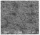
도 10은 실시예 1에 관한 터빈 블레이드의 모재에 대하여 γ´ 상의 석출 상태를 나타내는 현미경 사진을 나타내는 도면이다.
도 11은 실시예 2에 관한 터빈 블레이드의 모재에 대하여 γ´ 상의 석출 상태를 나타내는 현미경 사진을 나타내는 도면이다.1 is a flow chart showing an example of a method for manufacturing a turbine blade according to the first embodiment.
2 is a graph showing an example of the time change of the heating temperature when the soldering treatment and the stabilization treatment are performed as one heating treatment.
3 is a flow chart showing an example of a method of manufacturing a turbine blade according to the second embodiment.
4 is a graph showing an example of a time change of the heating temperature when the soldering treatment, stabilization treatment, and aging treatment are continuously performed.
5 is a flow chart showing an example of a method of manufacturing a turbine blade according to the third embodiment.
6 is a flow chart showing an example of a method of manufacturing a turbine blade according to a modification.
7 is a flow chart showing an example of a method of manufacturing a turbine blade according to the fourth embodiment.
8 is a graph showing another example of the change in time of the heating temperature when the soldering treatment, stabilization treatment, and aging treatment are continuously performed.
9 is a view showing a micrograph showing the precipitation state of the γ'phase with respect to the base material of the turbine blade according to the comparative example.
10 is a view showing a micrograph showing the precipitation state of the γ'phase with respect to the base material of the turbine blade according to Example 1. FIG.
11 is a view showing a photomicrograph showing the precipitation state of the γ'phase with respect to the base material of the turbine blade according to Example 2. FIG.
이하, 본 발명에 관한 터빈 블레이드의 제조 방법의 실시형태를 도면에 기초하여 설명한다. 또한, 이 실시형태에 의해 본 발명이 한정되는 것은 아니다. 또한, 하기 실시형태에 있어서의 구성 요소에는, 당업자가 치환 가능한 동시에 용이한 것, 또는 실질적으로 동일한 것이 포함된다.EMBODIMENT OF THE INVENTION Hereinafter, embodiment of the manufacturing method of the turbine blade which concerns on this invention is demonstrated based on drawing. In addition, this invention is not limited by this embodiment. In addition, the thing in the following embodiment contains the thing which is easy for a person skilled in the art to substitute, and the thing which is substantially the same.
<제1 실시형태><First Embodiment>
도 1은 제1 실시형태에 관한 터빈 블레이드의 제조 방법의 일례를 나타내는 플로 차트이다. 도 1에 나타내는 바와 같이, 제1 실시형태에 관한 터빈 블레이드의 제조 방법은, 예를 들어 가스 터빈의 정익이나 동익과 같은 터빈 블레이드의 모재를 형성하는 공정(단계 S10)과, 모재를 용체화 처리하는 공정(단계 S20)과, 모재에 대하여 납땜 처리 및 안정화 처리를 하나의 가열 처리로서 하는 공정(단계 S30)과, 모재를 시효 처리하는 공정(단계 S40)을 포함한다.1 is a flow chart showing an example of a method for manufacturing a turbine blade according to the first embodiment. As shown in FIG. 1, the manufacturing method of the turbine blade which concerns on 1st Embodiment WHEREIN: The process (step S10) which forms the base material of a turbine blade like a stator blade and a rotor blade of a gas turbine, and the base material is subjected to solution treatment. It includes a process to be performed (step S20), a process of soldering and stabilizing the base material as one heat treatment (step S30), and a step of aging the base material (step S40).
단계(S10)에서는, 정익이나 동익 등의 터빈 블레이드를 구성하는 모재가 형성된다. 터빈 블레이드는 가스 터빈에 있어서 고온하에 노출된다. 이 때문에, 터빈 블레이드를 구성하는 모재는, 내열성이 우수한 합금, 예를 들어 Ni기 합금 등의 재료를 이용하여 형성된다. Ni기 합금으로서는, 예를 들어 Cr: 12.0% 이상 14.3% 이하, Co: 8.5% 이상 11.0% 이하, Mo: 1.0% 이상 3.5% 이하, W: 3.5% 이상 6.2% 이하, Ta: 3.0% 이상 5.5% 이하, Al: 3.5% 이상 4.5% 이하, Ti: 2.0% 이상 3.2% 이하, C: 0.04% 이상 0.12% 이하, B: 0.005% 이상 0.05% 이하를 함유하고, 잔부가 Ni 및 불가피 불순물로 이루어지는 조성의 Ni기 합금 등을 들 수 있다. 또한, 상기 조성의 Ni기 합금에 Zr: 0.001 ppm 이상 5 ppm 이하를 함유해도 좋다. 또한, 상기 조성의 Ni기 합금에 Mg 및/또는 Ca: 1 ppm 이상 100 ppm 이하를 함유해도 좋고, 추가로 Pt: 0.02% 이상 0.5% 이하, Rh: 0.02% 이상 0.5% 이하, Re: 0.02% 이상 0.5% 이하 중 1종 또는 2종 이상을 함유해도 좋으며, 이들 쌍방을 함유해도 좋다.In step S10, a base material constituting a turbine blade such as a stator blade or a rotor blade is formed. Turbine blades are exposed to high temperatures in gas turbines. For this reason, the base material constituting the turbine blade is formed using a material having excellent heat resistance, for example, a Ni-based alloy. As a Ni-based alloy, for example, Cr: 12.0% to 14.3%, Co: 8.5% to 11.0%, Mo: 1.0% to 3.5%, W: 3.5% to 6.2%, Ta: 3.0% to 5.5 % Or less, Al: 3.5% or more and 4.5% or less, Ti: 2.0% or more and 3.2% or less, C: 0.04% or more and 0.12% or less, B: 0.005% or more and 0.05% or less, the remainder consisting of Ni and inevitable impurities And Ni-based alloys having a composition. Moreover, you may contain Zr: 0.001 ppm or more and 5 ppm or less in the Ni-based alloy of the said composition. Further, the Ni-based alloy of the above composition may contain Mg and/or Ca: 1 ppm or more and 100 ppm or less, and further Pt: 0.02% or more and 0.5% or less, Rh: 0.02% or more and 0.5% or less, Re: 0.02% It may contain 1 or 2 or more of 0.5% or less, and may contain both of them.
모재는 상기 재료를 이용하여 주조나 단조 등에 의해 형성된다. 주조에 의해 모재를 형성하는 경우, 예를 들어 보통 주조재(Conventional Casting: CC), 일 방향 응고재(Directional Solidification: DS), 단결정재(Single Crystal: SC) 등의 모재를 형성할 수 있다. 이하, 모재로서 일 방향 응고재가 이용되는 경우를 예로 들어 설명하지만, 이에 한정되는 것은 아니며, 모재가 보통 주조재 또는 단결정재라도 동일한 설명이 가능하다.The base material is formed by casting, forging, or the like using the material. When the base material is formed by casting, for example, a base material such as a conventional casting material (CC), a directional solidification material (DS), or a single crystal material (SC) may be formed. Hereinafter, a case in which a unidirectional coagulating material is used as a base material will be described as an example, but the present invention is not limited thereto, and the same description is possible even if the base material is usually a casting material or a single crystal material.
단계(S20)에 있어서의 용체화 처리는, 전 공정에서 생성된 석출물을 가열에 의해 고용시켜 성분 편석(性分偏析)을 경감시키는 가열 처리이다. 용체화 처리에서는, 예를 들어 1200℃ 정도의 온도에서 모재를 가열한다.The solution treatment in step (S20) is a heat treatment in which the precipitates produced in the previous step are solid-dissolved by heating to reduce component segregation. In the solution treatment, for example, the base material is heated at a temperature of about 1200°C.
단계(S30)에 있어서의 납땜 처리는 모재에 땜납재를 배치한 상태에서 가열함으로써, 땜납재를 모재에 용융시켜 접합하는 처리이다. 땜납재로서는, 예를 들어 BNi-2 상당재(相當材) 등이 이용된다. 이 경우, 땜납재의 고상선 온도(固相線溫度)는, 예를 들어 970℃ 정도이다. 납땜 처리에 이용되는 땜납재의 양에 대해서는, 실험 등을 행함으로써 미리 조정해 둔다. 납땜 처리에서는, 땜납재를 용융시키는 것이 가능한 제1 온도(T1)에서 가열 처리를 행한다. 제1 온도(T1)로서는, 예를 들어 1060℃ 이상 1100℃ 이하의 온도로 할 수 있다.The soldering process in step S30 is a process of melting and bonding the solder material to the base material by heating in a state where the solder material is placed in the base material. As the solder material, for example, a BNi-2 equivalent material or the like is used. In this case, the solidus temperature of the solder material is, for example, about 970°C. The amount of the solder material used in the soldering treatment is adjusted in advance by performing experiments or the like. In the soldering treatment, a heating treatment is performed at a first temperature T1 capable of melting the solder material. As the first temperature T1, for example, the temperature may be 1060°C or higher and 1100°C or lower.
단계(S30)에 있어서의 안정화 처리는 모재를 가열함으로써, 모재에 있어서 금속 간 화합물인 γ´ 상을 성장시켜 γ´ 상의 크기, 형태 등을 구비하는 처리이다. 안정화 처리에서는, 예를 들어 납땜 처리에 있어서의 가열 온도와 동등한 온도인 제1 온도(T1)에서 가열 처리를 행할 수 있다.The stabilization treatment in step (S30) is a treatment having a size, shape, and the like of the γ'phase by heating the base material to grow the intermetallic compound γ'phase in the base material. In the stabilization treatment, for example, the heating treatment can be performed at a first temperature T1, which is a temperature equivalent to the heating temperature in the soldering treatment.
본 실시형태에서는, 단계(S30)에 있어서, 납땜 처리와 안정화 처리를 하나의 가열 처리로서 행한다. 도 2는 단계(S30)에 있어서의 가열 처리의 일례를 나타내는 그래프이다. 도 2의 횡축은 시간을 나타내고, 종축은 온도를 나타내고 있다.In this embodiment, in step S30, the soldering process and the stabilization process are performed as one heating process. 2 is a graph showing an example of the heat treatment in step S30. The horizontal axis in Fig. 2 represents time, and the vertical axis represents temperature.
단계(S30)에서는, 모재에 땜납재를 배치한 상태에서 소정의 가열로에 투입하고, 가열로의 히터를 작동시켜 가열을 개시한다(시각 t1). 가열 개시 후, 먼저 가열로의 로 속의 온도(가열 온도)를 소정의 예열 온도(T0)까지 상승시킨다. 이 예열 온도(T0)는 땜납재의 고상선 온도보다도 낮은 온도로 설정되며, 예를 들어 930℃ 이상 970℃ 이하의 온도로 할 수 있다. 로 속의 온도가 예열 온도(T0)에 도달한 경우(시각 t2), 로 속의 온도의 상승을 정지하고, 소정 시간 당해 예열 온도(T0)에서의 가열 처리(예열 처리)를 행한다. 예열 처리를 행함으로써, 모재 및 땜납재의 온도가 전체적으로 균일하게 상승하고, 각 부위에 있어서의 온도차가 저감한다.In step S30, the solder material is placed in the base material, and then is put into a predetermined heating furnace, and the heater of the heating furnace is operated to start heating (time t1). After starting heating, first, the temperature (heating temperature) in the furnace of the heating furnace is raised to a predetermined preheating temperature T0. This preheating temperature T0 is set to a temperature lower than the solidus temperature of the solder material, and can be, for example, a temperature of 930°C or higher and 970°C or lower. When the temperature in the furnace reaches the preheating temperature T0 (time t2), the rise in the temperature in the furnace is stopped, and heat treatment (preheating treatment) is performed at the preheating temperature T0 for a predetermined time. By performing the preheating treatment, the temperature of the base material and the solder material is uniformly raised as a whole, and the temperature difference at each site is reduced.
예열 처리를 소정 시간 행한 후(시각 t3), 다시 로 속의 온도를 상승시킨다. 로 속의 온도가 제1 온도(T1)에 도달한 경우(시각 t4), 로 속의 온도의 상승을 정지하고, 당해 제1 온도(T1)에서 소정 시간 가열 처리를 행한다. 이 제1 온도(T1)에서의 가열 처리에 의해, 땜납재가 용융하여 모재에 접합된다. 또한, 모재에 있어서 γ´ 상이 성장하여, 당해 γ´ 상의 크기, 형태 등이 구비될 수 있다. 예열 처리를 행한 상태로부터 제1 온도(T1)에서 가열하기 때문에, 모재의 각부가 얼룩 없이 가열되게 된다. 이 때문에, 균일하게 납땜할 수 있는 동시에 모재의 각부에 있어서 γ´ 상이 균일하게 성장한다. 제1 온도(T1)에서의 가열 처리가 소정 시간 행해진 후(시각 t5), 예를 들어 히터를 정지시키고 가열로 안에 냉각용 기체를 공급함으로써 모재의 온도를, 예를 들어 30℃/min 정도의 온도 저하 속도로 소정의 냉각 온도까지 급격히 저하시킨다(급냉). 이 급냉 처리에 의해, γ´ 상의 상태(입경(粒徑) 등)가 유지된다. 그 후, 로 속의 온도가 소정의 냉각 온도까지 저하된 경우(시각 t6), 단계(S30)의 처리가 완료된다. 이와 같이, 본 실시형태에서는, 납땜 처리 및 안정화 처리를 하나의 가열 처리로서 행한다.After the preheating treatment is performed for a predetermined time (time t3), the temperature in the furnace is raised again. When the temperature in the furnace reaches the first temperature T1 (time t4), the rise in temperature in the furnace is stopped, and heat treatment is performed for a predetermined time at the first temperature T1. By the heat treatment at the first temperature T1, the solder material is melted and bonded to the base material. In addition, the γ′ phase grows in the base material, and thus the size, shape, and the like of the γ′ phase may be provided. Since heating is performed at the first temperature T1 from the preheating state, each portion of the base material is heated without staining. For this reason, it is possible to uniformly solder and at the same time the γ'phase grows uniformly in each part of the base material. After the heat treatment at the first temperature T1 is performed for a predetermined time (time t5), for example, by stopping the heater and supplying a cooling gas into the heating furnace, the temperature of the base material is, for example, about 30°C/min. The temperature decreases rapidly to a predetermined cooling temperature (rapid cooling). By this quenching treatment, the state of γ'phase (particle size, etc.) is maintained. Thereafter, when the temperature in the furnace has decreased to a predetermined cooling temperature (time t6), the process of step S30 is completed. Thus, in this embodiment, the soldering process and the stabilization process are performed as one heating process.
단계(S40)에 있어서의 시효 처리는, 안정화 처리를 행한 모재를 가열함으로써, 모재에 있어서, 안정화 처리에서 성장한 γ´ 상을 더욱더 성장시키는 동시에 당해 안정화 처리에서 생긴 γ´ 상보다도 소직경의 γ´ 상을 석출시킨다. 이 소직경의 γ´ 상은 모재의 강도를 증가시킨다. 따라서 시효 처리는 소직경의 γ´ 상을 석출시켜 모재의 강도를 높임으로써, 최종적으로 모재의 강도 및 연성을 조정한다. 즉, 납땜 처리, 안정화 처리 및 시효 처리가 구비됨으로써, γ´ 상의 석출을 조정하고, 강도와 연성을 겸비시킬 수 있다.The aging treatment in step (S40), by heating the base material subjected to the stabilization treatment, further increases the γ'phase grown in the stabilization treatment in the base material, and at the same time, the smaller diameter γ'than the γ'phase generated in the stabilization treatment. Precipitate the phase. The γ´ phase of this small diameter increases the strength of the base material. Therefore, the aging treatment increases the strength of the base material by depositing a γ'phase of a small diameter, and finally adjusts the strength and ductility of the base material. That is, by providing the soldering treatment, stabilization treatment, and aging treatment, it is possible to adjust the precipitation of the γ'phase and combine strength and ductility.
시효 처리에서는, 예를 들어 제1 온도(T1)보다도 낮은 제2 온도(T2)에서 소정 시간 가열 처리를 행한다. 제2 온도(T2)로서는, 예를 들어 830℃ 이상 870℃ 이하의 온도로 할 수 있다. 시효 처리를 소정 시간 행한 후, 가열로의 히터를 정지시키고, 가열로 안에 냉각용 기체를 공급함으로써 모재의 온도를, 예를 들어 30℃/min 정도의 온도 저하 속도로 급격히 저하시킨다(급냉).In the aging treatment, for example, the heating treatment is performed for a predetermined time at a second temperature T2 lower than the first temperature T1. As the second temperature T2, for example, the temperature may be 830°C or higher and 870°C or lower. After the aging treatment is performed for a predetermined time, the heater of the heating furnace is stopped, and the temperature of the base material is rapidly decreased at a temperature drop rate of, for example, about 30°C/min (quench) by supplying a cooling gas into the heating furnace (quench).
이상과 같이, 본 실시형태에서는, 하나의 가열 처리에 의해 납땜 처리와 용체화 처리가 행해지기 때문에, 땜납재를 다시 추가하는 작업 자체가 불필요해진다. 이에 의해 제조 공정에 있어서의 수고를 경감할 수 있다. 또한, 납땜 처리 및 안정화 처리의 2종류의 처리를 집중하여 행하기 때문에, 단시간에 효율적인 처리가 가능해진다.As described above, in this embodiment, since the soldering treatment and the solution treatment are performed by one heating treatment, the operation itself of adding the solder material again becomes unnecessary. Thereby, trouble in a manufacturing process can be reduced. In addition, since two types of treatments, such as soldering treatment and stabilization treatment, are intensively performed, efficient treatment can be achieved in a short time.
<제2 실시형태><Second Embodiment>
도 3은 제2 실시형태에 관한 터빈 블레이드의 제조 방법의 일례를 나타내는 플로 차트이다. 도 3에 나타내는 바와 같이, 제2 실시형태에 관한 터빈 블레이드의 제조 방법은, 예를 들어 터빈 블레이드의 모재를 형성하는 공정(단계 S110)과, 모재를 용체화 처리하는 공정(단계 S120)과, 모재에 대하여 납땜 처리 및 안정화 처리와 시효 처리를 행하는 공정(단계 S130)을 포함한다. 단계(S110) 및 단계(S120)에 대해서는 각각 제1 실시형태의 단계(S10) 및 단계(S20)와 동일하기 때문에 설명을 생략한다.3 is a flow chart showing an example of a method of manufacturing a turbine blade according to the second embodiment. As shown in FIG. 3, the manufacturing method of the turbine blade which concerns on 2nd Embodiment is a process of forming a base material of a turbine blade (step S110), and the process of solution-processing a base material (step S120), for example. And a step of performing a soldering treatment, stabilization treatment, and aging treatment on the base material (step S130). Steps S110 and S120 are the same as steps S10 and S20 of the first embodiment, respectively, and thus descriptions thereof will be omitted.
본 실시형태에서는, 단계(S130)에 있어서, 납땜 처리 및 안정화 처리와 시효 처리를 연속하여 행한다. 도 4는 단계(S130)에 있어서의 가열 처리의 일례를 나타내는 그래프이다. 도 3의 횡축은 시간을 나타내고, 종축은 온도를 나타내고 있다.In this embodiment, in step S130, the soldering treatment, stabilization treatment, and aging treatment are continuously performed. 4 is a graph showing an example of the heat treatment in step S130. The horizontal axis in Fig. 3 represents time, and the vertical axis represents temperature.
단계(S130)에서는, 제1 실시형태와 동일하게, 예열 온도(T0)에서 예열 처리(시각 t1 으로부터 t4)를 행하고, 예열 처리 후, 납땜 처리 및 안정화 처리로서의 가열 처리를 제1 온도(T1)에서 행한다(시각 t4로부터 t5).In step S130, as in the first embodiment, the preheating treatment (time t1 to t4) is performed at the preheating temperature T0, and after the preheating treatment, the soldering treatment and the heating treatment as stabilization treatment are performed at the first temperature T1. In (time t4 to t5).
제1 온도(T1)에서의 가열 처리가 소정 시간 행해진 후(시각 t5), 예를 들어 히터의 동작을 정지하고, 로 속의 온도를 제2 온도(T2)까지 저하시키는 조정 처리를 행한다. 이 때, 예를 들어 3℃/min이상 20℃/min 이하 정도의 온도 저하 속도로 모재 온도를 저하시킨다. 따라서 제1 실시형태에 비하여, 안정화 처리 후(시각 t5 이후)의 온도 저하가 완만하게 행해진다.After the heat treatment at the first temperature T1 is performed for a predetermined time (time t5), for example, the operation of the heater is stopped, and an adjustment process is performed to lower the temperature in the furnace to the second temperature T2. At this time, for example, the base material temperature is lowered at a temperature reduction rate of about 3°C/min to 20°C/min. Therefore, compared with the first embodiment, the temperature drop after the stabilization treatment (after the time t5) is performed gently.
로 속의 온도가 제2 온도(T2)에 도달한 경우(시각 t7), 히터를 작동시켜 로 속의 온도를 제2 온도(T2)로 한 상태에서 시효 처리로서의 가열 처리를 행한다. 따라서 안정화 처리 후에는, 가열로 속을 소정의 냉각 온도까지 냉각하지 않고, 시효 처리를 행하기 위한 제2 온도(T2)로 로 속의 온도를 시프트시켜서 연속하여 시효 처리를 행한다. 이와 같이, 본 실시형태에서는, 납땜 처리 및 안정화 처리와, 시효 처리를 연속하여 행한다.When the temperature in the furnace reaches the second temperature T2 (time t7), the heater is operated to perform heating treatment as an aging treatment in a state where the temperature in the furnace is set to the second temperature T2. Therefore, after the stabilization treatment, the aging treatment is continuously performed by shifting the temperature in the furnace to the second temperature T2 for performing the aging treatment without cooling the inside of the heating furnace to a predetermined cooling temperature. As described above, in this embodiment, the soldering and stabilizing treatment and the aging treatment are continuously performed.
시효 처리에서는, 제1 실시형태와 동일하게, 예를 들어 제1 온도(T1)보다도 낮은 제2 온도(T2)에서 소정 시간 가열 처리를 행한다. 제2 온도(T2)로서는, 예를 들어 830℃ 이상 870℃ 이하의 온도로 할 수 있다. 본 실시형태에서는, 안정화 처리 후의 온도 저하를 완만하게 행한 경우라도, 제1 실시형태처럼 급냉한 경우와 동일하게, 시효 처리에 있어서 γ´ 상의 성장 및 소직경의 γ´ 상의 석출이 행해진다. 이 때문에, 강도 및 연성의 밸런스가 우수한 모재가 형성된다.In the aging treatment, in the same manner as in the first embodiment, for example, the heating treatment is performed at a second temperature T2 lower than the first temperature T1 for a predetermined time. As the second temperature T2, for example, the temperature may be 830°C or higher and 870°C or lower. In the present embodiment, even when the temperature drop after the stabilization treatment is performed gently, the growth of the γ'phase and the precipitation of the γ'phase of a small diameter are performed in the aging treatment, as in the case of quenching as in the first embodiment. For this reason, a base material excellent in the balance of strength and ductility is formed.
시효 처리를 소정 시간 행한 후(시각 t8), 가열로의 히터를 정지시키고, 가열로 안에 냉각용 기체를 공급함으로써 모재 온도를, 예를 들어 30℃/min 정도의 온도 저하 속도로 급격히 저하시킨다(급냉). 로 속의 온도가 소정의 온도로 된 후(시각 t9), 가열로 안에서 모재를 취출함으로써, 가열 처리가 종료된다.After the aging treatment is performed for a predetermined time (time t8), the heater of the heating furnace is stopped, and the base material temperature is rapidly lowered at a temperature reduction rate of about 30° C./min, for example, by supplying a cooling gas into the heating furnace ( Quenching). After the temperature in the furnace reaches a predetermined temperature (time t9), the heat treatment is ended by taking out the base material in the heating furnace.
이상과 같이, 본 실시형태에서는, 납땜 처리 및 안정화 처리와 시효 처리를 연속하여 행하기 때문에, 가열 처리 시간의 가일층 단축화를 도모할 수 있다. 또한, 납땜 처리 및 안정화 처리를 제1 온도(T1)에서 행한 후, 시효 처리의 가열 온도인 제2 온도로 조정하는 조정 처리를 행함으로써, 가열로 안의 열을 유효하게 이용할 수 있다.As described above, in this embodiment, since the soldering treatment, the stabilization treatment, and the aging treatment are continuously performed, it is possible to further reduce the heat treatment time. Moreover, after performing the soldering process and the stabilization process at the first temperature T1, by performing an adjustment process to adjust the second temperature which is the heating temperature of the aging process, heat in the heating furnace can be effectively utilized.
<제3 실시형태><Third embodiment>
도 5는 제3 실시형태에 관한 터빈 블레이드의 제조 방법의 일례를 나타내는 플로 차트이다. 도 5에 나타내는 바와 같이, 제3 실시형태에 관한 터빈 블레이드의 제조 방법은, 제1 실시형태에 관한 터빈의 제조 방법에 있어서, 모재에 언더 코트 및 톱 코트를 형성하는 공정을 포함하고 있다. 언더 코트 및 톱 코트는 가스 터빈의 터빈 블레이드를 고온으로부터 보호하기 위한 차열 코팅(Thermal Barrier Coating: TBC)으로서 형성된다.5 is a flow chart showing an example of a method of manufacturing a turbine blade according to the third embodiment. As shown in FIG. 5, the manufacturing method of the turbine blade which concerns on 3rd embodiment contains the process of forming an undercoat and a topcoat on a base material in the manufacturing method of the turbine which concerns on 1st embodiment. The undercoat and topcoat are formed as a thermal barrier coating (TBC) to protect the turbine blades of the gas turbine from high temperatures.
본 실시형태에 관한 터빈 블레이드의 제조 방법은, 예를 들어 터빈 블레이드의 모재를 형성하는 공정(단계 S210)과, 모재를 용체화 처리하는 공정(단계 S220)과, 모재에 언더 코트를 형성하는 공정(단계 S230)과, 모재에 대하여 납땜 처리 및 안정화 처리를 하나의 가열 처리로서 행하는 공정(단계 S240)과, 모재에 톱 코트를 형성하는 공정(단계 S250)과, 모재를 시효 처리하는 공정(단계 S260)을 포함한다.The manufacturing method of the turbine blade which concerns on this embodiment is a process of forming a base material of a turbine blade (step S210), the process of solution-processing a base material (step S220), and the process of forming an undercoat on a base material, for example. (Step S230), a step of performing a soldering treatment and stabilization treatment on the base material as one heat treatment (step S240), a step of forming a top coat on the base material (step S250), and a step of aging the base material (step) S260).
단계(S210) 및 단계(S220)에 대해서는 각각 제1 실시형태의 단계(S10) 및 단계(S20)와 동일하기 때문에 설명을 생략한다. 단계(S220) 후, 언더 코트를 형성하기 전에, 예를 들어 모재의 표면에 알루미나(Al2O3)를 분사함으로써, 모재 표면을 조면화하는 블라스트 처리(blast process)를 행해도 좋다. 또한, 블라스트 처리 후, 모재의 표면을 세정하는 클리닝 처리를 행해도 좋다.Steps S210 and S220 are the same as steps S10 and S20 of the first embodiment, respectively, and thus descriptions thereof will be omitted. After the step S220, before forming the undercoat, a blast process may be performed to roughen the surface of the base material, for example, by spraying alumina (Al 2 O 3 ) on the surface of the base material. Further, after the blast treatment, a cleaning treatment may be performed to clean the surface of the base material.
단계(S230)에서는 모재의 표면에 언더 코트를 형성한다. 언더 코트는 모재의 산화를 방지하는 동시에 톱 코트의 밀착성을 향상시킨다. 언더 코트의 재료로서는, 예를 들어 모재보다도 내산화성이 높은 MCrAlY 등의 합금 재료가 이용된다. 단계(S230)에서는, 예를 들어 모재의 표면을 가열한 후, 상기 합금 재료 등을 모재의 표면에 용사(溶射)함으로써 언더 코트를 형성한다.In step S230, an undercoat is formed on the surface of the base material. The undercoat prevents oxidation of the base material while improving the adhesion of the top coat. As the material for the undercoat, for example, an alloy material such as MCrAlY having higher oxidation resistance than the base material is used. In step S230, for example, after heating the surface of the base material, an undercoat is formed by spraying the alloy material or the like on the surface of the base material.
언더 코트를 형성한 후, 단계(S240)에서는 납땜 처리 및 안정화 처리를 하나의 가열 처리로서 행한다. 이 가열 처리는 제1 실시형태의 단계(S30)와 동일한 순서로 행한다. 따라서 언더 코트가 형성된 모재에 대하여 예열 온도(T0)(예를 들어, 930℃ 이상 970℃ 이하의 온도)에서 예열 처리가 행해진 후, 제1 온도(T1)(예를 들어, 1060℃ 이상 1100℃ 이하의 온도)에서 가열이 행해진다. 단계(S240)에서는, 이러한 온도에서 가열 처리가 행해짐으로써, 언더 코트가 조면화된 모재의 표면에 확산되어, 모재의 표면과 언더 코트 사이의 밀착성이 향상된다.After forming the undercoat, in step S240, a soldering process and a stabilization process are performed as one heating process. This heat treatment is performed in the same order as step S30 of the first embodiment. Therefore, after the preheating treatment is performed at a preheating temperature T0 (for example, a temperature of 930°C or higher and 970°C or lower) for the base material on which the undercoat is formed, the first temperature T1 (for example, 1060°C or higher and 1100°C) Heating is performed at the following temperature). In step S240, the heat treatment is performed at such a temperature, so that the undercoat diffuses on the surface of the roughened base material, and adhesion between the surface of the base material and the undercoat is improved.
납땜 처리 및 안정화 처리 후, 단계(S250)에서는 언더 코트의 표면에 톱 코트를 형성한다. 톱 코트는 모재의 표면을 고온으로부터 보호한다. 톱 코트의 재료로서는, 세라믹 등의 열전도율이 작은 재료가 이용된다. 세라믹으로서는, 예를 들어 지르코니아를 주성분으로 하는 재료 등이 이용된다. 단계(S250)에서는, 예를 들어 상기 재료를 언더 코트의 표면에 대기 플라즈마 용사함으로써 형성된다.After the soldering treatment and stabilization treatment, in step S250, a top coat is formed on the surface of the undercoat. The top coat protects the surface of the base material from high temperatures. As the top coat material, a material having a small thermal conductivity such as ceramic is used. As the ceramic, for example, a material containing zirconia as a main component is used. In step S250, for example, the material is formed by spraying atmospheric plasma onto the surface of the undercoat.
톱 코트를 형성한 후, 단계(S260)에서는 시효 처리를 행한다. 시효 처리에서는, 제1 실시형태와 동일하게, 예를 들어 제1 온도(T1)보다도 낮은 제2 온도(T2)에서 소정 시간 가열 처리를 행한다. 제2 온도(T2)로서는, 예를 들어 830℃ 이상 870℃ 이하의 온도로 할 수 있다. 또한, 시효 처리는 톱 코트를 형성하기 전에 행해도 좋다. 즉, 납땜 처리 및 안정화 처리 후, 계속하여 시효 처리를 행하고, 그 후에 톱 코트를 형성하는 것이어도 좋다.After forming the top coat, an aging treatment is performed in step S260. In the aging treatment, in the same manner as in the first embodiment, for example, the heating treatment is performed at a second temperature T2 lower than the first temperature T1 for a predetermined time. As the second temperature T2, for example, the temperature may be 830°C or higher and 870°C or lower. In addition, the aging treatment may be performed before forming the top coat. That is, after the soldering treatment and the stabilization treatment, the aging treatment may be continued, and a top coat may be formed thereafter.
톱 코트를 형성한 모재에 대하여, 예를 들어 870℃를 초과하는 바와 같은 온도에서 가열 처리를 행한 경우, 톱 코트에 반점이나 크랙 등이 생길 가능성이 있다. 본 실시형태에서는, 언더 코트를 형성한 후, 납땜 처리 및 안정화 처리를 하나의 가열 처리로서 톱 코트의 형성 전에 행하기 때문에, 가열 처리를 단시간에 효율적으로 행할 수 있는 동시에 톱 코트의 균열을 억제할 수 있다.When the base material on which the top coat is formed is subjected to a heat treatment at a temperature exceeding 870°C, for example, there is a possibility that spots or cracks occur in the top coat. In this embodiment, after the undercoat is formed, the soldering treatment and the stabilization treatment are performed as a single heating treatment before the topcoat is formed, so that the heating treatment can be efficiently performed in a short time while suppressing cracking of the topcoat. Can.
또한, 제3 실시형태에서는, 언더 코트를 형성한 후에 납땜 처리 및 안정화 처리를 행하는 경우를 예로 들어 설명했지만, 이에 한정되는 것은 아니다. 도 6은 변형예에 관한 터빈 블레이드의 제조 방법을 나타내는 플로 차트이다. 도 6에 나타내는 바와 같이, 변형예에 관한 터빈 블레이드의 제조 방법은, 단계(S210) 및 단계(S220)에 대해서는 제3 실시형태와 동일하지만, 단계(S220) 후에 납땜 처리 및 안정화 처리를 행하고(단계 S240A), 납땜 처리 및 안정화 처리 후에 언더 코트를 형성한다(단계 S230A)는 점에서 제3 실시형태와는 상이하다. 언더 코트를 형성한 후는, 열처리를 행하지 않고, 톱 코트를 형성한다(단계 S250). 또한, 톱 코트를 형성한 후에는, 제3 실시형태와 동일하게 시효 처리를 행한다(단계 S260).In the third embodiment, the case where soldering and stabilization are performed after forming the undercoat has been described as an example, but is not limited thereto. 6 is a flow chart showing a method of manufacturing a turbine blade according to a modification. As shown in Fig. 6, the manufacturing method of the turbine blade according to the modified example is the same as the third embodiment for steps S210 and S220, but after step S220, soldering and stabilization are performed ( Step S240A) is different from the third embodiment in that an undercoat is formed after the soldering treatment and stabilization treatment (step S230A). After forming the undercoat, a top coat is formed without performing heat treatment (step S250). In addition, after forming the top coat, aging treatment is performed in the same manner as in the third embodiment (step S260).
언더 코트를 형성한 후, 톱 코트를 형성하기 전에, 열처리 등의 다른 프로세스를 행하지 않도록 함으로써, 언더 코트의 표면에 이물 등이 부착되는 것을 억제할 수 있다. 이물 등이 표면에 부착되면, 언더 코트의 앵커 효과가 저하된다. 이에 대하여, 본 변형예에서는, 이물 등의 부착을 억제함으로써 앵커 효과의 저하를 억제할 수 있다. 이에 의해, 언더 코트와 톱 코트의 밀착성이 저하되는 것을 방지할 수 있다.After forming the undercoat, before forming the topcoat, by preventing other processes such as heat treatment, adhesion of foreign matter to the surface of the undercoat can be suppressed. When foreign matter or the like adheres to the surface, the anchor effect of the undercoat is reduced. On the other hand, in this modified example, deterioration of the anchor effect can be suppressed by suppressing adhesion of foreign substances or the like. Thereby, it can prevent that the adhesiveness of an undercoat and a topcoat falls.
<제4 실시형태><Fourth Embodiment>
도 7은 제4 실시형태에 관한 터빈 블레이드의 제조 방법의 일례를 나타내는 플로 차트이다. 도 7에 나타내는 바와 같이, 제4 실시형태에 관한 터빈 블레이드의 제조 방법은, 제2 실시형태에 관한 터빈의 제조 방법에 있어서, 모재에 언더 코트 및 톱 코트를 형성하는 공정을 포함하고 있다.7 is a flow chart showing an example of a method of manufacturing a turbine blade according to the fourth embodiment. As shown in FIG. 7, the manufacturing method of the turbine blade which concerns on 4th embodiment contains the process of forming an undercoat and a topcoat on a base material in the manufacturing method of the turbine which concerns on 2nd embodiment.
본 실시형태에 관한 터빈 블레이드의 제조 방법은, 예를 들어 터빈 블레이드의 모재를 형성하는 공정(단계 S310)과, 모재를 용체화 처리하는 공정(단계 S320)과, 모재에 언더 코트를 형성하는 공정(단계 S330)과, 모재에 대하여 납땜 처리 및 안정화 처리와 시효 처리를 행하는 공정(단계 S340)과, 모재에 톱 코트를 형성하는 공정(단계 S350)을 포함한다.The manufacturing method of the turbine blade which concerns on this embodiment is the process of forming a base material of a turbine blade (step S310), the process of solution-processing a base material (step S320), and the process of forming an undercoat on a base material, for example. (Step S330), a step of performing a soldering treatment, stabilization treatment, and aging treatment on the base material (step S340), and a step of forming a top coat on the base material (step S350).
단계(S310) 및 단계(S320)에 대해서는 각각 제1 실시형태의 단계(S10) 및 단계(S20)와 동일하다. 또한, 단계(S320) 후, 언더 코트를 형성하기 전에, 블래스트 처리 및 클리닝 처리를 행하고, 그 후 단계(S330)에 있어서 언더 코트를 형성하는 구성에 대해서는 제3 실시형태와 동일하다.Steps S310 and S320 are the same as steps S10 and S20 of the first embodiment, respectively. In addition, after step S320, before forming an undercoat, a blast process and a cleaning process are performed, and the structure for forming an undercoat in step S330 thereafter is the same as in the third embodiment.
언더 코트를 형성한 후, 단계(S340)에서는 납땜 처리 및 안정화 처리와 시효 처리를 연속하여 행한다. 이 가열 처리는 제2 실시형태의 단계(S130)와 동일한 순서로 행한다. 따라서 언더 코트가 형성된 모재에 대하여 예열 온도(T0)(예를 들어, 930℃ 이상 970℃ 이하의 온도)에서 예열 처리가 행해진 후, 제1 온도(T1)(예를 들어, 1060℃ 이상 1100℃ 이하의 온도)에서 납땜 처리 및 안정화 처리의 가열 처리가 행해진다. 그 후, 조정 처리가 행해지고, 제2 온도(T2)(예를 들어, 830℃ 이상 870℃ 이하의 온도)에서 시효 처리의 가열 처리가 연속하여 행해진다. 단계(S340)에서는, 이러한 온도에서 가열 처리가 행해짐으로써, 언더 코트가 조면화된 모재의 표면에 확산되어, 모재의 표면과 언더 코트 사이의 밀착성이 향상된다.After forming the undercoat, in step S340, soldering, stabilization, and aging treatment are continuously performed. This heat treatment is performed in the same order as in step S130 of the second embodiment. Therefore, after the preheating treatment is performed at a preheating temperature T0 (for example, a temperature of 930°C or higher and 970°C or lower) for the base material on which the undercoat is formed, the first temperature T1 (for example, 1060°C or higher and 1100°C) At the following temperature), heating treatment of soldering treatment and stabilization treatment is performed. Thereafter, the adjustment treatment is performed, and the heating treatment of the aging treatment is continuously performed at the second temperature T2 (for example, a temperature of 830°C or more and 870°C or less). In step S340, the heat treatment is performed at such a temperature, so that the undercoat diffuses on the surface of the roughened base material, and adhesion between the surface of the base material and the undercoat is improved.
납땜 처리 및 안정화 처리와 시효 처리를 연속하여 행한 후, 단계(S350)에서는 언더 코트의 표면에 톱 코트를 형성한다. 단계(S350)에서는 제3 실시형태의 단계(S250)와 동일한 순서에 의해 톱 코트를 형성한다.After continuously performing the soldering treatment, stabilization treatment, and aging treatment, in step S350, a top coat is formed on the surface of the undercoat. In step S350, a top coat is formed in the same procedure as in step S250 of the third embodiment.
본 실시형태에서는, 언더 코트를 형성한 후, 납땜 처리 및 안정화 처리와 시효 처리를 연속하여 톱 코트의 형성 전에 행하기 때문에, 가열 처리를 단시간에 효율적으로 행할 수 있는 동시에 톱 코트의 반점이나 균열을 억제할 수 있다.In this embodiment, after the undercoat is formed, the soldering treatment, the stabilization treatment, and the aging treatment are successively performed before the topcoat is formed, so that the heating treatment can be efficiently performed in a short time and at the same time spots and cracks in the topcoat can be performed. Can be suppressed.
본 발명의 기술 범위는 상기 실시형태에 한정되는 것은 아니며, 본 발명의 취지를 일탈하지 않는 범위에서 적당히 변경을 더할 수 있다. 상기 제2 실시형태에서는, 안정화 처리 후, 로 속의 온도를 제2 온도(T2)까지 저하시키는 조정 처리를 행할 때에, 모재를 3℃/min 이상 20℃/min 이하 정도의 온도 저하 속도로 냉각하는 경우를 예로 들어 설명했지만, 이에 한정되는 것은 아니다.The technical scope of the present invention is not limited to the above embodiments, and modifications can be appropriately made without departing from the spirit of the present invention. In the second embodiment, after the stabilization treatment, when performing an adjustment treatment to lower the temperature in the furnace to the second temperature T2, the base material is cooled at a rate of temperature drop of about 3°C/min or more and 20°C/min or less. The case has been described as an example, but is not limited thereto.
도 8은 납땜 처리 및 안정화 처리와 시효 처리를 연속하여 행하는 경우의 로 속의 온도의 시간 변화의 다른 예를 나타내는 그래프이다. 도 8에 나타내는 바와 같이, 안정화 처리 후, 모재를, 예를 들어 30℃/min 정도의 온도 저하 속도로 냉각하고, 모재 온도가 제2 온도(T2)보다도 낮은 제3 온도(T3)로 된 경우에(시각 t10), 히터를 작동시켜도 좋다. 제3 온도(T3)로서는, 예를 들어 530℃ 이상 570℃ 이하의 온도 정도로 설정할 수 있다.8 is a graph showing another example of the time change of the temperature in the furnace when the soldering treatment, stabilization treatment, and aging treatment are continuously performed. As shown in Fig. 8, after the stabilization treatment, the base material is cooled to a temperature drop rate of, for example, about 30°C/min, and the base material temperature becomes a third temperature T3 lower than the second temperature T2. At (time t10), the heater may be operated. As the third temperature T3, for example, it can be set to a temperature of about 530°C or higher and 570°C or lower.
히터를 작동시킨 후, 로 속의 온도가 제2 온도(T2)까지 상승한 경우(시각 t11), 로 속의 온도의 상승을 정지시켜 가열로 안을 제2 온도(T2)로 한 상태에서 시효 처리를 행한다. 그 후는 제2 실시형태와 동일하게 시효 처리를 소정 시간 행한 후(시각 t12), 가열로의 히터를 정지시키고, 가열로 안에 냉각용 기체를 공급함으로써 모재 온도를, 예를 들어 30℃/min 정도의 온도 저하 속도로 급격히 저하시킨다(급냉). 로 속의 온도가 소정의 온도로 된 후(시각 t13), 가열로 안으로부터 모재를 취출함으로써, 가열 처리가 종료된다. 이와 같이 온도 변화를 행하는 경우라도 가열 처리 시간의 단축화를 도모할 수 있다. 또한, 납땜 처리 및 안정화 처리를 제1 온도(T1)에서 행한 후, 시효 처리의 가열 온도인 제2 온도(T2)로 조정하는 조정 처리를 행함으로써, 가열로 안의 열을 유효하게 이용할 수 있다. 또한, 안정화 처리 후, 모재를, 예를 들어 30℃/min 정도의 온도 저하 속도로 냉각하고, 로 속의 온도가 제2 온도(T2)로 된 경우에 가열로 안을 제2 온도(T2)로 한 상태에서 시효 처리를 행해도 좋다.After the heater is operated, when the temperature in the furnace rises to the second temperature T2 (time t11), the temperature in the furnace is stopped to perform aging treatment in a state where the inside of the heating furnace is set to the second temperature T2. After that, after performing the aging treatment for a predetermined time (time t12) in the same manner as in the second embodiment, the heater of the heating furnace is stopped, and the base material temperature is, for example, 30°C/min by supplying a cooling gas into the heating furnace. The temperature decreases rapidly to a degree of rapidity (quenching). After the temperature in the furnace reaches a predetermined temperature (time t13), the heat treatment is ended by taking out the base material from inside the furnace. Even when the temperature is changed in this way, the heat treatment time can be shortened. Moreover, after performing the soldering process and the stabilization process at the first temperature T1, by performing an adjustment process to adjust the second temperature T2 which is the heating temperature of the aging process, heat in the heating furnace can be effectively utilized. In addition, after the stabilization treatment, the base material is cooled, for example, at a temperature reduction rate of about 30° C./min, and when the temperature in the furnace reaches the second temperature T2, the inside of the heating furnace is set to the second temperature T2. The aging treatment may be performed in a state.
또한, 상기 각 실시형태에서는, 조정 처리에 있어서 모재 온도를 제1 온도(T1)로부터 저하시켰을 때에, 히터를 정지시켜 모재 온도를 저하시키는 경우를 예로 들어 설명했지만, 이에 한정하는 것은 아니며, 예를 들어 히터를 정지시키고, 가열로 안에 냉각용 기체를 공급함으로써 모재 온도를 저하시켜도 좋다. 이에 의해, 모재 온도의 저하 속도를 높일 수 있고, 단시간에 모재 온도를 저하시킬 수 있다.Moreover, in each of the above-described embodiments, the case where the heater is stopped to lower the base material temperature when the base material temperature is lowered from the first temperature T1 in the adjustment process is described as an example, but is not limited thereto. For example, the heater may be stopped and the base material temperature may be lowered by supplying a cooling gas into the heating furnace. Thereby, the rate of decrease in the base material temperature can be increased, and the base material temperature can be reduced in a short time.
실시예Example
다음에, 본 발명의 실시예를 설명한다. 본 실시예에서는 상기 실시형태에서 설명한 조성의 Ni기 합금을 이용하여 터빈 블레이드의 모재를 복수 주조했다. 복수의 모재는 일 방향 응고재로서 형성했다. 이 복수의 모재 중, 제2 실시형태에 있어서 도 4에 나타내는 온도 변화에서 납땜 처리 및 안정화 처리와 시효 처리를 연속하여 행한 것을 실시예 1로 했다. 실시예 1은 제1 온도(T1)를 1090℃ 로 하고, 제2 온도(T2)를 860℃ 로 했다. 또한, 조정 처리에서는, 제1 온도(T1)에서 제2 온도(T2)까지 모재의 온도 저하 속도를 5℃/min로 했다.Next, examples of the present invention will be described. In this embodiment, a plurality of base materials of a turbine blade were cast using a Ni-based alloy having the composition described in the above embodiment. The plurality of base materials was formed as a one-way solidification material. In the second embodiment, Example 1 was obtained by continuously performing soldering treatment, stabilization treatment, and aging treatment at a temperature change shown in FIG. 4 in the second embodiment. In Example 1, the first temperature T1 was set to 1090°C, and the second temperature T2 was set to 860°C. In addition, in the adjustment process, the temperature decrease rate of the base material from the first temperature T1 to the second temperature T2 was 5°C/min.
또한, 복수의 모재 중, 도 8에 나타내는 온도 변화에서 납땜 처리 및 안정화 처리와 시효 처리를 연속하여 행한 것을 실시예 2로 했다. 실시예 2는 제1 온도(T1)를 1070℃ 로 하고, 제2 온도(T2)를 840℃ 로 했다. 또한, 조정 처리에서는, 제1 온도(T1)에서 제2 온도(T2)까지 모재의 온도 저하 속도를 15℃/min 로 했다.Moreover, it was set as Example 2 that the soldering process, stabilization process, and aging process were performed continuously in the temperature change shown in FIG. 8 among several base materials. In Example 2, the first temperature T1 was set to 1070°C, and the second temperature T2 was set to 840°C. In addition, in the adjustment process, the temperature decrease rate of the base material from the first temperature T1 to the second temperature T2 was set to 15°C/min.
또한, 복수의 모재 중, 납땜 처리, 안정화 처리 및 시효 처리를 각각 독립하여 행한 것을 비교예로 했다. 비교예에서는, 납땜 처리 및 안정화 처리를 각각 1080℃ 로 행했다. 납땜 처리 후 및 안정화 처리 후에는, 각각 모재의 온도 저하 속도를 30℃/min으로 하여 냉각했다. 또한, 비교예에서는 850℃에서 시효 처리를 행했다.In addition, among a plurality of base materials, a soldering treatment, a stabilization treatment, and an aging treatment were independently performed as comparative examples. In the comparative example, soldering treatment and stabilization treatment were performed at 1080°C, respectively. After the soldering treatment and the stabilization treatment, the temperature reduction rate of the base material was cooled to 30°C/min, respectively. In addition, in the comparative example, aging treatment was performed at 850°C.
도 9는 비교예에 관한 터빈 블레이드의 모재에 대하여 γ´ 상의 석출 상태를 나타내는 현미경 사진이다. 도 10은 실시예 1에 관한 터빈 블레이드의 모재에 대하여 γ´ 상의 석출 상태를 나타내는 현미경 사진이다. 도 11은 실시예 2에 관한 터빈 블레이드의 모재에 대하여 γ´ 상의 석출 상태를 나타내는 현미경 사진이다.9 is a photomicrograph showing the precipitation state of the γ'phase with respect to the base material of the turbine blade according to the comparative example. 10 is a photomicrograph showing the precipitation state of the γ'phase with respect to the base material of the turbine blade according to Example 1. 11 is a photomicrograph showing the precipitation state of the γ'phase with respect to the base material of the turbine blade according to Example 2.
도 9에 나타내는 바와 같이, 비교예에 관한 모재에 있어서는, 안정화 처리에 의해 석출하여 성장한 γ´ 상과 시효 처리에 있어서 석출한 소직경의 γ´ 상이 밸런스 좋게 존재하고 있다. 이에 대하여, 도 10 및 도 11에 나타내는 바와 같이, 실시예 1 및 실시예 2에 관한 모재에 있어서도, 비교예에 관한 모재와 동일하게, 안정화 처리에 의해 석출하여 성장한 γ´ 상과 시효 처리에 있어서 석출한 소직경의 γ´ 상이 밸런스 좋게 존재하고 있다.As shown in Fig. 9, in the base material according to the comparative example, the γ'phase precipitated and grown by the stabilization treatment and the γ'phase of the small diameter precipitated in the aging treatment exist in good balance. On the other hand, as shown in Figs. 10 and 11, in the base materials of Examples 1 and 2, in the same manner as in the base materials of Comparative Examples, in the γ'phase and aging treatment grown and deposited by stabilization treatment The precipitated γ´ phase of the small diameter exists in good balance.
따라서 본 실시예에 의하면, 납땜 처리 및 안정화 처리와 시효 처리를 연속하여 행함으로써, 가열 처리 시간의 단축화를 도모할 수 있다. 또한, 납땜 처리, 안정화 처리 및 시효 처리를 각각 독립하여 행한 비교예와 동일한 정도의 γ´ 상의 석출 상태를 얻을 수 있다.Therefore, according to the present embodiment, it is possible to shorten the heat treatment time by continuously performing the soldering treatment, the stabilization treatment, and the aging treatment. In addition, the precipitation state of the γ'phase of the same degree as that of the comparative example in which the soldering treatment, the stabilization treatment, and the aging treatment were independently performed can be obtained.
T0: 예열 온도
T1: 제1 온도
T2: 제2 온도T0: Preheating temperature
T1: first temperature
T2: Second temperature
Claims (10)
납땜 처리된 상기 모재를 가열하여 안정화 처리를 하는 것과,
상기 안정화 처리가 행해진 상기 모재를 가열하여 상기 땜납재의 고상선 온도보다 낮은 온도에서 시효 처리를 행하는 것을 포함하며,
상기 납땜 처리 및 상기 안정화 처리는 하나의 가열 처리로서 행하는 터빈 블레이드의 제조 방법.After performing a solution treatment on the base material of the turbine blade at a temperature higher than the solidus temperature of the solder material, the base material of the turbine blade on which the solder material is disposed is heated to melt the solder material and perform soldering treatment to join the base material. That,
Stabilization treatment by heating the base material subjected to soldering,
And heating the base material subjected to the stabilization treatment to perform aging treatment at a temperature lower than the solidus temperature of the solder material,
The soldering treatment and the stabilization treatment are performed as a single heating treatment.
상기 납땜 처리 및 상기 안정화 처리는 상기 땜납재의 액상선 온도보다도 높고, 또한 상기 모재에 석출한 γ´ 상이 성장하는 제1 온도로서 행하는 터빈 블레이드의 제조 방법.According to claim 1,
The soldering treatment and the stabilization treatment are higher than the liquidus temperature of the solder material, and the turbine blade manufacturing method is performed as a first temperature at which the γ'phase deposited on the base material grows.
상기 납땜 처리 및 상기 안정화 처리와 상기 시효 처리를 연속하여 행하는 터빈 블레이드의 제조 방법.According to claim 1,
The manufacturing method of the turbine blade which performs the said soldering process, the said stabilization process, and the said aging process continuously.
상기 납땜 처리 및 상기 안정화 처리를 상기 제1 온도에서 행한 후, 상기 시효 처리의 가열 온도인 제2 온도로 조정하는 조정 처리를 행하는 터빈 블레이드의 제조 방법.According to claim 2,
A method of manufacturing a turbine blade, wherein the soldering treatment and the stabilization treatment are performed at the first temperature, and then an adjustment treatment is performed to adjust the heating temperature of the aging treatment to a second temperature.
상기 제2 온도는 상기 제1 온도보다도 낮은 터빈 블레이드의 제조 방법.According to claim 4,
The second temperature is a method of manufacturing a turbine blade lower than the first temperature.
상기 납땜 처리, 상기 안정화 처리 및 상기 시효 처리는 히터를 갖는 소정의 가열로에서 행하고,
상기 조정 처리는, 상기 히터를 정지시키는 것, 또는 상기 히터를 정지시키고 상기 가열로 안에 냉각용 기체를 공급함으로써, 상기 가열로의 온도를 저하시키는 터빈 블레이드의 제조 방법.According to claim 4,
The soldering treatment, the stabilization treatment and the aging treatment are performed in a predetermined heating furnace having a heater,
The said adjustment process is a manufacturing method of the turbine blade which reduces the temperature of the said heating furnace by stopping the said heater, or stopping the heater and supplying the cooling gas into the said heating furnace.
상기 조정 처리는, 온도를 상기 제2 온도보다도 낮은 제3 온도로 저하시킨 후, 상기 제2 온도까지 상승시키는 터빈 블레이드의 제조 방법.According to claim 4,
The said adjustment process is a manufacturing method of the turbine blade which lowers a temperature to a 3rd temperature lower than the said 2nd temperature, and raises to 2nd temperature.
납땜 처리된 상기 모재를 가열하여 안정화 처리를 하는 것과,
상기 안정화 처리가 행해진 상기 모재를 가열하여 시효 처리를 행하는 것과,
상기 모재의 표면에 상기 모재보다도 내산화성이 높은 금속 재료를 이용하여 언더 코트를 형성하는 것과,
상기 언더 코트를 형성한 후, 상기 언더 코트의 표면에 톱 코트를 형성하는 것을 포함하며,
상기 납땜 처리 및 상기 안정화 처리는 하나의 가열 처리로서 행하고,
상기 톱 코트의 형성은 상기 모재에 대하여 상기 납땜 처리 및 상기 안정화 처리를 행한 후에 행하고,
상기 시효 처리는 상기 톱 코트를 형성한 후에 행하는 터빈 블레이드의 제조 방법.Heating the base material of the turbine blade on which the solder material is disposed, melting the solder material, and performing a soldering process to join the base material;
Stabilization treatment by heating the base material subjected to soldering,
Aging treatment by heating the base material subjected to the stabilization treatment,
Forming an undercoat on a surface of the base material using a metal material having a higher oxidation resistance than the base material,
After forming the undercoat, forming a top coat on the surface of the undercoat,
The soldering treatment and the stabilization treatment are performed as one heating treatment,
The top coat is formed after performing the soldering treatment and the stabilization treatment on the base material,
The aging treatment is performed after forming the top coat.
상기 언더 코트의 형성은 상기 납땜 처리 및 안정화 처리를 행한 후에 행하는 터빈 블레이드의 제조 방법.The method of claim 8,
The method of manufacturing a turbine blade is performed after the undercoat is formed and the soldering treatment and stabilization treatment are performed.
상기 모재의 표면에 상기 모재보다도 내산화성이 높은 금속 재료를 이용하여 언더 코트를 형성하는 것과,
상기 언더 코트를 형성한 후, 상기 언더 코트의 표면에 톱 코트를 형성하는 것을 포함하며,
상기 톱 코트의 형성은, 상기 언더 코트를 형성한 후, 상기 모재에 대하여 상기 납땜 처리 및 상기 안정화 처리와, 상기 시효 처리를 행한 후에 행하는 터빈 블레이드의 제조 방법.According to claim 1,
Forming an undercoat on a surface of the base material using a metal material having a higher oxidation resistance than the base material,
After forming the undercoat, forming a top coat on the surface of the undercoat,
The top coat is formed after the undercoat is formed, after the brazing treatment and the stabilization treatment and the aging treatment are performed on the base material.
Applications Claiming Priority (3)
| Application Number | Priority Date | Filing Date | Title |
|---|---|---|---|
| JPJP-P-2016-198775 | 2016-10-07 | ||
| JP2016198775A JP6746457B2 (en) | 2016-10-07 | 2016-10-07 | Turbine blade manufacturing method |
| PCT/JP2017/036266 WO2018066643A1 (en) | 2016-10-07 | 2017-10-05 | Method for producing turbine vane |
Publications (2)
| Publication Number | Publication Date |
|---|---|
| KR20190025666A KR20190025666A (en) | 2019-03-11 |
| KR102141797B1 true KR102141797B1 (en) | 2020-08-06 |
Family
ID=61831031
Family Applications (1)
| Application Number | Title | Priority Date | Filing Date |
|---|---|---|---|
| KR1020197002968A KR102141797B1 (en) | 2016-10-07 | 2017-10-05 | Method of manufacturing turbine blades |
Country Status (6)
| Country | Link |
|---|---|
| US (1) | US11020810B2 (en) |
| JP (1) | JP6746457B2 (en) |
| KR (1) | KR102141797B1 (en) |
| CN (1) | CN109477431B (en) |
| DE (1) | DE112017005115T5 (en) |
| WO (1) | WO2018066643A1 (en) |
Families Citing this family (3)
| Publication number | Priority date | Publication date | Assignee | Title |
|---|---|---|---|---|
| RU2763528C1 (en) * | 2018-08-21 | 2021-12-30 | Сименс Энерджи, Инк. | Replacing the turbine aerodynamic profile section with metal pre-sintered soldering billet |
| CN112775511A (en) * | 2020-12-17 | 2021-05-11 | 中国航发哈尔滨东安发动机有限公司 | Vacuum brazing connection method of stainless steel rectifier |
| CN114833412A (en) * | 2021-02-02 | 2022-08-02 | 中国航发商用航空发动机有限责任公司 | Brazing method of DD6 single crystal and GH3536 alloy |
Citations (5)
| Publication number | Priority date | Publication date | Assignee | Title |
|---|---|---|---|---|
| JP2002103031A (en) * | 2000-09-29 | 2002-04-09 | Mitsubishi Heavy Ind Ltd | Brazing method |
| JP2005527373A (en) * | 2001-12-21 | 2005-09-15 | シーメンス アクチエンゲゼルシヤフト | Workpiece having recesses closed by wax foil and method for closing recesses |
| JP2006299410A (en) * | 2005-03-25 | 2006-11-02 | Osaka Prefecture | Ni3Si-Ni3Ti-Ni3Nb BASED MULTIPHASE INTERMETALLIC COMPOUND, METHOD FOR PRODUCING THE SAME, AND HIGH TEMPERATURE STRUCTURAL MATERIAL |
| JP2013133505A (en) * | 2011-12-27 | 2013-07-08 | Ihi Corp | Heat treatment method of nickel base single crystal superalloy and nickel base single crystal superalloy |
| WO2014136235A1 (en) * | 2013-03-07 | 2014-09-12 | 株式会社日立製作所 | Method for forming aluminide coating film on base |
Family Cites Families (36)
| Publication number | Priority date | Publication date | Assignee | Title |
|---|---|---|---|---|
| US4373656A (en) * | 1981-07-17 | 1983-02-15 | Western Electric Company, Inc. | Method of preserving the solderability of copper |
| EP0588657B1 (en) * | 1992-09-18 | 1998-04-15 | Inco Alloys International, Inc. | Controlled thermal expansion superalloy |
| JP3820430B2 (en) * | 1998-03-04 | 2006-09-13 | 独立行政法人物質・材料研究機構 | Ni-based single crystal superalloy, manufacturing method thereof, and gas turbine component |
| JP4382244B2 (en) * | 2000-04-11 | 2009-12-09 | 日立金属株式会社 | Method for producing Ni-base alloy having excellent resistance to high-temperature sulfidation corrosion |
| JP4382269B2 (en) * | 2000-09-13 | 2009-12-09 | 日立金属株式会社 | Method for producing Ni-base alloy having excellent resistance to high-temperature sulfidation corrosion |
| US7740719B2 (en) * | 2002-05-15 | 2010-06-22 | Kabushiki Kaisha Toshiba | Cutter composed of Ni-Cr alloy |
| JP4735813B2 (en) | 2005-04-25 | 2011-07-27 | 独立行政法人物質・材料研究機構 | Combined heat treatment equipment and vapor deposition equipment |
| EP1772228A1 (en) * | 2005-10-07 | 2007-04-11 | Siemens Aktiengesellschaft | Process for repairing a workpiece with an oriented microstructure |
| US7553384B2 (en) * | 2006-01-25 | 2009-06-30 | General Electric Company | Local heat treatment for improved fatigue resistance in turbine components |
| WO2007119404A1 (en) * | 2006-03-20 | 2007-10-25 | National Institute For Materials Science | Ni-BASE SUPERALLOY, METHOD FOR PRODUCING SAME, AND TURBINE BLADE OR TURBINE VANE COMPONENT |
| EP2006402B1 (en) * | 2006-03-31 | 2013-10-30 | National Institute for Materials Science | Ni-BASE SUPERALLOY AND METHOD FOR PRODUCING SAME |
| KR100757258B1 (en) * | 2006-10-31 | 2007-09-10 | 한국전력공사 | Method of one-step for hot isotatic pressing and heat treating of ni-based superalloy componnents for gas turbine in a hot isotatic press |
| WO2008059971A1 (en) * | 2006-11-16 | 2008-05-22 | National University Corporation Hokkaido University | Multilayer alloy coating film, heat-resistant metal member having the same, and method for producing multilayer alloy coating film |
| US7985304B2 (en) * | 2007-04-19 | 2011-07-26 | Ati Properties, Inc. | Nickel-base alloys and articles made therefrom |
| US7824510B2 (en) * | 2008-01-28 | 2010-11-02 | Honeywell International Inc. | Methods of repairing engine components |
| US20130316183A1 (en) * | 2011-01-13 | 2013-11-28 | Anand A. Kulkarni, JR. | Localized repair of superalloy component |
| US20130133793A1 (en) * | 2011-11-30 | 2013-05-30 | Ati Properties, Inc. | Nickel-base alloy heat treatments, nickel-base alloys, and articles including nickel-base alloys |
| US20140373979A1 (en) * | 2011-12-15 | 2014-12-25 | National Institute For Material Science | Nickel-based heat-resistant superalloy |
| JP5764503B2 (en) * | 2012-01-19 | 2015-08-19 | 三菱日立パワーシステムズ株式会社 | Precipitation hardening type martensitic stainless steel, steam turbine long blade, turbine rotor and steam turbine using the same |
| CN104067367B (en) * | 2012-01-23 | 2016-08-24 | 佳能株式会社 | Radioactive ray target and production method thereof |
| JP2013194694A (en) | 2012-03-22 | 2013-09-30 | Toshiba Corp | Method for repairing gas turbine moving blade and gas turbine moving blade |
| WO2013143995A1 (en) | 2012-03-27 | 2013-10-03 | Alstom Technology Ltd | Method for manufacturing components made of single crystal (sx) or directionally solidified (ds) nickelbase superalloys |
| JP5967534B2 (en) | 2012-08-17 | 2016-08-10 | 東北電力株式会社 | Heat shielding film forming method and heat shielding film covering member |
| US20180257181A1 (en) * | 2012-12-05 | 2018-09-13 | Liburdu Engineering Limited | Method of cladding and fusion welding of superalloys |
| US10315264B2 (en) * | 2013-01-29 | 2019-06-11 | General Electric Company | Joining process and joined article |
| JP6100037B2 (en) * | 2013-03-13 | 2017-03-22 | 三菱重工業株式会社 | Steam turbine blade manufacturing method |
| US11072044B2 (en) * | 2014-04-14 | 2021-07-27 | Siemens Energy, Inc. | Superalloy component braze repair with isostatic solution treatment |
| US20160167172A1 (en) * | 2014-08-26 | 2016-06-16 | Liburdi Engineering Limited | Method of cladding, additive manufacturing and fusion welding of superalloys and materialf or the same |
| US20160146024A1 (en) * | 2014-11-24 | 2016-05-26 | Honeywell International Inc. | Hybrid bonded turbine rotors and methods for manufacturing the same |
| JP6460336B2 (en) * | 2015-07-09 | 2019-01-30 | 三菱日立パワーシステムズ株式会社 | Ni-based high-strength heat-resistant alloy member, method for producing the same, and gas turbine blade |
| US9951632B2 (en) * | 2015-07-23 | 2018-04-24 | Honeywell International Inc. | Hybrid bonded turbine rotors and methods for manufacturing the same |
| CN106563929B (en) * | 2015-10-08 | 2019-09-17 | 利宝地工程有限公司 | Repair and manufacture the method and turbine engine components of turbine engine components |
| JP6746458B2 (en) * | 2016-10-07 | 2020-08-26 | 三菱日立パワーシステムズ株式会社 | Turbine blade manufacturing method |
| JP6739309B2 (en) * | 2016-10-07 | 2020-08-12 | 三菱日立パワーシステムズ株式会社 | Turbine blade manufacturing method |
| US20180104765A1 (en) * | 2016-10-13 | 2018-04-19 | United Technologies Corporation | Hybrid component and method of making |
| US10946476B2 (en) * | 2017-05-11 | 2021-03-16 | Raytheon Technologies Corporation | Heat treatment and stress relief for solid-state welded nickel alloys |
-
2016
- 2016-10-07 JP JP2016198775A patent/JP6746457B2/en active Active
-
2017
- 2017-10-05 CN CN201780044096.3A patent/CN109477431B/en active Active
- 2017-10-05 US US16/320,643 patent/US11020810B2/en active Active
- 2017-10-05 KR KR1020197002968A patent/KR102141797B1/en active IP Right Grant
- 2017-10-05 DE DE112017005115.0T patent/DE112017005115T5/en active Pending
- 2017-10-05 WO PCT/JP2017/036266 patent/WO2018066643A1/en active Application Filing
Patent Citations (5)
| Publication number | Priority date | Publication date | Assignee | Title |
|---|---|---|---|---|
| JP2002103031A (en) * | 2000-09-29 | 2002-04-09 | Mitsubishi Heavy Ind Ltd | Brazing method |
| JP2005527373A (en) * | 2001-12-21 | 2005-09-15 | シーメンス アクチエンゲゼルシヤフト | Workpiece having recesses closed by wax foil and method for closing recesses |
| JP2006299410A (en) * | 2005-03-25 | 2006-11-02 | Osaka Prefecture | Ni3Si-Ni3Ti-Ni3Nb BASED MULTIPHASE INTERMETALLIC COMPOUND, METHOD FOR PRODUCING THE SAME, AND HIGH TEMPERATURE STRUCTURAL MATERIAL |
| JP2013133505A (en) * | 2011-12-27 | 2013-07-08 | Ihi Corp | Heat treatment method of nickel base single crystal superalloy and nickel base single crystal superalloy |
| WO2014136235A1 (en) * | 2013-03-07 | 2014-09-12 | 株式会社日立製作所 | Method for forming aluminide coating film on base |
Also Published As
| Publication number | Publication date |
|---|---|
| US20190160571A1 (en) | 2019-05-30 |
| JP6746457B2 (en) | 2020-08-26 |
| WO2018066643A1 (en) | 2018-04-12 |
| JP2018059470A (en) | 2018-04-12 |
| US11020810B2 (en) | 2021-06-01 |
| CN109477431B (en) | 2021-05-07 |
| KR20190025666A (en) | 2019-03-11 |
| DE112017005115T5 (en) | 2019-08-01 |
| CN109477431A (en) | 2019-03-15 |
Similar Documents
| Publication | Publication Date | Title |
|---|---|---|
| JP6931545B2 (en) | Heat treatment method for Ni-based alloy laminated model, manufacturing method for Ni-based alloy laminated model, Ni-based alloy powder for laminated model, and Ni-based alloy laminated model | |
| KR102141797B1 (en) | Method of manufacturing turbine blades | |
| JP4546318B2 (en) | Ni-based alloy member and manufacturing method thereof, turbine engine component, welding material and manufacturing method thereof | |
| US6629368B2 (en) | Method for isothermal brazing of single crystal components | |
| KR102152601B1 (en) | Turbine blade manufacturing method | |
| US8235275B1 (en) | Braze foil for high-temperature brazing and methods for repairing or producing components using a braze foil | |
| EP1985719B1 (en) | Gas turbine blade and manufacturing method thereof | |
| US7874473B2 (en) | Method for the soldering repair of a component in a vacuum and an adjusted partial oxygen pressure | |
| CN110666396A (en) | Strip-shaped brazing material for titanium alloy medium-low temperature brazing, preparation method and brazing method | |
| JP2006075903A (en) | Method for repairing metal component | |
| JP2007119802A (en) | Method for improving oxidation resistance of heat resistant metallic material and method for producing heat resistant metallic member | |
| JP2003105458A (en) | Ni-BASE SINTERED ALLOY | |
| JP2016006217A (en) | Method for manufacturing consumable electrode | |
| JP6739309B2 (en) | Turbine blade manufacturing method | |
| JP2006016671A (en) | Ni-BASED ALLOY MEMBER, MANUFACTURING METHOD THEREFOR, TURBINE ENGINE PARTS, WELDING MATERIAL AND MANUFACTURING METHOD THEREFOR | |
| KR20160107246A (en) | Improved wear resistance of a high-temperature component imparted by a cobalt coating | |
| JPH0788645A (en) | Member made of aluminum alloy and manufacture thereof | |
| KR101980177B1 (en) | Method for transient liquid phase bonding of single crystal, high heat-resistance alloy by using alloy powder | |
| CN109604864A (en) | For connecting the titanium based solder of TiAl alloy Yu Ni based high-temperature alloy |
Legal Events
| Date | Code | Title | Description |
|---|---|---|---|
| A201 | Request for examination | ||
| E902 | Notification of reason for refusal | ||
| E701 | Decision to grant or registration of patent right |