KR102084272B1 - Knee revision prosthesis with progressive restraint - Google Patents
Knee revision prosthesis with progressive restraint Download PDFInfo
- Publication number
- KR102084272B1 KR102084272B1 KR1020147016120A KR20147016120A KR102084272B1 KR 102084272 B1 KR102084272 B1 KR 102084272B1 KR 1020147016120 A KR1020147016120 A KR 1020147016120A KR 20147016120 A KR20147016120 A KR 20147016120A KR 102084272 B1 KR102084272 B1 KR 102084272B1
- Authority
- KR
- South Korea
- Prior art keywords
- prosthesis
- knee
- femoral component
- transverse
- guide box
- Prior art date
Links
Images


Classifications
-
- A—HUMAN NECESSITIES
- A61—MEDICAL OR VETERINARY SCIENCE; HYGIENE
- A61F—FILTERS IMPLANTABLE INTO BLOOD VESSELS; PROSTHESES; DEVICES PROVIDING PATENCY TO, OR PREVENTING COLLAPSING OF, TUBULAR STRUCTURES OF THE BODY, e.g. STENTS; ORTHOPAEDIC, NURSING OR CONTRACEPTIVE DEVICES; FOMENTATION; TREATMENT OR PROTECTION OF EYES OR EARS; BANDAGES, DRESSINGS OR ABSORBENT PADS; FIRST-AID KITS
- A61F2/00—Filters implantable into blood vessels; Prostheses, i.e. artificial substitutes or replacements for parts of the body; Appliances for connecting them with the body; Devices providing patency to, or preventing collapsing of, tubular structures of the body, e.g. stents
- A61F2/02—Prostheses implantable into the body
- A61F2/30—Joints
- A61F2/38—Joints for elbows or knees
- A61F2/3886—Joints for elbows or knees for stabilising knees against anterior or lateral dislocations
Abstract
무릎 교정 보철물은 무릎이 펼쳐진 위치로부터 굽힌 위치로 회전함에 따라 외반-내반 및 중앙-횡방향 구속성을 증가시키고 그 뒤 무릎이 굽힌 위치로부터 완전히 펼쳐진 위치로 회전함에 따라 구속성을 증가시킨다. 보철물은 대퇴부 구성요소 및 경골 구성요소를 포함한다. 대퇴부 구성요소는 과상돌기의 중간의 대퇴골 장착 표면에 고정된 가이드 박스를 포함한다. 경골 구성요소는 관상면과 가로방향 면에서 대퇴부 및 경골 구성요소의 서로에 대한 회전 및 병진 운동 둘 모두를 구속하고 가이드 박스 내에서 관절연결되는 경골 오목부의 중간에 고정된 중앙 포스트를 포함한다. 상기 포스트와 가이드 박스는 대퇴부 구성요소가 시상면에서 완전히 펼쳐진 위치로부터 구부러진 위치로 그 뒤에 재차 완전히 구부러진 위치로 회전함에 따라 관상면과 가로방향 면 내에서 대퇴부 구성요소의 점진적으로 감소하고 그 뒤에 점진적으로 증가하는 회전 구속성을 제공하도록 구성 및 배열된다.The knee correction prosthesis increases valgus- varus and center-lateral restraint as the knee is rotated from the extended position to the bent position and then increases as the knee is rotated from the bent position to the fully extended position. The prosthesis includes a femoral component and a tibial component. The femoral component includes a guide box secured to the medial femoral mounting surface of the protrusion. The tibial component includes a central post fixed in the middle of the tibial recess that constrains both rotational and translational movement of the femoral and tibial components relative to each other in the coronal and transverse planes and articulated within the guide box. The post and guide box progressively decreases and then gradually decreases in the coronal and transverse planes as the femoral component rotates from its fully extended position in the sagittal plane to its bent position and then again in its fully bent position. It is constructed and arranged to provide increasing rotational constraints.

Description
본 발명은 무릎이 펼쳐진 위치로부터 굽힌 위치로 회전함에 따라 외반-내반 및 중앙-횡방향 구속성을 감소시키고 그 뒤 무릎이 굽힌 위치로부터 완전히 펼쳐진 위치로 회전함에 따라 구속성을 증가시키는 무릎 교정 보철물에 관한 것이다.
The present invention relates to a knee correction prosthesis that reduces valgus- varus and center-lateral restraint as the knee is rotated from the extended position to the bent position and then increases the restraint as the knee is rotated from the bent position to the fully extended position. .
또한, 슬관절 재치환술로 알려진 무릎 교정 수술은 의사가 미리 이식된 인공 무릎 관절 또는 "일차" 보철물을 제거하거나 또는 이를 새로운 "교정" 보철물로 교체하는 수술이다. "일차" 보철물의 교체는 이 보철물이 결함이 있거나 또는 대퇴부 및/또는 경골로의 이의 연결부가 저하될 때(느슨해질 때) 필요하며, 이 둘 모두는 일부 요인으로 발생될 수 있다. 예를 들어, 일차 보철물은 쉽사리 마모되거나 또는 환자의 외상으로부터 손상될 수 있다. 그러나, 일차 보철물 교체를 필요로 하는 가장 통상적인 상태는 통상 골용해에 의해 발생되는, 일차 보철물이 부착되는 구조의 약화 또는 열화이다. 골용해는 무릎 관절 주위의 조직 세포에 의해 중합체 라이너의 작은 파편이 흡수될 때 발생되는 염증 반응이다. 염증 반응은 보철물 주위의 골을 용해시키고 언젠가는 이에 대한 연결부를 느슨하게 한다. 이러한 경우에, 골이 전형적으로 일차 장치에 재연결되기에 적합하지 않은 상태로 열화되기 때문에 일차 보철물을 수술적으로 재부착할 수 없다. 게다가, 환자의 골은 전형적으로 골에 교착되는 일차 보철물이 골에서 치핑(chipping)에 의해 제거될 때 추가로 열화된다.Knee correction surgery, also known as knee arthroplasty, is a surgery in which a physician removes a pre-grafted artificial knee joint or "primary" prosthesis or replaces it with a new "corrective" prosthesis. Replacement of a "primary" prosthesis is necessary when the prosthesis is defective or when its connection to the femur and / or tibia deteriorates (loose), both of which can occur for some factors. For example, primary prostheses can easily wear out or be damaged from trauma to the patient. However, the most common condition requiring primary prosthesis replacement is the weakening or deterioration of the structure to which the primary prosthesis is attached, usually caused by osteolysis. Osteolysis is an inflammatory response that occurs when small fragments of the polymer liner are absorbed by tissue cells around the knee joint. The inflammatory response dissolves the bone around the prosthesis and one day loosens the connection to it. In this case, the primary prosthesis cannot be surgically reattached because the bone is typically degraded in a state that is not suitable for reconnection to the primary device. In addition, the patient's bone is typically further degraded when the primary prosthesis that is stuck to the bone is removed by chipping from the bone.
교정 보철물의 관절연결 표면이 일차 보철물과 유사할지라도, 교정 보철물의 설계는 보철물이 부착되는 골이 전형적으로 더 작기 때문에 허용된다. 예를 들어, 교정 보철물은 전형적으로 더 우수한 지지 및 안정성을 위해 대퇴골 및 경골의 골수강내 강 내로 삽입되는 일체식 스템을 포함한다. 교정 보철물은 또한 골 프로파일 내에서 불규칙성을 허용하기 위하여 경골 기저 플레이트 또는 대퇴부 구성요소에 연결된 가변 두께의 부착가능한 오그먼트(augment)를 포함할 수 있다. 이들 구성요소는 골이 장치를 보다 적절히 지지하도록 허용한다.Although the articulating surface of the orthodontic prosthesis is similar to the primary prosthesis, the design of the orthodontic prosthesis is acceptable because the bone to which the prosthesis is attached is typically smaller. For example, orthodontic prostheses typically include an integral stem that is inserted into the intramedullary cavity of the femur and tibia for better support and stability. Orthodontic prostheses may also include variable thickness attachable augments connected to the tibial base plate or femoral component to allow for irregularities in the bone profile. These components allow the bone to support the device more properly.
골에 보다 큰 지지부를 제공하는 것에 추가로, 교정 보철물의 설계는 전형적으로 일차 보철물보다 더 큰 구속성을 제공한다. 무릎이 구부러짐에 따라, 경골의 가장 두드러진 회전이 대퇴골에 대해 관상 축 주위에서 시상면에서 발생된다. 그러나, 대퇴골은 또한 경골 상에서 후방으로 병진운동하고 경골은 이의 종방향 축 주위에서 안쪽으로 회전한다. 사람의 무릎의 복합적인 관절 경로는 원위 대퇴부 및 근위 경골의 기하학적 형상뿐만 아니라 원위 대퇴골과 근위 경골을 연결하고 둘러싸는 인대의 배열을 따른다. 측부 인대(측부 인대)는 내반 및 외반 스트레스 시에 무릎에 안정성을 제공한다. 십자 인대는 경골이 이의 종방향 축 주위에서 축방향으로 회전하도록 하고, 전방 및 후방을 향하여 안정성을 제공한다. 따라서, 무릎이 구부러짐에 따라, 경골은 이의 종방향 축 주위에서 내부 회전을 겪는다.In addition to providing greater support to the bone, the design of the orthodontic prosthesis typically provides greater restraint than the primary prosthesis. As the knee is bent, the most pronounced rotation of the tibia occurs in the sagittal plane around the coronal axis with respect to the femur. However, the femur also translates backwards on the tibia and the tibia rotates inward around its longitudinal axis. The complex joint path of the human knee follows the geometry of the distal femur and proximal tibia as well as the arrangement of ligaments that connect and surround the distal femur and proximal tibia. The lateral ligaments (lateral ligaments) provide stability to the knee under varus and valgus stress. The cruciate ligament allows the tibia to rotate axially around its longitudinal axis and provide stability towards the front and rear. Thus, as the knee is bent, the tibia undergoes internal rotation about its longitudinal axis.
일차 무릎 교체 수술 동안에, 앞쪽 십자 인대(ACL), 및 대개 뒤쪽 십자 인대(PCL)는 제거되지만 측부 인대는 온전한 상태로 유지된다. 무릎 교정 수술 동안에, PCL(존재하는 경우) 및 측부 인대는 거의 항시 제거된다. 따라서, 이들 인대에 의해 미리 제공되는 안정성/구속성은 교정 보철물 자체의 설계에 의해 제공되어야 한다.During primary knee replacement surgery, the anterior cruciate ligament (ACL), and usually the posterior cruciate ligament (PCL), are removed but the collateral ligaments remain intact. During knee correction surgery, PCL (if present) and collateral ligaments are almost always removed. Therefore, the stability / binding provided in advance by these ligaments should be provided by the design of the orthodontic prosthesis itself.
안정성을 제공하기 위하여, 종래 기술의 교정 보철물은 가이드 박스 내에서 관절연결되는 중앙 포스트를 포함한 경골 라이너 및 가이드 박스를 포함한 대퇴골 구성요소를 포함한다. 종래 기술의 교정 보철물의 포스트 및 가이드 박스는 시상면에서 경골의 자유로운 회전을 허용하지만 가로방향 또는 관상면에서는 거의 회전을 허용하지 않도록 설계되고 및 치수가 형성된다. 가로방향 또는 관상면에서의 임의의 회전은 관상면 및 가로방향 면에서 일부 움직임을 가능하게 하는, 포스트와 가이드 박스의 결합 표면들 사이의 간격 또는 이완성으로 인함이다.To provide stability, prior art orthodontic prostheses include a tibial liner with a central post articulated within the guide box and a femur component including a guide box. Post and guide boxes of prior art orthodontic prostheses are designed and dimensioned to allow free rotation of the tibia in the sagittal plane but little rotation in the transverse or coronal plane. Any rotation in the transverse or coronal plane is due to the spacing or relaxation between the mating surfaces of the post and the guide box, which allows some movement in the coronal and transverse planes.
종래 기술에서, 가이드 박스와 포스트 사이에 의도적으로 설계된 소정의 간격은 무릎의 자연적 관절을 기초로 두 가지의 경쟁적 고려사항에 의해 결정된다. 사람의 무릎의 복잡한 관절 경로를 따르도록, 교정 보철물은 구부러지는 동안에 일부 이완성을 제공하지만 완전히 펼쳐지는 동안에는 높은 구속성을 제공해야 한다. 일부 종래 기술의 교정 보철물은 가이드 박스와 포스트 사이에 매우 작은 간격을 가지며, 이에 따라 구부러지는 동안에 바람직하지 못하게 높은 수준의 구속성을 제공하지만 완전히 펼쳐졌을 때 바람직하게 높은 수준의 구속성을 제공한다. 다른 한편으로는, 다른 종래 기술의 교정 보철물은 가이드 박스와 포스트 사이에 더 큰 간격을 가지며, 이에 따라 구부러지는 동안에 원하는 이완성을 제공하지만 완전히 펼쳐졌을 때 바람직하지 못한 이완성을 제공한다. 그러나, 종래 기술의 교정 보철물들 중 어느 것도 구부러지는 동안에 감소된 구속성을 제공하지 못하고 완전히 펼쳐지는 동안에 높은 구속성을 제공하지 못한다. 따라서, 구부러지는 동안에 더 적은 구속성을 제공하고 펼쳐지는 동안에 높은 수준의 구속성을 제공함으로써 자연적인 무릎의 움직임을 보다 정확히 돕는 교정 보철물을 제공할 필요가 있다.
In the prior art, the predetermined spacing between the guide box and the post is intentionally determined by two competitive considerations based on the natural joint of the knee. To follow the complex articulation of a person's knee, the orthodontic prosthesis must provide some relaxation while bending but high restraint while fully deployed. Some prior art orthodontic prostheses have a very small gap between the guide box and the post, thus providing an undesirably high level of restraint during bending but preferably a high level of restraint when fully unfolded. On the other hand, other prior art orthodontic prostheses have a larger gap between the guide box and the post, thus providing the desired relaxation while bending but undesirably when fully unfolded. However, none of the prior art orthodontic prostheses provide reduced restraint during bending and high restraint during full deployment. Thus, there is a need to provide orthodontic prostheses that more accurately assist natural knee movement by providing less restraint during bending and a higher level of restraint during unfolding.
본 발명은 통상적인 운동 범위에 거쳐 무릎이 회전함에 따라 가변 구속성을 제공하는 무릎 교정 보철물을 포함한다. 제1 실시 형태에서, 무릎 교정 교체 보철물은 무릎이 완전히 펼쳐진 위치로부터 구부러진 위치로 회전함에 따라 감소된 구속성(증가된 이완성)을 제공하고 그 뒤에 구부러진 위치로부터 완전히 펼쳐진 위치로 무릎이 회전함에 따라 증가된 구속성(감소된 이완성)을 제공한다. 선호되는 실시 형태에서, 구속성의 변형은 외반-내반 이완성(관상면에서 회전 또는 기울어짐) 및/또는 중앙-횡방향 이완성(가로방향 면에서의 회전)에 관한 것이다. The present invention includes a knee correction prosthesis that provides variable restraint as the knee is rotated over the normal range of motion. In the first embodiment, the knee corrective replacement prosthesis provides reduced restraint (increased relaxation) as the knee rotates from the fully extended position to the bent position and then increases as the knee rotates from the bent position to the fully extended position. Provide restraint (reduced relaxation). In a preferred embodiment, the deformation of the restraint relates to valgus- varus relaxation (rotation or tilting in the coronal plane) and / or center-lateral relaxation (rotation in the landscape plane).
신규한 보철물은 자연적인 또는 보철 슬개골과 경골 구성요소와 관절연결되는 대퇴부 구성요소를 포함한다. 제1 실시 형태에서, 교정 무릎 보철물은 절제된 경골의 근위 단부에 연결되는 경골 구성요소 및 절제된 대퇴부의 원위 단부에 연결되는 대퇴부 구성요소를 포함한다. 대퇴부 구성요소는 원위 관절연결 표면 및 근위 장착 표면을 갖는 중앙 및 횡방향 과상돌기 및 관절연결 슬개골 표면을 갖는 슬개골 플랜지를 포함한다. 경골 구성요소는 중앙 및 횡방향 과상돌기와 관절연결되는 중앙 및 횡방향 오목부를 갖는 근위 지지 표면을 포함한다. 과상돌기 표면과 오목부에 따라 경골에 대한 대퇴골의 전방-후방 병진운동이 가능하고 경골은 무릎이 구부러지는 동안 이의 종방향 축 주위에서 회전할 수 있다.The new prosthesis includes a femoral component that is articulated with a natural or prosthetic patella and tibial component. In a first embodiment, the orthodontic knee prosthesis includes a tibial component connected to the proximal end of the resected tibia and a femoral component connected to the distal end of the resected thigh. The femoral component includes a patellar flange having a medial and transverse condyle and articulating patellar surface with a distal articulation surface and a proximal mounting surface. The tibial component includes a proximal support surface having central and transverse recesses that are articulated with central and transverse superficial protrusions. Depending on the condyle surface and the recesses, forward-backward translation of the femur with respect to the tibia is possible and the tibia can rotate around its longitudinal axis while the knee is bent.
대퇴부 구성요소는 과상돌기의 중간의 대퇴부 장착 표면에 고정된 가이드 박스를 포함한다. 경골 구성요소는 관상면과 가로방향 면에서 대퇴부 및 경골 구성요소의 서로에 대한 회전 및 병진 운동 둘 모두를 구속하고 가이드 박스 내에서 관절연결되는 경골 오목부의 중간에 고정된 중앙 포스트를 포함한다. 상기 포스트와 가이드 박스는 대퇴부 구성요소가 시상면에서 완전히 펼쳐진 위치로부터 구부러진 위치로 그 뒤에 재차 완전히 구부러진 위치로 회전함에 따라 관상면과 가로방향 면 내에서 대퇴부 구성요소의 점진적으로 감소하고 그 뒤에 점진적으로 증가하는 회전 구속성을 제공하도록 구성 및 배열된다. 선호되는 실시 형태에서, 대퇴부 구성요소는 보철물이 완전히 펼쳐진 위치에 배치될 때 관상면에서 약 2°를 초과하여 회전 또는 기울어지는 것이 방지되고, 보철물이 완전히 구부러진 위치에 배치될 때 관상면에서 약 7°를 초과하여 회전 또는 기울어지는 것이 방지된다. 선호되는 실시 형태에서, 대퇴부 구성요소는 보철물이 완전히 펼쳐진 위치에 배치될 때 가로방향면에서 약 1°를 초과하여 회전하는 것이 방지고, 보철물이 완전히 구부러진 위치에 배치될 때 가로방향면에서 약 4°를 초과하여 회전하는 것이 방지된다.The femoral component includes a guide box fixed to the middle femoral mounting surface of the protrusion. The tibial component includes a central post fixed in the middle of the tibial recess that constrains both rotational and translational movement of the femoral and tibial components relative to each other in the coronal and transverse planes and articulated within the guide box. The post and guide box progressively decreases and then gradually decreases in the coronal and transverse planes as the femoral component rotates from its fully extended position in the sagittal plane to its bent position and then again in its fully bent position. It is constructed and arranged to provide increasing rotational constraints. In a preferred embodiment, the femoral component is prevented from rotating or tilting more than about 2 ° in the coronal plane when the prosthesis is placed in a fully deployed position and about 7 in the coronal plane when the prosthesis is placed in a fully bent position. It is prevented from rotating or tilting in excess of °. In a preferred embodiment, the femoral component prevents rotation of more than about 1 ° in the transverse plane when the prosthesis is placed in a fully extended position and about 4 in the transverse plane when the prosthesis is placed in a fully bent position. Rotation above ° is prevented.
일 실시 형태에서, 대퇴부 구성요소 상에서 구속성의 변화(δR)는 전체 굽힘 범위에 걸쳐서 일정하다. 대안으로, 대퇴부 구성요소 상에서 구속성의 변화(δR)는 전체 굽힘 범위에 걸쳐서 가변적이다. 또 다른 실시 형태에서, 대퇴부 구성요소 상에서 구속성의 변화(δR)는 제1 범위의 굽힘에 걸쳐 제1 프로파일 및 제2 범위의 굽힘에 걸쳐 제2 프로파일을 갖는다.In one embodiment, the change in restraint (δR) on the femoral component is constant over the entire bending range. Alternatively, the change in restraint (δR) on the femoral component is variable over the entire bending range. In yet another embodiment, the change in restraint δR on the femoral component has a first profile over a first range of bends and a second profile over a second range of bends.
상기 가이드 박스는 내부 표면을 갖는 마주보는 측면 벽을 가지며, 상기 포스트는 상기 가이드 박스의 내부 표면과 결합되는 마주보는 외부 표면을 갖는다. 가이드 박스 내부 표면은 뒤쪽 단부에서 최대 내부 폭(PW)과 앞쪽 단부에서 표면들 사이의 최소 내부 폭(AW)을 가지며, 포스트는 AW 미만인 일정한 폭(CW)을 갖는다. 일 실시 형태에서, 가이드 박스 측면 벽은 비스듬한 내부 측면 벽 및 서로 평행한 외부 표면을 갖는다. 상기 가이드 박스 내부 표면은 평면형 표면 또는 불규칙적인 표면 프로파일을 가질 수 있다. 또 다른 실시 형태에서, 캠은 상기 측면 벽의 내부 표면에 고정된다. 캠은 상기 포스트의 외부 표면과 결합되는 내부 표면을 갖는다. 상기 캠의 내부 표면은 뒤쪽 단부에서 최대 내부 폭(PW)과 앞쪽 단부에서의 최소 내부 폭(AW)을 가지며, 포스트는 AW보다 좁은 일정한 폭(CW)을 갖는다. 상기 캠의 내부 표면은 평면형 또는 불규칙적인 표면 프로파일을 가질 수 있다. The guide box has opposite side walls with an inner surface and the post has an opposite outer surface that engages with the inner surface of the guide box. The guide box inner surface has a maximum inner width PW at the rear end and a minimum inner width AW between the surfaces at the front end, and the post has a constant width CW that is less than AW. In one embodiment, the guide box side wall has an oblique inner side wall and an outer surface parallel to each other. The guide box inner surface may have a planar surface or an irregular surface profile. In another embodiment, the cam is secured to the inner surface of the side wall. The cam has an inner surface that engages with the outer surface of the post. The inner surface of the cam has a maximum inner width PW at the rear end and a minimum inner width AW at the front end, and the post has a constant width CW narrower than AW. The inner surface of the cam can have a planar or irregular surface profile.
상기 대퇴부 구성요소는 과상돌기의 뒤쪽 단부에 연결되는 캠을 포함한다. 경골 구성요소에 대한 대퇴부 구성요소의 앞쪽 및 뒤쪽 병진운동은 상기 캠 및 중앙 포스트에 의해 제어된다. 종방향 축 주위에서 경골의 회전은 상기 캠 및 중앙 포스트에 의해 제어된다. 일 실시 형태에서, 캠과 포스트 사이의 접촉은 약 30° 초과의 무릎 굽힘 시에 발생된다. 후방 병진운동은 보철물이 완전히 구부려진 후에 약 1 내지 2 밀리미터이다.
The femoral component includes a cam that is connected to the rear end of the protrusion. Anterior and posterior translation of the femoral component relative to the tibial component is controlled by the cam and the central post. The rotation of the tibia around the longitudinal axis is controlled by the cam and the central post. In one embodiment, contact between the cam and the post occurs at knee flexion greater than about 30 °. Posterior translation is about 1 to 2 millimeters after the prosthesis is fully bent.
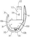
도 1은 본 발명의 실시 형태에 따르는 완전히 굽은 무릎 보철물의 사시도.
도 2는 도 1에 도시된 대퇴골 구성요소의 근위 장착 표면을 도시하는 사시도.
도 3은 도 1에 도시된 대퇴골 구성요소의 근위 장착 표면을 도시하는 또 다른 사시도.
도 4는 도 1에 도시된 대퇴골 구성요소의 상부 (근위) 평면도.
도 5는 도 1에 도시된 대퇴골 구성요소의 뒤쪽 입면도.
도 6은 도 1에 도시된 대퇴골 구성요소의 앞쪽 입면도.
도 7은 도 1에 도시된 대퇴골 구성요소의 횡방향 입면도.
도 8은 도 1에 도시된 대퇴골 구성요소의 중앙 입면도.
도 9는 도 5의 선 9-9를 따라 취한 단면도.
도 11 및 도 12는 도 1에 도시된 경골 라이너의 각각의 앞쪽 및 뒤쪽 사시도.
도 13은 도 1에 도시된 경골 라이너의 중앙 입면도.
도 14는 도 1에 도시된 경골 라이너의 앞쪽 입면도.
도 15는 도 1에 도시된 경골 라이너의 상부 (근위) 평면도.
도 16은 도 15의 선 16-16을 따라 취한 단면도.
도 17은 도 15의 선 17-17을 따라 취한 단면도.
도 18a 내지 도 20c는 대퇴골 구성요소의 점진적으로 감소하는 중앙-횡방향(가로방향 면)의 도면.
도 21a 내지 도 23c는 대퇴골 구성요소가 완전히 펼쳐진 위치로부터 중간 위치로 그 뒤에 완전히 굽은 위치로 회전함에 따라 대퇴골 구성요소의 점진적으로 감소하는 내반-외반(관상면) 회전 이완성을 도시하는 도면.
도 24는 본 발명의 또 다른 실시 형태에 따르는 가이드 박스 슬롯의 도면.
도 25는 본 발명의 추가 실시 형태에 따르는 가이드 박스 슬롯의 도면.
도 26은 본 발명의 추가 실시 형태에 따르는 가이드 박스 슬롯의 도면.1 is a perspective view of a fully bent knee prosthesis in accordance with an embodiment of the present invention.
FIG. 2 is a perspective view showing the proximal mounting surface of the femur component shown in FIG. 1. FIG.
FIG. 3 is another perspective view showing the proximal mounting surface of the femur component shown in FIG. 1. FIG.
4 is a top (proximal) top view of the femur component shown in FIG. 1;
5 is a rear elevational view of the femur component shown in FIG.
FIG. 6 is a front elevation view of the femur component shown in FIG. 1. FIG.
FIG. 7 is a transverse elevation view of the femur component shown in FIG. 1. FIG.
8 is a central elevation view of the femur component shown in FIG.
9 is a sectional view taken along line 9-9 of FIG.
11 and 12 are front and rear perspective views, respectively, of the tibial liner shown in FIG. 1.
FIG. 13 is a central elevation view of the tibial liner shown in FIG. 1. FIG.
14 is a front elevation view of the tibial liner shown in FIG. 1.
15 is a top (proximal) top view of the tibial liner shown in FIG. 1.
FIG. 16 is a cross sectional view taken along line 16-16 of FIG. 15;
FIG. 17 is a cross sectional view taken along line 17-17 of FIG. 15;
18A-20C are views of the progressively decreasing mid-lateral direction (horizontal face) of the femur component.
21A-23C show the progressively decreasing varus-vemoral (tubular) rotational relaxation of the femur component as the femur component rotates from the fully deployed position to the intermediate position and then fully bent.
24 is a view of a guide box slot according to another embodiment of the present invention.
25 is a view of a guide box slot in accordance with a further embodiment of the present invention.
26 is a view of a guide box slot according to a further embodiment of the present invention.
본 발명을 예시하기 위하여, 첨부된 도면에 본 발명의 몇몇 실시 형태들이 도시된다. 그러나, 당업자는 본 발명이 도면에 도시되고 하기에서 기술된 정확한 장치들과 기기들에 제한되는 것이 아니라는 것을 이해해야 한다. 본 명세서 전반에 걸쳐, 유사한 도면부호들은 유사한 요소들을 가리키는 것으로 사용된다. 상세한 설명을 통해 해당 업계의 당업자들에게는 본 발명의 사상과 범위 내에서 여러 변형예들과 변경예들이 가능하다는 것이 명백할 것이다.To illustrate the invention, there are shown some embodiments of the invention in the accompanying drawings. However, those skilled in the art should understand that the present invention is not limited to the precise devices and devices shown in the drawings and described below. Throughout this specification, like reference numerals are used to indicate like elements. Detailed description will be apparent to those skilled in the art that various modifications and variations are possible within the spirit and scope of the invention.
그 외에 달리 정의되지 않는다면, 본 명세서에 사용된 모든 기술적 및 과학적 용어들과 이들의 여러 문법적 형태들은 본 발명이 속하는 해당 업계의 당업자에게 공통적으로 이해되는 동일한 의미를 가진다. 본 명세서에서 용어 내반(varus), 외반(valgus), 앞쪽, 뒤쪽, 근위, 원위, 중앙, 횡방향, 시상(sagittal), 관상(coronal), 및 가로방향은 예를 들어 Dorland사의 Illustrated Medical Dictionary에서 정의된 바와 같은 통상적인 의학/해부학 의미들로 사용된다. 용어 이완성(laxity)은 무릎 관절의 회전 운동의 느슨함 또는 변위를 의미한다. 용어 구속성(restraint)은 무릎 관절의 회전 운동의 제한 또는 한정을 의미한다. 외반-내반 구속성은 관상 면(coronal plane)에서의 회전 또는 틸팅 제한 또는 한정을 의미한다. 중앙-횡방향 구속성은 가로방향 평면에서 회전의 제한 또는 한정을 의미한다. 용어 "구속성 δR의 변화"는 시상면에서 의족의 회전 각도 또는 외반-내반 구속성 또는 중앙-횡방향 구속성의 증가 또는 감소를 의미한다. 구성요소들이 회전하기 때문에, 다양한 특징부들의 배향이 도 1에 도시된 바와 같이 완전한 굴곡의 구성에 대해 기재된다.Unless defined otherwise, all technical and scientific terms used herein and their various grammatical forms have the same meanings as commonly understood by one of ordinary skill in the art to which this invention belongs. As used herein, the terms varus, valgus, anterior, posterior, proximal, distal, central, transverse, sagittal, coronal, and transverse are described, for example, in the Illustrated Medical Dictionary of Dorland. Used in conventional medical / anatomical meanings as defined. The term laxity means looseness or displacement of the rotational movement of the knee joint. The term restraint means limiting or limiting the rotational movement of the knee joint. Valgus- varus constraint means rotational or tilting limitations or limitations in the coronal plane. Center-lateral restraint means a limitation or limitation of rotation in the transverse plane. The term "change of binding δR" means an increase or decrease in the rotational angle or varus-valgus restraint or center-lateral restraint of the limb in the sagittal plane. As the components rotate, the orientation of the various features is described for the configuration of complete bend as shown in FIG. 1.
본 발명의 제1 선호되는 실시 형태에 따른 무릎 교정 보철물(revision knee prosthesis)이 도 1-23에 예시되며 일반적으로 도면부호(10)로 표시된다. 이 보철물(10)은 절제된 대퇴부(femur)의 원위 단부에 고정될 수 있도록 설계되고 구성된 대퇴부 구성요소(femoral component, 20) 및 절제된 경골(tibia)의 근위 단부에 고정될 수 있도록 설계되고 구성된 경골 구성요소(tibial component, 52)를 포함한다. 이 구성요소(20, 52)들은, 각각, 통상적인 방법들을 사용하여 종래의 대퇴부 및 경골 절제 후에 대퇴부 및 경골에 고정될 수 있다. 경골 구성요소(52)는 좌측 무릎 또는 우측 무릎 중 어느 쪽에도 사용될 수 있는 대칭적인 설계를 갖지만, 대퇴부 구성요소는 비대칭이며 도 1-23에서는 좌측 무릎용이 예시된다. 우측 무릎에 설치하기 위해 대퇴부 구성요소(20)의 거울상이 사용될 것이다.Revision knee prosthesis according to a first preferred embodiment of the present invention is illustrated in FIGS. 1-23 and generally indicated by
대퇴부 구성요소(20)는 중앙 관절구 부분 또는 과상돌기(22), 횡방향 관절구 부분 또는 과상돌기(24), 및 슬개골 플랜지 부분 또는 플랜지(26)를 가지는데, 이들은 각각 중앙 과상돌기(22)와 횡방향 과상돌기(24)의 앞쪽 단부(28, 30)에 걸쳐지고, 각각 상기 중앙 과상돌기(22)와 횡방향 과상돌기(24)의 뒤쪽 단부(29, 31)에 걸쳐있고 이를 연결하는 캠(47)을 포함한다. 중앙 과상돌기(22)와 횡방향 과상돌기(24)는 서로 실질적으로 평행하게 배열되며 이들 사이에서 슬관절(intercondylar) 노치(32)를 형성한다. 보철물이 굽어지기 때문에, 만곡된 관절구 부분들의 서로 다른 단면들이 경골 구성요소(52)와 맞물리고 관절연결된다.The
슬개골 플랜지(26)는 중앙 활차 표면(medial trochlear surface, 44)과 횡방향 활차 표면(46)에 의해 측면을 접하는 슬개골 홈(42)을 포함한다. 슬개골 플랜지는 선천적 슬개골 또는 슬개골 구성요소와 관절연결되도록 설계된다. 슬개골 플랜지는 과상돌기(22, 24)와 부드럽게 변이된다. 슬개골 플랜지는 선천적 대퇴부의 앞쪽 원위 표면의 기하학적 형상에 가깝게 구성된다. 그 결과, 슬개골 플랜지는 보철 또는 선천적 슬개골의 선천적인 궤도를 가진다.The
각각의 과상돌기(22, 24)는 일반적으로 앞쪽 표면(34, 48)과 뒤쪽 표면(36, 40)을 포함하는데, 이들은 급격하게 변이되지 않고도 서로 부드럽게 뒤섞인다(blend). 도 1-23에 도시된 선호되는 실시 형태에서, 앞쪽 표면과 뒤쪽 표면들은 경골 섹션과 서로 비슷하며, 이들 각각의 표면은 시상면에서 실질적으로 주축(major axis)에 대한 반경(주 반경)을 가진다. 보통, 과상돌기(22, 24)의 곡률의 주 반경은 높은 각도로 굽혀지는 동안 해부학적 대퇴부 롤백(rollback)을 따라가도록 전방으로부터 후방으로 변한다. 예를 들어, 앞쪽 표면(34)의 주 반경은 뒤쪽 표면(38)의 주 반경보다 더 큰 것이 바람직하다. 또한 앞쪽 표면과 뒤쪽 표면의 주 반경은 나중 절차(proceeding)를 줄일 수 있다. 예를 들어 도 1-23에 도시된 실시 형태에서, 뒤쪽 표면(36, 40)이 추후에 주 반경 절차를 급히 줄일 때 앞쪽 표면(34, 38)은 주 반경을 서서히 줄인다. 과상돌기(22, 24)의 뒤쪽 단부(29, 31)를 가까이 하여, 주 반경은 보철물이 바람직하게는 100°이상, 더 바람직하게는 130°이상 굽혀지게 하도록 매우 감소되는 것이 바람직하다. 게다가, 단부(29, 31)의 작은 반경은 경골 라이너(60) 상에서 구성요소들 간의 접촉상태를 유지하면서 과상돌기(29, 31)의 에지 로딩(edge loading)을 방지한다.Each
과상돌기(22, 24)는 관상면(coronal plane)에서 부축(minor axis)에 대한 반경을 가진다. 선호되는 일 실시 형태에서, 과상돌기는 관상면에서 일정한 곡률 반경을 가진다. 그러나, 과상돌기 표면들은 더욱 복잡한 기하학적 형상을 가질 수 있으며, 관상면의 곡률 반경이 변화할 수 있다. 특히, 뒤쪽 과상돌기 표면들이 세 평면 모두에서 가변 반경으로 설계될 수 있다.The
중앙 및 횡방향 과상돌기(22, 24)의 내부 경계는 이들 사이에 슬관절 노치(32)를 형성한다. 가이드 박스(100)는 슬관절 노치(32)에 걸쳐 있고 대퇴부 구성요소(20)의 근위 장착 표면(21)에 대해 중심에 고정된다. 가이드 박스(100)는 각각의 과상돌기(22, 24)의 내부 에지를 따라 일반적으로 평행한 시상면 내에서 근위방향으로 연장되는 중앙 및 횡방향 웨브(102, 104)로부터 형성된다. 도 7 및 도 8을 참조하면, 각각의 웨브(102, 104)는 각각 각각의 과상돌기 부분(22, 24)의 내부 에지에서 불규칙적으로 형성된 근위 장착 표면(21)과 일체로 형성되는 불규칙적으로 형성된 하부 에지(102b, 104b) 및 직선형 상부 에지(102a, 104a)를 갖는다. 웨브의 높이가 보철물의 크기에 따라 변화할지라도, 웨브의 높이는 후술된 바와 같이 중앙 포스트(90)와 결합 시에 원하는 구속성을 제공하기에 충분히 커야 한다. 도 1 내지 도 22에 도시된 실시 형태에서, 웨브는 대략 13 mm 내지 20 mm의 높이이다. 도 4에 가장 잘 도시된 바와 같이, 브리지 플레이트(106)는 웨브(102, 104)의 상부 에지(102a, 104a)에 연결된다. 브리지 플레이트(106)는 각각의 웨브(102, 104)의 상부 에지에서 중간 지점(108)으로 앞쪽 장착 표면으로부터 가로방향 평면 내에서 연장된다. 뒤쪽 에지(106d), 캠(47), 및 웨브(102, 104)의 상부 에지(102a, 104a)는 중앙 포스트(90)가 후술된 바와 같이 병진운동 및 회전하는 박스 가이드 슬롯(110)을 형성한다. The inner boundaries of the central and transverse
도 4, 도 9 및 도 10을 참조하면, 가이드 박스 슬롯(110)은 일반적으로 사다리꼴 형상을 갖는다. 도 10의 확대도에서 가장 잘 도시된 바와 같이, 슬롯(110)은 "AW"보다 넓은 뒤쪽 단부 폭 "PB" 및 앞쪽 단부 폭 "AW"을 갖는다. 도 10에 도시될지라도, "AW"와 "PW"의 차이는 바람직하게는 대략 1 mm이지만 보철물의 원하는 성능 특성에 따라 더 크거나 또는 더 작을 수 있다. 선호되는 실시 형태에서, 중앙 및 횡방향 웨브(102, 104)는 뒤쪽으로 진행함에 따라 감소되는 두께를 갖는다. 이 실시 형태에서, 웨브의 외부 표면(102d, 104d)은 서로 평행할지라도 내부 표면(102c, 104c)은 서로 비스듬하여 사다리꼴 내부 가이드 슬롯을 형성한다. 도 24에 도시된 또 다른 실시 형태에서, 유사한 기능이 균일한 두께를 갖는 웨브 벽(202, 204)에 따라 구현될 수 있다. 그러나, 이 실시 형태에서, 내부 벽(202c, 204c)과 외부 벽(202d, 204d)은 서로 비스듬하다.4, 9, and 10, the
도 5와 도 14에서 잘 볼 수 있듯이, 캠(47)이 중앙 과상돌기(22)와 횡방향 과상돌기(24)의 뒤쪽 단부(29, 31)에 걸쳐지고 연결된다. 도 16에서, 상기 캠(47)은 일반적으로 평평한 후방 표면(48)과 만곡된 전방 지지 표면(49)을 가진다. 후방 표면(48)은 과상돌기(22, 24)의 후방(근위) 표면과 공면으로 배향되며 원위 대퇴부의 절제된 표면에 대해 평평하다. 도 5에서 잘 볼 수 있듯이, 지지 표면(49)의 곡률 반경은 중앙 단부(50)보다 횡방향 단부(51)에서 더 크다. 하기에서 자세히 기술되는 것처럼, 캠(47)은 무릎이 굽혀질 때 안정성과 경골 회전력을 제공하기 위해 경골 지지 라이너(60) 상에서 중앙 포스트(90)와 맞물린다.As can be seen in FIGS. 5 and 14, the
보스(boss, 112)는 브리지 플레이트(106)의 근위 표면에 고정된다. 보스(112)는 일반적으로 원통형 형상을 가지며, 도 1에 도시된 골수강내 장착 스템(intermedullary mounting stem, 9)을 수용하도록 크기가 형성되어 공지된 수술 교정 기법을 이용하여 대퇴골 구성요소에 대한 고정을 돕는다. 반경방향 보어(114)는 보스(112)의 벽을 통하여 연장된다. 도 5에 가장 잘 도시된 바와 같이, 보스는 브리지 플레이트(106)에 대해 작은 각도로 연장된다. 각도는 지면에 대한 대퇴골 골수강내 강의 각도와 유사하다. 스템이 보스(112) 내에 삽입되면, 세트 스크류 또는 핀이 보어(114)를 통하여 스템 내로 삽입되어 스템이 보어(114) 내에 고정된다. 보스(112)는 또한 대퇴골 스템(8) 상에 대퇴골 구성요소(20)를 적절히 배향하기 위하여 복수의 정렬 표시자(122)를 포함한다.
도 3 및 도 4를 참조하면, 근위 장착 표면(21)은 과상돌기 부분(29, 31)의 뒤쪽 단부로 슬개골 플랜지 부분(26)으로부터 이어지는 개별 표면 부분(21a-e)을 포함한다. 개별 장착 표면은 절제된 대퇴골 상에서 상보적 표면과 결합되고 시멘트(cement)를 이용하여 이에 고정된다. 중간 장착 표면(21c)과 뒤쪽 장착 표면(21e)은 원하는 경우 오그멘트(augment)(도시되지 않음)를 부착하기 위해 사용되는 나사산 체결구와 각각 결합되는 나사산 보어(118, 120)를 포함한다. 중간 장착 표면(21c)은 또한 사이징 및/또는 교체 동안에 대퇴골 구성요소의 제거를 돕는 중앙 및 횡방향 노치(116)를 포함한다. 노치(116)는 절제된 대퇴골에 정확한 크기의 구성요소가 영구적으로 부착되면 시멘트 포켓으로서 기능을 한다.With reference to FIGS. 3 and 4, the proximal mounting
도 1을 참조하면, 경골 구성요소(52)는 일반적으로 경골 플랫폼(54)과 라이너(60)를 포함한다. 경골 플랫폼(54)은 기저 플레이트(55)를 가지는데, 이 기저 플레이트(55)는 경골의 골수 캐널(medullary canal) 내에 삽입된 안정 용골(56)과 라이너(60)의 원위 표면(64)과 맞물린다. 기저 플레이트(55)의 하측면 또는 원위 표면은 텍스쳐링되고(textured) 거칠게 된(roughened) 표면을 가지며 이 표면은 경골 상에 장착하는 동안 깍지끼우듯이 접합되게 할 수 있다.Referring to FIG. 1, the
라이너(60)는 대퇴부 구성요소(20)와 관절연결식 근위 지지 표면(62)과 경골 플랫폼(52)에 고정되고 이 경골 플랫폼(52)과 접하고 있는 원위 표면(64)을 가진다. 또한 경골 구성요소(50)는 중앙 측면(66), 횡방향 측면(68), 앞쪽 측면(70) 및 뒤쪽 측면(71)을 가진다. 경골 구성요소는 일반적으로 앞쪽으로부터 뒤쪽으로 형성되는 중앙 시상면에 대해 대칭이다.The
중앙 오목부(72)와 횡방향 오목부(74)는 각각 근위 표면(62)의 중앙 측면과 근위 측면에 형성된다. 중앙 오목부(72)와 횡방향 오목부(74)는 이 구성요소들이 서로에 대해 관절연결되기 때문에 대퇴부 구성요소(20)의 중앙 과상돌기(22)와 횡방향 과상돌기(24)와 맞물린다. 일반적으로, 상기 오목부(72, 74)들은 대퇴부 과상돌기(22, 24)의 깊이보다 더 얕다.The
각각의 오목부(72, 74)는 일반적으로 앞쪽 표면(76, 78)과 뒤쪽 표면(80, 82)을 포함하며, 이들은 각각 토로이달 단면과 유사하고 중간의 경계면에서 서로 뒤섞인다. 선호되는 실시 형태에서, 앞쪽 표면(76, 78)은 실질적으로 시상면에 배향된 주 곡률 반경을 가진다. 바람직하게는, 뒤쪽 표면(80, 82)들은 실질적으로 횡단 평면에 배향된 주 곡률 반경을 가진다. 뒤쪽 오목부(80, 82)는 중앙 시상면을 향하여 그리고 후방으로 이어지고, 시상면 중앙 축을 향하여 내부방향으로 굽어진다. 앞쪽 표면(76, 78)과 뒤쪽 표면(80, 82)은 관상면에서 동일하고 일정한 곡률 반경을 가지며 관상면에서 동일한 접선방향 교차면을 공유한다. 뒤쪽 표면의 관상 곡률(coronal curvature)은 뒤쪽 표면이 중앙의 시상축을 향해 회전할 때 유지된다. 이러한 구성은 경골이 경골의 종축 주위로 회전할 수 있게 하고 무릎이 굽혀질 때 후방으로 병진운동할 수 있게 한다.Each
앞쪽 오목부와 뒤쪽 오목부들은 경골로부터 대퇴부를 포함하고 대퇴부가 탈구되는 것을 방지하기 위해 앞쪽 단부(86)와 뒤쪽 단부(88)에서 올라간 주연부(periphery)를 가진다. 굽혀지는 동안 상기 올라간 주연부도 무릎에 안정성을 제공한다. 앞쪽 오목부들은 횡방향 경사부(elevation, 89)를 가지는데, 이 횡방향 경사부(89)는 과상돌기(22, 24)를 가지며 이에 따라 경골 구성요소들은 초기에 굽혀지는 동안 거의 이완되지 않고 경골이 축방향으로 회전되는 것을 방지한다. 이에 반해, 뒤쪽 오목부들은 횡방향 경사부를 포함하지 않도록 설계되고 경골이 축방향으로 회전할 수 있게 설계된다.The anterior and posterior recesses include the femur from the tibia and have periphery raised from the
도 1-23에 도시된 실시 형태에서, 경골 구성요소(60)는 근위 표면(91), 앞쪽 표면(92), 뒤쪽 표면(93), 중앙 측면 표면(94) 및 횡방향 측면 표면(95)을 가진 중앙 포스트(90)를 포함한다. 중앙 포스트(90)의 앞쪽 표면(92)은 깊이 굽혀져 슬개골 또는 슬개골 임플란트가 부딪치는 것을 최소화하기 위해 원위 표면(64)에 대해 일정각도로 테이퍼구성된다. 도 14에 가장 잘 도시된 바와 같이, 포스트(90)의 중앙 측면(94)과 횡방향 측면(95)은 평행하고 일정한 중앙-횡방향 폭 "MLW"을 갖는다. 선호되는 실시 형태에서, 중앙-횡방향 폭은 박스 가이드 슬롯의 앞쪽 폭 "AW"보다 약간 좁다. 이의 구속 능력을 최대화하기 위하여, 포스트(90)의 높이는 유사해야 하지만 웨브(102, 104)의 높이보다 약간 작고, 포스트(90)는 무릎이 거의 완전히 펼쳐진 상태로 놓여질 때 브리지 플레이트(106)와 간섭될 것이다.In the embodiment shown in FIGS. 1-23, the
대퇴부 및 경골 구성요소의 상대 운동 경로가 도 18 내지 도 23에 도시된다. 자연적인 무릎과 같이, 과상돌기(22, 24)의 앞쪽 표면(34, 38)은 완전히 펼쳐진 범위에서(도 18 및 도 21) 경골 구성요소를 부분적으로 구부린 중간 위치(도 19 및 도 22)로 접촉시키고 그 후에 완전히 구부린 위치(도 20 및 도 23)에 접촉시킨다. 대퇴부 구성요소가 회전함에 따라, 중앙 포스트(90)는 박스 가이드 슬롯(110) 내에서 병진운동한다. The relative paths of motion of the femoral and tibial components are shown in FIGS. 18-23. As with the natural knee, the
완전히 펼쳐졌을 때, 중앙 포스트(90)는 도 18b에 가장 잘 도시된 바와 같이 가이드 슬롯의 앞쪽 단부 부분에 배치된다. 이 위치에서, 보철물은 최대 중앙-횡방향 구속성 및 외반-내반 구속성을 가지며 이는 중앙 포스트(90)의 중앙-횡방향 폭 "CW"이 가이드 슬롯(110)의 앞쪽 내부 폭 "AW"보다 단지 약간 좁기 때문이다. 선호되는 실시 형태에서, "AW"에서 "CW"를 뺀 차이는 대략 0.1 mm 내지 0.25 mm이다. 따라서, 대퇴부 구성요소는 도 18c에서 알파 1(α1)로 나타내진 매우 작은 가로방향 회전 이완성을 갖는다. 선호되는 실시 형태에서, 알파(α1)는 대략 1°이다. 대퇴부 구성요소는 또한 도 21c에서 베타 1(β1)로 나타내진 매우 작은 중앙-횡방향 회전 이완성을 갖는다. 선호되는 실시 형태에서, 베타(1)(β1)는 대략 2°이다. When fully deployed, the
대퇴부 구성요소가 도 19a 및 도 22a에 도시된 중간 위치로 회전함에 따라, 중앙 포스트(90)는 도 18b에 가장 잘 도시된 바와 같이 가이드 슬롯의 앞쪽 및 뒤쪽 단부 부분을 배치하기 위하여 가이드 슬롯(110) 내에서 이동한다. 이 중간 위치에서, 보철물은 완전히 펼쳐진 것에 비해 감소된 중앙-횡방향 구속성 및 감소된 외반-내반 구속성을 가지며 이는 중앙 및 횡방향 웨브(102, 104)의 내부 표면(102c, 104c)과 중앙 포스트(90)의 측면 사이의 간격이 증가되기 때문이다. 간격은 증가하는데, 이는 슬롯(110)의 내부 폭이 앞쪽 폭(AW)보다 가이드 슬롯의 중간 영역에서 더 넓기 때문이며, 반면 중앙 포스트(90)의 중앙 횡방향 폭 "CW"은 일정하다. 따라서, 대퇴부 구성요소는 도 19c에 도시된 바와 같이 α1에 비해 증가된 가로방향 회전 이완성 알파 2(α2)를 갖는다. 대퇴부 구성요소는 또한 도 22c에 도시된 바와 같이 β2에 비해 증가된 중앙-횡방향 회전 이완성 베타 2(β2)를 갖는다. As the femoral component rotates to the intermediate position shown in FIGS. 19A and 22A, the
대퇴부 구성요소가 도 20 및 도 23에 도시된 완전히 펼쳐진 위치로 회전함에 따라, 비대칭 캠(47)은 경골 포스트(90)와 관절연결되고, 이에 따라 대퇴부 구성요소는 도 20 및 도 23에 가장 잘 도시된 바와 같이 경골 구성요소(52)에서 후방으로 병진운동한다. 선호되는 실시 형태에서, 대퇴부 구성요소의 후방을 향하는 병진운동은 대략 1 내지 2 밀리미터로 제한된다. 완전히 구부려졌을 때, 중앙 포스트(90)는 도 20b에 가장 잘 도시된 바와 같이 가이드 슬롯의 뒤쪽 단부 부분에 배치된다. 이 위치에서, 보철물은 최소 중앙-횡방향 구속성 및 최소 외반-내반 구속성을 가지며, 이는 중앙 및 횡방향 웨브(102, 104)의 내부 표면(102c, 104c)과 중앙 포스트(90)의 측면 사이의 간격이 중간 위치에 비해 심지어 더 크게 증가하기 때문이다. 간격은 증가하는데, 이는 뒤쪽 단부에서의 가이드 슬롯의 내부 폭 "PW"이 최대이기 때문이며, 반면 중앙 포스트(90)의 중앙-횡방향 폭 "CW"은 일정하다. 선호되는 실시 형태에서, "PC"에서 "CW"을 뺀 차이는 대략 0.5 내지 1 mm이다. 따라서, 대퇴부 구성요소는 도 20c에 도시된 바와 같이 α2에 비해 증가된 가로방향 회전 이완성 알파 3(α3)을 갖는다. 선호되는 실시 형태에서, α3은 대략 4° 미만이다. 대퇴부 구성요소는 또한 도 23c에 도시된 바와 같이 β2에 비해 증가된 중앙-횡방향 회전 이완성 베타 3(β3)을 갖는다. 선호되는 실시 형태에서, β3은 대략 7° 미만이다.As the femoral component rotates to the fully extended position shown in FIGS. 20 and 23, the
유사한 방식으로, 대퇴부 구성요소가 완전히 구부러진 위치 또는 중간 구부러진 위치로부터 재차 완전히 펼친 위치로 회전함에 따라, 중앙-횡방향 구속성 및 외반-내반 구속성은 점차 증가한다. 대퇴부 구성요소가 완전히 펼쳐진 위치로 복귀됨에 따라 가이드 슬롯(110)과 중앙 포스트(90) 사이의 간격은 최소로 감소되고 이에 따라 무릎이 추가로 구속된다.In a similar manner, as the femoral component rotates from the fully bent position or the intermediate bent position back to the fully extended position, the mid-lateral restraint and varus-valgus restraint gradually increase. As the femoral component is returned to the fully extended position, the spacing between the
전술된 바와 같이, 보철물의 고유 설계에 따라 완전히 펼쳐졌을 때 원하는 최대 중앙-횡방향 구속성 및 외반-내반 구속성이 가능하다. 고유 설계에 따라 또한 무릎이 구부러짐에 따라 점진적으로 감소 및 증가하는 구속성이 제공된다. 고유 설계로 인해, 지지 표면의 기하학적 형상 및 캠(47)의 만곡된 지지 표면(49)은 무릎이 구부러짐에 따라 경골이 축방향으로 회전한다. 선호되는 실시 형태에서, 경골 회전은 최대 약 5°, 바람직하게는 최대 적어도 약 6°, 더욱 바람직하게는 최대 약 7°까지 가능하다. 그러나, 캠 및 관절연결 표면은 원하는 경우 더 큰 경골 축방향 회전이 가능하도록 설계될 수 있다.As mentioned above, the maximum central-lateral restraint and valgus-valgus restraint desired when fully deployed in accordance with the inherent design of the prosthesis is possible. The unique design also provides restraint that gradually decreases and increases as the knee is bent. Due to the unique design, the geometry of the support surface and the
보철물(10)이 다양한 크기의 환자에게 적용되도록 다양한 크기로 제공될 수 있는 것은 당업자에게 자명하다. 따라서, 특정 구성요소에 대해 전술된 치수는 명확히 변화할 것이다. It will be apparent to those skilled in the art that the
게다가, 보철물은 본 발명의 범위로부터 벗어나지 않고 다양한 성능 특성으로 제공될 수 있다. 예를 들어, 보철물(10)은 작은 δR 또는 큰 δR 및 완전히 구부려졌을 때 높은 구속성을 갖도록 맞춤 설계될 수 있다. 유사하게, 보철물(10)은 작은 δR 또는 큰 δR 및 완전히 구부려졌을 때 더 작은 구속성을 갖도록 맞춤 설계될 수 있다. 각각의 경우에, 높은 수준의 구속성은 보철물(10)의 구부러짐 범위에 걸쳐 변화할 수 있다. 각각의 경우, 그러나 구속성의 상대적인 수준은 보철물(10)의 굽힘 범위에 따라 변화할 것이다. In addition, the prosthesis can be provided with a variety of performance characteristics without departing from the scope of the present invention. For example, the
도 10 및 도 24에 도시된 실시 형태에서, 가이드의 내부 표면의 평면형 프로파일은 회전함에 따라 대퇴부 구성요소 상에서 구속성(δR)에서 일정한 변화(델타)를 생성하고, 본 발명의 추가 실시 형태에서 중앙 및 횡방향 웨브의 내부 표면은 다양한 δR 프로파일을 생성하는 비-평면형 또는 불규칙적인 형상을 가질 수 있다. 예를 들어, 도 25에 도시된 만곡된 내부 표면 프로파일은 완전한 굽힘 범위에 걸쳐 변수(δR)를 생성한다.10 and 24, the planar profile of the inner surface of the guide produces a constant change (delta) in restraint (δR) on the femoral component as it rotates, and in a further embodiment of the invention the central and The inner surface of the transverse web may have a non-planar or irregular shape that produces various δR profiles. For example, the curved inner surface profile shown in FIG. 25 produces the variable δR over the complete bending range.
게다가, 심지어 더욱 복합적인 δR 프로파일을 생성하기 위하여, 중앙 및 횡방향 웨브의 내부 표면은 도 26에 도시된 바와 같이 개별 캠 표면(405, 406)과 끼워맞춤될 수 있다. 캠의 외부 표면(405d, 406d)은 중앙 및 횡방향 웨브의 내부 표면(402c, 404c)과 접한다. 도 26에 도시된 실시 형태에서, 캠의 내부 표면(405c, 406c)은 슬롯의 제1 영역(410a)에서 0(δR)을 생성하고 슬롯의 제2 영역(410b)에서 변수(δR)를 생성한다. 영역(410a, 410b)은 정해진 범위의 굴곡에 대응한다. 예를 들어, 제1 영역(410a)은 0° 내지 X°의 굴곡 범위, 즉 소정의 중간 각 위치(X)에 대한 완전 펼침에 대응된다. 제1 굴곡 범위 내에서, 보철물은 일정하고 미리 정해진 수준의 구속성을 갖는다. 제2 영역(410b)은 X° 내지 Y°의 굴곡 범위, 즉 최대 각 위치(Y)에 대한 중간 위치에 대응한다. 제2 굴곡 범위 내에서, 구속성의 수준은 무릎이 주기적으로 X°로부터 Y°로 그 후에 재차 X°로 구부러짐에 따라 비-연속 속도에서 감소 및 증가한다. X 및 Y의 값은 본 발명의 범위로부터 벗어나지 않고 변화할 수 있다.In addition, to create even more complex δR profiles, the inner surfaces of the central and transverse webs can be fitted with individual cam surfaces 405 and 406 as shown in FIG. The
심지어 더욱 복합적인 캠이 중앙 및 횡방향 웨브의 내부 표면에 끼워맞춤될 수 있으며, 이에 따라 다수의 개별 굴곡 범위에 걸쳐서 다수의 개별 δR 프로파일이 생성될 수 있다. 많은 다른 유용한 표면 프로파일이 당업자에게 자명하다.Even more complex cams can be fitted to the inner surfaces of the central and transverse webs, resulting in multiple individual δR profiles over multiple individual bend ranges. Many other useful surface profiles are apparent to those skilled in the art.
대퇴골 구성요소 및 경골 구성요소는 다양한 표면 프로파일을 가질 수 있고, 2009년 2월 18일자의 "Total Knee Replacement Prosthesis with High order NURBS Surfaces"라는 명칭의 미국 특허 출원 제12/388,125호 및 2009년 2월 18일자의 "Total Knee Replacement Prosthesis"라는 명칭의 미국 특허 출원 제12/388,182호에 기재된 것과 같이 다양한 방식 및 다양한 재료로 구성될 수 있고, 상기 문헌들은 본 명세서에 참조로 인용된다. 예를 들어, 대퇴골 구성요소(20)와 경골 플랫폼(54)은 예컨대, 코발트 크롬 합금, 스테인리스 스틸, 티타늄, 티타늄 합금 또는 니켈 코발트 합금과 같은 의료용의 생리학적으로 허용가능한 금속으로부터 단일의 일체 유닛으로서 기계가공, 주조, 단조 또는 이와는 달리 구성될 수 있다.The femur component and the tibial component can have various surface profiles and are described in US Patent Application Nos. 12 / 388,125 and February 2009, entitled “Total Knee Replacement Prosthesis with High order NURBS Surfaces”, dated February 18, 2009. It may be configured in a variety of ways and in various materials, such as described in US Patent Application No. 12 / 388,182, entitled "Total Knee Replacement Prosthesis" dated 18, which is incorporated herein by reference. For example,
또한 경골 라이너도 다양한 방법들과 다양한 재료들로 제조될 수 있다. 예를 들어, 경골 라이너는 기계가공될 수 있고, 몰딩가공될 수 있거나 또는 그 외의 경우 고밀도 폴리에틸렌, 저밀도 폴리에틸렌, 선형-저밀도 폴리에틸렌, 초고분자량 폴리에틸렌(UHMWPE), 또는 이들의 혼합물들을 포함하는, 임의의 폴리올레핀과 같은 의료용, 생리학적으로 허용가능한 폴리머 재료들로부터 단일의 일체형 유닛으로서 제조될 수 있다. 또한 본 명세서에서 사용되는 폴리머 재료들은 다양한 형태, 예를 들어, 수지 분말, 플레이크, 입자, 분말, 또는 이들의 혼합물 또는 위의 어느 것으로부터도 나온 경화 형태의 폴리에틸렌을 포함한다. 초고분자량 폴리에틸렌(UHMWPE)은 대략 500,000을 초과하는, 바람직하게는 대략 1,000,000을 초과하는, 보다 바람직하게는 대략 2,000,000을 초과하는 초기 평균 분자량을 가진 선형, 비-분지 사슬(non-branched chain) 에틸렌을 의미한다. 종종 분자량은 대략 8,000,000 또는 그 이상까지도 도달할 수 있다. 상기 재료는 재료의 마모 특성 및/또는 강도 또는 경도를 변경하기 위해 예를 들어 방사선, 화학, 또는 그 외의 기술로 가공처리될 수 있다. 초기 평균 분자량은 방사선 가공 전에 UHMWPE 시작 재료의 평균 분자량을 의미한다.Tibial liners can also be made in a variety of methods and in various materials. For example, the tibial liner can be machined, molded or otherwise, including any of high density polyethylene, low density polyethylene, linear-low density polyethylene, ultra high molecular weight polyethylene (UHMWPE), or mixtures thereof. It may be prepared as a single unitary unit from medical, physiologically acceptable polymeric materials such as polyolefins. Polymeric materials as used herein also include polyethylene in various forms, such as resin powders, flakes, particles, powders, or mixtures thereof or in cured form from any of the above. Ultra High Molecular Weight Polyethylene (UHMWPE) comprises a linear, non-branched chain ethylene having an initial average molecular weight of greater than approximately 500,000, preferably greater than approximately 1,000,000, more preferably greater than approximately 2,000,000. it means. Often the molecular weight can reach up to approximately 8,000,000 or more. The material can be processed, for example, by radiation, chemistry, or other techniques to alter the wear properties and / or strength or hardness of the material. Initial mean molecular weight refers to the average molecular weight of the UHMWPE starting material prior to radiation processing.
대표 실시 형태들을 기술하면서, 상세한 설명, 특정 예들과 데이터는 오직 예시 목적으로 주어지는 것이며 본 발명을 제한하기 위함이 아니라는 것을 이해할 수 있다. 해당 업계의 당업자들에게 본 발명 범위 내에서 본 명세서에 포함된 논의사항, 설명 및 데이터들로부터 다양한 변경예들과 변형예들이 가능하며 이것들이 본 발명의 일부로 간주되는 것은 명백할 것이다.While describing representative embodiments, it is to be understood that the detailed description, specific examples and data are given for illustrative purposes only and are not intended to limit the invention. It will be apparent to those skilled in the art that various modifications and variations are possible within the scope of the present invention and from the discussion, description and data contained herein and that they are considered part of the present invention.
Claims (23)
a) 절제된 대퇴부의 원위 단부에 연결되는 대퇴부 구성요소를 포함하고, 상기 대퇴부 구성요소는
i) 원위 관절연결 표면 및 근위 장착 표면을 갖는 중앙 및 횡방향 과상돌기, 및
ii) 대퇴부 관절연결 표면의 앞쪽 단부에 걸쳐 있는 슬개골 관절연결 표면을 갖는 슬개골 플랜지를 포함하고,
b) 절제된 경골의 근위 단부에 연결되는 경골 구성요소를 포함하고, 상기 경골 구성요소는 중앙 및 횡방향 과상돌기와 관절연결되는 중앙 및 횡방향 오목부를 갖는 근위 지지 표면을 포함하며,
c) 대퇴부 구성요소가 완전히 펼쳐진 위치, 완전히 구부러진 위치 사이에서, 그 후 완전히 펼쳐진 위치로 다시 시상면에서 전후로 회전함에 따라 관상면과 가로방향 면에서 대퇴부 구성요소의 회전 제한을 점진적으로 증가 및 감소시키는 점진적 구속 수단을 포함하며,
상기 점진적 구속 수단은 대퇴부 구성요소가 완전히 펼쳐진 위치, 구부러진 위치 사이에서, 그 후 완전히 펼쳐진 위치로 다시 시상면에서 회전함에 따라 비-일정한 변경 속도로 관상면과 가로방향 면에서 대퇴부 구성요소의 회전 제한을 제공하는 무릎 교정 보철물.A knee correction prosthesis having anterior, posterior, transverse, central, distal and proximal sides and sagittal, coronal, and transverse planes,
a) a femoral component connected to the distal end of the resected thigh, wherein the femoral component is
i) central and transverse superphase with distal articulation surface and proximal mounting surface, and
ii) a patellar flange having a patellar articulation surface spanning the anterior end of the femoral articulation surface,
b) a tibial component connected to the proximal end of the ablated tibia, the tibial component comprising a proximal support surface having central and transverse recesses articulated with a central and transverse hyperplasia;
c) progressively increasing and decreasing the rotational limitation of the femoral component in the coronal and transverse planes as the femoral component rotates back and forth in the sagittal plane between the fully extended and fully bent positions and then back to the fully expanded position. Includes progressive restraint means,
The progressive restraining means limits the rotation of the femoral component in the coronal and transverse planes at a non-constant rate of change as the femoral component rotates in the sagittal plane between the fully deployed, bent position and then back to the fully deployed position. Knee Correction Prosthesis to provide.
i) 상기 과상돌기의 중간에서 대퇴부 장착 표면에 고정된 가이드 박스, 및
ii) 관상면과 가로방향 면에서 대퇴부 및 경골 구성요소의 서로에 대한 회전 및 병진 운동 둘 모두를 구속하고 가이드 박스 내에서 관절연결되는 경골 오목부의 중간에 고정된 중앙 포스트를 포함하고,
상기 중앙 포스트와 가이드 박스는 대퇴부 구성요소가 시상면에서 완전히 펼쳐진 위치로부터 구부러진 위치로 그 뒤에 재차 완전히 구부러진 위치로 회전함에 따라 관상면과 가로방향 면 내에서 대퇴부 구성요소의 점진적으로 감소하고 그 뒤에 점진적으로 증가하는 회전 구속성을 제공하도록 구성 및 배열되는 무릎 교정 보철물.The method of claim 1,
i) a guide box fixed to the femoral mounting surface in the middle of the protrusion, and
ii) a central post fixed in the middle of the tibial recess that constrains both rotational and translational movement of the femoral and tibial components relative to each other in the coronal and transverse planes and articulated within the guide box,
The central post and guide box progressively decreases and then gradually decreases in the coronal and transverse planes as the femoral component rotates from the fully extended position in the sagittal plane to the bent position and then again in the fully bent position. A knee orthodontic prosthesis constructed and arranged to provide increasing rotational constraints.
Applications Claiming Priority (3)
| Application Number | Priority Date | Filing Date | Title |
|---|---|---|---|
| US13/296,220 US20130123931A1 (en) | 2011-11-14 | 2011-11-14 | Knee Revision Prosthesis With Progressive Restraint |
| US13/296,220 | 2011-11-14 | ||
| PCT/US2012/065121 WO2013074700A1 (en) | 2011-11-14 | 2012-11-14 | Knee revision prosthesis with progressive restraint |
Publications (2)
| Publication Number | Publication Date |
|---|---|
| KR20140102219A KR20140102219A (en) | 2014-08-21 |
| KR102084272B1 true KR102084272B1 (en) | 2020-03-03 |
Family
ID=48281372
Family Applications (1)
| Application Number | Title | Priority Date | Filing Date |
|---|---|---|---|
| KR1020147016120A KR102084272B1 (en) | 2011-11-14 | 2012-11-14 | Knee revision prosthesis with progressive restraint |
Country Status (7)
| Country | Link |
|---|---|
| US (1) | US20130123931A1 (en) |
| EP (1) | EP2779946B1 (en) |
| JP (1) | JP6236394B2 (en) |
| KR (1) | KR102084272B1 (en) |
| AU (1) | AU2012340039A1 (en) |
| IN (1) | IN2014MN00945A (en) |
| WO (1) | WO2013074700A1 (en) |
Families Citing this family (5)
| Publication number | Priority date | Publication date | Assignee | Title |
|---|---|---|---|---|
| US7326252B2 (en) | 2002-12-20 | 2008-02-05 | Smith & Nephew, Inc. | High performance knee prostheses |
| EP2272466A1 (en) | 2009-07-10 | 2011-01-12 | Medizinische Hochschule Hannover | Knee joint prosthesis and method for producing said prosthesis |
| CN103327937B (en) | 2011-01-27 | 2017-08-08 | 史密夫和内修有限公司 | Constrained knee-joint prosthesis |
| EP3242635B1 (en) | 2015-01-08 | 2020-11-04 | Medacta International SA | Joint prosthesis with removal device |
| JP6838134B2 (en) * | 2016-03-31 | 2021-03-17 | 晨 楊 | Knee replacement prosthesis |
Citations (4)
| Publication number | Priority date | Publication date | Assignee | Title |
|---|---|---|---|---|
| US3869729A (en) | 1972-01-05 | 1975-03-11 | Nat Res Dev | Bone joint prosthesis |
| US6475241B2 (en) | 2000-03-13 | 2002-11-05 | Biomedical Engineering Trust I | Posterior stabilized knee replacement with bearing translation for knees with retained collateral ligaments |
| US20090319048A1 (en) | 2008-02-18 | 2009-12-24 | Maxx Orthopedics, Inc. | Total Knee Replacement Prosthesis |
| US20110125275A1 (en) * | 2009-11-16 | 2011-05-26 | New York Society For The Ruptured And Crippled Maintaining The Hospital For Special Surgery | Prosthetic condylar joints with articulating bearing surfaces having a translating contact point during rotation thereof |
Family Cites Families (7)
| Publication number | Priority date | Publication date | Assignee | Title |
|---|---|---|---|---|
| US3837009A (en) * | 1972-12-07 | 1974-09-24 | New York Soc Relief Of Rupture | Knee prosthesis |
| US5147405A (en) | 1990-02-07 | 1992-09-15 | Boehringer Mannheim Corporation | Knee prosthesis |
| GB2362325B (en) * | 1997-04-16 | 2002-01-16 | Walker Peter S | Knee prosthesis having guide surfaces for control of anterior-posterior translation |
| US7413577B1 (en) * | 2005-09-22 | 2008-08-19 | Howmedica Osteonics Corp. | Total stabilized knee prosthesis with constraint |
| US8292965B2 (en) * | 2008-02-11 | 2012-10-23 | New York University | Knee joint with a ramp |
| US8480752B2 (en) * | 2008-06-30 | 2013-07-09 | DePuy Synthes Products, LLC | Tibial bearing having increased axial-rotation |
| US8900315B2 (en) * | 2009-11-16 | 2014-12-02 | New York Society For The Ruptured And Crippled Maintaining The Hospital For Special Surgery | Constrained condylar knee device |
-
2011
- 2011-11-14 US US13/296,220 patent/US20130123931A1/en not_active Abandoned
-
2012
- 2012-11-14 EP EP12850392.7A patent/EP2779946B1/en active Active
- 2012-11-14 KR KR1020147016120A patent/KR102084272B1/en active IP Right Grant
- 2012-11-14 AU AU2012340039A patent/AU2012340039A1/en not_active Abandoned
- 2012-11-14 JP JP2014541425A patent/JP6236394B2/en active Active
- 2012-11-14 WO PCT/US2012/065121 patent/WO2013074700A1/en active Application Filing
-
2014
- 2014-05-20 IN IN945MUN2014 patent/IN2014MN00945A/en unknown
Patent Citations (4)
| Publication number | Priority date | Publication date | Assignee | Title |
|---|---|---|---|---|
| US3869729A (en) | 1972-01-05 | 1975-03-11 | Nat Res Dev | Bone joint prosthesis |
| US6475241B2 (en) | 2000-03-13 | 2002-11-05 | Biomedical Engineering Trust I | Posterior stabilized knee replacement with bearing translation for knees with retained collateral ligaments |
| US20090319048A1 (en) | 2008-02-18 | 2009-12-24 | Maxx Orthopedics, Inc. | Total Knee Replacement Prosthesis |
| US20110125275A1 (en) * | 2009-11-16 | 2011-05-26 | New York Society For The Ruptured And Crippled Maintaining The Hospital For Special Surgery | Prosthetic condylar joints with articulating bearing surfaces having a translating contact point during rotation thereof |
Also Published As
| Publication number | Publication date |
|---|---|
| IN2014MN00945A (en) | 2015-04-24 |
| EP2779946A1 (en) | 2014-09-24 |
| WO2013074700A1 (en) | 2013-05-23 |
| US20130123931A1 (en) | 2013-05-16 |
| JP6236394B2 (en) | 2017-11-22 |
| EP2779946B1 (en) | 2017-08-02 |
| KR20140102219A (en) | 2014-08-21 |
| JP2014533184A (en) | 2014-12-11 |
| AU2012340039A1 (en) | 2014-07-03 |
| EP2779946A4 (en) | 2015-07-29 |
Similar Documents
| Publication | Publication Date | Title |
|---|---|---|
| EP1684672B1 (en) | High flexion articular insert | |
| US9414926B2 (en) | Implant for restoring normal range flexion and kinematics of the knee | |
| EP2143403B1 (en) | Knee Prosthesis | |
| EP2140838B1 (en) | Tibial bearing for a knee joint prosthesis | |
| US8206451B2 (en) | Posterior stabilized orthopaedic prosthesis | |
| EP2726021B1 (en) | Posterior stabilized orthopaedic prosthesis assembly | |
| US9119723B2 (en) | Posterior stabilized orthopaedic prosthesis assembly | |
| KR102084272B1 (en) | Knee revision prosthesis with progressive restraint | |
| AU2017204218A1 (en) | Total knee implant prosthesis assembly and method | |
| US20180116809A1 (en) | Prosthesis and method for using prosthesis to facilitate deep knee flexion | |
| AU2011221425A1 (en) | High flexion articular insert |
Legal Events
| Date | Code | Title | Description |
|---|---|---|---|
| A201 | Request for examination | ||
| E902 | Notification of reason for refusal | ||
| E701 | Decision to grant or registration of patent right | ||
| GRNT | Written decision to grant |