KR102014015B1 - An elongate heater for an electrically heated aerosol-generating system - Google Patents
An elongate heater for an electrically heated aerosol-generating system Download PDFInfo
- Publication number
- KR102014015B1 KR102014015B1 KR1020177037272A KR20177037272A KR102014015B1 KR 102014015 B1 KR102014015 B1 KR 102014015B1 KR 1020177037272 A KR1020177037272 A KR 1020177037272A KR 20177037272 A KR20177037272 A KR 20177037272A KR 102014015 B1 KR102014015 B1 KR 102014015B1
- Authority
- KR
- South Korea
- Prior art keywords
- electrically
- electrically conductive
- aerosol
- heating
- heating element
- Prior art date
Links
Images


Classifications
-
- A24F47/008—
-
- A—HUMAN NECESSITIES
- A24—TOBACCO; CIGARS; CIGARETTES; SIMULATED SMOKING DEVICES; SMOKERS' REQUISITES
- A24F—SMOKERS' REQUISITES; MATCH BOXES; SIMULATED SMOKING DEVICES
- A24F40/00—Electrically operated smoking devices; Component parts thereof; Manufacture thereof; Maintenance or testing thereof; Charging means specially adapted therefor
- A24F40/40—Constructional details, e.g. connection of cartridges and battery parts
- A24F40/46—Shape or structure of electric heating means
-
- A—HUMAN NECESSITIES
- A24—TOBACCO; CIGARS; CIGARETTES; SIMULATED SMOKING DEVICES; SMOKERS' REQUISITES
- A24B—MANUFACTURE OR PREPARATION OF TOBACCO FOR SMOKING OR CHEWING; TOBACCO; SNUFF
- A24B15/00—Chemical features or treatment of tobacco; Tobacco substitutes, e.g. in liquid form
- A24B15/10—Chemical features of tobacco products or tobacco substitutes
- A24B15/16—Chemical features of tobacco products or tobacco substitutes of tobacco substitutes
-
- A—HUMAN NECESSITIES
- A24—TOBACCO; CIGARS; CIGARETTES; SIMULATED SMOKING DEVICES; SMOKERS' REQUISITES
- A24F—SMOKERS' REQUISITES; MATCH BOXES; SIMULATED SMOKING DEVICES
- A24F40/00—Electrically operated smoking devices; Component parts thereof; Manufacture thereof; Maintenance or testing thereof; Charging means specially adapted therefor
- A24F40/70—Manufacture
-
- A—HUMAN NECESSITIES
- A61—MEDICAL OR VETERINARY SCIENCE; HYGIENE
- A61M—DEVICES FOR INTRODUCING MEDIA INTO, OR ONTO, THE BODY; DEVICES FOR TRANSDUCING BODY MEDIA OR FOR TAKING MEDIA FROM THE BODY; DEVICES FOR PRODUCING OR ENDING SLEEP OR STUPOR
- A61M15/00—Inhalators
- A61M15/06—Inhaling appliances shaped like cigars, cigarettes or pipes
-
- H—ELECTRICITY
- H05—ELECTRIC TECHNIQUES NOT OTHERWISE PROVIDED FOR
- H05B—ELECTRIC HEATING; ELECTRIC LIGHT SOURCES NOT OTHERWISE PROVIDED FOR; CIRCUIT ARRANGEMENTS FOR ELECTRIC LIGHT SOURCES, IN GENERAL
- H05B1/00—Details of electric heating devices
- H05B1/02—Automatic switching arrangements specially adapted to apparatus ; Control of heating devices
- H05B1/0227—Applications
- H05B1/023—Industrial applications
- H05B1/0244—Heating of fluids
-
- H—ELECTRICITY
- H05—ELECTRIC TECHNIQUES NOT OTHERWISE PROVIDED FOR
- H05B—ELECTRIC HEATING; ELECTRIC LIGHT SOURCES NOT OTHERWISE PROVIDED FOR; CIRCUIT ARRANGEMENTS FOR ELECTRIC LIGHT SOURCES, IN GENERAL
- H05B1/00—Details of electric heating devices
- H05B1/02—Automatic switching arrangements specially adapted to apparatus ; Control of heating devices
- H05B1/0227—Applications
- H05B1/0252—Domestic applications
-
- H—ELECTRICITY
- H05—ELECTRIC TECHNIQUES NOT OTHERWISE PROVIDED FOR
- H05B—ELECTRIC HEATING; ELECTRIC LIGHT SOURCES NOT OTHERWISE PROVIDED FOR; CIRCUIT ARRANGEMENTS FOR ELECTRIC LIGHT SOURCES, IN GENERAL
- H05B3/00—Ohmic-resistance heating
- H05B3/0014—Devices wherein the heating current flows through particular resistances
-
- H—ELECTRICITY
- H05—ELECTRIC TECHNIQUES NOT OTHERWISE PROVIDED FOR
- H05B—ELECTRIC HEATING; ELECTRIC LIGHT SOURCES NOT OTHERWISE PROVIDED FOR; CIRCUIT ARRANGEMENTS FOR ELECTRIC LIGHT SOURCES, IN GENERAL
- H05B3/00—Ohmic-resistance heating
- H05B3/10—Heater elements characterised by the composition or nature of the materials or by the arrangement of the conductor
- H05B3/18—Heater elements characterised by the composition or nature of the materials or by the arrangement of the conductor the conductor being embedded in an insulating material
-
- H—ELECTRICITY
- H05—ELECTRIC TECHNIQUES NOT OTHERWISE PROVIDED FOR
- H05B—ELECTRIC HEATING; ELECTRIC LIGHT SOURCES NOT OTHERWISE PROVIDED FOR; CIRCUIT ARRANGEMENTS FOR ELECTRIC LIGHT SOURCES, IN GENERAL
- H05B3/00—Ohmic-resistance heating
- H05B3/40—Heating elements having the shape of rods or tubes
- H05B3/42—Heating elements having the shape of rods or tubes non-flexible
- H05B3/44—Heating elements having the shape of rods or tubes non-flexible heating conductor arranged within rods or tubes of insulating material
-
- A—HUMAN NECESSITIES
- A24—TOBACCO; CIGARS; CIGARETTES; SIMULATED SMOKING DEVICES; SMOKERS' REQUISITES
- A24D—CIGARS; CIGARETTES; TOBACCO SMOKE FILTERS; MOUTHPIECES FOR CIGARS OR CIGARETTES; MANUFACTURE OF TOBACCO SMOKE FILTERS OR MOUTHPIECES
- A24D1/00—Cigars; Cigarettes
- A24D1/20—Cigarettes specially adapted for simulated smoking devices
-
- A—HUMAN NECESSITIES
- A24—TOBACCO; CIGARS; CIGARETTES; SIMULATED SMOKING DEVICES; SMOKERS' REQUISITES
- A24D—CIGARS; CIGARETTES; TOBACCO SMOKE FILTERS; MOUTHPIECES FOR CIGARS OR CIGARETTES; MANUFACTURE OF TOBACCO SMOKE FILTERS OR MOUTHPIECES
- A24D3/00—Tobacco smoke filters, e.g. filter-tips, filtering inserts; Filters specially adapted for simulated smoking devices; Mouthpieces for cigars or cigarettes
- A24D3/17—Filters specially adapted for simulated smoking devices
-
- A—HUMAN NECESSITIES
- A24—TOBACCO; CIGARS; CIGARETTES; SIMULATED SMOKING DEVICES; SMOKERS' REQUISITES
- A24F—SMOKERS' REQUISITES; MATCH BOXES; SIMULATED SMOKING DEVICES
- A24F40/00—Electrically operated smoking devices; Component parts thereof; Manufacture thereof; Maintenance or testing thereof; Charging means specially adapted therefor
- A24F40/20—Devices using solid inhalable precursors
-
- Y—GENERAL TAGGING OF NEW TECHNOLOGICAL DEVELOPMENTS; GENERAL TAGGING OF CROSS-SECTIONAL TECHNOLOGIES SPANNING OVER SEVERAL SECTIONS OF THE IPC; TECHNICAL SUBJECTS COVERED BY FORMER USPC CROSS-REFERENCE ART COLLECTIONS [XRACs] AND DIGESTS
- Y10—TECHNICAL SUBJECTS COVERED BY FORMER USPC
- Y10T—TECHNICAL SUBJECTS COVERED BY FORMER US CLASSIFICATION
- Y10T29/00—Metal working
- Y10T29/49—Method of mechanical manufacture
- Y10T29/49002—Electrical device making
- Y10T29/49082—Resistor making
- Y10T29/49083—Heater type
Abstract
에어로졸-형성 기질을 수용하기 위한 전기적으로 가열되는 에어로졸-생성 시스템이 공개된다. 본 시스템은 전기 절연 부분(103)에 의해서 제2 전기 전도성 엘리먼트(109)로부터 전기적으로 절연되는 제1 전기 전도성 엘리먼트(105)를 포함하는 가열 소자(121)를 포함한다. 제1 및 제2 엘리먼트들은 세장형이고, 전기 저항성 부분(117, 119)에 의해 서로 전기적으로 연결된다. 적어도 하나의 전기 전도성 엘리먼트와 전기 저항성 부분이 에어로졸-형성 기질과 적어도 부분적으로 접촉하도록 배열된다.An electrically heated aerosol-generating system for receiving an aerosol-forming substrate is disclosed. The system includes a heating element 121 that includes a first electrically conductive element 105 that is electrically insulated from the second electrically conductive element 109 by an electrically insulating portion 103. The first and second elements are elongate and electrically connected to each other by electrically resistive portions 117, 119. At least one electrically conductive element and electrically resistive portion are arranged to at least partially contact the aerosol-forming substrate.
Description
본 발명은 가열 소자(heating element)에 관한 것이다. 더욱 구체적으로는, 본 발명은 전기적으로 가열되는 에어로졸-생성(aerosol-generating) 시스템에서 에어로졸-형성(aerosol-forming) 기질(substrate)을 가열하기 위한 가열 소자에 관한 것이다. 본 발명은 가열 소자를 제조하는 방법 및 전기적으로 가열되는 에어로졸-생성 시스템에서 에어로졸-형성 기질을 가열하기 위한 가열 소자를 제조하기 위한 방법에 관한 것이다. 본 발명은 전기적으로 동작하는 흡연 시스템에서 에어로졸-형성 기질을 위한 가열 소자로서 및 전기적으로 동작하는 흡연 시스템에서 에어로졸-형성 기질을 가열하기 위한 가열 소자를 제조하는 방법으로서 특정 어플리케이션을 발견한다.The present invention relates to a heating element. More specifically, the invention relates to heating elements for heating an aerosol-forming substrate in an electrically heated aerosol-generating system. The present invention relates to a method for manufacturing a heating element and a method for manufacturing a heating element for heating an aerosol-forming substrate in an electrically heated aerosol-generating system. The present invention finds particular application as a heating element for an aerosol-forming substrate in an electrically operated smoking system and as a method of manufacturing a heating element for heating an aerosol-forming substrate in an electrically operated smoking system.
EP-A-0 358 002는 시가렛(cigarette)에서 담배 물질을 가열하기 위한 저항 가열 소자를 갖는 시가렛을 포함하는 흡연 시스템을 공개한다. 시가렛은 재사용가능한 휴대용 컨트롤러(hand held controller)로의 연결을 위한 전기적 연결 플러그(connection plug)를 가진다. 휴대용 컨트롤러는 시가렛 내에서 저항 가열 소자로의 파워의 공급을 제어하는 전류 제어 회로 및 배터리를 포함한다.EP-A-0 358 002 discloses a smoking system comprising a cigarette with a resistance heating element for heating tobacco material in a cigarette. The cigarette has an electrical connection plug for connection to a reusable hand held controller. The portable controller includes a battery and a current control circuit which controls the supply of power to the resistive heating element in the cigarette.
제안된 것과 같은 흡연 시스템의 하나의 단점은 장치의 휴대용 컨트롤러가 사이즈에 있어서 통상적인 흡연 물품들보다 어느 정도 더 크다는 점이다. 이것은 사용자에게 불편을 초래할 수 있다. 그러므로, 선행 기술의 이러한 단점 및 다른 단점들을 극복하는 것이 본 발명의 목적이다.One disadvantage of the smoking system as proposed is that the portable controller of the device is somewhat larger in size than conventional smoking articles. This may cause inconvenience to the user. Therefore, it is an object of the present invention to overcome these and other disadvantages of the prior art.
본 발명의 제1 관점에 따라서, 에어로졸-형성 기질을 수용하기(receive) 위한 전기적으로 가열되는 에어로졸-생성 시스템이 제공되는데, 상기 시스템은 전기 절연(electrically insulating) 부분에 의해서 제2 전기 전도성(electrically conductive) 엘리먼트로부터 전기적으로 절연되는 제1 전기 전도성 엘리먼트를 포함하는 가열 소자를 포함하고, 제1 및 제2 엘리먼트들은 세장형(elongate)이고, 전기 저항성(electrically resistive) 부분에 의해 서로 전기적으로 연결되고, 적어도 하나의 전기 전도성 엘리먼트와 전기 저항성 부분이 에어로졸-형성 기질과 적어도 부분적으로 접촉하도록 배열된다. 바람직하게는, 전기적으로 가열되는 에어로졸-생성 시스템은 전기적으로 가열되는 흡연 시스템이다.According to a first aspect of the invention, there is provided an electrically heated aerosol-generating system for receiving an aerosol-forming substrate, the system being electrically electrically connected by means of an electrically insulating portion. a heating element comprising a first electrically conductive element electrically insulated from the element, wherein the first and second elements are elongate, electrically connected to each other by electrically resistive portions; The at least one electrically conductive element and the electrically resistive portion are arranged to at least partially contact the aerosol-forming substrate. Preferably, the electrically heated aerosol-generating system is an electrically heated smoking system.
본 발명의 제2 관점에 따라서, 에어로졸-형성 기질을 가열하기 위한 가열 소자가 제공되는데, 상기 가열 소자는 전기 절연 부분에 의해 제2 전기 전도성 엘리먼트로부터 전기적으로 절연된 제1 전기 전도성 엘리먼트를 포함하고, 제1 및 제2 엘리먼트들은 세장형이고, 전기 저항성 부분에 의해 서로 전기적으로 연결되고, 사용시, 적어도 하나의 전기 전도성 엘리먼트와 전기 저항성 부분이 에어로졸-형성 기질과 적어도 부분적으로 접촉하도록 배열된다. 가열 소자는 여러 상이한 종류의 기질을 가열하는데 있어서 어플리케이션을 발견할 수 있다.According to a second aspect of the invention, there is provided a heating element for heating an aerosol-forming substrate, the heating element comprising a first electrically conductive element electrically insulated from the second electrically conductive element by an electrically insulating portion; The first and second elements are elongate and electrically connected to one another by an electrically resistive portion, and in use, the at least one electrically conductive element and the electrically resistive portion are arranged to at least partially contact the aerosol-forming substrate. Heating elements may find application in heating many different kinds of substrates.
전기 저항성 부분(portion)들은 또한 전기 저항성 엘리먼트(element)라고 할 수 있다. 전기 절연 부분은 운모 파우더(mica powder)(MiOx)와 같은 전기 절연 물질일 수 있다.Electrically resistive portions may also be referred to as electrical resistive elements. The electrically insulating portion may be an electrically insulating material such as mica powder (MiOx).
사용시, 에어로졸-형성 기질은 가열 소자의 전기 전도성 부분에서가 아니라 가열 소자의 전기 저항성 부분에서 더 뜨거워진다(heat up). 이것은 에어로졸-형성 기질이 가열될 때 에어로졸-형성 기질의 온도 프로파일의 더욱 정밀한 제어를 가능하게 한다.In use, the aerosol-forming substrate heats up in the electrically resistive portion of the heating element rather than in the electrically conductive portion of the heating element. This allows more precise control of the temperature profile of the aerosol-forming substrate when the aerosol-forming substrate is heated.
바람직하게는, 가열 소자는 내부 가열 소자 또는 내부 히터이다. 용어 "내부 가열 소자(internal heating element)" 또는 "내부 히터(internal heater)"는 에어로졸-형성 기질 내부로 또는 적어도 부분적으로 안으로 삽입될 수 있는 것을 말한다. 바람직하게는, 가열 소자는 에어로졸-형성 물질 안으로 또는 내부에 삽입하기에 적합하다. 이와 달리, 가열 소자 또는 히터는 외부 가열 소자 또는 히터일 수 있다. 용어 "외부 가열 소자(external heating element)" 또는 "외부 히터(external heater)"는 에어로졸-형성 기질을 적어도 부분적으로 둘러싸는 것을 말한다.Preferably, the heating element is an internal heating element or an internal heater. The term "internal heating element" or "internal heater" refers to being able to be inserted into or at least partially into an aerosol-forming substrate. Preferably, the heating element is suitable for insertion into or in the aerosol-forming material. Alternatively, the heating element or heater may be an external heating element or heater. The term "external heating element" or "external heater" refers to at least partially surrounding an aerosol-forming substrate.
바람직하게는, 제1 전기 전도성 엘리먼트는 전기 전도성 와이어 또는 복수의 와이어들이다. 바람직하게는, 제2 전기 전도성 엘리먼트는 전기 전도성 튜빙(tubing)이다. 이는 가열 소자의 제조가 단순화된다는 이점을 가진다.Preferably, the first electrically conductive element is an electrically conductive wire or a plurality of wires. Preferably, the second electrically conductive element is electrically conductive tubing. This has the advantage that the manufacture of the heating element is simplified.
바람직하게는, 전기 전도성 튜빙은 제1 전기 전도성 엘리먼트를 적어도 부분적으로 둘러싼다. 실시 예에서, 제2 전기 전도성 엘리먼트는 전기 전도성 튜빙이고, 전기 전도성 튜빙은 제1 전기 전도성 엘리먼트를 적어도 부분적으로 둘러싼다.Preferably, the electrically conductive tubing at least partially surrounds the first electrically conductive element. In an embodiment, the second electrically conductive element is an electrically conductive tubing, the electrically conductive tubing at least partially surrounding the first electrically conductive element.
바람직하게는, 전기 절연 부분은 전기 절연 플러그(plug)이다. 전기 절연 플러그는 제1 전기 전도성 엘리먼트의 제1 말단을 둘러쌀 수 있다. 일 실시 예에서, 전기 절연 부분은 제1 전기 전도성 엘리먼트의 일 말단(one end)을 적어도 부분적으로 둘러싼다. 일 실시 예에서, 전기 전도성 엘리먼트들의 일 말단은 가열 소자의 설치 부분을 형성한다. 바람직하게는, 제1 전기 전도성 엘리먼트는 제2 전기 전도성 엘리먼트에 대해 길이에 있어서 다르다. 더욱 바람직하게는, 제2 전기 전도성 엘리먼트는 제1 전기 전도성 엘리먼트 보다 길이가 더 짧다. 일 실시 예에서, 전기 전도성 엘리먼트 또는 엘리먼트들의 제1 말단은 가열 소자의 가열 부분을 형성한다. 전기 절연 부분은 제1 전기 전도성 엘리먼트의 제1 말단을 적어도 부분적으로 둘러쌀 수 있다. 전기 전도성 엘리먼트 또는 엘리먼트들의 제2 말단은 가열 소자의 설치 부분을 형성할 수 있다. 제1 전기 전도성 엘리먼트의 제2 말단은 제2 전기 전도성 엘리먼트의 제2 말단으로부터 돌출할 수 있다.Preferably, the electrically insulating portion is an electrically insulating plug. The electrically insulating plug may surround the first end of the first electrically conductive element. In one embodiment, the electrically insulating portion at least partially surrounds one end of the first electrically conductive element. In one embodiment, one end of the electrically conductive elements forms an installation portion of the heating element. Preferably, the first electrically conductive element differs in length with respect to the second electrically conductive element. More preferably, the second electrically conductive element is shorter in length than the first electrically conductive element. In one embodiment, the first end of the electrically conductive element or elements forms a heating portion of the heating element. The electrically insulating portion may at least partially surround the first end of the first electrically conductive element. The second end of the electrically conductive element or elements may form an installation portion of the heating element. The second end of the first electrically conductive element may protrude from the second end of the second electrically conductive element.
제1 전기 전도성 엘리먼트 및 제2 전기 전도성 엘리먼트들은 실질적으로 병렬(parallel)일 수 있다. 전기 전도성 엘리먼트들은 가열 소자의 길이방향 축(longitudinal axis)을 따라서 실질적으로 일직선이거나 가열 소자의 길이방향 축에 실질적으로 평행할 수 있다.The first electrically conductive element and the second electrically conductive elements can be substantially parallel. The electrically conductive elements can be substantially straight along the longitudinal axis of the heating element or substantially parallel to the longitudinal axis of the heating element.
바람직하게는, 전기 절연 부분은 700℃까지의 작동 온도(working temperature)에서 동작가능(operable)하다. 절연 물질의 전기 절연 플러그의 형태를 가질 수 있는 전기 절연 부분 또한 800 ℃까지의 작동 온도에서 동작가능하다. 하지만, 가열 소자의 동작(operating) 또는 작동 온도는 약 250 ℃일 수 있다. 더욱 바람직하게는, 가열 소자의 작동 온도는 300℃이다.Preferably, the electrically insulating portion is operable at a working temperature of up to 700 ° C. Electrically insulating parts, which may take the form of electrically insulating plugs of insulating material, are also operable at operating temperatures up to 800 ° C. However, the operating or operating temperature of the heating element can be about 250 ° C. More preferably, the operating temperature of the heating element is 300 ° C.
전기 저항성 부분은 전기 전도성 엘리먼트들보다 더 높은 저항을 가질 수 있다.The electrically resistive portion can have a higher resistance than the electrically conductive elements.
(전기 전도성 엘리먼트들을 포함하는) 전도 부분과 가열 소자의 전기 저항성 부분 둘 다는 에어로졸-형성 기질에 직접 접촉할 수 있다. 다시 말해, 사용시, 에어로졸-형성 기질의 적어도 일부는 전기 전도 엘리먼트에 닿고, 에어로졸-형성 기질의 적어도 일부는 전기 절연 부분에 닿는다. 이와 달리, 가열 소자의 전기 전도 및 전기 절연 부분들이 에어로졸-형성 기질과 간접적으로 접촉할 수 있다. 예를 들어, 전기 전도성 부분 및 전기 절연 부분은 에어로졸-형성 기질을 둘러싸는 종이에 의해서 에어로졸-형성 기질로부터 분리될 수 있다. 에어로졸-형성 기질이 담배 물질을 포함하는 경우에, 종이는 시가렛을 둘러싸는 시가렛 종이를 포함할 수 있다.Both the conductive portion (including electrically conductive elements) and the electrically resistive portion of the heating element can be in direct contact with the aerosol-forming substrate. In other words, in use, at least a portion of the aerosol-forming substrate touches the electrically conductive element and at least a portion of the aerosol-forming substrate touches the electrically insulating portion. Alternatively, the electrically conducting and electrically insulating portions of the heating element may be in indirect contact with the aerosol-forming substrate. For example, the electrically conductive portion and the electrically insulating portion can be separated from the aerosol-forming substrate by a paper surrounding the aerosol-forming substrate. If the aerosol-forming substrate comprises tobacco material, the paper may comprise cigarette paper surrounding the cigarette.
바람직하게는, 전기 저항성 부분은 전기 전도성 엘리먼트들의 제1 말단에서 제공된다. 이와 달리, 전기 저항성 부분은 가열 소자의 길이를 따라서 대략 중간지점에서 제공될 수 있다. 게다가, 전기 전도성 엘리먼트들의 제1 말단과 전기 전도성 엘리먼트들의 제2 말단 사이에 둘 또는 셋 또는 넷 또는 그 이상의 전기 저항성 부분들이 존재할 수 있다. 추가적인 저항성 부분 또는 저항성 엘리먼트는 저항성 접합(resistive junction)이라고 할 수 있다.Preferably, the electrically resistive portion is provided at the first end of the electrically conductive elements. Alternatively, the electrically resistive portion can be provided at approximately midpoint along the length of the heating element. In addition, there may be two, three or four or more electrically resistive portions between the first end of the electrically conductive elements and the second end of the electrically conductive elements. The additional resistive portion or resistive element may be referred to as a resistive junction.
전기 전도성 엘리먼트와 전기 전도성 튜빙 사이의 저항성 부분 또는 저항성 접합은 전극들을 가지고 또는 펜치들과 같은 커터를 이용해서 엘리먼트 또는 튜빙을 용접함으로써 형성될 수 있다. 다시 말해, 전기 전도성 엘리먼트와 전기 전도성 튜빙사이의 저항성 부분 또는 저항성 접합에서의 전기적 연결은 전극들을 가지고 또는 펜치들과 같은 커터를 이용해서 엘리먼트와 튜빙을 용접함으로써 형성될 수 있다.The resistive portion or resistive junction between the electrically conductive element and the electrically conductive tubing can be formed by welding the element or tubing with electrodes or using a cutter such as pliers. In other words, the electrical connection in the resistive portion or resistive junction between the electrically conductive element and the electrically conductive tubing can be formed by welding the element and the tubing with electrodes or using a cutter such as pliers.
본 발명의 제3 관점에 따라서, 전기적으로 가열되는 에어로졸-생성 시스템에서 에어로졸-형성 기질을 가열하기 위한 히터가 제공되는데, 상기 히터는: 홀더(holder); 본 발명의 제2 관점에 따른 하나 이상의 가열 소자; 및 각각의 전기 전도성 엘리먼트를 통하여 전류를 공급하기 위하여 파워 서플라이(power supply)에 각각의 가열 소자의 설치 부분을 연결하기 위한 연결부(connection)를 포함하고, 가열 부분을 형성하는 각각의 가열 소자의 제1 말단은 홀더의 외부에 노출되고, 설치 부분을 형성하는 각각의 가열 소자의 제2 말단은 홀더 내에 설치된다.According to a third aspect of the invention, a heater is provided for heating an aerosol-forming substrate in an electrically heated aerosol-generating system, the heater comprising: a holder; At least one heating element according to a second aspect of the invention; And a connection for connecting an installation portion of each heating element to a power supply for supplying current through each electrically conductive element, wherein each heating element forms a heating portion. One end is exposed to the outside of the holder, and a second end of each heating element forming the mounting portion is installed in the holder.
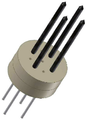
히터는 핀 히터(pin heater)일 수 있다. The heater may be a pin heater.
바람직하게는, 히터는 설치 부분들 둘레로 절연 물질을 더 포함한다. 이러한 절연 물질은 히터를 위한 강성(rigidity)을 제공할 수 있고, 또한 가열 부분의 전기 전도성 튜빙과 설치 부분의 전기 전도성 엘리먼트 사이에서 단락 회로(short circuit)를 방지할 수 있다. Preferably, the heater further comprises an insulating material around the installation parts. Such insulating material can provide rigidity for the heater and can also prevent short circuits between the electrically conductive tubing of the heating portion and the electrically conductive element of the installation portion.
본 발명의 다른 관점에 따라서, 에어로졸을 형성하도록 기질을 가열하기 위해, 본 발명의 제3 관점에 따른 하나 이상의 히터를 포함하는 전기적으로 가열되는 에어로졸-생성 시스템이 제공된다. 본 발명의 이 관점에 따르면, 에어로졸을 형성하도록 기질을 가열하기 위해, 본 발명의 제2 관점에 따른 하나 이상의 가열 소자를 포함하는 전기적으로 가열되는 에어로졸-생성 시스템 또한 제공된다. 본 발명의 실시 예들에 따른 전기적으로 가열되는 에어로졸-생성 시스템은 에어로졸을 형성하도록 기질을 가열하기 위해, 본 발명의 실시 예들에 따른 하나 이상의 핀 히터를 포함할 수 있다. According to another aspect of the present invention, an electrically heated aerosol-generating system is provided that includes one or more heaters according to the third aspect of the present invention for heating a substrate to form an aerosol. According to this aspect of the invention, there is also provided an electrically heated aerosol-generating system comprising at least one heating element according to the second aspect of the invention for heating the substrate to form an aerosol. An electrically heated aerosol-generating system according to embodiments of the present invention may include one or more fin heaters according to embodiments of the present invention to heat the substrate to form an aerosol.
바람직하게는, 본 발명의 임의의 관점의 전기적으로 가열되는 에어로졸-생성 시스템은 가열 소자들에게 파워를 공급하기 위한 파워 서플라이를 더 포함한다. 전기적으로 가열되는 에어로졸-생성 시스템은 각각의 가열 소자의 설치 부분 및 파워 서플라이에 연결된 전기적 하드웨어(electrical hardware)를 포함할 수 있다.Preferably, the electrically heated aerosol-generating system of any aspect of the present invention further comprises a power supply for powering the heating elements. The electrically heated aerosol-generating system may comprise electrical hardware connected to the power supply and the installation portion of each heating element.
본 발명의 실시 예들에 따른 전기적으로 가열되는 에어로졸-생성 시스템은 가열 소자들에게 파워를 공급하기 위한 재충전가능한 배터리와 같은 파워 소스(power source) 또는 파워 서플라이를 더 포함할 수 있다. 파워 서플라이는 전기적으로 가열되는 에어로졸-생성 시스템 내에 포함된 파워 셀(power cell)일 수 있다. 파워 서플라이는 리튬-이온(Lithium-ion) 배터리 또는 그 변형물들, 예컨대 리튬-이온 폴리머(polymer) 배터리일 수 있다. 이와 달리, 파워 서플라이는 니켈-금속 수소(Nickel-metal hydride) 배터리 또는 니켈 카드뮴(Nickel cadmium) 배터리 또는 연료 셀(fuel cell)일 수 있다. 시스템은 각각의 가열 소자의 설치 부분 및 파워 서플라이에 연결된 전기적 하드웨어를 더 포함할 수 있다. 바람직하게는, 본 발명의 실시 예들에 따른 전기적으로 가열되는 에어로졸-생성 시스템은 소프트웨어에 의해 프로그램가능한 전기적 하드웨어를 포함한다.The electrically heated aerosol-generating system according to embodiments of the present invention may further comprise a power source or power supply, such as a rechargeable battery for powering the heating elements. The power supply may be a power cell included in an electrically heated aerosol-generating system. The power supply may be a lithium-ion battery or variants thereof, such as a lithium-ion polymer battery. Alternatively, the power supply may be a nickel-metal hydride battery or a nickel cadmium battery or a fuel cell. The system may further include electrical hardware coupled to the installation portion and power supply of each heating element. Preferably, the electrically heated aerosol-generating system according to embodiments of the present invention includes electrical hardware programmable by software.
바람직하게는, 본 발명의 실시 예들에 따른 전기적으로 가열되는 에어로졸-생성 시스템은 에어로졸-형성 기질을 수용하기 위한 하우징(housing)을 더 포함한다. 하우징은 또한 쉘(shell)을 포함할 수 있다.Preferably, the electrically heated aerosol-generating system according to embodiments of the present invention further comprises a housing for receiving the aerosol-forming substrate. The housing may also include a shell.
바람직하게는, 전기적으로 가열되는 에어로졸-생성 시스템은 사용자가 취하는 퍼프(puff)를 나타내는 공기 흐름을 검출하기 위한 센서를 더 포함하고, 온도 센서를 더 포함한다. 공기 흐름 센서는 전자-기계(electro-mechanical) 장치일 수 있다. 이와 달리, 공기 흐름 센서는: 기계 장치, 광학(optical) 장치, 광학-기계(opto-mechanical) 장치, 및 MEMS(micro electro-mechanical system) 기반 센서 중의 어느 하나일 수 있다. 이와 달리, 전기적으로 가열되는 에어로졸-생성 시스템은 퍼프를 시작하는 사용자를 위해 수동으로 작동가능한 스위치를 포함할 수 있다. 온도 센서는 히터의 온도 또는 가열 소자의 온도 또는 에어로졸-형성 기질의 온도를 검출할 수 있다.Preferably, the electrically heated aerosol-generating system further comprises a sensor for detecting an air flow indicative of the puff that the user takes and further comprises a temperature sensor. The air flow sensor may be an electro-mechanical device. Alternatively, the air flow sensor can be any one of: a mechanical device, an optical device, an opto-mechanical device, and a micro electro-mechanical system (MEMS) based sensor. Alternatively, the electrically heated aerosol-generating system may include a manually operable switch for the user to start the puff. The temperature sensor can detect the temperature of the heater or the temperature of the heating element or the temperature of the aerosol-forming substrate.
바람직하게는, 전기적으로 가열되는 에어로졸-생성 시스템은 하나 이상의 가열 소자가 작동될 때를 표시하는 인디케이터(indicator)를 더 포함한다. 인디케이터는 하나 이상의 가열 소자가 작동될 때 작동되는 발광체(light)를 포함할 수 있다.Preferably, the electrically heated aerosol-generating system further comprises an indicator indicating when one or more heating elements are activated. The indicator may include a light that is activated when one or more heating elements are activated.
본 발명의 제4 관점에 따라서, 전기적으로 가열되는 에어로졸-생성 시스템에서 에어로졸-형성 기질을 가열하기 위한 가열 소자를 제조하는 방법이 제공되는데, 상기 방법은: a) 전기 전도성 튜빙에 전기 전도성 엘리먼트의 제1 말단을 삽입하고, 전기 전도성 엘리먼트의 제2 말단이 튜빙 외부에 노출되는 단계; b) 전기 전도성 엘리먼트의 제1 말단을 둘러싸는, 전기 전도성 튜빙 내에 전기 절연 플러그를 제공하는 단계; 및 c) 전기 전도성 튜빙에 전기 전도성 엘리먼트를 전기적으로 연결하는 전기 저항성 부분을 형성하는 단계를 포함하고, 전기 전도성 엘리먼트 및 전기 전도성 튜빙은 세장형이다.According to a fourth aspect of the invention, there is provided a method of manufacturing a heating element for heating an aerosol-forming substrate in an electrically heated aerosol-generating system, the method comprising: a) an electrically conductive element in an electrically conductive tubing; Inserting a first end and exposing a second end of the electrically conductive element to the outside of the tubing; b) providing an electrically insulating plug in the electrically conductive tubing surrounding the first end of the electrically conductive element; And c) forming an electrically resistive portion electrically connecting the electrically conductive element to the electrically conductive tubing, wherein the electrically conductive element and the electrically conductive tubing are elongate.
사용시, 전기 전도성 튜빙과 전기 저항성 부분 양쪽 모두는 에어로졸-형성 기질과 적어도 부분적으로 접촉한다. 가열 소자는 가열 부분 및 설치 부분을 포함할 수 있다. 전기 전도성 튜빙, 플러그, 및 전기 전도성 엘리먼트의 제1 말단이 함께 가열 소자의 가열 부분을 형성할 수 있다. 전기 전도성 엘리먼트의 노출된 제2 말단은 가열 소자의 설치 부분을 형성할 수 있다.In use, both the electrically conductive tubing and the electrically resistant portion are at least partially in contact with the aerosol-forming substrate. The heating element may comprise a heating portion and an installation portion. The electrically conductive tubing, the plug, and the first end of the electrically conductive element may together form the heating portion of the heating element. The exposed second end of the electrically conductive element may form an installation portion of the heating element.
본 방법은 전기적으로 가열되는 에어로졸-생성 시스템에 사용하기 위한 가열 소자를 제조하는 간단한 방법을 제공한다. 전기적으로 가열되는 에어로졸-생성 시스템은 전기적으로 동작하는 흡연 시스템을 포함할 수 있다.The method provides a simple method of manufacturing a heating element for use in an electrically heated aerosol-generating system. The electrically heated aerosol-generating system can include an electrically operated smoking system.
일 실시 예에서, 전기 전도성 엘리먼트의 제1 말단을 둘러싸는, 전기 전도성 튜빙 내에 전기 절연 플러그를 제공하는 단계 b)는 전기 전도성 엘리먼트의 제1 말단 둘레로 전기 절연 플러그를 제공하는 단계와 전기 전도성 엘리먼트의 제1 말단을 삽입하는 단계 a)와 동시에 전기 절연 플러그를 삽입하는 단계를 포함한다.In one embodiment, the step b) of providing an electrically insulating plug in the electrically conductive tubing surrounding the first end of the electrically conductive element comprises the steps of providing an electrically insulating plug around the first end of the electrically conductive element and the electrically conductive element. And inserting an electrically insulating plug simultaneously with step a) of inserting a first end of the.
대안적인 실시 예에서, 전기 전도성 엘리먼트의 제1 말단을 둘러싸는, 전기 전도성 튜빙 내에 전기 절연 플러그를 제공하는 단계 b)는 전기 전도성 엘리먼트의 제1 말단을 둘러싸기 위하여 전기 절연 페이스트를 전기 전도성 튜빙 안으로 삽입하는 단계를 포함하고, 페이스트는 건조시 전기 절연 플러그를 형성한다. 이 실시 예에서, 바람직하게는, 전기 절연 페이스를 전기 전도성 튜빙 안으로 삽입하는 단계는 튜빙의 일 말단과 튜빙의 다른 말단 사이에 압력차(pressure differential)를 적용하는 단계를 포함한다. 이것은 전기 절연 페이스트를 튜빙 안으로 빨아들이거나(sucking) 또는 흡입하는(drawing) 단계를 포함할 수 있다. 대안적으로 또는 부가적으로, 이것은 전기 절연 페이스트를 튜빙 안으로 밀어넣거나(pushing), 펌핑하거나(pumping), 또는 주입하는(injecting) 단계를 포함할 수 있다. 바람직하게는, 본 방법은, 전기 절연 페이스트를 전기 전도성 튜빙 안으로 삽입하는 단계 이후에, 플러그를 형성하도록 페이스트를 건조시키기 위해서 페이스트를 가열하는 단계를 더 포함한다. 페이스트를 가열하는 단계는 전도성 튜빙 및 페이스트상에 뜨거운 공기를 불어넣는 단계를 포함할 수 있다. 임의의 다른 적절한 가열 수단이 이용될 수 있다. 페이스트의 건조는 바람직하게는 결과로 얻어지는 절열 플러그가 적절한 밀도 및 구조를 가져서 적절한 절연 속성을 가지도록 주의하여 제어된다. 전기 절연 페이스트는 전기 전도성 튜빙 안으로 삽입되도록 충분히 유동적이거나(fluid), 가소성이 좋거나(plastic), 또는 신축성(elastic)이 있어야 한다. 바람직하게는, 전기 절연 페이스트는 용매, 예컨대 물에 녹는 전기 절연 파우더를 포함한다. 페이스트를 위해 사용된 물질의 타입 및 농도는 가열 소자의 속성에 영향을 미칠 것이다.In an alternative embodiment, the step b) of providing an electrically insulating plug in the electrically conductive tubing surrounding the first end of the electrically conductive element comprises introducing an electrically insulating paste into the electrically conductive tubing to surround the first end of the electrically conductive element. Inserting, and the paste forms an electrically insulating plug upon drying. In this embodiment, preferably, inserting the electrically insulating face into the electrically conductive tubing includes applying a pressure differential between one end of the tubing and the other end of the tubing. This may include sucking or drawing the electrical insulation paste into the tubing. Alternatively or additionally, this may include pushing, pumping, or injecting the electrical insulation paste into the tubing. Preferably, the method further comprises heating the paste to dry the paste to form a plug after inserting the electrically insulating paste into the electrically conductive tubing. Heating the paste may include blowing hot air onto the conductive tubing and the paste. Any other suitable heating means can be used. Drying of the paste is preferably controlled carefully so that the resulting glow plugs have the appropriate density and structure and have the appropriate insulating properties. The electrically insulating paste must be fluid, plastic, or elastic enough to be inserted into the electrically conductive tubing. Preferably, the electrically insulating paste comprises an electrically insulating powder that is soluble in a solvent such as water. The type and concentration of material used for the paste will affect the properties of the heating element.
전기 전도성 엘리먼트의 제1 말단에서 전기 전도성 튜빙과 전기 전도성 엘리먼트를 전기적으로 연결함으로써 전기 저항성 부분이 가열 소자의 제1 말단에서 생성될 수 있다. 대안적으로 또는 부가적으로, 적어도 하나의 전기 저항성 부분을 생성하는 단계는 전기 전도성 엘리먼트의 제1 말단과 전기 전도성 엘리먼트의 제2 말단 사이에서의 한 개의 또는 두 개의 또는 세 개의 또는 네 개의 또는 그 이상의 포인트(point)에서 전기 저항성 엘리먼트들을 형성하도록 전기 전도성 엘리먼트와 전기 전도성 튜빙을 전기적으로 연결하는 단계를 포함한다. 이 추가적인 전기 저항성 부분들은 전기 저항성 접합들이라고 할 수 있다.An electrically resistive portion can be produced at the first end of the heating element by electrically connecting the electrically conductive tubing and the electrically conductive element at the first end of the electrically conductive element. Alternatively or additionally, the step of creating at least one electrically resistive portion may comprise one or two or three or four or four between the first end of the electrically conductive element and the second end of the electrically conductive element. Electrically connecting the electrically conductive element and the electrically conductive tubing to form electrically resistive elements at the above points. These additional electrically resistive portions can be referred to as electrically resistive junctions.
바람직하게는, 전기 전도성 엘리먼트의 제1 말단을 전기 전도성 튜빙 안으로 삽입하는 단계는 전기 전도성 엘리먼트의 길이 L 부분을 전기 전도성 튜빙 안으로 삽입하는 단계를 포함하고, L은 가열 소자의 가열 부분의 요구되는 길이이다. 이와 달리, 본 방법은 요구되는 길이 L의 가열 부분을 형성하도록 튜빙, 플러그, 및 전기 전도성 엘리먼트의 제1 말단을 절단하는 단계를 더 포함할 수 있다. 이 경우에, 절단하는 단계는 전기 전도성 엘리먼트의 제1 말단의 맨 끝(extremity)에서 저항성 부분 또는 엘리먼트를 생성하는 단계와 결합될 수 있다.Preferably, inserting the first end of the electrically conductive element into the electrically conductive tubing comprises inserting a length L portion of the electrically conductive element into the electrically conductive tubing, where L is the desired length of the heating portion of the heating element. to be. Alternatively, the method may further comprise cutting the first end of the tubing, plug, and electrically conductive element to form a heating portion of the required length L. In this case, cutting may be combined with creating a resistive portion or element at the extreme of the first end of the electrically conductive element.
바람직하게는, 전기 전도성 엘리먼트의 노출된 제2 말단은 길이 m을 가진다. 다시 말해, 전기 전도성 엘리먼트는 길이 m만큼 전기 전도성 튜빙으로부터 돌출한다. m은 가열 소자의 설치 부분의 요구되는 길이일 수 있다. 이와 달리, 본 방법은 요구되는 길이 m의 설치 부분을 형성하기 위해서 전기 전도성 엘리먼트의 제2 말단을 절단하는 단계를 더 포함할 수 있다.Preferably, the exposed second end of the electrically conductive element has a length m . In other words, the electrically conductive element protrudes from the electrically conductive tubing by length m . m can be the required length of the installation part of the heating element. Alternatively, the method may further comprise cutting the second end of the electrically conductive element to form an installation portion of the required length m .
본 발명의 제5 관점에 따르면, 전기적으로 가열되는 에어로졸-생성 시스템에서 에어로졸-형성 기질을 가열하기 위한 히터를 제조하는 방법이 제공되는데, 상기 방법은: 본 발명의 제4 관점의 방법에 따른 하나 이상의 가열 소자를 제조하는 단계; 홀더 내에 하나 이상의 가열 소자를 설치하고, 각각의 가열 소자의 가열 부분은 홀더 외부에 노출되는 단계; 및 각각의 전기 전도성 엘리먼트를 통하여 전류를 공급하기 위하여 파워 서플라이에 각각의 가열 소자의 설치 부분을 연결하는 단계를 포함한다.According to a fifth aspect of the invention, there is provided a method of manufacturing a heater for heating an aerosol-forming substrate in an electrically heated aerosol-generating system, the method comprising: one according to the method of the fourth aspect of the invention Manufacturing the heating element; Installing at least one heating element in the holder, the heating portion of each heating element being exposed outside the holder; And connecting the installation portion of each heating element to the power supply for supplying current through each electrically conductive element.
본 방법은 설치 부분들 위로 절연 물질을 적용하는 단계를 더 포함할 수 있다.The method may further comprise applying an insulating material over the installation parts.
바람직하게는, 홀더는 말단 히터(end heater)와 같은 추가적인 히터를 포함한다. 홀더는 에어로졸-형성 기질을 둘러쌀 수 있다. 가열 소자는 에어로졸-형성 기질의 중간을 통해 지나갈 수 있다.Preferably, the holder comprises an additional heater, such as an end heater. The holder may surround the aerosol-forming substrate. The heating element may pass through the middle of the aerosol-forming substrate.
에어로졸-형성 기질은 바람직하게는 가열시 기질로부터 방출되는 휘발성 담배 풍미 화합물(flavour compound)을 함유하는 담배-함유(tobacco-containing) 물질을 포함한다. 에어로졸-형성 기질은 비-담배(non-tobacco) 물질을 포함할 수 있다. 에어로졸-형성 기질은 담배-함유 물질과 비-담배 함유 물질을 포함할 수 있다.The aerosol-forming substrate preferably comprises a tobacco-containing material containing a volatile tobacco flavor compound released from the substrate upon heating. The aerosol-forming substrate may comprise a non-tobacco material. Aerosol-forming substrates may include tobacco-containing materials and non-tobacco containing materials.
바람직하게는, 에어로졸-형성 기질은 에어로졸 포머(former)를 더 포함한다. 적절한 에어로졸 포머의 예는 글리세린(glycerine) 및 프로필렌 글리콜(propylene glycol)이다.Preferably, the aerosol-forming substrate further comprises an aerosol former. Examples of suitable aerosol formers are glycerine and propylene glycol.
에어로졸-형성 기질은 바람직하게는 고체 기질이다. 이 고체 기질은 예컨대, 허브 잎, 담배 잎, 담배 주엽맥(ribs)의 단편, 환원된(reconstituted) 담배, 압출된(extruded) 담배와 같이 균질화된(homogenised) 담배, 및 팽창된(expanded) 담배 중 하나 이상을 함유하는 파우더(powder), 그래뉼(granule), 펠레(pellet), 스레드(shred), 스파게티(spaghetti), 스트립(strip) 또는 시트(sheet) 중 하나 이상을 포함할 수 있다. 고체 기질은 느슨한(loose) 형태로 있을 수 있고, 적절한 용기(container) 또는 카트리지(cartridge) 내에서 제공될 수도 있다. 선택적으로, 고체 에어로졸-형성 기질은 기질의 가열 시 방출될 추가적인 담배 또는 비-담배 휘발성 풍미 화합물을 포함할 수 있다.The aerosol-forming substrate is preferably a solid substrate. These solid substrates include, for example, herb leaves, tobacco leaves, fragments of tobacco ribs, reconstituted tobacco, homogenised tobacco, such as extruded tobacco, and expanded tobacco. It may include one or more of powder, granule, pellet, thread, spaghetti, strip or sheet containing one or more of these. The solid substrate may be in loose form and may be provided in a suitable container or cartridge. Optionally, the solid aerosol-forming substrate may comprise additional tobacco or non-tobacco volatile flavor compounds to be released upon heating of the substrate.
선택적으로, 고체 기질은 열적으로 안정한 캐리어(carrier) 상에서 제공될 수 있고, 또는 열적으로 안정한 캐리어 내에 내장될 수도 있다. 캐리어는 파우더, 그래뉼, 펠레, 스레드, 스파게티, 스트립 또는 시트의 형태를 취할 수 있다. 이와 달리, 캐리어는 그 내부 표면상에, 또는 그 외부 표면상에, 또는 그 내부 및 외부 표면상에 증착된 고체 기질로 이루어진 얇은 레이어(layer)를 갖는 튜브모양의 캐리어일 수 있다. 이러한 튜브모양의 캐리어는 예컨대, 종이, 또는 종이와 같은 물질, 부직포 탄소 섬유 매트(non-woven carbon fibre mat), 저 질량 개방 메쉬 금속성 스크린(low mass open mesh metallic screen), 또는 구멍이 뚫린 금속성 호일(perforated metallic foil), 또는 임의의 다른 열적으로 안정한 폴리머 매트릭스(polymer matrix)로 이루어질 수 있다.Optionally, the solid substrate may be provided on a thermally stable carrier or may be embedded within the thermally stable carrier. The carrier may take the form of a powder, granule, pellet, thread, spaghetti, strip or sheet. Alternatively, the carrier may be a tubular carrier having a thin layer of solid substrate deposited on or on its inner surface, or on its inner and outer surfaces. Such tubular carriers may be, for example, paper or a material such as paper, non-woven carbon fiber mat, low mass open mesh metallic screen, or perforated metallic foil. (perforated metallic foil), or any other thermally stable polymer matrix.
고체 기질은 예컨대, 시트, 거품(foam), 젤(gel), 또는 슬러리(slurry)의 형태로 캐리어의 표면상에 증착될 수 있다. 고체 기질은 캐리어의 전체 표면상에 증착될 수 있고, 또는 이와 달리, 사용하는 동안 비-균질한(non-uniform) 풍미 전달을 제공하기 위해 패턴(pattern) 내에 증착될 수 있다. Solid substrates may be deposited on the surface of the carrier, for example in the form of sheets, foam, gels, or slurries. Solid substrates may be deposited on the entire surface of the carrier, or alternatively, may be deposited in a pattern to provide a non-uniform flavor transfer during use.
이와 달리, 캐리어는 담배 성분들이 포함된 부직포 직물 또는 섬유 다발(bundle)일 수 있다. 부직포 직물 또는 섬유 다발은 예컨대 탄소 섬유, 천연 셀룰로오스 섬유, 또는 셀룰로오스 파생 섬유를 포함할 수 있다.Alternatively, the carrier may be a nonwoven fabric or fiber bundle containing tobacco components. Nonwoven fabrics or fiber bundles may include, for example, carbon fibers, natural cellulose fibers, or cellulose derived fibers.
게다가, 당업자에게 알려져 있는 바와 같이, 에어로졸은 공기와 같은 기체 내에서의 고체 입자들 또는 액체 방울들의 서스펜션(suspension)이다. 본 에어로졸은 공기와 같은 기체 내에서의 고체 입자들 또는 액체 방울들의 서스펜션일 수 있다.In addition, as is known to those skilled in the art, an aerosol is a suspension of solid particles or liquid droplets in a gas such as air. The present aerosol may be a suspension of solid particles or liquid drops in a gas such as air.
바람직하게는, 기질은 별개의 흡연 물품의 일부를 형성하고, 사용자는 흡연 물품상에서 직접 퍼프(puff)할 수 있다.Preferably, the substrate forms part of a separate smoking article, and the user can puff directly on the smoking article.
흡연 물품은 약 30 mm와 100 mm 사이에서 전체 길이를 가질 수 있다. 흡연 물품은 약 5 mm와 약 13 mm 사이에서 외부 지름을 가질 수 있다. 흡연 물품은 필터 플러그(filter plug)를 포함할 수 있다. 필터 플러그는 흡연 물품의 다운스트림 말단(downstream end)에 위치할 수 있다. 필터 플러그는 셀룰로오스 아세테이트(cellulose acetate) 필터 플러그일 수 있다. 필터 플러그는 바람직하게는 길이가 약 7 mm이지만, 약 5 mm 내지 약 10 mm 사이의 길이를 가질 수 있다.Smoking articles may have an overall length between about 30 mm and 100 mm. The smoking article may have an outer diameter between about 5 mm and about 13 mm. The smoking article may comprise a filter plug. The filter plug may be located at the downstream end of the smoking article. The filter plug may be a cellulose acetate filter plug. The filter plug is preferably about 7 mm long but may have a length between about 5 mm and about 10 mm.
바람직하게는, 흡연 물품은 시가렛이다. 바람직한 실시 예에서, 흡연 물품은 40 mm와 50 mm 사이에서 전체 길이를 가진다. 바람직하게는, 흡연 물품은 약 45 mm의 전체 길이를 가진다. 흡연 물품이 약 7.2 mm의 외부 지름을 가지는 것 또한 바람직하다. 바람직하게는, 에어로졸-형성 기질은 담배를 포함한다. 게다가, 에어로졸-형성 기질은 약 10 mm의 길이를 가질 수 있다. 하지만, 에어로졸-형성 기질이 12 mm의 길이를 가지는 것이 가장 바람직하다.Preferably the smoking article is cigarette. In a preferred embodiment, the smoking article has an overall length between 40 mm and 50 mm. Preferably, the smoking article has a total length of about 45 mm. It is also desirable for the smoking article to have an outer diameter of about 7.2 mm. Preferably, the aerosol-forming substrate comprises tobacco. In addition, the aerosol-forming substrate may have a length of about 10 mm. However, it is most preferred that the aerosol-forming substrate has a length of 12 mm.
게다가, 에어로졸-형성 기질의 지름은 또한 약 5 mm와 약 12 mm 사이일 수 있다.In addition, the diameter of the aerosol-forming substrate may also be between about 5 mm and about 12 mm.
흡연 물품은 외부 종이 래퍼(wrapper)를 포함할 수 있다.The smoking article may include an outer paper wrapper.
게다가, 흡연 물품은 에어로졸-형성 기질과 필터 플러그 사이의 분리(separation)를 포함할 수 있다. 이 분리는 약 18 mm일 수 있지만, 약 5 mm 내지 약 25 mm의 범위 내에 있을 수 있다.In addition, the smoking article may comprise a separation between the aerosol-forming substrate and the filter plug. This separation may be about 18 mm, but may be in the range of about 5 mm to about 25 mm.
에어로졸-형성 기질은 이와 달리 액체 기질일 수 있다. 에어로졸-형성 기질은 이와 달리 임의의 다른 종류의 기질, 예컨대 기체 기질 또는 기질의 다양한 타입들의 임의의 조합일 수 있다.The aerosol-forming substrate may alternatively be a liquid substrate. The aerosol-forming substrate may alternatively be any other kind of substrate, such as a gaseous substrate or any combination of various types of substrates.
동작하는 동안, 기질은 전기적으로 가열되는 에어로졸-생성 시스템 내부에 완전히 포함될 수 있다. 이러한 경우에, 사용자는 전기적으로 가열되는 에어로졸-생성 시스템의 마우스피스(mouthpiece) 상에서 퍼프(puff)할 수 있다. 이와 달리, 동작하는 동안, 기질은 전기적으로 가열되는 흡연 시스템 내에 부분적으로 포함될 수 있다. 기질은 별개의 물품의 일부를 형성할 수 있고, 사용자는 별개의 물품 상에서 직접 퍼프할 수 있다.During operation, the substrate may be completely contained within the electrically heated aerosol-generating system. In such a case, the user may puff on the mouthpiece of the electrically heated aerosol-generating system. Alternatively, during operation, the substrate may be partly included in an electrically heated smoking system. The substrate can form part of a separate article and the user can puff directly on the separate article.
바람직하게는, 가열 소자는 에어로졸-형성 기질의 중심을 통해서 지나가는 가열 바늘(needle), 핀(pin), 또는 로드(rod)로서 이용된다. 이러한 내부 히터들은 열적 에너지가 원 위치에(in situ) 즉, 에어로졸 포머에 직접 전달되기 때문에 이점이 있다. 에어로졸-형성 기질에 의해서 생성된 열 절연 장벽(heat insulation barrier)이 감소될 수 있다. 내부 히터들은 또한 가열 소자상으로의 에어로졸의 응결(condensation)을 최소화하는 경향이 있어서, 요구되는 유지보수를 감소시킨다. 가열 소자는 추가적인 히터들, 예컨대 디스크, 또는 말단 히터, 또는 가열 플레이트(heating plate)와 함께 사용될 수 있다.Preferably, the heating element is used as a heating needle, pin, or rod passing through the center of the aerosol-forming substrate. These internal heaters are advantageous because thermal energy is delivered in situ , ie directly to the aerosol former. The heat insulation barrier produced by the aerosol-forming substrate can be reduced. Internal heaters also tend to minimize condensation of the aerosol onto the heating element, thus reducing the maintenance required. The heating element can be used with additional heaters, such as a disk, or end heater, or heating plate.
가열 소자는 전도에 의해 에어로졸-형성 기질을 가열하도록 이용될 수 있다. 가열 소자는 기질 또는 기질이 증착된 캐리어와 적어도 부분적으로 접촉할 수 있다. 이와 달리, 가열 소자로부터의 열은 열 전도성 엘리먼트에 의해서 기질에 전도될 수 있다. 이와 달리, 제조된 가열 소자는 사용하는 동안 전기적으로 가열되는 에어로졸-생성 시스템을 통해서 흡입된 들어오는 주변 공기(ambient air)로 열을 전달할 수 있고, 차례로 대류에 의해서 에어로졸-형성 기질을 가열한다. 주변 공기는 에어로졸-형성 기질을 통과해서 지나가기 전에 가열될 수 있고 또는 주변 공기는 기질을 통해서 먼저 흡입된 후에 가열될 수 있다.The heating element can be used to heat the aerosol-forming substrate by conduction. The heating element may be at least partially in contact with the substrate or the carrier on which the substrate is deposited. Alternatively, heat from the heating element can be conducted to the substrate by a thermally conductive element. Alternatively, the manufactured heating element can transfer heat to the incoming ambient air sucked through an aerosol-generating system that is electrically heated during use, which in turn heats the aerosol-forming substrate by convection. The ambient air may be heated before passing through the aerosol-forming substrate or the ambient air may be heated after first being sucked through the substrate.
전기 전도성 엘리먼트는 바람직하게는 와이어를 포함한다. 전기 전도성 엘리먼트는 바람직하게는 금속성이다. 바람직한 실시 예에서, 전기 전도성 엘리먼트는 구리선이다. 전기 전도성 엘리먼트는 바람직하게는 원형의 단면을 가진다. 하지만, 전기 전도성 엘리먼트는 임의의 적절한 단면 형상을 가질 수 있다.The electrically conductive element preferably comprises a wire. The electrically conductive element is preferably metallic. In a preferred embodiment, the electrically conductive element is copper wire. The electrically conductive element preferably has a circular cross section. However, the electrically conductive element can have any suitable cross-sectional shape.
전기 전도성 튜빙은 바람직하게는 금속성 튜빙을 포함한다. 바람직하게는, 전기 전도성 튜빙은 전기 전도성 엘리먼트와는 다른 물질을 포함한다. 바람직한 실시 예에서, 전기 전도성 튜빙은 스테인리스강 튜빙이다. 이와 달리, 전기 전도성 튜빙은 Timetal ®(티타늄 기반 합금) 또는 니켈(Nickel) 기반 합금 튜빙이다. 전기 전도성 튜빙은 바람직하게는 원형 단면을 가진다. 하지만, 전기 전도성 튜빙은 임의의 적절한 단면 형상을 가질 수 있다. Timetal®은 티타늄 메탈 코퍼레이션(Titanium Metals Corporation, 1999 Broadway Suite 4300, Denver, Colorado)의 등록상표이다.The electrically conductive tubing preferably comprises a metallic tubing. Preferably, the electrically conductive tubing comprises a material different from the electrically conductive element. In a preferred embodiment, the electrically conductive tubing is a stainless steel tubing. In contrast, electrically conductive tubing is a Timetal ® (titanium based alloy) or nickel based alloy tubing. The electrically conductive tubing preferably has a circular cross section. However, the electrically conductive tubing may have any suitable cross sectional shape. Timetal® is a registered trademark of Titanium Metals Corporation, 1999 Broadway Suite 4300, Denver, Colorado.
전기 전도성 튜빙은 실질적으로 원형인 단면을 가질 수 있다. 이와 달리, 튜빙은 정사각형, 삼각형, 또는 타원 단면을 가질 수 있다. 전기 전도성 튜빙의 단면 영역은 전기 전도성 엘리먼트의 단면 영역보다 더 클 수 있다. 이 경우에, 실질적으로 환형(annular)인 전기 절연 플러그는 내부 전기 전도성 엘리먼트와 외부 전기 전도성 튜빙 사이에서 전기 절연체를 형성하기 위해서 전기 전도성 엘리먼트 둘레로 제공될 수 있다.The electrically conductive tubing may have a substantially circular cross section. Alternatively, the tubing may have a square, triangular, or elliptical cross section. The cross sectional area of the electrically conductive tubing may be larger than the cross sectional area of the electrically conductive element. In this case, a substantially annular electrically insulating plug can be provided around the electrically conductive element to form an electrical insulator between the inner electrically conductive element and the outer electrically conductive tubing.
전기 전도성 엘리먼트, 플러그, 전기 전도성 튜빙의 상대적인 치수는 가열 소자의 속성, 예컨대 하지만 이에 한정되지 않는, 전기 파워의 단위당 가열 소자의 온도 증가 및 가열 소자 길의 단위당 온도 증가에 영향을 미칠 것이다.The relative dimensions of the electrically conductive element, plug, electrically conductive tubing will affect the properties of the heating element, such as, but not limited to, increasing the temperature of the heating element per unit of electrical power and increasing the temperature per unit of the heating element length.
본 발명의 제6 관점에 따라서, 특히 전기적으로 가열되는 에어로졸 생성 시스템에서, 기질을 가열하기 위해 가열 소자로서 본 발명의 제2 관점에 따른 가열 소자의 이용이 제공된다.According to a sixth aspect of the invention, in particular in an electrically heated aerosol generating system, the use of the heating element according to the second aspect of the invention is provided as a heating element for heating the substrate.
본 발명의 일 관점과 관련해서 설명된 특징들은 본 발명의 다른 관점에도 적용될 수 있다.Features described in connection with one aspect of the invention may be applied to other aspects of the invention.
도 1 내지 9는 본 발명의 방법의 일 실시 예의 연속적인 단계들을 도시하고, 도 9는 일 실시 예에 따른 결과로 얻어지는 가열 소자를 도시한다;
도 10의 (a)는 본 발명의 일 실시 예에 따른 가열 소자의 단면도를 도시한다;
도 10의 (b)는 가열 소자를 따라서 거리의 함수로서 그려진, 도 10의 (a)의 가열 소자의 저항을 도시하는 개략도이다;
도 10의 (c)는 도 10의 (a)의 가열 소자의 한 부분이 어떻게 가열 소자의 나머지 부분보다 더 높은 저항을 가지는지를 도시하는 개략적 회로도이다;
도 10의 (d)는 도 10의 (a)의 가열 소자의 정상 상태 온도 프로파일(profile)을 도시한다;
도 11의 (a)는 본 발명의 다른 실시 예에 따른 가열 소자의 단면도를 도시한다;
도 11의 (b)는 가열 소자를 따라서 거리의 함수로서 그려진, 도 11의 (a)의 가열 소자의 저항을 도시하는 개략도이다;
도 11의 (c)는 도 11의 (a)의 가열 소자의 하나 이상의 부분이 어떻게 가열 소자의 나머지 부분보다 더 높은 저항을 가지는지를 도시하는 개략적 회로도이다;
도 11의 (d)는 도 11의 (a)의 가열 소자의 정상 상태 온도 프로파일을 도시한다; 그리고
도 12는 본 발명의 일 실시 예에 따라서 히터를 형성하는 실질적으로 정사각형 모양의 어레이로 조립된 4 개의 가열 소자를 도시한다.1 to 9 show the successive steps of one embodiment of the method of the invention, and FIG. 9 shows the resulting heating element according to one embodiment;
10 (a) shows a sectional view of a heating element according to an embodiment of the present invention;
FIG. 10 (b) is a schematic diagram showing the resistance of the heating element of FIG. 10 (a), drawn as a function of distance along the heating element;
FIG. 10C is a schematic circuit diagram showing how one part of the heating element of FIG. 10A has a higher resistance than the rest of the heating element;
(D) of FIG. 10 shows a steady state temperature profile of the heating element of FIG. 10 (a);
11 (a) shows a cross-sectional view of a heating element according to another embodiment of the present invention;
(B) of FIG. 11 is a schematic diagram showing the resistance of the heating element of FIG. 11 (a), drawn as a function of distance along the heating element;
FIG. 11C is a schematic circuit diagram showing how one or more portions of the heating element of FIG. 11A have a higher resistance than the rest of the heating element;
FIG. 11D shows the steady state temperature profile of the heating element of FIG. 11A; And
12 illustrates four heating elements assembled into a substantially square shaped array forming a heater according to one embodiment of the invention.
본 발명의 실시 예가 첨부 도면들을 참조하여 단지 예로서 더 설명될 것이다.Embodiments of the invention will be further described by way of example only with reference to the accompanying drawings.
도 1 내지 9를 참조하면, 절연 페이스트(insulating paste)(103)를 담고 있는 필링 챔버(filling chamber)(101) 및 제1 전기 전도성 엘리먼트가 제공된다. 제1 전기 전도성 엘리먼트는 구리선(105)일 수 있다. 필링 챔버(101)는 노즐 말단(nozzle end)(107)을 가진다. 제2 전기 전도성 엘리먼트 또한 제공된다. 제2 전기 전도성 엘리먼트는 구리선을 수용(receive)하기 위해 실질적으로 튜브모양의(tubular) 전기 전도성 튜브(tube)(109)일 수 있다. 도 1 내지 9는 일정한 비율로 도시되지 않았다는 점에 유의하라.1 through 9, a filling
도 1에 도시된 제1 단계에서, 튜브(109)는 평평한 표면을 획득하기 위하여 톱(saw)(111)을 가지고 절단(cut)된다. 이것은 화살표 201에 의해서 제시된다.In the first step shown in FIG. 1, the
도 2에 도시된 제2 단계에서, 튜브(109)의 톱질된 평평한 말단은 필링 챔버(101)의 외벽(outer wall)에 맞닿도록 유지된다. 이것은 화살표 202에 의해서 제시된다.In the second step shown in FIG. 2, the sawed flat end of the
도 3에 도시된 제3 단계에서, 튜브(109)의 평평한 말단이 필링 챔버(101)의 외벽에 대항해서 유지되는 동안, 구리선(105)은 튜브(109)를 향하고 튜브(109) 안으로 이동된다. 이것은 화살표 203에 의해서 제시된다. 이 실시 예에서, 도 3에서의 길이(301)는 가열 소자의 가열 부분(heating portion)을 위해서 요구되는 길이에 대응한다. 이것은 이하에서 더 설명될 것이다.In the third step shown in FIG. 3, the
도 4에 도시된 제4 단계에서, 튜브(109)의 평평한 말단이 필링 챔버(101)의 외벽에 대항해서 유지되는 동안, 페이스트(103)는 구리선(105)을 둘러싸기 위해서 튜브(109) 안으로 삽입된다. 이것은 필링 챔버(101)의 플린저(plunger)(401)에 압력을 가함으로써 달성된다. 이것은 화살표 204에 의해서 제시된다.In the fourth step shown in FIG. 4,
도 5에서 도시된 제5 단계에서, 튜브(109)의 평평한 말단이 필링 챔버(101)의 외벽에 대항해서 유지되는 동안, 튜브(109)가 가열되어, 페이스트(103)가 플러그(plug)(113)를 형성하도록 건조된다. 이것은 화살표 205에 의해서 제시된다. 제4 단계 및 제5 단계는 동시에 수행될 수 있다.In the fifth step shown in FIG. 5, while the flat end of the
도 6에서 도시된 제6 단계에서, 구리선(105)의 말단, 플러그(113), 및 튜브(109)는 가열 소자의 가열 부분의 원격 말단(remote end)을 형성하도록 전극(electrode)(115)들을 가지고 절단된다. 이것은 화살표 206에 의해서 제시된다. 이 절단은 제1 저항성 부분 또는 저항성 엘리먼트(117)를 생성하는데, 이것은 이하에서 더욱 상세하게 설명될 것이다.In the sixth step shown in FIG. 6, the end of the
선택적인 제7 단계가 도 7에서 도시되는데, 여기서 추가적인 저항성 부분 또는 저항성 엘리먼트(119)가 전극(115)들을 이용해서 생성된다. 이것은 화살표 207에 의해서 제시된다. 추가적 저항성 부분(119)은 선택적인 특징이다.An optional seventh step is shown in FIG. 7, wherein an additional resistive portion or
도 8에 도시된 제8 단계에서, 튜브(109)의 평평한 말단이 필링 챔버의 외벽으로부터 멀어지게 이동되어, 구리선(105)을 노출한다. 이것은 화살표 208에 의해서 제시된다.In the eighth step shown in FIG. 8, the flat end of the
도 9에서 도시된 마지막 제9 단계에서, 구리선(105)은 전극(115)들을 가지고 절단된다. 이것은 화살표 209에 의해서 제시된다. 결과로 얻어지는 가열 소자(121)는 가열 부분(123)과 설치(mounting) 및 연결(connection) 부분(125)을 포함한다. 도 9에서 길이(901)는 가열 소자의 설치 및 연결 부분(125)을 위해 요구되는 길이에 대응한다. 이것은 이하에서 더 설명될 것이다.In the last ninth step shown in FIG. 9, the
페이스트(103)는 가능한 걸쭉해야(thick) 하지만, 페이스트가 튜브(109) 안으로 삽입되는 것을 허용하기 위한 농도(consistency)를 가져야 한다. 페이스트는 용매, 예컨대 물에 절연 파우더(insulating powder)를 녹임으로써 형성될 수 있다. 절연 파우더는 예컨대, MiOx, 산화 마그네슘(magnesium oxide), 산화 알루미늄(aluminium oxide), 다른 금속 산화물 또는 염, 또는 이들의 하나 이상의 조합일 수 있지만 이에 한정되지 않는다. 부가적 물질 또한 페이스트에 포함될 수 있다. 페이스트가 건조한 경우에, 이것은 전기 절연체를 형성한다. 전기 절연체는 특정 브레이크 다운(break down) 전압까지 그것을 통해 흐르는 전류를 대체로 허용하지 않는 유전체(dielectric material)이다. 전류는 브레이크 다운 전압에서 흐르기 시작한다. 운모(mica)는 약 2000 kVcm-1의 브레이크 다운 전압을 가질 수 있다.The
도 5에 도시된 제5 단계에서, 튜브(109)와 페이스트(103)는 가열되어 플러그(113)를 형성한다. 이러한 가열은 튜브(109)상으로 뜨거운 공기를 불어넣어 또는 임의의 다른 적절한 수단에 의할 수 있다. 공기 드라이어(air dryer)가 가열 소자의 길이를 따라서 균등하게 페이스트를 건조시키기 위해서 이용될 수 있다. 페이스트가 건조될 때, 다소의 액체가 페이스트로부터 손실될 수 있어서, 페이스트는 수축될 수 있다. 추가적인 페이스트가 전기 전도성 튜빙(tubing) 안으로 삽입될 수 있고, 추가적인 페이스트를 건조시키고 삽입하는 단계는 플러그(113)를 형성하기 위해서 건조한 페이스트를 가지고 튜브모양의 가열 소자(109)를 완전히 채우도록 필요한 만큼 여러 번 반복될 수 있다.In the fifth step shown in FIG. 5, the
상술한 실시 예에서 구리선이 사용되었지만, 임의의 다른 적절한 금속선이 이용될 수 있다. 게다가, 제1 전기 전도성 엘리먼트는 와이어(wire)일 필요가 사실상 없다. 이것은 임의의 다른 전기 전도성 물질일 수 있다. 전기 전도성 엘리먼트는 단면이 원형 또는 실질적으로 원형일 필요가 없다. 이것은 임의의 단면 형상, 예컨대 사각형, 삼각형, 또는 타원형을 가질 수 있다. 게다가, 제1 전기 전도성 엘리먼트는 단일한 가닥의 와이어일 수 있다. 이와 달리, 제1 전도성 엘리먼트는 복수의 가닥의 와이어를 포함할 수 있다. 다른 적절한 금속의 예들은 금, 은, 백금, 및 티타늄을 포함한다. 일 실시 예에서, 구리선은 길이가 30 mm이고, 지름이 0.3 mm이다. 와이어는 릴(reel)에 부착될 수 있다. Although copper wire has been used in the embodiments described above, any other suitable metal wire may be used. In addition, the first electrically conductive element need not necessarily be a wire. This may be any other electrically conductive material. The electrically conductive element need not be circular or substantially circular in cross section. It may have any cross-sectional shape, such as square, triangular, or elliptical. In addition, the first electrically conductive element may be a single strand of wire. Alternatively, the first conductive element may comprise a plurality of strands of wire. Examples of other suitable metals include gold, silver, platinum, and titanium. In one embodiment, the copper wire is 30 mm long and 0.3 mm in diameter. The wire can be attached to a reel.
튜브(109)는 스테인리스강(stainless steel) 튜브일 수 있다. 이 튜브는 주사기 바늘일 수 있다. 튜브의 외부 지름은 약 0.5 mm 또는 1 mm 일 수 있다. 일 실시 예에서, 길이가 120 mm이고 지름이 0.8 mm인 Milian SA, Geneva에 의해서 제공된 BRA-4665643 바늘이 사용된다. 이 경우에, 페이스트는 주사기 바늘 안으로 페이스트를 빨아들임으로써 제4 단계에서 튜브 안으로 삽입될 수 있다. 이와 달리, 튜브(109)는 Ti-metal ® 튜브일 수 있다.
상술한 실시 예에서, 제1 단계에서, 필링 챔버 벽에 맞닿게(abut) 될 수 있는 평평한 표면을 획득하도록 튜브(109)를 절단하기 위하여 톱이 사용된다. 이와 달리, 이 절단은 다른 방법, 예컨대 레이저 빔(laser beam), 워터 제트(water jet), 또는 산소-보조 가스(oxygen-assisted gas)를 이용해서 수행될 수 있다.In the embodiment described above, in the first step, a saw is used to cut the
게다가, 상술한 실시 예에서, 도 6에서, 제1 저항성 부분(117)을 형성하기 위해서 구리선, 튜브, 및 플러그를 절단하기 위해서 전극(115)들이 사용된다. 하지만, 이러한 절단은 다른 방법, 예컨대 레이저 빔, 워터 제트, 또는 산소-보조 가스를 이용해서 열을 가지거나 가지지 않고 펜치 메커니즘을 이용해서 수행될 수 있다. 게다가, 상술한 실시 예에서, 도 7에서, 제2 저항성 부분을 형성하기 위해서 전극(115)들이 사용된다. 하지만, 이것은 다른 방법, 예컨대 레이저 빔, 워터 제트, 또는 산소-보조 가스를 이용해서 열을 가지거나 가지지 않고 펜치 메커니즘을 이용해서 수행될 수 있다. 게다가, 상술한 실시 예에서, 도 9에서, 구리선을 절단하기 위해서 전극(115)들이 사용된다. 하지만, 이것은 다른 방법, 예컨대 레이저 빔, 워터 제트, 또는 산소-보조 가스를 이용해서 열을 가지거나 가지지 않고 펜치 메커니즘을 이용해서 수행될 수 있다.In addition, in the above-described embodiment, in FIG. 6,
게다가, 전기 전도성 엘리먼트들 중의 하나는 튜브모양 또는 실질적으로 튜브모양일 필요가 사실상 없다. 전기 전도성 엘리먼트는 저항성 부분에서 다른 전기 전도성 엘리먼트에 전기적으로 이어질 수 있다면 임의의 전기 전도성 물질일 수 있다. 예를 들어, 제1 전기 전도성 엘리먼트는 전기 전도성 물질로 이루어진 실질적으로 세장형인 스트립(strip)일 수 있다. 게다가, 제2 전기 전도성 엘리먼트는 전기 전도성 물질로 이루어진 실질적으로 세장형인 스트립일 수 있다. 그리고, 상술한 바와 같이, 절연 페이스트는 제1 세장형 스트립과 제2 세장형 스트립 사이에 주입될 수 있다. 그리고, 페이스트는 상술한 바와 같이 건조될 수 있다. 페이스트는 두 개의 스트립들 사이에서 이로부터 새지 않도록 충분히 걸쭉해야(thick) 한다. 이것은 제2 전기 전도성 엘리먼트가 튜브모양인 실시 예와 달리 제조 공정 동안 절연 페이스트를 간직할(retain) 벽들이 존재하지 않기 때문이다. 그리고, 상술한 바와 같이, 일단 페이스트가 건조되면, 제1 및 제2 전기 전도성 엘리먼트들은 서로 전기적으로 이어질 수 있다. 엘리먼트들은 전극(115)들을 가지고 또는 펜치 커터들(cutter)을 가지고 두 개의 전기 전도성 엘리먼트들을 절단하고 이어서(join), 엘리먼트들의 제1 말단에서 저항성 부분을 형성함으로써 이어질 수 있다.In addition, one of the electrically conductive elements need not be substantially tubular or substantially tubular. The electrically conductive element can be any electrically conductive material if it can be electrically connected to another electrically conductive element in the resistive portion. For example, the first electrically conductive element may be a substantially elongate strip of electrically conductive material. In addition, the second electrically conductive element may be a substantially elongated strip of electrically conductive material. As described above, the insulating paste may be injected between the first elongate strip and the second elongate strip. The paste may then be dried as described above. The paste must be thick enough so that it does not leak from between the two strips. This is because, unlike the embodiment where the second electrically conductive element is tubular, there are no walls to retain the insulating paste during the manufacturing process. And, as described above, once the paste is dried, the first and second electrically conductive elements can be electrically connected to each other. The elements may be followed by cutting two electrically conductive elements with
도 10의 (a)는 본 발명의 일 실시 예에 따른 가열 소자를 통과하는 단면을 도시한다. 제1 및 제2 전기 전도성 엘리먼트들의 제1 말단은 102라고 표시된다. 다시 말해, 가열 소자의 제1 말단은 102라고 표시된다. 제1 전기 전도성 엘리먼트의 제2 말단은 104라고 표시되고, 제2 전기 전도성 엘리먼트의 제2 말단은 106이라고 표시된다. 가열 소자의 제2 말단은 일반적으로 108로서 도시된다. 제1 및 제2 전기 전도성 엘리먼트들의 전체 길이는 실질적으로 동일하다. 하지만, 제1 전기 전도성 엘리먼트가 제2 전기 전도성 엘리먼트 보다 더 긴 것이 바람직하다. 이것은 후술하는 바와 같이 가열 소자가 홀더(holder)에 설치되는 것을 가능하게 한다. 제1 전기 전도성 엘리먼트(105)는 제2 전기 전도성 엘리먼트(109)로부터 돌출할 수 있다.10 (a) shows a cross section through the heating element according to an embodiment of the present invention. The first ends of the first and second electrically conductive elements are labeled 102. In other words, the first end of the heating element is labeled 102. The second end of the first electrically conductive element is labeled 104 and the second end of the second electrically conductive element is labeled 106. The second end of the heating element is generally shown as 108. The overall length of the first and second electrically conductive elements is substantially the same. However, it is preferred that the first electrically conductive element is longer than the second electrically conductive element. This enables the heating element to be installed in the holder as described later. The first electrically
도 10의 (a)에서 도시된 바와 같이, 제1 전기 전도성 엘리먼트(105), 예컨대 와이어 또는 세장형 와이어는 전기적 절연 페이스트(103)에 의해서 적어도 부분적으로 둘러싸인다. 제2 전기 전도성 엘리먼트(109), 예컨대 튜브는 전기적 절연 페이스트를 둘러싼다. 게다가, 튜브는 세장형 와이어를 적어도 부분적으로 둘러쌀 수 있다. 제1 및 제2 전기 전도성 엘리먼트들은 제1 말단(102)에서 이어질 수 있다. 저항성 부분(117)은 이하에서 더 상세하게 설명되는 가열 소자의 제1 말단에서 형성될 수 있다. 사용시 전위차(voltage potential difference)가 가열 소자의 제2 말단에 인가될 수 있다. 예를 들어, 전압 V+가 제2 전기 전도성 엘리먼트의 제2 말단(106)에 인가될 수 있고, 전압 V-는 제1 전기 전도성 엘리먼트의 제2 말단(104)에 인가될 수 있다.As shown in FIG. 10A, the first electrically
도 10의 (a)에서 도시된 가열 소자의 저항 프로파일 R은 도 10의 (b)에서 가열 소자를 따라서 거리 d의 함수로서 도시된다. 이것은 제1 및 제2 말단들 사이의 제2 전기 전도성 엘리먼트의 거리로서 측정된 제2 전기 전도성 엘리먼트의 길이가 e라는 것을 도시한다. 이 도면에서, 제1 말단에서의 가열 소자의 저항성 부분에서의 저항 R은 상기 저항성 부분에서가 아닌, 즉 가열 소자의 제2 말단을 향하여 가열 소자의 제1 말단으로부터 멀어지는, 제1 및 제2 전기 전도성 엘리먼트들의 저항보다 더 높다.The resistance profile R of the heating element shown in FIG. 10A is shown as a function of the distance d along the heating element in FIG. 10B. This shows that the length of the second electrically conductive element measured as the distance of the second electrically conductive element between the first and second ends is e . In this figure, the resistance R at the resistive portion of the heating element at the first end is not at the resistive portion, ie away from the first end of the heating element towards the second end of the heating element. Higher than the resistance of the conductive elements.
두 개의 전기 전도성 엘리먼트들 사이의 가열 소자의 제1 말단에서 불완전한 전기적 연결이 존재하기 때문에, 전기 저항성 부분(117)은 제1 및 제2 전기 전도성 엘리먼트들보다 더 높은 저항을 가진다. 이것은 가열 소자의 전기 저항성 부분에서 제2 전도성 엘리먼트로부터 제1 전도성 엘리먼트를 분리시키는 적은 양의 전기 절연 페이스트에 부분적으로 기인한다. 게다가, 불완전한 전기적 연결은 제1 및 제2 전기 전도성 물질들의 표면상의 산화물 때문에 만들어진다. 가열 소자가 전극들 또는 펜치들을 이용해서 절단될 때, 산화물이 제1 전기 전도성 엘리먼트를 제2 전기 전도성 엘리먼트로부터 분리시켜서 가열 소자의 전기 저항성 부분에서 가열 소자의 저항을 증가시킨다.Since there is an incomplete electrical connection at the first end of the heating element between the two electrically conductive elements, the electrically
전기 저항성 부분의 저항의 값은 가열 소자를 절단할 때 또는 저항성 부분을 형성할 때 추가적인 열을 적용함으로써 제어될 수 있다. 가열 소자가 절단될 때 또는 저항성 접합(resistive junction)이 형성될 때 가열 소자의 저항성 부분에 적용되는 온도가 높으면 높을수록, 저항성 부분의 저항은 더 낮아진다. 저항성 부분이 형성될 때 가열이 적용되지 않는 경우에 저항이 높다.The value of the resistance of the electrically resistive portion can be controlled by applying additional heat when cutting the heating element or when forming the resistive portion. The higher the temperature applied to the resistive portion of the heating element when the heating element is cut off or when a resistive junction is formed, the lower the resistance of the resistive portion. The resistance is high when no heating is applied when the resistive portion is formed.
도 10의 (c)는 도 10의 (a)에서 도시된 가열 소자와 전기적으로 등가인 전기 회로도를 도시한다. 저항성 부분(117)은 저항 W를 가진다. 전압차가 단자들을 통해서 적용되면, 전기 저항은 이를 통해서 전류가 흐르는 것을 가능하게 한다. 저항은 이를 통해서 흐르는 전류 I에 비례해서 전압 강하 V를 생성하는 오믹 성분(Ohmic component)이다. 다시 말해, V = IR 이고, 여기서 R은 저항의 저항값을 나타낸다.FIG. 10C shows an electrical circuit diagram that is electrically equivalent to the heating element shown in FIG. 10A.
가열 소자의 저항성 부분은 가열 소자의 제1 말단에 위치한다. 제1 전기 전도성 엘리먼트 및 제2 전기 전도성 엘리먼트는 도 10의 (c)에서 도시된 와이어들(141, 143)과 전기적으로 등가이고, 이들은 단자들(145, 147)에서 저항성 부분을 전압 소스 V+ 및 V-에 각각 연결한다.The resistive portion of the heating element is located at the first end of the heating element. The first electrically conductive element and the second electrically conductive element are electrically equivalent to the
도 10의 (d)는 전기 가열 소자를 따라서 거리 d의 함수로서 가열 소자의 정상 상태 온도 프로파일 T을 도시한다. 제1 말단에서의 가열 소자의 저항은 다른 곳의 가열 소자의 저항보다 크기 때문에, 가열 소자는 전류가 흐를 때 줄 가열 효과(Joule heating effect)에 의해 제1 말단에서 두드러지게 가열된다. 이후, 가열 소자의 제1 말단보다 처음에는 더 차가운 가열 소자의 제2 말단을 향하여 가열 소자의 더 뜨거운 말단으로부터(제1 말단에서) 열이 아래로 이동한다. 10 (d) shows the steady state temperature profile T of the heating element as a function of the distance d along the electric heating element. Since the resistance of the heating element at the first end is greater than the resistance of the heating element elsewhere, the heating element is significantly heated at the first end by the Joule heating effect when current flows. The heat then moves down from the hotter end of the heating element (at the first end) towards the second end of the colder heating element at first than the first end of the heating element.
다른 실시 예에서, 도면에서는 도시되지 않았지만, 저항성 부분이 가열 소자의 제1 말단(102)에서 형성되지 않는다. 저항성 부분은 가열 소자의 제1 말단(102)으로부터 떨어진 거리에서 형성될 수 있다. 이 경우에, 바람직하게는, 저항성 부분은 제2 전기 전도성 물질의 길이를 따라서 중간지점(half way)에서 형성된다. 다시 말해, 저항성 부분은 가열 소자의 제1 말단(102)으로부터 0.5e의 거리만큼 떨어져서 형성된다. 이것은 가열 소자의 정상 상태 온도 프로파일이 가열 소자의 중간(middle)에 대하여 실질적으로 대칭이고, 더 많은 가열을 낳는다는 이점을 가진다.In another embodiment, although not shown in the figures, no resistive portion is formed at the
도 11의 (a)는 본 발명의 추가적 실시 예에 따른 가열 소자를 통과하는 단면을 도시한다. 도 11의 (a)에서, 동일한 참조 번호들이 도 10의 (a)에서와 같이 사용된다. 이 실시 예에서, 두 개의 저항성 부분들이 가열 소자에서 형성된다. 제1 저항성 부분(117)은 가열 소자의 제1 말단(102)에서 형성될 수 있다. 제2 저항성 부분(119)은 가열 소자의 제1 말단(102)으로부터 측정된 거리 g에서 형성될 수 있다. 다시 말해, 제2 저항성 부분은 저항성 접합이다. 제2 전기 전도성 엘리먼트의 전체 길이는 e로서 참조된다. 제2 저항성 부분(119)은 제2 전기 전도성 엘리먼트의 제2 말단(106)으로부터 측정된 거리 f에서 형성된다. 다시 말해, 전체 거리는 e = f + g 이다. 바람직하게는, 도 11의 (b)에서 도시된 바와 같이, 제2 저항성 부분(119)은 제2 전기 전도성 엘리먼트의 길이를 따라 중간지점에서 형성된다. 다시 말해, f = g = 0.5e 이다.Figure 11 (a) shows a cross section through the heating element according to a further embodiment of the present invention. In Fig. 11A, the same reference numerals are used as in Fig. 10A. In this embodiment, two resistive portions are formed in the heating element. The first
도 11의 (b)는 가열 소자를 따라서 거리 d의 함수로서 그려진, 도 11의 (a)에 도시된 가열 소자의 저항 프로파일 R을 도시한다. 이것은 제1 및 제2 말단들 사이의 제2 전기 전도성 엘리먼트의 거리로서 측정된 제2 전기 전도성 엘리먼트의 길이가 e라는 것을 도시한다. 이 도면에서, 제1 말단에서의 가열 소자의 저항성 부분(저항성 부분(117)) 및 가열 소자의 제1 말단으로부터 측정된 거리 g(저항성 부분(119))에서의 저항은 상기 저항성 부분에서가 아닌 제1 및 제2 전기 전도성 엘리먼트들의 저항보다 더 높다.FIG. 11B shows the resistance profile R of the heating element shown in FIG. 11A, drawn as a function of the distance d along the heating element. This shows that the length of the second electrically conductive element measured as the distance of the second electrically conductive element between the first and second ends is e . In this figure, the resistance at the resistive portion (resistive portion 117) of the heating element at the first end and the distance g (resistive portion 119) measured from the first end of the heating element is not at the resistive portion. Higher than the resistance of the first and second electrically conductive elements.
도 11의 (c)는 도 11의 (a)에서 도시된 가열 소자와 전기적으로 등가인 전기 회로도를 도시한다. 이것은 제1 저항성 부분(117)이 가열 소자의 제1 말단에 위치한다는 것을 도시한다. 상술한 바와 같이, 제2 저항성 부분(119)은 가열 소자의 제1 말단(102)으로부터 거리 g만큼 떨어져서 위치한다. 제1 저항성 부분(117)은 저항 X를 가지고, 제2 저항성 부분(119)은 저항 Y를 가진다. 제1 전기 전도성 엘리먼트 및 제2 전기 전도성 엘리먼트는 도 11의 (c)에 도시된 와이어들(141, 143)과 전기적으로 등가이고, 이들은 단자들(145, 147)에서 저항성 부분들을 전압 소스 V+ 및 V-에 각각 연결한다.FIG. 11C shows an electrical circuit diagram that is electrically equivalent to the heating element shown in FIG. 11A. This shows that the first
도 11의 (d)는 전기 가열 소자를 따라서 거리 d의 함수로서 히터의 정상 상태 온도 프로파일 T을 도시한다. 가열 소자의 제1 말단에서의 제1 저항성 부분(117)의 저항 및 제2 저항성 부분(119)의 저항이 다른 곳의 가열 소자의 저항보다 크기 때문에, 가열 소자는 줄 가열 효과에 의해 제1 저항성 부분 및 제2 저항성 부분에서 두드러지게 가열된다. 이후, 가열 소자의 더 뜨거운 부분들로부터 가열 소자의 더 차가운 부분들로 열이 아래로 이동해서 도 11의 (d)에 도시된 정상 상태 온도 프로파일을 형성한다. 두 개의 저항성 부분들을 가지는 것은 가열 소자의 더 많은 온도 분산(distribution)이 획득된다는 점에서 이점이 있다.FIG. 11D shows the steady state temperature profile T of the heater as a function of the distance d along the electric heating element. Since the resistance of the first
나아가, 제1 저항성 부분(117)이 가열 소자의 제1 말단에서 형성될 필요, 또는 제2 저항성 부분(119)이 제2 전기 전도성 엘리먼트의 길이 e를 따라 중간지점에서 형성될 필요가 없다. 예를 들어, 제1 저항성 부분은 가열 소자의 제1 말단(102)으로부터 거리 e/3만큼 떨어져서 형성될 수 있다. 제2 저항성 부분은 가열 소자의 제1 말단(102)으로부터 거리 2e/3만큼 떨어져서 형성될 수 있다. 다시 말해, 제2 저항성 부분은 제2 전기 전도성 엘리먼트의 제2 말단으로부터 약 e/3만큼 떨어진 거리에서 형성될 수 있다. 이것은 훨씬 더 균일한 온도 분산이 획득된다는 점에서 이점이 있다. 제1 및 제2 저항성 부분들의 임의의 다른 적절한 배치가 제공될 수 있다.Furthermore, the first
도 1 내지 9를 참조하여 상술한 예시적인 실시 예에서와 같이, 일단 개별 가열 소자가 생산되면, 하나 이상의 가열 소자가 히터를 형성하기 위해서 금속성 홀더 또는 전기 절연(전기 절연) 홀더상에 설치될 수 있다. 바람직하게는, 하나 이상의 가열 소자는 예컨대 적외선 카메라에 의해서 또는 소자를 통과하는 전압을 측정해서 먼저 테스트된다. As in the exemplary embodiment described above with reference to FIGS. 1-9, once individual heating elements are produced, one or more heating elements may be installed on a metallic holder or an electrically insulating (electrically insulating) holder to form a heater. have. Preferably, the one or more heating elements are first tested, for example by means of an infrared camera or by measuring the voltage across the elements.
예시적인 실시 예에서, 설치 및 연결 부분(125)은 디스크처럼 생긴(disc-like) 홀더 안으로 설치된다. 홀더는 금속성 또는 전기 절연성일 수 있다. 가열 부분(123)은 금속성 홀더 위로 노출된다. 금속성 홀더 아래에서, 설치 및 연결 부분(125)(구리선(105))이 전기 회로에 연결된다. 이후, 열-저항(thermo-resistance) 캐스팅 물질(casting material)은 구리선 또는 구리선들을 마스크(mask)하도록 홀더의 뒤에 적용된다. 이것은 히터를 위해서 강성을 제공하고, 또한 설치 및 연결 부분의 구리선과 가열 부분 사이에서 단락 회로를 방지한다. 만일 단지 하나의 가열 소자가 홀더 내에 설치되면, 가열 소자는 기질을 가장 효율적으로 가열하도록 배치된다. 또는, 하나 이상의 가열 소자가 홀더 내에 설치된다면, 가열 소자들은 기질을 가장 적절하게 가열하도록 적절한 배열로 배치된다. 이것은 도 12에서 도시되는데, 도 12는 홀더 내에서 격자(lattice) 또는 거의 정사각형 구조로 배열된 4개의 가열 소자들을 도시한다. 육각형 또는 삼각형과 같은 다른 구조들 또한 가능하다. 홀더는 기질을 부분적으로 또는 완전하게 둘러싸기 위한 바깥쪽 부분(outer portion)을 포함할 수 있다. 홀더는 또한 가열 소자들과 독립적이거나 가열 소자들에 연결된 추가적인 히터를 포함할 수 있다. 추가적인 히터는 말단 히터일 수 있다.In an exemplary embodiment, the mounting and connecting
Claims (15)
상기 시스템은 전기 절연 부분에 의해서 제2 전기 전도성 엘리먼트로부터 전기적으로 절연되는 제1 전기 전도성 엘리먼트를 포함하는 가열 소자를 포함하고,
제1 및 제2 엘리먼트들은 세장형(elongate)이고, 제1 및 제2 전기 전도성 엘리먼트들의 제1 말단과 제1 및 제2 전기 전도성 엘리먼트들의 제2 말단 사이에 위치하는 적어도 2개의 전기 저항성 부분들에 의해 서로 전기적으로 연결되고,
적어도 하나의 전기 전도성 엘리먼트와 전기 저항성 부분들은 에어로졸-형성 기질과 적어도 부분적으로 접촉하도록 배열된 것을 특징으로 하는 전기적으로 가열되는 에어로졸-생성 시스템.An electrically heated aerosol-generating system for receiving an aerosol-forming substrate,
The system comprises a heating element comprising a first electrically conductive element electrically insulated from the second electrically conductive element by an electrically insulating portion,
The first and second elements are elongate and at least two electrically resistive portions located between the first end of the first and second electrically conductive elements and the second end of the first and second electrically conductive elements. Are electrically connected to each other by
And wherein the at least one electrically conductive element and the electrically resistive portions are arranged to be at least partially in contact with the aerosol-forming substrate.
제2 전기 전도성 엘리먼트는 전기 전도성 튜빙(tubing)이고, 전기 전도성 튜빙은 제1 전기 전도성 엘리먼트를 적어도 부분적으로 둘러싸는 것을 특징으로 하는 전기적으로 가열되는 에어로졸-생성 시스템.The method of claim 1,
And the second electrically conductive element is an electrically conductive tubing, the electrically conductive tubing at least partially surrounding the first electrically conductive element.
전기 절연 부분은 전기 절연 플러그(plug)인 것을 특징으로 하는 전기적으로 가열되는 에어로졸-생성 시스템.The method according to claim 1 or 2,
And wherein the electrically insulating portion is an electrically insulating plug.
전기 저항성 부분들 중 하나는 상기 제1 및 제2 전기 전도성 엘리먼트들의 제1 말단에 제공되는 것을 특징으로 하는 전기적으로 가열되는 에어로졸-생성 시스템.The method according to claim 1 or 2,
One of the electrically resistive portions is provided at the first ends of the first and second electrically conductive elements.
전기 저항성 부분들 중 하나는 상기 가열 소자의 길이를 따른 중간지점에 제공되는 것을 특징으로 하는 전기적으로 가열되는 에어로졸-생성 시스템.The method according to claim 1 or 2,
One of the electrically resistive portions is provided at an intermediate point along the length of the heating element.
상기 가열 소자는 전기 절연 부분에 의해 제2 전기 전도성 엘리먼트로부터 전기적으로 절연된 제1 전기 전도성 엘리먼트를 포함하고,
제1 및 제2 엘리먼트들은 세장형이고, 제1 및 제2 전기 전도성 엘리먼트들의 제1 말단과 제1 및 제2 전기 전도성 엘리먼트들의 제2 말단 사이에 위치하는 적어도 2개의 전기 저항성 부분들에 의해 서로 전기적으로 연결되고,
사용시, 적어도 하나의 전기 전도성 엘리먼트와 전기 저항성 부분들은 에어로졸-형성 기질과 적어도 부분적으로 접촉하도록 배열된 것을 특징으로 하는 에어로졸-형성 기질을 가열하기 위한 가열 소자.A heating element for heating an aerosol-forming substrate,
The heating element comprises a first electrically conductive element electrically insulated from the second electrically conductive element by an electrically insulating portion,
The first and second elements are elongated and are mutually spaced apart by at least two electrically resistive portions located between the first end of the first and second electrically conductive elements and the second end of the first and second electrically conductive elements. Electrically connected,
In use, the heating element for heating an aerosol-forming substrate, wherein at least one electrically conductive element and the electrically resistive portions are arranged to be at least partially in contact with the aerosol-forming substrate.
홀더;
청구항 제6항에 따른 하나 이상의 가열 소자; 및
각각의 전기 전도성 엘리먼트를 통하여 전류를 공급하기 위하여 파워 서플라이에 각각의 가열 소자의 설치 부분을 연결하기 위한 연결부를 포함하고,
가열 부분을 형성하는 각각의 가열 소자의 제1 말단은 홀더의 외부에 노출되고, 설치 부분을 형성하는 각각의 가열 소자의 제2 말단은 홀더 내에 설치되는 것을 특징으로 하는 전기적으로 가열되는 에어로졸-생성 시스템에서 에어로졸-형성 기질을 가열하기 위한 히터.A heater for heating an aerosol-forming substrate in an electrically heated aerosol-generating system, the heater comprising:
holder;
At least one heating element according to claim 6; And
A connection for connecting the installation portion of each heating element to the power supply for supplying current through each electrically conductive element,
A first end of each heating element forming the heating portion is exposed to the outside of the holder, and a second end of each heating element forming the installation portion is installed in the holder. A heater for heating the aerosol-forming substrate in the system.
에어로졸을 형성하도록 기질을 가열하기 위해서, 제7항에 따른 하나 이상의 히터를 포함하는 것을 특징으로 하는 전기적으로 가열되는 에어로졸-생성 시스템.An electrically heated aerosol-generating system,
An electrically heated aerosol-generating system comprising at least one heater according to claim 7 for heating the substrate to form an aerosol.
a) 전기 전도성 튜빙에 전기 전도성 엘리먼트의 제1 말단을 삽입하고, 전기 전도성 엘리먼트의 제2 말단이 튜빙 외부에 노출되는 단계;
b) 전기 전도성 엘리먼트의 제1 말단을 둘러싸는, 전기 전도성 튜빙 내에 전기 절연 플러그를 제공하는 단계; 및
c) 전기 전도성 튜빙에 전기 전도성 엘리먼트를 전기적으로 연결하는 전기 저항성 부분을 형성하는 단계를 포함하고,
전기 전도성 엘리먼트 및 전기 전도성 튜빙은 세장형인 것을 특징으로 하는 전기적으로 가열되는 에어로졸-생성 시스템에서 에어로졸-형성 기질을 가열하기 위한 가열 소자를 제조하는 방법.A method of manufacturing a heating element for heating an aerosol-forming substrate in an electrically heated aerosol-generating system, the method comprising:
a) inserting a first end of the electrically conductive element into the electrically conductive tubing and exposing the second end of the electrically conductive element to the outside of the tubing;
b) providing an electrically insulating plug in the electrically conductive tubing surrounding the first end of the electrically conductive element; And
c) forming an electrically resistive portion electrically connecting the electrically conductive element to the electrically conductive tubing,
Wherein the electrically conductive element and the electrically conductive tubing are elongated. 20. A method of manufacturing a heating element for heating an aerosol-forming substrate in an electrically heated aerosol-generating system.
전기 전도성 엘리먼트의 제1 말단을 둘러싸는, 전기 전도성 튜빙 내에 전기 절연 플러그를 제공하는 단계 b)는 전기 전도성 엘리먼트의 제1 말단을 둘러싸기 위하여 전기 절연 페이스트를 전기 전도성 튜빙 안으로 삽입하는 단계를 포함하고,
상기 페이스트는 건조시 전기 절연 플러그를 형성하는 것을 특징으로 하는, 가열 소자를 제조하는 방법.The method of claim 9,
B) providing an electrically insulating plug in the electrically conductive tubing surrounding the first end of the electrically conductive element comprises inserting an electrically insulating paste into the electrically conductive tubing to surround the first end of the electrically conductive element; ,
Wherein said paste forms an electrically insulating plug upon drying.
전기 저항성 부분을 형성하는 단계 c)는 전극들을 이용해 전기 전도성 엘리먼트와 전기 전도성 튜빙을 용접함으로써 전기 저항성 부분을 형성하는 단계를 포함하는 것을 특징으로 하는, 가열 소자를 제조하는 방법.The method of claim 9 or 10,
Step c) of forming the electrically resistive portion comprises forming an electrically resistive portion by welding the electrically conductive element and the electrically conductive tubing with the electrodes.
전기 저항성 부분을 형성하는 단계 c)는 커터를 이용해 전기 저항성 부분을 형성하는 단계를 포함하는 것을 특징으로 하는, 가열 소자를 제조하는 방법.The method of claim 9 or 10,
Step c) of forming the electrically resistive portion comprises forming an electrically resistive portion using a cutter.
제9항 또는 제10항의 방법에 따른 하나 이상의 가열 소자를 제조하는 단계;
홀더 내에 하나 이상의 가열 소자를 설치하고, 각각의 가열 소자의 가열 부분은 홀더 외부에 노출되는 단계; 및
각각의 전기 전도성 엘리먼트들을 통하여 전류를 공급하기 위하여 파워 서플라이에 각각의 가열 소자의 설치 부분을 연결하는 단계를 포함하는 것을 특징으로 하는 전기적으로 가열되는 에어로졸-생성 시스템에서 에어로졸-형성 기질을 가열하기 위한 히터를 제조하는 방법.A method of making a heater for heating an aerosol-forming substrate in an electrically heated aerosol-generating system, the method comprising:
Manufacturing at least one heating element according to the method of claim 9;
Installing at least one heating element in the holder, the heating portion of each heating element being exposed outside the holder; And
Connecting the installation portion of each heating element to a power supply for supplying current through the respective electrically conductive elements, for heating the aerosol-forming substrate in an electrically heated aerosol-generating system. How to make a heater.
Applications Claiming Priority (3)
| Application Number | Priority Date | Filing Date | Title |
|---|---|---|---|
| EP09252900.7 | 2009-12-23 | ||
| EP09252900A EP2338361A1 (en) | 2009-12-23 | 2009-12-23 | An elongate heater for an electrically heated aerosol-generating system |
| PCT/EP2010/007874 WO2011076407A1 (en) | 2009-12-23 | 2010-12-22 | An elongate heater for an electrically heated aerosol-generating system |
Related Parent Applications (1)
| Application Number | Title | Priority Date | Filing Date |
|---|---|---|---|
| KR1020127018152A Division KR101814540B1 (en) | 2009-12-23 | 2010-12-22 | An elongate heater for an electrically heated aerosol-generating system |
Publications (2)
| Publication Number | Publication Date |
|---|---|
| KR20180003634A KR20180003634A (en) | 2018-01-09 |
| KR102014015B1 true KR102014015B1 (en) | 2019-08-23 |
Family
ID=42167401
Family Applications (2)
| Application Number | Title | Priority Date | Filing Date |
|---|---|---|---|
| KR1020177037272A KR102014015B1 (en) | 2009-12-23 | 2010-12-22 | An elongate heater for an electrically heated aerosol-generating system |
| KR1020127018152A KR101814540B1 (en) | 2009-12-23 | 2010-12-22 | An elongate heater for an electrically heated aerosol-generating system |
Family Applications After (1)
| Application Number | Title | Priority Date | Filing Date |
|---|---|---|---|
| KR1020127018152A KR101814540B1 (en) | 2009-12-23 | 2010-12-22 | An elongate heater for an electrically heated aerosol-generating system |
Country Status (25)
| Country | Link |
|---|---|
| US (6) | US8890040B2 (en) |
| EP (2) | EP2338361A1 (en) |
| JP (1) | JP5801820B2 (en) |
| KR (2) | KR102014015B1 (en) |
| CN (1) | CN102753048B (en) |
| AU (1) | AU2010335544B2 (en) |
| BR (1) | BR112012018333A2 (en) |
| CA (1) | CA2785346C (en) |
| CO (1) | CO6571909A2 (en) |
| DK (1) | DK2515690T3 (en) |
| EA (1) | EA023394B1 (en) |
| ES (1) | ES2543902T3 (en) |
| HK (1) | HK1175964A1 (en) |
| HU (1) | HUE025082T2 (en) |
| IL (1) | IL220556A (en) |
| MX (1) | MX2012007459A (en) |
| MY (1) | MY162169A (en) |
| NZ (1) | NZ600868A (en) |
| PL (1) | PL2515690T3 (en) |
| PT (1) | PT2515690E (en) |
| RS (1) | RS54125B1 (en) |
| SG (1) | SG181941A1 (en) |
| UA (1) | UA106641C2 (en) |
| WO (1) | WO2011076407A1 (en) |
| ZA (1) | ZA201204792B (en) |
Families Citing this family (76)
| Publication number | Priority date | Publication date | Assignee | Title |
|---|---|---|---|---|
| US20160345631A1 (en) | 2005-07-19 | 2016-12-01 | James Monsees | Portable devices for generating an inhalable vapor |
| EP2110034A1 (en) | 2008-04-17 | 2009-10-21 | Philip Morris Products S.A. | An electrically heated smoking system |
| EP2253233A1 (en) | 2009-05-21 | 2010-11-24 | Philip Morris Products S.A. | An electrically heated smoking system |
| EP2327318A1 (en) | 2009-11-27 | 2011-06-01 | Philip Morris Products S.A. | An electrically heated smoking system with internal or external heater |
| EP2338361A1 (en) | 2009-12-23 | 2011-06-29 | Philip Morris Products S.A. | An elongate heater for an electrically heated aerosol-generating system |
| US9861772B2 (en) | 2010-05-15 | 2018-01-09 | Rai Strategic Holdings, Inc. | Personal vaporizing inhaler cartridge |
| US9743691B2 (en) | 2010-05-15 | 2017-08-29 | Rai Strategic Holdings, Inc. | Vaporizer configuration, control, and reporting |
| US8757147B2 (en) | 2010-05-15 | 2014-06-24 | Minusa Holdings Llc | Personal vaporizing inhaler with internal light source |
| US10159278B2 (en) | 2010-05-15 | 2018-12-25 | Rai Strategic Holdings, Inc. | Assembly directed airflow |
| US9095175B2 (en) | 2010-05-15 | 2015-08-04 | R. J. Reynolds Tobacco Company | Data logging personal vaporizing inhaler |
| US9999250B2 (en) | 2010-05-15 | 2018-06-19 | Rai Strategic Holdings, Inc. | Vaporizer related systems, methods, and apparatus |
| US9259035B2 (en) | 2010-05-15 | 2016-02-16 | R. J. Reynolds Tobacco Company | Solderless personal vaporizing inhaler |
| US10136672B2 (en) | 2010-05-15 | 2018-11-27 | Rai Strategic Holdings, Inc. | Solderless directly written heating elements |
| US9078473B2 (en) * | 2011-08-09 | 2015-07-14 | R.J. Reynolds Tobacco Company | Smoking articles and use thereof for yielding inhalation materials |
| SG11201403830WA (en) * | 2012-01-03 | 2014-10-30 | Philip Morris Products Sa | Power supply system for portable aerosol-generating device |
| US9282772B2 (en) | 2012-01-31 | 2016-03-15 | Altria Client Services Llc | Electronic vaping device |
| EP2817051B1 (en) | 2012-02-22 | 2017-07-26 | Altria Client Services LLC | Electronic smoking article |
| WO2013126777A2 (en) * | 2012-02-22 | 2013-08-29 | Altria Client Services Inc. | Electronic smoking article and improved heater element |
| US10517530B2 (en) | 2012-08-28 | 2019-12-31 | Juul Labs, Inc. | Methods and devices for delivering and monitoring of tobacco, nicotine, or other substances |
| US10034988B2 (en) | 2012-11-28 | 2018-07-31 | Fontem Holdings I B.V. | Methods and devices for compound delivery |
| JP5854394B2 (en) | 2012-12-28 | 2016-02-09 | フィリップ・モーリス・プロダクツ・ソシエテ・アノニム | Heating assembly for aerosol generation system |
| US10279934B2 (en) | 2013-03-15 | 2019-05-07 | Juul Labs, Inc. | Fillable vaporizer cartridge and method of filling |
| IL297399B2 (en) | 2013-05-06 | 2024-02-01 | Juul Labs Inc | Nicotine salt formulations for aerosol devices and methods thereof |
| WO2014201432A1 (en) | 2013-06-14 | 2014-12-18 | Ploom, Inc. | Multiple heating elements with separate vaporizable materials in an electric vaporization device |
| US9848645B2 (en) | 2013-07-24 | 2017-12-26 | Sis Resources Ltd. | Cartomizer structure for automated assembly |
| WO2015042412A1 (en) | 2013-09-20 | 2015-03-26 | E-Nicotine Technology. Inc. | Devices and methods for modifying delivery devices |
| US10980273B2 (en) | 2013-11-12 | 2021-04-20 | VMR Products, LLC | Vaporizer, charger and methods of use |
| GB201320231D0 (en) | 2013-11-15 | 2014-01-01 | British American Tobacco Co | Aerosol generating material and devices including the same |
| EP3076805A4 (en) | 2013-12-05 | 2017-10-11 | PAX Labs, Inc. | Nicotine liquid formulations for aerosol devices and methods thereof |
| USD842536S1 (en) | 2016-07-28 | 2019-03-05 | Juul Labs, Inc. | Vaporizer cartridge |
| US10076139B2 (en) | 2013-12-23 | 2018-09-18 | Juul Labs, Inc. | Vaporizer apparatus |
| US10159282B2 (en) | 2013-12-23 | 2018-12-25 | Juul Labs, Inc. | Cartridge for use with a vaporizer device |
| US20160366947A1 (en) | 2013-12-23 | 2016-12-22 | James Monsees | Vaporizer apparatus |
| USD825102S1 (en) | 2016-07-28 | 2018-08-07 | Juul Labs, Inc. | Vaporizer device with cartridge |
| US9549573B2 (en) | 2013-12-23 | 2017-01-24 | Pax Labs, Inc. | Vaporization device systems and methods |
| PT3086671T (en) | 2013-12-23 | 2019-01-23 | Juul Labs Uk Holdco Ltd | Vaporization device systems |
| US10058129B2 (en) | 2013-12-23 | 2018-08-28 | Juul Labs, Inc. | Vaporization device systems and methods |
| US9833019B2 (en) | 2014-02-13 | 2017-12-05 | Rai Strategic Holdings, Inc. | Method for assembling a cartridge for a smoking article |
| US11478021B2 (en) | 2014-05-16 | 2022-10-25 | Juul Labs, Inc. | Systems and methods for aerosolizing a vaporizable material |
| KR102638060B1 (en) | 2014-05-21 | 2024-02-20 | 필립모리스 프로덕츠 에스.에이. | An electrically heated aerosol-generating system with end heater |
| EP3188610A1 (en) * | 2014-09-03 | 2017-07-12 | Harro Höfliger Verpackungsmaschinen GmbH | Electric cigarette |
| CN112155255A (en) | 2014-12-05 | 2021-01-01 | 尤尔实验室有限公司 | Corrective dose control |
| GB201423312D0 (en) | 2014-12-29 | 2015-02-11 | British American Tobacco Co | Heating device for apparatus for heating smokable material and method of manufacture |
| GB201423317D0 (en) | 2014-12-29 | 2015-02-11 | British American Tobacco Co | Apparatus for heating smokable material |
| GB201423318D0 (en) | 2014-12-29 | 2015-02-11 | British American Tobacco Co | Cartridge for use with apparatus for heating smokable material |
| EP3075266A1 (en) | 2015-04-02 | 2016-10-05 | PT. Gudang Garam Tbk. | Method of producing an aerosol-generating article containing reconstituted tobacco material, an aerosol-generating article containing reconstituted tobacco material and use of an aerosol-generating article containing reconstituted tobacco material |
| US20170055574A1 (en) | 2015-08-31 | 2017-03-02 | British American Tobacco (Investments) Limited | Cartridge for use with apparatus for heating smokable material |
| CN108348004B (en) * | 2015-10-22 | 2022-03-11 | 菲利普莫里斯生产公司 | Aerosol-generating articles and methods thereof; aerosol-generating device and system |
| US20170119051A1 (en) | 2015-10-30 | 2017-05-04 | British American Tobacco (Investments) Limited | Article for Use with Apparatus for Heating Smokable Material |
| US11471619B2 (en) * | 2016-01-11 | 2022-10-18 | Arizona Board Of Regents On Behalf Of Arizona State University | Ereptiospiration device for medicinal waxes, solids, biopolymers, or highly viscous oils, and cannabinoids |
| MX2018009702A (en) | 2016-02-11 | 2019-07-08 | Juul Labs Inc | Fillable vaporizer cartridge and method of filling. |
| BR112018016402B1 (en) | 2016-02-11 | 2023-12-19 | Juul Labs, Inc | SECURELY FIXED CARTRIDGES FOR VAPORIZER DEVICES |
| US10405582B2 (en) | 2016-03-10 | 2019-09-10 | Pax Labs, Inc. | Vaporization device with lip sensing |
| CN205648910U (en) * | 2016-03-14 | 2016-10-19 | 深圳市合元科技有限公司 | A cigarette heating device and heating element thereof |
| US10251424B2 (en) | 2016-03-22 | 2019-04-09 | Altria Client Services Llc | Electronic vaping device |
| USD849996S1 (en) | 2016-06-16 | 2019-05-28 | Pax Labs, Inc. | Vaporizer cartridge |
| USD848057S1 (en) | 2016-06-23 | 2019-05-07 | Pax Labs, Inc. | Lid for a vaporizer |
| USD836541S1 (en) | 2016-06-23 | 2018-12-25 | Pax Labs, Inc. | Charging device |
| USD851830S1 (en) | 2016-06-23 | 2019-06-18 | Pax Labs, Inc. | Combined vaporizer tamp and pick tool |
| US11357937B2 (en) | 2016-08-02 | 2022-06-14 | Altria Client Services Llc | Collapsible fiber matrix reservoir for an e-vaping device |
| US11660403B2 (en) | 2016-09-22 | 2023-05-30 | Juul Labs, Inc. | Leak-resistant vaporizer device |
| KR101989855B1 (en) * | 2017-04-18 | 2019-06-17 | 주식회사 아모센스 | heater for electronic cigarette |
| EP3634164A2 (en) * | 2017-06-09 | 2020-04-15 | Philip Morris Products S.a.s. | Adaptable aerosol-generating system |
| USD887632S1 (en) | 2017-09-14 | 2020-06-16 | Pax Labs, Inc. | Vaporizer cartridge |
| UA127273C2 (en) | 2017-09-15 | 2023-07-05 | Брітіш Амерікан Тобакко (Інвестментс) Лімітед | Apparatus for heating smokable material |
| CN107941354B (en) * | 2017-10-09 | 2019-09-13 | 珠海一多监测科技有限公司 | A kind of intelligent temperature measurement insulating plug |
| US10517332B2 (en) | 2017-10-31 | 2019-12-31 | Rai Strategic Holdings, Inc. | Induction heated aerosol delivery device |
| CN110403243B (en) * | 2018-04-28 | 2021-11-30 | 深圳御烟实业有限公司 | Aerosol-generating device and system |
| CA3102133A1 (en) | 2018-06-07 | 2019-12-12 | Juul Labs, Inc. | Cartridges for vaporizer devices |
| US10897925B2 (en) | 2018-07-27 | 2021-01-26 | Joseph Pandolfino | Articles and formulations for smoking products and vaporizers |
| US20200035118A1 (en) | 2018-07-27 | 2020-01-30 | Joseph Pandolfino | Methods and products to facilitate smokers switching to a tobacco heating product or e-cigarettes |
| US11523470B2 (en) | 2019-01-18 | 2022-12-06 | Altria Client Services Llc | Non-combustible aerosol system and pre-aerosol formulation housing |
| CN113467560A (en) * | 2020-03-30 | 2021-10-01 | 常州市派腾电子技术服务有限公司 | Voltage control method and device and aerosol generating device |
| KR102538129B1 (en) * | 2020-07-03 | 2023-05-30 | 주식회사 케이티앤지 | Heater assembly, and Aerosol generating system |
| CN213639666U (en) * | 2020-10-12 | 2021-07-09 | 东莞立讯精密工业有限公司 | Smoking set and electronic cigarette equipment |
| US11076642B1 (en) * | 2021-01-13 | 2021-08-03 | Sobota HnB Technologies LLC | Vaporizer for smoking cigarettes with individual heater |
Citations (2)
| Publication number | Priority date | Publication date | Assignee | Title |
|---|---|---|---|---|
| KR100393327B1 (en) * | 1994-04-08 | 2003-10-22 | 필립모리스 프로덕츠 인코포레이티드 | Tubular heaters for use in electrical smoking appliances |
| KR100636287B1 (en) * | 2005-07-29 | 2006-10-19 | 주식회사 케이티앤지 | A electrical heater for heating tobacco |
Family Cites Families (17)
| Publication number | Priority date | Publication date | Assignee | Title |
|---|---|---|---|---|
| JPS6318148Y2 (en) * | 1981-05-11 | 1988-05-23 | ||
| US4947874A (en) | 1988-09-08 | 1990-08-14 | R. J. Reynolds Tobacco Company | Smoking articles utilizing electrical energy |
| US5093894A (en) | 1989-12-01 | 1992-03-03 | Philip Morris Incorporated | Electrically-powered linear heating element |
| US5095921A (en) * | 1990-11-19 | 1992-03-17 | Philip Morris Incorporated | Flavor generating article |
| EP0532194A1 (en) * | 1991-09-10 | 1993-03-17 | Philip Morris Products Inc. | Thermally-regulated flavor generator |
| US5498850A (en) * | 1992-09-11 | 1996-03-12 | Philip Morris Incorporated | Semiconductor electrical heater and method for making same |
| US5613505A (en) | 1992-09-11 | 1997-03-25 | Philip Morris Incorporated | Inductive heating systems for smoking articles |
| US5498855A (en) * | 1992-09-11 | 1996-03-12 | Philip Morris Incorporated | Electrically powered ceramic composite heater |
| JPH0729794U (en) * | 1993-10-29 | 1995-06-02 | 株式会社石崎電機製作所 | Sheathed heater |
| AR002035A1 (en) | 1995-04-20 | 1998-01-07 | Philip Morris Prod | A CIGARETTE, A CIGARETTE AND LIGHTER ADAPTED TO COOPERATE WITH THEMSELVES, A METHOD TO IMPROVE THE DELIVERY OF A SPRAY OF A CIGARETTE, A CONTINUOUS MATERIAL OF TOBACCO, A WORKING CIGARETTE, A MANUFACTURING MANUFACTURING METHOD , A METHOD FOR FORMING A HEATER AND AN ELECTRICAL SYSTEM FOR SMOKING |
| UA88120C2 (en) | 2006-04-11 | 2009-09-10 | Джапан Тобакко Инк. | Carbonaceous heat source composition for a smoking article and a non-combustible smoking article |
| US7726320B2 (en) * | 2006-10-18 | 2010-06-01 | R. J. Reynolds Tobacco Company | Tobacco-containing smoking article |
| UA44246U (en) | 2009-06-04 | 2009-09-25 | Виктор Леонидович Филипчук | Mixer-reactor |
| EP2338361A1 (en) * | 2009-12-23 | 2011-06-29 | Philip Morris Products S.A. | An elongate heater for an electrically heated aerosol-generating system |
| US9854841B2 (en) * | 2012-10-08 | 2018-01-02 | Rai Strategic Holdings, Inc. | Electronic smoking article and associated method |
| EP4076062A1 (en) * | 2019-12-19 | 2022-10-26 | Juul Labs, Inc. | Gels wicks for vaporizer devices |
| US20220218023A1 (en) * | 2021-01-13 | 2022-07-14 | Sobota HnB Technologies LLC | Vaporizer for smoking cigarettes with individual heater |
-
2009
- 2009-12-23 EP EP09252900A patent/EP2338361A1/en not_active Withdrawn
-
2010
- 2010-12-22 CN CN201080063406.4A patent/CN102753048B/en active Active
- 2010-12-22 US US12/975,930 patent/US8890040B2/en active Active
- 2010-12-22 UA UAA201208189A patent/UA106641C2/en unknown
- 2010-12-22 MY MYPI2012002874A patent/MY162169A/en unknown
- 2010-12-22 MX MX2012007459A patent/MX2012007459A/en active IP Right Grant
- 2010-12-22 DK DK10805211.9T patent/DK2515690T3/en active
- 2010-12-22 BR BR112012018333A patent/BR112012018333A2/en not_active IP Right Cessation
- 2010-12-22 CA CA2785346A patent/CA2785346C/en not_active Expired - Fee Related
- 2010-12-22 PT PT108052119T patent/PT2515690E/en unknown
- 2010-12-22 PL PL10805211T patent/PL2515690T3/en unknown
- 2010-12-22 KR KR1020177037272A patent/KR102014015B1/en active IP Right Grant
- 2010-12-22 WO PCT/EP2010/007874 patent/WO2011076407A1/en active Application Filing
- 2010-12-22 AU AU2010335544A patent/AU2010335544B2/en not_active Ceased
- 2010-12-22 JP JP2012545160A patent/JP5801820B2/en active Active
- 2010-12-22 NZ NZ600868A patent/NZ600868A/en not_active IP Right Cessation
- 2010-12-22 EP EP10805211.9A patent/EP2515690B1/en active Active
- 2010-12-22 RS RS20150492A patent/RS54125B1/en unknown
- 2010-12-22 EA EA201290551A patent/EA023394B1/en not_active IP Right Cessation
- 2010-12-22 SG SG2012047247A patent/SG181941A1/en unknown
- 2010-12-22 HU HUE10805211A patent/HUE025082T2/en unknown
- 2010-12-22 KR KR1020127018152A patent/KR101814540B1/en active IP Right Grant
- 2010-12-22 ES ES10805211.9T patent/ES2543902T3/en active Active
-
2012
- 2012-06-21 IL IL220556A patent/IL220556A/en not_active IP Right Cessation
- 2012-06-27 ZA ZA2012/04792A patent/ZA201204792B/en unknown
- 2012-07-17 CO CO12120401A patent/CO6571909A2/en not_active Application Discontinuation
-
2013
- 2013-03-13 HK HK13103162.1A patent/HK1175964A1/en not_active IP Right Cessation
-
2014
- 2014-11-17 US US14/543,317 patent/US9282773B2/en active Active
-
2016
- 2016-03-01 US US15/057,678 patent/US10299511B2/en active Active
-
2019
- 2019-05-13 US US16/410,260 patent/US11425935B2/en active Active
-
2022
- 2022-08-16 US US17/888,787 patent/US11871788B2/en active Active
-
2023
- 2023-12-07 US US18/532,299 patent/US20240108069A1/en active Pending
Patent Citations (2)
| Publication number | Priority date | Publication date | Assignee | Title |
|---|---|---|---|---|
| KR100393327B1 (en) * | 1994-04-08 | 2003-10-22 | 필립모리스 프로덕츠 인코포레이티드 | Tubular heaters for use in electrical smoking appliances |
| KR100636287B1 (en) * | 2005-07-29 | 2006-10-19 | 주식회사 케이티앤지 | A electrical heater for heating tobacco |
Also Published As
Similar Documents
| Publication | Publication Date | Title |
|---|---|---|
| KR102014015B1 (en) | An elongate heater for an electrically heated aerosol-generating system | |
| KR102392085B1 (en) | Aerosol-generating smoking device | |
| CN106455708B (en) | Electrically heated aerosol-generating system with end heater | |
| JP6771478B2 (en) | Heating element module for aerosol generator | |
| JP2018504130A (en) | Aerosol generator with fixed heater | |
| RU2802859C2 (en) | Aerosol generating device | |
| CN117243424A (en) | Gas mist generating device and heater for gas mist generating device |
Legal Events
| Date | Code | Title | Description |
|---|---|---|---|
| A107 | Divisional application of patent | ||
| A201 | Request for examination | ||
| AMND | Amendment | ||
| E902 | Notification of reason for refusal | ||
| AMND | Amendment | ||
| E601 | Decision to refuse application | ||
| AMND | Amendment | ||
| X701 | Decision to grant (after re-examination) | ||
| GRNT | Written decision to grant |