KR102004572B1 - Eyewear having a flexural member - Google Patents
Eyewear having a flexural member Download PDFInfo
- Publication number
- KR102004572B1 KR102004572B1 KR1020147027568A KR20147027568A KR102004572B1 KR 102004572 B1 KR102004572 B1 KR 102004572B1 KR 1020147027568 A KR1020147027568 A KR 1020147027568A KR 20147027568 A KR20147027568 A KR 20147027568A KR 102004572 B1 KR102004572 B1 KR 102004572B1
- Authority
- KR
- South Korea
- Prior art keywords
- eyeglass
- article
- leg piece
- ribs
- delete delete
- Prior art date
Links
Images


Classifications
-
- G—PHYSICS
- G02—OPTICS
- G02C—SPECTACLES; SUNGLASSES OR GOGGLES INSOFAR AS THEY HAVE THE SAME FEATURES AS SPECTACLES; CONTACT LENSES
- G02C5/00—Constructions of non-optical parts
- G02C5/14—Side-members
- G02C5/16—Side-members resilient or with resilient parts
-
- G—PHYSICS
- G02—OPTICS
- G02C—SPECTACLES; SUNGLASSES OR GOGGLES INSOFAR AS THEY HAVE THE SAME FEATURES AS SPECTACLES; CONTACT LENSES
- G02C5/00—Constructions of non-optical parts
- G02C5/14—Side-members
- G02C5/143—Side-members having special ear pieces
-
- G—PHYSICS
- G02—OPTICS
- G02C—SPECTACLES; SUNGLASSES OR GOGGLES INSOFAR AS THEY HAVE THE SAME FEATURES AS SPECTACLES; CONTACT LENSES
- G02C5/00—Constructions of non-optical parts
- G02C5/14—Side-members
- G02C5/146—Side-members having special front end
-
- G—PHYSICS
- G02—OPTICS
- G02C—SPECTACLES; SUNGLASSES OR GOGGLES INSOFAR AS THEY HAVE THE SAME FEATURES AS SPECTACLES; CONTACT LENSES
- G02C5/00—Constructions of non-optical parts
- G02C5/14—Side-members
- G02C5/20—Side-members adjustable, e.g. telescopic
Abstract
종방향으로 배치된 제1 및 제2 리브를 포함하는 굴곡 부분을 갖는 안경 물품이 개시된다. 다른 예시적인 실시예에서, 굴곡 부분은 20 mm 초과인, 안경을 가상 좌반부 및 우반부로 양분하는 정중-시상면에 평행한 방향으로의 최대 높이(H)를 갖는다. 본 발명의 안경 물품은 일정 범위의 사용자 머리 크기에 대해 적합한 맞춤성과 편안함의 균형을 제공한다.Disclosed is an eyeglass article having a curved portion including first and second longitudinally disposed ribs. In another exemplary embodiment, the flexure portion has a maximum height H in a direction parallel to the median-sagittal plane bisecting the glasses to the hypothetical left and right halves, which is greater than 20 mm. The eyeglass article of the present invention provides a balance of fit and comfort for a range of user hair sizes.
Description
본 발명은 개선된 맞춤성(fit)을 나타내는 개인용 안경, 특히 일정 범위의 머리 크기에 대해 개선된 맞춤성을 제공하는 안경에 관한 것이다.The present invention relates to personal glasses that exhibit improved fit, and in particular to glasses that provide improved fit for a range of head sizes.
사람의 시력을 교정하도록 의도된 안경, 및 위해(harm)로부터 사람의 눈 또는 얼굴을 보호하도록 의도된 보안경과 같은 안경 물품이 널리 알려져 있다. 두 유형의 안경은 흔히 코 상에 그리고 사용자의 각각의 귀 위에 또는 그 상에 안착된다. 안경이 얼마나 잘 맞춰지는지에 대한 사용자의 지각은, 아마도 안경의 렌즈가 사람의 눈 또는 얼굴에 너무 근접해 있는지 또는 다른 인자와 함께, 안경이 코 상에 그리고 귀 위에 얼마나 잘 맞춰지는지에 의해 영향을 받을 수 있다.Glasses articles, such as eyeglasses intended to correct the human vision, and safety glasses intended to protect the human eye or face from harm, are well known. Both types of glasses are often placed on the nose and on or on each ear of the user. The user's perception of how well the glasses are tuned may be affected by whether the glasses are too close to the person's eye or face or how well the glasses fit onto the nose and over the ear with other factors .
종래의 안경 물품은 특정 머리 크기를 가진 개인에 대해 사용하기 위한 안경 물품을 특정함으로써 편안한 안경을 제공하려고 시도하였다. 또한, 많은 설계는 스프링 힌지, 또는 안경이 특정 착용자를 위해 조정되는 것을 허용하는 메커니즘과 같은 특징부를 포함한다. 그러한 접근법은 복잡해진 설계 및 제조 요건, 또는 각각의 안경 설계의 다수의 치수를 갖추고 있어야 할 필요성에 기인한 증가된 비용을 유발한다.Conventional eyeglass articles have attempted to provide comfortable glasses by specifying eyeglass items for use with individuals having certain hair sizes. Also, many designs include features such as spring hinges, or mechanisms that allow glasses to be adjusted for a particular wearer. Such an approach results in increased cost due to the need for complex design and manufacturing requirements, or the need to have multiple dimensions of each eyeglass design.
결국, 많은 그룹의 사용자에 의해 사용되기에 적합한, 보다 우수한 맞춤성의 안경에 대한 지속적인 요구가 있다.After all, there is a continuing need for more customizable glasses that are suitable for use by many groups of users.
용어Terms
본 발명과 관련하여, 하기 용어가 이하에 기재된 바와 같이 정의된다:In the context of the present invention, the following terms are defined as described below:
"및/또는"은 "및", "또는", 및 "및"과 "또는"의 조합을 의미한다.Or " and / or "means" and "
굴곡 부분(flexing portion)의 리브(rib)를 언급할 때 "각을 이루어(angularly) 배치된"은 리브들의 하나 이상의 주 표면이 180°의 5° 내에 있지 않은 각도를 형성하도록 리브들이 평행하지 않다는 것을 의미한다.Quot; angularly disposed " when referring to the ribs of the flexing portion means that the ribs are not parallel so that one or more of the major surfaces of the ribs forms an angle that is not within 5 [deg.] Of 180 [ .
"부착 부분"은 안경다리 피스(temple piece)가 그에 고정될 수 있는 렌즈, 프레임의 특징부 또는 다른 적합한 특징부를 의미한다."Attachment" means a lens, frame feature, or other suitable feature to which a spectacle piece piece can be secured.
안경다리 피스의 접촉 부분(contact portion)을 언급할 때 "접촉 부분"은 귀의 정상 위치 바로 위 및/또는 뒤에서 사용자의 머리와 접촉하는 부분을 의미한다.The "contact portion" when referring to the contact portion of the eyeglass leg piece refers to the portion in contact with the user's head just above and / or behind the normal position of the ear.
"굴곡 부분"은 예를 들어 안경 물품이 사용자의 머리 상에 사용을 위해 위치될 때와 같이, 적절한 힘을 받을 때 굴곡되는 안경다리 피스의 부분을 지칭한다.Refers to that portion of the eyeglass leg piece that is bent when subjected to an appropriate force, such as when the eyeglass article is placed on the user's head for use.
"굴곡 탄성계수(flexural modulus)"는 굴곡 변형에서 응력 대 변형의 비를 의미하고, 예를 들어 ASTM D790 또는 ISO 178에 따라 측정될 수 있다."Flexural modulus" means the ratio of stress to strain in flexural deformation, and can be measured, for example, in accordance with ASTM D790 or ISO 178. [
"접촉 부분에 가해진 힘"은 예를 들어 사용자의 머리 상에서 접촉 부분의 표면에 대체로 수직한 방향으로 가해지는 힘, 및/또는 접촉 부분 상에 사용자의 머리에 의해 가해지는 대응하는 힘을 의미하고, 안경 물품이 사용을 위해 위치될 때 안경 물품의 전방면으로부터 대략 110 mm 위치에서 측정될 수 있다.By "force applied to the contact portion" is meant, for example, the force applied in a direction generally perpendicular to the surface of the contact portion on the user ' s head and / or the corresponding force exerted by the user ' And can be measured at a position approximately 110 mm from the front side of the spectacle article when the spectacle article is positioned for use.
"렌즈"는 이를 통해 사용자가 주위 환경을 볼 수 있는 구조물을 의미하고, 임의의 적합한 재료를 포함할 수 있다."Lens " means a structure through which a user can see the environment, and may include any suitable material.
"부분"은 더 큰 물체의 일부를 의미한다."Part" means a portion of a larger object.
안경 물품을 언급할 때 "사용을 위해 위치된"은 안경 물품의 의도된 기능성을 제공하기 위해 안경 물품이 대체로 사용자의 눈 또는 눈들의 전방에 위치된 것을 의미한다.&Quot; Located for use " when referring to an eyeglass article means that the eyeglass article is generally located in front of the user's eyes or eyes to provide the intended functionality of the article of eyeglasses.
안경 물품의 안경다리 피스 또는 굴곡 부분을 언급할 때 "굴곡되지 않은 상태"는 안경다리 피스의 접촉 부분에 힘이 거의 또는 전혀 가해지지 않은 중립 상태를 의미한다.When referring to a pair of glasses legs or bends in an eyeglass article, the "unbent state" means a neutral state in which little or no force is applied to the contact portion of the eyeglass legs.
"곡률 반경"은 용어의 전통적인 수학적 의미와 일치하는, 곡선의 일 지점에 접하는 원의 반경을 의미한다."Radius of curvature" means the radius of a circle that is tangent to a point on a curve, consistent with the traditional mathematical meaning of the term.
사람의 머리의 폭을 설명하기 위해 사용될 때 "폭"은 각각의 귀의 정상 위치 바로 위의 지점 사이의 거리를 지칭한다.When used to describe the width of a person's head, "width" refers to the distance between points just above the normal position of each ear.
본 발명은, 안경 물품의 전방으로부터 후향으로 연장하고 정중-시상면(mid-sagittal plane)에 평행한 방향으로 최대 높이(H)를 갖는 굴곡 부분을 포함하는 안경다리 피스를 갖고, 정중-시상면은 안경 물품을 가상 좌반부 및 우반부로 양분하는, 안경 물품을 제공한다. 굴곡 부분은 종방향으로 배치된 제1 및 제2 리브들을 포함하고, 안경다리 피스가 굴곡되지 않은 상태에 있을 때 제1 리브는 제2 리브에 대해 각을 이루어 배치되며, H > 20 mm이다. 일부 실시예에서, 제1 및 제2 리브들은 리브들의 길이를 따라 연결된다. 안경 물품은 접촉 부분을 추가로 포함하고, 접촉 부분은 안경 물품이 사람의 머리 상에 사용을 위해 위치될 때 실질적으로 수직하게 배향될 수 있다. 일부 실시예에서, 안경 물품은 2개 초과의 종방향으로 배치된 리브들을 포함하고, 각각의 리브는 두께(t)에 의해 분리된 제1 및 제2 주 표면들을 포함하며, 각각의 리브의 제1 주 표면들은 안경 물품을 가상 상반부 및 하반부로 양분하는 횡단면에 대해 수직하지 않다. 일부 실시예에서, H는 24 mm 초과이거나, 굴곡 부분은 종방향으로 배치된 제3 및 제4 리브들을 추가로 포함하고, 안경다리 피스가 굴곡되지 않은 상태에 있을 때 제3 리브는 제4 리브에 대해 각을 이루어 배치된다. 다양한 실시예에서, 굴곡 부분은 종축을 중심으로 한 비틀림 강성(torsional stiffness)이 32 N-mm/rad 초과 또는 56 N-mm/rad 초과이다. 다양한 실시예에서, 굴곡 부분은 800 MPa 내지 1700 MPa 또는 1000 MPa 내지 1200 MPa의 굴곡 탄성계수를 갖는 재료로 제조된다. 일부 실시예에서, 굴곡 부분은 곡률 반경(ρ)을 갖고, 안경다리 피스가 굴곡되지 않은 상태에 있을 때 ρ < 80 mm이다.The present invention relates to an eyeglass article comprising a pair of eyeglass legs extending from the front to back of the eyeglass article and having a maximum height H in a direction parallel to the mid-sagittal plane, Provides an eyeglass article that bisects the eyeglass article into a virtual left and right halves. The bending portion includes first and second ribs arranged in the longitudinal direction, and when the spectacle leg piece is in the unbent state, the first rib is disposed at an angle to the second rib, and H > 20 mm. In some embodiments, the first and second ribs are connected along the length of the ribs. The eyeglass article further comprises a contact portion, wherein the contact portion can be oriented substantially vertically when the eyeglass article is positioned for use on a person's head. In some embodiments, the eyeglass article comprises more than two longitudinally arranged ribs, each rib comprising first and second major surfaces separated by a thickness t, The primary surfaces are not perpendicular to the cross-section bisecting the spectacle article to the hypothetical upper half and lower half. In some embodiments, H is greater than 24 mm, or the bending portion further includes third and fourth ribs disposed in the longitudinal direction, and when the spectacle leg piece is in the unbent state, Respectively. In various embodiments, the flexure portion has a torsional stiffness of more than 32 N-mm / rad or 56 N-mm / rad about the longitudinal axis. In various embodiments, the bending portion is made of a material having a flexural modulus of from 800 MPa to 1700 MPa or from 1000 MPa to 1200 MPa. In some embodiments, the bending portion has a radius of curvature rho, and rho < 80 mm when the eyeglass leg piece is in an unbent state.
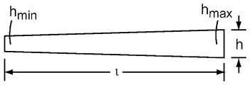
일부 실시예에서, 각각의 리브는 두께(t)에 의해 분리된 제1 및 제2 주 표면들을 포함하고, 리브의 종방향으로의 길이(l) 및 두께(t)와 길이(l) 각각에 수직한 방향으로의 높이(h)를 포함하며, 각각의 리브의 제1 및 제2 주 표면들은 실질적으로 평면형이다. 다양한 실시예에서, h는 2.5 mm 내지 8 mm이고, t는 0.5 mm 내지 2.5 mm이며, 그리고/또는 l은 15 mm 내지 45 mm이다. 일부 실시예에서, 각각의 리브의 높이(h)는 각각의 리브의 길이를 따라 변한다.In some embodiments, each rib comprises first and second major surfaces separated by a thickness t, and the length l in the longitudinal direction of the ribs and the length l of the ribs < RTI ID = 0.0 > And a height h in a vertical direction, wherein the first and second major surfaces of each rib are substantially planar. In various embodiments, h is from 2.5 mm to 8 mm, t is from 0.5 mm to 2.5 mm, and / or l is from 15 mm to 45 mm. In some embodiments, the height h of each rib varies along the length of each rib.
본 발명에 따른 안경 물품은, 사출 성형된 플라스틱이고 폴리카보네이트, 폴리에스테르, 폴리아미드 및 아세탈로 이루어진 군으로부터 선택된 재료로 제조될 수 있는 안경다리 피스를 포함할 수 있다.An eyeglass article according to the present invention may comprise an eyeglass leg piece that is injection molded plastic and may be made from a material selected from the group consisting of polycarbonate, polyester, polyamide and acetal.
일부 예시적인 실시예에서, 안경다리 피스는 접촉 부분을 포함하고, 안경 물품이 130 mm 내지 170 mm의 폭(W)을 갖는 사람의 머리 상에 사용을 위해 위치될 때 접촉 부분에 수직으로 가해지는 힘(F)은 50 g 내지 110 g이다. 일부 예시적인 실시예에서, 안경 물품이 150 mm 내지 180 mm의 폭(W)을 갖는 사람의 머리 상에 사용을 위해 위치될 때 F는 70 g 내지 110 g일 수 있다.In some exemplary embodiments, the eyeglass leg piece includes a contact portion, and when the eyeglass article is positioned for use on a person's head having a width (W) of 130 mm to 170 mm, The force (F) is from 50 g to 110 g. In some exemplary embodiments, F may be from 70 g to 110 g when the eyeglass article is placed for use on a person's head having a width W of between 150 mm and 180 mm.
일부 예시적인 실시예에서, 안경다리 피스는 접촉 부분을 추가로 포함하고, 안경 물품이 130 mm의 폭을 갖는 사람의 머리 상에 사용을 위해 위치될 때 제1 힘(F1)이 접촉 부분에 수직으로 가해지며, 안경 물품이 180 mm의 폭을 갖는 사람의 머리 상에 사용을 위해 위치될 때 제2 힘(F2)이 접촉 부분에 수직으로 가해지고, (F2 - F1) < 50 그램이다.In some exemplary embodiments, the eyeglass leg piece further comprises a contact portion, and when the eyeglass article is positioned for use on a person's head having a width of 130 mm, the first force F1 is perpendicular to the contact portion And the second force F2 is applied vertically to the contact portion when the eye article is positioned for use on a person's head having a width of 180 mm, and (F2 - F1) < 50 grams.
본 발명의 안경은 보안경, 고글, 선글라스, 미용 안경, 시력 교정 안경, 및/또는 당업계에 공지된 바와 같은 다른 안경 물품일 수 있다. 본 발명의 상기 요약은 본 발명의 각각의 개시된 실시예 또는 모든 구현예를 설명하고자 하는 것은 아니다. 하기 도면 및 상세한 설명이 예시적인 실시예를 더욱 구체적으로 예시한다. 2012년 3월 2일자로 출원되고 발명의 명칭이 "아치형 굴곡 부재를 구비한 안경(Eyewear Having an Arcuate Flexural Member)"인 미국 특허 출원 제13/410,944호는 굴곡 부분을 구비한 예시적인 안경 물품의 구조 및 구성을 다루고 있으며, 본 명세서에 참고로 포함된다.The glasses of the present invention may be safety goggles, goggles, sunglasses, cosmetic glasses, vision correction glasses, and / or other eyeglass articles as is known in the art. The above summary of the present invention is not intended to describe each disclosed embodiment or every implementation of the present invention. The following figures and detailed description illustrate the exemplary embodiments in more detail. U.S. Patent Application Serial No. 13 / 410,944, filed Mar. 2, 2012, entitled " Eyewear Having an Arcuate Flexural Member, " describes an exemplary eyeglass article having a curved portion Structures, and configurations, which are incorporated herein by reference.
본 발명은 첨부된 도면을 참조하여 추가로 설명될 것이고, 동일한 구조는 여러 도면 전체에 걸쳐 동일한 도면 부호로 참조된다.
도 1은 본 발명에 따른 안경 물품의 사시도.
도 2는 안경 물품이 더 양호하게 이해될 수 있는 몇 가지 기준면을 정의하는, 본 발명에 따른 안경 물품의 사시도.
도 3은 본 발명에 따른 예시적인 굴곡 부분을 갖는 안경 물품의 전방으로부터 후향으로 연장하는 안경다리 피스의 사시도.
도 4a 내지 도 4c는 본 발명에 따른 예시적인 안경다리 피스의 리브의 측면도.
도 5a 및 도 5b는 제1 및 제2 평면형 표면을 가진 리브를 포함하는, 본 발명에 따른 굴곡 부분을 갖는 예시적인 안경다리 피스의 단면도.
도 6은 제1 및 제2 만곡된 표면을 가진 리브를 포함하는, 본 발명에 따른 굴곡 부분을 갖는 예시적인 안경다리 피스의 단면도.
도 7은 굴곡되지 않은 상태의 곡률을 가진 굴곡 부분과 안경다리 피스를 갖는, 본 발명에 따른 안경 물품의 상부 사시도.
도 8은 4개의 종방향으로 배치된 리브를 포함하는 굴곡 부분을 갖는, 본 발명에 따른 안경 물품의 사시도.
도 9는 4개의 종방향으로 배치된 리브를 포함하는, 본 발명에 따른 굴곡 부분의 사시도.
도 10은 본 발명에 따른 굴곡 부분의 예시적인 실시예의 측면도.
도 11은 본 발명에 따른 굴곡 부분의 예시적인 실시예의 단면도.BRIEF DESCRIPTION OF THE DRAWINGS The invention will be further described with reference to the accompanying drawings, wherein like structure is referred to by like reference numerals throughout the several views.
1 is a perspective view of an eyeglass article according to the present invention;
2 is a perspective view of an eyeglass article according to the present invention, which defines several reference planes in which the eyeglass article can be better understood;
3 is a perspective view of a spectacle leg piece extending from the front to the back of an eyeglass article having an exemplary curved portion according to the present invention;
Figures 4A-4C are side views of ribs of an exemplary eyeglass leg piece according to the present invention.
5A and 5B are cross-sectional views of an exemplary eyeglass leg piece having a flexure according to the present invention, including ribs having first and second planar surfaces.
6 is a cross-sectional view of an exemplary eyeglass leg piece having a flexure according to the present invention, including ribs having first and second curved surfaces.
7 is a top perspective view of an eyeglass article according to the present invention having a curved portion with curvature in an unfolded state and a spectacle leg piece.
Fig. 8 is a perspective view of an eyeglass article according to the present invention having a curved portion including four longitudinally arranged ribs; Fig.
Figure 9 is a perspective view of a flexure according to the present invention, including four longitudinally arranged ribs;
10 is a side view of an exemplary embodiment of a flexure according to the present invention.
11 is a cross-sectional view of an exemplary embodiment of a flexure according to the present invention.
본 발명은 일정 범위의 머리 크기에 적합한 맞춤성과 편안함의 균형을 제공하는 특징부를 갖는 안경 물품을 제공한다. 안경 물품은 비교적 작은 머리 폭을 가진 사용자 상에 안경 물품을 유지하기 위해 안경다리 피스의 접촉 부분에 충분한 힘을 제공하는 동시에, 비교적 큰 머리 폭을 가진 사용자 상에 위치될 때 요구되는 편안함 범위 내의 힘을 제공한다. 예시적인 실시예에서, 안경 물품은 종래의 안경 물품에 비해 사용자의 머리 폭에 덜 의존적인 요구되는 수준의 힘을 안경다리 피스의 접촉 부분에 제공한다.The present invention provides an eyeglass article having a feature that provides a balance of fit and comfort for a range of head sizes. The eyeglass article provides sufficient force to the contact portion of the eyeglass leg piece to hold the eyeglass article on a user with a relatively small head width while providing a force within a required comfort range when positioned on a user having a relatively large head width . In an exemplary embodiment, the eyeglass article provides a required level of force to the contact portion of the eyeglass leg piece that is less dependent on the user ' s head width as compared to a conventional eyeglass article.
도 1은 안경 물품(100)의 제1 예시적인 실시예를 도시한다. 안경 물품(100)은 하나 이상의 렌즈(130) 또는 프레임을 포함하는 전통적인 안경 구성요소를 포함할 수 있다. 안경 물품(100)은, 제1 단부 부분(111), 접촉 부분(112) 및 굴곡 부분(120)을 각각 갖는 2개의 안경다리 피스(110)를 포함한다. 안경다리 피스(110)는 안경 물품(100)의 전방으로부터 후향으로 연장한다. 굴곡 부분(120)은 굴곡되지 않은 상태에 있을 때 곡률 반경을 갖는다. 굴곡 부분(120)은 사용자의 머리를 수용하도록 외향으로 굴곡되고, 적합한 머리 폭의 범위에 걸쳐 원하는 특성을 제공하도록 구성된다. 예시적인 실시예에서, 접촉 부분(112)은 특정 머리 폭을 수용할 때 굴곡 부분(120)이 받는 굴곡과 관계없이 실질적으로 일정한 배향으로 유지된다. 사용을 위해 위치될 때, 안경 물품(100)은 안경 물품(100)의 의도된 기능성을 제공하기 위해 대체로 사용자의 눈 또는 눈들의 전방에 위치된다. 하나 이상의 렌즈(130)는 사용자의 시야와 상호작용하거나, 외부 요소로부터 사용자의 눈 및 사용자의 안면의 부분을 실질적으로 차단한다.1 shows a first exemplary embodiment of an
예시적인 실시예에서, 안경다리 피스(110)의 제1 단부 부분(111)은 안경 물품(100)의 하나 이상의 렌즈(130), 프레임 또는 다른 적합한 특징부의 부착 부분(150)에 고정될 수 있다. 안경다리 피스(110)는 당업계에 공지된 임의의 적합한 수단에 의해 부착 부분(150)에 고정될 수 있다. 예를 들어, 안경다리 피스(110)는 개방 위치와 폐쇄 위치 사이의 다양한 위치에서 축을 중심으로 한 안경다리 피스(110)의 피봇 운동을 허용하는 힌지에 의해 회전가능하게 고정될 수 있다. 이는, 안경 물품(100)의 하나 이상의 렌즈(130), 프레임 또는 다른 적합한 특징부의 대응 특징부와 정합하고 당업계에 공지된 바와 같이 나사, 핀 또는 다른 체결구에 의해 회전 결합으로 고정되는 특징부를 포함하는 안경다리 피스(110)의 제1 단부 부분(111)에 의해 달성될 수 있다. 안경다리 피스(110)는 또한 예를 들어 스냅 맞춤(snap fit) 부착을 사용하여 부착될 수 있다. 다른 예시적인 실시예에서, 안경 물품(100)은 프레임을 포함하거나 포함하지 않을 수 있고, 안경다리 피스(110)는 하나 이상의 렌즈의 부착 지점에 부착될 수 있다.The
전술된 안경 물품(100)의 구성요소는 별도로 형성되고 후속하여 함께 결합되어 안경 물품을 형성할 수 있다. 예시적인 실시예에서, 하나 이상의 렌즈(130) 및 프레임은 예컨대 사출 성형, 이송 성형(transfer molding), 압축 성형 또는 당업계에 공지된 다른 기술에 의해 단일 피스로 일체로 형성된다. 다른 예시적인 실시예에서, 안경다리 피스(110)는 사출 성형, 이송 성형, 압축 성형 또는 당업계에 공지된 다른 기술에 의해 형성되고, 후속하여 렌즈 또는 프레임에 결합될 수 있다. 대안적으로, 다양한 부품 또는 전체 안경 물품(100)이 일체로 형성될 수 있다.The components of the above-described
굴곡 부분(120)은 안경다리 피스 및 굴곡 부분이 받을 수 있는 정상 굽힘 범위에 걸쳐 탄성 변형을 허용하도록 적합한 특성을 가진 재료로부터 형성될 수 있다. 예시적인 실시예에서, 안경다리 피스(110) 및/또는 굴곡 부분(120)은 미국 매사추세츠주 피츠필드 소재의 사빅 이노베이티브 플라스틱스(Sabic Innovative Plastics)로부터 입수가능한 상표명 XYLEX X8300을 가진 재료와 같이 폴리카보네이트 및 폴리에스테르의 자외선 안정화된 블렌드, 또는 사빅 이노베이티브 플라스틱스로부터 입수가능한 상표명 XENOY 5720을 가진 재료와 같은 폴리카보네이트 및 폴리부틸렌의 블렌드로부터 제조된다. 다른 예시적인 실시예에서, 안경다리 피스(110) 및/또는 굴곡 부분(120)은 사빅 이노베이티브 플라스틱스로부터 입수가능한 PC124R과 같은 폴리카보네이트, 또는 이.아이. 듀폰 드 네모아 앤드 컴퍼니(E.I. Du Pont De Nemours and Co.)로부터 입수가능한 D100 ST와 같은 아세탈로부터 제조된다. 다른 적합한 재료는 다른 폴리카보네이트, 폴리에스테르, 폴리아미드, 아세탈, 열가소성재, 당업계에 공지된 바와 같은 다른 적합한 재료, 및 그러한 재료들의 적합한 조합을 포함한다.The
예시적인 실시예에서, 안경다리 피스(110) 및 굴곡 부분(120)은 800 MPa 내지 2500 MPa의 굴곡 탄성계수를 가진 재료로 제조된다. 다양한 예시적인 실시예에서, 굴곡 탄성계수는 약 800 MPa 내지 1700 MPa 또는 약 1000 MPa 내지 약 1200 MPa일 수 있다.In an exemplary embodiment, the
본 발명에 따른 안경 물품의 소정 특징부는 안경 물품(100)에 관하여 정의되고 도 2에 도시된 3개의 기준면을 고려하여 이해될 수 있다. 안경 물품(100)이 사용을 위해 위치될 때와 같이 수평으로 위치된 상태에서, 그리고 안경의 전방으로서 지칭될 수 있는 렌즈의 외부면으로부터 안경 물품(100)을 볼 때, 정중-시상면(161)은 안경 물품(100)을 가상 좌반부 및 우반부로 양분한다. 횡단면(162)은 안경 물품(100)을 가상 상부 부분 및 하부 부분으로 분할한다. 횡단면(162)은, 안경다리 피스가 개방 위치와 폐쇄 위치 사이에서 이동함에 따라 그리고 사용자의 머리를 수용하기 위해 굴곡되지 않은 상태에서 편향된 상태로 이동함에 따라 안경다리 피스(110)에 의해 형성되는 회전면에 대체로 평행하다. 안경다리 피스(110)는 프레임 또는 렌즈에 안경다리 피스(110)를 결합시키는 힌지가 완전히 개방될 때 개방 위치에 있는 것으로 언급되고, 안경다리 피스(110)는 안경다리 피스(110)의 접촉 부분(112) 상에 또는 그에 의해 어떠한 하중도 가해지지 않도록 굴곡되지 않은 상태로 유지된다. 안경다리 피스(110)는 예를 들어 안경다리 피스(110)가 내향으로 접히도록 힌지가 완전히 폐쇄된 때 폐쇄 위치에 있는 것으로 언급된다. 전방면(163)은 정중-시상면 및 횡단면 둘 모두에 직교하고, 하나 이상의 렌즈(130)의 최전방 부분에 실질적으로 접한다.Certain features of the eyeglass article according to the present invention can be understood with reference to the three reference planes shown in Fig. 2 and defined with respect to the
도 2에 도시된 바와 같이, 접촉 부분(112)의 위치 및 안경다리 피스(110)의 대응하는 편향은 안경 물품(100)의 횡단면(162)에 실질적으로 평행하고 정중-시상면(161)에 수직이며 안경 물품(100)의 정중-시상면으로부터 접촉 부분을 분리하는 거리(d)에 의해 특징지어질 수 있다. 예를 들어, 안경다리 피스(110)가 개방 위치 및 굴곡되지 않은 위치에 있을 때, 제1 거리가 정중-시상면(161)으로부터 접촉 부분(112)을 분리한다. 안경다리 피스(110)가 예를 들어 가상선으로 도시된 바와 같이 사용자의 머리를 수용하도록 굴곡된 때, 제2 거리(d)가 정중-시상면(161)으로부터 접촉 부분(112)을 분리한다. 제2 거리(d)는 안경 물품(100)이 그 상에 위치되는 머리의 폭의 크기의 대략 절반일 수 있다. 안경다리 피스(110)가 굴곡될 때, 복원력이 굴곡을 받지 않는 위치로 안경다리 피스(110)를 복귀시키도록 작용한다. 주어진 편향에 대해 안경다리 피스(110)의 접촉 부분(112)에 가해지는 힘의 크기가 결정될 수 있고, 본 명세서에 추가로 설명되는 바와 같이 안경다리 피스 및 안경 물품의 기하학적 형상 및 재료에 관련된다.2, the position of the
도 3은 본 발명에 따른 굴곡 부분(120)의 예시적인 실시예를 갖는 안경 물품(100)의 전방으로부터 후향으로 연장하는 안경다리 피스(110)를 도시한다. 굴곡 부분(120)은 제1 단부(121) 및 제2 단부(122)와, 제1 및 제2 단부들(121, 122) 사이에 종방향으로 배치된 제1 및 제2 리브(125, 126)를 갖는다. 각각의 리브는 두께(t)에 의해 분리된 제1 및 제2 주 표면(S1, S2)을 갖고, 리브의 종방향으로의 길이(l) 및 두께(t)와 길이(l) 각각에 수직한 방향으로의 높이(h)를 포함한다. 다양한 실시예에서, l은 대략 10 mm 내지 75 mm 또는 15 mm 내지 45 mm일 수 있거나, 대략 30 mm일 수 있다.Figure 3 shows a
도 3에 도시된 예시적인 실시예에서, 제1 및 제2 리브(125, 126) 각각의 내주연부 에지는 제1 및 제2 리브(125, 126)의 부분들 사이에서 연장하는 슬롯(129)을 한정한다. 대안의 예시적인 실시예에서, 내주연부 에지는 복수의 슬롯, 홈 또는 다른 개구를 한정할 수 있거나, 제1 및 제2 리브는 예를 들어 연결된 내주연부 에지를 가짐으로써 리브의 길이를 따라 완전하게 또는 부분적으로 결합될 수 있다.3, the inner peripheral edge of each of the first and
리브(125, 126)의 두께 및 높이는 힘이 안경다리 피스(110)에 가해질 때 굴곡 부분(120)이 어떻게 굽혀지고 달리 반작용할지에 영향을 미칠 수 있다. 구체적으로, 리브(125, 126)의 두께 및 높이는 안경다리 피스(110)에 힘이 가해질 때 굴곡 부분(120)이 초기에 굽혀지는 위치, 및 힘이 굴곡 부분(120) 전체에 걸쳐 어떻게 분포되는지에 영향을 미칠 수 있다. 다양한 예시적인 실시예에서, 리브(125, 126)는 2 mm 내지 10 mm 또는 2.5 mm 내지 8 mm인 높이(h)를 가질 수 있다. 예시적인 실시예에서, 리브(125, 126) 중 하나 또는 둘 모두는 최소 높이와 최대 높이 사이에서 변하는 높이(h)를 가질 수 있다. 그러한 실시예에서, 굴곡 부분(120)은 초기 힘이 안경다리 피스에 가해질 때 리브의 최소 높이의 위치에서 또는 그 부근에서 굽혀지기 시작할 수 있다.The thickness and height of the
예시적인 실시예에서, 리브(125, 126) 중 하나 또는 둘 모두의 최소 높이(hmin)는 예를 들어 도 4a에 도시된 바와 같이 굴곡 부분(120)의 제1 및 제2 단부(121, 122)로부터 이격된 위치에서 형성된다. 다른 예시적인 실시예에서, 각각의 리브의 높이는 도 4b에 도시된 바와 같이 균일할 수 있거나, 예를 들어 도 4c에 도시된 바와 같이 각각의 리브의 길이에 걸쳐 제1 단부(121) 부근에서의 최대 높이(hmax)로부터 제2 단부(122) 부근에서의 최소 높이(hmin)까지 변할 수 있다.In an exemplary embodiment, the minimum height hmin of one or both of the
예시적인 실시예에서, 제1 리브(125)는 굴곡 부분이 굴곡되지 않은 상태에 있을 때 제2 리브(126)에 대해 각을 이루어 배치되어, 리브(125, 126)의 내부면 상의 주 표면인 제1 주 표면(S1)은 180° 미만의 각도(θ)를 형성한다. 예를 들어 안경 물품(100)이 사용자의 머리 상에 사용을 위해 위치될 수 있도록 안경다리 피스(110)가 굴곡된 때, 리브(125, 126)는 서로에 대해 회전되어 각도(θ)가 이하에서 더욱 상세히 논의되는 바와 같이 더 커지게 된다. 도 5a에 도시된 바와 같이, 예를 들어, 안경다리 피스(110)가 굴곡되지 않은 상태에 있을 때 각각의 리브(125, 126)의 내부 표면 상에 제1 평면형 표면(S1)에 의해 한정된 각도(θ1)는 안경다리 피스(110)가 굴곡된 때 각각의 리브(125, 126)의 제1 평면형 표면(S1)에 의해 한정된 각도(θ2)보다 작다. 편향된 상태에서, 각도(θ2)는 θ1보다 180°에 더 가까운 값을 가져서, 각각의 리브(125, 126)의 표면(S1)은 평행에 더 가깝다. 각각의 리브의 상대 회전 때문에, 굽힘축을 중심으로 한 단면의 면적 관성 모멘트(area moment of inertia)는 감소된다. 따라서, 안경다리 피스(110)의 편향의 한계 변화(marginal change)에 대해 더 적은 힘이 요구되고, 접촉 부분(112)에 가해지는 힘이 이하에서 더욱 상세히 설명되는 바와 같이 편향의 추가의 증가에 따라 일정하게 유지되거나 더욱 천천히 증가한다.In an exemplary embodiment, the
다른 예시적인 실시예에서, 제1 및 제2 리브(125, 126)는 도 5b에 도시된 바와 같이 굴곡 부분(120)이 굴곡되지 않은 상태에 있을 때 각각의 리브의 외부면 상의 주 표면인 제2 주 표면(S2)이 180° 미만의 각도(θ)를 형성하도록 각을 이루어 배치될 수 있다. 안경 물품(100)이 사용자의 머리 상에 사용을 위해 위치될 수 있도록 안경다리 피스(110)가 굴곡된 때, 제1 및 제2 리브(125, 126)는 회전되어 각도(θ)가 180° 또는 180° 미만의 각도를 향해 감소한다. 도 5b에 도시된 바와 같이, 예를 들어, 각각의 리브(125, 126)의 외부 표면 상의 제2 평면형 표면(S2)은 안경다리 피스(110)가 굴곡되지 않은 때 각도(θ3)를 한정하고, 이 각도는 안경다리 피스(110)가 굴곡된 때 각각의 리브(125, 126)의 제2 평면형 표면(S2)에 의해 한정된 각도(θ4)보다 작다. 편향된 상태에서, 각도(θ4)는 θ3보다 180°에 더 가까운 값을 가져서, 각각의 리브(125, 126)의 표면(S2)은 평행에 더 가깝다.In another exemplary embodiment, the first and
다른 예시적인 실시예에서, 제1 리브(125) 및/또는 제2 리브(126)는 제1 및 제2 주 표면(S1, S2) 중 하나 또는 둘 모두가 예를 들어 도 5a 및 도 5b에 도시된 바와 같이 안경 물품(100)의 횡단면(162)에 수직하지 않도록 각을 이루어 배치된다. 즉, 제1 및 제2 주 표면(S1, S2) 중 하나 또는 둘 모두는 안경 물품(100)의 횡단면(162)과 90° 각도를 형성하는 5° 내에 있지 않다. 안경 물품(100)이 사용자의 머리 상에 사용을 위해 위치될 수 있도록 안경다리 피스(110)가 굴곡된 때, 제1 및 제2 리브(125, 126)는 제1 및 제2 주 표면(S1, S2) 중 하나 또는 둘 모두가 안경 물품(100)의 횡단면(162)에 수직인 것에 더 가깝도록 회전한다.In another exemplary embodiment, the
예시적인 실시예에서, 도 5a 및 도 5b에 도시된 바와 같이, 제1 및 제2 리브(125, 126)는 각각 제1 및 제2 평면형 표면들(S1, S2) 사이에서 내주연부 에지(123)로부터 외주연부 에지(124)까지 감소하는 두께(t)를 갖는다. 일부 예시적인 실시예에서, 제1 및 제2 리브는 0.5 mm 내지 5 mm인, 임의의 특정 지점에서의 두께(t)를 가질 수 있다. 다른 실시예에서, 두께(t)는 0.5 내지 4 mm 또는 0.5 mm 내지 2.5 mm일 수 있다. 굴곡 부분은 리브의 두께가 증가됨에 따라 더 강성으로 되고, 더 작은 두께를 가진 리브를 구비한 굴곡 부분에 비해 특정 안경다리 분리에 대해 안경다리 피스의 접촉 부분에서 더 큰 힘을 유발할 수 있다.5A and 5B, the first and
일부 예시적인 실시예에서, 두께(t)는 예를 들어 외주연부 에지(124)에서의 약 0.5 mm의 두께(t)와 내주연부 에지(123)에서의 약 2.5 mm의 두께(t) 사이에서 리브의 높이를 따라 변할 수 있다. 다른 예시적인 실시예에서, 제1 및 제2 리브(125, 126)는 각각의 리브의 높이(h)에 걸쳐 일정한 두께(t), 또는 내주연부 에지(123)로부터 외주연부 에지(124)까지 증가하는 두께(t)를 갖는다.In some exemplary embodiments, the thickness t may be, for example, between a thickness t of about 0.5 mm at the outer
일부 예시적인 실시예에서, 내주연부 에지(123)에서의 두께(tmax)는 각각의 리브(125, 126)의 길이(l)를 따라 일정하게 유지될 수 있는 반면, 외주연부 에지(124)에서의 두께(tmin)는 길이(l)를 따라 변한다. 예시적인 실시예에서, 내주연부 에지(123)에서의 두께(tmax)는 길이(l)를 따라 대략 1.5 mm이고, 외주연부 에지(124)에서의 tmin은 각각의 단부에서 대략 1.0 mm로부터 굴곡 부분(320)의 제1 단부(321)에 가장 인접한 각각의 리브의 단부로부터 대략 10 mm의 길이(l)를 따른 위치에서 대략 0.5 mm까지 길이(l)를 따라 변한다.In some exemplary embodiments, the thickness tmax at the inner
도 6에 도시된 다른 예시적인 실시예에서, 제1 및 제2 리브(125, 126)는 제1 및 제2 만곡된 표면(S1, S2)을 나타낼 수 있다. 리브가 제1 및 제2 평면형 표면을 갖는 실시예와 유사하게, 리브의 두께는 일정할 수 있거나, 리브의 높이에 걸쳐 변할 수 있다. 제1 및 제2 리브(125, 126)는 각각의 내주연부 에지(123)로부터 각각의 외주연부 에지(124)까지 감소하는, 제1 및 제2 만곡된 표면들(S1, S2) 사이의 두께(t)를 각각 갖는다.In another exemplary embodiment shown in FIG. 6, the first and
다른 예시적인 실시예에서, 제1 및 제2 리브(125, 126)는 일정한 두께(t), 또는 내주연부 에지(123)로부터 외주연부 에지(124)까지 증가하는 두께(t)를 갖는다. 대안적으로, 제1 및 제2 리브(125, 126)의 내주연부 에지는 연결될 수 있고, 두께(t)는 제1 및 제2 리브의 각각의 외주연부 에지(124)와 내주연부 에지(123)의 연결 지점 사이에서 각각의 리브의 높이에 걸쳐 변할 수 있다.In another exemplary embodiment, the first and
각각의 리브(125, 126)의 만곡된 표면은 리브의 곡률 반경을 한정한다. 리브는 굴곡되지 않은 상태에 있을 때 서로에 대해 각을 이루어 배치되어, 리브는 특정 곡률 반경(R1)을 한정한다. 안경 물품이 사용자의 머리 상에 사용을 위해 위치된 때와 같이 안경다리 피스(110)에 힘이 가해진 때, 제1 및 제2 리브(125, 126)는 가상선으로 도시된 리브(125, 126)에 의해 지시되는 바와 같이 곡률 반경(R2)이 더 커지도록 서로에 대해 굴곡되고 그리고/또는 회전할 수 있다.The curved surface of each
도 7은 본 발명에 따른 안경다리 피스(110)를 갖는 안경 물품(100)의 예시적인 실시예를 도시한다. 안경다리 피스(110)는 굴곡되지 않은 상태에 있을 때 곡률을 나타내는 굴곡 부분(120)을 갖는다. 굴곡 부분(120)의 곡률은 곡률 반경에 의해 한정될 수 있다. 곡률 반경은 곡선 상의 일 지점에 접하는 원의 반경이고, 곡선 상에서 지점간에 변할 수 있다. 급격한 곡선이 일반적으로 더 큰 곡률 및 더 작은 곡률 반경을 갖는 것으로 언급되고, 완만한 곡선이 일반적으로 더 작은 곡률 및 더 큰 곡률 반경을 갖는 것으로 언급된다. 예를 들어 사용자의 머리를 수용하기 위해 안경다리 피스(110)가 편향될 때, 굴곡 부분(120)의 곡률 반경은 증가된다. 따라서, 굴곡 부분(120)의 예시적인 실시예의 곡률은 안경이 사용자의 머리 상에 사용을 위해 위치될 때보다 굴곡되지 않은 상태에서 더 크다.Figure 7 illustrates an exemplary embodiment of an
안경다리 피스(110)의 굴곡 부분(120)은 굴곡 부분(120)이 굴곡되지 않은 상태에 있을 때 곡률 반경(ρ)에 의해 특징지어진다. 예시적인 실시예에서, 굴곡되지 않은 상태에 있을 때 굴곡 부분(120)의 곡률 반경(ρ)은 80 mm 미만이다. 다른 실시예에서, 굴곡 부분(120)의 곡률 반경(ρ)은, 굴곡 부분(120)이 굴곡되지 않은 상태에 있을 때, 20 mm 내지 60 mm 또는 45 mm 내지 55 mm이다. 예시적인 실시예에서, 곡률 반경(ρ)은 굴곡 부분(120)의 길이를 따라 일정하거나 거의 일정하다. 예를 들어, 굴곡 부분(120)은 최대 곡률 반경(ρM) 및 최소 곡률 반경(ρm)을 가질 수 있고, 최대 곡률 반경의 크기는 최소 곡률 반경의 크기의 5 mm 내에 있을 수 있다. 예시적인 실시예에서, 안경다리 피스(110)의 곡률 반경은 안경다리 피스의 길이를 따라 소정 길이에 있는 특정 지점에서의 곡률 반경으로서 특징지어질 수 있다. 예를 들어, 예시적인 실시예에서, 안경다리 피스(110)의 길이를 따라 부착 부분(150) 또는 제1 단부 부분(111)으로부터 30 mm의 거리에서 굴곡 부분(120)의 곡률 반경(ρ)은 20 mm 내지 80 mm이다.The bending
전술된 바와 같은 곡률 반경을 갖는 굴곡 부분이 본 발명에 따른 안경 물품에 몇 가지 이점을 제공한다. 작은 곡률 반경을 나타내는 굴곡 부분은, 착용자의 머리 상에 위치될 때 곡률이 부족한 전통적인 안경다리 피스가 받게 되는 편향과 비교할 때, 동일한 착용자의 머리를 수용하기 위해 추가적인 편향을 겪어야 한다. 즉, 실질적으로 직선형인 안경다리 피스는 각각의 안경다리 피스의 접촉 부분이 사용자의 머리 상에 위치되도록 충분히 분리되기 전에 굽힘을 거의 또는 전혀 겪지 않지만, 도 7에 도시된 안경 물품(100)의 안경다리 피스(110), 및 특히 굴곡 부분(120)은 사용자의 머리를 수용하기 위해 상당한 편향을 겪어야 한다. 따라서, 그러한 굴곡 부분을 갖는 안경다리 피스(110)는 전통적인 안경에 비해 안경다리 피스들(110) 사이의 더 작은 분리를 갖고서 응력을 받는 상태로 된다. 사용자의 머리 상에 안경 물품(100)을 고정시키기에 충분한 힘이 더욱 가요성인 안경다리 피스에 의해서도 얻어질 수 있다. 더욱이, 굴곡 부분(120)이 굴곡되지 않은 상태에 있을 때 존재하는 곡률 반경은 굴곡 부분이 대부분의 사용자 머리 폭에 대응하는 적절한 편향 범위 내에서 원하는 대로 기능하는 것을 허용한다. 즉, 굴곡 부분(120)의 특정된 곡률은 안경다리 피스(110)의 접촉 부분(112)이 요구되는 수준의 힘을 특정 안경다리 분리에 가하는 것을 허용한다. 이들 및 다른 이점은 이하에서 설명된 본 발명에 따른 굴곡 부분을 갖는 안경다리 피스의 힘 변위 특성을 참조하여 더욱 완전히 이해될 것이다.A curved portion having a radius of curvature as described above provides several advantages over the eyeglass article according to the present invention. The bending portion exhibiting a small radius of curvature must undergo additional deflection in order to accommodate the same wearer's head as compared to the deflection that a conventional spectacle legpiece with insufficient curvature is subjected to when placed on the wearer's head. That is, the substantially straight spectacle leg piece will experience little or no bending before it is sufficiently separated to place the contact portion of each spectacle leg piece on the user's head, The
본 발명에 따른 굴곡 부분을 포함하는 안경 물품은 이전의 안경 물품에 비해 더 넓은 범위의 머리 크기에 걸쳐 안경다리 피스의 접촉 부분에 요구되는 힘을 제공할 수 있다. 성인 머리의 중요 부분은 각각의 귀의 정상 위치 바로 위에서 측정된, 130 mm 내지 170 mm의 폭을 갖는다. 또한, 본 발명자는 대략 40 그램 내지 140 그램 또는 대략 50 그램 내지 110 그램 또는 대략 80 그램의 힘이, 안경 물품이 부주의하게 위치로부터 떨어지지 않을 것이고 불편함을 유발할 정도로 너무 많은 힘을 가하지 않을 것이도록, 안정과 제한된 압력의 최적의 지각되는 균형을 제공하는 것으로 판단하였다. 따라서, 예시적인 안경 물품(100)은 130 mm 내지 170 mm의 폭을 갖는 사람의 머리 상에 사용을 위해 위치될 때 상기 요구되는 범위 내의 접촉 지점에서의 힘을 나타낸다. 즉, 안경다리 피스(110)의 접촉 부분(112)에서의 힘은 도 2를 참조하여 전술된 바와 같이 안경 물품(100)의 정중-시상면(161)으로부터 각각의 안경다리 피스(110)의 접촉 부분(112)을 분리하는 거리(d)가 65 mm 내지 85 mm일 때 요구되는 범위 내에 있다. 예시적인 실시예에서, 접촉 부분(112)에 수직으로 가해지는 힘은 안경 물품(100)이 130 mm 내지 170 mm의 폭을 갖는 사람의 머리 상에 사용을 위해 위치된 때 50 그램 내지 140 그램이다. 다른 예시적인 실시예에서, 힘은 50 그램 내지 110 그램이고, 안경 물품(100)이 150 mm 내지 180 mm의 폭을 갖는 사람의 머리 상에 사용을 위해 위치될 때 또는 d가 75 mm 내지 90 mm일 때, 70 그램 내지 110 그램일 수 있다.An eyeglass article comprising a curved portion according to the present invention can provide the required force on the contact portion of the eyeglass leg piece over a wider range of head sizes than the previous eyeglass article. The major part of the adult head has a width of 130 mm to 170 mm, measured just above the normal position of each ear. The inventors have also found that a force of from about 40 grams to about 140 grams, or about 50 grams to about 110 grams or about 80 grams of force is applied so that the eyeglass article will not inadvertently fall out of position and will not exert too much force to cause discomfort, To provide an optimal perceived balance of stability and limited pressure. Thus, the
안경다리 피스의 변위 대 접촉 부분에 가해지는 힘을 나타내는 곡선이 예를 들어 이하에서 설명되는 하기의 절차 1에 의해 다양한 안경다리 분리에서 힘을 측정함으로써 안경 물품에 대해 얻어질 수 있다. 이론에 의해 구애되지 않고서, 그러한 곡선의 기울기는 측정된 안경다리 피스의 가요성에 관련된다. 따라서, 더욱 가요성인 안경다리 피스는 일반적으로 편향의 작은 증가가 접촉 부분에 가해지는 힘의 상대적으로 큰 증가를 유발하는 강성 안경다리 피스에 비해 일정 범위의 편향에 걸쳐 덜 변하는 접촉 부분에서의 힘을 생성할 것이다. 예시적인 실시예에서, 안경다리 피스(110)의 접촉 부분(112)에 가해지는 힘은 130 mm 내지 180 mm의 안경다리 분리의 범위에 걸쳐 50 그램 이하만큼 변한다. 즉, 안경 물품(100)이 130 mm의 폭을 갖는 사람의 머리 상에 사용을 위해 위치될 때 제1 힘(F1)이 접촉 부분(112)에 가해지고, 안경 물품(100)이 180 mm의 폭을 갖는 사람의 머리 상에 사용을 위해 위치될 때 제2 힘(F2)이 접촉 부분(112)에 가해지며, F2와 F1 사이의 차이는 50 그램 이하이다. 다양한 다른 실시예에서, F2와 F1 사이의 차이는 30 그램 미만 또는 20 그램 미만일 수 있다. 반대로, 많은 종래의 설계는 130 mm 내지 180 mm의 안경다리 분리의 범위에 걸쳐 50 그램보다 상당히 크게 변하는 힘을 나타낸다.The curve representing the force applied to the displacer-contact portion of the spectacles leg piece can be obtained for the spectacles article by measuring the force at various spectacle leg separations, for example, by the following
안경다리 피스(110)의 접촉 부분(112)에서 최소로 요구되는 힘의 수준이 많은 전통적인 안경다리 피스의 것에 비해 더 높은 가요성을 갖는 재료로 구성되었음에도 불구하고 얻어질 수 있다. 그러한 결과는 굴곡되지 않은 상태에 있을 때 안경다리 피스(110) 및 굴곡 부분(120)에 의해 보여지는 고유의 곡률과, 본 명세서에서 설명되는 바와 같은 종방향으로 배치된 리브의 존재의 조합에 부분적으로 기인한다. 예시적인 실시예에서, 안경다리 피스(110)는 안경다리 분리가 80 mm를 넘기 전에도 편향을 겪는다. 그 결과, 접촉 부분(112)에서의 힘은 많은 종래의 안경 물품의 것보다 큰 가요성을 갖는 안경다리 피스(110)임에도 불구하고 안경다리 분리가 130 mm 초과일 때 50 그램 초과의 값에 도달한다. 또한, 굴곡 부분(120)의 고유의 곡률에 의해 용이하게 되는 비교적 가요성인 안경다리 피스(110) 때문에, 힘 수준은 안경다리 분리의 더 큰 범위를 통해 요구되는 수준에 더 가깝게 유지된다.Can be obtained despite the fact that the level of minimum required force at the
안경다리 피스(110)의 예시적인 실시예에 의해 보여지는 접촉 부분(112)에 가해지는 힘 수준은 또한 굴곡 부분(120)의 구조 및 구성에 기인한다. 이론에 의해 구애되지 않고서, 본 발명의 안경다리 피스(110)의 접촉 부분(112)에 가해지는 힘은 안경다리 분리와 관련 면적 관성 모멘트의 곱에 비례하는 것으로 특징지어질 수 있다. 면적 관성 모멘트는 안경다리 피스(110)의 종축에 수직한 축을 중심으로 하여, 그리고 당업계에 공지된 바와 같은 굽힘면 내에서 계산된다. 편향이 증가함에 따라, 접촉 부분(112)에서의 힘이 증가하고, 편향이 감소함에 따라 접촉 부분(112)에서의 힘이 감소한다. 마찬가지로, 안경다리 피스(110)의 단면의 면적 관성 모멘트가 증가함에 따라, 접촉 부분(112)에서의 힘이 증가하고, 면적 관성 모멘트가 감소함에 따라, 접촉 부분(112)에서의 힘이 감소한다.The force level applied to the
종래의 안경다리 피스의 면적 관성 모멘트는 접촉 부분에 가해지는 힘이 편향에 대체로 비례하도록 편향될 때 실질적으로 일정하게 유지되는 것으로 여겨진다. 그러나, 굴곡 부분(120)의 예시적인 실시예에서, 특정 단면 위치의 면적 관성 모멘트는 안경다리 피스가 사용자의 머리를 수용하기 위해 굴곡됨에 따라 변한다. 전술된 바와 같이, 제1 및 제2 리브(125, 126)는 안경다리 피스(110)가 편향됨에 따라 서로에 대해 회전한다. 그 결과, 굴곡 부분(120)의 특정 단면에서의 면적 관성 모멘트는 안경다리 피스(110)가 편향됨에 따라 변한다. 예를 들어, 안경 물품이 제1 폭을 가진 머리 상에 사용을 위해 위치될 때, 단면의 면적 관성 모멘트는 안경 물품이 제1 폭보다 큰 제2 폭을 가진 머리 상에 사용을 위해 위치될 때보다 크다. 따라서, 안경다리 피스의 단면의 면적 관성 모멘트는 굴곡 부분이 추가적인 굴곡을 겪음에 따라 감소한다. 이러한 방식으로, 안경다리 피스(110)가 증가하는 머리 폭을 수용하기 위해 편향되거나 굴곡됨에 따라 안경다리 피스(110)의 접촉 부분(112)에 가해지는 힘의 증가를 나타내기보다는, 면적 관성 모멘트가 감소된다. 안경다리 피스(110)의 접촉 부분(112)에 가해진 힘은 실질적으로 일정하게 유지되거나, 안경다리 피스(110)의 편향의 범위에 걸쳐 그리고 그에 따라 사용자 머리 크기의 범위에 걸쳐 더 작은 변동을 나타낸다.It is believed that the area moment of inertia of a conventional spectacle leg piece remains substantially constant when the force applied to the contact portion is biased to be substantially proportional to the deflection. However, in an exemplary embodiment of the
전술된 특징 및 특성에 더하여, 안경 물품의 맞춤성은 사용자의 머리 둘레의 안경다리 피스의 위치설정, 및 특히 안경다리 피스의 접촉 부분이 사용자의 머리와 접촉하는 위치 및 배향에 부분적으로 의존할 수 있다. 본 발명에 따른 안경다리 피스의 예시적인 실시예에서, 사용자에 가해지는 압력이 최소화되도록 사용자의 머리와 접촉하는 면적을 최대화하기 위해 접촉 부분은 실질적으로 평면형 표면을 가질 수 있다. 편안함은 예를 들어 접촉 부분의 에지만이 사용자의 머리와 접촉하는 경우 감소될 수 있다. 따라서, 본 발명에 따른 예시적인 안경다리 피스의 접촉 부분은 머리 크기의 요구되는 범위에 대응하는 안경다리 분리의 범위 내의 임의의 위치에서 실질적으로 수직 배향으로 유지되고, 위에서 정의된 횡단면에 실질적으로 평행한 평면 내에서 유지된다. 즉, 본 발명에 따른 예시적인 안경다리 피스는 안경다리 피스의 종축을 중심으로 한 회전 또는 굴곡되지 않은 상태에서 안경다리 피스에 의해 한정된 평면 밖으로의 회전에 저항한다.In addition to the features and characteristics described above, the fit of the eyeglass article may depend in part on the positioning of the eyeglass legs around the user's head, and in particular the position and orientation at which the contact portion of the eyeglass legs contacts the user's head . In an exemplary embodiment of a spectacle leg piece according to the present invention, the contact portion may have a substantially planar surface to maximize the area of contact with the user ' s head such that the pressure applied to the user is minimized. The comfort can be reduced, for example, if only the edge of the contact portion is in contact with the user ' s head. Thus, the contact portion of an exemplary eyeglass leg piece according to the present invention is maintained in a substantially vertical orientation at any position within the range of eyeglass leg separation corresponding to the desired range of head size, and is substantially parallel to the cross section defined above And is maintained in one plane. That is, an exemplary spectacle leg piece according to the present invention resists rotation out of the plane defined by the spectacle leg piece in a state of no rotation or unfolding about the longitudinal axis of the spectacle leg piece.
본 발명에 따른 안경 물품(200)의 예시적인 실시예가 도 8 및 도 9에 도시된다. 안경 물품(200)은 하나 이상의 렌즈(230) 또는 프레임을 포함하는 전통적인 안경 구성요소를 포함할 수 있다. 안경 물품(200)은, 굴곡 부분(220) 및 접촉 부분(212)을 각각 갖는 2개의 안경다리 피스(210)를 포함한다. 굴곡 부분(220)은 제1 단부(221) 및 제2 단부(222)를 갖고, 종방향으로 배치된 제1 및 제2 리브(225, 226) 및 종방향으로 배치된 제3 및 제4 리브(227, 228)를 포함한다. 각각의 리브는 각각의 리브의 내부 및 외부 표면 상에 각각 제1 및 제2 주 표면(S1, S2)과, 각각의 리브의 종방향으로의 길이에 수직한 방향으로 높이(h)를 갖는다. 또한, 굴곡 부분(220)은 안경 물품의 정중-시상면에 평행한 방향으로 최대 높이(H)를 나타낸다. 예시적인 실시예에서, 최대 높이(H)는 굴곡 부분(220)의 단부(221) 부근에서 안경다리 피스(210)를 따른 위치에서 형성된다. 안경 물품(200)의 다양한 특징 및 특성이, 안경 물품(100)을 참조하여 전술되고 그리고 도 2에 도시된 바와 같이 배향된 3개의 기준면에 대해 한정될 수 있다.An exemplary embodiment of an
예시적인 실시예에서, 리브(225)는 리브(226)에 대해 각을 이루어 배치되고, 리브(227)는 리브(228)에 대해 각을 이루어 배치되어, 각각 리브(225, 226) 및 리브(227, 228)의 내부면 상의 제1 주 표면(S1)은 180° 미만의 각도를 형성한다. 안경 물품(200)이 사용자의 머리 상에 사용을 위해 위치될 수 있도록 안경다리 피스(210)가 굴곡된 때, 리브(225, 226, 227, 228)는 각각 리브(225, 226) 및 리브(227, 228)의 제1 주 표면(S1)이 굴곡되지 않은 상태에 있을 때보다 180°에 더 가까운 각도를 형성하도록 회전한다. 다른 예시적인 실시예에서, 리브(225)는 리브(226)에 대해 각을 이루어 배치되고, 리브(227)는 리브(228)에 대해 각을 이루어 배치되어, 각각 리브(225, 226) 및 리브(227, 228)의 외부면 상의 제2 주 표면(S2)은 180° 미만의 각도를 형성한다. 안경 물품(200)이 사용자의 머리 상에 사용을 위해 위치될 수 있도록 안경다리 피스(210)가 굴곡된 때, 리브(225, 226, 227, 228)는 각각 리브(225, 226) 및 리브(227, 228)의 제2 주 표면(S2)이 굴곡되지 않은 상태에 있을 때보다 180°에 더 가까운 각도를 형성하도록 회전한다. 다른 예시적인 실시예에서, 리브(225, 226, 227, 228) 중 하나 이상은 제1 및 제2 주 표면(S1, S2) 중 하나 또는 둘 모두가 안경 물품(200)의 횡단면에 수직하지 않도록 배치된다. 즉, 제1 및 제2 주 표면(S1, S2) 중 하나 또는 둘 모두는 안경 물품(200)의 횡단면과 90° 각도를 형성하는 5° 내에 있지 않다. 안경 물품(200)이 사용자의 머리 상에 사용을 위해 위치될 수 있도록 안경다리 피스(210)가 굴곡된 때, 리브(225, 226, 227, 228)는 각각 리브(225, 226) 및 리브(227, 228)의 제1 및 제2 주 표면(S1 또는 S2) 중 하나 또는 둘 모두가 안경 물품(200)의 횡단면에 수직 관계에 있는 것에 더 가깝도록 회전한다.In an exemplary embodiment,
도 9에 도시된 예시적인 실시예에서, 슬롯(229)은 각각의 리브 사이에 한정된다. 대안의 예시적인 실시예에서, 내주연부 에지는 복수의 슬롯, 홈 또는 다른 개구를 한정할 수 있고, 제1 및 제2 리브는 예를 들어 연결된 내주연부 에지를 가짐으로써 리브의 길이를 따라 완전하게 또는 부분적으로 결합될 수 있다.In the exemplary embodiment shown in FIG. 9, a
예시적인 실시예에서, 종방향으로 배치된 리브(225, 226, 227, 228)는 안경 물품(100)을 참조하여 전술된 리브와 실질적으로 동일하고, 안경다리 분리의 범위에 걸쳐 접촉 부분(212)에서 요구되는 힘을 생성하도록 유사한 방식으로 기능한다. 4개의 종방향으로 배치된 리브를 갖는 굴곡 부분은 본 명세서에서 설명된 바와 같이 단일 쌍의 리브의 기능성 및 이점을 갖는 동시에, 안경다리 피스(210)가 사용자의 머리를 수용하기 위해 편향됨에 따라 요구되는 배향, 예를 들어 실질적으로 수직인 배향으로 접촉 부분(212)이 유지될 가능성이 더 높도록 추가의 비틀림 안정성을 제공한다. 예시적인 실시예에서, 굴곡 부분(220)은 종축을 중심으로 32 N-mm/라디안 초과 또는 56 N-mm/라디안 초과의 비틀림 강성(K)을 갖는다. 비틀림 강성은 비틀림 각도에 대한 가해진 비틀림 모멘트의 비로서 정의될 수 있고, 비틀림 회전에 대한 저항을 특징짓는 데 사용될 수 있다. 더 큰 비틀림 강성을 갖는 굴곡 부분이 종축을 중심으로 회전을 겪는 데 더 큰 힘을 필요로 하고, 따라서 더 큰 비틀림 강성을 갖는 굴곡 부분을 가진 안경다리 피스는 안경다리 피스가 사용자의 머리를 수용하기 위해 편향됨에 따라 요구되는 배향으로 유지될 가능성이 더 높다.In an exemplary embodiment, the longitudinally arranged
본 발명의 다양한 실시예에서, 굴곡 부분은 15 mm 초과 또는 20 mm 초과 또는 24 mm 초과인 최대 높이(H)를 갖는다. 위에서 특정된 바와 같은 최대 높이(H)를 갖는 굴곡 부분은 4개의 종방향 리브를 포함할 수 있거나, 비교적 더 큰 높이의 2개의 종방향으로 배치된 리브를 포함할 수 있다. 최대 높이(H)가 증가함에 따라, 비틀림 강성은 증가한다. 따라서, 위에서 특정된 바와 같은 최대 높이(H)를 갖는 굴곡 부분은 사용자의 머리를 수용하기 위해 안경다리 피스가 편향됨에 따라 요구되는 배향으로 유지될 가능성이 더 높다.In various embodiments of the present invention, the bending portion has a maximum height H greater than 15 mm or greater than 20 mm or greater than 24 mm. The flexure portion having the maximum height H as specified above may include four longitudinal ribs or may include two longitudinally arranged ribs of relatively greater height. As the maximum height H increases, the torsional stiffness increases. Thus, the bending portion with the maximum height H as specified above is more likely to remain in the required orientation as the eyeglass leg piece is deflected to accommodate the user's head.
다양한 실시예에서, 본 발명에 따른 안경 물품은 본 명세서에서 설명된 이점 및 특성을 얻는 동시에 2개, 3개, 4개 또는 그보다 많은 종방향으로 배치된 리브를 포함할 수 있다. 예시적인 실시예에서, 안경 물품(200)은 2개 초과의 종방향으로 배치된 리브를 포함하고, 각각의 리브는 두께(t)에 의해 분리된 제1 및 제2 주 표면을 포함하며, 각각의 리브의 제1 주 표면은 안경 물품을 가상 상반부 및 하반부로 양분하는 횡단면에 대해 수직하지 않다.In various embodiments, a spectacles article in accordance with the present invention may include two, three, four, or more longitudinally arranged ribs while attaining the advantages and features described herein. In an exemplary embodiment, the
전술된 특징부를 갖는 예시적인 안경다리 피스(210)는 접촉 부분(212)이 안경다리 분리의 특정 범위 내의 임의의 위치에서 실질적으로 수직인 배향으로 유지되도록 충분한 비틀림 안정성을 제공하여, 안경다리 피스의 종축을 중심으로 한 회전에 저항한다.An exemplary
본 명세서에서 설명된 다양한 특징부 및 특징부들의 조합을 갖는 안경 물품은 몇 가지 이점을 제공한다. 많은 종래 기술의 설계는 안경다리 피스가 편향됨에 따라 안경다리 피스에 의해 가해진 힘이 비교적 큰 기울기로 선형으로 증가하도록, 그리고 안경 물품이 다른 폭을 갖는 머리 상에 위치될 때 상당히 상이한 수준의 힘이 안경다리 피스에 의해 가해지도록, 선형 힘-변위 응답을 나타내는 것으로 보인다. 따라서, 단일 안경 물품은 상이한 머리 폭을 갖는 개인에 의해 사용될 때 상이한 수준의 편안함을 제공할 수 있다. 많은 종래 설계와 반대로, 본 발명에 따른 안경 물품은 예상되는 안경다리 분리의 범위의 일부에 걸쳐 비-선형 힘-변위 응답 또는 비교적 작은 기울기를 갖는 선형 힘-변위 응답을 나타내는 안경 물품을 제공함으로써 머리 폭의 범위에 걸쳐 맞춤성과 편안함의 균형을 제공한다. 굴곡 부분이 굴곡됨에 따라 변하는 면적 관성 모멘트를 나타내는 굴곡 부분 및 고유의 곡률을 갖는 굴곡 부분의 조합에 기인하여, 단일 안경 물품이 비교적 큰 머리 폭을 가진 사용자뿐만 아니라 비교적 작은 머리 폭을 가진 사용자에 요구되는 힘 수준을 제공할 수 있다. 또한, 상이한 머리 폭을 가진 사용자에게 상이한 크기의 안경 물품을 제공하는 것과 관련된 비용이 감소되고, 복잡하거나 이동 부품을 포함하는 설계와 관련된 제조 비용이 최소화된다.An eyeglass article having a combination of various features and features described herein provides several advantages. Many prior art designs are designed so that the force applied by the eyeglass leg piece linearly increases with a relatively large slope as the eyeglass leg piece is deflected, and a very different level of force when the eyeglass article is placed on a head with a different width It appears to represent a linear force-displacement response so that it is imposed by the spectacle leg piece. Thus, a single eye article can provide different levels of comfort when used by individuals having different hair widths. In contrast to many conventional designs, the eyeglass article according to the present invention provides an eyeglass article that exhibits a linear force-displacement response with a non-linear force-displacement response or a relatively small gradient over a portion of the expected range of eye- Provides a balance of fit and comfort over a range of widths. Due to the combination of the curved portion exhibiting the area moment of inertia and the curved portion having the inherent curvature that change as the curved portion flexes, a single eyeglass article requires a user with a relatively large head width as well as a user with a relatively large head width ≪ / RTI > In addition, the costs associated with providing different size eyewear items to users with different hair widths are reduced, and manufacturing costs associated with designs involving complex or moving parts are minimized.
예Yes
본 발명의 특성, 작동 및 이점이 하기 상세한 비제한적인 예에 관해서 추가로 설명될 것이다. 이들 예는 다양한 특정하고 바람직한 실시예 및 기술을 추가로 예시하기 위해 제공된다. 그러나, 본 발명의 범주 내에 있는 상태에서 많은 변형 및 수정이 이루어질 수 있음을 이해하여야 한다.The nature, operation, and advantages of the present invention will be further described with respect to the following detailed non-limiting examples. These examples are provided to further illustrate various specific and preferred embodiments and techniques. It should be understood, however, that many modifications and variations may be made while remaining within the scope of the present invention.
절차 1: 힘-편향 측정Procedure 1: Force-deflection measurement
안경다리 피스의 편향 대 접촉 부분에 가해진 힘의 측정은 안경 물품이 일정 범위의 머리 크기에 걸쳐 나타낼 수 있는 편안함의 지시를 제공한다. 안경다리 분리로서 지시되는 값은 머리 폭과 유사하고, 안경 물품(100)의 정중-시상면(161)으로부터 안경다리 피스(110)의 접촉 부분(112)을 분리하는, 전술된 거리(d)의 대략 2배이다. 각각의 안경다리 분리에 대해 얻어진 힘은 안경 물품이 사람의 머리 상에 사용을 위해 위치될 때 접촉 부분에 가해질 힘과 유사하다.The measurement of the force exerted on the deflection-to-contact portion of the spectacle leg piece provides an indication of comfort that the spectacle article can exhibit over a range of head sizes. The value indicated as eyeglass leg separation is similar to the head width and is the distance d described above that separates the
힘 대 편향 데이터를, 미국 뉴욕주 롱 아일랜드 소재의 마크-10 코프.(Mark-10 Corp.)로부터 입수가능한 2개의 마크-10 MG05 힘 게이지 및 렌즈 지지체를 포함하는 주문제작 고정구를 사용하여 얻었다. 각각의 힘 게이지를, 구동 나사가 회전됨에 따라 각각의 힘 게이지의 로드 포스트(load post)가 고정구의 중심점으로부터 동일 거리로 이동하도록 병진 운동 스테이지 상에 장착하였고 구동 나사에 의해 위치설정 가능하였다. 즉, 각각의 로드 포스트는 안경 물품을 가상 좌반부 및 우반부로 분할하는 정중-시상면으로부터 대략 등거리에 있었다. 각각의 힘 게이지의 로드 포스트들 사이의 거리를 지시하도록 선형 스케일을 제공하였다. 렌즈가 렌즈 지지체에 클램핑되고 각각의 안경다리 피스가 각자의 로드 포스트의 외측에 위치된 상태로 샘플을 고정구 상에 배치하였다. 로드 포스트들 사이의 초기 거리는 80 mm였고, 로드 포스트는 샘플의 렌즈의 전방으로부터 대략 110 mm 거리에서 안경다리 피스와 접촉하였다. 각각의 로드 포스트 사이의 분리 거리, 및 그에 따른 각각의 안경다리 피스의 접촉 부분은 동일 크기의 머리 폭에 대응하는 것으로 언급될 수 있다. 힘 측정치를 130 mm에서 180 mm까지의 로드 포스트 간격 사이에서 10 mm 증분으로 각각의 로드 셀(load cell)로부터 기록하였다. 안경다리 피스를 로드 포스트에 클램핑 또는 고정시키지 않았고, 로드 포스트들 사이의 분리 거리가 증가됨에 따라 로드 포스트에 대해 자유롭게 이동하게 하였다.Force versus deflection data was obtained using a custom made fastener comprising two Mark-10 MG05 force gauges and a lens support, available from Mark-10 Corp. of Long Island, NY, USA. Each force gauge was mounted on a translating stage so that the load post of each force gauge moved the same distance from the center point of the fixture as the drive screw was rotated and was positionable by a drive screw. That is, each load post was approximately equidistant from the median-sagittal plane that splits the eyeglass article into virtual left and right halves. A linear scale was provided to indicate the distance between the load posts of each force gauge. The lens was clamped to the lens support and the sample was placed on the fixture with each eye piece positioned on the outside of the respective load posts. The initial distance between the rod posts was 80 mm, and the rod posts contacted the glasses leg piece at a distance of about 110 mm from the front of the lens of the sample. The separation distance between each load post, and consequently the contact portion of each spectacle leg piece, can be referred to as corresponding to a head width of the same size. Force measurements were recorded from each load cell in 10 mm increments between load post spacings from 130 mm to 180 mm. The eyeglass leg piece was not clamped or secured to the rod post and allowed to move freely relative to the rod post as the separation distance between the rod posts increased.
예 1 내지 예 5Examples 1 to 5
예 1 내지 예 5를 절차 1에 따라 측정하였다. 예 1의 샘플은 쓰리엠 컴퍼니(3M Company)로부터 입수가능한 VIRTUA® # 70-0715-3942-6 보안경이었다. 예 2의 샘플은 유벡스 세이프티 그룹(Uvex Safety Group)으로부터 입수가능한 GRAVITY ZERO # 9191.265 보안경이었다. 예 3의 샘플은 피라멕스(Pyramex)로부터 입수가능한 MONTEGO # SB5310S 보안경이었다. 샘플 4는 본 발명에 따른 안경 물품이었고, 사빅 이노베이티브 플라스틱스로부터 입수가능한 XYLEX 8300으로서 지칭되는 재료로 구성하였다. 예 5의 샘플은 본 발명에 따른 안경 물품이었고, 듀폰으로부터 입수가능한 D100 ST로서 지칭되는 재료로 구성하였다.Examples 1 to 5 were measured according to
예 4 및 예 5의 샘플은 도 7, 도 10 및 도 11에 도시된 예시적인 실시예와 일치하는 치수를 가졌다. 도 7은 본 발명에 따른 예시적인 안경다리 피스(110)의 평면도의 스케일 도면을 제공한다. 굴곡 부분은 대략 50 mm의 곡률 반경을 갖는다. 도 10은 본 발명에 따른 안경 물품의 측면도를 제공한다. 리브(325, 326, 327, 328) 각각은 대략 5 mm의 최대 높이(hmax) 및 대략 2.5 mm의 최소 높이(hmin)를 갖는다. 각각의 리브의 길이(l)는 대략 30 mm이다. 슬롯(329)은 대략 1.5 mm의 최대 폭(Wmax) 및 대략 0.8 mm의 최소 폭(Wmin)을 갖는다.The samples of Examples 4 and 5 had dimensions consistent with the exemplary embodiments shown in Figs. 7, 10 and 11. Figure 7 provides a scale view of a top view of an exemplary
도 11은 도 10의 선 11-11에서의 단면도를 제공한다. 각각의 리브는 내주연부 에지(323)에서의 최대 두께(tmax)로부터 외주연부 에지(324)에서의 최소 두께(tmin)까지 감소하는 두께를 갖는다. 내주연부 에지(323)에서의 두께(tmax)는 각각의 리브의 길이(l)를 따라 대략 1.5 mm이다. 각각의 리브의 외주연부 에지(324)에서의 두께(tmin)는 리브의 길이를 따라, 각각의 단부에서 대략 1.0 mm의 두께로부터 굴곡 부분(320)의 제1 단부(321)에 가장 인접한 각각의 리브의 단부로부터 대략 10 mm의 길이(l)를 따른 거리에서 대략 0.5 mm의 두께까지 변한다. 리브(125, 126)의 길이의 중간점에서 각각의 리브(125, 126)의 내부 표면(S1)에 의해 형성된 각도(θ)는 대략 155°이다.Figure 11 provides a cross-sectional view at line 11-11 of Figure 10; Each rib has a thickness decreasing from the maximum thickness tmax at the inner

표 1은 예 1 내지 예 5에 대해 절차 1에 따라 접촉 부분에서 측정된 힘을 그램으로 나타낸다. 예 1 내지 예 3의 샘플은 본 발명에 따른 종방향으로 배치된 리브를 갖는 굴곡 부분이 없었고, 일정 범위의 안경다리 분리에 걸쳐 요구되는 힘 수준, 예를 들어 50 내지 140 그램을 제공하지 못했다.Table 1 shows the force in grams measured at the contact area according to
예 1은 130 mm 내지 180 mm의 정상 머리 크기의 전체 범위에 걸쳐서 요구되는 힘 수준을 제공하는 데 실패하였다. 예 1의 샘플의 안경다리 분리가 130 mm였을 때, 접촉 부분에 가해지는 힘은 20 그램 미만이었다. 그러한 값은 요구되는 범위 미만이고, 대략 130 mm의 머리 폭을 가진 사용자는 안경이 불안정한 것으로 지각할 수 있다. 유사하게, 예 1의 샘플의 안경다리 분리가 180 mm에 접근한 때, 접촉 부분에 가해지는 힘은 150 그램을 초과하였다. 그 결과, 안경 물품은 사용자의 머리에 과도한 압력을 유발할 가능성이 있고, 불편함을 초래한다. 결국, 예 1의 샘플의 접촉 부분에 가해지는 힘은 예를 들어 예 4 또는 예 5의 샘플에 비해 좁은 범위의 머리 크기에 대해서만 요구되는 수준 내에 포함된다.Example 1 failed to provide the required force level over the entire range of normal head sizes from 130 mm to 180 mm. When the spectacle leg separation of the sample of Example 1 was 130 mm, the force applied to the contact portion was less than 20 grams. Such a value is below the required range, and a user with a hair width of approximately 130 mm may perceive that the glasses are unstable. Similarly, when the spectacle leg separation of the sample of Example 1 approached 180 mm, the force exerted on the contact portion exceeded 150 grams. As a result, the eyeglass article may cause excessive pressure on the user's head, resulting in inconvenience. As a result, the force exerted on the contact portion of the sample of Example 1 is contained within the required level only for a narrow range of head size, compared to the sample of Example 4 or Example 5, for example.
예 2의 샘플은 마찬가지로 130 mm 내지 180 mm의 정상 머리 크기의 전체 범위에 걸쳐 요구되는 힘 수준을 제공하는 데 실패하였다. 150 mm의 안경다리 분리에서, 접촉 부분에 가해지는 힘은 100 그램을 초과하였다. 180 mm의 안경다리 분리에서, 접촉 지점에 가해지는 힘은 175 그램이었다. 따라서, 그러한 안경이 180 mm의 머리 폭을 가진 사용자에 의해 착용될 때 불편함이 초래될 가능성이 있다.The sample of Example 2 similarly failed to provide the required force level over the entire range of normal head sizes from 130 mm to 180 mm. In 150 mm spectacle leg separation, the force exerted on the contact area exceeded 100 grams. In 180 mm spectacle leg separation, the force applied to the point of contact was 175 grams. Thus, there is a possibility that such glasses are inconvenient when worn by a user with a head width of 180 mm.
예 3의 샘플의 접촉 부분에 가해지는 힘은 105.5 그램 내지 129.5 그램에서만 변하지만, 130 mm 내지 180 mm의 안경다리 분리의 범위 내에서 요구되는 힘의 수준을 지속적으로 초과한다. 따라서, 접촉 부분에서의 힘은 최적의 안정 수준을 제공하는 데 필요한 것보다 클 가능성이 있고, 사용자에게 불편함을 초래할 수 있다.The force exerted on the contact portion of the sample of Example 3 varies only from 105.5 grams to 129.5 grams, but it continually exceeds the level of force required within the range of 130 to 180 mm of spectacle leg separation. Therefore, the force at the contact portion is likely to be greater than is necessary to provide an optimal level of stability, and may cause discomfort to the user.
예 4 및 예 5의 샘플은 일정 범위의 안경다리 분리에 걸쳐 바람직한 힘 수준을 제공하였다. 본 발명에 따른 특징부를 갖는 예 4의 샘플은 130 mm의 안경다리 분리에서 대략 50 그램의 힘 수준을 나타내었다. 그러한 힘은 요구되는 범위 내이고, 편안함과 맞춤성의 안정의 지각되는 균형을 제공할 것이다. 안경다리 분리가 최대 180 mm까지의 값으로 증가됨에 따라, 힘은 110 그램 미만으로 유지되었다. 예 5의 샘플에서, 접촉 부분에 가해지는 힘은 130 mm의 안경다리 분리에서 대략 73 그램이었고, 180 mm의 안경다리 분리까지 거의 일정하게 유지되었다. 예 1 및 예 2의 전통적인 안경과 대조적으로, 예 5의 샘플은 안경다리 분리가 180 mm에 접근한 때에도 불편할 가능성이 있는 접촉 부분에서의 힘의 수준을 가하지 않았다.The samples of Examples 4 and 5 provided the desired strength levels over a range of spectacle leg separation. The sample of Example 4 with the features according to the present invention exhibited a force level of approximately 50 grams in a 130 mm spectacle leg separation. Such a force is within the required range and will provide a perceived balance of comfort and fit stability. As the spectacle leg separation increased to values up to 180 mm, the force was kept below 110 grams. In the sample of Example 5, the force exerted on the contact portion was approximately 73 grams at 130 mm spectacle leg separation, and remained nearly constant until 180 mm spectacle leg separation. In contrast to the traditional glasses of Examples 1 and 2, the sample of Example 5 did not add a level of force at the contact portion, which may be uncomfortable even when the eyeglass leg separation approaches 180 mm.
결국, 예 4 및 예 5의 샘플은, 비교적 작은 머리 폭에 대해 안정한 맞춤성을 제공하기에 충분한 힘이 발생되는 동시에 비교적 큰 폭을 가진 머리 상에 위치된 때 편안한 범위로 최대 힘이 제한되도록, 일정 범위의 안경다리 분리에 걸쳐 바람직한 힘 수준을 제공하였다.As a result, the samples of Examples 4 and 5 exhibit sufficient strength to provide a stable fit for a relatively small head width, while at the same time to limit the maximum force to a comfortable range when placed on a head having a relatively large width, Providing a desirable level of strength over a range of spectacle leg separation.
절차 2: 비틀림 강성 측정Procedure 2: Torsional stiffness measurement
더 큰 비틀림 강성을 갖는 안경다리 피스는 안경다리 피스의 종축을 중심으로 한 회전, 또는 굴곡되지 않은 상태에서 안경다리 피스에 의해 한정되는 평면 밖으로의 회전에 저항할 수 있어서, 접촉 부분이 요구되는 범위의 머리 크기에 대응하는 일정 범위의 안경다리 분리 내에서의 임의의 위치에서 실질적으로 수직인 배향으로 유지된다. 안경 물품의 편안함은, 예를 들어 안경 물품의 접촉 부분의 에지만이 사용자의 머리와 접촉하여, 사용자의 머리에 충돌하는 집중된 압력의 영역을 유발하는 경우, 감소될 수 있다. 따라서, 더 큰 비틀림 강성을 갖는 안경다리 피스는 접촉 부분의 에지만이 사용자의 머리와 접촉하도록 회전할 가능성이 보다 낮을 수 있다.The eyeglass leg piece having a greater torsional rigidity can resist rotation out of the plane defined by the eyeglass leg piece in the state of being rotated about the longitudinal axis of the eyeglass leg piece or not bent, And is maintained in a substantially vertical orientation at any position within a range of spectacle leg separations corresponding to the head size of the eye. The comfort of the eyeglass article can be reduced if, for example, only the edge of the contact portion of the eyeglass article contacts the user ' s head and causes a region of concentrated pressure to hit the user ' s head. Thus, a pair of glasses legs having greater torsional rigidity may be less likely to rotate so that only the edge of the contact portion is in contact with the user ' s head.
예시적인 안경다리 피스의 굴곡 부분의 비틀림 특성을 하기 절차에 따라 얻었다. 샘플을 토크 대 회전이 실질적으로 선형인 각도에 걸쳐 휴지 위치로부터 회전되게 하였다. 재료 응답은 비틀림 강성(K)이 각각의 샘플과 모터의 회전의 결합된 작동에 기인하여 굴곡 부분이 강제로 비틀리게 되는 회전각(φ)으로 나눈 측정된 반작용 토크(T)와 대략 동등하도록 이러한 영역에서 탄성이었다. 결과적인 K는 온스-인치/도의 계산된 비틀림 강성이었고, N-mm/라디안으로 변환하였다.The twisting characteristic of the bent portion of the exemplary eyeglass leg piece was obtained according to the following procedure. The sample was allowed to rotate from its rest position over a substantially linear angle of torque to turn. The material response is such that the torsional stiffness K is approximately equal to the measured reaction torque T divided by the rotation angle [phi] that the flexure portion is forced to twist due to the combined action of rotation of each sample and the motor It was elastic in the area. The resulting K was the calculated torsional stiffness of ounce-inch / degree and was converted to N-mm / radian.
비틀림 시험 고정구를 안경의 안경다리 피스의 굴곡 부분의 토크 응답을 측정하도록 구성하였다. 고정구를, 미국 캘리포니아주 어빈 소재의 푸텍 어드밴스드 센서 테크놀로지, 인크.(Futek Advanced Sensor Technology, Inc.)로부터 입수가능한 20 인치-온스 (~141.23 N-mm) 풀 스케일 용량을 갖는 모델 TFF325 토크 셀, 미국 캘리포니아주 테메큘라 소재의 트랜스듀서 테크닉스(Transducer Techniques)로부터 입수가능한 TMO-1 신호 조절기, 및 미국 매사추세츠주 노턴 소재의 메저먼트 컴퓨팅(Measurement Computing)으로부터 입수가능한 데이터 획득을 위한 TracerDaq 소프트웨어로 구성하였다. 고정구는 모터 제어를 위한 SI 프로그래머 V2.7.19를 사용하는 Omega HT23-597 회전 스텝퍼 모터, 및 샘플을 회전 스테이지 및 토크 셀에 결합하기 위한 관련 기계식 고정구를 추가로 포함하였다.The torsional test fixture is configured to measure the torque response of the bent portion of the spectacle leg piece of the spectacles. The fixture was model TFF325 torque cell with 20 inch-ounce (~ 141.23 N-mm) full-scale capacity available from Futek Advanced Sensor Technology, Inc. of Irvine, A TMO-1 signal conditioner available from Transducer Techniques, Temecula, Calif., And TracerDaq software for data acquisition available from Measurement Computing, Norton, Mass., USA. The fixture included an Omega HT23-597 rotary stepper motor using SI programmer V2.7.19 for motor control and an associated mechanical fixture for coupling the sample to the rotating stage and torque cell.
접촉 부분을 포함한, 굴곡 부분을 넘어 연장하는 안경다리 피스의 부분을, 시험 동안 결과적인 토크에 대한 샘플의 고유의 곡률의 효과 및 레벨 아암 효과를 최소화하기 위해 각각의 샘플로부터 트리밍하였다(trimmed). 결과적인 샘플 길이는 50 mm였다.The portion of the spectacle leg piece that extends beyond the bend, including the contact portion, is trimmed from each sample to minimize the effect of the sample's inherent curvature and the level arm effect on the resulting torque during testing. The resulting sample length was 50 mm.
절단된 단부가 스텝퍼 모터에 부착되고 반대편 단부가 반작용 토크 변환기에 부착되도록 샘플을 고정시켰고, 시험될 안경다리 섹션에 예비하중, 전단, 압축, 인장 또는 굽힘이 실질적으로 없도록 회전 모터의 샤프트의 축과 토크 셀 사이의 각도를 조정하였다. 안경 물품에 부착된 때와 같이 전방으로부터 안경다리를 볼 때 샘플이 시계방향 비틀림을 겪도록 모터 샤프트를 시계방향으로 초당 0.00139 회전의 속도로 소프트웨어를 통해 작동시켰다. 탄성 영역 내에서 샘플을 유지하기 위해 10° 최대 회전의 명령 설정점(command set-point)을 사용하였다.The sample was fixed so that the cut end was attached to the stepper motor and the opposite end was attached to the reaction torque transducer and the shaft section of the shaft of the rotating motor was substantially free of preload, shear, compression, tensile or bending, The angle between the torque cells was adjusted. The motor shaft was clocked through the software at a rate of 0.00139 revolutions per second so that the sample would experience a clockwise twist when viewing the spectacle legs from the front, such as when attached to an article of spectacles. A command set-point of 10 ° maximum rotation was used to maintain the sample within the elastic region.
데이터 획득 후, 토크(T)를 회전각(φ)에 대해 플로팅하였고, 비틀림 강성을 데이터의 선형 곡선 맞춤에 의해 얻었다.After data acquisition, the torque T was plotted against the rotation angle phi and the torsional stiffness was obtained by linear curve fitting of the data.
예 6 내지 예 11Examples 6 to 11
예 6 내지 예 11은 전술된 절차 2를 사용하여 얻었다. 예 6 내지 예 11의 샘플은 본 발명에 따른 굴곡 부분이었고, 전술된 바와 같이, 도 7, 도 10 및 도 11과 일치하는 치수를 가졌다. 예 7, 예 9 및 예 11의 샘플은 리브(327, 328) 각각을 제거하도록 잘라서 리브(325, 326)만을 남게 하였다. 예 6 및 예 7의 샘플은 듀폰으로부터 입수가능한 D100 ST 아세탈 수지로 구성된 굴곡 부분이었다. 예 8 및 예 9의 샘플은 사빅 이노베이티브 플라스틱스로부터 입수가능한 PC124R 폴리카보네이트 수지로 구성된 굴곡 부분이었다. 예 10 및 예 11의 샘플은 사빅 이노베이티브 플라스틱스로부터 입수가능한 XYLEX 7300 폴리카보네이트 수지로 구성하였다.Examples 6 to 11 were obtained using the

표 2는 전술된 절차 2에 따라 측정된 바와 같은 예 6 내지 예 11의 비틀림 강성을 나타낸다. 4개의 리브를 갖는 샘플 6, 샘플 8, 샘플 10은 2개의 리브를 갖는 샘플 7, 샘플 9 및 샘플 11보다 상당히 더 큰 비틀림 강성을 나타내었다. 각각 50.2, 108 및 59.1 N-mm/rad의 비틀림 강성을 갖는 예 6, 예 8 및 예 10의 굴곡 부분은 32 N-mm/rad 초과의 바람직한 수준의 비틀림 강성을 제공하였다. 예 8 및 예 10의 굴곡 부분은 56 N-mm/rad 초과의 바람직한 수준의 비틀림 강성을 제공하였다.Table 2 shows the torsional stiffnesses of Examples 6 to 11 as measured according to
결국, 4개의 리브 및 더 큰 높이(H)를 갖는 예들이 더 큰 비틀림 강성을 나타내었다. 유사한 굴곡 부분을 갖는 안경다리 피스의 접촉 부분은 굽힘면 밖으로 회전할 가능성이 더 낮을 것이고, 접촉 부분의 에지만이 사용자의 머리와 접촉하는 것에 기인하여 불편함을 초래할 가능성이 더 낮을 것이다. 샘플 7, 샘플 9 및 샘플 11은 비교적 낮은 비틀림 강성을 나타내었고, 안경다리 피스의 정상 굽힘면 밖으로 회전할 가능성이 더 높았다.As a result, examples with four ribs and a larger height (H) exhibited greater torsional stiffness. The contact portion of the spectacle leg piece having a similar bend will be less likely to rotate out of the bend plane and less likely to cause discomfort due to only the edge of the contact portion being in contact with the user's head.
지금까지 본 발명이 그의 여러 실시예에 관하여 기술되었다. 전술한 상세한 설명 및 예는 단지 명확한 이해를 위해 제시되었다. 어떠한 불필요한 제한도 이로부터 이해되지 않는다. 본 발명의 범주로부터 벗어남이 없이 기술된 실시예에서 많은 변화가 이루어질 수 있음이 당업자에게 명백할 것이다. 따라서, 본 발명의 범주는 본 명세서에 기술된 정확한 상세 사항 및 구조로 제한되는 것이 아니라, 오히려 특허청구범위의 언어에 의해 기술된 구조 및 그러한 구조의 등가물에 의해 제한되어야 한다. 임의의 상기 실시예에 대해 기술된 임의의 특징 또는 특성이 개별적으로 또는 임의의 다른 특징 또는 특성과 조합되어 포함될 수 있고, 오직 명확성을 위해 상기 순서 및 조합으로 제공된다.The present invention has been described with respect to several embodiments thereof. The foregoing detailed description and examples have been presented merely for purposes of clarity of understanding. No unnecessary restrictions are understood from this. It will be apparent to those skilled in the art that many changes can be made in the embodiments described without departing from the scope of the invention. Accordingly, the scope of the invention is not to be limited to the precise details and constructions described herein but rather to the structures described by the language of the claims and their equivalents. Any feature or characteristic described in any of the above embodiments may be included individually or in combination with any other feature or characteristic and is provided in the order and combination for clarity only.
Claims (20)
안경 물품의 전방으로부터 후향으로 연장하고 정중-시상면(mid-sagittal plane)에 평행한 방향으로 최대 높이(H)를 갖는 굴곡 부분(flexing portion)을 구비한 안경다리 피스(temple piece)를 포함하고, 상기 정중-시상면은 상기 안경 물품을 가상 좌반부 및 우반부로 양분하며,
상기 굴곡 부분은 종방향으로 배치된 제1 및 제2 리브(rib)들을 포함하고, 상기 제1 및 제2 리브들 각각은, 상기 안경다리 피스가 굴곡되지 않은 상태에 있을 때에 각도(θ1)를 형성하고 사용자의 머리를 수용하도록 굴곡된 상태로 외향으로 굴곡된 때에 각도(θ2)를 형성하는 제1 내부 표면을 가지며, θ1 및 θ2는 각각 180° 이하이고, θ1 < θ2이며,
H > 20 mm인, 안경 물품.As an eyewear article,
A spectacle piece piece having a flexing portion extending from the front of the article of the eye backward and having a maximum height H in a direction parallel to the mid-sagittal plane , The median-sagittal plane bisecting the eyeglass article into a virtual left half and a right half,
Wherein the curved portion includes first and second ribs arranged in the longitudinal direction and each of the first and second ribs has an angle? 1 when the eyeglass leg piece is in an unbent state 2 and forming a angle &thetas; 2 when bent to outwardly bend to accommodate the user's head, wherein [theta] 1 and [theta] 2 are each less than or equal to 180 [
H> 20 mm, eyeglass article.
Applications Claiming Priority (3)
| Application Number | Priority Date | Filing Date | Title |
|---|---|---|---|
| US13/410,924 | 2012-03-02 | ||
| US13/410,924 US8602551B2 (en) | 2012-03-02 | 2012-03-02 | Eyewear having a flexural member |
| PCT/US2013/026566 WO2013130292A1 (en) | 2012-03-02 | 2013-02-18 | Eyewear having a flexural member |
Publications (2)
| Publication Number | Publication Date |
|---|---|
| KR20140126771A KR20140126771A (en) | 2014-10-31 |
| KR102004572B1 true KR102004572B1 (en) | 2019-07-26 |
Family
ID=47757708
Family Applications (1)
| Application Number | Title | Priority Date | Filing Date |
|---|---|---|---|
| KR1020147027568A KR102004572B1 (en) | 2012-03-02 | 2013-02-18 | Eyewear having a flexural member |
Country Status (9)
| Country | Link |
|---|---|
| US (6) | US8602551B2 (en) |
| EP (1) | EP2820468B1 (en) |
| JP (1) | JP6118828B2 (en) |
| KR (1) | KR102004572B1 (en) |
| CN (1) | CN104136963B (en) |
| AU (1) | AU2013226441B2 (en) |
| RU (1) | RU2578021C1 (en) |
| TW (1) | TWI587015B (en) |
| WO (1) | WO2013130292A1 (en) |
Families Citing this family (19)
| Publication number | Priority date | Publication date | Assignee | Title |
|---|---|---|---|---|
| US8602551B2 (en) * | 2012-03-02 | 2013-12-10 | 3M Innovative Properties Company | Eyewear having a flexural member |
| US9726905B2 (en) * | 2013-09-17 | 2017-08-08 | Advanced Eye Protection IP Holding | Wave-shaped temple insert |
| EP3175289A4 (en) | 2014-08-03 | 2018-04-18 | Pogotec, Inc. | Wearable camera systems and apparatus and method for attaching camera systems or other electronic devices to wearable articles |
| US9635222B2 (en) | 2014-08-03 | 2017-04-25 | PogoTec, Inc. | Wearable camera systems and apparatus for aligning an eyewear camera |
| TW201724837A (en) | 2014-12-23 | 2017-07-01 | 帕戈技術股份有限公司 | Wearable camera, system for providing wireless power, method for providing power wirelessly, and method for processing images |
| KR101638066B1 (en) * | 2015-01-05 | 2016-07-08 | (주)월드트렌드 | Composition for eyeglass frame and eyeglass frame using the same |
| US9703116B2 (en) | 2015-02-06 | 2017-07-11 | Under Armour, Inc. | Eyeglass frames with flexible temples |
| WO2016201261A1 (en) * | 2015-06-10 | 2016-12-15 | PogoTec, Inc. | Eyewear with magnetic track for electronic wearable device |
| US10481417B2 (en) | 2015-06-10 | 2019-11-19 | PogoTec, Inc. | Magnetic attachment mechanism for electronic wearable device |
| USD835177S1 (en) * | 2015-09-23 | 2018-12-04 | Seagoggs, Inc. | Eyewear device |
| CA3041583A1 (en) | 2015-10-29 | 2017-05-04 | PogoTec, Inc. | Hearing aid adapted for wireless power reception |
| US11558538B2 (en) | 2016-03-18 | 2023-01-17 | Opkix, Inc. | Portable camera system |
| USD798944S1 (en) * | 2016-05-02 | 2017-10-03 | 3M Innovative Properties Company | Decorative nose bridge and lower frame elements on safety eye wear |
| EP3485316A4 (en) * | 2016-07-15 | 2019-07-31 | Magic Leap, Inc. | Compliant mounting arm |
| WO2018089533A1 (en) | 2016-11-08 | 2018-05-17 | PogoTec, Inc. | A smart case for electronic wearable device |
| CN106932907B (en) * | 2017-04-20 | 2019-03-05 | 张昊阳 | A kind of AR glasses convenient for dressing and comfort level is high |
| US11300857B2 (en) | 2018-11-13 | 2022-04-12 | Opkix, Inc. | Wearable mounts for portable camera |
| JP2022520874A (en) | 2019-02-22 | 2022-04-01 | オークリー インコーポレイテッド | Eyewear lenses for frameless eyewear |
| CN115079420B (en) * | 2022-07-25 | 2022-11-22 | 歌尔股份有限公司 | Telescopic machanism and wearing equipment |
Citations (1)
| Publication number | Priority date | Publication date | Assignee | Title |
|---|---|---|---|---|
| JP2006195391A (en) * | 2004-12-14 | 2006-07-27 | Vision Megane:Kk | Temple for spectacle frame and spectacle frame |
Family Cites Families (36)
| Publication number | Priority date | Publication date | Assignee | Title |
|---|---|---|---|---|
| US2280666A (en) | 1941-02-06 | 1942-04-21 | William B Schofield | Frame for spectacles |
| US3016054A (en) | 1959-09-16 | 1962-01-09 | Maurice C Rosenblatt | Device for protecting ears from high intensity noise |
| US3516737A (en) * | 1966-07-26 | 1970-06-23 | Jacques Claude Banfi | Spectacle bows that flex to overlie the frame |
| US3612669A (en) | 1969-07-15 | 1971-10-12 | William L Vinson | Spectacle frame |
| DE2826620C3 (en) | 1978-06-19 | 1982-02-11 | Auergesellschaft Gmbh, 1000 Berlin | Nose clip for breathing apparatus |
| SE423310B (en) | 1979-05-28 | 1982-05-03 | Bo Gunnar Lonnstedt | FITTING MOUNT FOR ACCESSORIES OF ACCESSORIES, SPECIAL HEARING PROTECTION ON SAFETY HELMET |
| US4243851A (en) | 1979-07-16 | 1981-01-06 | Forney Robert B | Ear cushioning device for headphones |
| US4490857A (en) | 1982-10-12 | 1985-01-01 | Leight Howard S | Band earplug |
| SE450085B (en) | 1984-07-04 | 1987-06-09 | Bo Gunnar Lonnstedt | BOX FOR T EX HEARING PROTECTION |
| SE465014C (en) | 1987-09-02 | 1996-08-04 | Kompositprodukter Sk Fm Ab | Ear protection |
| CN2031665U (en) * | 1988-04-28 | 1989-02-01 | 吕学成 | Five-hole glasses for correcting myopia |
| SE463803B (en) | 1988-04-28 | 1991-01-28 | Milmas Ab | SPRING MOUNTING ARM FOR HEARING PROTECTION |
| CA1302009C (en) | 1988-07-08 | 1992-06-02 | Brian H. Harrison | Universal head harness |
| JP2889957B2 (en) | 1991-08-23 | 1999-05-10 | 興和コンクリート株式会社 | Concrete segment manufacturing method |
| JPH0550420U (en) * | 1991-12-05 | 1993-07-02 | 株式会社村井 | Eyeglass temple |
| US5724677A (en) | 1996-03-08 | 1998-03-10 | Minnesota Mining And Manufacturing Company | Multi-part headband and respirator mask assembly and process for making same |
| US6017119A (en) * | 1996-06-27 | 2000-01-25 | Huang; David | Foldable compact glasses having non-interfering temples in folding |
| US5673095A (en) | 1996-07-26 | 1997-09-30 | Bausch & Lomb Incorporated | Dual rate spring-action eyewear temple |
| CN1092340C (en) * | 1997-02-19 | 2002-10-09 | 黄介耕 | Foldable spectacles |
| US6056082A (en) | 1997-05-09 | 2000-05-02 | 3M Innovative Properties Company | Ergonomic banded ear plug |
| US6938277B2 (en) * | 1999-07-13 | 2005-09-06 | Arthur Charles Lindahl | Removable eyewear member |
| DE20204053U1 (en) * | 2002-03-14 | 2002-05-23 | Uvex Arbeitsschutz Gmbh | Spectacles, in particular protective glasses |
| US6513925B1 (en) | 2002-04-29 | 2003-02-04 | Thomas A. Bonacci | Snug fitting floating eyeglasses |
| US6758562B1 (en) | 2003-01-13 | 2004-07-06 | Nike, Inc. | Eyewear with frames having flexible earstems |
| GB2410806A (en) * | 2004-02-09 | 2005-08-10 | Speedo Int Ltd | Eyewear with branched side retainers |
| ITTV20040018A1 (en) * | 2004-02-20 | 2004-05-20 | Pierluigi Breda | FRAME FOR GLASSES |
| DE102004027013B4 (en) * | 2004-05-28 | 2006-11-16 | Mykita Gmbh | Spectacle frame with a joint for angling the temples |
| FR2900245B1 (en) | 2006-04-20 | 2008-06-20 | Minima Soc Par Actions Simplif | GLASSES OF TYPE WITHOUT ENTOURAGE WITH SIDE BRANCHES OF ESSENTIALLY WIRED STRUCTURE. |
| TWM332202U (en) * | 2007-11-09 | 2008-05-11 | qing-yong Wu | Glasses with angle adjustable earpiece |
| US7628484B2 (en) | 2008-02-28 | 2009-12-08 | North Safety Products Limited | Eyewear with adjustable temples |
| DK176941B1 (en) | 2008-03-27 | 2010-06-14 | Holdit As | Flexible zone glasses |
| CN102227673A (en) * | 2008-10-10 | 2011-10-26 | 株式会社夏蒙 | Temples and eyeglasses with same |
| US9178369B2 (en) * | 2011-01-18 | 2015-11-03 | Mojo Mobility, Inc. | Systems and methods for providing positioning freedom, and support of different voltages, protocols, and power levels in a wireless power system |
| CN202153283U (en) * | 2011-07-01 | 2012-02-29 | 欧雷诺精密五金(厦门)有限公司 | Spectacle leg structure |
| US8602551B2 (en) * | 2012-03-02 | 2013-12-10 | 3M Innovative Properties Company | Eyewear having a flexural member |
| US8602552B2 (en) * | 2012-03-02 | 2013-12-10 | 3M Innovative Properties Company | Eyewear having an arcuate flexural member |
-
2012
- 2012-03-02 US US13/410,924 patent/US8602551B2/en active Active
-
2013
- 2013-02-18 CN CN201380011224.6A patent/CN104136963B/en active Active
- 2013-02-18 JP JP2014559917A patent/JP6118828B2/en not_active Expired - Fee Related
- 2013-02-18 EP EP13707088.4A patent/EP2820468B1/en active Active
- 2013-02-18 WO PCT/US2013/026566 patent/WO2013130292A1/en active Application Filing
- 2013-02-18 AU AU2013226441A patent/AU2013226441B2/en not_active Ceased
- 2013-02-18 KR KR1020147027568A patent/KR102004572B1/en active IP Right Grant
- 2013-02-18 RU RU2014134549/28A patent/RU2578021C1/en not_active IP Right Cessation
- 2013-02-27 TW TW102107121A patent/TWI587015B/en active
- 2013-11-04 US US14/070,961 patent/US8783862B2/en active Active
-
2014
- 2014-06-27 US US14/316,860 patent/US9116364B2/en not_active Expired - Fee Related
-
2015
- 2015-07-17 US US14/802,295 patent/US9395554B2/en active Active
-
2016
- 2016-06-20 US US15/187,643 patent/US9632331B2/en active Active
-
2017
- 2017-03-14 US US15/458,487 patent/US9798161B2/en active Active
Patent Citations (1)
| Publication number | Priority date | Publication date | Assignee | Title |
|---|---|---|---|---|
| JP2006195391A (en) * | 2004-12-14 | 2006-07-27 | Vision Megane:Kk | Temple for spectacle frame and spectacle frame |
Also Published As
| Publication number | Publication date |
|---|---|
| US20140307222A1 (en) | 2014-10-16 |
| US20150323807A1 (en) | 2015-11-12 |
| TW201337379A (en) | 2013-09-16 |
| EP2820468B1 (en) | 2023-06-28 |
| JP6118828B2 (en) | 2017-04-19 |
| CN104136963A (en) | 2014-11-05 |
| WO2013130292A1 (en) | 2013-09-06 |
| RU2578021C1 (en) | 2016-03-20 |
| US20170184874A1 (en) | 2017-06-29 |
| US9116364B2 (en) | 2015-08-25 |
| US8783862B2 (en) | 2014-07-22 |
| TWI587015B (en) | 2017-06-11 |
| US20160299351A1 (en) | 2016-10-13 |
| EP2820468A1 (en) | 2015-01-07 |
| US9395554B2 (en) | 2016-07-19 |
| KR20140126771A (en) | 2014-10-31 |
| AU2013226441B2 (en) | 2015-07-16 |
| US20130229614A1 (en) | 2013-09-05 |
| CN104136963B (en) | 2016-08-24 |
| US20140063441A1 (en) | 2014-03-06 |
| AU2013226441A1 (en) | 2014-09-18 |
| US9798161B2 (en) | 2017-10-24 |
| US9632331B2 (en) | 2017-04-25 |
| JP2015508912A (en) | 2015-03-23 |
| US8602551B2 (en) | 2013-12-10 |
Similar Documents
| Publication | Publication Date | Title |
|---|---|---|
| KR102004572B1 (en) | Eyewear having a flexural member | |
| KR102044433B1 (en) | Eyewear having an arcuate flexural member | |
| CN109313355B (en) | Presbyopic glasses | |
| US11029532B2 (en) | Eyewear frames and production method | |
| WO2014190166A1 (en) | Universal eyewear | |
| CN114402250A (en) | Nose support for eyeglasses | |
| KR20120007880U (en) | Glasses frame |
Legal Events
| Date | Code | Title | Description |
|---|---|---|---|
| A201 | Request for examination | ||
| E902 | Notification of reason for refusal | ||
| E701 | Decision to grant or registration of patent right | ||
| GRNT | Written decision to grant |